

Sony MVC-FD200 Service Manual
MVC-FD200
SERVICE MANUAL
Level 1
Ver 1.0 2002. 01
SPECIFICATIONS
System
Image device
6.64 mm(1/2.7 type)
Color CCD
Effective pixels number
of camera
Approx. 1 976 000 pixels
Lens
3× zoomlens
f =6.4 –19.2 mm (9/32 –
25/32 inches)
(41 –123 mm
(1 5/8– 4 7/8 inches) when
convertedinto a 35 mm still
camera)
F=3.8–3.9
Exposure control
Automatic exposure
White balance
Automatic, Indoor, Outdoor,
Hold
Data system
Movie: MPEG
Still: JPEG, GIF (in TEXT
mode, Clip Motion), TIFF
MPEG
Recording medium
Floppy disk:
3.5-inch 2HDMS-DOS
format (1.44 MB)
“Memory Stick”
Flash
Recommended recording
distance (ISO set to AUTO):
0.5 mto 2.0 m (1 2/3 feet to
6 2/3 feet)
Input and Output
connector
VIDEO OUT
Minijack
Video: 1 Vp-p, 75 Ω,
unbalanced, sync negative
USB jack
mini-B
LCD screen
LCD panel
6.2 cm(2.5 type)
TFT (Thin Film Transistor
active matrix) drive
Total number of dots
123 200 (560×220) dots
General
Application
Sony battery packNP-F330
(supplied)/F550 (Optional)
Power requirements
7.2 V
Power consumption
(During shooting and
LCD backlight is on)
3.6 W
Operating temperature
0°Cto40°C(32°F to 104°F)
Storage temperature
–20°Cto+60°C (–4°Fto
+140°F)
Dimensions (Approx.)
142 × 104 × 77 mm (5 1/2 ×
4 ×3 inches) (w/h/d)
Mass (Approx.)
645 g (1 lb 7 oz)
(including NP-F330 battery
pack, floppy disk and lens
cap, etc.)
AC-L10A/L10B
AC power adaptor
Power requirements
100 to240 VAC, 50/60 Hz
Rated output voltage
DC 8.4 V, 1.5A in operating
mode
Operating temperature
0°Cto40°C(32°F to 104°F)
Storage temperature
−20°C to+60°C(−4°Fto
+140°F)
Dimensions (Approx.)
125×39×62 mm (5×1 9/16×
2 1/2 inches) (w/h/d)
Mass (Approx.)
280 g (10 oz)
NP-F330 battery
pack
Battery type
Lithium ion
Maximum output
voltage
DC 8.4 V
Mean output voltage
DC 7.2 V
AEP Model
UK Model
Capacity
5.0Wh(700mAh)
Operating temperature
0°Cto40°C(32°Fto104°F)
Dimensions (Approx.)
38.4×20.6×70.8 mm
(1 9/16×13/16×2 7/8 inches)
(w/h/d)
Mass (Approx.)
70 g (2 oz)
Accessories
AC-L10A/L10B
AC power adaptor (1)
Power cord (mains lead) (1)
USB cable(1)
NP-F330 battery pack (1)
VIDEO connecting cable (1)
Shoulder strap (1)
Lens cap (1)
Lens cap strap (1)
CD-ROM (SPVD-008 USB
Driver)(1)
Operating instructions (1)
Design and specifications
are subject to change
without notice.
DIGITAL STILL CAMERA

MVC-FD200
• Floppy disk that can be used by the MVC-FD200
• Size : 3.5-inch
• T ype : 2 HD
• Capacity : 1.44 MB
• Format : MS-DOS format
(512 bytes × 18 sector)
(FD can be formatted by the MVC-FD200)
SAFETY-RELATED COMPONENT WARNING!!
COMPONENTS IDENTIFIED BY MARK 0 OR DOTTED
LINE WITH MARK 0 ON THE SCHEMATIC DIAGRAMS
AND IN THE PARTS LIST ARE CRITICAL TO SAFE
OPERATION. REPLACE THESE COMPONENTS WITH
SONY PARTS WHOSE PART NUMBERS APPEAR AS
SHOWN IN THIS MANUAL OR IN SUPPLEMENTS PUBLISHED BY SONY.
SAFETY CHECK-OUT
After correcting the original service problem, perform the following
safety checks before releasing the set to the customer.
1. Check the area of your repair for unsoldered or poorly-soldered connections. Check the entire board surface for solder
splashes and bridges.
2. Check the interboard wiring to ensure that no wires are
“pinched” or contact high-wattage resistors.
3. Look for unauthorized replacement parts, particularly transistors, that were installed during a previous repair. Point them
out to the customer and recommend their replacement.
4. Look for parts which, though functioning, show obvious signs
of deterioration. Point them out to the customer and recommend their replacement.
5. Check the B+ voltage to see it is at the values specified.
6. Flexible Circuit Board Repairing
• Keep the temperature of the soldering iron around 270 ˚C
during repairing.
• Do not touch the soldering iron on the same conductor of
the circuit board (within 3 times).
• Be careful not to apply force on the conductor when sol-
dering or unsoldering.
– 2 –

TABLE OF CONTENTS
Section Title Page
SERVICE NOTE ................................................................... 4
Self-diagnosis Display................................................... 5
1. MAIN PARTS
1. Ornamental Parts .......................................................... 6
2. DISASSEMBLY
2-1. Cabinet (Rear) Block Assembly .................................... 7
2-2. USB Connector Block ................................................... 8
2-3. FC-89 Board .................................................................. 8
2-4. FDD ............................................................................... 9
2-5. FDD Block Assembly..................................................... 9
2-6. Lens Block Assembly .................................................... 10
2-7. PK-61 Board .................................................................. 10
2-8. LCD Module................................................................... 11
3. REPAIR PARTS LIST
3-1. Exploded Views ............................................................. 12
3-1-1. Cabinet (Front) Section............................................ 12
3-1-2. Cabinet (Front) Assembly ........................................ 13
3-1-3. FDD Block Section ................................................... 14
3-1-4. Cabinet (Rear) Section ............................................ 15
3-1-5. Cabinet (Rear) Assembly......................................... 16
3-1-6. Lens Block Section................................................... 17
MVC-FD200
4. GENERAL
Introduction .............................................................................. 18
Identifying the Parts................................................................. 19
Preparing the Power Supply.................................................... 19
Setting the Date and Time....................................................... 20
Inserting a Floppy Disk............................................................ 21
Inserting a “Memory Stick” ...................................................... 21
Recording Still Images ............................................................ 21
Recording Moving Images....................................................... 23
Playing Back Still Images ........................................................ 23
Playing Back Moving Images .................................................. 23
Viewing Images Using a Computer......................................... 24
Image File Storage Destinations and Image File Names....... 26
Viewing Images Using “ImageMixer”....................................... 27
Before Performing Advanced Operations ............................... 29
Various Recording ................................................................... 31
Various Playback ..................................................................... 34
Editing ..................................................................................... 35
As an External Drive................................................................ 37
Additional Information.............................................................. 38
Troubleshooting ....................................................................... 39
Warning and Notice Messages ............................................... 40
Self-diagnosis Display ............................................................. 41
LCD Screen Indicators ............................................................ 41
– 3 –
MVC-FD200
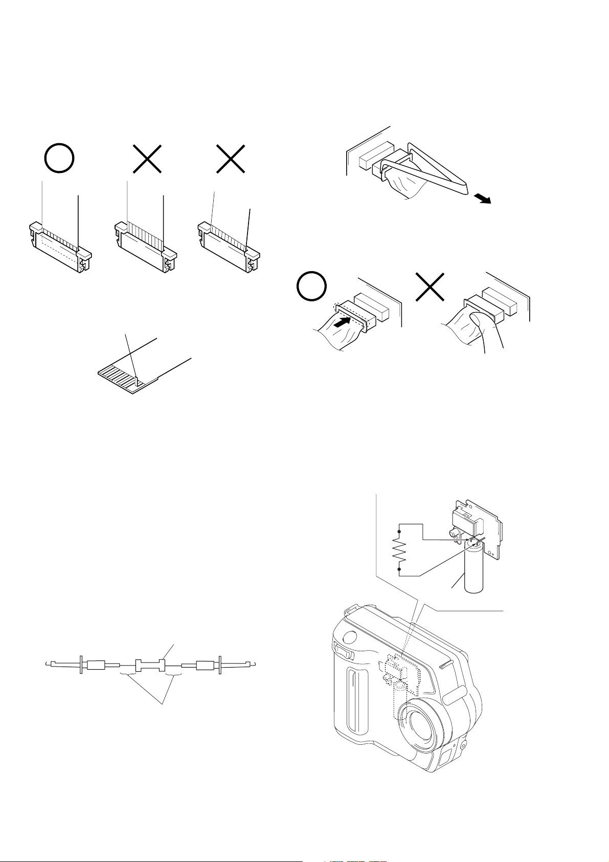
SERVICE NOTE
• NOTE FOR REPAIR
Make sure that the flat cable and flexible board are not cracked of
bent at the terminal.
Do not insert the cable insufficiently nor crookedly.
Cut and remove the part of gilt
which comes off at the point.
(Be careful or some pieces of
gilt may be left inside)
When remove a connector, don’t pull at wire of connector.
It is possible that a wire is snapped.
When installing a connector, don’t press down at wire of connector.
It is possible that a wire is snapped.
[Discharging of the FLASH unit’s charging capacitor]
The charging capacitor of the FLASH unit is charged up to the
maximum 300 V potential.
There is a danger of electric shock by this high voltage when the
battery is handled by hand. The electric shock is caused by the
charged voltage which is kept without discharging w hen the main
power of the MVC-FD200 is simply turned off. Therefore, the
remaining voltage must be discharged as described below.
Preparing the Short Jig
T o preparing the short jig. a small clip is attached to eac h end of a
resistor of 1 kΩ /1 W (1-215-869-11).
Wrap insulating tape fully around the leads of the resistor to prevent electrical shock.
Discharging the Capacitor
1 kΩ/1 W
Wrap insulating tape.
Short-circuit between the positive and the negative terminals of
charged capacitor with the short jig about 10 seconds.
R: 1 kΩ/1 W
(Part code:
1-215-869-11)
Capacitor
– 4 –
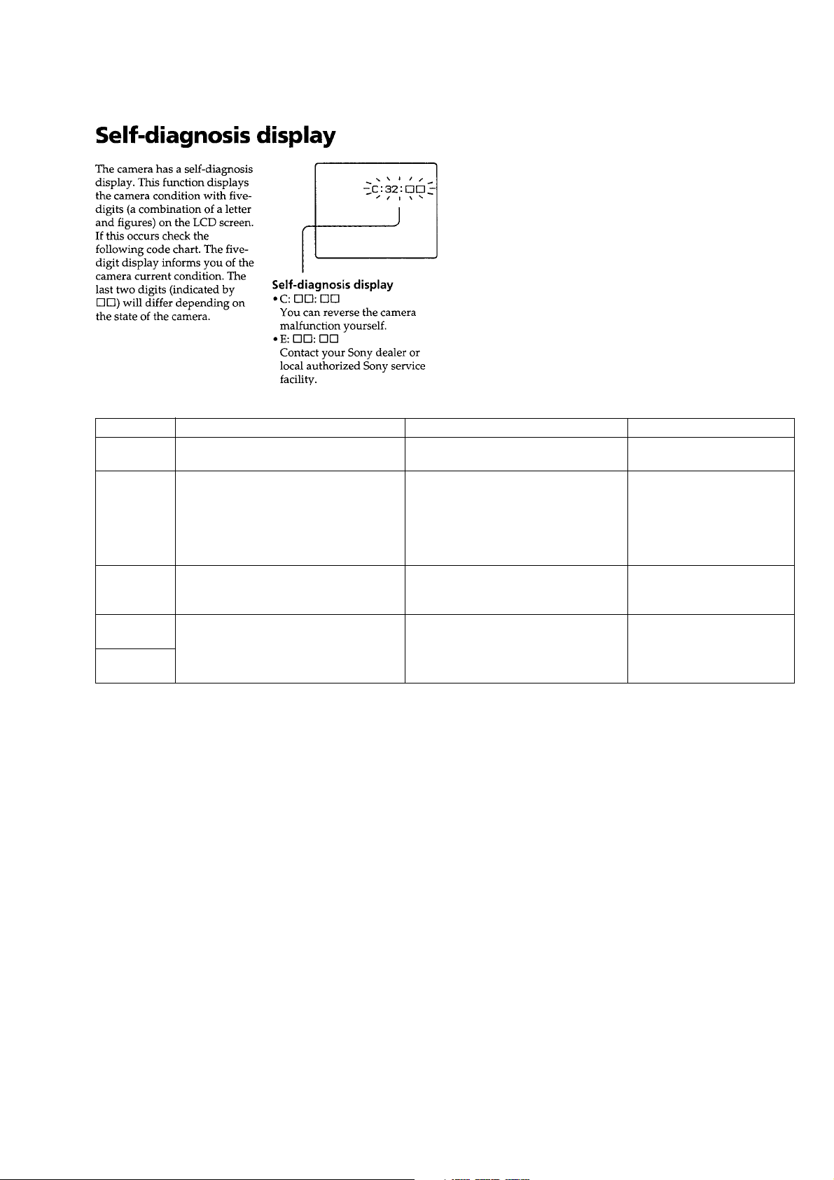
[Description on Self-diagnosis Display]
MVC-FD200
Note : The “Self-diagnosis” data is backed up by the coin lithiumbattery.
The data will be lost and initialized when the coin lithium battery
is removed.
Display Code
C:32:01
C:13:01
E:91:01
E:61:00
E61:10
Note : The error code is cleared if the battery is removed, except defective flash, unit.
*1: When the flash charging failed, Page: D, Address: 67, Data: 04 are written.
After repair, be sure to write Page: D, Address: 67, Data: 00.
[Power supplying Method]
Use the AC power adaptor (AC-L10A) when supplying the power to this set.
Change the disk and turn off the main
power then back on.
Replace the floppy disk or “Memory
Stick”.
Format the floppy disk or “Memory
Stick” with the MVC-FD200.
Checking of flash unit or replacement of
flash unit
Checking of lens drive circuit
Countermeasure
Cause
Defective floppy disk.
• The type of floppy disk that cannot be
used by this machine, is inserted.
(Such as 2DD)
• Data is damaged.
• Unformatted disk or “Memory Stick”
is inserted.
Abnormality when flash is being
charged.
When failed in the focus initialization.
Caution Display During Error
DRIVE ERROR
DISK ERROR
MEMORY STICK ERROR
Flash LED
*1
Flash display
Flashing at 3.2 Hz
—
– 5 –
MVC-FD200
1. MAIN PARTS
Note:
• Items marked “*” are not stocked since they are seldom required for routine service.
Some delay should be anticipated when ordering these items.
• The parts numbers of such as a cabinet are also appeared in this section.
Refer to the parts number mentioned below the name of parts to order.
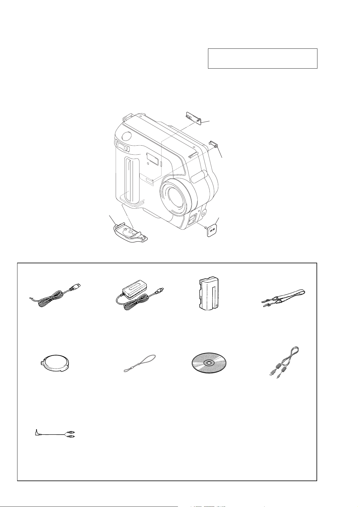
1. ORNAMENTAL PARTS
Note: When change it, need to dismantle the set.
The components identified by mark 0 or dotted
line with mark 0 are critical for safety.
Replace only with part number specified.
USB jack cover
3-066-802-21
(Note)
CPC lid
3-066-805-31
Battery lid
3-073-006-11
Checking supplied accessories.
Power cord (1)
0 1-769-608-11 (AEP)
0 1-783-374-11 (UK)
AC power adaptor
AC-L10A (1)
0 1-475-599-11
DC cover
3-072-999-11
(Note)
Battery pack
NP-F330 (1)
0 A-7094-141-A
Shoulder strap (1)
3-987-015-01
Lens cap (1)
X-3950-660-1
A/V connecting cable (1)
1-792-955-11
Lens cap strap (1)
3-067-797-01
– 6 –
CD-ROM
(SPVD-008 USB driver) (1)
3-072-414-01
Other accessories
3-073-074-11 MANUAL, INSTRUCTION (ENGLISH)
3-073-074-21 MANUAL, INSTRUCTION
(FRENCH, GERMAN) (AEP)
3-073-074-31 MANUAL, INSTRUCTION
(SPANISH, PORTUGUESE) (AEP)
3-073-074-41 MANUAL, INSTRUCTION
(ITALIAN, DUTCH) (AEP)
3-073-074-61 MANUAL, INSTRUCTION
(SWEDISH, RUSSIAN) (AEP)
USB cable (1)
1-823-931-11
2. DISASSEMBLY
2-1. CABINET (REAR) BLOCK
ASSEMBLY (Page 7)
2-2. USB CONNECTOR BLOCK
(Page 8)
2-5. FDD BLOCK ASSEMBLY
(Page 9)
2-3. FC-89 BOARD
(Page 8)
2-4. FDD
(Page 9)
2-6. LENS BLOCK ASSEMBLY
(Page 10)
MVC-FD100/FD200
2-7. PK-61 BOARD
(Page 10)
2-8. LCD MODULE
(Page 11)
• This set can be disassembled in the order shown below.
MVC-FD200
Note: Follow the disassembly procedure in the numerical order given.
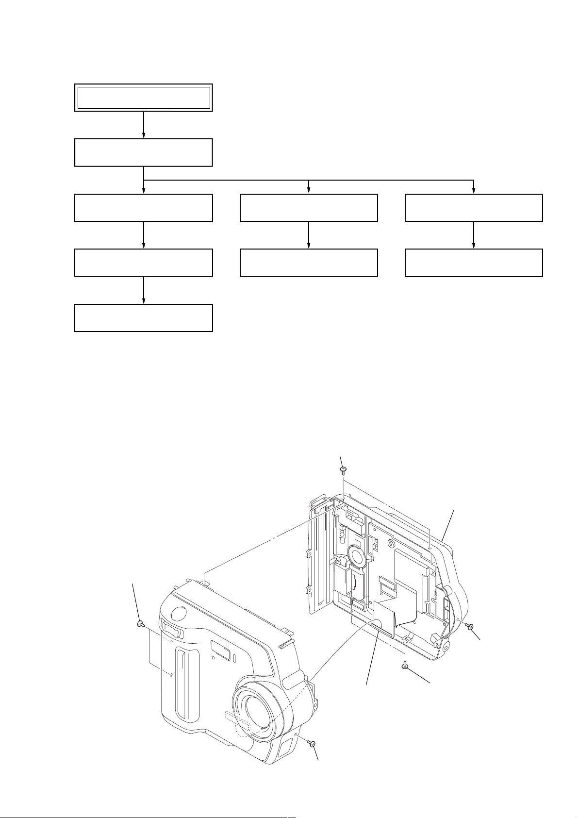
2-1. CABINET (REAR) BLOCK ASSEMBLY
5 Two screws (M2)
1 Two screws (M2)
7 Flexible board
(CN801)
6 Cabinet (rear) block assembly
2 Screw (M2)
3 Two screws (M2)
4 Screw (M2)
– 7 –
MVC-FD200
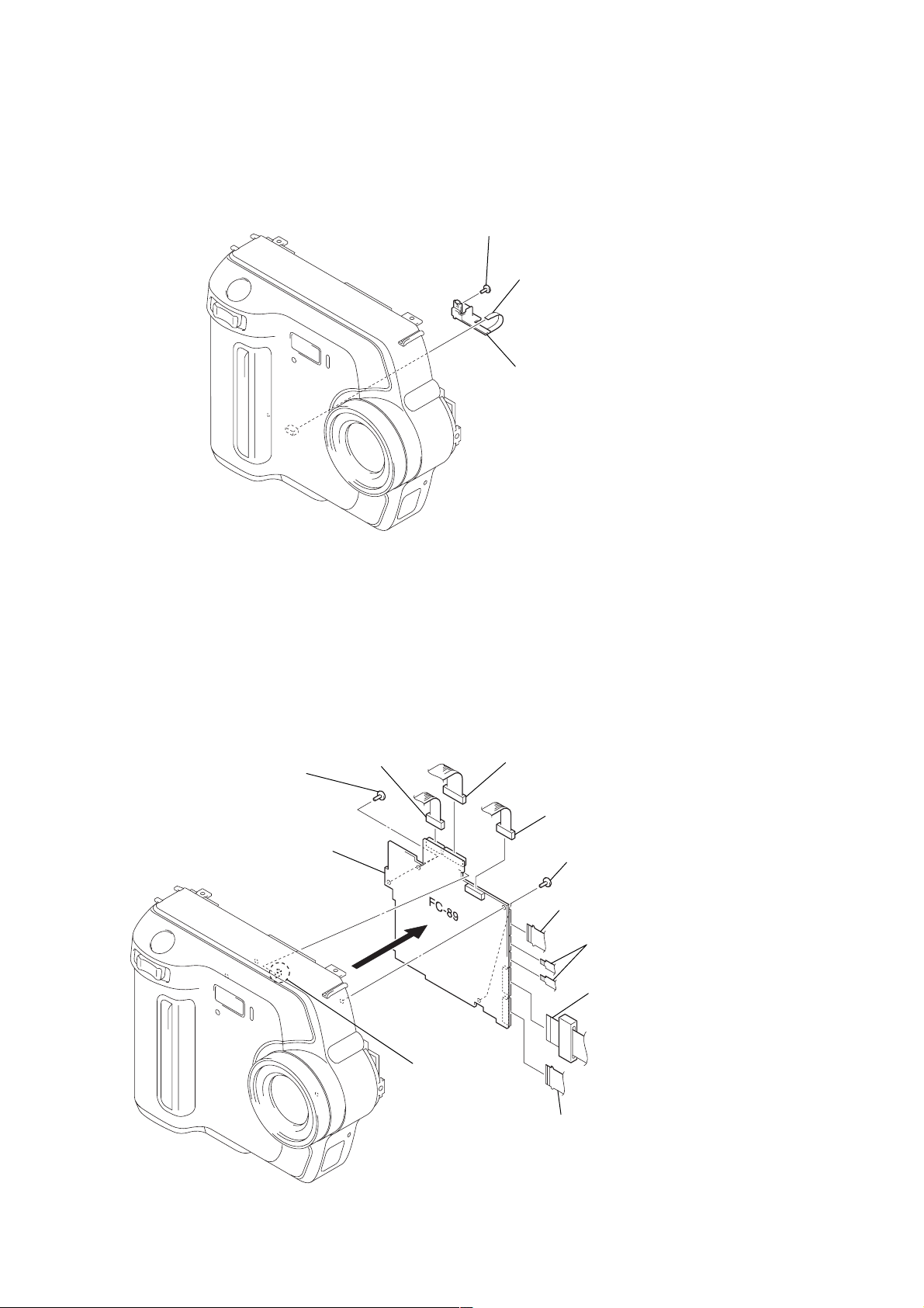
2-2. USB CONNECTOR BLOCK
1 Screw (M2)
2 Flexible board (CN682)
3 USB connector block
2-3. FC-89 BOARD
9 Two screws (M2)
qa FC-89 board
7 Connector
(CN002)
6 Connector
(CN001)
5 Connector
(CN301)
8 Two screws (M2)
1 Flexible board
(CN701)
2 Two flexible board
(CN702, 703)
3 FP-465 flexible board
(CN101)
0 Claw
4 FP-464 flexible board
(CN184)
– 8 –
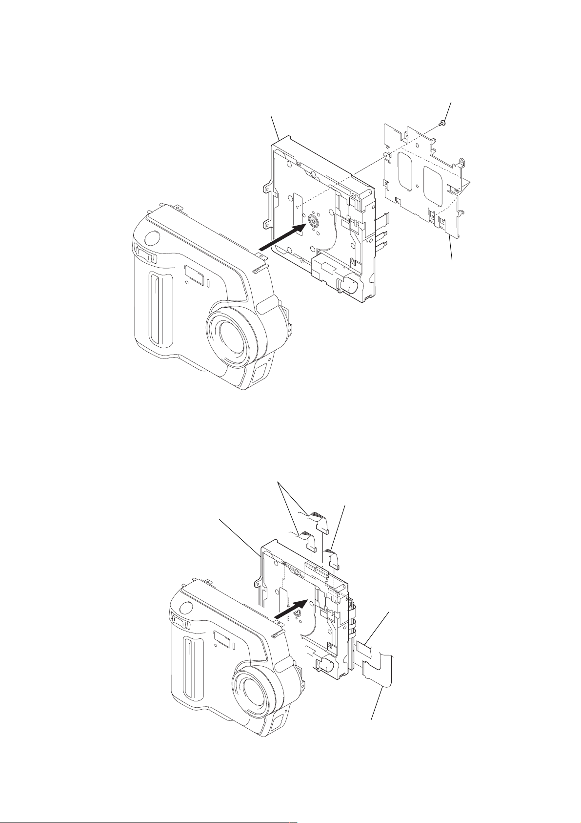
2-4. FDD
MVC-FD200
1 Three screws (M2)
3 FDD
2 FC bracket
2-5. FDD BLOCK ASSEMBLY
5 FDD block assembly
4 T wo connectors
(CN001, 002)
3 Connector
(CN301)
1 FP-465 flexible board
(CN101)
2 FP-464 flexible board (CN184)
– 9 –
MVC-FD200
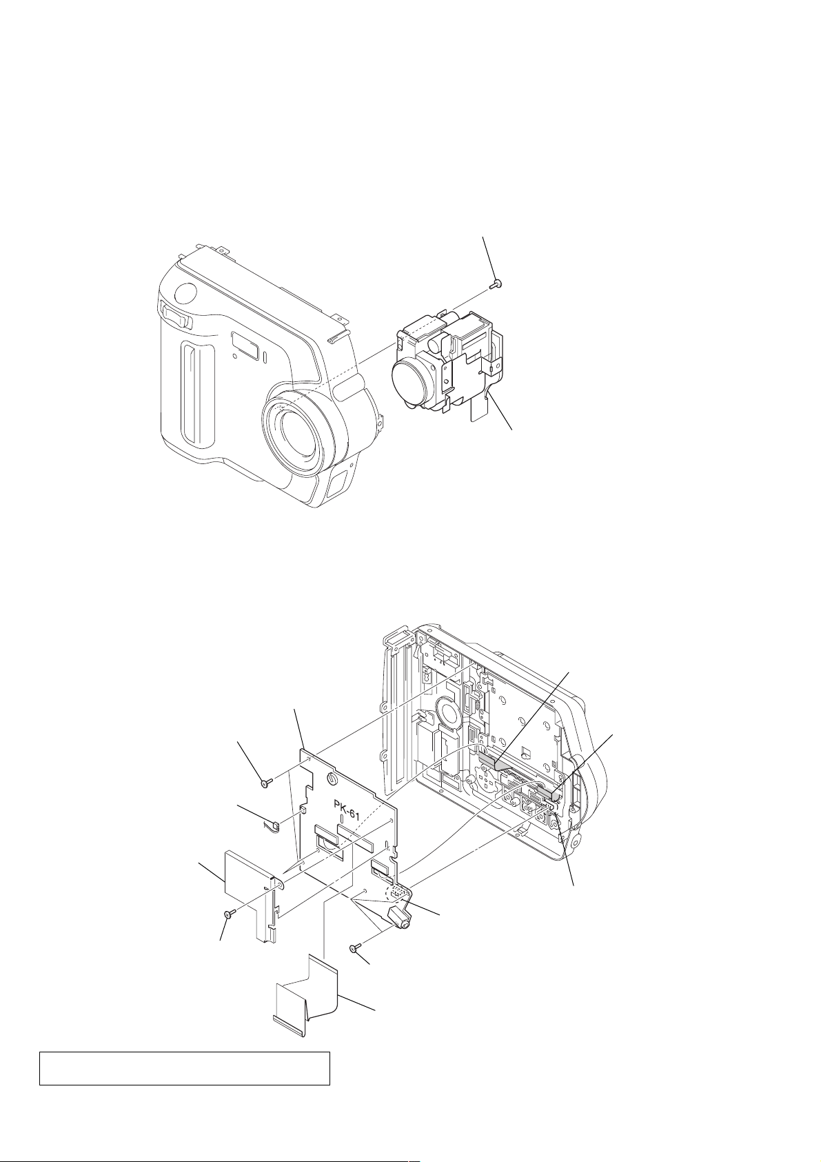
2-6. LENS BLOCK ASSEMBLY
1 Tapping screw
2-7. PK-61 BOARD
7 Three tapping screws
2 Lens block assembly
4 Flexible board
(CN902)
9 PK-61 board
5 Flexible board
(CN851)
3 Connector
(CN702)
2 PK shield case assembly
1 Tapping screw
Note: When installing PK-61 board, connect S709 with
LCD knob retainer.
LCD knob retainer
S709
8 Three tapping screws
6 FP466 flexible board
(CN701)
– 10 –
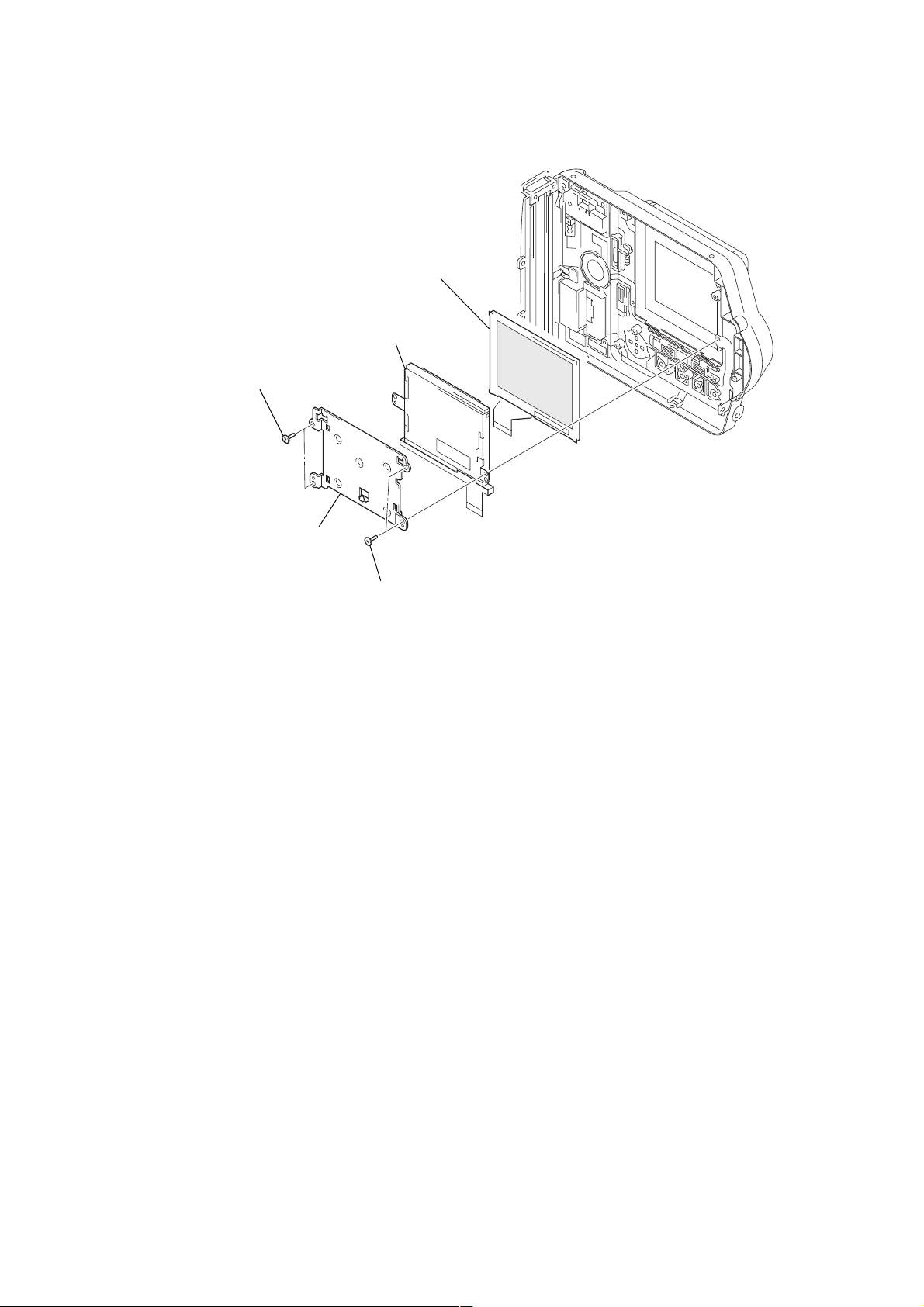
2-8. LCD MODULE
1 Two tapping screws
MVC-FD200
5 LCD module
4 Cold cathode
fluorescent tube
3 BL retainer
2 Two tapping screws
– 11 –
MVC-FD200
3-1. EXPLODED VIEWS
NOTE:
• -XX and -X mean standardized parts, so they may
have some difference from the original one.
• Items marked “*” are not stocked since they are
seldom required for routine service. Some delay
should be anticipated when ordering these items.
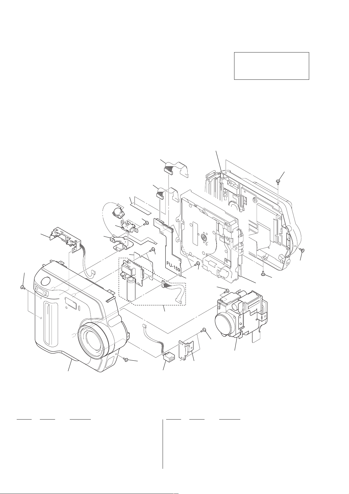
3-1-1. CABINET (FRONT) SECTION
3. REPAIR PARTS LIST
• The mechanical parts with no reference number in
the exploded views are not supplied.
Cabinet (rear) section
(See page 15.)
8
9
The components identified by mark
0 or dotted line with mark 0 are
critical for safety.
Replace only with part number specified.
10
BT901
10
Cabinet (front) assembly
(See page 13.)
11
2
7
6
4
2
10
2
5
2
10
FDD block section
(See page 14.)
3
2
Lens block section
10
J001
(See page 17.)
1
Ref. No. Part No. Description Ref. No. Part No. Description
1 3-073-018-01 RETAINER, DC
2 3-948-339-61 TAPPING
0 3 not supplied FLASH UNIT
* 4 3-058-801-01 SHEET, ST INSULATING
5 not supplied FU-159 BOARD, COMPLETE
6 1-418-894-11 SWITCH BLOCK, CONTROL
7 3-073-019-01 HOLDER, SW
8 1-961-478-11 HARNESS (FU-055)
9 1-961-479-11 HARNESS (FU-056)
10 3-968-729-31 SCREW (M2), LOCK ACE, P2
* 11 3-061-228-01 RETAINER, HARNESS
BT901 1-694-297-21 TERMINAL BOARD, BATTERY
J001 1-794-045-21 CONNECTOR, DC-IN
– 12 –
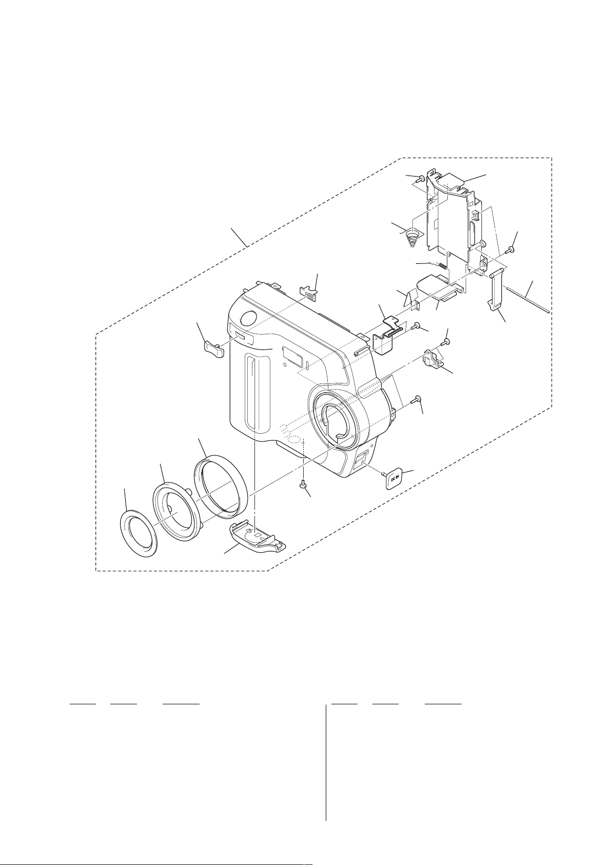
3-1-2. CABINET (FRONT) ASSEMBLY
MVC-FD200
52
53
69
54
51
70
58
63
59
64
61
57
68
60
64
64
62
64
65
66
67
56
55
Ref. No. Part No. Description Ref. No. Part No. Description
51 X-3952-212-1 CABINET (FRONT) ASSY
52 X-3952-207-1 LABEL ASSY, LENS
53 3-073-008-01 SCREW, FILTER
54 3-073-005-01 RING, ORNAMENTAL
55 3-073-006-11 LID, BATTERY
56 3-719-381-01 SCREW (M2X4)
57 3-072-999-11 COVER, DC
58 3-073-013-01 SHEET METAL (L), STRAP
59 3-066-775-01 SPRING, BT PLATE
60 3-066-772-01 PLATE, HINGE
61 3-066-778-01 SPRING, BT TORSION
62 3-066-773-01 HOLDER, BATTERY
63 3-969-380-01 SPRING, BATTERY
64 3-948-339-01 SCREW, TAPPING
65 3-066-774-01 SHAFT, HINGE
66 3-052-574-01 CLAW, BT LOCK
67 3-058-755-01 SCREW, TRIPOD
68 3-713-791-41 SCREW (M1.7X5), TAPPING, P2
69 3-073-010-11 KNOB, ZOOM
70 3-073-011-01 SLIDER, ZOOM
– 13 –
 Loading...