

Page 1
MVC-CD500
SERVICE MANUAL
Ver 1.0 2003. 04
Revision History
Revision History
Link
Link
SELF DIAGNOSIS FUNCTION
SELF DIAGNOSIS FUNCTION
LEVEL 1
US Model
Canadian Model
AEP Model
UK Model
E Model
Australian Model
Japanese Model
ORNAMENTAL PARTSSPECIFICATIONS
ORNAMENTAL PARTSSPECIFICATIONS
• INSTRUCTION MANUAL is shown at the end of this document.
DIGITAL STILL CAMERA
Page 2

MVC-CD500
COVER
COVER
x Camera
[System]
Image device
Total pixels number of camera
Effective pixels number of camera
Lens 3 zoom lens
Exposure control
White balance
File format (DCF compliant)
Recording media
Flash Recommended distance (ISO set to
[Drive]
Readout Non-contact optical readout (using
Laser Wavelength: 779 to 789 nm
9.04 mm (1/1.8 type) color CCD
Primary color filter
Approx. 5 255 000 pixels
Approx. 5 090 000 pixels
f = 7.0 – 21.0 mm (9/32 – 27/32
inches) (34 – 102 mm (1 3/8 – 4 1/8
inches) when converted to a 35 mm
still camera)
F2.0 – 2.5
Automatic exposure, Shutter speed
priority, Aperture priority, Manual
exposure, Scene selection (6 modes)
Automatic, Daylight, Cloudy,
Fluorescent, Incandescent, Flash,
One-push
Still images: Exif Ver. 2.2 JPEG
compliant, GIF (for Clip Motion),
TIFF, DPOF compatible
Audio with still image: MPEG1
compliant (Monaural)
Movies: MPEG1 compliant
(Monaural)
8 cm CD-R/CD-RW
Auto): 0.5 m to 5.0 m (19 3/4 inches
to 196 7/8 inches)
semiconductor laser)
Maximum output: 23 mW
SPECIFICATIONS
[Input and Output connectors]
A/V OUT (MONO) (Monaural)
ACC jack Mini-minijack (ø 2.5 mm)
USB jack mini-B
[LCD screen]
LCD panel
Total number of dots
[General]
Used battery pack
Power requirements
Power co nsumption (d uring shooti ng with
LCD backlight on)
Operating temperature
Storage temperature
Dimensions
Mass Approx. 606 g (1 lb 5 oz) (including
Built-in microphone
Built-in speaker
Exif Print Compatible
PRINT Image Matching II Compatible
Minijack
Video: 1 Vp-p, 75 Ω, unbalanced,
sync negative
Audio: 327 mV (at a 47 kΩ load)
Output impedance 2.2 kΩ
6.2 cm (2.5 type) TFT drive
123 200 (560 × 220) dots
NP-FM50
7.2 V
3.0 W
0°C to 40°C (32°F to 104°F)
–20°C to +60°C (4°F to +140°F)
138.5 × 95.7 × 103.1 mm
(5 1/23 × 7/84 × 1/8 inches)
(W/H/D, excluding maximum
protrusions)
battery pack NP-FM50, disc, and lens
cap)
Electret condenser microphone
Dynamic speaker
x AC-L15A/L15B AC Adaptor
Power re quirements
Current consumption
Power consumption
Output voltage
Operating temperature
Storage temperature
Dimensions (approx.)
Mass (approx.)
100 – 240 V AC, 50/60 Hz
0.35 – 0.18 A
18 W
8.4 V DC, 1.5 A
0°C to 40°C (32°F to 104°F)
–20°C to +60°C (–4°F to +140°F)
56 × 31 × 100 mm
(2 1/4 × 1 1/4 × 4 inches) (w/h/d)
excluding projecting parts
190 g (6.7 oz) excluding power cord
(mains lead)
x NP-FM50 battery pack
Used battery
Maximum voltage
Nominal voltage
Capacity 8.5 Wh (1 180 mAh)
Lithium-ion battery
DC 8.4 V
DC 7.2 V
x Accessories
AC Adaptor (1)
Power cord (mains lead) (1)
USB cable (1)
NP-FM50 battery pack (1)
A/V connecting cable (1)
8 cm CD adaptor (1)
Mavica disc (2) (CD-R (1), CD-RW (1))
Shoulder strap (1)
Lens cap (1)
Lens cap strap (1)
CD-ROM (SPVD-010) (1)
Operating instructions (1)
Design and specifications are subject to change
without notice.
— 2 —
Page 3

MVC-CD500
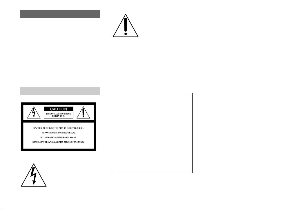
CAUTION
Use of controls or adjustments or performance
procedures other than those specified herein may
result in hazardous radiation exposure.
WARNING!!
WHEN SERVICING, DO NOT APPROA CH THE LASER
EXIT WITH THE EYE TOO CLOSELY. IN CASE IT IS
NECESSARY TO CONFIRM LASER BEAM EMISSION,
BE SURE TO OBSER VE FROM A DISTANCE OF MORE
THAN 30 cm FROM THE SURFACE OF THE
OBJECTIVE LENS ON THE OPTICAL PICK-UP BLOCK.
CAUTION :
Danger of explosion if battery is incorrectly replaced.
Replace only with the same or equivalent type.
SAFETY-RELATED COMPONENT WARNING!!
COMPONENTS IDENTIFIED BY MARK 0 OR DOTTED LINE WITH
MARK 0 ON THE SCHEMATIC DIAGRAMS AND IN THE PARTS
LIST ARE CRITICAL TO SAFE OPERATION. REPLACE THESE
COMPONENTS WITH SONY PARTS WHOSE PART NUMBERS
APPEAR AS SHOWN IN THIS MANUAL OR IN SUPPLEMENTS
PUBLISHED BY SONY .
CAUTION:
The use of optical instrument with this product will increase eye
hazard.
ATTENTION AU COMPOSANT AYANT RAPPORT
À LA SÉCURITÉ!
LES COMPOSANTS IDENTIFÉS P AR UNE MARQUE 0 SUR LES
DIAGRAMMES SCHÉMA TIQUES ET LA LISTE DES PIÈCES SONT
CRITIQUES POUR LA SÉCURITÉ DE FONCTIONNEMENT. NE
REMPLACER CES COMPOSANTS QUE PAR DES PIÈSES SONY
DONT LES NUMÉROS SONT DONNÉS DANS CE MANUEL OU
DANS LES SUPPÉMENTS PUBLIÉS PAR SONY.
After correcting the original service problem, perform the following
safety checks before releasing the set to the customer.
1. Check the area of your repair for unsoldered or poorly-soldered
connections. Check the entire board surface for solder splashes
and bridges.
2. Check the interboard wiring to ensure that no wires are
"pinched" or contact high-wattage resistors.
3. Look for unauthorized replacement parts, particularly
transistors, that were installed during a previous repair. Point
them out to the customer and recommend their replacement.
4. Look for parts which, through functioning, show obvious signs
of deterioration. Point them out to the customer and
recommend their replacement.
5. Check the B+ voltage to see it is at the values specified.
6. Flexible Circuit Board Repairing
• Keep the temperature of the soldering iron around 270˚C
during repairing.
• Do not touch the soldering iron on the same conductor of the
circuit board (within 3 times).
• Be careful not to apply force on the conductor when soldering
or unsoldering.
SAFETY CHECK-OUT
Unleaded solder
Boards requiring use of unleaded solder are printed with the leadfree mark (LF) indicating the solder contains no lead.
(Caution: Some printed circuit boards may not come printed with
the lead free mark due to their particular size.)
: LEAD FREE MARK
Unleaded solder has the following characteristics.
• Unleaded solder melts at a temperature about 40°C higher than
ordinary solder.
Ordinary soldering irons can be used but the iron tip has to be
applied to the solder joint for a slightly longer time.
Soldering irons using a temperature regulator should be set to
about 350°C.
Caution: The printed pattern (copper foil) may peel away if the
heated tip is applied for too long, so be careful!
• Strong viscosity
Unleaded solder is more viscous (sticky, less prone to flow) than
ordinary solder so use caution not to let solder bridges occur such
as on IC pins, etc.
• Usable with ordinary solder
It is best to use only unleaded solder but unleaded solder may
also be added to ordinary solder.
— 3 —
Page 4
MVC-CD500
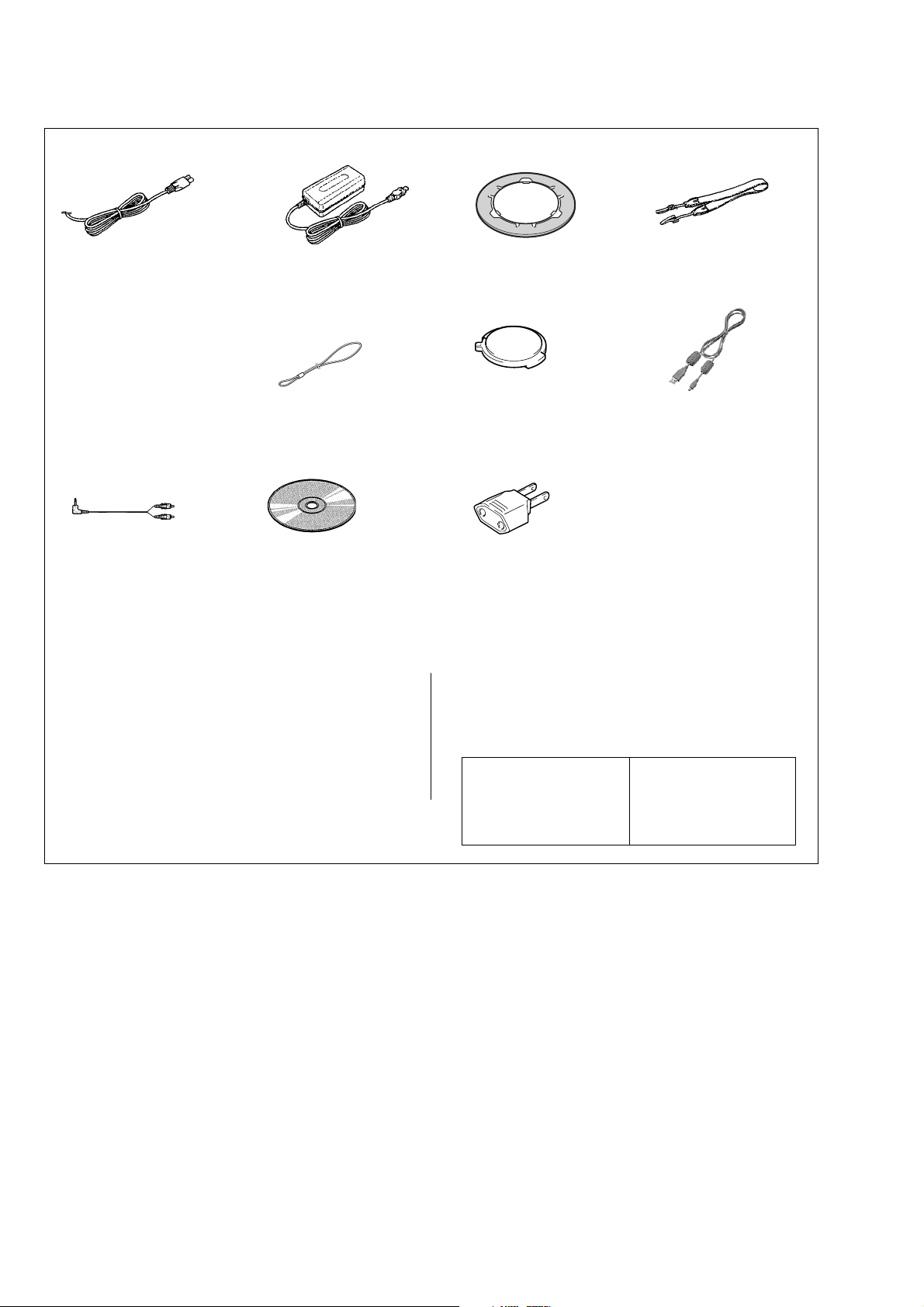
Checking supplied accessories.
Make sure that the following accessories are supplied with your camcorder.
Power cord (1)(AUS model)
0
1-696-819-11
Power cord (1)(AEP, E model)
0
1-769-608-11
AC power adaptor (1)
(AC-L15A/L15B)
0
1-477-533-31
Power cord (1)(UK model)
0
1-783-374-11
Power cord (1)
(US,CND model)
0
1-790-107-22
Power cord (1)( J model)
0
1-790-732-12
Lens cap string (1)
3-067-797-01
A/V connecting cable
(1.5m) (1)
1-824-111-11
CD-ROM (SPVD-010) (1)
(AEP, UK, E, AUS, KR model)
3-078-942-03
CD-ROM (SPVD-010(I)) (1)
(US, CND, J model)
3-078-943-03
Other accessories
3-081-837-01 MANUAL, INSTRUCTION (JAPANESE)(J)
3-081-837-11 MANUAL, INSTRUCTION (ENGLISH)
3-081-837-21 MANUAL, INSTRUCTION (FRENCH/GERMAN)(CND,AEP)
3-081-837-31 MANUAL, INSTRUCTION (SPANISH/PORTUGUESE)
3-081-837-41 MANUAL, INSTRUCTION (ITALIAN/DUTCH)(AEP)
(US,CND,AEP,UK,E,AUS)
(AEP,E)
8 cm CD adaptor (1)
(D adaptor)
Shoulder strap (1)
3-071-638-01
3-063-085-01
Lens cap (1)
X-3951-672-1
2P conversion adaptor (1)
(E model)
1-569-008-12
3-081-837-51 MANUAL, INSTRUCTION (CHINESE)(E)
3-081-837-61 MANUAL, INSTRUCTION (SWEDISH)(AEP)
3-081-837-71 MANUAL, INSTRUCTION (ARABIC)(E)
3-081-838-01 OPERATING INSTRUCTION (J)
Note :
The components identified by
mark 0 or dotted line with mark
0 are critical for safety.
Replace only with part number
specified.
USB cable (1)
1-827-038-11
• Abbreviation
CND : Canadian model
AUS : Australian model
J : Japanese model
Note :
Les composants identifiés par
une marque 0 sont critiques
pour la sécurité.
Ne les remplacer que par une
pièce portant le numéro spécifié.
— 4 —
Page 5

MVC-CD500
COVER
COVER
[Description on Self-diagnosis Display]
Self-diagnosis display
• C: ss: ss
The contents which can be handled
by customer, are displayed.
• E: ss: ss
The contents which can be handled
by engineer, are displayed.
Display Code
C:32:01
C:13:01
E:91:01
*1
E:61:00
*1
E:61:10
Change the disk and turn off the main
power then back on.
Replace the CD-R/RW disk.
Checking of flash unit or replacement of
flash unit
Checking of lens drive circuit
Countermeasure
SELF-DIAGNOSIS FUNCTION
Cause
Defective base unit.
• The type of CD-R/RW disk that cannot
be used by this machine, is inserted.
• Data is damaged.
Abnormality when flash is being
charged.
When failed in the focus initialization.
Caution Display During Error
DRIVE ERROR
DISK ERROR
Flash LED
Flash display
Flashing at 3.2 Hz
—
Note: The error code is cleared if the battery is removed.
*1 : The error display is given in two ways.
— 5 —
Page 6
MVC-CD500
COVER
COVER
Note:
• Follow the disassembly procedure in the numerical order given.
• Items marked “*” are not stocked since they are seldom required for routine service.
Some delay should be anticipated when ordering these items.
• The parts numbers of such as a cabinet are also appeared in this section.
Refer to the parts number mentioned below the name of parts to order.
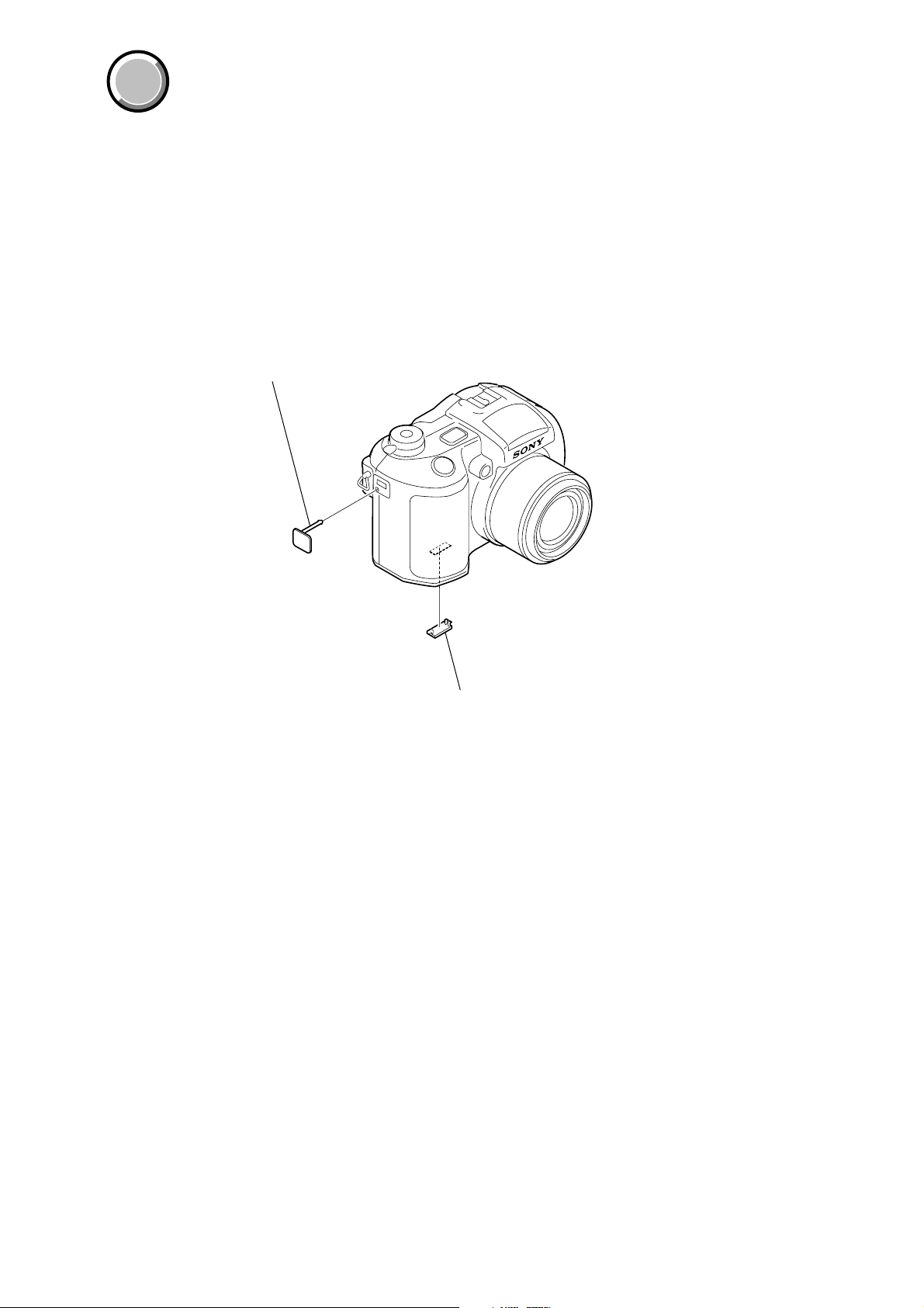
MAIN PARTS
1. ORNAMENTAL PARTS
DC cover
3-073-570-11
(When change it, need to dismantle the set.)
CPC lid
3-073-661-11
— 6 —
Page 7

MVC-CD500
9-876-216-41
Sony EMCS Co.
— 8 —
2003D1600-1
©2003.4
Published by DI Customer Center
Page 8

3-081-837-12(1)
_
_
_
_
_
_
_
_
_
_
_
_
_
Getting started _______________________
Digital Still Camera
Operating Instructions
Before operating the un it, pl ea se read this manual thorough ly, and
retain it for future reference .
Owner’s Record
The model and serial nu mb ers are located on the botto m. Re cord the
serial number in the space provided below. Refer to these numbers
whenever you call upon your Sony dealer regarding this product.
Model No. MVC-CD500
Serial No.
MVC-CD500
© 2003 Sony Corporation
Shooting still images_________________
Viewing still images__________________
Deleting still images _________________
Before advanced operat ions____________
Advanced still image shooting __________
Advanced still image viewing ___________
Still image editing _____________________
Enjoying movies ______________________
Enjoying images on your computer______
Troubleshooting ______________________
Additional information__________________
Index _____________________________
Page 9
WARNING
To prevent fire or shock hazard, do
not expose the unit to rain or
moisture.
CAUTION
The use of optical instruments with this
product will in crease eye hazard.
Use of controls or adjustments or
performance of procedures other than those
specified herein may result in haz ard ous
radiation exposure.
For the Customers in the U.S.A.
This symbol is intended to alert
the user to the presence of
uninsulated “dangerous
voltage” within the product’s
enclosure that may be of
sufficient magnitude to
constitute a risk of electric
2
shock to persons.
This symbol is intended to alert
the user to the presence of
important operating and
maintenance (servicing)
instructions in the literature
accompanying the appliance.
If you have any questions about this product,
you may call:
Sony Customer Information Center
1-800-222-SONY (7669)
The number below is for the FCC related matters
only.
Regulatory Information
Declaration of Conformity
Trade Name: SONY
Model No.: MVC-CD500
Responsible Party: Sony Electronics Inc.
Address: 680 Kinderkamack Road,
Oradell, NJ 07649 USA
Telephone No.: 201-930-6972
This device complies with Part 15 of the
FCC Rules. Operation is subject to the
following two conditions: (1) This device
may not cause harmful interfe renc e , a nd
(2) this device must acc ept any interf erence
received, including interference that may
cause undesired operation.
CAUTION
Y ou are cautio ned that any changes or
modifications not expressly approved in this
manual could void your authority to operate this
equipment.
Note:
This equipment has been tested and found to
comply with the limits for a Class B digital
device, pursuant to Part 15 of the FCC Rules.
These limits are designed to provide reasonable
protection against harmful interference in a
residential installation. This equipment generates,
uses, and can radiate radio frequency energy and,
if not installed and used in accordance with the
instructions, may cause harmful interfe renc e to
radio communications. However, there is no
guarantee that interference will not occur in a
particular installation. If this equipment does
cause harmful interference to radio or television
reception, which can be determined by turning
the equipment off and on, the user is encouraged
to try to correct the interference by one or more of
the following measures:
— Reorient or relocate the receiving antenna.
— Increase the separation between the
equipment and receiver.
— Connect the equipment into an outlet on a
circuit different from that to which the
receiver is connected.
— Consult the dealer or an experienced radio/
TV technician for help.
The shielded interface cable recommended in this
manual must be used with the equipment in order
to comply with the limits for a digital device
pursuant to Subpart B of Part 15 of FCC Rules.
Page 10

For the Customers in the U .S.A.
and Canada
RECYCLING LITHIUM-ION
BATTERIES
Lithium-Ion b a tteries are
recyclable.
You can help preserve our
environment by returning your
used rechargeable batteries to
the collection and recycling location nearest
you.
For more information regarding recycling of
rechargeable batteries, call toll free
1-800-822-8837, or visit
http://www.rbrc.org/
Caution:Do not handle damaged or leaki ng
Lithium-Ion batteries.
CAUTION
TO PREVENT ELECTRIC SHOCK, DO NOT
USE THIS POLARIZED AC PLUG WITH AN
EXTENSION CORD, RECEPTACLE OR
OTHER OUTLET UNLESS THE BLADES
CAN BE FULLY INSERTED TO PREVENT
BLADE EXPOSURE.
Notice on the supplied AC
Adaptor for the customers in
the United Kingdom
A moulded plug complying with BS 1363 is fitted
to this equipment for your safety and
convenience.
Should the fuse in the plug supplied need to be
replaced, a 5 AMP fuse approved by ASTA or
BSI to BS 1362, (i.e., marked with or
mark) must be used.
If the plug supplied with this equipm e nt ha s a
detachable fuse cover, be sure to attach the
fuse cover after you change the fuse. Never
use the plug without the fuse cover. If you
should lose the fuse cover, please contact your
nearest Sony service station.
Attention for the Customers in
Europe
This product has been tested and found compliant
with the limits sets out in the EMC Directive for
using connection cables shorter than 3 meters
(9.8 feet).
This statement is indicated under the lens.
Attention
The electromagnetic field at the specific
frequencies may influence the picture and sound
of this camera.
Notice
If static electricity or electromagnetism causes
data transfer to discontinue midway (fail), res tart
the application or disconnect and connect the
USB cable again.
Notice
Certain countries may regulate disposal of the
battery used to power this product. Please consult
with your local authority.
3
Page 11

Before using your camera
This digital still camera uses 8 cm CD-Rs/ CD RWs as recording media. “CD-R” or “CD-R W”
mentioned above is indicated as “disc” in this
manual. When a distinction between CD-Rs and
CD-RWs is necessary, “disc” is indicated as
“CD-R” or “CD-RW.”
Refer to page 18 for discs that can be used with
this camera, and page 120 for precautions on
handling discs.
• We recommend that you use
this camera with Mavica
discs*.
• While the image is being
read from or written to the
disc, the ACCESS lamp
flashes (red). When this
lamp is lit, do not shake or
strike the camera.
∗ The Mavica dis c is an 8 cm CD- R /C D- RW
with the Mavica logo.
Trial recording
Before you record one-time events, you may want
to make a trial recording to make sure that the
camera is working correctly.
4
No compensation for contents of the
recording
Contents of the recording cannot be compensated
for if recording or playback is not possible due to
a malfunction of your camera or recording media,
etc.
Back up recommendation
To avoid the potential risk of data loss, always
copy (back up) data to a disk.
Notes on image data compatibility
• This camera conforms with the Design rule for
Camera File system universal standard
established by the JEITA (Japan Electronics
and Information Technology Industries
Association).
• Playback of images recorded with your camera
on other equipment and playback of images
recorded or edited with other equipment on
your camera are not guaranteed.
Precaution on copyright
Television programs, films, video tapes, and other
materials may be copyrighted. Unauthorized
recording of such materials may be contrary to
the provision of the copyright laws.
Do not shake or strike the camera
In addition to malfunctions and inability to record
images, this may render the discs unusable or
image data breakdown, damage or loss may
occur.
LCD screen, LCD finder (only models
with an LCD finder) and lens
• The LCD screen and the LCD finder are
manufactured using extremely high-precision
technology so over 99.99% of the pixels are
operational for effective use. However, there
may be some tiny black points and/or bright
points (white, red, blue or green in color) that
constantly appear on the LCD screen and the
LCD finder. These points are normal in the
manufacturing process and do not affect the
recording in any way.
• Be careful when placing the camera near a
window or outdoors. Exposing the LCD screen,
the finder or the lens to direct sunlight for long
periods may cause malfunctions.
• Do not press the LCD screen hardly. The screen
may be uneven and that may cause a
malfunction.
• Images may be trailed on the LCD screen in a
cold location. This is not a malfunction.
Clean the flash surface before use
The heat of flash emission may cause dirt on the
flash surface to become discolored or to stick to
the flash surface, resulting in insufficient light
emission.
Do not get the camera wet
When taking pictures outdoors in the rain or
under similar conditions, be careful not to get the
camera wet. If moisture condensation occurs, see
page 120 and follow the instructions on how to
remove it before using the camera.
Page 12

Do not expose the camera to sand or
dust
Using the camera in sandy or dusty locations may
cause malfunction.
Do not aim the camera at the sun or
other bright light
This may cause irrecoverable damage to your
eyes. Or it may cause the malfunction of your
camera.
Notes on the camera locations
• Do not use the camera near a location that
generates strong radio wave or emits radiation.
The camera may not be able to record or play
back properly.
• Do not use the camera near a TV, radio, tuner.
Noise may be caused on the camera.
The pictures used in this manual
The photographs used as examples of pictures in
this manual are reproduced images, and are not
actual images shot using this camera.
Handling of the movab le le n s
This camera uses a movable lens. Be careful not
to strike or apply excessive force to the lens
portion.
Trademarks
• “InfoLITHIUM” is a trademark of Sony
Corporation.
• Microsoft and Windows are registered
trademarks of the U.S. Microsoft Corporation
in the United States and other countries.
• Macintosh and Mac OS are trademarks or
registered trademarks of Apple Computer, Inc.
• Pentium is a trademark or a registered
trademark of Intel Corporation.
• In addition, system and product names used in
this manual are, in general, trademarks or
registered trademarks of their respective
developers or manufacturers. However, the
or ® marks are not used in all cases in this
manual.
™
About the Carl Zeiss lens
This camera is equipped with a Carl Zeiss
lens which is capable of reproducing fine
images. The lens for this camera uses the
MTF* measurement system for cameras
developed jointly by Carl Zeiss, in Germany,
and Sony Corporation, and offers the same
quality as other Carl Zeiss lenses.
∗ MTF is an abbr eviation of Modulation
Transfer Function, a nu me r ic value
indicating the amount of light f ro m a
specific part of the subject gathered at
the corresponding positio n in the ima ge .
5
Page 13

Table of contents
Before using your camera.........................4
Introduction...............................................8
Identifying the parts ................................. 9
Getting started
Charging the battery pack.......................11
Using an external power source..............14
Using your camera abroad......................14
Turning on/off your camera....................15
How to use the control button.................15
Setting the date and time.........................16
Shooting still images
Inserting and removing a disc.................18
Initializing a disc.....................................19
What is initialization?.........................19
Setting the still image size......................20
Image size and quality ............................21
Basic still image shooting
— Auto adjustment mode.......... .....22
Checking the last image you sh ot
— Quick Review............................24
Using the zoom feature....................... 25
Shooting close-ups — Macro.............26
Using the self-timer............................ 27
Selecting a flash mode........................27
Indicators on the screen during
shooting..........................................30
Inserting the date and time on a still
image..............................................31
6
Viewing still images
Viewing images on the LCD screen of your
camera............................................ 32
Viewing images on a TV screen.............34
Deleting still images
Deleting images.............................. ........ 36
Formatting a CD-RW............................. 39
Before advanced operations
How to setup and operat e your camera .. 41
Changing the menu settings............... 41
Changing the items in the SET UP
screen .............................................41
How to use the jog dial....................... 42
Deciding the still image quality.............. 43
Creating or selecting a folder................. 43
Creating a new folder.........................44
Changing the recording folder ........... 44
Advanced still image
shooting
Shooting with Program Shift
— Program Shift............................45
Shooting with the manual adjustments... 45
Shutter speed priority mode............... 46
Aperture priority mode............... ........ 47
Manual exposure mode......................47
Choosing an auto focus method.............47
Choosing a focus range finder frame
— AF range finder..........................48
Choosing a focus operation
— AF Mode....................................49
Setting the distance to the subject
— Focus preset ...............................50
Adjusting the exposure
— EV adjustment...........................51
Displaying a histogram.......................52
Selecting the metering mode...................53
Shooting w ith the exposure fixed
— AE LOCK ..................................54
Shooting three images with the exposure
shifted — Exposure Bracket...........55
Adjusting color tones
— White Balance ...........................57
Adjusting the flash level
— Flash Level................................58
Shooting multiple fra mes
— Clip Motion ...............................59
Shooting in Multi Burst mode
— Multi Burst.................................60
Shooting three images continuously
— Burst 3 .......................................61
Shooting still images in TIFF mode
— TIFF ...........................................62
Shooting still images for e-mail
— E-Mail........................................62
Shooting still images with audio files
— Voice..........................................63
Page 14

Shooting according to scene conditions
— Scene Selection...................... ....64
Adding special effects
— Picture Effect.............................65
Confirming whether to record images
— Confirm before write.................66
Using an external flash............................67
Using the Sony HVL-F32X Flash ......67
Using the Sony HVL-F1000 Flash .....68
Using a commercially available external
flash ................................................68
Still image editing
Protecting images — Protect..................75
Changing image size — Resize..............77
Choosing images to print
— Print (DPOF) mark....................77
Enjoying movies
Shooting movies.....................................80
Viewing movies on the LCD screen....... 81
Deleting movies — Delete......................82
Connecting the came ra t o your
computer.........................................93
Copying images........................... ........94
When the PTP Manager does not
start up............................. ................95
Copying images using the Window s XP
AutoPlay Wizard.......... ................. ..96
Viewing images on your computer .....96
Creating a Video CD...........................96
For Mac OS X users
(v10.0/v10.1/v10.2).........................97
Advanced still image viewing
Selecting the folder an d playing back
images — Folder ............................69
Enlarging a portion of a still image.........70
Enlarging an image
— Playback zoom.................... .......70
Recording an enlarged image
— Trimming...................................71
Playing back successive images
— Slide Show.................. ...............71
Rotating still images
— Rotate.........................................72
Playing back images sh ot in Multi Burst
mode ...............................................73
Playing back continuously..................73
Playing back frame by fr am e
— Jog playback..............................73
Enjoying images on your
computer
Viewing images on your computer
— Introduction...............................84
Viewing images using CD-RO M drive .. 85
Finalizing a disc..................................85
What is finalization?...........................85
Canceling finalizati on (U nfinalize)
(CD-RW only)................................86
Using the supplied 8cm CD a dapter... 87
Viewing images throug h a CD -ROM
drive................................................88
Image file storage destinati ons and
image file names ............................89
Copying images into your computer
through a USB connection.............91
Installing the PTP Manager................91
Installing “ImageMixer”..................... 92
Troubleshooting
Troubleshooting ......................................98
Warnings and messages........................107
Self-diagnosis display ...........................109
Additional information
Number of images that can be sav ed or
shooting time.................................110
Menu items............................................112
SET UP items........................................116
Precautions............................................119
On discs....................... .................. ........120
On “InfoLITHIUM” battery pack .........121
Specifications........................................123
The LCD screen ...................... ..............125
Index
Index......................................................129
7
Page 15

Introduction
This digital still camera is capable of
recording still image s and movies onto 8 cm
CD-R/CD-RW discs.
Capture images with your
computer
You can easily copy imag e s ont o your
computer through a CD -ROM drive or the
USB cable, and view and modify images on
your computer using applic ation software.
When using a CD-ROM drive to view
images on your computer, fin al ization is
required (page 85).
Flow chart for disc operations
Start
A new disc
Initialize
(page 19)
Preparation for recording
on a disc.
Record
Disc preparation for
recording is complete.
The disc status is
pre-finalization.
Blank di sc
Unfinalize
(page 86)
About 13 MB disc space
is restored.
Format
(page 39)
The disc space is fully
available.
Finalize
(page 85)
Preparation for viewing
recorded images on a
computer.
Recording is complete.
View on a computer
(page84)
Disc preparation for
viewing recorded images
through a CD-ROM drive
is complete.
: CD-R
: CD-RW
View on the camera
(page 32)
View through
the USB cable
(pages 91, 97)
View through a
CD-ROM drive
(page85)
8
Page 16

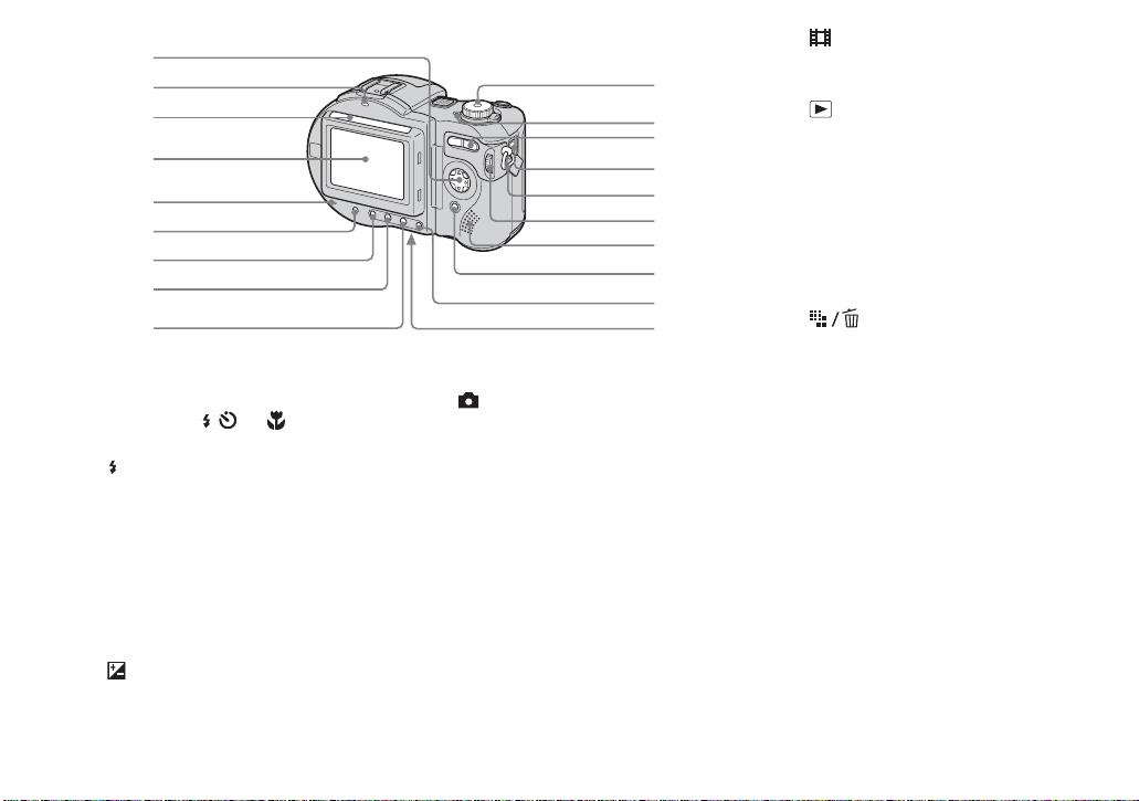
Identifying the parts
1
See the pages in parentheses for details of operati on .
2
3
4
5
6
Attaching the
shoulder strap
A Microphone
B POWER ON/OFF (CHG) switch
(15)
C Shutter button (22)
D Hologram AF emitter (29, 116)
E Self-timer lamp (27)
F Battery cover (11)
G Lens
H Tripod receptacle (bottom
surface)
7
8
9
0
qa
qs
qd
qf
qg
qh
I Flash emitter (27)
J Advanced accessory shoe (67)
K Hook for lens cap/shoulder stra p
L Disc cover OPEN lever (18)
M ACC (Accessory) jack (67)
N Lens ca p
O (USB) jack (93)
P A/V OUT (MONO) jack (34)
• Use a tripod with a screw length of less
than 5.5 mm (7/32 inch). You will be
unable to firmly secu re t h e c am era to
tripods having longer screws, and may
damage the camera.
• Use ACC jack to connect an external
flash or other equipment.
• D o not touch the microphone while
recording.
9
Page 17
1
2
3
4
5
6
7
8
9
A Control button
(Menu on) (v/V/b/B/z)
(Menu off) ( / /7/) (27, 27, 24,
26)
B /CHG (charg e) lamp (12)
C Photocell window for LCD
screen
D LCD screen
E ACCESS lamp (18)
F DISPLAY/LCD BACK LIGHT ON/
OFF button (30)
G AE LOCK button (54)
H FOCUS button (47, 50)
I (Exposure) button (51)
J Mode dial (16)
: To shoot still images in auto
adjustment mode
P: To shoot still im a ges in
programmed mode
S: To shoot in the shutter speed
priority mode
A: To shoot in the aperture
priority mode
M: To shoot in the manual
exposure mode
SCN: To shoot in the Scene
Selection mode
SET UP: To set the SET UP items
0
qa
qs
qd
qf
qg
qh
qj
qk
ql
: To shoot movies, Clip
Motion images or Multi
Burst mode images
: To view or edit images
K POWER lamp (15)
L Zoom button (for shooting) (25)/
Index button ( for viewing) (33)
M DC IN jack (11, 14)
N Hook for shoulder strap
O Jog di a l (42)
P Speaker
Q MENU button (41, 112)
R (Image Size/Delete)
button (20, 36)
S RESET button (bottom surface)
(98)
• The LCD screen automatically becomes
brighter when photocell window for LCD
screen is exposed to sunlight.
10
Page 18

Getting started
Charging the battery pack
DC IN jack cover
Getting started
DC plug
1
, Open the battery cover.
Slide the cover in the direction of the arrow.
• Be sur e to turn off your camera wh en
charging the battery pack (page 15).
• Your camera operates only with the
“InfoLITHIUM” NP-FM50 battery pack (M
series) (supplied) (page 121).
2
Battery eject lever
, Install the battery pack, then
close the battery cover .
Insert the battery pack with the b mark
facing toward the battery compartment as
illustrated.
Make sure the battery pack is firmly
inserted all the way, then close the cover.
• The battery pack is easily inserted by pushing
the battery eject lever at the front of the battery
compartment up.
3
AC Adaptor
, Open the DC IN jack cover and
connect the AC Adaptor
(supplied) to the DC IN jack of
your camera.
Connect the DC plug with the v mark
facing up.
• Do not short the DC plug of the AC Adaptor
with a metallic object, as this may cause
malfunction.
• Clean the DC plug of the AC Adaptor with a
dry cotton bud. Do not use the dirty plug. Use
of the dirty plug may not properly charge the
battery pack.
11
Page 19
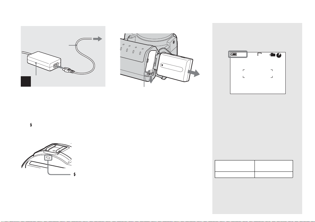
2 To wall outlet (wall socket)
Power cord
(mains lead)
1
AC Adaptor
4
, Connect the power co rd (mains
lead) to the AC Adaptor and
then to a wall outlet (wall
socket).
The /CHG lamp (orange) lights up when
charging begins, and goes off when
charging is completed.
/CHG lamp
• After charging the battery pack, disconnect the
AC Adaptor from the DC IN jack of your
camera.
To remove the battery pack
Battery eject lever
Open the battery cover. Slide the ba tt ery
eject lever in the direction of the arrow, and
remove the battery pack.
• Be careful not to drop the battery pack when
removing it.
Battery remaining indicator
The battery remaining indicator on the LCD
screen shows the remaining shooting or viewing
time.
60min
• The black portion of the battery remaining
indicator in the illustration shows the actual
remaining time.
• The displayed remaining tim e may not be
correct under certain circumstances or
conditions.
5.0M
101
4
M AF
Charging time
Approximate time to charge a completely
discharged battery pack using the AC Adaptor at
a temperature of 25°C (77°F).
Battery pack
NP-FM50 (supplied) Approx. 150
Charging time
(min.)
12
Page 20
Number of images and battery
life that can be recorded/
viewed
The tables show the approximate number of
images and th e ba ttery life that can be
recorded/viewed when you shoot images in
normal mode with a fully charged battery
pack at a temperature of 25°C (77°F). The
numbers of images that can be recorded or
viewed take into account changing the
supplied disc as necessary. No te tha t the
actual numbers may be less than indicat ed
depending on the conditions of use.
Shooting still images
Under the average conditions
Image size
5.0M Approx. 220 Approx. 110
VGA Approx. 250 Approx. 125
1)
Shooting in the following situations:
– [P. Quality] is set to [Fine]
– Shooting one time every 30 seconds
– The zoom is switched alternately between
– The flash strobes once every two times
– The power turns on and off once every ten
– [AF Mode] is set to [Monitor] in the SET
NP-FM50 (supplied)
No. of
images
the W and T ends
times
UP settings
Viewing still images
Image size
5.0M Approx. 1900 Approx. 160
VGA Approx. 2000 Approx. 170
2)
Viewing single images in order at about five
second intervals
NP-FM50 (supplied)
No. of
images
1)
Battery life
(min.)
2)
Battery life
(min.)
Shooting movies
Continuous shooting Approx. 130
3)
Shooting continuously at 160 (Mail) image
size
• The number of images and the battery life that
can be recorded/viewed are decreased under the
following conditions:
– The surrounding temperature is low
– The flash is used
– The camera has been turned on and off many
times
– The zoom is used frequently
– [LCD Backlight] is set to [Bright] in the SET
UP settings
– The battery power is low.
The battery capacity decreases as you use it
more and more and as time passes
(page 122).
– [AF Mode] is set to [Cont] in the SET UP
settings
3)
NP-FM50 (supplied)
Battery life (min.)
Getting started
13
Page 21
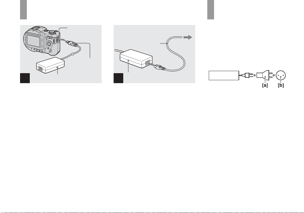
Using an external power source
DC IN jack cover
DC plug
2 To wall outlet (wall socket)
Power cord
(mains lead)
1
Using your camera
abroad
Power sources
You can use your cam era i n any coun t ry or
region with the supplied AC Adaptor within
100 V to 240 V AC, 50/60 Hz. U s e a
commercially available AC plug adaptor
[a], if necessary, depending on the design of
the wall outlet (wall socket) [b].
1
AC Adaptor
, Open the DC IN jack cover and
connect the AC Adaptor
(supplied) to the DC IN jack of
your camera.
Connect th e DC plug with the v mark
facing up.
• Connect the AC Adaptor to an easily accessible
wall outlet (wall socket) close by. If any trouble
occurs while using the adaptor, immediately
shut off the power by disconnecting the plug
from the wall outlet (wall socket).
14
AC Adaptor
2
, Connect the power cord (mains
lead) to the AC Adap to r and
then to a wall outlet (wall
socket).
• When you have finished using the AC Adaptor,
disconnect it from the DC IN jack of the
camera.
• The set is not disconnected from the AC power
source (mains) as long as it is connected to the
wall outlet (wall socket), even if the unit itself
has been turned off.
AC-L15A/L15B
• Do not use an electronic transformer (travel
converter), as this may cause a malfunction.
Page 22

Turning on/off your camera
POWER lamp
POWER
switch
, Slide the POWER switch in the
direction of the arrow.
The POWER lamp (g reen) li ghts u p and th e
power is on. When you turn on your camera
for the first time, the Clock Set screen
appears (page 16).
Turning off the power
Slide the POWER switch in the direction of
the arrow again. The POW ER lamp goes
out, and the cam era turns off.
• Do not remove the battery pack o r the
AC Adaptor with the lens portion
extended, as this may cause
malfunction.
• If you turn on the power when the mode dial is
set to , P, S, A , M, SCN or , the lens
portion moves. Do not touch the lens portion
while it is operating.
Auto power-off function
If you do not operate the camera for about
three minutes during shooting or viewing or
when performing SET UP, the camera turns
off automatically to prevent wearing down
the battery. The auto power-off function
only operates when the camer a is opera ting
using a batter y pack. The auto power-off
function a ls o will not oper ate in the
following circumstance s.
• W hen viewing movies
• W hen a connector is plugg ed into the
(USB) jack or the A/V OUT (MONO)
jack.
How to use the
control button
Spot
Center
Multi
WB
WB
Metering Mode
ISO Mode
400
200
100
Auto
WB
ISO Mode
To change the current settings of the
camera, bring up the menu or the SET UP
screen (page 41), and use the control button
to make the changes.
For each item, press v/V/b/B to select the
desired value, then press the center z or
v/V/b/B to mak e the setting.
Getting started
15
Page 23

Setting the date and time
Mode dial
1
POWER switch
2
Clock Set
2003
1
/:
/
12 00
1
OK
AM
Y/M/D
M/D/Y
D/M/Y
OK
Cancel
Clock Set
2003
1
/:
/
1
OK
12 00
Y/M/D
M/D/Y
D/M/Y
AM
Cancel
OK
3
, Set the mode dial to .
• You can also carry out this operation when the
mode dial is set to P, S, A, M, SCN, or .
• To change the date and time, set the mode dial
to SET UP, select [Clock Set] in
(page 118), and perform the procedure from
step 3.
16
(Setup 1)
1
, Slide the POWER switch in the
direction of the arrow to turn
on the power.
The POWER lamp (g reen) l ights up and the
Clock Set screen appears on t he L CD
screen.
, Select the desired date display
format with v/V on the control
button, then press z.
Select from [Y/M/D] (year/ mo nth/day),
[M/D/Y] (month/day/yea r) or [D/ M / Y ]
(day/month/year).
• If the rechargeable button battery, which
provides the power for saving the time data, is
ever fully discharged (page 120), the Clock Set
screen will appear again. When this happens,
reset the date and time, by starting from step 3
above.
Page 24

Clock Set
1
2003
/
12 00
/:
1
OK
Y/M/D
M/D/Y
D/M/Y
AM
Cancel
Clock Set
2003
/:/
OK
7
OK
Y/M/D
M/D/Y
D/M/Y
1
12 00
OK
AM
Cancel
Clock Set
2003
/:/
OK
Y/M/D
M/D/Y
10 30
D/M/Y
AM
Cancel
OK
4
7
Getting started
4
, S elec t the year, month, day,
hour or minute item you want
to set with b/B on the control
button.
The item to b e s et is indicated with v/V.
5
, Set the numeric value with v/V
on the control button, then
press z to en ter it.
After entering the number, v/V move s to
the next item. Repeat this step until all of
the items are set.
• If you selected [D/M/Y] in step 3, set the time
on a 24-hour cycle.
6
, Select [OK] with B on the
control button, then press z.
The date and time ar e entere d and th e clock
starts to keep time.
• To cancel the date and time setting, select
[Cancel] with v/V/b/B on the control button,
then press z.
17
Page 25
Shooting still image
s
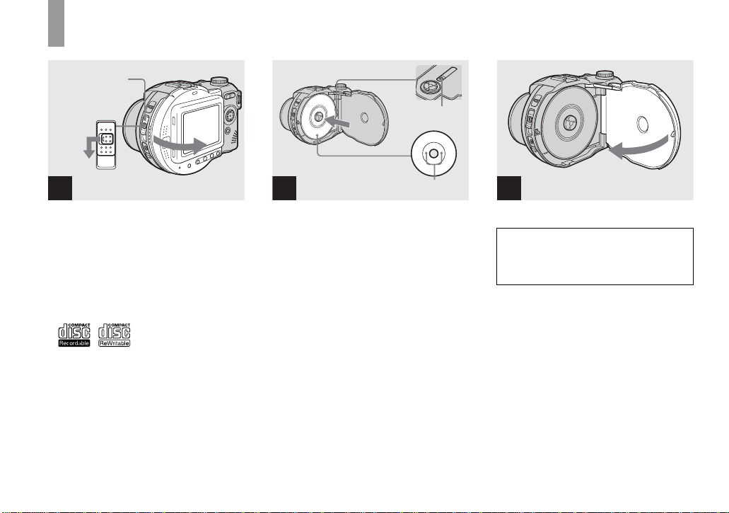
Inserting and removing a disc
Disc cover
OPEN lever
Lock tab
Pickup lens
Disc
1
, Open the disc cover.
While sliding the lock tab to the left, slide
down the disc cover OPEN lever, and open
the disc cover.
• You can use only 8 cm CD-R/CD-RW
discs that have these marks.
• For details on disc, see page 120.
18
2
Push here
, Place a di sc in t he disc tray.
Place the disc wit h the printed side up, and
push down on the center of the disc until it
clicks.
• Do not push with too force on the disc.
• Do not touch the pickup lens.
3
, Clos e th e di sc cover.
Removing the disc
Open the disc cover. Check to make sure that the
disc has completely stopped rotating, then remove
the disc.
• When the ACCESS lamp is flashing, it
means that image data is being read or
written. Never open the disc cover or
turn off the power at this time, as the
image data may be da mage d or th e d is c
may become unusable.
• While the camera is writing data on a disc, the
disc cover OPEN lever is locked.
• After you change the disc, “Repairing Data”
may appear on the LCD screen and it may take
about 10 minutes to prepare the disc for
recording depending on the disc condition.
Page 26

Initializing a disc
What is initialization?
Initialization is required to record images
on a disc.
When you perform fina li za ti on (page 85)
using your camera to view images through
a CD-ROM drive, initialization is also
automatically pe rformed, and you can
continue to reco rd images. Im ages record ed
before finalization remain on the disc.
Mode dial
1
, Insert a new disc and set the
mode dial to , then turn o n
the power.
“Initialize Place on level surface ” ap pears
on the LCD screen.
To cancel initialization
Select [Cancel] with
button, th en press
initialization , open and close the disc cover,
then perform the proce dure from step 1.
• You can also carry out this operation when the
mode dial is set to P, S, A, M, SCN or .
•
Y ou can also perform initialization using
(Disc Tool 1) in the SET UP settings
(page 117).
V on the control
z. After canceling the
Initialize
Avoid any vibration
Ready to initialize
Initialize
Avoid any vibration
Initialize in progress
2
, Select [OK] with v on the
control button, then press z.
Initialization starts. Do not shake or strike
the camera during initialization.
1
Initialize
Initialize complete
Shooting still images
19
Page 27
Setting the still image size
1
, Set the mode dial to and
turn on the power.
• You can also carry out this operation when the
mode dial is set to P, S, A, M or SCN.
5.0M
5.0M
4.5M(3:2)
3.1M
1.2M
VGA
Image Size
2
, Press (Image Size).
The Image Size setup appears.
• For details on the image size, see page 21.
VGA
5.0M
4.5M(3:2)
3.1M
1.2M
VGA
Image Size
3
, Select the desired image size
with v/V on the control button.
The image size is set.
When the setting is compl ete, pre ss
(Image Size) so that the Image Size setup
disappears from the LCD screen.
• The image size selected here is maintained even
when the power is turned off.
20
Page 28

Image size and quality
You can choose image si ze (number of
pixels) and im age quality (compression
ratio) based on the kind of images you want
to shoot. The larger yo u ma ke the image
size and the higher you make the image
quality, the better your image, but also the
larger the amount of data needed to preserve
your image. This means you can save fewer
images in your disc.
Choose an image size and qu al it y le ve l
appropriately for the kind of i mages you
want to sho o t.
You can resize the images later (Resize
function, see page 77).
You can choose image si ze from among th e
five options in the following tables. The
below image size is a minimum setting for
examples. When you want to improve
image qual ity, select th e larger image si ze.
Image size Examples
5.0M
4.5M(3:2)
3.1M
1.2M
2592×1944
2592 (3:2)
2048×1536
1280×960
Very fine prints
1)
3:2 prints
Printing A4 size images
Printing postcard size
images
VGA
640×480
1)
This option records images in a horizontal to
vertical proportion of 3:2 to match the size of
the print paper used.
Creating home pages
The number of images that can
be saved in a supplied CD-R
2)
(Units: images)
3)
Quality
Image
Fine Standard
size
5.0M 51 95
4.5M(3:2) 51 95
3.1M 81 145
1.2M 194 345
VGA 655 1285
2)
When [REC Mode] is set to [Normal]
For the number of images that can be saved in
other modes, see page 110.
3)
For more information about the image quality
mode, see page 43.
• When images recorded using earlier Sony
models are played back on this camera, the
display may differ from the actual image size.
• When the images are viewed on the LCD
screen of the camera, they all look the same
size.
• Number of shooting images can differ from
these values according to shooting conditions.
• When the number of remaining shooting
images is greater than 9999, the >9999
indicator appears on the LCD screen.
Shooting still images
21
Page 29

Basic still image shooting — Auto adjustment mode
Mode dial
1
, Set the mode dial to , and
turn on the power.
The name of the folder where th e image will
be recorded ap pears on the LCD screen for
approximately five seconds.
• This camera can create new folders and select
folders to be stored in the disc (page 43).
2 3
, Hold the camera steadily with
both hands and position the
subject in the center of the
focus frame.
The lens portion moves when you turn on
the power.
Do not cover the lens or flash with your
fingers.
• The minimum focal distance to the subject is
50 cm (19 3/4 inches). To shoot even closer
subjects, use macro recording mode (page 26).
min
60
AE/AF lock indicator
Flashes green
t Lights up
101
FINE
5.0M
96
M AF
0EV
F2.8
30
, Press and hold the shutter
button halfway down.
The beep sounds. When the AE/AF lock
indicator changes from flash ing to steadily
lit, the camera is ready for shooting.
(The LCD screen may be frozen for a split
second depending on the subjec t.)
The flash automa tically pops up and strob es
when the surroundings are da rk.
• If you release the shutter button, the recording
will be canceled.
• When the camera does not beep, the AF
adjustment is not complete. Y ou can continue to
shoot, but the AF is not set properly (except in
Continuous AF, see page 49).
• The frame appearing on the LCD screen shows
the focus adjustment range. (For more details
on the AF range finder frame, see page 47.)
22
Page 30

60
min
101
5.0M
95
M AF
4
, P ress the shutter button fully
down.
The shutter sounds. The image will be
recorded in the disc. When
lamp (page 10) goes out, you can shoot
the next image
• When operating the camera using a battery
pack, if you do not operate the camera for about
three minutes during recording, the camera
turns off automatically to prevent wearing
down the battery (page 15).
• While the image is being recorded on the disc,
the ACCESS lamp flashes. Do not shake or
strike the camera while this lamp is flashing.
Also do not turn off the power, remove the
battery pack, or open the disc cover at this time,
as the data may be damaged or the disc may
become unusable.
.
ACCESS
Mode dial for still image
shooting
When shooting still images with your
camera, you can choose from the following
shooting methods.
(Auto adjustment mode)
The focus, exposure and white balance are
automatically adjusted to allow easy
shooting. The image quality is set to [ F in e]
(page 43).
P (Program auto shoot ing)
You can set the desired shooting functions
using menus (pages 41 and 112). In
addition, you can ch ange the combination
of the F value and the shutter speed
(Program Shift, see page 45).
S (Shutter speed priority)
You can set the desired shooting functions
using menus (pages 41 and 112). In
addition, you can select the shutt er spee d
(page 46).
A (Aperture priority)
You can set the desired shooting functions
using menus (pages 41 and 112 ). In
addition, you can selec t t he a perture value
(page 47).
M (Manual)
You can set the desired shooting functions
using menus (pages 41 and 112 ). In
addition, you can manually adjust the
shutter speed and the aperture value
(page 47).
SCN (Scene selection)
You can select from the following modes to
shoot accordin g to the scene conditi ons
(page 64).
– (Twilight mode)
–
(Twilight portrait mode)
– (Landscape mode)
– (Portrait mode)
–
(Snow mode)
– (Beach mode)
Shooting still images
23
Page 31

Auto Focus
When you try to shoot a subject that is
difficult to f ocus on, the A E/AF lock
indicator changes t o flas hing slowly.
The Auto Focus function may have
difficulty working und er the following
conditions. In such cases, release the shutter
button, then recompose the shot and focus
again.
• T he subject is distant from the ca m era
and dark.
• T he contrast between the subject and its
background is poor.
• The subject is seen through glass, such as
a window.
• A fast-moving subject.
• T he subject reflects or has a lustrous
finish, such as a mirror or a luminous
body.
• A fl ashing subject.
• A backlit subject.
There are two Auto Focus functions: “AF
range finder frame” which set s the focus
position according to the su bject position
and size, and “AF mode” which sets the
focus operation according to the AF
response and the battery consumption.
See page 47 for details.
Checking the last image you
shot — Quick Review
60
min
5.0M
8/8
Review
RETURN
101
10:30
2003 7 4101-0029
PM
, Press b (7) on the control
button.
To return to the normal shooting mode,
press lightly on the shutter button or press b
(7) again.
To delete the image displayed on the
screen
1 Press (Delete).
2 Select [Delete] with v on the control
button, then press z.
The image is deleted.
24
Page 32

Using the zoom feature
min
101 101
60
VGA
x1.1
min
60
96
M AF
VGA
96
M AF
x3.0
, P re ss t he zoom button to
choose the desired zoom
position for shooting.
Minimum focal distance to the
subject
Approx. 50 cm (19 3/4 inches) from the lens
surface
• The lens portion moves during zoom operation.
Do not touch the lens portion while it is
operating.
• The zoom magnification cannot be changed
while shooting movies (page 80).
T (telephoto)W (wide-angle)
Smart zoom
Digital pr o cessing lets y ou zoom in the
image without deterioration.
When the zoom ex ceeds 3 ×, enla rgemen t is
carried out usi ng the smart zoom. When the
smart zoom is not needed, set [Smart Zoom]
to [Off] in the SET UP settings (page 116).
When you press the zoom button, the zoom
scaling indicator appears on the LCD
screen.
Zoom scaling indicator
The T side of this line shows
the extent of smart zoom
x2.5
The maximum zoom scale depends on the
image size.
[3.1M]: 3. 8×
[1.2M]: 6. 1×
[VGA]: 12×
When the image size is [5.0M] or
[4.5M(3:2)], the smart zoom does not
work.
• When using the smart zoom, the image on the
LCD screen may look rough. However, this
phenomenon has no effect on the recorded
image.
• AF range finder frame is not shown when using
the smart zoom. The AF range finder frame
indicator flashes and the centrally-located
subject has priority to focus on.
Shooting still images
25
Page 33

Shooting close-ups — Macro
60
min
101
5.0M
96
M AF
60
min
101
5.0M
95
M AF
The macro recording mode is used when
zooming up a small subject, such as flowers
or insects. You can shoot close-ups of
subjects up to the distances specified below.
When the zoom is set all the way to
the W side:
Approx. 4 cm (1 5/8 inches) from the lens
surface
When the zoom is set all the way to
the T side:
Approx. 20 cm (7 7/8 inches) from the lens
surface
26
1
, Set the mode dial to , and
press B ( ) on the control
button.
The (macro) indicator appears on the
screen.
• If the menu is currently displayed, press MENU
first so that the menu disappears.
• You can also carry out this operation when the
mode dial is set to P, S, A, M, SCN (other than
(Twilight mode) or ( Landscape mode),
see page 64) or .
2
, Center the subjec t in the frame,
and press the shutter button
fully down.
To return to normal recording mode
Press B ( ) on the control button again.
The indicator disappears.
Page 34

Using the self-timer
60
min
101
5.0M
96
M AF
Selecting a flash mode
60
60
min
FINE
101
5.0M
96
M AF
0EV
F2.8
30
min
101
5.0M
96
M AF
Shooting still images
1
, T urn the mode dial to , and
press V ( ) on the con tro l
button.
The (self-timer) indicato r appears on the
LCD screen.
• If the menu is currently displayed, press MENU
first so that the menu disappears.
• You can also carry out this operation when the
mode dial is set to P, S, A, M, SCN or .
2
, Center the subject in the frame,
and press the shutter button
fully down.
The self-timer lamp (page 9) flashes and a
beep sounds after you press the shutter
button until the shutter operates
(approximately 10 seconds).
To cancel the self-timer in the middle
of the operation
Press V ( ) on the control button again.
The indicator disappears from the LCD
screen.
• If you press the shutter button while standing in
front of the camera, the focus and the exposure
may not be correctly set.
, Set the mode dial to , and
press v ( ) on the control
button repeatedly to sele ct a
flash mode.
Each time you press v ( ), the indicator
changes as follows.
27
Page 35

No indicator (Auto): The flash
automatically pops up and strobes when the
surroundings are dark.
r
(Forced flash): The flash strobes
regardless of the surrounding brightness.
r
(Slow synchro): The flash strobes
SL
regardless of the surrounding brightness.
The shutter sp eed is sl ow in a dark place, s o
you can clearly shoot the background that is
out of flash light.
r
(No flash): The flash does not strobe.
• If the menu is currently displayed, press MENU
first so that the menu disappears.
• You can also carry out this operation when the
mode dial is set to P, S, A, M, SCN (
(Portrait mode)) or (Clip Motion).
• The recommended shooting distance using the
flash is approximately 0.5 m to 5.0 m (19 3/4
inches to 196 7/8 inches) (when [ISO] is set to
[Auto]).
• You can change the brightness of the flash with
[Flash Level] in the menu settings (page 113).
(You cannot change the brightness of the flash
while the mode dial is set to .)
• When using the (Slow synchro) or (No
flash) mode, the shutter speed becomes slower
in dark places, so using a tripod is
recommended.
•
While charging the flash, the /CHG lamp
flashes. After the charging is complete, the
lamp goes out.
• When you press the shutter button halfway
down while the flash is strobing, the / C HG
lamp turn s on .
• You can mount an external flash on this camera
(page 67).
• Attaching a conversion lens (not supplied) may
block the light from the built-in flash or cause
the lens shadow to appear.
• This setting is maintained even when the power
is turned off.
SL
To reduce the red-eye
phenomenon when shooting
live subjects
Set [Red Eye Reduction] to [On] in the SET
UP settings (page 116). indicator
appears on the LCD scre en, and the flash
pre-strobes before shooting to redu ce the
red-eye phenomenon.
m
• Red-eye reduction may not produce the desired
effects depending on individual differences, the
distance to the subject, if the subject does not
see the pre-strobe, or other conditions.
28
Page 36

Recording images with the
N
hologram AF
The hologram AF is fill light to focus more
easily on a subject in dark surroundings.
When not using this function, set
[Hologram AF] to [Off] in the SET UP
settings (page 116).
appears on the screen and the hologram
O
AF emits red light when the shutt er bu tton
is pressed hal f w ay until the focus is locked.
FINE
60
min
ON
101
5.0M
96
M AF
0EV
F2.8
30
• If hologram AF light does not reach the subject
sufficiently or the subject has weak contrast,
focus will not be achieved. (An approximate
distance of 0.5 m to 4.0 m (19 3/4 inches to 13
feet 1 3/8 inches) is recommended.)
• Focus is achieved as long as hologram AF light
reaches the subject, even if the light is slightly
off the center of the subject.
• When the focus preset distance is set (page 50),
the hologram AF does not function.
• When [Conversion Lens] is set to [On] in the
SET UP settings (page 117), the hologram AF
does not function.
• If the hologram AF emitter is dirty, the
hologram AF light may be dimmed and focus
may not be achieved. In this case, wipe the
hologram AF emitter with a dry cloth.
• The hologr a m AF emitte r emits very bright
light. Although there are no problems with
safety, directly looking into the hologram AF
emitter at close range is not recommended.
• Do not block the hologram AF emitter during
recording.
• The AF range finder frame is not displayed. AF
range finder frame indicator flashes and the
centrally-located subject has priority to focus
on.
• The hologram AF does not function when SCN
is set to
(Twilight mode) or
(Landscape mode).
About Hologram AF
“Hologram AF (Auto-Focus)” is an AF fill
light system that applies laser holograms to
enable you to s h o ot still imag es in dark
places. The Hologram AF system uses
gentler radiation than co nventional highbrightness LEDs or lamps, thus satisfying
Laser Class 1* specifications and
maintaining higher safe ty for human eyes.
* Hologram AF satisfies Class 1 (time base
30 000 seconds), specified in JIS (Japan), IEC
(EU), and FDA (US) industry standards.
Complying with these standards identifies the
laser product as safe, under the condition that a
human can look at the laser light either directly
or focused through a lens for 30 000 seconds.
Shooting still images
29
Page 37

Indicators on the screen during shooting
DISPLAY/LCD BACK LIGHT ON/OFF
Each time you press DISPLAY/LCD
BACK LIGHT ON/OFF, the d isplay
changes in the following ord er.
Indicators on
60min
5.0M
r
Histogram on
60min
r
Indicators off
r
Backlight off
• For a detailed description of the indicators, see
page 125.
• For a detailed description of the histogram, see
page 52.
M AF
101
96
• The setting selected here is maintained even
when the power is turned off.
101
5.0M
96
M AF
M AF
30
Page 38

Inserting the date and time on a still image
Camera 1
1
Moving Image :
2
AF Mode :
1
Smart Zoom :
Date/Time :
2
Red Eye Reduction :
1
Hologram AF :
2
SELECT
MPEG Movie
Monitor
On
Off
Off
Auto
1
, S et the mo de dial to SET UP.
The SET UP screen appears.
• When images are shot with the date and time
superimposed, the date and time cannot be
removed later.
• The date and time do not appear on the LCD
screen during shooting, instead, “ ” appears
in the upper left corner of the LCD screen. The
actual date and time appear in red during
playback only.
Camera 1
1
Moving Image :
2
AF Mode :
1
Smart Zoom :
Date/Time :
2
Red Eye Reduction :
1
Hologram AF :
2
OK
Day&Time
Date
Off
2
, Sel ect (Camera 1) with v on
the control button, then press
B.
Select [Date/Time] with v/V,
then press B.
• If you select [Date], the date is superimposed
onto the image in the order selected in “Setting
the date and time” (page 16).
1
Camera 1
1
Moving Image :
2
AF Mode :
1
Smart Zoom :
Date/Time :
2
Red Eye Reduction :
1
Hologram AF :
2
PAGE SELECT
MPEG Movie
Monitor
On
Date
Off
Auto
3
, Select the date and time setting
with v/V on the control button,
then press z.
Day & Time: Superimposes the date, hour,
and minute onto the image.
Date: Superimposes the year , mont h and
day onto the image.
Off: Does not superimpose the date and
time onto the image.
After the setting has been compl eted, set the
mode dial to , and shoot the im a g e.
• You can also superimpose the date and time
with the mode dial set to P, S, A, M or SCN.
• This setting is maintained even when the power
is turned off.
Shooting still images
31
Page 39

Viewing still image
s
Viewing images on the LCD screen of your
camera
Single (single-image)
screen
60min
VGA
101
8/9
Index (nine-image)
screen
Index (triple-image)
screen
Viewing single images
60min
VGA
101
8/9
10:30
2003 7 4101-0008
BACK/NEXT VOLUME
PM
You can view imag es shot with yo ur camera
almost immediately on the LCD screen.
You can select the following three methods
for viewing images.
Single (single-image) screen
You can view one image at a time,
displayed over the entire screen.
Index (nine-image) screen
Nine images are displayed simultaneously
in separate panels on the screen.
Index (triple-image) screen
Three images are displayed simultaneously
in separate panels on the screen. Various
image information items are also displayed.
• You can switch the displayed image to the
previous image or the next image by rotating
the jog dial (page 42).
32
Aperture Value:
Shutter Speed:
Exposure Value:
ISO:
MOVESINGLE DISPLAY
SINGLE DISPLAY
• For a detailed description of the screen
indicators, see page 125.
• For details on movies, see page 81.
F2.8
1/30
0.0
100
10:30
BACK/NEXT
PM
2003 7 4101-0002
BACK/NEXT
10:30
VOLUME
PM
2003 7 4101-0008
1
, Set the mode dial to , and
turn on the power.
The last image in the select ed rec ording
folder (page 43) appears on the screen.
Page 40

Viewing an index screen (nine-image or triple-image)
60min
VGA
101
3/9
2003 7 4101-0003
BACK/NEXT VOLUME
10:30
Aperture Value:
Shutter Speed:
Exposure Value:
ISO:
PM
MOVESINGLE DISPLAY
SINGLE DISPLAY
2003 7 4101-0002
F2.8
1/30
0.0
100
BACK/NEXT
10:30
PM
Viewing still image s
2
, S elect the desired still image
with b/B on the control button.
b : To display the preceding image
B : To display the next imag e
, Pre ss t h e zoom W (index)
button once.
The displa y s w itches to the Index (nineimage) screen.
To display the next (previous) index
screen
Press v/V/
b/B on the control button to
move the yellow frame up /down/left/right.
, Press the zoom W (index)
button once more.
The display switches to the Index (tripleimage) screen.
Press v/V on the control button to display
the remaining image information.
To display the next (previous) index
screen
b/B on the control button.
Press
To return to the single-image screen
Press the zoom T repeatedly, or press z on
the control button.
33
Page 41

Viewing images on a TV screen
A/V
connecting
cable
(supplied)
1
A/V OUT (MONO) jack
2
TV/Video switch
VGA
101
2/9
10:30
PM
2003 7 4101-0002
BACK/NEXT VOLUME
3
, Connect the supplied A/V
connecting cable to the A/V
OUT (MONO) jack of the
camera and the audio/vid eo
input jacks of the TV.
If your TV has stereo input jacks, connect
the audio plug (black) of the A/V
connecting cable to the Lch jack.
• Turn off both your camera and the TV before
connecting the camera and the TV with the A/V
connecting cable.
• We recommend using the AC Adaptor
(supplied) to prevent the power from turning off
partway.
34
, Turn on the TV and set th e TV/
Video switch to “Video”.
• The name and location of this switch may differ
depending on your TV. For details, see the
operating instructions supplied with the TV .
, Set the mode dial to , and
turn on the camera.
Press b/B on the control button to select the
desired image.
• When using your camera abroad, it may be
necessary to switch the video output signal to
match that of your TV system (page 118).
Page 42

Viewing images on a TV screen
If you want to view images on a TV screen,
you need a TV with a vid eo input jack and
the A/V connecting ca ble (supplied).
The color system of the TV must ma tch that
of your digital still camera. Chec k the
following lists:
NTSC system
Bahama Islands, Bolivia, Canada, Central
America, C h ile, Colombia, Ecuador,
Jamaica, Japan, Korea, Mexico, Peru ,
Surinam, Taiwan, the Ph ilippines, the
U.S.A., Venezuela, etc.
PAL system
Australia, Austria, Belg iu m, Ch ina, Czech
Republic, Denmark, Finland, Germany,
Holland, Hong Kong, Italy, Kuwait,
Malaysia, New Zealand, Norway, Portugal,
Singapore, Slovak Republi c, Spa in,
Sweden, Switzerland, Thailand, United
Kingdom, etc.
PAL-M system
Brazil
PAL-N system
Argentina, Paragua y, Ur uguay
SECAM system
Bulgaria, France, Guian a, H unga ry, Iran,
Iraq, Monaco, Poland , Russ ia, Ukr aine , etc.
Viewing still image s
35
Page 43

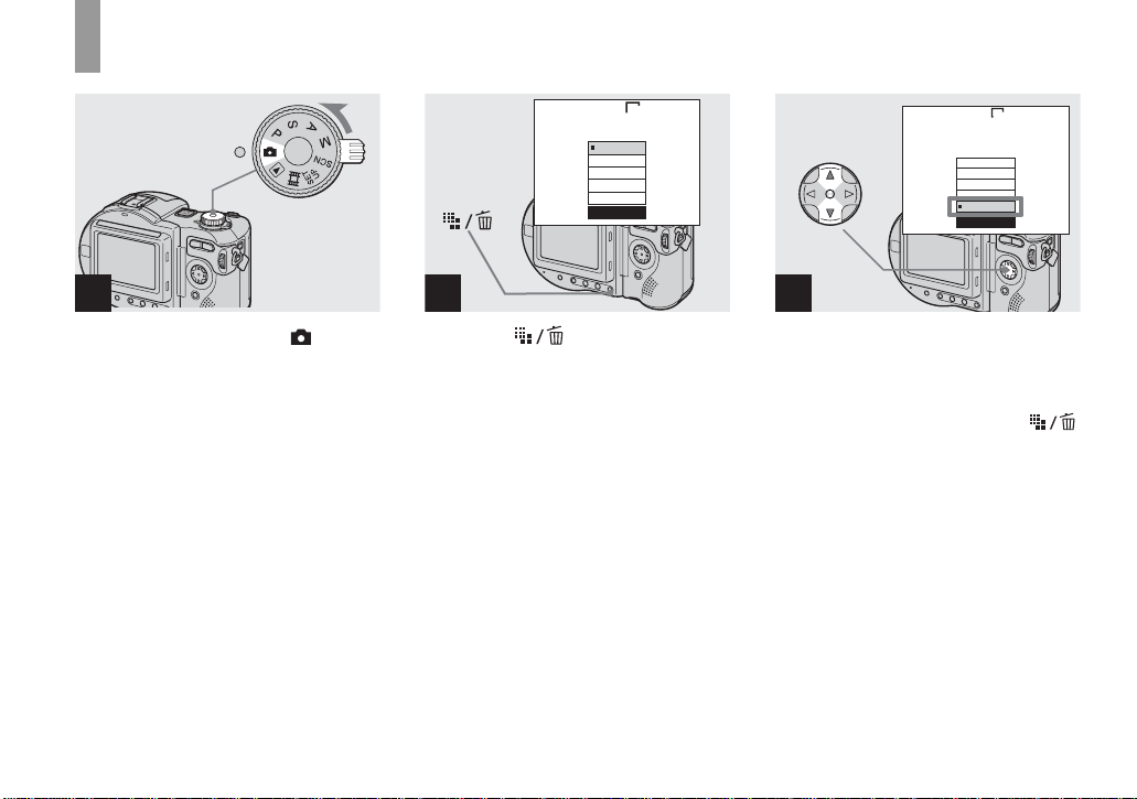
Deleting images
Deleti
till i
s
60
min
VGA
101
2/9
ng s
60
min
VGA
101
2/9
mage
60
min
VGA
101
2/9
10:30
2003 7 4101-0002
BACK/NEXT VOLUME
PM
1
, Set the mode dial to , and
turn on the camera.
Press b/B on the control
button to select the image you
want to delete.
• When using a CD-R, the disc remaining space
does not increase even if you delete images.
• When using a CD-RW, the disc remaining
space increases only if you delete the last
image you shot while is indicated on the
LCD screen. If you modify an image, or open
and close the disc cover, disappears.
• If the disc remaining space is not sufficient, you
may not be able to delete the image.
• It ma y take some tim e to delete the ima ges.
36
Delete
BACK/NEXTOK
Exit
2
, Press (Delete).
The image has not yet been deleted at this
point.
• You cannot delete the protected image
(page 75).
Delete
Exit
Select
Delete
Exit
All In Folder
BACK/NEXTOK
3
, Select [Delete] with v on the
control button, then press z.
When the message “Disc access”
disappears, the image has been deleted.
To continue and delete other images
Display the image to be de leted with
on the control button. Then, select [Delete]
v and press z.
with
To cancel deleting
Select [Exit] with V on the control button,
then press z.
b/B
Page 44

Deleting images in index (nine-image) mode
Select
Delete
Exit
All In Folder
Delete
Select
Exit
All In Folder
TO NEXTMOVESELECT
1
, W hile an index (nine-image)
screen (page 33) is displayed,
press (Delete).
2
, Select [Select] with b/B on the
control button, then press z.
To delete all the images in the folder
Select [All In Folder] with B on the control
button, th en press z. Se lect [OK], the n
press z. All of the unprotected images in
the folder are deleted. To cancel deleting,
select [Cancel], then press z.
3
Deleting still images
, Select an image you want to
delete with v/V/b/B on the
control button, then press z.
The green indicator appears on the
selected image. At this point, the image has
not yet been deleted. Repeat this step for all
of the images you want to delete.
• To cancel a selection, press z again so that the
indicator disappears.
37
Page 45

Deleting images in index (triple-image) mode
Exit
Delete
4
, Press (Delete) and select
[OK] with B on the control
button, then press z.
When the message “Disc access”
disappears, the images have been deleted.
To cancel deleting
Select [Exit] with b on the control button,
then press z.
38
2003 7 4101-0002
F2.8
1/30
0.0
100
BACK/NEXT
10:30
Delete
Exit
10:30
PM
2003 7 4101-0002
BACK/NEXTOK
PM
2
, Press (Delete).
The image has not yet been deleted at this
point.
Aperture Value:
Shutter Speed:
Exposure Value:
ISO:
OK
SINGLE DISPLAY
1
, While an index (triple-image)
screen (page 33) is displayed,
set the image you want to
delete to the center with b/B on
the control button.
Page 46

BACK/NEXTOK
Delete
Exit
2003 7 4101-0002
10:30
Formatting a CD-RW
Disc Tool 1
1
Finalize:
2
Format:
1
Initialize:
Unfinalize:
2
1
PM
2
OK
OK
Cancel
3
, S el ect [Delete] with v on the
control button, then press z.
When the message “Disc access”
disappears, the image has been del eted.
To cancel deleting
Select [Exit] with V on th e control button,
then press z.
1
, Place t h e CD - RW you want to
format in the disc tray.
Set the mode dial to SET UP,
and turn on the camera.
• A CD-R cannot be formatted.
• Formatting is performed to delete all the images
on the CD-RW or to use a CD-RW formatted
with other equipment than this camera.
• When you format a CD-RW, all data
stored on the disc including protected
images will be deleted. The CD-RW is
also automatically initialized after
formatting.
2
, Select (Disc Tool 1) with v/
V on the control button, then
press B. Select [Format] with
v/V, then press B.
• We recommend using the AC Adaptor to
prevent the power from turning off partway
through the formatting.
1
Deleting still images
39
Page 47

Format
Place on level surface
All data will be erased
OK
Ready?
O K
Cancel
Format
Avoid any vibration
Format in progress
3
, Select [OK] with v on the
control button, then press z.
“Format Place on leve l su rf ace” ap pear s on
the LCD screen.
To cancel formatting
Select [Cancel] with V on the control
button, th en press z.
40
4
, Select [OK] with v, then press
z.
When the message “Format in prog ress”
disappears, formatting has been completed.
• It may take some time to for mat a CD-RW.
• A CD-RW can be formatted about 300 times.
• A CD-RW formatted using other equipment
than this camera cannot be used with this
camera. Format the disc again with this camera.
Page 48

Bef
ore advanced operation
s
How to setup and
operate your camera
The usage of the menus and SET UP screen
items that are most frequently used for
“Advanced operati ons” is described below.
Control
Mode dial
button
MENU
Changing the menu settings
a Press MENU.
The menu appears.
Spot
Center
Multi
WB
Metering Mode
ISO
Mode
b Press b/B on the control
button to select the item you
want to set.
The selected item turns yellow.
FINE
Fine
Standard
WB
ISO Mode
P.Quality
c Press v/V on t he control
button to select the desired
setting.
The frame of the selected setting turns
yellow, and the setting is entered .
To turn off the menu display
Press MENU.
Changing the items in the
SET UP screen
a Set the mode dial to SET UP.
The SET UP screen appears.
Camera 1
1
Moving Image :
2
AF Mode :
1
Smart Zoom :
Date/Time :
2
Red Eye Reduction :
1
Hologram AF :
2
SELECT
MPEG Movie
Monitor
On
Off
Off
Auto
b Press v/V/b/B on the control
button to select the item you
want to set.
The frame of the selected item turns
yellow.
Setup 1
1
LCD Brightness:
2
LCD Backlight:
1
Beep:
Language:
2
Clock Set:
1
2
OK
OK
OK
Cancel
c Press z on the control button
to enter the setting.
To turn off the SET UP screen
display
Set the mode dial to anything other than
SET UP.
Before advanced operations
41
Page 49

How to use the jog dial
The jog dial is used to change the setting
values when shooting with the manual
adjustment modes (shutter speed prio r ity
mode, aperture priority mode, manual
exposure mode), EV adjustment, focusing
manually or choosing AF rang e finder
frame.
Mode dial
To select the item
a Turn the jog dial to select the
item you want to set.
Move the yellow indication b to select
the item.
min
60
M
101
FINE
5.0M
4
M AF
0EV
F5.6
50
b Press the jog dial.
The value turns y ellow.
min
60
M
101
5.0M
FINE
4
M AF
0EV
F5.6
50
To select the value
You can select values that are displayed in
yellow.
Turn the jog dial to select the value
you want to set
The displaye d value is set.
42
Select Set
Jog dial
c To set other items, press the
jog dial and then perform the
following operations.
• Items that cannot be selected are displayed as
gray.
Page 50

Deciding the still
image quality
Mode dial: P/S/A/M/SCN
You can select the still image quality from
[Fine] or [Standard].
Mode dial
a Set the mode dial to P, S, A, M
or SCN.
b Press MENU.
The menu appears.
Control button
MENU
c Select (P. Quality) with b/B,
then select the desired image
quality with v/V.
FINE
Fine
Standard
WB
P.Quality
ISO Mode
• This setting is maintained even when the power
is turned off.
• You can also carry out this operation when the
mode dial is set to
(Multi Burst) (page 60).
Creating or selecting
a folder
Mode dial: SET UP
Your camera can create multiple folders
within a disc. You can select the folder used
to store images.
When not creating a new folder,
“101MSDCF” folder is selected as the
recording folder.
You can create folders up to “999MSDCF.”
Mode dial
• Up to 4000 images can be stored in one folder.
When the folder capacity is exceeded, a new
folder is automatically created.
Control button
MENU
Before advanced operations
43
Page 51

Creating a new folder
a Set the mode dial to SET UP.
b Select (Disc Tool 2) with
2
v/
V, [Create REC. Folder] with B/
v/V, and [OK] with B/v, then
press
z.
The following screen appears.
60min
Create REC. Folder
Creating REC. Folder 102MSDCF
Ready?
O K
OK
Cancel
c Select [OK] with v, then press
z.
A new folder is c r eated with a number
one higher than the largest number in
the disc, a nd the folder be comes the
recording folder.
To cancel folder creation
Select [Cancel] in step 2 or 3.
• Once you create a new folder, you ca nnot delete
the new folder with the camera.
• Images are recorded in the newly created folder
until a different folder is created or selected.
Changing the recording
folder
a Set the mode dial to SET UP.
b Select (Disc Tool 2) with
2
v/
V, [Change REC. Folder] with
B/v/V, and [OK] with B/v, then
press
z.
The recording fo l der selectio n screen
appears.
Select REC. Folder 2/2
102
Folder Name:
102MSDCF
No. Of Files:
0
Created:
2003 7 4
AM
1:05:34
O K
OK BACK/NEXT
Cancel
c Select the desired folder with
b/B, and [OK] with v, then
press z.
To cancel changing the
recording folder
Select [Cancel] in step 2 or 3.
• You cannot select the “100MSDCF” folder as a
recording folder.
• The image is stored in the newly selected
folder. You cannot move images to a different
folder with this camera.
44
Page 52

Advanced still image shoot in g
Shooting with
Program Shift
— Program Shift
Mode dial: P
Program Shift lets you quickly change the F
value (aperture value ) and shutter speed
combination while ke eping the brightness
fixed.
.
Shutter
Mode dial
60
min
P
101
FINE
5.0M
96
M AF
F5.6
800
60
min
P
Jog dial
5.0M
FINE
101
96
M AF
0EV
F8.0
400
a Set the mode dial to P.
b Shift the F value and shutter
speed combination.
Select the F value and shutter speed
combination with the jog dial
(page 42). is indicated.
• You cannot shift the F value and shutter speed
combination when the shutter button is pressed
halfway down.
• When the brightness changes, the F value and
shutter speed also change.
Shooting with the
manual adjustments
Mode dial: S/A/M
You can manually adjust the shutter speed
and aperture values according to the
purpose of shooting.
min
60
M
Mode dial Description
S Shutter speed priority mode.
A Aperture priority mode. Other
M Mode for manually adjusting
101
FINE
5.0M
4
Aperture
M AF
0EV
value
F3.5
50
Shutter speed
value
Other settings are
automatically adjusted to attai n
correct exposure according to
the brightness of the subject.
settings are automatically
adjusted to attain correct
exposure according to the
brightness of the subject.
both the shutter spe ed and
aperture values to achieve the
desired shooting condition.
Advanced still image shooting
45
Page 53

• You cannot make manual adjustments when
shooting movies.
• If the proper exposure is not obtained after
making the settings, the setting value indicators
on the screen may flash when the shutter button
is pressed halfway down. You can shoot in this
condition, but we recommend that you adjust
the flashing values again.
• The auto flash function does not operate.
• You can adjust an exposure value when the
mode dial is set to S or A (page 51).
Shutter speed priority mode
This function lets you shoot a fast- mo vi ng
subject with its motion frozen, or the flow
motion of a moving subject.
60min
S
101
5.0M
FINE
M AF
0EV
F5.6
1000
60min
4
S
101
5.0M
FINE
4
M AF
0EV
F5.6
8”
NR slow shutter
The NR slow shutter function removes noise
from recorded images, providing clear
images. When using a shutter speed of 1/6
second or slower, the NR slow shutter
function activates automatically and “NR”
appears before the shutter speed indication.
Press the shutter
button fully down.
46
Mode dial
Jog dial
1/1000 s (shortest) 8 s (longest)
a Set the mode dial to S.
b Select a shutter speed value.
Select a shutter speed with the jog dial
(page 42). The shutter speed can be
selected from 1/1000 to 8 seconds.
If you select a shutter speed of
1/6 secon d or slower, NR slow shutter
function is automatically activated.
• Shutter speeds of one second or longer are
indicated with ["] after the value, such as 1".
r
Then the screen
Capturing
turns black.
r
Finally, when
Processing
“Processing”
disappears, the
image has been
recorded.
• To eliminate the effects of vibration, use
of a tripod is recommended.
• When a slow shutter speed is set,
processing may take some time.
Page 54

Aperture priority mode
This function lets you change the focus
depth to bring both the subje ct and
background into focus or to shoot a subject
with a fuzzy background.
A
Aperture value F2
(minimum)
M AF
4
0EV
F5.6
160
101
5.0M
60
min
FINE
60min
A
Aperture value F8
(maximum)
AE
101
5.0M
FINE
4
M AF
0EV
F5.6
13
a Set the mode dial to A.
b Select an aperture value.
Select an aperture value with the jog
dial (page 42). The aperture value can
be selected f rom F2 to F8.
• The range of values that can be selected varies,
depending on the zoom position.
• The shutte r sp eed is aut oma tica lly a djus te d
from 1/1000 to 8 seconds.
Manual exposure mode
You can manually adjust the shutter speed
and aperture values to achieve the de sire d
shooting condition acco r d in g to your
purpose.
60
M
FINE
min
101
5.0M
4
M AF
0EV
F5.6
50
The differenc e b et w een the set value an d
the appropriate exposure determined by the
camera is displaye d on the screen as th e EV
value (page51). 0EV indicates that the
most suitable value has been set by the
camera.
a Set the mode dial to M.
b Select the shu tter sp ee d value.
Select the shutter speed value with the
jog dial (page 42).
c Select the ape rture value.
Select the aperture value with the jog
dial (page 42).
Choosing an auto
focus method
You can set the AF range fi nde r frame and
the AF mode.
AF range finder frame
The AF range fi nder fr ame sele cts the focus
position according to the su bject position
and size.
AF Mode
The AF mode sets the focus operation
according to the AF response and the
battery consumption.
Mode dial
FOCUS
Jog dial
Control button
Advanced still image shooting
47
Page 55

Choosing a focus range
finder frame
— AF range finder
Mode dial: P/S/A/M/SCN/
Multipoint AF
The camera calculates the distance in three
places to the left and right and in the center
of the image, l etting you shoot using the
auto focus function without worrying about
the image composition. This is useful when
it is difficult to fo cus on the subj ect because
it is not in the center of the frame. You can
check the positi on where the focus was
adjusted using the green fra m e.
The Multipoint AF is the factory setting.
Selected frame priority AF
You can select from five different AF range
finder frames (Center, Lef t, Rig ht , Top or
Bottom). This is useful when focusing on a
subject near t he selected fram e.
Use together with the AF loc k func tion le ts
you shoot in the desired image composition.
Spot AF
This is useful when focusing on an
extremely small subject or a narrow area.
Use together with the AF lock function lets
you shoot in the desired image composition.
Take care to hold the camera steady so that
the subject does not deviate from the range
finder frame.
a Set the mode dial to P, S, A, M,
SCN or .
b Press FOCUS to switch to AF
range finder frame sel ect.
Each time you press FOCUS, the
setting cha n ges in the foll owing order.
AF range finder frame se le ct
Y
Focus preset
c Select the desired AF range.
Select the AF range wi th the jog dial
(page 42).
You can select the AF range from
Multipoint AF, Center, Left, Right,
Bottom, Top and Spot AF.
101
60
FINE
min
5.0M
P
98
M AF
F2.8
30
AF range
finder frame
The focus is adjusted automatically.
When you press and hold the shutter
button halfway down and the focus i s
adjusted, the color of the AF range
finder frame changes from white to
green.
• When you are shooting movies (MPEG Movie)
and you choose Multipoint AF, the distance to
the center of the screen is estimated as an
average, so the AF works even with a certain
amount of vibration. Selected frame priority AF
and Spot AF automatically focus only on
selected frame, so these are convenient when
you want to focus only on what you aim at.
• When you use the smart zoom or Hologram AF,
priority AF movement is given to subjects in or
near the center of the frame. In this case, AF
range finder frame indicator flashes and the AF
range finder frame is not displayed.
48
Page 56

Choosing a focus operation
— AF Mode
Mode dial: SET UP
You can select from the fol lowing three
focus modes for your camera.
Single AF
This mode allows accurate focusing ov er a
wide range from near to distant subjects,
and is useful for shootin g s t ationary
subjects. The focus is not adjusted before
the shutter button is pressed and held
halfway down. When the shutter button is
pressed and held halfway down and AF lock
is complete, the focus is locked.
Monitoring AF
This shortens the time needed for focusing.
The camera adjusts the focus before the
shutter button is pressed and held halfway
down, letting you compose images with the
focus already adju s ted. When the shutter
button is pressed and held halfway down
and AF lock is complete, the focus is
locked. The factory setting is Monitori ng
AF.
• Battery consumption may be faster than in
Single AF mode.
Continuous AF
The camera adjusts the focus before th e
shutter button is pressed and held halfway
down, and then co ntinues to adjus t the focus
even after AF lock is comp leted. This
allows shooting of movin g subjects with
continued focus.
• The focus is not adjusted after the lock is
completed in the following cases, and the C AF
indicator flashes. The camera operates in
Monitoring AF mode.
– When shooting in the dark place
– When shooting with a slow shutter speed
• The AF range finder frame is locked to the
center.
• Focus adjustment may not be able to keep up
when shooting fast moving subjects.
• There is no lock sound when the focus is
adjusted.
• When recording with the self timer, the focus is
locked when you press the shutter button all the
way down.
• Batt ery consum ption may be faster than in any
other AF mode.
a Set the mode dial to SET UP.
b Select (Camera 1) with v,
1
[AF Mode] with B/v/V.
c Select the desired mode with
B/v/V, then press z.
• When shooting in Macro mode, the AF speed
drops in order to focus accurately on close
subjects. For quicker shooting, using a different
mode than Macro mode is recommended.
Advanced still image shooting
49
Page 57

Shooting techniques
When shooting with the subject at the edge of
the frame, the camera may focus on the center
instead of on the subject at the edge of the
frame. In a case like this, use AF l ock t o focus
on the subject, and then recompose the picture
and shoot (except in Continuous AF mode).
Compose the shot so that the subject is
centered in the AF range finder, and press the
shutter button halfway down.
When the AE/AF lock indicator stops flashing
and remains on, return to the fully composed
shot, and press the shutter button fully down.
AE/AF lock indicator
101
60
P
FINE
min
5.0M
98
M AF
0EV
AF range
F2.8
30
finder frame
m
101
60
P
• When you are using AF lock, you can
capture an image with the correct focus ev en
if the subject is at the edge of the frame.
FINE
min
5.0M
98
M AF
0EV
F2.8
30
• You can carry out the AF lock adjustment
process before you press the shutter button
fully down.
Setting the distance
to the subject
— Focus preset
Mode dial: P/S/A/M/SCN/
When shooting an image using a previously
set distance to the subject, or when shooting
a subject through a net or through w i ndow
glass, it is difficult to get the proper focus in
auto focus mo de. In these cases, u s e of the
Focus preset is convenient.
Mode dial
Jog dial
FOCUS
50
Page 58

a Set the mode dial to P, S, A, M,
SCN, or .
b Press FOCUS to switch to
focus preset.
Each time you press FOCUS, the
setting changes in the fol lowing ord er.
Focus preset
Y
AF range finder frame select
The focus is fixed and the 9 (manual
focus) indicator appears.
c Turn the jog dial to select the
desired fo cus setting.
You can select from the following
distance settings: (Units: m)
0.1, 0.2, 0.3, 0.5, 0.8, 1 . 0, 1.5, 2.0, 3.0,
5.0, 7.0, 10, 15, and ∞ (infinity)
To reactivate auto focusing
Press FOCUS agai n so that t he focus se tting
information disappea rs.
• Focus setting information is approximate, and
should be used as a reference.
• If you point the le ns up or down, the error will
increase.
• When you select 0.1 m (4 inches) with the
zoom set to the T side, you may not get a clear
focus. In such cases, the focus setting
information flashes. Press the zoom W button
until the indicator stops flashing.
• The focus preset does not work properly when
attaching a conversion lens (not supplied).
Adjusting the
exposure
— EV adjustment
Mode dial: P/S/A/SCN/
This lets you adjust the exposure value
which is set b y automatic ad justment. Yo u
can select v alues rangin g fr o m +2.0EV to
–2.0EV in steps of 1/3EV.
Mode dial
Jog dial
Advanced still image shooting
DISPLAY/LCD BACK LIGHT ON/OFF
51
Page 59

a Set the mode dial to P, S, A,
SCN or .
b Press (Exposure).
c Select the des ired exposure
value with the jog dial.
Adjust the ex po s ure value while
checking the brightness of the
background.
101
FINE
60
min
5.0M
P
98
M AF
+1.0EV
F2.8
30
To reactivate auto exposure
Return the exposure adjustment value to
0EV.
• If a subject is being shot in extremely bright or
dark conditions, or the flash is used, the
exposure adjustment may not be effective.
Shooting techniques
Normally, the camera automatically adjus ts
the exposure. If the image is too dark or too
bright as shown below, we recommend that
you adjust the exposure manually. When
shooting a back-lit subject or a subject
against a white (e.g. snowy) background,
adjust the exposure toward the + side. When
shooting a black, subject that fills the screen,
adjust the exposure toward the – side.
Underexposed
t Adjust toward +
Appropriate exposure
Displaying a histogram
A histogram is a graph showing t he
brightness o f an imag e. T he h ori zont al axis
shows the brightness, and the vertical axis
shows the number of pixels. The graph
display indicates a dark image w he n
skewed to the left side, and a brig ht im age
when skewed to the right side. The
histogram is a useful reference for checking
the exposure during recording and playback
without being affected by the brightness of
the LCD screen.
101
FINE
60
min
5.0M
P
S AF
4
0EV
BrightDark
a Set the mode dial to P, S, A, M
or SCN.
b Press DISPLAY/LCD BACK
LIGHT ON/OFF to display the
histogram.
c Adjust the exposure based on
the histogram.
52
Overexposed
t Adjust toward –
Page 60

Adjusting the exposure to the + side shifts
the histogram to the right side.
101
FINE
60
min
5.0M
P
M AF
96
0EV
Adjusting the exposure to the – side shifts
the histogram to the left side.
606060
min
P
101
5.0M
M AF
0EV
• The histogram also appears when the mode dial
is set to , but you cannot adjust the
exposure.
• The histogram also appears when you press
DISPLAY/LCD BACK LIGHT ON/OFF while
playing back a single image (page 32) or during
Quick Review (page 24).
• The histogram does not appear in the following
cases:
– When the menu is displayed
– During Quick Review of an image recorded
in Exposure Bracket mode
– When using playback zoom
– When playing back an image recorded with
the mode dial set to
• appears in the following cases:
– When recording in the smart zoom range
– When the image size is [4.5M (3:2)]
– When rotating a still image
• The histogram before recording represents the
histogram of the image displayed on the screen
at that time. A difference occurs in the
histogram before and after you press the shutter
button. When this happens, check the histogram
while playing back a single-image or during
Quick Review.
In particular a large difference may appear in
the following cases:
– When the flash strobes
– W hen [P. Effect] is set to [Solarize]
– When the shutter speed is slow or high
• The histogram may not appear for images
recorded using other cameras.
Selecting the
metering mode
Mode dial: P/S/A/M/SCN/
This function enables you t o sel ec t t he
metering mode to suit the shooting
conditions and purpose.
Multi-pattern metering ( )
The image is divided into multiple regions
and metering is performed for each region.
The camera judges the sub ject po si tion and
background brightness, and determines a
well-balanced exposure.
The camera is set to multi-pattern metering
as the factory setting.
Center-weighted metering ( )
Metering is performed with priority given
to the center of the image. The camera
determines the exposure based on the
brightness of a subject near the c ent er
accordin g to the shooting aim.
Advanced still image shooting
53
Page 61

Spot metering ( )
Light is measured only for the specific
region where the subject is lo cated. This lets
you adjust the ex p osure to the subj ect even
when the subjec t is back lit or ther e is stro ng
contrast between the subjec t and the
background.
Position the spot metering cr oss hair on one
point of the subject you want to shoo t.
Mode dial
Control button
Shooting with the
exposure fixed
— AE LOCK
Mode dial: P/S/A/SCN/
Once you press AE LOCK, the exposure is
fixed.
• When using center weighted metering or
spot metering, to focus on the same spot
as used for metering, we rec o m me nd
using the center weighted AF range
finder frame (page 48).
60min
P
FINE
101
5.0M
98
M AF
F2.8
30
Spot metering
cross hair
54
MENU
a Set the mode dial to P, S, A, M,
SCN or .
b Press MENU.
The menu appears.
c Select (Metering Mode) with
b/B, then select [Multi],
[Center] or [Spot] with v/V.
Mode dial
Shutter
AE LOCK
a Set the mode dial to P, S, A,
SCN or .
b Focus on a port ion of the
image that has the desired
exposure value, then press AE
LOCK.
Page 62

The exposure is fixed and the AE-L
indicator appears.
101
FINE
60
min
5.0M
P
M AF
98
F2.8
30
c Target the subject you want to
shoot and press and hold the
shutter button halfway down.
The focus is automatically adjusted.
d Press th e shutter button fully
down.
To release AE LOCK
Carry out one of the following s :
• Press AE LOCK again after step 2.
• Release your finger from the shu tter
button after step 3.
• Press down the shutter button in step 4.
Shooting techniques
You can shoot with the exposure locked to a
specific portion of the image.
Measure the exposure of the desired portion
of the subject using the center weighted
metering or spot metering function.
Press AE LOCK to lock the exposure, and
then recompose the picture and shoot.
Portion of the image
used to determine the
exposure
Shooting three
images with the
exposure shifted
— Exposure Bracket
Mode dial: /P/S/A/M/SCN
The camera records th r ee images in
succession, eac h w ith the exposure valu e
shifted. The exposure compensation value
can be set between ±1.0EV from the
appropriate exposure value in 1/3EV steps.
Mode dial
Shutter
Control button
MENU
Advanced still image shooting
55
Page 63

a Set the mode dial to SET UP.
The SET UP screen appear s.
b Select (Camera 2) with v/V
and [Bracket Step] with B/v,
2
then press B.
c Select the desired bracket step
value with v/V, then press z.
±1.0EV: Shifts the exposure value by
plus or minus 1.0EV.
±0.7EV: Shifts the exposure value by
plus or minus 0.7EV.
±0.3EV: Shifts the exposure value by
plus or minus 0.3EV.
d Set the mode dial to , P, S,
A, M or SCN.
e Press MENU.
The menu appears.
f Select [Mode] (REC Mode) with
b/B, then select [Exp B rk tg ]
with v/V.
g Shoot the image.
To return to normal mode
Select [Normal] in step 6.
• You cannot use the flash in this mode.
• During shooting in this mode, the images are
not displayed on the screen. Compose the
image before pressing the shutter button.
• The focus and white balance are adjusted for
the first image, and these settings are also used
for the other images.
• When the exposure is manually adjusted
(page 51), the adjusted value is used for the
center value.
• The recording interval is approximately
0.5 second.
• You cannot select a shutter speed of
1/6 second or slower.
• If the subject is too bright or too dark, you may
be unable to shoot properly with the selected
bracket step value.
56
Page 64

Adjusting color tones
— White Balance
Mode dial: P/S/A/M/SCN/
When the white balance is set to Auto, the
white balance is automatically set and the
overall color balance is adjusted according
to the shooting conditions. However, when
you shoot under fixed conditions or special
lighting conditions, you can manually
adjust the white balance.
Auto (no display)
Adjusts the white balance automatically
(Daylight)
Shooting outdoors, shooting night scenes,
neon signs, fireworks or sunrises, or
shooting just before and after sundown
(Cloudy)
Shooting under a cloudy sky
(Fluorescent)
Shooting under fluorescent lighting
(Incandescent)
• P laces where th e lighting conditions
change quickly
• Under bright lighting such as
photography studios
(Flash)
WB
Adjusts the white balance only to the flash
conditions
(One push)
For adjusting the white bala nce depending
on the light source
Mode dial
Control button
MENU
a Set the mode dial to P, S, A, M,
SCN or .
b Press MENU.
The menu appears.
c Select [WB] (White Bal) with b/
B, then select the desir ed
setting with v/V.
To reactivate auto adjustment
Select [Auto] in step 3.
• Under fluore scent lights that flicker, the white
balance adjustment function may not work
correctly even though you select
(Fluorescent).
• When the flash str obes , the ma nual setting is
canceled, and the image is recorded in [Auto]
mode (except in (Flash) mode or
(One push) mode).
WB
To shoot in one-push white
balance mode
1 Select [ ] (One push).
The indicator appears.
2 Frame a white object such as a piece of
paper filling the screen under the sam e
lighting conditions as you will shoot the
subject.
v.
3 Press
The indicator flas he s quic kly.
When the white balance has been
adjusted an d stored in th e memory, th e
indicator stops flashing.
• The indicator means:
Slow flashing: The white balance is not set or
was not able to be set.
Quick flashing: The white balance is being
adjusted (after you press
Lit steady: The white balance has been set.
• Do not shake or strike the camera during quick
flashing the indicator.
• If the indicator keeps flashing even when
you press
v, record in automatic white balance
mode.
v).
Advanced still image shooting
57
Page 65

• When you select the one-push white balance
mode, the screen momentarily turns blue.
• Wh en flash mode is set to
SL
(Slow synchro), the white balance is
adjusted to the condition with the flash
emitting.
Shooting techniques
The subject coloring is affected by the
lighting conditions. For example, the entire
image appears blue under sunlight in the
summer, and white items gain a reddish tint
under incandescent light bulbs, etc. The
human eye can resolve these problems, but
digital still cameras cannot recognize the
correct colors without adjustments.
Normally, the camera makes these
adjustments automatically, but if recorded
image colors appear unnatural, we
recommend that you adjust the white
balance.
(Forced flash) or
Adjusting the flash
level
— Flash Level
Mode dial: P/S/A/M/SCN
You can adjust the amou nt of flash light.
Mode dial
Control butto n
MENU
a Set the mode dial to P, S, A, M
or SCN.
b Press MENU.
The menu appears.
c Select [ ] (Flash Level) with
b/B, then select the desired
setting with v/V.
High: Makes the flash level higher
than normal.
Normal: Normal setting.
Low: Makes the flash level lower than
normal.
• You can carry out this operation even when the
mode dial is set to (Clip Motion).
58
Page 66

Shooting multiple
frames
Before operation
Set [Moving Image] to [Clip Motion] in the
SET UP settings (pages 41 and 116).
d Shoot the image for th e first
frame.
— Clip Motion
Mode dial:
You can shoot a number of consecutive still
images (GIF animation). The GIF format
has a small file size, making it co nvenient
for creating home pages or attaching images
to e-mail.
• Due to the limita tions of the GIF for ma t, the
number of colors for Clip Motion images is
reduced to 256 colors or less. Therefore, the
image quality may deteriorate for some images.
Normal (160×120)
Clip Motion of up to 10 frames can be
recorded. This is suitable for use on home
pages, etc.
Mobile (120×108)
Clip Motion of up to two frames can be
recorded. This is suitable for use with
portable data terminals.
• The file size is reduced in Mobile mode, so the
image quality deteriorates.
Mode dial
Shutter
Control button
a Set the mode dial to .
b Press (I mage Size ).
The Image Size setup appears.
c Select the desired mode with
v/V.
You can select from [Normal] or
[Mobile].
Making “Clip Motion”
e Shoot the image for the next
frame.
Press the shutter button to shoot the
next frame, then repeat this operation
until you have shot the desired number
of frames.
f Press z.
All the frame im ages are recorded on
the disc.
To delete some or all of the
frame images while making a
Clip Motion recording
1 Press b (7) in step 4 or 5.
The frame images you shot are played
back in turn and stop at the last image.
2 Press (Delete), and select
[Delete Last], or [Delet e All ] wit h b/B,
then press z.
Advanced still image shooting
59
Page 67

3 Select [Delete] with v, then press z.
When [Delete Las t] is s electe d in st ep 2,
each time you repeat steps 1 through 3,
the last frame you shot is deleted.
• Note that all images are not recorded on the
disc until you carry out step 6.
• For the number of images that can be recorded
in Clip Motion, see page 111.
• The date and time are not superimposed onto
Clip Motion images.
• When viewing an image recorded in Clip
Motion on the index screen, the image may
appear different from the actual image.
• GIF files not created on this camera may not be
displayed correctly.
Shooting in Multi
Burst mode
— Multi Burst
Mode dial:
This mode records 16 frames in succession
each time you press the shutter button. This
is convenient for chec king your form in
sports, for example.
Before operation
Set [Moving Image] to [Multi Burst] in th e
SET UP settings (pages 41 and 116).
Mode dial
Shutter
Control button
MENU
a Set the mode dial to .
b Press MENU.
The menu appears.
c Select (Interval) with b/B,
then select the desired fr am e
interval with v/V.
You can choose the frame interval
from the menu settings (page41).
1/30"
1/7.5
1/15
1/30
IntervalWB PFX
60
Page 68

d Sho ot the imag e.
The 16 frames are recorded as a si n gle
image (image size: 1.2M).
• See page 73 to play back images recorded in
Multi Burst mode using this camera.
• For the number of images that can be recorded
in Multi Burst mode, see page 111.
• You cannot use the flash in this mode.
• Date and time cannot be superi mpos e d onto
images.
Shooting three
images continuously
— Burst 3
Mode dial: /P/S/A/M/SCN
This mode is used for continuous shooting.
Each time you press the shutter butto n in
this mode, the camer a recor ds t hree im ages
in succession.
Mode dial
Shutter
Control button
a Set the mode dial to , P, S,
A, M or SCN.
b Press MENU.
The menu appears.
c Select [Mode] (REC Mode) with
b/B, then select [Burst 3] with
v/V.
TIFF
Voice
E-Mail
Exp Brktg
Burst 3
Normal
REC Mode
d Shoot the image.
When the “Recording” indication
disappears, you can shoot the next
image.
Advanced still image shooting
MENU
To return to normal mode
Select [Nor mal] in step 3 .
• You cannot use the flash in this mode.
• During shooting in this mode, the images are
not displayed on the screen. Compose the
image before pressing the shutter button.
• The recording interval is approximately
0.5 second.
• You cannot select a shutter speed of
1/6 second or slower.
61
Page 69

Shooting still images
in TIFF mode
— TIFF
Mode dial: /P/S/A/M/SCN
This mode records an image without
compression, so the image quality does not
deteriorate. Images recorded in this mode
are suitable for edi ti n g on a computer, etc.
Mode dial
Control button
When the “Recording” indication
disappears, you can shoot the next
image.
To return to normal mode
Select [Nor mal] in step 3 .
• JPEG images are also recorded in the image
size selected by the (Image Size) menu
(page 20). Uncompressed (TIFF) images are
recorded in [5.0 M] size except when [4.5M
(3:2)] is selected.
• Writing data takes mo re time tha n in no rmal
recording mode.
• For the number of images you can record in
TIFF mode, see page 110.
Shooting still images
for e-mail
— E-Mail
Mode dial: /P/S/A/M/SCN
In E-mail mode, a small-size image
(320×240) that is suitable for e-mail
transmission is also recorded at the same
time as recording a n ormal st ill imag e. (See
page 20 for the normal still image sizes.)
Mode dial
Shutter
Control button
MENU
a Set the mode dial to , P, S,
A, M or SCN.
b Press MENU.
The menu appears.
c Select [Mode] (REC Mode) with
b/B, then select [TIFF] with v.
d Shoot the image.
62
MENU
a Set the mode dial to , P, S,
A, M or SCN.
b Press MENU.
The menu appears.
Page 70

c Select [Mode] (REC Mode) with
b/B, then select [E-Mail] with
v/V.
d Sho ot the imag e.
When the “Recording” indication
disappears, you can shoot the next
image.
To return to normal mode
Select [Normal] in step 3.
• For instructions on how to attach images to an
e-mail message, consult the User’s Manual for
your e-mail software.
• For the number of images you can record in
E-mail mode, see page 110.
Shooting still images
with audio files
— Voice
Mode dial: /P/S/A/M/SCN
In Voice mode, an audio track is also
recorded at the same time as recording a
normal still image.
Mode dial
a Set the mode dial to , P, S,
A, M or SCN.
b Press MENU.
The menu appears.
c Select [Mode] (REC Mode) with
b/B, then select [Voice] with v/
V.
Shutter
Control button
MENU
d Shoot the image.
If you press and release the
shutter button, sound is recorded
for five seconds.
If you hold down the shutter
button, sound is recorded until you
release the shutter button for up to
40 seconds.
To return to normal mode
Select [Nor mal] in step 3 .
• To view images recorded in Voice mode, carry
out the same procedure described in “Viewing
movies on the LCD screen” (page 81).
• For the number of images you can record in
Voice mode, see page 110.
Advanced still image shooting
63
Page 71

Shooting according to
scene conditions
— Scene Selection
Mode dial: SCN
When shooting night scenes, shooting
people at night, shooting landscapes,
shooting portraits, shooting snowy scene s ,
or shooting at the shore, use the following
modes to increase th e quality of your
images.
When the shutter speed is 1/6 second or
slower, the NR slow shutter function
activates automatically (page46).
Twilight portrait mode
Suitable for shooting portraits in dark
places. Allows you to shoot sharp images of
people in dark places with out losi ng t he
dark atmosphere of the surroundings. The
shutter speed becomes slower, so we
recommend that y ou us e a tripod to prev ent
shaking.
• The flash strobes regardless of the surrounding
brightness.
Portrait mode
Backgrounds blur away, and the subject is
sharpened.
Snow mode
When shooting snowy scenes or oth er
places where the whole screen appears
white, use this mode to preve nt sunken
colors and reco rd clear and sharp images.
Twilight mode
Allows you to shoot night scen es at far
distance without losing the dark atmosphere
of the surroundings. The shutter speed
becomes slower, so we recommend that you
use a tripod to prevent shaking.
• You cannot shoot in macro mode.
• You cannot use the flash.
64
Landscape mode
Focuses on a distant subject to shoot
landscapes, etc.
• The flash is set to (Forced flash) or (No
flash).
• You cannot shoot in macro mode.
• The flash is set to (Forced flash) or (No
flash).
Page 72

Beach mode
When shooting seaside or lakeside scenes,
the blue of the water is clearl y re corded.
• The flash is set to (Forced flash) or (No
flash).
To cancel Scene Selection
Set the mode dial to a different mode.
• When you record in Burst 3 mode or Bracket
mode, the shutter speed becomes faster, so the
image may not be recorded just as you
intended.
• When the NR slow shutter function activates,
shooting may take some time.
• The setting is maintained even when the power
is turned off.
Adding special effects
— Picture Effect
Mode dial: P/S/A/M/SCN/
You can digitally process ima ge s to ob ta in
special effects.
Solarize
The light contrast is
clearer and the picture
looks like an
illustration.
Mode dial
Control butt on
MENU
a Set the mode dial to SCN.
b Press ME NU.
The menu appears.
c Select [SCN] with b, then
select the desired mode with
v/V.
Sepia
Neg.Art
The picture is sepiatoned like an old
photograph.
The color and
brightness of the
picture are reversed
as in a negative.
Advanced still image shooting
65
Page 73

Mode dial
Control button
MENU
a Set the mode dial to P, S, A, M,
SCN or .
b Press MENU.
The menu appears.
c Select [PFX] (P. Effect) with b/
B, then select the desired
mode with v/V.
To cancel Picture Effects
Select [Off] in step 3.
Confirming whether to
record images
— Confirm before write
Mode dial: /P/S/A/M/SCN
When this function is activated, recor ded
images are temporar ily store d in the camera
memory, letting you confirm whether or not
to save the images you have rec orded on a
disc. If you delete an unwanted im ag e
before recording, the disc remaining space
does not decrease.
Mode dial
a Set the mode dial to SET UP.
b Select (Disc Tool 2) with v/
V, [Confirm B. Write] with B/V,
and [On] with B/v, then press
z.
Shutter
Control button
2
c Set the mode dial to , P, S,
A, M or SCN.
d Record the image.
min
60
FINE
101
5.0M
Confirm
OK
1/1
Record
Delete
e Select [Record] or [Delete]
with v/V, then press
z.
If you select [Record]
“Recording” appears on the screen,
and the image will be recorded on the
disc.
If you select [Delete]
Select [Delete], then press z to not
record the image on the disc.
Select [Cancel], th en pr es s z to return
to the previous screen.
• You can carry out this operation even when the
mode dial is set to (Multi Burst).
66
Page 74

To confirm recording of images
shot in the Exposure Bracket or
Burst 3 modes
You can confirm whether to record each of
the images by pressing
displayin g the three imag es in order.
Confirm
BACK/NEXT
min
60
BRK
5.0M
OK
b/B in step 5 and
FINE
101
1/3
Record
Delete
Using an external
flash
Mode dial: /P/S/A/M/SCN
Using an external flash wi ll al low you to
shoot more vivid flash pictures than when
using an internal flash.
Shutter
Advanced
accessory
shoe
Mode dial
Control
button
Using the Sony HVL-F32X
Flash
You can mount the Sony HV L-F32X flash
on the advanced accessory shoe of your
camera. The HVL-F32X is also equipped
with automatic flash level adjustment and
AF fill light shooting functions.
a Mount the HVL-F32X external
flash on the advanced
accessory shoe.
b Turn on the HVL-F32X.
c Set the mode dial to , P,
S,
A, M or SCN.
d Shoot the image.
Advanced still image shooting
ACC jack
• The flash does not strobe when shooting in
Burst 3, Exposure Bracket, (Twilight
mode), MPEG Movie or Multi Burst mode.
• You cannot have an external flash and the built-
in flash strobe at the same time.
• Note that when shooting with two or more
external flashes, the camera functions may not
operate normally, or the camera may
malfunction.
• You can carry out this operation even when the
mode dial is set to (Clip Motion ).
• When using a Sony optional external flash,
check that [Hot Shoe] is set to [Off] in the SET
UP settings.
67
Page 75

Using the Sony HVL-F1000
Flash
You can mount the Sony HVL-F1000 flash
on the advanced acc essor y sh oe of your
camera.
a Mount the HVL-F1000 external
flash on the advanced
accessory shoe.
b Plug the flash into the ACC
jack.
c Turn on the HVL-F1000.
d Set the mode dial to , P, S,
A, M or SCN.
e Shoot the image.
• When using a Sony optional external flash,
check that [Hot Shoe] is set to [Off] in the SET
UP settings.
Using a commercially
available external flash
You can mount a co mmercially avai la ble
external flash that supports advanced
accessory shoe.
a Mount the external flash to the
advanced accessory shoe.
b Set the mode dial to SET UP.
c Select (Camera 2) with v/V,
2
[Hot Shoe] with B/V, [On] with
B/v, then press z.
d Turn on the external flash.
For details, please consult the
operating instructions supplied with
your flash.
e Set the mode dial to M or A.
The flash also strobes when the mode
dial is set to , P, S, SCN or
(Clip Motion), but we recommend
recording with the mode dial set to M
or A.
f Shoot the image.
• Set the most appropriate aperture value
according to the guide number of the flash used
and the distance to the subject.
• The flash guide number varies according to the
ISO sensitivity (page 112) of the camera, so be
sure to check the ISO number.
• Note that the camera may not function properly
or may malfunction when using a flash
manufactured by another company for a
specific camera (generally a flas h with multiple
contact points on the advanced accessory shoe),
a high-voltage type flash, or a flash accessory.
• If you record with [Hot Shoe] set to [Off] in the
SET UP settings, the built-in flash may rise up.
If this happens, return the built-in flash to its
original position and set [Hot Shoe] to [On].
68
Page 76

Advanced still image view i ng
Selecting the folder
and playing back
images
— Folder
Mode dial:
Select the folder that images you want to
playback are stored.
d Select the des ired folder with
b/B.
Select Folder
102
Folder Name:
No. Of Files:
Created:
OK BACK/NEXT
102MSDCF
9
2003 7 4
1:05:34
AM
Cancel
2/2
O K
e Select [OK] with v, then press
z.
Single screen
60
min
VGA
101
9/9
10:30
2003 7 4101-0009
BACK/NEXT VOLUME
PM
Index (nine-image) screen
Advanced still image viewing
Mode dial
Control button
MENU
a Set the mode dial to .
b Press ME NU.
The menu appears.
c Select [Folder] with b, then
press z.
To cancel the selection
In step 5, select [Cancel].
When multiple folders are
created in the disc
When the first or last image in the folder is
displayed, the following indicato r s appear
on the screen.
: Moves to the previous folde r.
: Moves to the next folde r.
: Moves to both the previous and next
folders.
SINGLE DISPLAY MOVE
Index (triple-image) screen
2003 7 4101-0001
BACK/NEXT
F2.8
1/30
0.0
100
10:30
PM
Aperture Value:
Shutter Speed:
Exposure Value:
ISO:
SINGLE DISPLAY
• When no images are stored in the folder, “No
file in this folder” appears.
• You can play back images from a last-shot one
without selecting the folder.
69
Page 77

Enlarging a portion of
a still image
Mode dial:
You can enlarge a pa rt of an im age up to
five times the original size. You can also
record the magnified image as a new file.
Mode dial
Zoom button
Control button
MENU
Enlarging an image
— Playback zoom
a Set the mode dial to .
b Display the image to be
enlarged.
c Press the zoom T button to
zoom in on the image.
d Select the desired portion of
the image with v/V/b/B.
Press v
Press
b
Press V
v:To view more of the top of the image
V:To view more of the bottom of the
image
b:To view more of the left side of the
image
B:To view more of the right side of the
image
Press
B
e Adjust the image size with the
zoom W/T button.
To cancel playback zoom
Press z.
• You cannot use playback zoom for movies
(MPEG Movie), Clip Motion images and Multi
Burst images.
• If you press the zoom W button while a non-
enlarged image is displayed, the LCD screen
switches to the index screen (page 33).
• You can enlarge the images displayed with the
Quick Review function (page 24) by
performing steps c to e.
70
Page 78

Recording an enlarged
image — Trimming
a Press MENU after playback
zoom.
The menu appears.
b Select [Trimming] with B, then
press z.
c Select the image size with v/V,
then press z.
The image is recorded, and the image
on the screen returns to the normal size
after recordin g.
• The tri mmed ima ge is rec or d ed as the newest
file in the selected recording folder, and the
original image is retained.
• The quality of trimmed images may deteriorate.
• You cannot trim to an image size of 3:2.
• You cannot trim uncompressed (TIFF) images.
• You cannot trim images displayed with Quick
Review.
• If you trim an image, the disc remaining space
will decrease.
• If the disc remaining space is not sufficient, you
may be unable to trim an image.
Playing back
successive images
— Slide Show
Mode dial:
You can play back rec orded images in
order. This function is useful for c hecking
your images or for presentations, etc.
Mode dial
a Set the mode dial to .
b Press MENU.
The menu appears.
Control button
MENU
c Select [Slide] with b/B, then
press z.
Set the follow ing it ems wi th v/V/b/B.
Interval
5 sec/10 sec/30 sec/1 min
Image
Folder:Plays back all images in the
selected folder.
All: Plays back all images stor ed in
the disc.
Repeat
On: Plays back images in a
continuous loop (approx.
20 min.)*.
Off: After all the images have been
played back, the slide show
ends.
* The slide show does not end until all the images
have been played back, even if the playback
time exceeds 20 minutes.
d Select [Start] with V/B, then
press z.
The slide show begins.
To cancel the Slide Show setting
Select [Cancel] in step 3.
Advanced still image viewing
71
Page 79

To stop slide show playback
Press z, select [Exit] wit h B, then press z
again.
To skip to the next/previous
image during the slide show
Press B (next) or b (previous).
• The interval sett ing time is approximate, and
may vary according to the playback image size.
Rotating still images
— Rotate
Mode dial:
You can rotate an image recorded in por trait
orientation and display it in landscape
orientation.
Mode dial
Control button
a Set the mode dial to , and
display the image to rotate.
b Press MENU.
The menu appears.
c Select [Rotate] with B, then
press z.
d Select with v, then rotate
the image with b/B.
e Select [OK] with v/V, then
press z.
To cancel rotation
Select [Cancel] in step 4 or 5, then press
z.
• You cannot rotate protected images and images
recorded as movies (MPEG Movie), Clip
Motion, Multi Burst and uncompress ed (TIFF)
images.
• You may not be able to rotate images shot with
other cameras.
• When viewing images on a computer, the
image rotation information may not be
reflected depending on the application
software.
• If you rotate an image, the disc remaining space
will decrease.
• If the disc remaining space is not sufficient, you
may not be able to rotate an image.
72
MENU
Page 80

Playing back images
shot in Multi Burst
mode
Mode dial:
You can play back Multi Burst images
continuously or play them back frame by
frame. This function is used for checking
the image.
Mode dial
Control button
• When Multi Burst images are played back on a
computer or on a camera without the Multi
Burst function, the 16 frames you shot will be
displayed at the same time as part of one image.
Playing back continuously
a Set the mode dial to .
b Select the Multi Burst image
with b/B.
The selected Multi Burst image is
played back continuously.
60
min
101
14/14
10:30
2003 7 4101-0014
BACK/NEXTPAUSE VOLUME
PM
To pause playback
Press z. To resume playback, press z
again. The playback starts from the frame
displayed on the LCD screen.
Playing back frame by frame
— Jog playback
a Set the mode dial to .
b Select the Multi Burst image
with b/B.
The selected Multi Burst image is
played back continuously.
c Press z when the desired
frame is displayed.
“Step” appears.
60
min
101
Step
12/16
PLAY
14/14
10:30
2003 7 4101-0014
FRAME BACK/NEXT VOLUME
PM
d Advance the frame with b/B.
B
:A next frame is displayed. When
you keep and press
B, the frame
advances.
b:A previous frame is displayed.
When you keep and press
b, the
frame advances in the reverse
direction.
Advanced still image viewing
73
Page 81

To return to the normal playback
Press z in step 4. The playback start s
from the frame displayed on th e L CD
screen.
To delete shot images
When using this mode, you cann ot delet e
only certain frames. When you delete
images, all 16 of the frames are deleted at
the same time.
1 Display the desired Multi Burst image to
delete.
2 Press (Delete).
3 Select [Delete], then press z.
All of the frames are delete d .
74
Page 82

Still image editing
Protecting images
— Protect
Mode dial:
This function protects images against
accidental erasure.
Mode dial
Zoom button
• If you protect an image, the disc remaining
space will decrease. If you cancel the
protection, the disc remaining space will also
decrease.
• If the disc remaining space is not sufficient, you
may not be able to protect an image.
• It may take some time to protect the images.
Control butt on
MENU
In single-image mode
a Set the mode dial to .
b Display the image you want to
protect with b/B.
c Press MENU.
The menu appears.
d Select [Protect] wit h b/B, then
press z.
The displayed image is protected. The
- (protect) indicator appears on the
image.
60
min
VGA
101
2/9
Protect
Exit
BACK/NEXTOK
e To continue and protect other
images, select the desired
image with
b/B, then press z.
To cancel the protection
Press z again in step 4 or 5. The indicator disappears.
In index (nine-image) mode
a Set the mode dial to , then
press the zoom W (index) to
display the index (nine-image)
screen.
b Press MENU.
The menu appears.
c Select [Protect] wi th b/B, then
press
z.
d Select [Select] with
press
z.
b/B, then
e Select the image you wan t to
protect with
press
v/V/b/B, then
z.
The green - indicator appears on the
selected im age.
MENU
SELECTSELECT MOVE TO NEXT
f Repeat step 5 to protect other
images.
Still image editing
75
Page 83

g Press MENU.
h Select [OK] with B, then press
z.
The - indicator turns white. The
selected images are protected.
To exit the Protect function
Select [Cancel] in step 4 or select [Exit] in
step 8, then press z.
To cancel individual protection
Select the image to be unprotected with
v/V/b/B, then press z in step 5. The -
indicator turns gray. Repea t this operation
for all images that are to be unprotected.
Press MENU, select [OK], and then press
z.
In index (triple-image) mode
a Set the mode dial to , then
press the zoom W (index)
twice to display the index
(triple-image) scree n.
b Display the image you want to
protect in the center position
with
b/B.
c Press MENU.
The menu appears.
d Select [Protect] wi th v/V, then
press
z.
The center image is prot ected. Th e indicator appears on the image.
To cancel previously set
protection
Select the image to be unprotected, and
press z in step 4. To cancel protection of
all images, repeat this process f or each
image.
To protect all images in the
folder
Select [All In Folder] in step 4, and press
z. Select [On], then press z.
To cancel all protection of all
images in the folder
Select [All In Folder] in step 4, and press
z. Select [Off], then press z.
76
DPOF
Protect
Folder
10:30PM2003 7 4101-0002
BACK/NEXTOK
e To protect other images,
display the image you want to
protect in the center position
with
b/B, and repeat step 4.
Page 84

Changing image size
— Resize
Mode dial:
You can change the im ag e siz e of a
recorded image, and save it as a new file.
You can resize to the following size s.
5.0M, 3.1M, 1.2M, VGA
The original image is retained even after
resizing.
Mode dial
a Set the mode dial to .
b Display the imag e you wan t to
resize with
Control button
MENU
b/B.
c Press MENU.
The menu appears.
d Select [Resize] with b/B, then
press
z.
e Select the des ired size with
v/
V, then press z.
The resized image is recorded in the
recording folder as the newest file.
To cancel resizing
Select [Cancel] in step 5.
• You cannot change the size of movies (MPEG
Movie), Clip Motion, Multi Burst or
uncompressed (TIFF) images.
• When you change from a small size to a large
size, the image quality deteriorates.
• You cannot resize to an image size of 3:2.
• When you resize a 3:2 image, the upper and
lower black portions will be displayed on the
image.
• If you resize an image, the disc remaining space
will decrease.
• If the disc remaining space is not sufficient, you
may not be able to resize an image.
Choosing images to
print
— Print (DPOF) mark
Mode dial:
You can mark still images shot with your
camera that you want to ha ve pri n ted. This
function is convenient when you have
images printed at a shop or using a printer
that conforms with the DPOF (Digital Print
Order Format) standard.
Mode dial
• You cannot mark movies (MPEG Movie) or
Clip Motio n images.
• In E-mail mode, a print (DPOF) mark is
marked on the normal size image that is
recorded at the same time.
• When you mark images shot in Multi Burst
mode, all the images are printed on one image
divided into 16 frames.
Control button
MENU
Still image editing
77
Page 85

• If you mark an image shot in TIFF mode with a
print (DPOF) mark, only the uncompressed
(TIFF) image is printed, and the JPEG image
recorded at the same time is not printed.
• If you mark an image with a print mark, the
disc remaining space will decrease. If you
unmark the print mark, the disc remaining
space will also decrease.
• If the disc remaining space is not sufficient, you
may not be able to mark an image with a print
mark.
• Make sure to finalize the disc before having
images printed at a shop that supports the
DPOF standard (page 85).
In single-image mode
a Set the mode dial to .
b Display the image you want to
mark with
b/B.
c Press MENU.
The menu appears.
d Select [DPOF] with b/B, then
press
z.
The mark is marked on the
displaye d i m age.
60
min
VGA
101
2/9
DPOF
Exit
BACK/NEXTOK
e To continue and mark other
images, display the desire d
image with
b/B, then press z.
To unmark the mark
Press z again in step 4 or 5. The
mark disappears.
In index (nine-image) mode
a Set the mode dial to , then
press the zoom W (index) to
display the index (nine-image)
screen.
b Press MENU.
The menu appears.
c Select [DPOF] with B, then
press
z.
d Select [Selec t ] with
press
z.
• When marking marks, you cannot
select [All In Folder].
b/B, then
e Select the image you want to
mark with
v/V/b/B, then press
z.
The green m ark appears on the
selected image.
MENU
TO NEXT
MOVESELECT
78
f Repeat step 5 to mark other
images.
Page 86

g Press ME NU.
h Select [OK] with B, then press
z.
The mark turns white. The
mark settin g is completed.
To unmark marks
Select the images to be unmarked in step
5, then pres s z.
To unmark all the marks in
the folder
Select [All In Folder] in step 4, then press
z. Select [Off], then press z.
To exit the mark function
Select [Cancel] in step 4, or select [Exit ]
in step 8.
In index (triple-image) mode
a Set the mode dial to , then
press the zoom W (in dex)
twice to display the index
(triple-image) screen.
b Display the image you want to
mark in the center po si tion
with b/B.
c Press MENU.
The menu appears.
d Select [DPOF] with v, then
press
z.
The mark is marked on the center
image.
DPOF
Protect
Folder
10:30PM2003 7 4101-0002
BACK/NEXTOK
e To continue and mark other
images, display the image you
want to print in the center
position with
b/B, and repeat
step 4.
To unmark the mark
Press z again in step 4. The mark
disappears. Repeat this operation for all the
images you want to unmark.
Still image editing
79
Page 87

Enjoying movie
s
Shooting movies
Mode dial:
You can shoot movies with sound (MPE G
movies) using your camera.
Before starting
Set [Moving Image] to [MPEG Movie] in
the SET UP settings (pages 41 and 116).
Shutter
Mode dial
DISPLAY/LCD
BACK LIGHT
ON/OFF
Control button
a Set the mode dial to .
b Press (Image Size).
The Image Size setup appears.
80
c Select the desired size with v/
V.
You can choose from 640 (VGA), 160
(Mail).
For details on the recor di n g ti me fo r
each image size, see page 111.
d Press the shutter button fully
down.
“REC” appears on the screen and the
camera starts recording the image and
sound.
60
min
REC
• Reco r ding st ops when the disc is full.
101
160
00:00:02[00:10:48
]
e Press the shutter button fully
down again to stop recording.
Indicators during shooting
The screen indicators are not recorded.
Each time you press DISPLAY/LCD
BACK LIGHT ON/OFF, the status of the
LCD screen changes as follows: Indicators
off t LCD backligh t off t All indicators
on.
A histogram is not displayed.
For a detailed description of the indicators,
see page 126.
Shooting close-ups (Macro)
Set the mode dial to and follow the
procedure on page 26.
Using the self-timer
Set the mode dial to and follow the
procedure on page 27.
• Do not touch the microphone during shooting
movies.
• You cannot use the flash.
• The date and time are not superimposed onto
movies.
• The zoom magnification cannot be changed
while shooting movies.
Page 88

Viewing movies on
the LCD screen
Mode dial:
You can view mov ies on the LCD screen
with sound from the speaker.
Mode dial
DISPLAY/LCD BACK
LIGHT ON/OFF
Control button
Speaker
a Set the mode dial to .
b Select the des ired movie with
b/B.
Movies with the image size [160
(Mail)] are displayed a size smaller.
60
min
160
101
10/10
00:00:00
PLAY BACK/NEXT VOLUME
10:30PM2003 7 4101_0010
• Movies with the image size [64 0 (VGA)]
are displayed on the full screen.
c Press z.
The movie and sou nd are played back .
During playback, B (Playback)
appears on the screen.
60
min
160
101
10/10
00:00:03
To advance or rewind the movie
Press b/B during playback .
To return to the normal playba ck, press z.
Indicators during viewing
movies
Each time you press DISPLAY/LCD
BACK LIGHT ON/OFF, the status of the
screen changes as follows: Indicators off
t LCD backlight off tAll indicators on .
A histogram is not displayed.
For a detailed descr i ption of the indicato r s ,
see page 128.
• The procedure for viewing movies on a TV is
the same as that for viewing still images
(page 34).
• The movies recorded using earlier Sony models
may be also displayed a size smaller.
Enjoying movies
STOP REV/CUE VOLUME
10:30PM2003 7 4101_0010
To stop playback
Press z again.
To adjust the volume
Press v/V to adjust the volume.
Playback bar
81
Page 89

Deleting movies
— Delete
Mode dial:
You can delete unwant ed movies.
Mode dial
Zoom button
• When using a CD-R, the disc remaining space
does not increase even if you delete images.
• When using a CD-RW, the disc remaining
space only increases if you delete the last image
you shot while is indicated on the LCD
screen. If you modify an image, or open and
close the disc cover, disappears.
• If the disc remaining space is not sufficient, you
may not be able to delete an image.
Control button
In single-image mode
a Set the mode dial to .
b Display the movie you want to
delete with b/B.
c Press (Delete).
The movie has not yet been deleted at
this point.
d Select [Delete] with v, then
press z.
When the message “Disc access”
disappears, the movie has be en
deleted.
e To continue and delete other
movies, display the movie you
want to delete with b/B, and
repeat step
4.
To cancel deletion
Select [Exit] in step 4 or 5, then press z.
In index (nine-image) mode
a Set the mode dial to , then
press the zoom W (index) to
displa y an index (nine-image)
screen.
b Press (Delete).
c Select [Selec t ] with b/B, then
press z.
d Select the movie you want to
delete with v/V/b/B, then
press z.
The green (Delete) indicator
appears on the selected movie.
TO NEXTMOVESELECT
The movie has not yet been del et e d at
this point.
e Repeat step 4 to delete other
movies.
f Press (Delete).
82
Page 90

g Select [OK] with B, then press
z.
When the message “Disc access”
disappears, the movies have been
deleted.
To cancel deletion
Select [Exit] in step 3 or 7.
To delete all movies in the folder
Select [All In Folder] in step 3, then press
z. To cancel deletion, sele ct [C ance l] with
b, then press z.
In index (triple-image) mode
a Set the mode dial to , then
press the zoom W (in dex)
twice to display an index
(triple-image) screen.
b Display the movie you want to
delete in the center position
with b/B.
c Press (Delete).
Delete
Exit
10:30
PM
2003 7 4101_0010
OK BACK/NEXT
•
The movie has not yet been delete d at
this point.
d Select [Delete] with v, then
press z.
When the message “Disc access”
disappears, the middle-positione d
movie has been deleted.
To cancel deletion
Select [Exit] in step 4, then press z.
Enjoying movies
83
Page 91

Viewing images on
jy g g y p
your computer
— Introduction
There are two methods for viewing
images on a computer.
– Viewing images using a CD-ROM drive
(page 85). (Windows only)
– Copying images into your computer
through a USB connection (page 91, 97).
(Windows and Mac OS X only)
Recommended computer
environment
x Recommended Windows
environment
OS: Microsoft Windows 98, Windows
98SE, Windows 2000 Professional,
Windows Millennium Edition, Windows
XP Home Edition, or Windows XP
Professional
The above OS must be inst alled at the
factory. Operation is not assured in an
environment upgrad ed to the operating
systems described above or in a multi-boot
environment.
CPU: MMX Pentium 200 MHz or faster
USB connector: Provided as standard
Display: 800 × 600 dots or more
High Color (16-bit color, 65,000 co lor s) or
more
x Recommended Macintosh
environment
OS: Mac OS X (v10.0/v10.1/v10.2)
Only USB connection is possible.
You cannot view the contents of discs using
the CD-ROM drive.
USB connector: Provided as standard
Display: 800 × 600 dots or more
32,000-color mode or more
• If you connect two or more USB equipment to
a single computer at the same time, some
equipment, including your camera, may not
operate depending on the type of USB
equipment.
• Operations are not guaranteed when using a
USB hub.
• Operations are not guaranteed for all the
recommended computer environments
mentioned above.
Communication with your
computer
When your computer resumes from the
suspend or sleep mode, communication
between your camera and your computer
may not recover at the same time.
When a USB connector is not
provided on your computer
You can copy images u s ing a CD-ROM
drive. Finalize the disc before ha nd
(Windows only).
84
Page 92

Viewing images using
RW
RW
CD-ROM drive
Finalizing a disc
You must execute finalizat ion before
viewing images r ecor ded wit h y our came ra
through a CD-ROM drive . Di scs th at have
not been finalized cannot be read with a
CD-ROM drive.
What is finalization?
• Finalization is required to view images
recorded with your camera th rough a CDROM drive.
• You can record new images on a finalized
disc by initializing it again. Initialization
is automatically performed when a disc is
finalized us in g the camera. You must
execute finalization to view new images
through a CD-ROM drive . However,
each time you exec ut e finalization, the
disc remain i ng space will decrease by
approximately 13 MB. Ther efore, we
recommend that yo u exec ute f inal iz at ion
for multip le images at a time.
• You can finalize a disc late r, eve n if you
remove it from the camera.
• T he CD -R O M dri ve mu st supp ort
MultiRead in order to read discs that have
been finalized.
Mode dial
Control button
a Set the mode dial to SET UP,
and turn on the power.
The SET UP screen appears on the
LCD screen.
• D uring finalization, we recommend
using the AC Adaptor to prevent the
power from turning off partway.
b Select (Disc Tool 1) with v/
1
V on the control button, then
press B.
Select [Finalize] with v, then
press B.
Disc Tool 1
1
2
1
2
1
2
OK
Finalize :
Format :
Initialize :
Unfinalize :
OK
Cancel
c Select [OK] with v on the
control button, then press z.
Finalize
Place on level surface
Ready?
O K
OK
Cancel
“Finalize Place on level surface”
appears on the LCD screen.
d Select [OK] again with v on
the control button, then press
z.
Finalize
Avoid any vibration
Finalize in progress
When “Finalize in progress”
disappears, finalization has been
completed.
Finalization starts and the disc
remaining indicator changes from
to , or from to .
Finalization may take some time. Place
RW
RW
the camera on a stable surface, and do
not shake or strike the camera du rin g
finalization.
Enjoying images on your computer
85
Page 93

To cancel finalization
RW
RW
Select [Cancel] with V on the control button
in step 3 or 4, then press z. Once
finalization starts, you cannot cancel it.
Canceling finalization
(Unfinalize) (CD-RW only)
a Place the CD-RW you want to
unfinalize in the disc tray.
Set the mode dial to .
Unfinalize
Place on level surface
Ready?
O K
OK
Cancel
“Unfinaliz e P lace on level surface”
appears on the LCD screen.
• You can also carry out this operation when the
mode dial is set to P, S, A, M, SCN or .
• You can cancel the last-executed finalization
(unfinalization). Once canceled, the disc space
used for that finalization is recove red.
b Select [OK] with v on the
control button, then press z.
Unfinalize
Avoid any vibration
Unfinalize in progress
When “Unfinalize in prog ress”
disappears, unfinalization has been
completed.
Unfinalization starts and the disc
remaining indicator cha nges from
to .
RW
Unfinalization may take some time.
RW
Place the camera on a stab le surface,
and do not shake or strike the camera
during unfinalization.
To cancel the unfinalization
Select [Cancel] with V on the control
button in step 1, then press
z.
To unfinalize again after
canceling the unfinalization
Set the mode dial to SET UP, then select
[Unfinalize] under (Disc Tool 1) in the
SET UP settings (pages 41 a nd 117).
1
• You cannot execute unfinalization when you
record a new image or edit an image on a CDRW after executing final ization.
86
Page 94

Using the supplied 8cm CD
adapter
a Slide the disc into the inner
groove and under two of the
tabs on the inner circle of the
adaptor in the order shown by
the numbers.
b Pull the third tab to the outside
and slip the disc into place.
Release the third tab and the
disc will be held firmly in
place.
c Check that the disc is set
correctly in the grooves of the
adaptor, all the tabs are even
with the surface of the adaptor,
and the disc does not protrude
from the adaptor.
1
2
Printed side of
the disc
Printed side of
the adaptor
If your CD-ROM drive does not
support 8 cm CD, use the supplied
8 cm CD adaptor.
• The supplie d adap tor ma y not be com pa tible
with your CD-ROM drive. For details, see the
operating instructions for the CD-ROM drive.
• The reverse side of the disc is the recordable
surface.
•
“SONY” is printed on the rev er se side of
the adaptor and the surface is lustrous.
• Do not expose the adaptor to direct sunlight or
heat sources.
• The adaptor can be used only with Mavica
discs. It cannot be used with other 8 cm CD-R/
CD-RW.
Enjoying images on your computer
• If the tabs protrude, press them into place, as
this may cause your CD-ROM drive to
malfunction.
87
Page 95

Viewing images through a
CD-ROM drive
— Windows 98/98SE/2000/M e/XP
a Start up your computer and
insert a finalized disc into the
CD-ROM drive of your
computer.
• To view images on a CD-R W usi ng a CD-R OM
drive, the drive must support MultiRead.
Consult the drive manufacturer as to whether
your drive supports MultiRead.
• This section describes how to view images
through a CD-ROM drive using Wind ows Me
as an example. The required operations may
differ depending on your OS.
• You can use the “ImageMixer Ver. 1.5 for
Sony” software to view images on your
computer. For details, see page 92.
b Open [My Computer] and
double-click the drive you use
for the disc
(Example:[MV_20030101(E:)]).
c Double-click “DCIM,” then
double-click the folder
containing the image file you
want to view.
101
The folder contents are displayed .
d Double-click the desired image
file.
1
1
1
1
The file opens.
• Copying a file to the hard disk of your
computer before viewing it is recommended. If
you play back the file directly from the disc, the
image and sound may break off.
88
Page 96

Image file storage destinations and image file names
Image files recorded with you r ca mera are
grouped as folders in the disc.
Example: For Windows Me users
1
1
3
• Data in the “100MSDCF” or “MSSONY”
folders is for playback only, and your camera
cannot record images in these folders.
• For more information about the folder, see
page 43.
Folder conta ining image data recorded using a
camera without the folder creation function
Folder containing image data recorded with this
camera
When no new folders have been created, this is only
“101MSDCF”
Folder containing E-mail mode and TIFF mode image
data, movie data and Voice mode audio data recorded
using a camera without the folder creation function
Enjoying images on your computer
89
Page 97

Folder File name File meaning
101MSDCF
up to 999MSDCF
DSC0ssss.JPG
DSC0ssss.JPE
DSC0ssss.MPG
DSC0ssss.TIF
CLP0ssss.GIF
CLP0ssss.THM
MBL0ssss.GIF
MBL0ssss.THM
MOV0ssss.MPG
• Still image files shot in
– Normal mode
– Br a cket mode (page 55)
– Burst 3 mode (page 61)
• Image files shot in Multi Burst mode (page 60)
• Still image files recorde d si multane ous ly in
– E -Mail mode (page 62)
– T IF F mode (page 62)
– Voice mode (page 63)
• Small-size ima ge files shot in E-Mail mode (page 62)
• Audio files shot in Voice mode (page 63)
• Uncompressed (TIFF) image file recorded in TIFF mode (page62)
• Clip Motion files shot in Normal mode (page 59)
• Index image files of Clip Motion files shot in Normal mode
• Clip Motion files shot in Mobile mode (page 59)
• Index image files of Clip Motion files shot in Mobile mode
• Movie files shot in MPEG Movie mode (page 80)
• ssss stands for any num ber within the range from 0001 to 99 99.
• T he numerical portions of the followi ng fi le s are the sam e.
–A small-size image file shot in E-Mail mode and its corresponding image file
–An audio file shot in Voic e m ode and its corresponding image f ile
–An uncompressed imag e file shot in TIFF mode and its corresponding image file
–An image file shot with Clip Motion and its corresponding index image file
90
Page 98

Copying images into
your computer
through a USB
connection
b Click [CD Mavica] on the
model selection screen.
e Click [Next].
• Close down all applications running on the
computer before installing.
• When using Windows 2000 or XP, log on as
administrator.
Installing the PTP Manager
— Windows 98/98SE/2000/Me
• When using Windows XP, you need not install
the PTP Manager.
• Once the PTP Manager is installed, you need
not install the PTP Manager again.
a Star t up your computer, and
insert the supplied CD-RO M
into the CD-ROM drive.
Do not connect your camera to
your computer at this time.
The model selection screen appears. If
it does not appear, double-cl ic k
(My Computer) t (ImageMixer)
in that order.
The installing menu screen appe ars.
c Click [PTP Manager USB
Driver] on the installing menu
screen.
The “Choose Setup Language” screen
appears.
d Select the des ired language
then click [OK].
“Welcome to the InstallShiel d Wizard
for PTP Manager” screen appears.
• This section describes the English screen.
“Choose Destination Location” screen
appears.
f Select the destination folder,
then click [Next].
“Select Program Folder” screen
appears.
Enjoying images on your computer
91
Page 99

g Select [PTP Manager] as a
program folder, then click
[Next].
“Start Copying Files” screen ap pea rs.
h Check the settings and click
[Next].
i Click [Finish].
j Select “Yes, I want to restart
my computer now,” then click
[Finish].
Installing “ImageMixer”
— Windows 98/98SE/2000/Me/XP
You can use the “ImageMixe r V er . 1.5 for
Sony” software to copy, view and edit
images. For details, see the software’ s h elp
files.
a Click [ImageMixer] on the
installing menu screen.
Select the desired language,
then click [OK].
92
The PTP Manager installation star ts.
When installation finishes,
“InstallShield Wizard Complete”
screen appears.
The computer turns off and then
immediately on again (restart).
The “Welcome to the InstallShield
Wizard” screen appears .
• This section describes the English screen.
Page 100

b Follow instructions on each
succeeding screen.
Install “ImageMixer” according to the
screen.
• When you use Windows 2000 or Windows XP,
install “WinASPI”.
• If DirectX8.0a or a later version is not installed
in your computer, the “Information” screen
appears. Follow the procedure on the screen to
install.
c Restart your computer
according to the screen.
d Remove the CD-ROM.
Connecting the camera to
your computer
a Insert the disc with the images
you want to copy into the
camera.
Connect the power cord
(mains lead) to the AC Adaptor
(supplied) and then to a wall
outlet (wall socket).
To a wall outlet (wall socket)
• For further details on the AC Adaptor, see
page 14.
• For further details on the disc, see page 18.
b Turn on your comput er and
the camera.
c Open the jack cover, and
connect the supplied USB
cable to the
(USB) jack of
the camera.
S
O
N
Y
Enjoying images on your computer
93
 Loading...