

Page 1

3-075-356-11(1)
_
_
_
_
_
_
_
_
_
_
_
_
Getting started_______________________
Digital Still Camera
Operating Instructions
Before operating the unit, please read this manual thoroughly, and
retain it for future reference.
Owner’s Record
The model and seria l nu mbers are located on the bottom. Record the
serial number in the spa ce provided below. Refer to these numbers
whenever you call upon your Son y dea l er regarding this product.
Model No. MVC-CD400/C D 250
Serial No.
MVC-CD400/CD250
© 2002 Sony Corporation
Shooting still images _________________
Viewing still images __________________
Deleting still images__________________
Copying images to your computer
Before advanced oper at ions ____________
Advanced still image shooting___________
Advanced still image viewing____________
Still image editing _____________________
Enjoying movies_______________________
Troubleshooting_______________________
Additional information__________________
Index
______
Page 2
WARNING
To prevent fire or shock hazard, do
not expose the unit to rain or
moisture.
CAUTION
The use of optical instruments with this
product will in crease eye hazard.
Use of controls or adjustments or
performance of procedures other than those
specified herein may result in haz ard ous
radiation exposure.
For the Customers in the U.S.A.
This symbol is intended to alert
the user to the presence of
uninsulated “dangerous
voltage” within the product’s
enclosure that may be of
sufficient magnitude to
constitute a risk of electric
shock to persons.
This symbol is intended to alert
the user to the presence of
important operating and
maintenance (servicing)
instructions in the literature
accompanying the appliance.
If you have any questions about this product,
you may call:
Sony Customer Information Services Center
1-800-222-SONY (7669)
The number below is for the FCC related matters
only.
Regulatory Information
Declaration of Conformity
Trade Name: SONY
Model No.: MVC-CD400
Responsible Party: Sony Electronics Inc.
Address: 680 Kinderkamack Road, Oradell,
NJ 07649 USA
Telephone No.: 201-930-6972
This device complies with Part 15 of the
FCC Rules. Operation is subject to the
following two conditions: (1) This device
may not cause harmful interf ere nc e , a nd
(2) this device must accept any inter ference
received, including interference that may
cause undesired operatio n.
Declaration of Conformity
Trade Name: SONY
Model No.: MVC-CD250
Responsible Party: Sony Electronics Inc.
Address: 680 Kinderkamack Road, Oradell,
NJ 07649 USA
Telephone No.: 201-930-6972
This device complies with Part 15 of the
FCC Rules. Operation is subject to the
following two conditions: (1) This device
may not cause harmful interf ere nc e , a nd
(2) this device must accept any inter ference
received, including interference that may
cause undesired operatio n.
2
Page 3

CAUTION
Y ou are cautioned that any changes or
modifications not expressly approved in this
manual could void your authority to operate this
equipment.
Note:
This equipment has been tested and found to
comply with the limits for a Class B digital
device, pursuant to Part 15 of the FCC Rules.
These limits are designed to provide reasonable
protection against harmful interference in a
residential installation. This equipment generates,
uses, and can radiate radio frequency energy and,
if not installed and used in accordance with the
instructions, may cause harmful interference to
radio communications. However, there is no
guarantee that interference will not occ ur in a
particular installation. If this equipment does
cause harmful interference to radio or television
reception, which can be determined by turning
the equipment off and on, the user is encouraged
to try to correct the interference by one or more of
the following measures:
— Reorient or relocate the receiving antenna.
— Increase the separation between the
equipment and receiver.
— Connect the equipment into an outlet on a
circuit different from that to which the
receiver is connected.
— Consult the dealer or an experienced radio/
TV technician for help.
The supplied interface cable must be used with
the equipment in order to comply with the limits
for a digital device pursuant to Subpart B of Part
15 of FCC Rules.
For the Customers i n the U .S.A.
and Canada
RECYCLING LITHIUM-ION
BATTERIES
Lithium-Ion batteries are
recyclable.
You can help preserv e our
environment by returning
your used rechargeable batteries to the
collection and recycling location nearest
you.
For more information regarding recycling
of rechargeable batt eries, call toll free
1-800-822-8837, or visit
http://www.rbrc.org/
Caution: Do not handle damaged or
leaking Lithium-Ion ba tteries.
CAUTION
TO PREVENT ELECTRIC SHOCK, DO NOT USE
THIS POLARIZED AC PLUG WITH AN
EXTENSION CORD, RECEPTACLE OR OTHER
OUTLET UNLESS THE BLADES CAN BE
FULLY INSERTED TO PREVENT BLADE
EXPOSURE.
3
Page 4

Notice on the supplied AC
power adaptor for the
customers in the United
Kingdom
A moulded plug complying with BS 1363 is fitted
to this equipment for your safety and
convenience.
Should the fuse in the plug supplied need to be
replaced, a 5 AMP fuse approved by ASTA or
BSI to BS 1362, (i.e., marked with or
mark) must be used.
If the plug supplied with this equipment has a
detachable fuse cover, be sure to attach the fuse
cover after you change the fuse. Never use the
plug without the fuse cover. If you should lose the
fuse cover, please contact your nearest Sony
service station.
For the Customers in Germany Attention for the Customers in
Directive:EMC Directive 89/336/EEC,
92/31/EEC
This equipment complies with the EMC
regulations when used under the following
circumstances:
• Residential area
• Business district
• Light-industry district
(This equipment complies with the EMC standard
regulations EN55022 Class B.)
Europe
This product has been tested and found compliant
with the limits sets out on the EMC Directive for
using connection cables shorter than 3 meters
(9.8 feets).
This statement is indicated under the lens.
The electromagnetic fields at the specific
frequencies may influence the picture and sound
of this camera.
If static electricity or electromagnetism causes
data transfer to discontinue midway (fail), rest a rt
the application or disconnect and connect the
USB cable again.
4
Page 5

Before using your camera
This digital still camera uses 8 cm CD-Rs/C D RWs as recording media. “CD-R” or “CD-R W”
mentioned above is indicated as “disc” in this
manual. When a distinction between CD-Rs and
CD-RWs is necessary, “disc” is indicated as
“CD-R” or “CD-RW.”
• We recommend that you
use this camera with
Mavica discs*.
• While the image is being
recorded on the disc, the
ACCESS lamp lights up
(red). When this lamp is lit,
do not shake or strike the
camera.
∗ The Mavica dis c is an 8 cm CD-R/CD-RW
with the Mavica logo.
Trial recor ding
Before you record one-time events, you may want
to make a trial recording to make su re that the
camera is working correctly.
No compensation for contents of the
recording
Contents of the recording cannot be compensated
for if recording or playback is not possible due to
a malfunction of your camera or recording media,
etc.
Notes on image data compatibility
• This camera conforms with the Design rule for
Camera File system universal standard
established by the JEITA (Japan Electronics
and Information Technology Industries
Association).
• Playback of images recorded with your camera
on other equipment and playback of images
recorded or edited with other equipment on
your camera are not guaranteed.
Precaution on copyright
Television programs, films, video tapes, and other
materials may be copyrighted. Unauthorized
recording of such materials may be contrary to
the provision of the copyright laws.
5
Page 6

Do not shake or strike the camera
In addition to malfunctions and inability to record
images, this may render the discs unusable or
image data breakdown, damage or loss may
occur.
Do not aim the camera at the sun or
other bright light
This may cause irrecoverable damage to your
eyes.
On battery pack
Never expose the battery pack to
temperatures above 60° C (140°F), such as
in a car parked in the sun or un der direct
sunlight.
LCD screen, LCD finder (onl y models
with an LCD finder) and lens
• The LCD screen and the LCD finder are
manufactured using extremely high-precision
technology so over 99.99% of the pixels are
operational for effective use. However, there
may be some tiny black points and/or bright
points (white, red, blue or green in color) that
constantly appear on the LCD screen and the
LCD finder. These points are normal in the
manufacturing process and do not affect the
recording in any way.
• Be careful when placing the camera near a
window or outdoors. Exposing the LCD screen,
the finder or the lens to direct sunlight for long
periods may cause malfunctions.
Handling of the movable lens (for
MVC-CD400 only)
This camera uses a movable lens. Be careful not
to strike or apply excessive force to the lens
portion.
About the Carl Zeiss lens
(MVC-CD400 only)
This camera is equipped with a Carl Zeiss
lens which is capable of reproducing fine
images. The lens for this camera uses the
MTF* measurement system for cameras
developed jointly by Carl Zeiss, in Germany,
and Sony Corporation, and offers the same
quality as other Carl Zeiss lenses.
∗ MTF is an abbreviation of Modulation
Transfer Function, a numeric value
indicating the amount of light from a
specific part of the subject gathered at
the correspondi ng position in the image.
6
Page 7

Do not get the camera wet
When taking pictures outdoors in the rain or
under similar conditions, be careful not to get the
camera wet. If moisture condensation occurs, see
page 118 and follow the instructions on how to
remove it before using the camera.
Back up recommendation
To avoid the potential risk of data loss, always
copy (back up) data to a disk.
On illustrations
Illustrations used in this manual are of the
MVC-CD400 unless noted otherwise.
The pictures used in this manual
The photographs used as examples of pictures in
this manual are reproduced images, and are not
actual images shot using this camera.
Trademarks
• “InfoLITHIUM” is a trademark of Sony
Corporation.
• Microsoft and Windows are registered
trademarks of the U.S. Microsoft Corporation
in the United States and other countries.
• Macintosh, Mac OS, and QuickTime, are
trademarks or registered trademarks of Apple
Computer, Inc.
• In addition, system and product names used in
this manual are, in general, trademarks or
registered trademarks of their respective
developers or manufacturers. However, the
or ® marks are not used in all cases in this
manual.
™
7
Page 8

Table of contents
Before using your camera............... ..........5
Introduction.............................................10
Identifying the parts ...............................11
Getting started
Charging the battery pack.......................13
Using an external power source..............16
Using your camera abroad......................16
Turning on/off your camera....................17
Setting the date and time.........................17
Shooting still images
Inserting a disc........................................ 20
Initializing a disc................................ .....21
What is initialization?.........................21
Setting the still image size and image
quality.............................................22
Basic still image shooting (using auto
adjustment mode)...........................24
LCD screen indicators
during shooting...............................26
Checking the last image you sh ot
(Quick Review)..............................27
Using the zoom feature....................... 27
Shooting close-ups (Macro)..... ...........28
Using the self-timer............................ 29
Selecting a flash mode........................29
Inserting the date and time on a still
image..............................................32
8
Shooting according to scene conditions
(Scene Selection)...........................33
Viewing still images
Viewing images on the LCD screen of your
camera............................................ 35
Viewing single images .......................35
Viewing an index screen
(nine-image or triple-image)..........36
Viewing images on a TV screen.............37
Deleting still images
Deleting images.............................. ........ 39
Deleting images in singe-image
mode............................................... 39
Deleting images in index (nine-image)
mode............................................... 40
Deleting images in index (triple-image)
mode............................................... 41
Formatting a CD-RW............................. 42
Copying images to your
computer
Preparation for viewing images using a
computer (Finalize)................... ..... 44
Finalizing a disc................................. 44
What is finalization? ..........................44
Canceling finaliza ti on (U nfinalize)
(CD-RW only) ............................... 46
Using the supplied 8cm CD adaptor...... 47
Viewing images throug h a di sc dri ve .....48
Image file storage destinations an d
image file names....................... ......49
Copying images to your comput er ..........51
1 Installing PIXELA PTP Manager .....52
2 Preparing your camera ......................55
3 Connecting your cam e ra t o your
computer ........................................56
4 Copying images ................................57
When the PIXELA PTP Manager does
not start up......................................60
5 Viewing the images on your
computer.........................................61
For Macintosh users................................61
Viewing images on a computer
connected with the USB cable
(For Mac OS X users only)............61
Before advanced operations
How to setup and operate you r ca me ra...62
Changing the menu settings................62
Changing the items in the SET UP
screen..............................................62
How to use the jog dial
(MVC-CD400 only).......................63
Page 9

Advanced still image
shooting
Shooting with the manual adjustments
(MVC-CD400 only) .......................64
Shutter speed priority mode................64
Aperture priority mode.......................65
Manual exposure mode.......................65
Choosing a focus mode...........................66
Shooting with AF lock........................68
Setting the distance to the subj ec t
– Focus preset.................................69
Adjusting the exposure
– EV adjustment.............................70
Metering mode............................ ............72
Shooting with the exposure fixed
(MVC-CD400 only)
– AE LOCK...................................74
Shooting three images wi th t he expo sure
shifted (MVC-CD400 only)
– Exposure Bracket.........................75
Adjusting color tones
– White Balance..............................76
Shooting multiple frames
– Clip Motion..................................77
Shooting in Multi Burst m o de
– Multi Burst...................................79
Shooting three images c ont inuously
– Burst.............................................80
Shooting still images in TIFF mode
– TIFF.............................................81
Shooting still images for e-mail
– E-mail ..........................................81
Shooting still images with audio files
– Voice...........................................82
Adding special effects
– Picture Effect...............................83
Confirming whether to record images
– Confirm before write...................83
Using an external flash ...........................84
Using the Sony HVL-F1000 Flash ..... 84
Using a commercially av aila ble e xter nal
flash (MVC-CD400 only)..............85
Advanced still image viewing
Enlarging a portion of a stil l im age ........ 86
Enlarging an image
– Playback zoom............................86
Recording an enlarged image
– Trimming.....................................87
Playing back successive images
– Slide Show ..................................87
Rotating still images...............................88
Still image editing
Protecting images – Protect....................89
In single-image mode.........................89
In index (nine-image) mode...............89
In index (triple-image) mode..............90
Changing image size – Resize................91
Choosing images to print – Print mark... 91
In single-image mode.........................92
In index (nine-image) mode...............92
In index (triple-image) mode..............93
Enjoying movies
Shooting movies............................ ..........94
Viewing movies on the LCD screen .......95
Deleting movies – Delete........................96
In single-image mode..................... .....96
In index (nine-image) mode................96
In index (triple-image) mode..............97
Troubleshooting
Troubleshooting ......................................98
Warnings and messages........................106
Self-diagnostics display..... ................. ...108
Additional information
Recording modes...................................109
Menu items.................. .................. ........111
SET UP items....................... .................116
Precautions............................................118
On discs....................... ..........................119
On “InfoLITHIUM” battery pack .........120
Specifications........................................122
The LCD screen ....................................124
Index......................................................127
9
Page 10
Introduction
This digital still camera is capable of
recording still image s and movies onto 8 cm
CD-R/CD-RW discs.
Capture images with your
computer
You can easily copy images ont o your
computer thro ugh a disc drive or the
USB cable, and vie w an d modif y ima ges
on your computer usi ng application
software. When usin g a di sc drive to
view images on your computer,
finalization is required (page 44).
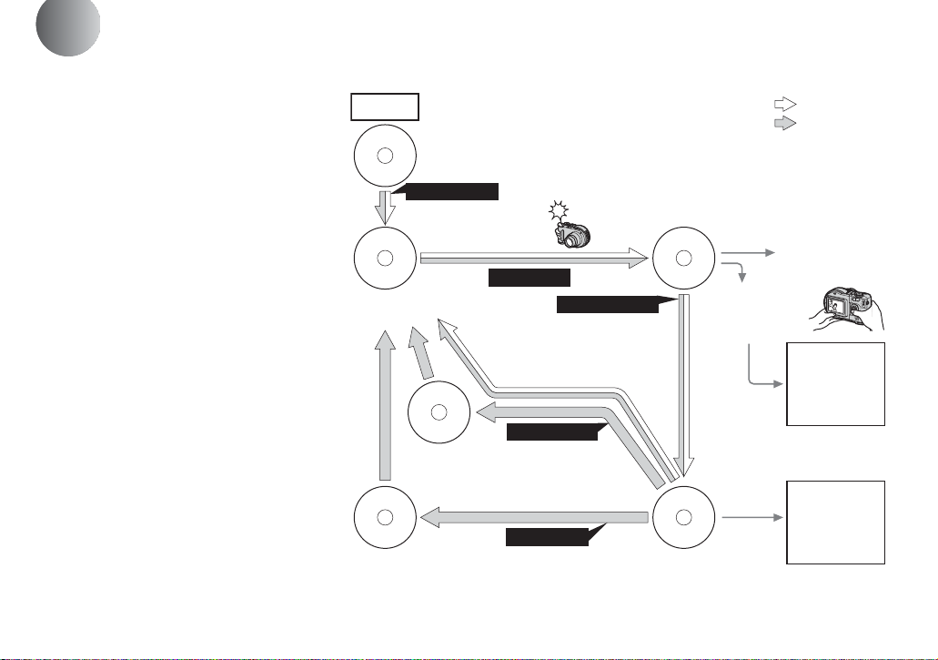
Flow chart for disc operations
Start
A new disc
Initialize
(page 21)
Preparation for recording
on a disc.
Record
Disc preparation for
recording is complete.
The disc status is
pre-finalization.
Blank di sc
Unfinalize
[About 1 min]
(page 46)
About 13 MB disc space
is restored.
Format
[About 7 min]
(page 42)
The disc space is fully
available.
Finalize
[About 1 min]
(page 44)
Preparation for viewing
recorded images on a
computer.
Recording is complete.
View on a computer
(page48)
Disc preparation for
viewing recorded images
through a disc drive is
complete.
: CD-R
: CD-RW
[ ] : Required time
View on the camera
(page 35)
View through
the USB cable
(pages 51, 61)
View through a
disc drive
(pages 48, 61)
10
Page 11
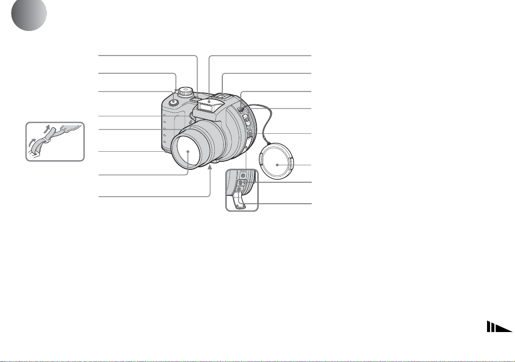
Identifying the parts
1
See the pages in parentheses for details of operati on .
2
3
4
5
6
Attaching the
shoulder strap
A Microphone
B POWER ON/OFF (CHG) switch
(17)
C Shutter button (25)
D Self-timer lamp (MVC-CD250)
(29)/
Hologram AF (MVC-CD400)/
AF illuminator (MVC-CD250)
emitter (31, 116)
E Self-timer lamp (MVC-CD400)
(29)
F Battery cover (13)
G Lens
7
8
9
0
qa
qs
qd
qf
qg
qh
H Tripod receptacle (bottom
surface)
I Flash emitter (29)
J Hot shoe (MVC-CD400)/
Accessory shoe (MVC-CD250)
(84, 117)
K Hook for lens cap/shoulder strap
L Disc cover OPEN lever (20)
M ACC (Accessory) jack
N Lens cap (supplied)
O USB jack (56)
P A/V OUT (MONO) jack (37)
• Do not touch the microphone whi le
recording.
• Use a tripod with a screw length of less
than 5.5 mm (7/32 inch). You will be
unable to firmly secu re t h e c am era to
tripods having longer screws, and may
damage the camera.
• Use ACC jack to con nect an external
flash or other equipment.
• Audio output is monaural.
11
Page 12
1
2
3
4
5
6
7
8
9
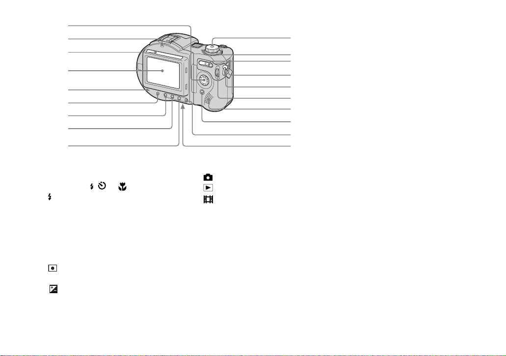
A Control butt on
(Menu on) (v/V/b/B/z)
(Menu off) ( / /7/) (27, 28, 29)
B /CHG (charge) lamp (14)
C Photocell window for LCD
screen
D LCD screen
E ACCESS lamp (20)
F DISPLAY/LCD BACK LIGHT ON/
OFF button (26)
G (Metering mode) button* (72)
H FOCUS button* (66, 69)
I (Exposure) butt on* (70)
12
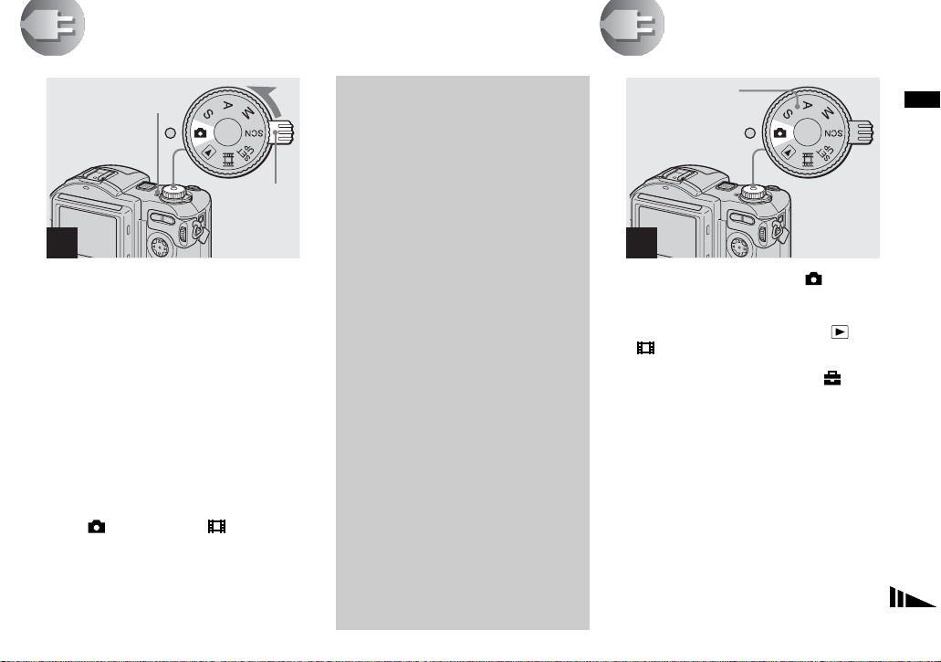
J Mode dial (17)
: To shoot still images
: To view or edit images
: To shoot movies, Clip
Motion images or Multi
Burst mode images
SET UP: To set the SET UP items
SCN: To shoot in the SCENE
SELECTION mode
M: To s hoot in the manual
exposure mode*
A: To shoot in the aperture
priority mode*
S: To shoot in the shutter speed
priority mode*
K POWER la mp (17)
0
qa
qs
qd
qf
qg
qh
qj
qk
ql
L Zoom button (for shooting) (27)/
Index button ( for viewing) (36)
M DC IN jack (13, 16)
N Hook for shoulder strap
O Jog dial* (63)
P Speaker
Q MENU button (22)
R AE LOCK button* (74)
S RESET button (bottom surface)
(98)
• The LCD screen automatically becomes
brighter when this is exposed to sunli ght .
* not available on the MVC-CD250
Page 13
Getting started
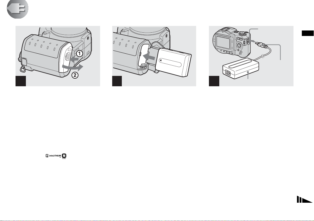
Charging the battery pack
DC IN jack cover
Getting started
DC connecting
cable
1
, Open the battery co ver .
Slide the co ve r i n t he di re ctio n o f th e ar ro w
1. The battery cover open s in the dire ction
the arrow 2.
Be sure to turn off your camera
when charging the battery pack.
• “InfoLITHIUM” is a lithium ion battery pack
which can exchange information such as
battery consumption with compatible video
equipment. “InfoLITHIUM” M series battery
packs have the mark.
• Your camera operates only with the
“InfoLITHIUM” NP-FM50 battery pack (M
series) (supplied) (page 120).
2 3
, Install the battery pack, then
close the battery cover .
Insert the battery pack with the v mark
facing toward the battery compartment as
illustrated.
Make sure the battery pack is firmly
inserted all the way, then close the cover so
that it click s .
• The battery pack is easily inserted by pushing
the battery eject lever at the front of the battery
compartment to the outside.
AC power adaptor (supplied)
, Open the DC IN jack cover and
connect the DC connecting
cable to the DC IN jack of your
camera.
Connect th e cable with the v mark facing
up.
• Do not short the DC plug of the AC power
adaptor with a metallic object, as this may
cause malfunction.
• Do not short the DC plug on the AC power
adaptor with a piece of metal, and do not use
the DC plug if it is dirty. Use a dry cotton swab
to remove any dirt on the DC plug. Using a
dirty plug or shorting the plug can result in
improper charging.
13
Page 14
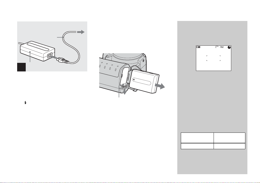
2 To wall outlet
(wall socket)
Power cord
(mains lead)
1
AC power adaptor
(supplied)
4
, Connect th e power cord ( mains
lead) to the AC power adaptor
and then to a wall outlet (wall
socket).
The /CHG lamp (orange) lights up when
charging begins, and goes off when
charging is completed. After charging the
battery pack, disconne ct the AC power
adaptor from the DC IN jack of your
camera.
• We recommend charging the batt ery pack in an
ambient temperature of between 10°C to 30°C
(50°F to 86°F).
• Charging is complete in approximately 150
minutes. The charge lamp may remain lit
longer than 150 minutes, but this is not a
malfunction.
• If sufficient battery remaining time is indicated
but the power runs out soon, fully charge the
battery pack so that the correct battery
remaining time appears.
To remove the battery pack
Battery eject lever
Open the battery cover. Slide the ba ttery
eject lever in the direction of the arrow, and
remove the battery pack.
• Be careful not to drop the battery pack when
removing it.
Battery remaining indicator
The battery remaining indicator on the LCD
shows the remaining shooting or viewing
time.
60min
• When charging, the battery remaining
indicator shows the time remaining in terms
of performing continuous shooting (with all
indicators on).
• The displayed time remaining may not be
correct under certain circumstances or
conditions.
640
4
Charging time
Approximate time to charge a completely
discharged battery pack using the AC-L10A/
L10B AC power adaptor at a temperature of
25°C (77°F).
Battery pack Full charge
NP-FM50 (supplied) Approx. 150
(min.)
14
Page 15
NP-FM50 battery pack
When you shoot images in an extremely cold
location, the operating time becomes short. When
using the camera in an extremely cold location,
place the battery pack in your pocket or other
place to keep it warm, then insert the battery pa ck
into the camera just before shooting. When using
a pocket heater, take care not to let the heater
directly contact the battery.
Battery life and number of
images that can be recorded/
viewed
The tables show the approximate battery life and
the number of images that can be recorded/
viewed with a fully charged battery pack at a
temperature of 25°C (77°F), standard image
quality, (no flash) and in NORMAL
recording mode.
But the remaining indicator will decrease in the
following situations:
– The surrounding temperature is low
– The camera has been turned ON and OFF
many times
– The LCD backlight is set to [BRIGHT]
– The battery power is low
The battery capacity decreases as you use it
more and more and as time passes.
Shooting still images*
MVC-CD400
Image size
2272×1704 Approx. 110 Approx. 1400
640×480 Approx. 110 Approx. 1800
* Shooting at about 4-second intervals
NP-FM50 (supplied)
Battery life
(min.)
No. of
images
MVC-CD250
Image size
1600×1200 Approx. 120 Approx. 2300
640×480 Approx. 120 Approx. 2400
* Shooting at about 3-second intervals
NP-FM50 (supplied)
Battery life
(min.)
No. of
images
Viewing still images**
MVC-CD400
NP-FM50 (supplied)
Image size
2272×1704 Approx. 170 Approx. 1100
640×480 Approx. 170 Approx. 1300
Battery life
(min.)
No. of
images
MVC-CD250
NP-FM50 (supplied)
Image size
1600×1200 Approx. 180 Approx. 120 0
640×480 Approx. 180 Approx. 140 0
** Viewing single images in order at about 5-
second intervals with all indicators on
Battery life
(min.)
No. of
images
Shooting movies
MVC-CD400
NP-FM50 (supplied)
Battery life (min.)
Continuous
recording
Approx. 150
MVC-CD250
NP-FM50 (supplied)
Battery life (min.)
Continuous
recording
• The battery life and number of images will be
decreased when using the camera at low
temperatures, using the flash, turning the
power on/off repeatedly, or using the zoom.
Approx. 170
Getting started
15
Page 16
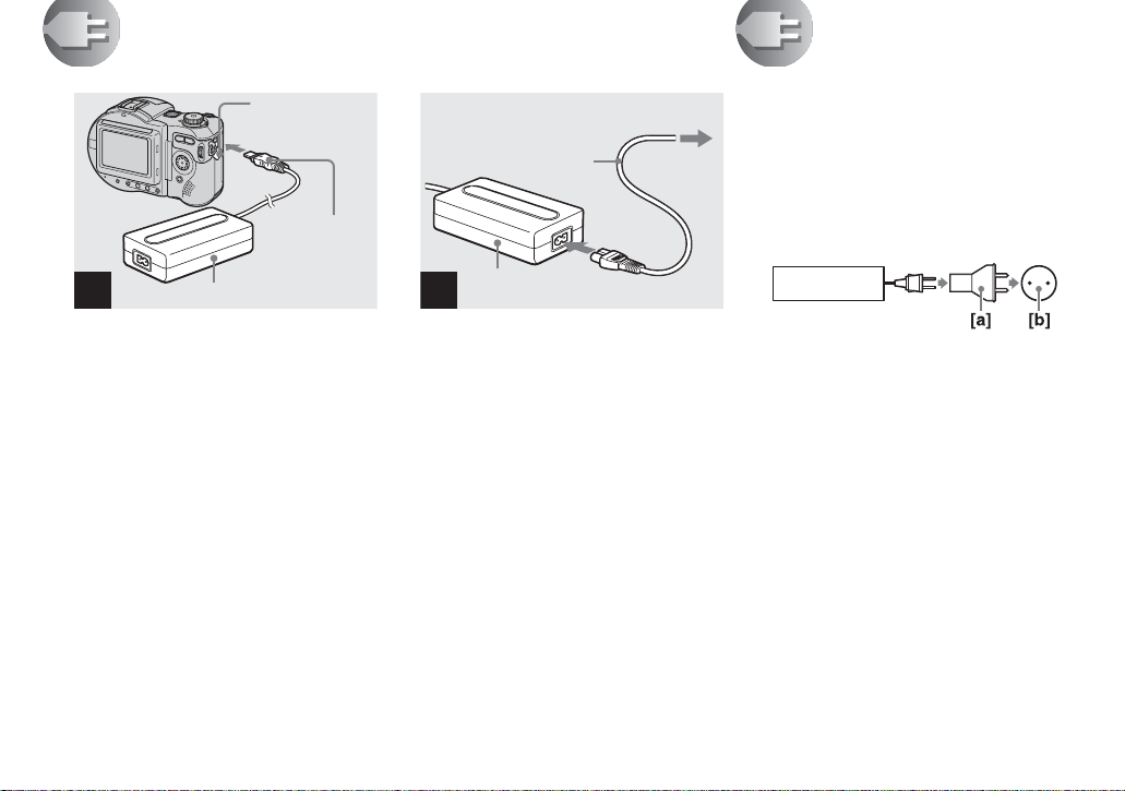
Using an external power source
AC power adaptor (supplied)
1
DC IN jack cover
DC connecting
cable
2
2 To wall outlet (wall socket)
Power cord
(mains lead)
AC power adaptor
(supplied)
1
Using your camera abroad
Power sources
You can use your cam era i n any coun t ry or
area with the supplied battery ch arger
within 100 V to 240 V AC, 50/60 Hz. Use a
commercially available AC plug adaptor
[a], if necessary, depending on the design of
the wall outlet (wall socket) [b].
AC-L10A/L10B
, Open the DC IN jack cover and
connect the DC connecting
cable to the DC IN jack of your
camera.
Connect th e cable with the v mark facing
up.
• Connect the AC power adaptor to an easily
accessible wall outlet (wall socket) close by. If
some trouble occurs while using the adaptor,
immediately shut off the power by
disconnecting the plug from the wall outlet
(wall socket).
• Remove the battery pack when using an
external power source.
16
, Connect the power cord (mains
lead) to the AC power adaptor
and then to a wall outlet (wall
socket).
• When you have finished using the AC power
adaptor, disconnect it from the DC IN jack of
the camera.
• To use po wer from an automobile, use the Sony
DC adaptor/charger (not supplied).
• If you insert or remove the DC plug while you
are using the battery, the power may shut off.
• Do not use an electronic transformer (travel
converter), as this may cause a malfunction.
Page 17
Turning on/off your camera
POWER lamp
POWER
switch
1
, Slide the POWER switch in the
direction of the arrow.
The POWER lamp (g reen) li ghts u p and th e
power is on. When you turn on your camera
for the first time, the CLOCK SET screen
appears (page 17).
Turning off the power
Slide the POWER switch in the direction of
the arrow again. The POW ER lamp goes
out, and the cam era turns off.
• If you turn on the power when the mode dial is
set to ,
portion moves (MVC-CD400 only). Do not
touch the lens portion while it is operating.
S, A, M, SCN or , the lens
Auto power-off function
If you do not operate the camera for
about three minutes during shooting or
viewing or when performing SET UP,
the camera turns off automatically to
prevent wearing down the battery. The
auto power-off function only operates
when the cam era is operat ing using a
battery pack. The auto power-off
function also will not operate in the
following circumstances.
• When viewing movies
• When a connector is plugged into the
USB jack or the A/V OUT jack.
When playing back a Slide Show
(page 87), the power automatically
turns off after about 20 minutes
regardless of the power source (battery
pack or AC power adaptor).
Setting the date and time
Mode dial
1
, Set the mode dial to .
• You can also carry out this operation when the
mode dial is set to S*, A*, M*, SCN, , or
.
• To change the date and time, set the mode dial
to SET UP, select [CLOCK SET] in
[SETUP 1] (page 117), and perform the
procedure from step 3.
* MVC-CD400 only
Getting started
17
Page 18

POWER switch
2
CLOCK SET
2002
1
/:
/
12 00
1
OK
Y/M/D
M/D/Y
D/M/Y
AM
CANCEL
12 00
Y/M/D
M/D/Y
D/M/Y
AM
CANCEL
12 00
Y/M/D
M/D/Y
D/M/Y
AM
CANCEL
OK
CLOCK SET
OK
2002
1
/:
/
1
OK
4
CLOCK SET
OK
2002
1
/:
/
1
OK
3
, Slide the POWER switch in the
direction of the arrow to turn
on the power.
The POWER lamp (g reen) li ghts u p and the
CLOCK SET screen appears on the LCD screen.
18
, Select the desired date display
format with v/V on the control
button, then press z.
Select from [Y/M/D] (year/ month/day),
[M/D/Y] (month/day/yea r) or [D/ M / Y]
(day/month/year).
• If the rechargeable button battery, which
provides the power for saving the time data, is
ever fully discharged (page119), the CLOCK
SET screen will appear again. When this
happens, reset the date and time, by starting
from step 3 above.
, Select the year, month, day,
hour or minute item you want
to set with b/B on the control
button.
The item to be set is indicated with v/V.
Page 19

CLOCK SET
2002
1
/:
/
12 00
7
OK
Y/M/D
M/D/Y
D/M/Y
AM
CANCEL
Getting started
10 30
Y/M/D
M/D/Y
D/M/Y
PM
CANCEL
OK
CLOCK SET
2002
4
/:
/
OK
7
OK
5
, Set the numeric value with v/V
on the control button, then
press z to enter it.
After ente r ing the number , v/V moves to
the next item. Repeat this step until all of
the items are set.
• If you selected [D/M/Y] in step 3, set the time
on a 24-hour cycle.
6
, Select [OK] with B on the
control button, then press z.
The date and time are en tered a nd the cloc k
starts to keep time.
• To cancel the date and time setting, select
[CANCEL] with v/V/b/B on the control
button, then press z.
19
Page 20
Inserting a disc
Shooting still images
Disc cover
OPEN lever
Lock tab
Pickup lens
Disc
1
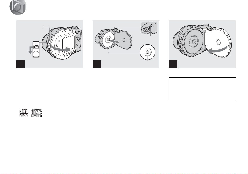
, Open the disc cover.
While sliding the lock tab to the left, slide
down the disc cover OPEN lever, and open
the disc cover.
• You can use only 8 cm CD-R/CD-RW
discs that have these marks.
20
2
Push here
, Place a disc in the disc tray.
Place the disc wit h the printed side up, and
push down on the center of the disc until it
clicks.
• Do not push with too force on the disc.
• Do not touch the pickup lens.
3
, Close the disc cover.
Removing the disc
While sliding the lock tab to the left, slide down
the disc cover OPEN lever, and open the disc
cover. Check t o make sure that t he dis c has
completely stopped rotating, then remove the disc.
• When the ACCESS lamp is lit up, it
means that image data is being read or
written. Never open the disc cover or
turn off the power at this time, as the
image data may be da mage d or th e d is c
may become unusable.
• While the camera is writing data on a disc, the
disc cover OPEN lever is locked.
• After you change the disc, “REPAIRING
DATA” may appear on the LCD screen and it
may take about 10 minutes to prepare the disc
for recording depending on the disc condition.
Page 21
Initializing a disc
What is initialization?
Initialization is required to record images
on a disc.
When you perform fina li za ti on (page 44)
using your camera to view images through
a disc drive, initializa tion is also
automatically pe rformed, and you can
continue to reco rd images. Im ages record ed
before finalization remain on the disc.
Mode dial
1
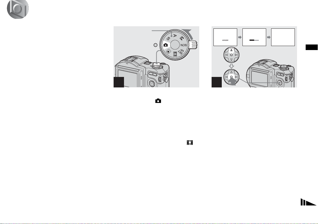
, Insert a new disc and set the
mode dial to , then turn on
the power.
“INITIALIZE PLACE ON LEVEL
SURFACE” appears on the LCD screen.
• You can also carry out this operation when the
mode dial is set to S* , A*, M*, SCN or .
* MVC-CD400 only
INITIALIZE
AVOID ANY VIBRATION
READY TO INITIALIZE
INITIALIZE
AVOID ANY VIBRATION
INITIALIZE IN PROGRESS
INITIALIZE
INITIALIZE COMPLETE
2
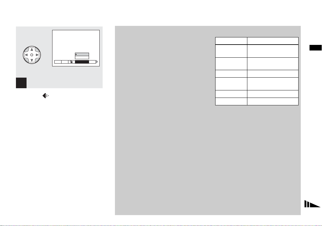
, Select [OK] with v on the
control button, then press z.
Initialization starts. Do not shake or strike
the camera during initialization.
To cancel initialization
Select [CANCEL] with
button, then press
V on the control
z.
Shooting still images
21
Page 22

Initializing after canceling the
initialization
Open and close th e di sc cover, or set the
mode dial to , S*, A*, M*,
, select [EXEC] with
button, th en press
* MVC-CD400 only
z.
SCN, or
v on the control
Setting the still image size and image quality
2272×1704
ISO
2272 (3 : 2)
1600×1200
1280×960
640 × 480
IMAGESIZE
1600×1200
1600 (3 : 2)
1280×960
640 × 480
IMAGE SIZE
•
Y ou can also perform initialization using
[DISC TOOL] in the SET UP settings
(page 116).
22
1
MENU
, Set the mode dial to , and
turn on the power, then press
MENU.
The menu appears.
• You can also carry out this operation when the
mode dial is set to S*, A*, M* or SCN.
• (EV), 9 (FOCUS) and (SPOT
METER) are displayed on the MVC-CD250
menu (page 62).
* MVC-CD400 only
MVC-CD400 MVC-CD250
2
, Select (IMAGE SIZE) with b/
B on the control button, then
select the desired image si ze
with v/V.
The image size is set.
Page 23
FINE
FINE
STANDARD
WB
ISO
P.QUALITY
MODE
3
, Select (P.QUALITY) with b/
B on the control button, then
select the desired image
quality with v/V.
The image quality is set.
When the setting is complete, press MENU
so that the menu disappears from the LCD
screen.
• You can select the image quality from either
[FINE] or [STANDARD].
• The image size and quality values selected here
are maintained even when the power is turned
off.
Image size and quality
You can choose the image size ( number of
pixels) and the image quality
(compression ratio) according to the kind
of images you want to shoot. Larger
image sizes and higher image quali ty
result in better images, but also a larger
data size, which means fewer imag es that
you can record on a disc.
Choose an image size and quali ty
appropriate for the kind of images you
want to shoot.
You can resize the images later (Resize
function , see page 91).
You can choose from th e following table.
Image size Usage
2272×1704
Very fine prints
(MVC-CD400)
2272 (3:2)
Printing in 3:2 ratio
1)
(MVC-CD400)
1600×1200 Printing in A4 format
1600 (3:2)
Printing in 3:2 ratio
1)
(MVC-CD250)
1280×960 Printing in postcard size
640×480 Attaching to e-ma il
1)
The image is recorded in the horizontal to
vertical ratio of 3:2 to fit the printing paper
size.
Shooting still images
23
Page 24
Number of images2) that can be
saved on a disc
(Units: images)
Quality
Image size
2272×1704
(MVC-CD400)
2272 (3:2)
(MVC-CD400)
1600×1200 131 235
1600 (3:2)
(MVC-CD250)
1280×960 195 347
640×480 658 1291
2)
When [MODE] (REC MODE) is set to
[NORMAL].
For the number of images that can be saved in
other modes, see page 110.
• Image size is the size when viewing the
images on a personal computer. Images
viewed on the LCD screen of the camera all
appear the same size.
• The actual number of images may differ
depending on the shooting conditions.
• The image size value (e.g., 2272×1704)
indicates the number of pixels.
FINE STANDARD
66 119
66 119
131 235
Basic still image shooting (using auto adjustment mode)
Mode dial
1
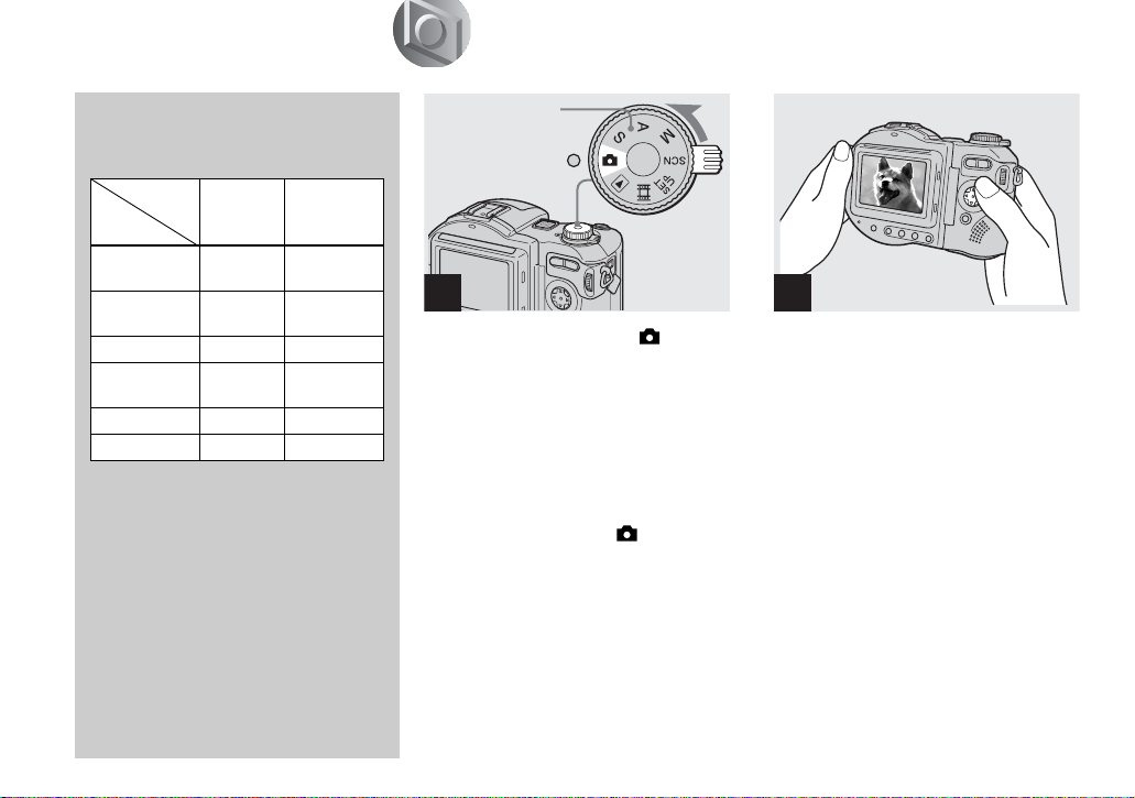
, Set the mode dial to , and
turn on the power.
Remove the lens cap.
• Still images are recorded in JPEG format.
• When you turn on the power or use the zoom
(page 27), the lens portion moves
(MVC-CD400 only). Do not touch the lens
portion while it is operating.
• When the mode dial is set to , the exposure
and focus are adjusted automatically.
2
, Hold the camera steadily wit h
both hands and position the
subject in the center of the
focus frame.
The lens portion moves when you turn on
the power (MVC-CD400 only)
• You can choose either Multipoint AF or Focus
range select mode (MVC-CD400), or Multipoint AF mode or Center AF (MVC-CD250) as
the AF mode (page 66).
24
Page 25

60min
3
640
Flashes green
t Lights up
4
0EV
F5.6
50
4
60min
640
• While the image is being recorded on the disc,
the ACCESS lamp lights up. Do not shake or
strike the camera while this lamp is lit. Also do
not turn off the power, remove the battery pack
or disc, or open the disc cover at this time, as
the image data may be damaged or the disc may
become unusable.
• Do not cover the lens or flash with your fingers.
Shooting still images
, Press and hold the shutter
button halfway down.
The beep sounds but the ima ge is not yet
recorded. When the AE/AF lock indicator
changes from flashing to light ed up, the
camera is ready for sho o t ing.
The flash automatically pops up and strobes
when the surroundings are dark.
• If you release the shutter button, the recording
will be canceled.
• The minimum focal distance to the subject is
50 cm (19 3/4 inches). To shoot even closer
subjects, use macro recording mode (page 28).
• The frame appearing on the LCD screen shows
the focus adjustment range. (For more details
on the AF range finder, see page 68.)
, Press the shutter button fully
down.
The shutter sounds. “RECORDING ”
appears on the LCD scr een, and the
image will b e recorded on the di sc. When
“RECORDING” disappears, you can
shoot the next image
• When operating the camera using a battery
pack, if you do not operate the camera for about
three minutes during recording or playback, the
camera turns off automatically to prevent
wearing down the battery (page 17).
• When [CONFIRM B. WRITE] in the SET UP
settings is set to [ON], you can select whether
to actually record the image on a disc
(page 83).
.
25
Page 26
Auto Focus
When you try to sh oo t a s u bject that is
difficult to focus on, the AE/AF lock
indicator changes to flashing slowly.
The Auto Focus function may have
difficulty working under the following
conditions. In such cases, release the
shutter button, then recompose the shot
and focus again.
• The subject is distant from the
camera and dark.
• The contrast between the subject and
its background is poor.
• The subject is seen through glass,
such as a window.
• A fast-moving subject.
• The subject reflects or has a lustrous
finish, such as a mirror or a luminous
body.
• A flashing subject.
LCD screen indicators during shooting
DISPLAY/LCD BACK LIGHT ON/OFF
This is useful for extending the battery life
and for shooting under conditions where the
image is difficult to check using the LCD
screen.
Each time you press DISPLAY/LCD
BACK LIGH T ON/OFF, the display
changes in the following order.
Indicators off (Only warning messages
and manual adjustment items which are
set using the jog dial are on. (MVC-CD400
only))
r
LCD backlight off
r
All indicators on
60min
• For a detailed description of the indicators, see
page 124.
• Indicators on the LCD screen are not recorded.
640
4
26
Page 27
Checking the last image you shot (Quick Review)
60min
640
10:30
8/8
PM
REVIEW
2002 7 4100-0029
, Press b (7) on the contro l
button.
To return to the normal shooting mode,
press lightly on the shutter button or press b
(7) again.
To delete the image displayed on the
LCD screen
1 Press MENU to display the menu.
2 Select [DELETE] with B on the control
button, then press z.
3 Select [OK] with v on the control
button, then press z.
The image is d eleted.
Using the zoom feature
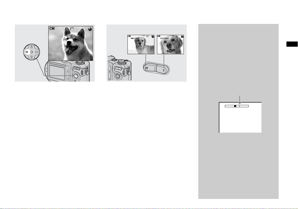
W (wide-angle) T (telephoto )
640
W
T
60min 60min
4
640
4
T
W
, Press the zoom button to
choose the desired image size
for shooting.
Minimum focal distance to the
subject
When the zoom is set to the W side:
About 50 c m (19 3/4 inches) (M VC-CD400)
About 50 c m (19 3/4 inches) (M VC-CD250)
When the zoom is set to the T side:
About 50 c m (19 3/4 inches) (M VC-CD400)
About 80 c m (31 1/2 inches) (M VC-CD250)
• The lens portion moves during zoom operation
(MVC-CD400 only). Do not touch the lens
portion while it is operating.
• Zoom does not work for movies (page 94)
(MVC-CD400 only).
Digital zoom
When zoom exceeds 3×, the image is
enlarged by digital processi ng. The
maximum digital zoom magnification
is 6×. Digital zooming deteriorates the
image quality, so when digital zoom is
not necessary, set [DIGITAL ZOOM ]
to [OFF] in th e S ET UP settings
(page 116).
The T side of the bar shows
the digital zoom zone.
W
• During digital zoom, the AF frame does
not appear on the LCD screen.
• Digital zoom does not work for movies.
T
Shooting still images
27
Page 28
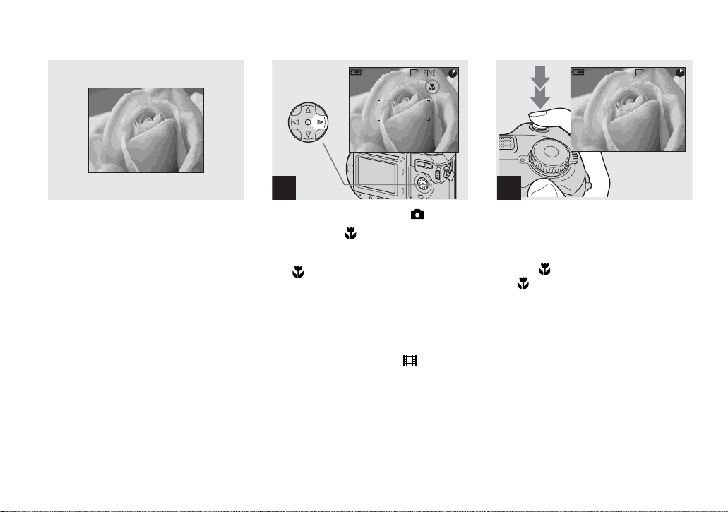
Shooting close-ups (Macro)
The macro recording mode is used when
zooming up a small subject, such as flowers
or insects. You can shoot close-ups of
subjects up to the distances specified below.
When the zoom is set all the way to
the W side:
Approx. 4 cm (1 5/8 inches) from the lens
surface (MVC-CD400)
Approx. 3 cm (1 3/16 inches) from the lens
surface (MVC-CD250)
When the zoom is set all the way to
the T side:
Approx. 20 cm (7 7/8 inches) from the lens
surface (MVC-CD400)
Approx. 80 cm (31 1/2 inches) from the lens
surface (MVC-CD250)
60min
640
4
1
, Set the mode dial to , and
press B ( ) on the control
button.
The (macro) indicator appe ars on the
LCD screen.
• If the menu is currently displayed, press MENU
first so that the menu disappears.
• You can also carry out this operation when the
mode dial is set to S*, A*, M*, SCN (other than
landscape mode) (page 33), or .
* MVC-CD400 only
60min
640
2
, Center th e subject in t he frame,
and shoot the image.
To return to normal recording mode
Press B ( ) on the control button again.
The indicator disappears.
28
Page 29
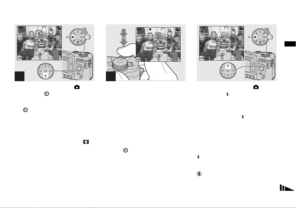
Using the self-timer
Selecting a flash mode
60min
640
4
1
, Turn the mode dial to , and
press V ( ) on the control
button.
The (self-timer) indi cator app ears on t he
LCD screen.
• If the menu is currently displayed, press MENU
first so that the menu disappears.
• You can also carry out this operation when the
mode dial is set to S*, A*, M*, SCN, or .
* MVC-CD400 only
60min
640
3
0EV
F5.6
50
2
, Center the subject in the frame,
and press the shutter button
fully down.
The self-timer l amp (p age 11) flashes and a
beep sounds after you press the shutter
button until the shutter button is released
(approximately 10 seconds).
To cancel the self-timer in the middle
of the operation
Press V ( ) on the control button agai n.
• If you press the shutter button while standing in
front of the camera, the focus and the exposure
may not be correctly set.
60min
640
4
, Set the mode dial to , and
press v ( ) on the control
button repeatedly to sele ct a
flash mode.
Each time you press v ( ), the indicator
changes as follows.
No indicator (Auto): The flash
automatically pops up and strobes when the
surroundings are dark (defa ult).
r
(Forced flash): The flash strobes
regardless of the surrounding brightness.
r
(No flash): The flash does not strobe.
Shooting still images
29
Page 30
• If the menu is currently displayed, press MENU
first so that the menu disappears.
• Y ou can cha nge the brightness of the flash with
[FLASH LEVEL] in the menu settings
(page 112).
• When using the Auto or
mode, you may notice some noise in the
image when you look at the LCD screen in a
dark place, but t his will hav e no ef fect on the
shot image.
• While charging the flash, the /CHG la mp
flashes. After the ch arging is comple te, the
lamp goes out.
• When you press the shutter button halfway
down while the flash is strobing, the /CHG
lamp turns on.
• Attaching a conversion lens (not supplied) may
block the light from the built-in flash or cause
the lens shadow to appear.
• You cannot use an external flash that supports
hot shoe (not supplied) and the built-in flash at
the same time.
• When using a commercially available external
flash, set [HOT SHOE] to [ON] in the SET UP
settings (MVC-CD400 only).
• Two types of external flash can be used: the
optional HVL-F1000 flash and commercially
available flashes that support hot shoe
(page 84).
• You cannot use the external flash HVL-F1000
(optional) and the built-in flash at the same
time.
(Forced flash)
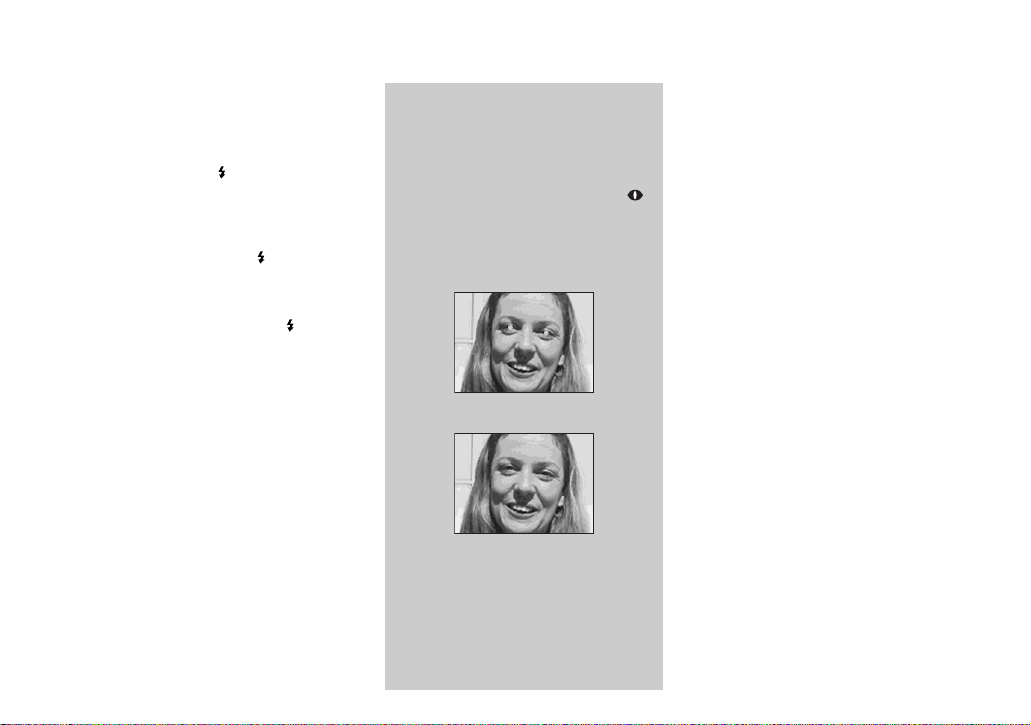
To reduce the red-eye
phenomenon when
shooting live subjects
Set [RED EYE REDUCTION] to [ON]
in the SET UP settings (page 116).
indicator appears on the LCD screen,
and the flash pre-strobes before
shooting to reduce the red-e ye
phenomenon.
m
• Red-eye reduction may not produce the
desired effects depending on individual
differences, the distance to the subject, if
the subject does not see the pre-strobe, or
other conditions.
30
Page 31

Recording images with the
1)
ON
60min
ON
/AF illuminator
1)
or AF illuminator2)
640
6
hologram AF
The hologram AF1)/AF illuminator2) is fill
light to focus more easily on a subjec t in
dark surroundings. Set [HOLOGRAM
1)
or [AF ILLUMINATOR]2)
AF]
(page 116) to [AUTO] in the SET UP
settings. appear s on the LCD scr ee n
and the hologram AF
emits light when the shutter butt on is
pressed halfway until the focus is locked.
• If hologram AF1) or AF illuminator2) light
does not reach the subject sufficiently or the
subject has no contrast, focus will not be
achieved. (An approximate distance of 0.5 to
4.0 m (19 3/4 inches to 13 feet 1 3/8 inches)
for the MVC-CD400 and 0.3 to 2.3 m (11 7/8
inches to 7 feet 6 1/2 inches) for the
MVC-CD250 is recommended.)
• Focus is achiev ed as long as hologram AF
2)
AF illuminator
even if the light is slightly out of the middle
position of the subject.
• The hologram AF
2)
light reaches the subject,
1)
or AF illuminator2) will
not emit light when adjusting the focus
manually.
• The hologram AF will not emit light when
[CONVERSION LENS] is set to [ON] in the
SET UP settings (page 117). (MVC-CD400
only)
• If the hologram AF
1)
emitter is dirty, the
hologram AF light may be dimmed and focus
may not be achieved. In this case, wipe the
hologram AF emitter with a dry cloth.
• No safety problems will be caused by directly
looking into the hologram AF
illuminator
2)
emitter at a close range.
However, it is not recommended to do so,
because you may experience such effects like
several minutes of residual image and
dazzling, like that encountered after looking
into a flashlight.
• Do not block the hologram AF
illuminator emitter during recording.
1)
MVC-CD400 only
2)
MVC-CD250 only
1)
or AF
1)
or AF
1)
or
About Hologram AF
(MVC-CD400 only)
“Hologram AF (A uto-Focus)” is a new
AF optical system that applies laser
holograms to enable you to shoot still
images in dark places. The Hologram AF
system uses gentler radiation tha n
conventional high-brig ht ness L EDs or
lamps, thus satisfying Laser Class 1*
specifications and maintaini ng higher
safety for human eyes.
* Hologram AF satisfies Class 1 (time base
30,000 seconds), specified in all of JIS
(Japan), IEC (EU), and FDA (US) industry
standards. Complying with these standards
identifies the laser product to be safe, under a
condition that a human looks at the laser light
either directly or even through a lens for
30,000 seconds.
2)
Shooting still images
31
Page 32

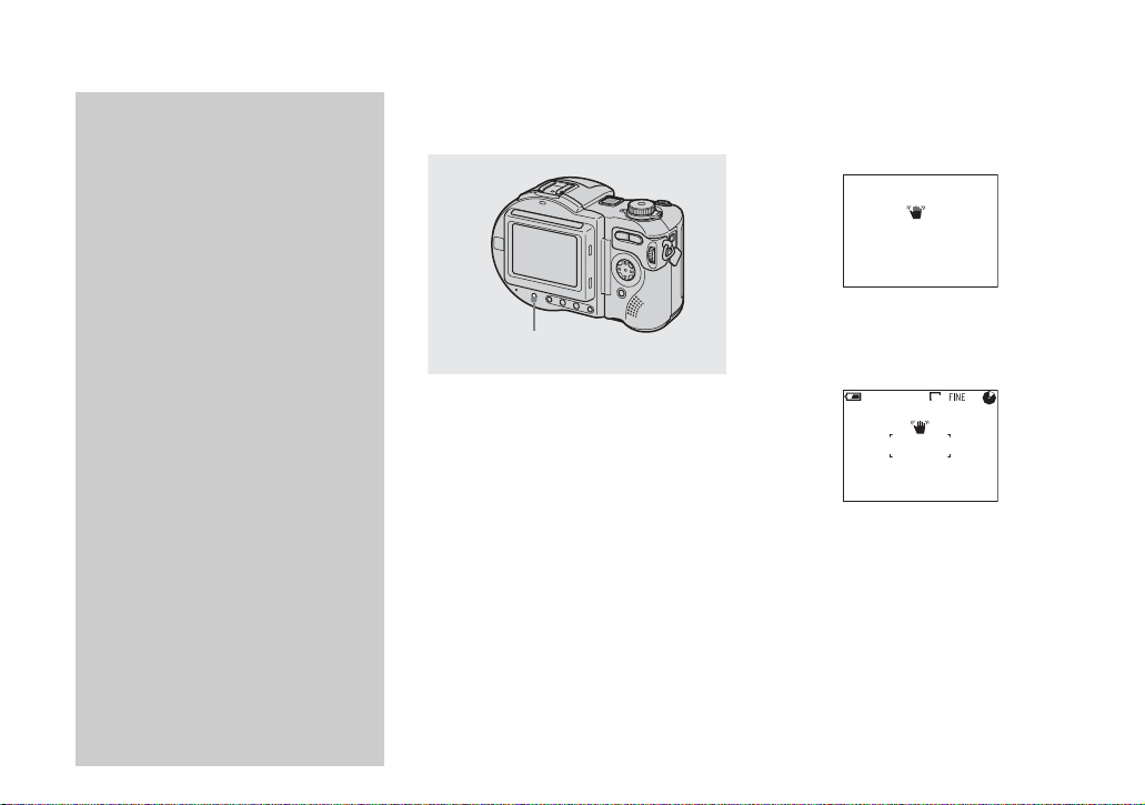
Inserting the date and time on a still image
DISC TOOL
FINALIZE :
FORMAT :
INITIALIZE :
UNFINALIZE :
SELECT
1 2
, Set the mode dial to SET UP.
The SET UP screen appears.
• When images are shot with the date and time
superimposed, the date and time cannot be
removed later.
• The date and time do not appear on the LCD
screen during shooting, instead, “ ” appears
in the upper left corner of the LCD screen. The
actual date and time appear during playback
only.
CAMERA
MOVING IMAGE :
DATE/TIME :
DIGITAL ZOOM :
BRACKET STEP :
RED EYE REDUCTION :
HOLOGRAM AF :
OK
DAY&TIME
DATE
OFF
, Select [CAMERA] with v/V
on the control button, then
press B.
Select [DATE/TIME] with v/V,
then press B.
• If you select [DATE], the date is superimposed
onto the image in the order selected with
“Setting the date and time” (page 17).
• On MVC-CD250, the [HOLOGRAM AF] item
is displayed as [AF ILLUMINATOR] and the
[BRACKET STEP] (page 116) item is not
displayed in
[CAMERA].
CAMERA
MOVING IMAGE :
DATE/TIME :
DIGITAL ZOOM :
BRACKET STEP :
RED EYE REDUCTION :
HOLOGRAM AF :
PAGE SELECT
MPEG MOVIE
DATE
ON
±0.7EV
OFF
AUTO
3
, Select the date and time setting
with v/V on the control button,
then press z.
DAY & TIME: Superimposes the date,
hour, and minute onto the image.
DATE: Superimposes the year, month and
day onto the image.
OFF: Does not superimpose the da t e and
time onto the image.
After the setting has been complet ed, set the
mode dial to , and shoot the image.
• You can also shoot images with the mode dial
set to S*, A*, M* or SCN.
• This setting is maintained even when the power
is turned off.
* MVC-CD400 only
32
Page 33

Shooting according to scene conditions (Scene Selection)
Twilight mode Twilight portrait mode Landscape mode Portrait mode
Shooting still images
When shooting night scenes, shoot ing
people at night, or shooting landscapes, use
the modes listed below to improve the
quality of your images.
Twilight mode
Allows you to shoot night scenes w i tho ut
losing the dark atmosphere of t he
surroundings. The shutter spe ed bec om e s
slower, so we recommend that you use a
tripod to prevent shaking .
• The flash cannot be used in this mode.
Twilight portrait mode
Suitable for shooting portraits in dark
places. The shutter speed beco mes slow e r,
so we recommend that you use a tripod to
prevent sha k ing.
• Allows you to shoot sharp images of people in
dark places without losing the dark atmosphere
of the surroundings.
• The flash strobes regardless of the surrounding
brightness.
Landscape mode
Focuses only on a distant subject t o shoot
landscapes, etc.
• You cannot shoot in macro mode.
• The flash does not strobe automatically.
Portrait mode (MVC-CD400
only)
Suitable for shooting portraits.
Backgrounds blur away, and the subject is
sharpened.
If the shutter speed becomes 1/ 2 second
or slower (MVC-CD250) or
1/25 second or slower (MVC-CD400)
in the Twilight or Twilight portrait
mode, “NR” is displayed before the
shutter speed and the NR slow shutter
mode is automatically activated.
NR slow shutter
The NR slow shutter function removes
noise from recorded images to provide
clean, crisp images . Us i ng a tripod is
recommended to prevent shaking.
Press the shutter button fully down.
r
“CAPTURING” is di spl ayed.
The screen turns black.
r
“PROCESSING” is displayed.
r
“RECORDING” is displayed, and the
image is recorde d .
33
Page 34

SCN
WB MODE
SCN
WB MODE
1
MENU
, Set the mode dial to SCN, then
press MENU.
The menu appears.
34
2
, Select [SCN] with b/B on the
control button.
• (EV), 9 (FOCUS) and (SPOT
METER) are displayed on the MVC-CD250
menu (page 62).
3
, Select the desired mode with
v/V on the control button.
The mode is set.
When the setting is co mplete, press MENU
so that the menu disappears from the LCD
screen.
• To cancel Scene Selection, set the mode dial to
a different mode.
• This setting is maintained even when the power
is turned off.
Page 35

Viewing still images
Viewing images on the LCD screen of your camera
Single (single-image)
screen
60min
640
2/28
10:30
2002 7 4100-0002
FILE BACK/NEXT VOLUME
PM
Index (nine-image)
screen
SINGLE DISPLAY
•
Index (triple-image)
screen
APERTURE VALUE :
SHUTTER SPEED :
EXPOSURE VALUE :
ISO
SINGLE DISPLAY
•
F5.6
1/125
0.0
:
100
10:30
2002 7 4100-0002
PM
Viewing single images
60min
640
8/8
10:30
FILE BACK/NEXT
2002 7 4100-0028
VOLUME
PM
1
Viewing still image s
You can view images shot with your camera
almost immediately on the LCD screen.
You can select the following three methods
for viewing images.
Single (single-image) screen
You can view one image at a time,
displayed over the entire scre en .
Index (nine-image) screen
Nine images are displaye d simultaneously
in separate panels on the scree n.
Index (triple-image) screen
Three images are displayed simultaneously
in separate panels on the screen. Various
image inform atio n i tem s are al so d is play ed.
• For a detailed description of the screen
indicators, see page 126.
• For details on the movies, see page 95.
, Set the mode dial to , and
turn on the power.
The last image you sho t appears on the LCD
screen.
35
Page 36

Viewing an index screen (nine-image or triple-image)
60min
640
6/8
FILE BACK/NEXT
APERTURE VALUE :
SHUTTER SPEED :
EXPOSURE VALUE :
ISO
10:30
VOLUME
PM
SINGLE DISPLAY
•
SINGLE DISPLAY
•
2002 7 4100-0026
F5.6
1/125
0.0
:
100
10:30
2002 7 4100-0002
PM
2
, Select the desired still image
with b/B on the control button.
b : To display the preced ing im age
B : To display the next image
36
, Press the zoom W button once.
The display switches to the Index (nineimage) screen.
To display the next (previous) index
screen
Press v/V/
b/B on the control button t o
move the yellow frame up /do w n/ le ft/right.
, Press the zoom W button
again.
The display switches to the Index (tripleimage) screen.
Press v/V on the control button to display
the remaining image information.
To display the next (previous) index
screen
b/B on the control button.
Press
To return to the single-image screen
Press the zoom T button repeatedly, or press
z on the control button.
Page 37

Viewing images on a TV screen
60min
640
6/8
A/V
connecting
cable
(supplied)
1
A/V OUT (Mono) jack
, Connect the A/V connecting
cable to the A/V OUT (Mono)
jack of the camera and the
audio/video input jacks of the
TV.
• If your TV has stereo input jacks, connect the
audio plug (black) of the A/V connecting cable
to the Lch jack.
• Turn off both your camera and the TV before
connecting the camera and the TV with the A/V
connecting cable.
2
TV/Video switch
, Turn on the TV and set the TV/
Video switch to “Video”.
• The name and location of this switch may differ
depending on your TV.
10:30
PM
2002 7 4100-0028
FILE BACK/NEXT VOLUME
3
, Set the mode dial to , and
turn on the camera.
Press b/B on the control button to select the
desired image.
• When using your camera abroad, it may be
necessary to switch the video output signal to
match that of your TV system (page 117).
Viewing still image s
37
Page 38

Viewing images on a TV screen
If you want to view images on a TV
screen, you need a TV with a video input
jack and a video co nn ecting cable.
The color system of the TV must match
that of your di gital s till camer a. Check t he
following lists:
NTSC system
Bahama Islands, Bolivia, Canada, Central
America, Chile, Colomb ia, Ecuador,
Jamaica, Japan, Korea, Mexico, Peru,
Surinam, Taiwan, the Philippines, the
U.S.A., Venezuela, etc.
PAL system
Australia, A us tr ia, Belgium, China,
Czech Republic, Denm ark, Finland,
Germany, Holland, Hong Kong, Italy,
Kuwait, Malaysia, New Zealand,
Norway, Portugal, Singapore, Slov ak
Republic, Spain, Sweden, Switzerland,
Thailand, United Kingdom, etc.
PAL-M system
Brazil
PAL-N system
Argentina, Paraguay, Uruguay
SECAM system
Bulgaria, France, Guiana, Hungary, Iran,
Iraq, Monaco, Poland, Russia, Ukraine,
etc.
38
Page 39

Deleting still images
Deleting images
Deleting images in singe-image mode
60min
640
5/5
10:30
FILE BACK/NEXT
2002 7 4100-0028
VOLUME
PM
1
, Set the mode dial to , and
turn on the camera.
Press b/B on the control
button to select the image you
want to delete.
• When using a CD-R, the disc remaining space
does not increase even if you delete images.
• When using a CD-RW , the disc remaining
space only increases if you delete the last
image you shot while is indicated on the
LCD screen. If you modify an image, or open
and close the disc cover, disappears.
60min
640
5/5
DELETE
PROTECT
OK
2
MENU
PRINT SLIDE
, Press MENU and select
[DELETE] with b/B on the
control button, then press z.
The image has not yet bee n d eleted at th is
point.
• If the disc remaining space is not sufficient, you
may not be able to delete the image.
• If there are file names on the disc with names
having the same last 4 digits as the file name of
the image to be deleted, these files are also
deleted at the same time.
60min
640
5/5
DELETE
OK
OK
CANCEL
3
, Select [OK] with v on the
control button, then press z.
“DISC ACCESS” appears on the LCD
screen. When this message disappears, the
image has been deleted.
To cancel deleting
Select [CANCEL] with V on the control
button, then press z.
Deleting still images
39
Page 40

Deleting images in index (nine-image) mode
PROTECT PRINTDELETE
1
MENU
, While an index (nine-image)
screen (page 36) is displayed,
press MENU and select
[DELETE] with b/B on the
control button, then press z.
40
CANCEL
DELETE
ALLSELECT
2
, Select [SELECT] with b/B on
the control button, then press
z.
To delete all the images in the screen
Select [AL L] with b
button, then press z. Select [OK], then
press z. To cancel deleting, select [EXIT],
then press z.
/B on the control
MENU
SET
•
TO NEXT
3
, Select an image you want to
delete with v/V/b/B on the
control button, then press z.
The (delete) indicator appears on the
selected image. At this poi nt, the ima ge has
not yet been deleted. Repeat this step for all
of the images you want to delete.
• To cancel a selection, press z again so that the
indicator disappears.
Page 41

Deleting images in index (triple-image) mode
EXITDELETE OK
4
, Press MENU and se lect [OK ]
with b/B on the control button,
then press z.
“DISC ACCESS” appears on the LCD
screen. When this message disappears, the
images have been deleted.
To cancel deleting
Select [EXIT] with b on the control button,
then press z.
APERTURE VALUE :
SHUTTER SPEED :
EXPOSURE VALUE :
ISO
SINGLE DISPLAY
•
F5.6
1/125
0.0
:
100
10:30
2002 7 4100-0028
1
, While an index (triple-image)
screen (page 36) is displayed,
set the images you want to
delete to the center with b/B on
the control button.
PRINT
PROTECT
DELETE
10:30
PM
2002 7 4100-0028
OK
•
PM
Deleting still images
2
MENU
, Press MENU and select
[DELETE] with V on the control
button, then press z.
The images have not yet b een deleted at th is
point.
41
Page 42

Formatting a CD-RW
DISC TOOL
FINALIZE :
DELETE
OK
CANCEL
10:30
2002 7 4100-0002
OK
•
PM
FORMAT :
INITIALIZE :
UNFINALIZE :
OK
OK
CANCEL
3
, Select [OK] with v on the
control button, then press z.
“DISC ACCESS” appe ars on the LCD
screen. When this message disappears, the
images have been deleted.
To cancel deleting
Select [CANCEL] with V on the control
button, th en press z.
42
1
, Place the CD-RW you want to
format in the disc tray.
Set the mode dial to SET UP,
and turn on the camera.
• Formatting is performed to delete all the images
on the CD-RW or to use a CD-RW formatted
with other equipment than this camera. When
you format a CD-RW, al l data stored on
the disc will be deleted. Check the
contents of the disc before formatt ing.
The CD-RW is also automatically
initialized after formatti ng.
2
, Select [DISC TOOL] with v/
V on the control button, then
press B. Select [FORMAT] with
v/V, then press B.
• When you format, be sure to use a fully charged
battery pack or the AC power adaptor as the
power source.
• A CD-R cannot be formatted.
Page 43

FORMAT
PLACE ON LEVEL SURFACE
ALL DATA WILL BE ERASED
OK
READY?
O K
CANCEL
FORMAT
AVOID ANY VIBRATION
FORMAT IN PROGRESS
3
, Select [OK] with v/V on the
control button, then press z.
“FORMAT PLACE ON LEVEL
SURFACE” appears on the LCD screen.
To cancel formatting
Select [CANCEL] with V/v on the c ontrol
button, then press z.
• A CD-RW formatted using other equipment
than this camera cannot be used with this
camera. Format the disc again with this camera.
4
Deleting still images
, Select [OK] with v/V, then
press z.
When the message disappears, formatting
has been completed.
• Formatting takes about seven minutes.
• A CD-RW can be formatted about 300 times.
• When you format a CD-RW, protected images
are also deleted.
43
Page 44

Preparation for viewing images using a computer (Finalize)
Copying images to your computer
Finalizing a disc
You must execute finalization before
viewing images recorded with your camera
through a disc drive. Discs that have not
been finalized cannot be read with a disc
drive.
What is finalization?
• Finalization is required to view images
recorded with your camera through a disc
drive.
• You can record new images on a finalized
disc by initializing it again. Initialization
is automatically performed wh en a disc i s
finalized using the camera. You must
execute finalization to view new images
through a disc drive. However, each time
you execute finali zation, the disc
remaining space will decrease by
approximately 13 MB. Ther efore, we
recommend that you execute finalization
for multip le images at a ti me.
• You can finalize a disc later, even if you
remove it fr o m the camera.
• The disc drive must support MultiRead in
order to read discs that have been
finalized.
DISC TOOL
FINALIZE :
FORMAT :
INITIALIZE :
UNFINALIZE :
SELECT
1
, Set the mode dial to SET UP,
and turn on th e power.
The SET UP screen appears on the LCD
screen.
DISC TOOL
FINALIZE :
FORMAT :
INITIALIZE :
UNFINALIZE :
OK
OK
CANCEL
2
, Select [DISC TOOL] with v/
V on the control button, then
press B.
Select [FINALIZE] with v/V,
then press B.
44
Page 45

FINALIZE
RW
RW
PLACE ON LEVEL SURFACE
READY?
O K
OK
CANCEL
FINALIZE
AVOID ANY VIBRATION
FINALIZE IN PROGRESS
To cancel finalization
Select [CANCEL] with
v/V on the control
button in step 3 or 4, then press z. Once
finalization starts, you cannot cancel it.
3
, Select [OK] with v/V on the
control button, then press z.
“FINALIZE PLACE ON LEVEL
SURFACE” appears on the LCD screen.
• When you execute finalization, be sure to use a
fully charged battery pack or the AC power
adaptor as the power source.
4
, Select [OK] again with v/V on
the control button, then press
z.
Finalizati o n starts and th e disc remaining
indicator changes from to , or from
to .
RW
RW
Finalization takes about one minut e. Place
the camera on a stable surface, and do not
shake or strike the camera during
finalization.
Copying images to your computer
45
Page 46

Canceling finalization (Unfinalize) (CD-RW only)
RW
RW
UNFINALIZE
PLACE ON LEVEL SURFACE
READY?
O K
OK
CANCEL
1
, Set the mode dial to .
“UNFINALIZE PLACE ON LEVEL
SURFACE” appears on the LCD screen.
• When using a CD-RW, you can cancel the last-
executed finalization (unfinalizati on). Once
canceled, the disc space used for that
finalization is recovered.
• You can also carry out this operation when the
mode dial is set to S* , A*, M*, SCN or .
* MVC-CD400 only
UNFINALIZE
AVOID ANY VIBRATION
UNFINALIZE IN PROGRESS
2
, Select [OK] with v/V on the
control button, then press z.
Unfinalization star ts and the d isc remai ning
indicator chang es from to .
Unfinalization takes about one minute.
Place the camer a on a stab le surfa ce, and do
not shake or strike th e camera during
unfinalization.
RW
RW
To cancel the unfinalization
Select [CANCEL] with
v/V on the control
button, then press z. After canceling the
unfinalization, you can continue and record
images on the CD-RW.
To unfinalize again after canceling
the unfinalization
Set the mode dial to SET UP, then select
[UNFINALIZE] under [DISC TOOL]
in the SET UP settings (page 116).
• You cannot execute unfinalization when you
record a new image or edit an image on a CDRW after executing finalization.
46
Page 47

Using the supplied 8 cm CD adaptor
1
2
Printed side of
the disc
Printed side of
the adaptor
1
, Slide the di sc into the inner
groove and under two of the
tabs on the inner circle of the
adaptor in the order shown b y
the numbers.
If your disc drive does not support 8 cm
CD, use the supplied 8 cm CD adaptor.
• The supplied adaptor may not be compatible
with your disc drive. For details, see the
operating instructions for the disc drive.
• Use the adaptor at a low speed (8×-speed or
less).
• The reverse side of the disc is the recordable
surface.
• “SONY” is printed on the reverse side of the
adaptor and the surface is lustrous.
2 3
, Pull the third tab to the outside
and slip the disc into place.
Release the third tab and the
disc will be held firmly in place.
• Do not expose the adaptor to direct sunlight or
heat sources.
• The adaptor can be used only with Mavica
discs. It cannot be used with other 8 cm CD-R/
CD-RW.
, Check that the disc is set
correctly in the grooves of the
adaptor, all the tabs are ev en
with the surface of the adaptor,
and the disc does not protrude
from the adaptor.
• If the tabs protrude, press them into place, as
this may cause your disc drive to malfunction.
Copying images to your computer
47
Page 48

Viewing images through a disc drive
1
, Start up your computer and
insert a finalized disc into the
disc drive of your computer.
• To vie w images on a CD-R W using a disc dri ve,
the drive must support MultiRead. Consult the
drive manufacturer as to whether your drive
supports MultiRead.
• This section describes how to view images
through a disc drive using Windows Me as an
example. The required operations may differ
depending on your OS.
• Windows Media Player must be installed on
your computer in order to view movies.
• You can use the “PIXELA ImageMixer for
Sony” software to view images on your
computer. For details, see the softwa re’s help
files.
48
2
, Open [My Computer] and
double-click the drive you use
for the disc
(Example:[MV.20020101(E:)]).
3
, Double-click “DCIM,” t hen
double-click “100MSD CF .”
The “100MSDCF” folder contents are
displayed.
• The “100MSDCF” folder contains the image
files you have recorded with this camera.
• The folder names vary depending on the type of
images they contain. For details on folder and
file names, see “Image file storage destinations
and image file names” on page 49.
Page 49

Image file storage destinations and image file names
Image files recorded with your camera are
grouped as folder s in the disc by recording
mode.
Example: For Windows Me users
4
, Double-click the desired image
file.
• Copying a file to the hard disk of your
computer before viewing it is recommended. If
you play back the file directly from the disc, the
image and sound may break off.
• You can view images using a USB connection
on a Windows machine (page51).
• You can view images using a USB connection
only on a Macintosh machine running Mac OS
X.
Folder containing still image, Burst mode image,
Exposure Bracket mode image, Clip Motion image and
Multi Burst image data
Folder containing E-MAIL mode and TIFF mode image
data
Folder containing movie data
Folder containing VOICE mode audio data
Notes
The meanings of the file n ames in the
following table are as follows:
ssss stands for any number within the
range from 0001 to 9999.
The numerical portions of the following
files are the s ame.
– A small-size image file shot in E-MAIL
mode and its corresponding image file
– An unco mpressed image fil e shot in
TIFF
mode and its corresponding im ag e file
– An audio file shot in
VOICE mode and
its corresponding image file
– An image file sho t wi th Clip Motion and
its corresponding index image file
Copying images to your computer
49
Page 50

Folder File name File meaning
100MSDCF DSC0ssss.JPG • Still image file recorde d nor mally
CLP0ssss.GIF • Clip Motion file recorded in NORMAL mode (page 77)
CLP0ssss.THM • Index image file of Clip Motion file recorded in NORMAL mode
MBL0ssss.GIF • Clip Motion file recorded in MOB I LE mode (page 77)
MBL0ssss.THM • Index image file of Clip Motion file recorded in MOBILE mode
IMCIF100 DSC0ssss.JPG • Small-size image file recorded in E-MAIL mode (page81)
DSC0ssss.TIF • Uncompressed image file recorded in TIFF mode (page 81)
MOML0001 MOV0ssss.MPG • Movie file recor de d normally (page 94)
MOMLV100 DSC0ssss.MPG • Audio file recor de d in VOI C E mode (p ag e 82)
• During PTP connection, the user can optionally
assign the upper four digits of the image file
number.
• Still image file recorded in
– E-MAIL mode (page 81)
– TIFF mode (page 81)
– VOICE mode (page82)
– BURST 3 mode (page 80)
– Exposure Bracket mode (page 75)
– Multi Burst mod e (p a g e 79)
50
Page 51

Copying images to your computer
Follow the steps below to copy the i m age s
you have shot to your computer.
Steps required by your OS
(Operating System)
OS Steps
Windows 98/98SE/2000/MeSteps 1 to 5
(pages 52, 55, 56,
57 and 61)
Windows XP Steps 2 to 5
(pages 55, 56, 59,
and 61)
Mac OS X (v10.0/v10.1) P age 61
• Step 1 may be unnecessary depending on your
OS.
• After the PIXELA PTP Manager is installed,
step 1 is unnecessary.
• When using the PIXELA PTP Manager,
movies and still images can be handled in the
same manner.
Recommended computer
environment
Recommended Windows environment
OS: Microsoft Windows 98, Windows
98SE, Windows 2000 Professional,
Windows Millennium Edition,
Windows XP Home Edition, or
Windows XP Professional
The above OS must be installed at the
factory. Operation is not assured in an
environment upgrade d to the
operating systems described ab ove .
CPU: MMX Pentium 200 MHz or faster
USB connector:
Provided as standard
• When using an OS other than Windows XP,
installation of PTP Manager is required.
Recommended Macintosh enviro nment
OS: Mac OS X (v10.0/v10.1)
The above OS must be installed at the
factory.
USB connector:
Provided as standard
• If you connect two or more USB equipment to
a single computer at the same time, some
equipment, including your camera, may not
operate dependin g on the type of USB
equipment.
• Operations are not guaranteed when using a
USB hub.
• Operations are not guaranteed for all the
recommended computer environments
mentioned above.
Communication with your
computer (for Windows users
only)
When your computer resum es from the
suspend or sleep mode, communication
between your camera and your computer
may not recover at the same time.
When a USB connector is not
provided on your computer
You can copy images us ing a disc dri ve.
Finalize the disc beforehand.
Copying images to your computer
51
Page 52

1 Installing PIXELA PTP Manager
Title screen
1
, Start up your computer, and
insert the supplied CD-ROM
into the disc drive.
Do not connect your ca m e r a to your
computer at this time.
The title screen appears. If it does not
appear, double-click (My Computer) t
“Image Mixer” in that order.
• This section describes how to establish a USB
connection using Windows Me as an example.
The required operations may differ depending
on your OS.
• Close down all applications runnin g on
the computer before installing the
PIXELA PTP Manager.
• When using Windows 2000, log on as
administrator.
Click here
2
, Click “PIXELA PTP Manager
USB Driver” at the title screen .
The “Choose Setup Langua ge ” screen
appears.
3
Click here
, Select “English” then click
“OK”
“Welcome to the InstallShield Wizard for
PTP Manager” screen appears
52
Page 53

4
, Click “Next.”
“Choose Destination Location” scr een
appears.
Click here
5
, Select the destination folder if
necessary, then click “Next.”
“Select Program Fol der” screen appears .
Click here
6
, Select “PIXELA PTP Manager”
as a program folder, then click
“Next.”
“Start Copying F iles” screen appears .
Click here
Copying images to your computer
53
Page 54

7
Click here
8
, Check the settings and click
“Next.”
The PIXELA PTP Manager installation
starts. When installation finishes,
“InstallShield Wizard Complete” screen
appears.
54
, Click “Finish.”
The installation of PIXELA PTP Manager
is completed.
Page 55

2 Preparing your camera
To the wall outlet
1
, Insert the disc with the images
you want to copy into the
camera.
Connect the power cord (mains
lead) to the AC power adap tor
and then to a wall outlet (wall
socket).
• For further details on the disc, see page 20.
• For further details on the AC power adaptor , see
page 16.
(wall socket)
2
, Turn on you r computer and the
camera.
POWER switch
Copying images to your computer
55
Page 56

3 Connecting your camera to your computer
USB MODE
PTP
a a a a
1
, Open the jack cover, and
connect the supplied USB
cable to your camera.
Then, connect the other end of
the USB cable t o your
computer.
2
“USB MODE PTP” appears on the LCD
screen. When a USB connection is
established for the first time, your computer
automatically runs the used program to
recognize your cam era . Wa it f or a whi le.
Disconnecting the USB
cable from your computer
or removing the disc from
your camera during USB
connection
For Windows 98, 98SE, 2000 or
Me users
1 Click “Cancel” and close the
window when using the PIXELA
PTP Manager
2 Disconnect the US B cable from the
jack on the computer , or r emove the
disc.
56
Page 57

4 Copying images
1
, Connect the camera and your
computer.
A wizard screen indica ting the start of
installation appears.
• When using Windows XP, see page59.
2 3
, Click “Next.”
The images stored on the disc are displayed.
, Select the images that you
want to copy, then click “Next.”
The “Picture Name and Destination” screen
appears.
Copying images to your computer
57
Page 58

4 5 6
, Specify the image group
names to be copied and the
copy destination, then cli ck
“Next.”
• The images are copied into the “My
Documents” folder as an example.
58
, Click “Finish.”
The Explorer starts up and the copy
destination folder opens .
The image is copi ed to the co py dest inatio n
folder.
Page 59

4 Copying images
1
, Click “N ext.”
The images stored in the disc are displayed.
• When performing the procedure on page 56,
the copy wizard screen appears on the desktop
of your computer.
Click here
2 3
, Click the checkbox of images
that you do not want to copy to
your computer and remove the
checkmark, then click “Next.”
The “Picture Name an d Destinat ion” screen
appears.
, Specify the image group
names to be copied and the
copy destination, then click
“Next.”
Image copying star ts. When the copying is
completed, the “Other Options” screen
appears.
• The images are copied into the “My
Documents” folder as an example.
Copying images to your computer
59
Page 60

4 5
, Select “Nothing. I’m finis hed
working with these pictures,”
then click “Next.”
The “Completing the Sca nner and Camera
Wizard” screen appears.
Click here
, Click “Finish.”
The wizard closes .
• To continue copying other images, disconnect
the USB cable and reconnect it. Then, perform
the procedure from step 1 again.
When the PIXELA PTP Manager does not start up
1 Right-click “My Computer,” then click
“Properties.”
The “System Property” screen appears.
2 Check whether a device is al ready
installed.
1 Click “Device Manage r.”
2 Double-click “ Other Devices.”
3 Check for a “ Sony PTP” with a
mark.
3 If a device is installed, remove it.
1 Click “ Sony PTP.”
2 Click “Delete.”
The “Device deleti on confirmation”
screen appears.
3 Click “OK” to remove the dr iver.
Try PIXELA PTP Manager installation
again using the supplied CD-ROM
(page 52).
60
Page 61

5 Viewing the images on your computer
For Macintosh users
Viewing images on a computer connected with the USB cable (For Mac OS X users only)
Only Max OS X users can view images
using a USB connection.
1 2
, Double-click “My Documents”
on the desktop.
The “My Docu m ents” folder contents are
displayed.
• This section describes the procedure for
copying images to the “My Documents” folder
on pages 57 and 59.
• When using Windows XP, double-click “Start”
t “My Documents” in that order.
• You can use the “PIXELA ImageMixer for
Sony” software to view images on your
computer. For details, see the software’s help
files.
, Double-click the desired image
file.
The image is di s played.
1 Preparing your camera
For details, see page 55.
2 Connecting your camera to
your computer
For details, see page 56. Shut down your
computer before remo vi n g th e USB cab le
or ejecting the disc from the camera.
3 Downloading to your
computer using “Image
Capture”
The “Image Capture” starts automatically.
Download the images following the onscreen directions.
Copying images to your computer
61
Page 62

How to setup and
Before advanced operations
operate your camera
The usage of the menus and SET UP screen
items that are most frequently used for
“Advanced operations” is desc ri bed below.
Mode dial
(Exposure)*
* MVC-CD400 only
FOCUS*
62
Control button
Jog dial*
MENU
Changing the menu settings
a Pr ess MENU.
The menu appears.
AUTO
WHITE BAL
MODE
ISO
b Press b/B on the control
button to select the item you
want to set.
The selected item turns yellow.
2272×1704
2272 (3:2)
1600×1200
1280×960
640×480
WB
IMAGE SIZE
ISO
MODE
c Press v/V on the control
button to select the desired
setting.
The frame of the selected setting turns
yellow, and the setting is entered.
• (EV), 9 (FOCUS) and (SPOT
METER) appear on the MVC-CD250 menu
(page 111).
To turn off the menu display
Press MENU.
Changing the items in the SET UP screen
a Se t the mode dial to SET UP.
The SET UP screen appears.
DISC TOOL
FINALIZE :
FORMAT :
INITIALIZE :
UNFINALIZE
:
SELECT
b Press v/V/b/B on the control
button to select the item you
want to set.
The frame of the selected item turns
yellow.
SETUP 2
LCD BRIGHTNESS :
SHUTTER
LCD BACKLIGHT :
ON
BEEP :
OFF
VIDEO OUT :
z
OK
c Press z on the control button
to enter the setting.
• On MVC-CD250, the [HOLOGRAM AF]
(pages 31, 116) item is displayed as [AF
ILLUMINATOR] and the [BRACKET STEP]
(page 116) item is not displayed in
[CAMERA].
• On MVC-CD250, the [CONVERSION LENS]
(page 117) and [HOT SHOE] (page117) items
are not displayed in [SETUP 1].
Page 63

To turn off the SET UP screen
display
Set the mode dial to anything ot he r tha n
SET UP.
How to use the jog dial
(MVC-CD400 only)
The jog dial is used to change the setting
values when shooting with the manual
adjustment modes (shutter speed priority
mode, aperture priority mode, manual
exposure mode), EV adjustment or focusing
manually.
b Turn the jog dial to select the
item you want to adjust.
60min
AE
640
SS
4
0EV
F5.6
50
c Press the jog dial.
The value turns y ellow.
60min
AE
640
SS
4
0EV
F5.6
50
Shooting with EV adjustment or
focusing manually
a Press once or FOCUS
twice.
The adjustable values appear on the
right side of the screen. (When you
press FOCUS twice, the 9 (manual
focus) indicator appears in the position
of the value.)
60min
640
S
4
0EV
Jog dial
Shooting with the manual
adjustment modes
a Set the mode dial to S, A, or M.
The adjusta ble values appear on the
right side of the screen.
60min
AE
640
SS
4
0EV
F5.6
50
d Turn the jog dial to select the
value you want to set.
The displayed value is set.
60min
AE
640
SS
4
– 0.7EV
F5.6
50
e To set other items, press the
jog dial, then repeat steps 2
to 4.
b Turn the jog dial to select the
value you want to set.
The displa y ed value is set.
60min
640
4
– 0.7EV
Before advanced operations
63
Page 64

Shooting with the
Advanced still image shooting
manual adjustments
(MVC-CD400 only)
Mode dial: S/A/M
You can manually adjust the shutter speed
and aperture values according to the
purpose of shooting.
60min
Mode dial D escription
S Shutter speed priority mode.
A Apertur e priority mode. Other
M Mode for manually adjusting
M
640
4
Aperture
0EV
F5.6
value
50
Shutter
speed value
Other settings are
automatically adjusted to att ain
correct exposure according to
the brightness of the subject.
settings are autom a tically
adjusted to attain cor r ect
exposure according to the
brightness of the subject.
both the shutter spe e d and
aperture values to achieve the
desired shooting condition.
• You cannot make manual adjustments when
shooting movies.
• After making the settings, the setting value
indicators on the LCD screen may flash when
the shutter button is pressed halfway down. Y ou
can shoot in this condition, but we recommend
that you adjust the flashing values again.
Mode dial
Jog dial
Shutter speed priority mode
This function lets you shoot a fast-moving
subject with its motion frozen , o r the fl o w
motion of a moving subject.
60min
AE
F5.6
1000
60min
S
4
0EV
640
1/1000 s (shortest) 8 s (longest)
AE
640
4
0EV
F5.6
a Se t the mode dial to S.
b Select a shutter speed.
Select a shutter speed with the jog dial,
then press the jog dial. The sh utter
speed can be selected from 1/1000 to
8".
If you select a shutter speed of
1/2 second or slower (MVC-CD250)
or 1/25 second or slower
(MVC-CD400), “NR” is di splayed
before the shutter speed and the N R
slow shutter mode is automatically
activated.
• Shutter speeds of one second or longer are
indicated with ["] after the value, such as 1".
S
8”
64
Page 65

NR slow shutter
The NR slow shutter function removes
noise from recorded im ages to provide
clean, crisp images. Using a tripod is
recommended to pr ev ent shaking.
Press the shutter button fully down.
r
Exposure is performed for the set shutter
speed time, the screen turns black, and
“CAPTURING” is displayed.
r
Processing is performed to reduce noise for
the set shutter sp eed time, and
“PROCESSING” is displayed.
The shutter sounds at this time.
r
“RECORDING” is displayed, and the
image is recorded.
Aperture priority mode
This function lets you change the focus
depth to bring both the subje ct and
background into focus or to shoot a subject
with its background unclear.
60min
640
Aperture value F2
(minimum)
AE
60min
A
4
0EV
F5.6
160
Aperture value F8
(maximum)
AE
640
A
4
0EV
F5.6
13
a S et the mode dial to A.
b Select an apertu re value.
Select an aperture value with the jog
dial, then press the jog dial. The
aperture va lue ca n be sele cted from F2
to F8.
Manual exposure mode
You can manually adjust the shutter speed
and aperture values to ac hie ve the desi red
shooting condition according to your
purpose.
60min
M
640
4
0EV
F5.6
50
The EV value appears on the LCD screen
(page 70). 0EV indicates that the m ost
suitable value has been set by the camera.
a Set the mode dial to M.
b Se l ect the shut t er speed value
indication.
Select the s hu tter speed value
indication with the jog dial, then press
the jog dial.
c Se l ect the shut t er spee d value.
Select the s hu tter speed value with the
jog dial, then press the jog dial. The
shutter speed can be selected from
1/1000 to 8".
Advanced still image shooting
65
Page 66

d Select the aperture value
indication.
Select the aperture value indication
with the jog dial, then press the jog
dial.
e Select the aperture value.
Select the aperture value with the jog
dial, then press the jog dial. The
aperture va lue ca n be sele cted from F2
to F8.
Choosing a focus mode
Mode dial: (/S/A/M)*/SCN/
Multipoint AF
When you use Multipoint AF, the camera
calculates t he dist ance i n th ree pl aces t o the
left and right and in th e cent er of th e image ,
letting you shoot using the auto focus
function without worrying about the image
composition. This is useful when it is
difficult to fo cus on the s ubject beca use it is
not in the center of the fram e.
The Multipoint AF is the factory setting.
Focus range select mode
(MVC-CD400 only)
The Focus rang e select mode lets you sel ect
from the six AF range modes of Multipoint
AF, Center, Right, Left, Top and Bott om .
When you select the Center, Right, Left,
Top and Bottom modes, the focus i s
adjusted automatically to the desired point
within the AF range finder by AF operation.
Center AF (MVC-CD250 only)
You can focus automatica ll y usi ng the AF
range finder frame in the center of the
frame.
* MVC-CD400 only
• When you use digital zoom, the hologram AF
or the AF illuminator, AF operates with priority
on subjects in or near the center of the frame. In
this case, the AF range finder frame is not
displayed.
66
Page 67

For MVC-CD400
Mode dial
Jog dial
FOCUS
a Set the mode dial to , S, A,
M, SCN, or .
b Press FOCUS to select the
Focus range se le ct mode.
Each time you press FOCUS, the foc us
mode changes as follows:
Focus range select mode
r
Focus pres et mo de
r
Auto focus mode
c Turn the jog dial to select the
desired AF range mode.
You can select the AF range mo de
from Multipoint AF, Center, Right,
Left, Top and Bottom.
The AF range mode indicator appears
at the upper right on the LCD s creen.
60min
640
4
[ ]
When you press the shutter button
halfway down, the color of th e AF
range finder frame changes from white
to green when focus is achieved.
• When you select Multipoint AF in step 3, the
automatically adjusted AF range finder frame
appears in green when focus is achieved.
60min
60min
640
4
[ ]
640
4
[ ]
To reactivate auto focusing
Press FOCUS twice in step 3.
For MVC-CD250
Control button
Mode dial
MENU
a Se t the mode dial to , SCN,
or .
b Pr ess MENU.
c Select
9 (FOCUS) with b/B,
then select [MULTI AF] or
[CENTER AF] with v/V.
The focus is adjusted aut omatically
using the AF range finder. The color of
the AF range finder frame changes
from white to green when focus is
achieved.
Advanced still image shooting
67
Page 68

Multipoint AF
Center AF
60min
60min
Shooting with AF lock
640
4
640
4
Mode dial: /SCN/
When it is difficult to focus because the
subject is not in the center of the frame, you
can focus using the Focus range select mode
(MVC-CD400) or the Ce nt er AF mode
(MVC-CD250). For example, when
shooting two human subjects with a gap
between them, the came ra may focus on th e
background visible throug h th e ga p. In
these cases, use AF lock to ensure the
subjects are in corr ect focus.
60min
640
4
a Compose the shot so that the
subject is centered in the A F
range finder frame, then press
and hold the shutter button
halfway down.
The camera focuses on the sub ject.
When the AE/AF lock indicator
changes from flashing to lighted up
and there is a beeping sound, the focus
adjustment is completed.
60min
640
4
F5.6
AE/AF lock
indicator
50
AF range finder
• AF lock lets you capture an image with the
correct focus even if the subject is at the edge of
the frame.
68
Page 69

b Return to the fully composed
shot, and press the shutter
button fully down.
The image will be recorded with the
proper focus for the subjec ts.
60min
• You can carry out the AF lock adjustment
process any number of times before you press
the shutter button fully down.
640
Setting the distance to the subject
– Focus preset
Mode dial: (/S/A/M)*/SCN/
When shooting an imag e us ing a preset
distance to the subject, or when shooting a
subject through a net or window glass, it is
difficult to achiev e a prop er fo cus usi ng the
auto focus function. The Focus preset
function is useful in these cases.
* MVC-CD400 only
• Focus setting information is approximate, and
should be used as a reference.
• If you point the lens up or down, the error will
increase.
• If you shoot a subject within 0.5 m
(19 3/4 inches) with the zoom set to the T side,
you may not get a clear focus. In such cases, the
focus setting information flashes. Pre s s the
zoom W button until the indicator stops
flashing.
• The focus preset does not work properly when
attaching a conversion lens.
For MVC-CD400
Mode dial
Jog dial
FOCUS
a Se t the mode dial to , S, A,
M, SCN, or .
b Pr es s FO CUS twice.
The focus is fixed and the 9 (manual
focus) indicator appears.
c Turn the jog dial to select the
desired focus setting.
You can select from the following
distance settings:
0.1, 0.2, 0.3, 0.5, 0.8, 1.0, 1.5, 2.0, 3.0,
5.0, 7.0, 10 , 15 , and ∞ (infinity)
To reactivate auto focusing
Press FOCUS again in step 3 so that the
focus setting information disappears.
Advanced still image shooting
69
Page 70

For MVC-CD250
Mode dial
MENU
Control butt on
To reactivate auto focusing
Select 9 in step 3, th en select [MU LTI
AF] or [CENTER AF].
Adjusting the exposure
– EV adjustment
Mode dial : (/S/A)*/S CN/
This lets you adjust the ex posure value
which is set by automatic adjustment. You
can select values rang in g from +2.0EV to
–2.0EV in steps of 1/3EV.
* MVC-CD400 only
a Set the mode dial to , SCN,
or .
b Press MENU.
The menu appears.
c Select 9 (FOCUS) with b/B,
then select the distan ce t o the
subject with v/V.
You can select from the following
distance settings.
0.5m, 1.0m, 3.0m, 7.0m, ∞ (infinity)
∞
7.0m
3.0m
1.0m
0.5m
CENTER AF
MULTI AF
FOCUS ISO
1.0m
WB
70
To reactivate auto exposure
Return the exposure adjustm en t va lu e to
0EV.
• If a subject is under extremely bright or dark
conditions, or the flash is used, the exposure
adjustment may not be effective.
Page 71

For the MVC-CD400
Mode dial
Jog dial
*
a Set the mode dial to , S, A,
SCN, or
.
b Press .
c Select the desired exposure
value with the jog dial.
Adjust the exposure value while
checking the brightness of the
background.
60min
640
+1.0EV
For the MVC-CD250
Control button
Mode dial
MENU
a S et the mode dial to , SCN,
or .
b Press MENU.
The menu appears.
c Select (EV) with b/B.
The exposure adjustment value is
displayed.
0EV
0EV
WB
EV ISO
d Se l ect the exposur e
adjustment value.
Select the exposure adjustment value
v/V.
with
Adjust the exposure while checking
the brightness of the background .
Advanced still image shooting
71
Page 72

Shooting techniques
Normally, the camera automatically adjusts
the exposure. If the image is too dark or too
bright as shown below, we recommend that
you adjust the exposure manually. When
shooting a back-lit subject or a subject in the
snow, set the exposure toward +, and when
shooting a subject with extremely bright
illumination such as a spotlight against a
dark background, set the exposure toward –.
Underexposed
t Adjust toward +
Appropriate exposure
Overexposed
t Adjust toward –
Metering mode
Mode dial: (/S/A/M)*/SCN/
This function enables you t o sel ec t th e
metering mode to suit the shooting
conditions and purpose.
* MVC-CD400 only
Multi-pattern metering (No indicator)
The image is divided into multiple regions
and metering is performed for each region.
The camera judges the subj ect pos iti on and
background brightness, and determines a
well-balanced exposure.
The camera is set to multi -pa tt ern mete rin g
as the factory setting.
Center-weighted metering ( )
(MVC-CD400 only)
Metering is performed with prio ri ty gi ve n
to the center of the image. The camera
determines the exposure based on the
brightness of a subject near the c ent er
accordin g to the shooting aim.
Spot metering ( )
Light is measured only fo r the specific
region where the subjec t is located. This lets
you adjust the exposure to the subject even
when the subject is backlit or there is strong
contrast between the subject and the
background.
Position the spot metering cross hair with
the point you want to sho o t.
• To focus on the same spot as used for metering,
we recommend using the center AF mode
(MVC-CD250) (page 66) or the Focus range
select mode (Center) (MVC-CD400) (page 66).
60min
640
4
Spot metering
cross hair
72
Page 73

For MVC-CD400
Mode dial
Shutter
For MVC-CD250
Mode dial
Control button
Shutter
To cancel spot metering
Select (SPOT METER) with b/B on the
control button again, then select [OFF] with
v/V.
The spot metering cross hair disappears
from the LCD, and the c amera returns to th e
normal metering mod e.
a Set the mode dial to , S, A,
M, SCN, or .
b Press repeatedly to select
the desired setting.
Each time you press , the me t eri ng
mode changes as follows:
Multi-pattern metering
Center-weighted met eri ng
Spot metering
c Shoot the image.
Press and hold the shutter button
halfway down, wait until the camera
completes the automatic adj ust ments,
then press the shutter button fully
down to record the image.
MENU
a S et the mode dial to , SCN,
or .
b Press MENU.
The menu appears.
c S elect (SPOT METER) with
b/B, then select [ON] with v/V.
The spot metering cross hair is
displayed.
d Shoot the image.
Press and hold the shutter button
halfway dow n , w ait until the camera
completes the automatic adj u stments,
then press the shutter button fully
down to record the image.
Advanced still image shooting
73
Page 74

Shooting with the
exposure fixed
(MVC-CD400 only)
– AE LOCK
Mode dial: /S/A/SCN/
Once you press AE LOCK , th e e xposure,
now captured, is fixed. For instanc e, thi s
function is convenient in the following use:
Measure the exposure of the desired portion
of the image using the spot metering
function and fix the exposure value by
pressing AE LOCK. Then, recompose the
picture.
Portion of the i m age used
to determine the exposur e
Fix the exposure.
Shoot the subject.
Mode dial
Shutter
AE LOCK
a Se t the m ode dial to , S, A,
SCN or .
b Target a po rtion of the image
that has the desired exposure
value, then press AE LOCK.
The exposure is fixed and the AE-L
indicator appears .
60min
640
4
c Target the subject you want to
shoot and press and hold the
shutter button halfway down.
The focus is automatically adjusted.
d Pr es s the shutter button fully
down.
To release AE LOCK
Carry out one of the followings:
• Press AE LOCK again afte r s tep 2.
• Release your finger from the shutter
button after step 3.
• Press down the shutter button in step 4.
74
Page 75

Shooting three
images with the
exposure shifted
(MVC-CD400 only)
– Exposure Bracket
Mode dial: /S/A/M/SCN
The camera records three images in
succession, each with the expos ure value
shifted. The exposure compensation value
can be set be tw een ±1.0EV f r o m the
appropriate exposure value in 1/3EV steps.
Mode dial
Control button
Shutter
a Se t the mode dial to SET UP.
The SET UP screen appears.
b Select [CAMERA] with v/V
and [BRACKET STEP] with B/
v/V, then press B.
c Select the desired bracket step
value with v/V, then press z.
±1.0EV: Shifts the exposure value by
plus or minus 1.0EV.
±0.7EV: Shifts the exposure value by
plus or minus 0.7EV.
±0.3EV: Shifts the exposure value by
plus or minus 0.3EV.
d Se t the mode dial to , S, A,
M, or SCN.
e Pr ess MENU.
The menu appears.
f Se lect [MODE] (REC MODE)
with b/B, then select [EXP
BRKTG] with v/V.
g Sh oot the imag e.
Advanced still image shooting
MENU
75
Page 76

To return to normal mode
Select [NORMAL] in step 6.
• You cannot use the flash in this mode.
• During shooting in this mode, the images are
not displayed on the LCD screen. Compose the
image before pressing the shutter button.
• The focus and white balance are adjusted for
the first image, and these settings are also used
for the other images.
• When the exposure is manually adjusted, the
adjusted value is used for the center value.
• The recording interval is approximately
0.5 seconds (MVC-CD400) or 0.4 seconds
(MVC-CD250).
• You cannot select a shutter speed slower than
1/30 second.
• For the number of images you can record in
Exposure Bracket mode, see page 109.
Adjusting color tones
– White Balance
Mode dial: (/S/A/M)*/SCN/
Normally, when recording with automatic
adjustments, the white ba la nc e is
automatically set to AUTO and the ov er all
color balan ce is adjuste d according to the
shooting conditions. However, when you
shoot under fixed conditions or spec i al
lighting conditions, you ca n m an ually
adjust the white balance.
* MVC-CD400 only
AUTO (no display)
Adjusts the white ba lance automatically
(Daylight)
Shooting outdoors, or shooting a sunri se/
sunset, ni ght scen e, neon sign s, or f irewor ks
(Cloudy)
Shooting under a cloudy sky
(Fluorescent)
Shooting under fluorescent lighting
(Incandescent)
• Places where the lighting condition s
change quickly
• Under bright lighting such as
photography studios
• Under sodium or mercury lamps
ONE PUSH ( ) (MVC-CD400 only)
For adjusting the white balance depending
on the light source
Control button
Mode dial
MENU
a Set the mode dial to , S*, A*,
M*, SCN, or .
b Pr ess MENU.
The menu appears.
c Select [WB] (WHITE BAL) with
b/B, then select the desired
setting with v/V.
76
Page 77

To shoot in one-push white
balance mode (MVC-CD400 only)
1 Select [ONE PUSH]. The indicator
appears.
2 Shoot a white object such as a pie ce of
paper filling the screen under the sam e
lighting conditions as you will shoot the
subject.
3 Press v.
The indicator flashes quickly.
When the white balance has been
adjusted an d s tored in the mem ory, the
indicator stops flashing.
To reactivate auto adjustment
Select [AUTO] in step 3.
• Under fluorescent lights that flicker, the white
balance adjustment function may not work
correctly even though you select
(fluorescent).
• When the flash strobes, the manual setting is
canceled, and the image is recorded in [AUTO]
mode.
• The indicator means:
Slow flashing: The white balance is not set or
was not able to be set.
Quick flashing: The white balance is being
adjusted (after you press v).
Lit steady: The white balance has been set.
• If the indicator keeps flashing even when
you press v, record in automatic white balance
mode.
• When you select the one-push white balance
mode, the LCD screen momentarily turns blue.
Shooting techniques
The image is susceptible to lighting
conditions. The image looks blue under
sunlight in the summer, and looks red under
mercury lamps. Human eyes can resolve
these problems. However , the camera cannot
resolve the problem without making
adjustments. Normally, the camera adjusts
automatically, but if the image appears in
strange colors, we recommend that you
change the white balance mode.
Shooting multiple frames
– Clip Motion
Mode dial:
You can shoot a number of consecutive still
images (GIF animation). The GIF format
has a small file size, making it con venient
for creating home pages or attaching images
to e-mail.
• Due to the limitations of the GIF format, the
number of colors for Clip Motion images is
reduced to 256 colors or less. Therefore, the
image quality may deteriorate for some images.
NORMAL (160×120)
Clip Motion of up to 10 frames can be
recorded. This is suitable for use on home
pages, etc.
MOBILE (120×108)
Clip Motion of up to 2 frames can be
recorded. This is suitable for use with
portable data terminals.
• The file size is reduced in MOBILE mode, so
the image quality deteriorates.
• For the number of images you can record in
Clip Motion mode, see page 110.
Advanced still image shooting
77
Page 78

Before operation
160
Set [MOVING IMAGE] to [CLIP
MOTION] in the SET UP settings (pages 62
and 116).
Control button
Mode dial
Shutter
MENU
a S et the mode dial to .
b Press MENU.
The menu appears.
c Select (IMAGE SIZE) with b/
B, then select the desired
mode with v/V.
d Shoot the image for the first
frame.
60min
160
160
1/10
e Shoot the image for the next
frame.
Press the s h utter button on ce to shoot
the next frame, then repe at this
operation until you have shot th e
desired number of frames.
f Press z.
All the frame im ages are recorded o n
the disc.
• Before carrying out step 6, the images are
saved temporarily in the camera memory. These
images are not recorded on the disc yet.
• The date and time are not superimposed onto
Clip Motio n images.
• When viewing an image recorded in Clip
Motion on the index screen, the image may
appear different from the actual image.
• GIF files not created on this camera may not be
displayed correctly.
To delete some or all of the
frame images while making a
Clip Motion recording
1 Press b (7) in step 4 or 5.
The shot frame images are played back
in turn and st o p at the last ima g e.
2 Press MENU, and select [DELETE
LAST], or [DELETE ALL] with b/B,
then press z.
3 Select [OK] with v/V, then press z.
When [DELETE LAST] is selected in
step 2, each time you repeat steps 1
through 3, the last frame you shot is
deleted.
78
MAKING “CLIP MOTION”
Page 79

Shooting in Multi Burst mode
– Multi Burst
Mode dial:
This mode records 16 frames in succession
each time you press the sh utter bu tton. Th is
is convenient for chec ki ng your form in
sports, for example.
• (EV), 9 (FOCUS) and (SPOT
METER) appear on the MVC-CD250 menu
(page 62).
Before operation
Set [MOVING IMAGE] to [MULTI
BURST] in the SET UP settings (pages 62
and 116).
Control button
Shutter
Mode dial
MENU
a Set the mode dial to .
b Press MENU.
The menu appears.
c S elect (INTERVAL) with b/
B, then select the desir ed
frame interval with v/V.
You can choose the frame interval
from among the following.
NTSC: 1/7.5 sec., 1/15 sec., 1/30 se c.
P AL: 1/6.3 sec., 1/12.5 sec., 1/25 sec.
(For information on NTSC/PAL, see
pages 38 and 117.)
1/30"
1/7.5
1/15
1/30
INTERVALWB
d Sh oot the imag e.
The 16 frames are recorded as a single
image (image size: 1280×960) .
• You cannot use the flash in this mode.
• When you play back images recorded with this
camera in Multi Burst mode, the 16 frames will
be played back in order at a fixed interval.
• When the images are played back on a
computer, all 16 frames will be displayed at the
same time as part of one image.
• When Multi Burst images are played back on a
camera without the Multi Burst feature, all 16
frames will be displayed at the same time as
part of one image, just as they are on a
computer.
• For the number of images that can be recorded
in Multi Burst mode, see page 110.
• Date and time cannot be superimposed onto
images.
Advanced still image shooting
79
Page 80

To delete recorded images
When using this mode, you cann ot delet e
only certain images within the Multi Burst
sequence. When you delet e ima ge s , a ll 16
images are deleted at the same time.
a S et the mode dial to .
b Press MENU and select
[DELETE] from the menu, then
press z.
c Select [OK], and press z.
All of the im ages are dele ted.
Shooting three images continuously
– Burst
Mode dial: (/S/A/M)*/SCN
This mode is used for continuous shooting.
Each time you press the shutter butt o n in
this mode, the camer a re cord s t hre e imag es
in succession.
* MVC-CD400 only
Control button
Shutter
Mode dial
a Set the mode dial to , S*, A*,
M*, or SCN.
b Pr ess MENU.
The menu appears.
c Select [MODE] (REC MODE)
with b/B, then select [BURST]
with v/V.
d Shoot the image.
To return to normal mode
Select [NORMAL] in step 3.
• You cannot use the flash in this mode.
• During shooting in this mode, the images are
not displayed on the LCD screen. Compose the
image before pressing the shutter button.
• The recording interval is approximately
0.5 seconds.
• You cannot select a shutter speed slower than
1/30 second.
• For the number of images you can record in
Burst mode, see page 109.
80
MENU
Page 81

Shooting still images in TIFF mode
– TIFF
Mode dial: (/S/A/M)*/SCN
This mode records an imag e w i thout
compression, so the image quality does not
deteriorate. Images recorded in this mode
are suitable for printing with a high-quality
image. A JPEG (compressed) format image
is also recorded at the sam e time.
* MVC-CD400 only
Control button
Shutter
Mode dial
MENU
a Set the mode dial to , S*, A*,
M*, or SCN.
b Press MENU.
The menu appears.
c S elect [MODE] (REC MODE)
with b/B, then select [TI FF]
with v/V.
d Shoot the image.
To return to normal mode
Select [NORMAL] in step 3.
• JPEG images are recorded in the image size
selected by the (IMAGE SIZE) menu
(page 22). TIFF images are recorded in
[2272×1704] (MVC-CD400) or [1600×1200]
(MVC-CD250) size except when [2272 (3:2)]
(MVC-CD400) or [1600 (3:2)] (MVC-CD250)
is selected.
• Writing data takes more time than in normal
recording mode.
• For the number of images you can record in
TIFF mode, see page 110.
Shooting still images for e-mail
– E-mail
Mode dial: (/S/A/M)*/SCN
In E-mail mode, a small-size image that is
suitable for e-mail transmission is also
recorded at the same tim e as rec o rding a
normal still image. (See pa ge22 for the
normal still image sizes.)
* MVC-CD400 only
Control button
Shutter
Mode dial
Advanced still image shooting
MENU
a Set the mode dial to , S*, A*,
M*, or SCN.
b Pr ess MENU.
The menu appears.
81
Page 82

c S elect [MODE] (REC MODE)
with b/B, then select [E-MAIL]
with v/V.
d Shoot the image.
To return to normal mode
Select [NORMAL] in step 3.
• For instructions on how to attach images to an
e-mail message, consult the User’s Manual of
your e-mail software.
• For the number of images you can record in
E-mail mode, see page 110.
Shooting still images with audio files
– Voice
Mode dial: (/S/A/M)*/SCN
In Voice mode, an audio track is also
recorded at the same time as recording a
normal still image.
* MVC-CD400 only
Control button
Shutter
Mode dial
MENU
a Set the mode dial to , S*, A*,
M*, or SCN.
b Pr ess MENU.
The menu appears.
c Se lect [MODE] (REC MODE)
with b/B, then select [VOICE]
with v/V.
d Shoot the image.
If you press and release the
shutter button, sound is recorded
for five seconds.
If you hold down the shutter
button, sound i s recorded until you
release the shutter button for up t o
40 seconds.
To return to normal mode
Select [NORMAL] in step 3.
• For the number of images you can record in
Voice mode, see page 110.
82
Page 83

Adding special effects
– Picture Effect
Mode dial: (/S/A/M)*/SCN/
You can digitally process images to ob ta in
special eff ects.
SOLARIZE B&W
The light contrast is
clearer and the picture
looks like an
illustration.
SEPIA NEG.ART
The picture is
monochrome (black
and white).
a Set the mode dial t o , S*, A*,
M*, SCN, or .
b Press MENU.
The menu appears.
c S elect [PFX] (P. EFFECT) with
b/B, then select the desired
mode with v/V.
To cancel Picture Effects
Select [OFF] in step 3.
Confirming whether to record images
– Confirm before write
Mode dial: (/S/A/M)*/SCN/
When this function is activated, rec o rded
images are temporar ily stored in the camera
memory, letting you confirm whether or not
to save the images you have rec orded on a
disc. If you delete an unwanted image
before recording, the disc remaining space
does not decrease.
* MVC-CD400 only
Control button
Shutter
Mode dial
Advanced still image shooting
The picture is sepiatoned like an old
photograph.
* MVC-CD400 only
The color and
brightness of the
picture are reversed
as in a negative.
a Se t the mode dial to SET UP.
b Se lect [SETUP 1] with v/V,
[CONFIRM B. WRITE] with B/v/
V, and [ON] with B/v/V, then
press z.
83
Page 84

c Set the mode dial to , S*, A*,
M*, SCN or .
d Record the image.
640
RECORD
DELETE
1/1
CONFIRM
OK
e S elect [REC ORD] or [DELET E] .
If you select [RECORD]
“RECORDING” appears on the
screen, and the im age will be recor de d
on the disc.
If you select [DELETE]
Select [OK], then press z to not
record the image on the disc.
Select [CANCEL], then press z to
return to the previous screen.
To confirm recording of images
shot in the Exposure Bracket or
Burst modes
You can confirm whether to record each of
the images by pressing
displaying the three images in ord er.
CONFIRM
FILE BACK/NEXT
b/B in step 5 and
BRK
640
1/3
RECORD
DELETE
OK
Using an external flash
Mode dial: /S/A/M/SCN/
Using the Sony HVL-F1000 Flash
You can mount the Sony HVL-F1000 flash
on the hot shoe of your camera. Using the
HVL-F1000 will allow you to shoot mor e
vivid flash pictures than when using an
ordinary exte rnal flash.
Control button
Shutter
Mode dial
1)
Hot shoe
Accessory
shoe
1)
2)
/
2)
MVC-CD400
MVC-CD250
84
Page 85

a Mount the HVL-F1000 external
flash on the hot shoe
accessory sho e
1)
or
2)
.
b Plug the flash in to the ACC
jack.
c Turn on the HVL-F1000.
d Shoot the image.
The built-in flash does not strobes.
Using a commercially
available external flash
(MVC-CD400 only)
You can mount a commercially available
external flash that supports hot shoe .
a Mount the external flash to the
hot shoe.
b S et the mode dial to SET UP.
c S elect [SETUP 1] with v/V,
[HOT SHOE] with B/v/V, [ON]
with B/v/V, then press z.
d Turn on the external flash.
For details, please consult the
operatin g instructions supplie d w i th
your flash.
e S et the mode dial to M or A.
The flash also strobes when the mode
dial is set to , S or SCN, but we
recommend recording with the mode
dial set to M or A when using a flash
without an auto adjust m ent function
(full flash).
f Shoot the image.
• The flash guide number varies according to the
ISO sensitivity of the camera, so be sure to
check the ISO number.
• The flash does not strobe when shooting in
Burst, Exposure Bracket, Twilight, MPEG
movie or Multi Burst mode.
• Note that the camera may not function properly
or may malfunction when using a flash
manufactured by another company for a
specific camera (generally a flash with multipl e
contact points on the hot shoe), a high-voltage
type flash, or a flash accessory.
• When using the built-in flash or using the
optional external flash, set [HOT SHOE] to
[OFF].
Advanced still image shooting
• Set the most appropriate aperture value
according to the guide number of the flash used
and the distance to the subject.
85
Page 86

Enlarging a portion of
Advanced still image viewing
a still image
Mode dial:
You can enlarge a pa rt of an im age up to
five times the original size. You can also
record the magnified image as a new file.
Control button
Zoom button
Mode dial
Enlarging an image
– Playback zoom
a Se t the mode dial to .
b Display the image to be
enlarged.
c Pr ess the zoom T button to
zoom in the image.
d Pr ess the control button
repeatedly to select the
desired portion of the image .
e Pr ess the zoom T button
repeatedly to enlarge the
portion of the image se le ct ed
in step 4.
86
Press v
Press
b
Press V
v:To view more of the top of the image
V:To view more of the bottom of the
image
b:To view more of the left side of the
image
B:To view more of the right side of the
image
Press
B
To cancel playback zoom
Press z.
• You cannot use playback zoom for movies
(MPEG MOVIE), Clip Motion images and
Multi Burst images.
• If you press the zoom W button when viewing
images that have not been enlarged, the index
screen appears (page 36).
• You can enlarge the images displayed with the
quick review function by performing steps c
to e.
Page 87

Recording an enlarged image – T r imm ing
a Press MENU after pl ayback
zoom.
b Select [TRIMMING] with B,
then press z.
c Select the image size with v/V,
then press z.
The image is recorded, and the image
on the LCD screen returns to th e
normal size after recording.
• The trimmed image is recorded as the newest
file, and the original image is retained.
• The quality of trimmed images may be
deteriorated.
• You cannot tri m to an image size of 3:2.
• You cannot tri m uncompr esse d (TIFF) images.
• If you trim an image, the disc remaining space
will decrease.
• If the disc remaining space is not sufficient, you
may be unable to trim an image.
Playing back successive images
– Slide Show
Mode dial:
You can play back rec orded images in
order. This function is useful for c hecking
your images or for presentations, etc.
Control button
Mode dial
MENU
a Set the mode dial to .
b Press MENU.
The menu appears.
c Se lect [SLIDE] with b/B, t hen
press z.
Set the follow ing it ems wi th v/V/b/B.
INTERVAL settings
5 sec/10 sec/30 sec/1 min
REPEAT
ON: Plays back images in a
continuous loop (approx.
20 min.).
OFF:After all the images have been
played back, the slide show
ends.
The slide s h ow d o es not end un til all
the images ar e played back even if it
take longer than 20 minutes.
d Se lect [START] with v/V/B,
then press z.
The slide show begins.
Advanced still image viewing
87
Page 88

To cancel the slide show setting
Select [CANCEL], then pr ess z in step 3.
To stop slide show playback
Press z, select [EXIT] with B, then press
z again.
To skip to the next/previous
image during the slide show
Press B (next) or b (previous).
• The interval setting time may vary depending
on the image size.
Rotating still images
Mode dial:
You can rotate image recorded in portrait
orientation and display it in landscape
orientation.
Control button
Mode dial
a Se t the mode dial to , and
display the image to rotate.
b Pr ess MENU.
The menu appears.
c Select [ROTATE] with b/B,
then press z.
d Select or with v/V, then
rotate the image with b/B.
e Select [OK] with v/V, then
press z.
To cancel rotation
Select [CANCEL] in step 4, then press z.
• You cannot rotate protected images (page 89)
and images recorded as movies (MPEG
MOVIE), Clip Motion, Multi Burst or TIFF
images.
• You ma y not be able to rotate ima ges shot with
other cameras.
• Also, when viewing images on a computer, the
image rotation information may not be
reflected depending on the application
software.
• If you rotate an image, the disc remaining space
will decrease.
• If the disc remaining space is not sufficient, you
may not be able to rotate an image.
88
MENU
Page 89

Protecting images
Still image editing
– Protect
Mode dial:
This function protects images against
accidental erasure. Note that when you
format a CD-RW (page 42), all the images
recorded on that CD-RW w ill be de le te d
even if they are protected.
Control button
Mode dial
MENU
• If you protect an image, the disc remaining
space will decrease. If you cancel the
protection, the disc remaining space will also
decrease.
• If the disc remaining space is not sufficient, you
may not be able to protect an image.
In single-image mode
a Set the mode dial to .
b Display the image you want to
protect with b/B.
c Press MENU.
The menu appears.
d S elect [PROTECT] with b/B,
then press z.
The displayed image is protected. The
- (protect) indicator appears on the
image.
60min
640
5/5
DELETE
PROTECT
PRINT SLIDE
OK
To cancel the protection
Press z again in st ep 4. The - (protect)
indicator disappears.
In index (nine-image) mode
a Set the mode dial to , then
press the zoom W button once
to display the index (nineimage) screen.
b Pr ess MENU.
The menu appears.
c Se lect [PROTECT] with b/B,
then press z.
d Se lect [SELECT] with b/B,
then press z.
e Se l ect the image you want to
protect with v/V/b/B, then
press z.
The - (protect) indicator appears on
the selected image.
MENU
SET
•
TO NEXT
f Repeat step 5 to protect other
images.
Still image editing
89
Page 90

g Press MENU.
The menu appears.
h S elect [OK] with B, then press
z.
The selected images are protected.
To exit the Protect function
Select [CANCEL] in step 4 or select
[EXIT] in step 8, then press z.
To cancel individual protection
Select the image to be unprotected, then
press z in step 5. Repeat this operation
for all images that are to be unprotected.
Press MENU, select [OK], and then press
z.
To protect all images
Select [ALL] in step 4, and pres s z.
Select [ON], then press z.
To cancel all protection
Select [ALL] in step 4, and pres s z.
Select [OFF], then press z.
In index (triple-image) mode
a Set the mode dial to , then
press the zoom W button twice
to display the index (tripleimage) screen.
b Di splay the image you want to
protect in the center position
with b/B.
c Pr ess MENU.
The menu appears.
d Se lect [PROTECT] with v/V,
then press z.
The center image is prot ected. Th e (protect) indicator appe ars on the
image.
PRINT
PROTECT
DELETE
10:30
PM
2002 7 4100-0005
OK
•
e To protect other images,
display the image you want to
protect in the center position
with b/B, and repeat step 4.
To cancel previously set
protection
Select the image to be unprotected, and
press z in step 4. To cancel protection of
all images, repeat this process f or each
image.
90
Page 91

Changing image size
– Resize
Mode dial:
You can change the im ag e siz e of a
recorded image, and save it as a new file.
You can resize to the following size s.
2272×1704 (MVC-C D 400 only),
1600×1200, 1280×960, 640×480
The original image is retained even after
resizing.
Control button
Mode dial
MENU
a Set the mode dial to .
b Display the image you want to
resize with b/B.
c Press MENU.
The menu appears.
d Select [RESIZE] with b/B, then
press z.
e Select the desired size w ith v/
V, then press z.
To cancel resizing
Select [CANCEL] in step 5, then press z.
• The resized image is recorded as the newest
file. The original image is retained.
• Y ou cannot change the size of movies (MPEG
MOVIE), Clip Motion, Multi Burst or TIFF
images.
• When you change from a small size to a large
size, the image quality deteriorates.
• You cannot resize to an image size of 3:2.
• When you resize a 3:2 image, the upper and
lower black portions will be displayed on the
LCD screen.
• If you resize an image, the disc remaining space
will decrease.
• If the disc remaining space is not sufficient, you
may not be able to resize an image.
Choosing images to print
– Print mark
Mode dial:
You can mark a print mark on still images
shot with your camera. This mark is
convenient when you ha ve im age s pri nt ed
at a shop that conforms with the DP OF
(Digital Print Order Format) standard.
Control button
Mode dial
MENU
• You cannot mark movies (MPEG MOVIE) or
Clip Motio n images.
• In E-mail mode, a print mark is marked on the
normal size image that is recorded at the same
time.
• When you mark images shot in Multi Burst
mode, all the images are printed on one sheet
divided into 16 panels.
Still image editing
91
Page 92

• If you mark an image shot in TIFF mode with a
print mark, only the uncompressed image is
printed, and the JPEG image recorded at the
same time is not printed.
• If you mark an image with a print mark, the
disc remaining space will decrease. If you
unmark the print mark, the disc remaining
space will also decrease.
• If the disc remaining space is not sufficient, you
may not be able to mark an image with a print
mark.
• Make sure to finalize the disc before having
images printed at a shop (page 44).
In single-image mode
a Se t the mode dial to .
b Di splay the image you want to
print with b/B.
c Pr ess MENU.
The menu appears.
d Se lect [PRINT] with b/B, then
press z.
The (print) mark is marked on the
displaye d i m age.
60min
640
5/5
DELETE
PROTECT
PRINT
OK
SLIDE
To unmark the print mark
Press z again in step 4. The (print)
mark disappears.
In index (nine-image) mode
a Set the mode dial to , then
press the zoom W button once
to display the index (nineimage) screen.
b Pr ess MENU.
The menu appears.
c Select [PRINT] with b/B, then
press z.
d Select [SELECT] with b/B,
then press z.
• When marking print marks, you cannot
select [ALL].
e Se le ct the image you want to
print with v/V/b/B, then press
z.
The (print) mark appears on the
selected image.
MENU
SET
•
TO NEXT
f Repeat step 5 to print other
images.
92
Page 93

g Press MENU.
The menu appears.
h Select [OK] with B, then press
z.
The (print) mark setting is
completed.
To unmark selected print marks
Select the images to be unmarked in step
5, then pres s z.
To unmark all the print marks
Select [ALL] in step 4, then press z.
Select [OFF], then press z.
To exit the Print Mark function
Select [CANCEL] in step 4, or select
[EXIT] in step 8, then press z.
In index (triple-image) mode
a S et the mode dial to , then
press the zo om W b utton t wice
to displa y t he index (tripleimage) screen.
b Display the image you want to
print in the center position
with b/B.
c Press MENU.
The menu appears.
d S elect [PRINT] with v/V, th e n
press z.
The (print) mark is marked on the
center image.
PRINT
PROTECT
DELETE
10:30
PM
2002 7 4100-0005
OK
•
e To print other images, display
the image you want to print in
the center position with b/B,
and repeat step 4.
To unmark the print mark
Press z again in step 4. The (prin t)
mark disappears.
Still image editing
93
Page 94

Shooting movies
Enjoying movies
Mode dial:
You can shoot movies (MPEG MOVIE)
with sound using your camera.
Before starting
Set [MOVING IMAGE] to [MPEG
MOVIE] in the SET UP settings (pages 62
and 116).
DISPLAY/LCD BACK LIGHT ON/OFF
a S et the mode dial to .
b Press MENU.
The menu appears.
94
Mode dial
Control button
Shutter
MENU
c Select (IMAGE SIZE) with b/
B, then select the des ir ed
mode with v/V.
You can choose from 320 (HQX),
320×240, or 160×112.
For details on the recor di n g ti me fo r
each image size, see page 110.
d Pr es s the shutter button fully
down.
“REC” appears on the screen and the
camera starts recording the image and
sound.
60min
• Recording stops when the disc is full.
REC
160
0:01[ 5:28]
e Pr es s the shutter button fully
down again to stop recording.
Indicators during shooting
The screen indicators are not recorded.
Each time you press DISPLAY/LCD
BACK LIGHT ON/OFF, the status of the
LCD screen changes as follows: Indicators
off t LCD backligh t off t All indicators
on.
For a detailed description of the indicators,
see page 125.
Shooting close-ups (Macro)
Set the mode dial to and follow the
procedure on page 28.
Using the self-timer
Set the mode dial to and follow the
procedure on page 29.
• The flash does not function when shooting
movies.
• The date and time are not superimposed onto
movies.
• When shooting movies (MPEG MOVIE) with
Multipoint AF, the distance to the center of the
screen is estimated as an average, so the AF
works even with a certain amount of vibration.
The Focus range select mode (Center, Right,
Left, Top and Bottom) (MVC-CD400) and the
Center AF mode (MVC-CD250) focus using
the AF range finder, so this is convenient when
you want to focus only on the subject.
Page 95

Viewing movies on the LCD screen
Mode dial:
You can view mov ies on the LCD screen
with sound from the speaker.
Control button
Mode dial
DISPLAY/LCD BACK LIGHT ON/OFF
a Set the mode dial to .
b Select the desired moving
image with b/B.
The movie is displayed one size
smaller than still images.
60min
PLAY FILE BACK/NEXT
160
2002 7 4MOV00001 10:30
VOLUME
6/8
0:00
PM
c Press z.
The movie and sou nd are played back .
During playback, B (PLA YBACK)
appears on the LCD screen.
60min
160
6/8
0:02
High quality movies [320 (HQX)]
Movies are displayed over the entire screen.
Indicators during viewing
movies
Each time you press DISPLAY/LCD
BACK LIGHT ON/OFF, the status of the
LCD screen changes as follows: Indicators
off t LCD backlight off t All indicators
on.
For a detailed descr i ption of the indicato rs,
see page 126.
• The procedure for viewing movies on a TV is
the same as that for viewing still images
(page 37).
Enjoying movies
STOP REV/CUE
2002 7 4MOV00001 10:30
VOLUME
Playback bar
PM
To stop playback
Press z again.
To advance or rewind the movie
Press b/B during playback.
To return to the normal playback, pres s z.
To adjust the volume
Press v/V to adjust the volume.
95
Page 96

Deleting movies
– Delete
Mode dial:
You can delete unwant ed movies.
Control button
Mode dial
MENU
• When using a CD-R, the disc remaining space
does not increase even if you delete images.
• When using a CD-RW, the disc remaining
space only increases if you delete the last image
you shot while is indicated on the LCD
screen. If you modify an image, or open and
close the disc cover, disappears.
• If the disc remaining space is not sufficient, you
may not be able to delete an image.
In single-image mode
a Se t the mode dial to .
b Di splay the image you want to
delete with b/B.
c Pr ess MENU.
The menu appears.
d Se lect [DELETE] with b/B,
then press z.
The image has not yet been deleted at
this point.
e Se lect [OK] with v, then pre ss
z.
“ ACCESSING” appears on the LCD
screen. When the message disappears,
the image has been deleted.
To cancel deletion
Select [CANCEL] in step 5, then press z.
In index (nine-image) mode
a Set the mode dial to , then
press the zoom W button once
to display an index (nineimage) screen.
b Pr ess MENU.
The menu appears.
c Select [DELETE] with b/B,
then press z.
d Select [SELECT] with b/B,
then press z.
e Se le ct the image you want to
delete with v/V/b/B, then
press z.
The (delete) indicator appears on
the selected image.
MENU
SET
•
TO NEXT
The image has not yet been deleted at
this point.
f Repeat step 5 to delete other
images.
96
Page 97

g Press MENU.
The menu appears.
h Select [OK] with b/B, then
press z.
When the message “DISC ACCESS”
disappears, the images have been
deleted.
To cancel deletion
Select [EXIT] in step 8, then press z.
To delete all images
Select [ALL] in step 4, then press z. To
cancel deletion, selec t [CANCEL] with b/
B, then press z.
In index (triple-image) mode
a S et the mode dial to , then
press the zo om W b utton t wice
to display an index (tripleimage) screen.
b Display the image you want to
delete in the center position
with b/B.
c Press MENU.
The menu appears.
d Check that [DELETE] is
selected, t hen press z.
The image has not yet been de le t ed a t
this point.
DELETE
OK
CANCEL
10:30
PM
2002 7 4MOV00005
OK
•
e S elect [OK] with v, then press
z.
“DISK ACCES S” appe ar s on t he LCD
screen. When the message disappears,
the image has been deleted.
To cancel deletion
Select [CANCEL] in step 5, then press z.
Enjoying movies
97
Page 98

Troubleshooting
2 Should your camera still not work
Troubleshooting
If you experience trouble with your camera,
try the following solu tions.
1 First check t he items on th e tables belo w.
properly, press the RESET button on the
bottom of the camera, then turn on the
power again. (All the setti ngs including
date and time are cleared.)
RESET button
If code displays “C :ss:ss”
appear on the LCD screen, the
self-diagnostics display function
is working (page 108).
Battery pack and power
Symptom Cause Solution
You cannot charge the
battery pack.
The battery remaining
indicator is incorrect, or
sufficient battery
remainin g indicator is
displayed but the power
runs out soon.
The battery life is short. • You are shooting/viewing images in an
The /CHG lamp flashes
when charging a battery
pack.
• The camera is turned on . p Turn the camera off (page 17).
• You have used the camera for a long time in a n
extremely hot or an extremely cold location.
• The battery pack is dead (page 121).
• The battery pack is discharged.
• A deviation has occurred in the remaining
battery time .
extremely cold loc ation.
• The battery pack is not charged enough.
• The battery pack is dead (page 121).
• The battery pack has malfunctioned. pContact your Sony dealer or local authorized Sony service
98
3 Should your camera still not work
properly, consult your Sony dea le r or
local author ized Sony ser vice facility.
—
p Replace the battery pack with a new one.
p Install a charged batte ry pa ck (page 13).
p Fully charge the batt ery pa c k (page 14).
—
p Fully charge the batt ery pa c k (page 13).
p Replace the battery pack with a new one.
facility.
Page 99

Symptom Cause Solution
The /CHG lam p does not
light up when charging a
battery pack.
The camera turns on but
no functions work.
You cannot turn on the
camera.
The power turns off
suddenly.
• The AC power adaptor is disconnected.
• The battery pack is not installed correctly.
• The battery pack is comple te ly c h a rged.
— p Remove the battery pack, the n install it again after about one
• The battery pack is not installed correctly.
• The AC power adaptor is disconnected.
• If you do not operate the camera for about three
minutes when using a battery pack, th e camera
turns off automati cally to pr event wearin g down
the battery (page 17).
• The battery pack is discharged.
p Firmly connect the power co rd (mains lead) to a wall outlet
(wall socket) (page 14).
p Install the battery pack correctly (page 13).
—
minute and turn on the camera again. If the functions still do not
work, press the RESET button located on the bottom of the
camera using a sharp-pointed object. (If you pr e ss the RES ET
button, all setting s inc lu d i ng th e da te and time are cleared.)
p Install the battery pack correctly (page 13).
p Connect the AC power adaptor securely to your camera
(page 16).
p Turn on the camera again (page 17) or use the AC power
adaptor (p ag e 16).
p Replace it with a charged batt ery pac k (page 13).
Shooting still images/movies
Symptom Cause Solution
The LCD backlight does
not light up when the
power is turned on.
The subject does not
appear on the LCD screen.
• The power was turned off with the LCD
backlight set to OFF the last time the camera was
used.
• The mode dial is set to or SET UP. p Set the mode dial to , S*, A*, M*, SCN, or (pages 24
p Turn the LCD backlight on (page 26).
and 94).
* MVC-CD400 only
Troubleshooting
99
Page 100

Symptom Cause Solution
The image is out of focus. • The subject is too close.
• The Landscape mode or Portrait mode is
selected for the Scene Selection f unc ti on.
• The Focus preset function is selected.
• [CONVERSION LENS] in the SET UP settings
is set to [ON] (MVC-CD400
Zoom does not work. • [CONVERSION LENS] in the SET UP settings
Digital zoom does not
function.
The image is too dark. • You are shooting a subject with a light source
The image is too bright. • You are shooting a spotlighted subject in a dark
The image is
monochrome (black and
white).
Vertical streaks appear
when you ar e shooting a
very bright subject.
is set to [ON] (MVC-CD400
• Zoom cannot be used when shooting a movie
(MPEG MOVIE) (MVC-CD400
• The digital zoom cannot be used when shooting
a movie (MPEG MOVIE).
• [DIGITAL ZOOM] in the SET UP settings is set
to [OFF].
behind the subject.
• The brightness of the LCD screen is too low.
• The LCD backlight is set to off.
location s uch as on a st age.
• The LCD screen is too bright.
• [P. EFFECT] is set to [B&W] mode. p Cancel [B&W] mode (page 83).
• The smear phenomenon is occurring. p This is not a malfunction.
only).
only).
only).
100
p Record in the macro recording mode when you shoot a subject
that is within 4 to 50 cm (1 5/8 to 19 3/4 inches) for
MVC-CD400
MVC-CD250 from the lens. Make su re to position the lens
farther away from the subject than the shortest shooting distance
when shooting (page 28).
p Cancel the setting (page 33).
p Cancel the function (page 69).
p Set it to [OFF] (pages 62 an d 117) .
p Set it to [OFF] (pages 62 an d 117) .
—
—
p Set it to [ON] (pages 62 and 116).
p Adjust the exposure (pag e 70).
p Adjust the brightness of the LCD screen in the SET UP settings
(pages 62 and 117).
p Turn the LCD backlight on.
p Adjust the exposure (pag e 70).
p Adjust the brightness of the LCD screen in the SET UP settings
(pages 62 and 117).
or within 3 to 50 cm (1 3/16 to 19 3/4 inches) for
 Loading...