

Page 1
MVC-CD200/CD300
SERVICE MANUAL
Level 1
Ver 1.0 2001. 05
Photo : MVC-CD300
SPECIFICATIONS
System
Image device
MVC-CD200: 6.64 mm
(1/2.7 type) color CCD
MVC-CD300: 8.93 mm
(1/1.8 type) color CCD
Lens
3× zoom lens
MVC-CD200: f = 6.1 –
18.3 mm (1/4 – 3/4 inches)
(39 – 117 mm (1 9/16 –
4 5/8 inches) when
converted into a 35 mm still
camera)
MVC-CD300: f = 7 –21 mm
(9/32 – 27/32 inches) (34 –
102 mm (1 3/8 –
4 1/8 inches) when
converted into a 35 mm still
camera)
MVC-CD200: F = 2.8 – 2.9
MVC-CD300: F = 2.0 – 2.5
Exposure c ontrol
Automatic exposure, Shutter
speed priority, Aperture
priority, Manual exposure
White balance
Automatic, Indoor, Outdoor,
One-push
Data system
Movie:MPEG1
Still: JPEG, GIF (in TEXT
mode, Clip Motion), TIFF
Audio with still image:
MPEG1 (Monaural)
Recording medium
8 cm CD-R/CD-RW
Recommended flash
recordingdistance (ISO
is set to AUTO):
MVC-CD200:0.3mto
2.5 m (11 7/8 inches to
8 1/3 feet)
MVC-CD300:0.3mto
3 m (11 7/8 inches to 9 feet
10 1/8 inches)
Drive
Read: Maximum ×8
Write: ×4
Readout
Noncontact optical readout
(using semiconductor laser)
Laser
Wavelength: 777 to 787 nm
NA: 0.5
Maximum output: 23 mW
Emission duration: 600 ns
Input and Output
connector
A/V OUT (MONO)
(Monaural)
Minijack Video:
1 Vp-p, 75 Ω, unbalanced,
sync negative
Audio: 327 mV (at a 47 kΩ
load)
Output impedance: 2.2 kΩ
ACC jack
Mini-minijack (Ø 2.5 mm)
USB jack
mini-B
LCD screen
LCD panel
TFT (Thin Film Transistor
activematrix) drive
LCD size
2.5 type
Total numberof dots
123 200 (560×220) dots
General
Application
Sonybattery pack NP-FM50
(supplied)
Power requirements
7.2 V
Power consumption
(During shooting with
the LCD backlight
turned on)
MVC-CD200: 3.0 W
MVC-CD300: 3.5 W
Operating temperature
0°Cto40°C(32°Fto104°F)
Storage temperature
–20°Cto+60°C(–4°Fto
+140°F)
Dimensions (Approx.)
MVC-CD200: 143×92×
89 mm (5 3/4×35/8×
3 5/8 inches) (w/h/d)
MVC-CD300: 143×92×
94 mm (5 3/4×35/8×
3 3/4 inches) (w/h/d)
Mass (Approx.)
MVC-CD200: 610 g
(1lb6oz)
MVC-CD300: 650 g
(1 lb 7 oz) (including NPFM50 battery pack, disc and
lens cap, etc.)
Built-in microphone
Electret condenser
microphone
Built-in speaker
Dynamic speaker
AEP Model
UK Model
AC-L10A/L10B/L10C
AC power adaptor
Power requirements
100 to 240 V AC, 50/60 Hz
Rated output voltage
DC 8.4 V,1.5 A in operating
mode
Operating temperature
0°Cto40°C(32°F to 104°F)
Storage temperature
–20°Cto+60°C(–4°Fto
+140°F)
Dimensions (Approx.)
125×39×62 mm (5×19/16×
2 1/2 inches) (w/h/d)
Mass (Approx.)
280g(10oz)
NP-FM50 battery pack
Battery type
Lithium ion
Maximum output
voltage
DC 8.4 V
Mean output voltage
DC 7.2 V
Capacity
8.5 Wh (1180 mAh)
Operating temperature
0°Cto40°C(32°F to 104°F)
Dimensions (Approx.)
38.2×20.5×55.6 mm
(1 9/16×13/16×2 1/4 inches)
(w/h/d)
Mass (Approx.)
76 g (3 oz)
Accessories
AC-L10A/L10B/L10C
AC power adaptor (1)
Power cord (mains lead) (1)
FerriteCore(1)
USB cable(1)
NP-FM50 battery pack (1)
A/V connecting cable (1)
8 cm CD adaptor (1)
Mavica disc (2) (CD-R (1),
CD-RW (1))
Shoulderstrap (1)
Lens cap (1)
Lens cap strap (1)
CD-ROM (2)
Operating instructions (2)
Design and specifications
are subject to change
without notice.
DIGITAL STILL CAMERA
Page 2
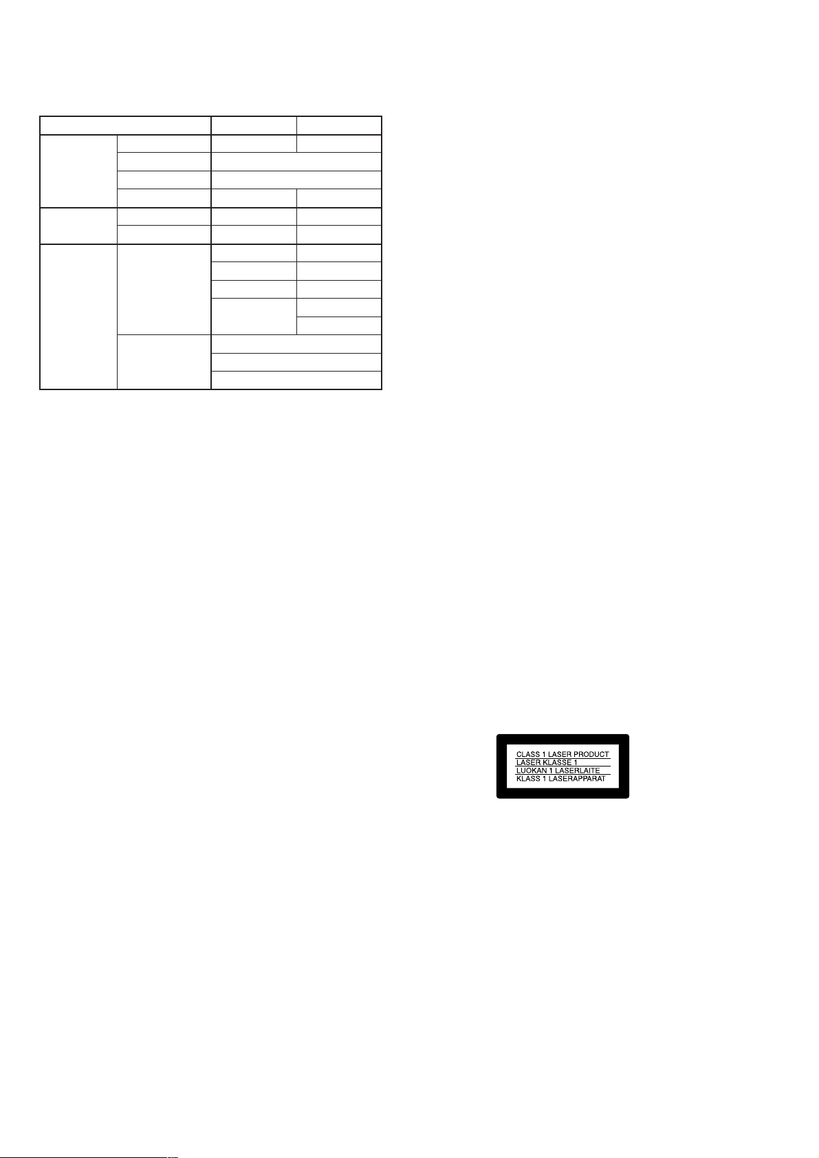
Table for difference of functions
Model
Lens Carl Zeiss lens
Optical zoom
Digital zoom
Filter diameter
CCD imager Size
Pixels
Image size Still
Movie
MVC-CD200
✕
37mm
1/2.7 type
2.1mega
1600×1200
1600 (3:2)
1024×768
640×480
320 (HQ)
320×240
640×480
MVC-CD300
a
3×
6×
52mm
1/1.8 type
3.3mega
2048×1536
2048 (3:2)
1600×1200
1280×960
640×480
SAFETY-RELATED COMPONENT WARNING!!
COMPONENTS IDENTIFIED BY MARK 0 OR DOTTED LINE WITH
MARK 0 ON THE SCHEMATIC DIAGRAMS AND IN THE PARTS
LIST ARE CRITICAL TO SAFE OPERATION. REPLACE THESE
COMPONENTS WITH SONY PARTS WHOSE PART NUMBERS
APPEAR AS SHOWN IN THIS MANUAL OR IN SUPPLEMENTS
PUBLISHED BY SONY.
SAFETY CHECK-OUT
After correcting the original service problem, perform the following
safety checks before releasing the set to the customer.
1. Check the area of your repair for unsoldered or poorly-soldered
connections. Check the entire board surface for solder splashes
and bridges.
2. Check the interboard wiring to ensure that no wires are
"pinched" or contact high-wattage resistors.
3. Look for unauthorized replacement parts, particularly
transistors, that were installed during a previous repair . Point
them out to the customer and recommend their replacement.
4. Look for parts which, through functioning, show obvious signs
of deterioration. Point them out to the customer and
recommend their replacement.
5. Check the B+ voltage to see it is at the values specified.
6. Flexible Circuit Board Repairing
• Keep the temperature of the soldering iron around 270˚C
during repairing.
• Do not touch the soldering iron on the same conductor of the
circuit board (within 3 times).
• Be careful not to apply force on the conductor when soldering
or unsoldering.
— 2 —
Page 3

TABLE OF CONTENTS
SERVICE NOTE ····································································· 5
1. MAIN PARTS
1. ORNAMENTAL PARTS ···················································· 7
2. DISASSEMBLY ································································· 8
2-1. LCD SECTION (PK-58 BOARD) ····································· 9
2-2. CABINET (FRONT) SECTION ······································ 10
2-3. CABINET (FRONT) ASSEMBLY (TK-61 BOARD),
CONTROL SWITCH BLOCK (RL-503) ························ 11
2-4. BATTERY HOLDER (JK-208 BOARD) ························· 12
2-5. SY-67 BOARD ································································· 12
2-6. STROBOSCOPE SECTION (FLASH UNIT) ················· 13
2-7. BASE UNIT (DDX-G2100 COMPLETE ASSEMBLY) · 13
2-8. LID CD SECTION ··························································· 14
2-9. FUNCTION BUTTON (FS-83 BOARD) ························ 14
2-10. SOLENOID PLUNGER (DOOR LOCK/STROBO-
SCOPE), CD LOCK SLIDER·········································· 15
2-11. CONTROL SWITCH BLOCK (ZK-503),
STRAP SHAFT ································································ 16
2-12. MODE KNOB, POWER SPRING ··································· 17
3. REPAIR PARTS LIST ······················································ 18
3-1. EXPLODED VIEWS ······················································· 18
3-1-1.OVERALL SECTION······················································ 18
3-1-2.CABINET (FRONT) SECTION, LENS CABINET
SECTION (CD200) ·························································· 19
3-1-3.CABINET (FRONT) SECTION, LENS CABINET
SECTION (CD300) ·························································· 20
3-1-4.LENS SECTION ······························································ 21
3-1-5.CABINET (REAR) SECTION-1 ····································· 22
3-1-6.CABINET (REAR) SECTION-2 ····································· 23
3-1-7.LID CD SECTION ··························································· 24
2. GENERAL
Introduction ············································································25
Getting started
Identifying the parts ································································ 25
Preparing the power supply ···················································· 25
Setting the date and time························································· 27
Inserting a disc ········································································ 27
Basic operations
B Recording
Initializing a disc (INITIALIZE) ············································ 28
Recording still images ···························································· 28
Recording moving images ······················································ 30
B Playback
Playing back still images ························································ 30
Playing back moving images ·················································· 30
Preparation for viewing images using a computer·················· 31
Viewing images using a computer ·········································· 32
Image file storage destinations and image file names ············ 34
Advanced operations
Before performing advanced operations
How to use the mode dial ······················································· 34
How to use the control button················································· 35
How to use the jog dial ···························································35
Menu settings·········································································· 35
Setting the image size (IMAGE SIZE) ··································· 36
B V arious recording
Recording with the exposure fixed (AE LOCK) ····················37
Recording with the manual adjustments································· 37
Recording images according to shooting conditions
(SCENE SELECTION) ·························································· 38
Recording three images continuously (BURST)
(only for MVC-CD300) ·························································· 38
Recording still images for e-mail (E-MAIL)·························· 38
Adding audio files to still images (VOICE) ··························· 38
Recording text documents (TEXT) ········································ 38
Recording still images as uncompressed files (TIFF) ············ 39
Recording three images with the exposure shifted
(only for MVC-CD300) (EXP BRKTG) ································ 39
Creating Clip Motion Files ····················································· 39
Setting the distance to the subject··········································· 40
Recording images in macro ···················································· 40
Adjusting the exposure (EXPOSURE) ··································· 40
Adjusting the white balance (WHITE BALANCE) ···············40
Enjoying picture effects (P. EFFECT) ···································· 40
Recording the date and time on the still image
(DATE/TIME)········································································· 41
Using the Spot light-metering function ·································· 41
B V arious playback
Playing back three or nine images at once······························ 41
Enlarging a part of the still image (Zoom and trimming)······· 41
Playing back the still images in order (SLIDE)······················ 42
Rotating a still image (ROTATE)············································ 42
Viewing images on a TV screen ············································· 42
B Editing
Deleting images (DELETE) ··················································· 42
Preventing accidental erasure (PROTECT) ····························43
Changing the recorded still image size (RESIZE)·················· 43
Selecting still images to print (PRINT) ·································· 43
Formatting a CD-RW······························································44
Changing the setup settings (SET UP) ··································· 44
Additional information
Precautions·············································································· 45
On discs ·················································································· 45
Using your camera abroad ······················································ 46
About “InfoLITHIUM” battery pack····································· 46
Troubleshooting ······································································ 46
Warning and notice messages ················································· 48
Self-diagnosis display ····························································· 49
LCD screen indicators ···························································· 49
— 3 —
Page 4
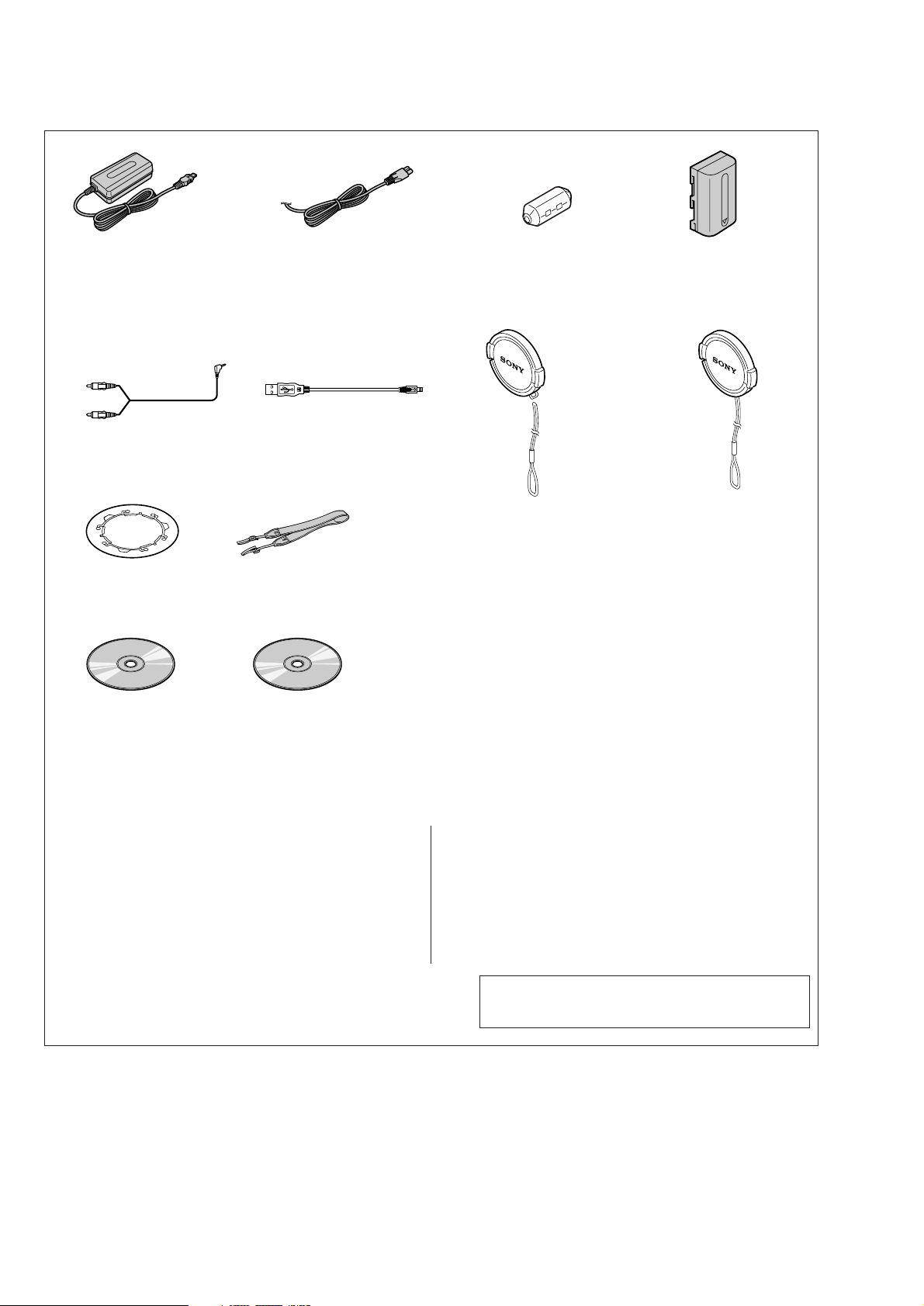
Checking supplied accessories
AC-L10A AC power adaptor (1)
0
1-475-599-11
A/V connecting cable (1.5m)(1)
1-783-738-31
8cm CD adaptor (1)
3-063-085-01
Power cord (main lead)(1) (AEP model)
0
1-769-608-11
Power cord (main lead)(with filter)(1)
(UK model)
0
1-783-374-11
USB cable (5P)(1)
1-757-293-31
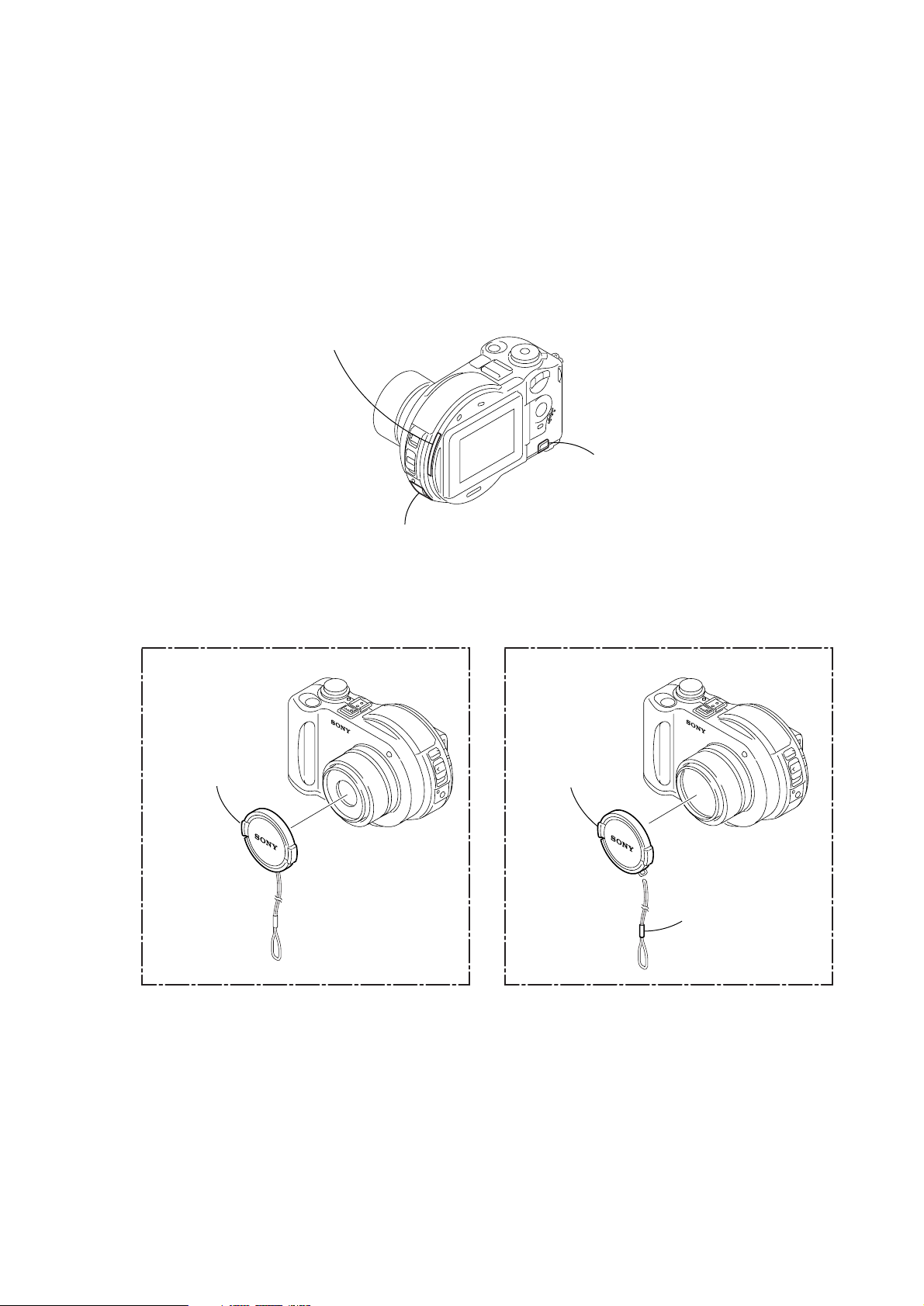
(Fig. A) Lens cap (1)(MVC-CD300)
(Fig. B) Lens cap strap (1)(MVC-CD300)
Shoulder belt (S) (1)
3-987-015-01
Mavica disc (2)(CD-R,CD-RW)
Not supplied
Clamp filter (ferrite core) (1)
1-543-798-11
(Fig. A)
(Fig. B)
X-3951-672-1
3-067-797-01
NP-FM50 battery pack (1)
Not supplied
Lens cap (1)(MVC-CD200)
X-3951-763-1
Application software:
Direct CD SPVD-006
(CD ROM) (1)
3-069-219-01
Application software:
USB driver SPVD-004 (P)
(CD-ROM)(1)
3-066-676-01
Other accessories
3-067-951-11 MANUAL,INSTRUCTION (ENGLISH)
3-067-951-21 MANUAL,INSTRUCTION (FRENCH/GERMAN)
3-067-951-31 MANUAL,INSTRUCTION (SPANISH/PORTUGEUSE)
3-067-951-41 MANUAL,INSTRUCTION (ITALIAN/DUTCH)
3-067-951-61 MANUAL,INSTRUCTION (SWEDISH)
(CD200:AEP/CD300:AEP)
(CD200:AEP/CD300:AEP)
(CD200:AEP/CD300:AEP)
(CD200:AEP/CD300:AEP)
3-067-952-11 MANUAL,INSTRUCTION (DIRECT CD)(ENGLISH)
3-067-952-21 MANUAL,INSTRUCTION (DIRECT CD)(FRENCH/GERMAN)
(CD200:AEP/CD300:AEP)
3-067-952-31 MANUAL,INSTRUCTION (DIRECT CD)
(SPANISH/PORTUGEUSE) (CD200:AEP/CD300:AEP)
3-067-952-41 MANUAL,INSTRUCTION (DIRECT CD)(ITALIAN/DUTCH)
(CD200:AEP/CD300:AEP)
3-067-952-61 MANUAL,INSTRUCTION (DIRECT CD)(SWEDISH)
(CD200:AEP/CD300:AEP)
Note : The components identified by mark 0 or dotted
line with mark 0 are critical for safety.
Replace only with part number specified.
— 4 —
Page 5
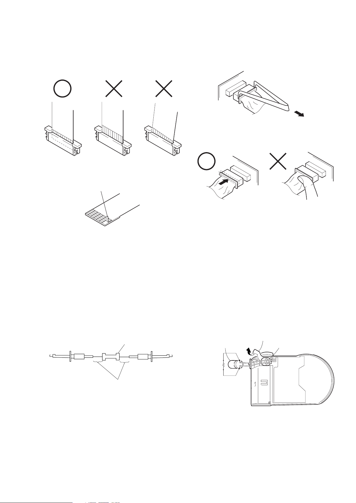
• NOTE FOR REPAIR
SERVICE NOTE
Make sure that the flat cable and flexible board are not cracked of
bent at the terminal.
Do not insert the cable insufficiently nor crookedly.
Cut and remove the part of gilt
which comes off at the point.
(Take care that there are
some pieces of gilt left inside)
When remove a connector, don't pull at wire of connector.
Be in danger of the snapping of a wire.
When installing a connector, don't press down at wire of connector.
Be in danger of the snapping of a wire.
[Discharging of the FLASH unit’s charging capacitor]
The charging capacitor of the FLASH unit is charged up to the
maximum 300 V potential.
There is a danger of electric shock by this high voltage when the
capacitor is handled by hand. The electric shock is caused by the
charged voltage which is kept without discharging when the main
power of the MVC-CD200/CD300 is simply turned off. Therefore,
the remaining voltage must be discharged as described below.
Preparing the Short Jig
To preparing the short jig. a small clip is attached to each end of a
resistor of 1 kΩ /1 W (1-215-869-11)
Wrap insulating tape fully around the leads of the resistor to prevent
electrical shock.
1 kΩ/1 W
Wrap insulating tape.
Discharging the Capacitor
Short circuits between the positive and the negative terminals of
charged capacitor with the short jig about 10 seconds.
Harness retainer
Capactior
Short jig
Capactior cap
— 5 —
Page 6
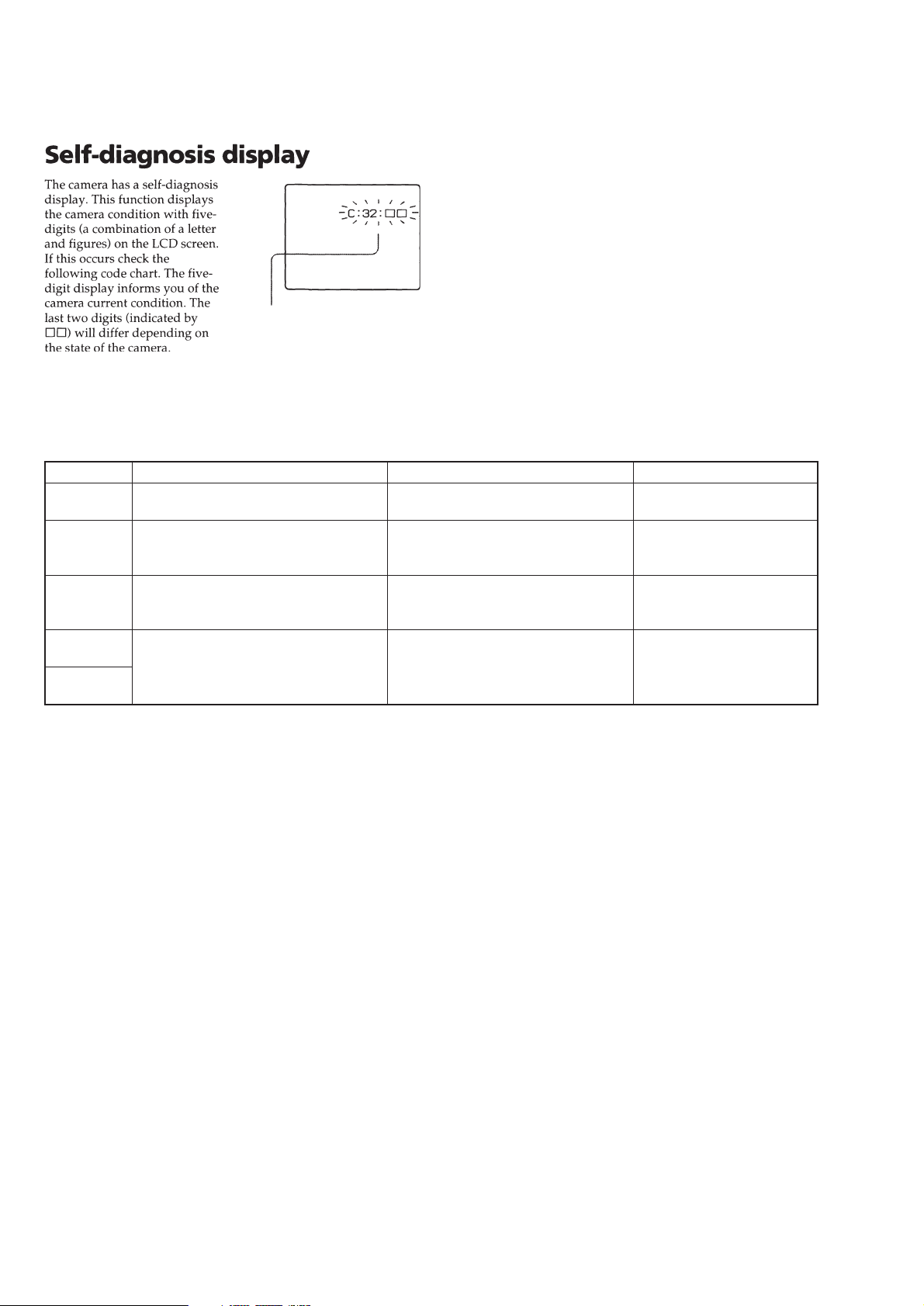
[Description on Self-diagnosis Display]
Self-diagnosis display
• C: ss: ss
The contents which can be handled
by customer, are displayed.
• E: ss: ss
The contents which can be handled
by engineer, are displayed.
Display Code
C:32:01
C:13:01
E:91:01
*1
E:61:00
*1
E:61:10
Note: The error code is cleared if the battery is removed.
*1 : The error display is given in two ways.
Change the disk and turn off the main
power then back on.
Replace the CD-R/RW disk.
Checking of flash unit or replacement of
flash unit
Checking of lens drive circuit
Countermeasure
Cause
Defective base unit.
• The type of CD-R/RW disk that cannot
be used by this machine, is inserted.
• Data is damaged.
Abnormality when flash is being
charged.
When failed in the focus initialization.
Caution Display During Error
DRIVE ERROR
DISK ERROR
Flash LED
Flash display
Flashing at 3.2 Hz
—
— 6 —
Page 7
1. MAIN PARTS
Note:
• Follow the disassembly procedure in the numerical order given.
• Items marked “*” are not stocked since they are seldom required for routine service.
Some delay should be anticipated when ordering these items.
• The parts numbers of such as a cabinet are also appeared in this section.
Refer to the parts number mentioned below the name of parts to order.
1. ORNAMENTAL PARTS
CPC lid
3-067-950-11 (CD200)
3-067-950-01 (CD300)
Note: Disassembling the main unit
is necessary to replace it.
MVC-CD200/CD300
DC cover
3-068-424-01
Note: Disassembling the main unit
is necessary to replace it.
Lens cap assembly
X-3951-763-1
JK cover
3-067-941-11 (CD200)
3-067-941-01 (CD300)
Note: Disassembling the main unit
is necessary to replace it.
(CD300)(CD200)
Lens cap assembly
X-3951-672-1
Cap string (T)
3-067-797-01
— 7 —
Page 8

2. DISASSEMBLY
The following flow chart shows the disassembly procedure.
2-1. LCD section (PK-58 board)
2-2. Cabinet (front) section
2-4. Battery holder (JK-208 board)
2-5. SY-67 board
2-6. Stroboscope section
2-7. Base unit (DDX-G2100 complete assembly)
2-8. Lid CD section
MVC-CD200/CD300
2-9. Function button (FS-83 board)
2-10. Solenoid plunger (Door lock/Stroboscope),
CD lock slider
2-3. Cabinet (front) assembly (TK-61 board),
Control switch block (RL-503)
2-11. Control switch block (ZK-503), Strap shaft
2-12. Mode knob, Power spring
— 8 —
Page 9
NOTE: F ollo w the disassembly procedure in the numerical order given.
2-1. LCD SECTION (PK-58 BOARD)
5 PK-58
board
Remove the CD rear lid in the
direction of the arrow A.
A
3 Four precision
screws (DIA 1.7 × 4)
1 T wo precision
screws (DIA 1.7 × 4)
2 Flexible
cover (CD)
4 Precision
screw
(DIA 1.7 × 5)
3 T wo precision
screws (DIA 1.7 × 4)
Upper stay assembly
PK-58
B
4 Precision
screw (DIA 1.7 × 4)
1 Liquid crystal indicator
module (24P)
2 Back light
(10P)
1 T wo precision
screws (DIA 1.7 × 4)
Remove the PK-58
board in the direction
of the arrow B.
PK-58
PK-58
6 CD rear
lid
5 CPC lid
2 T wo precision
screws (DIA 1.7 × 4)
3 BL retainer plate
4 Back light
Cold cathode
fluorescent tube
5 Liquid crystal
indicator module
6 Solar window
— 9 —
Page 10
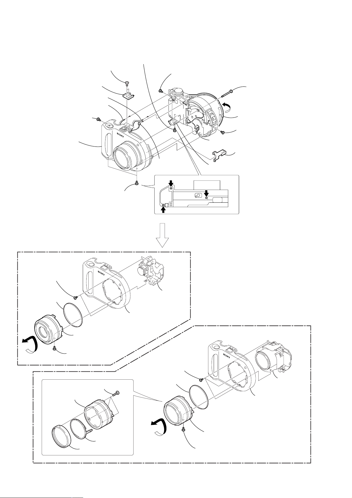
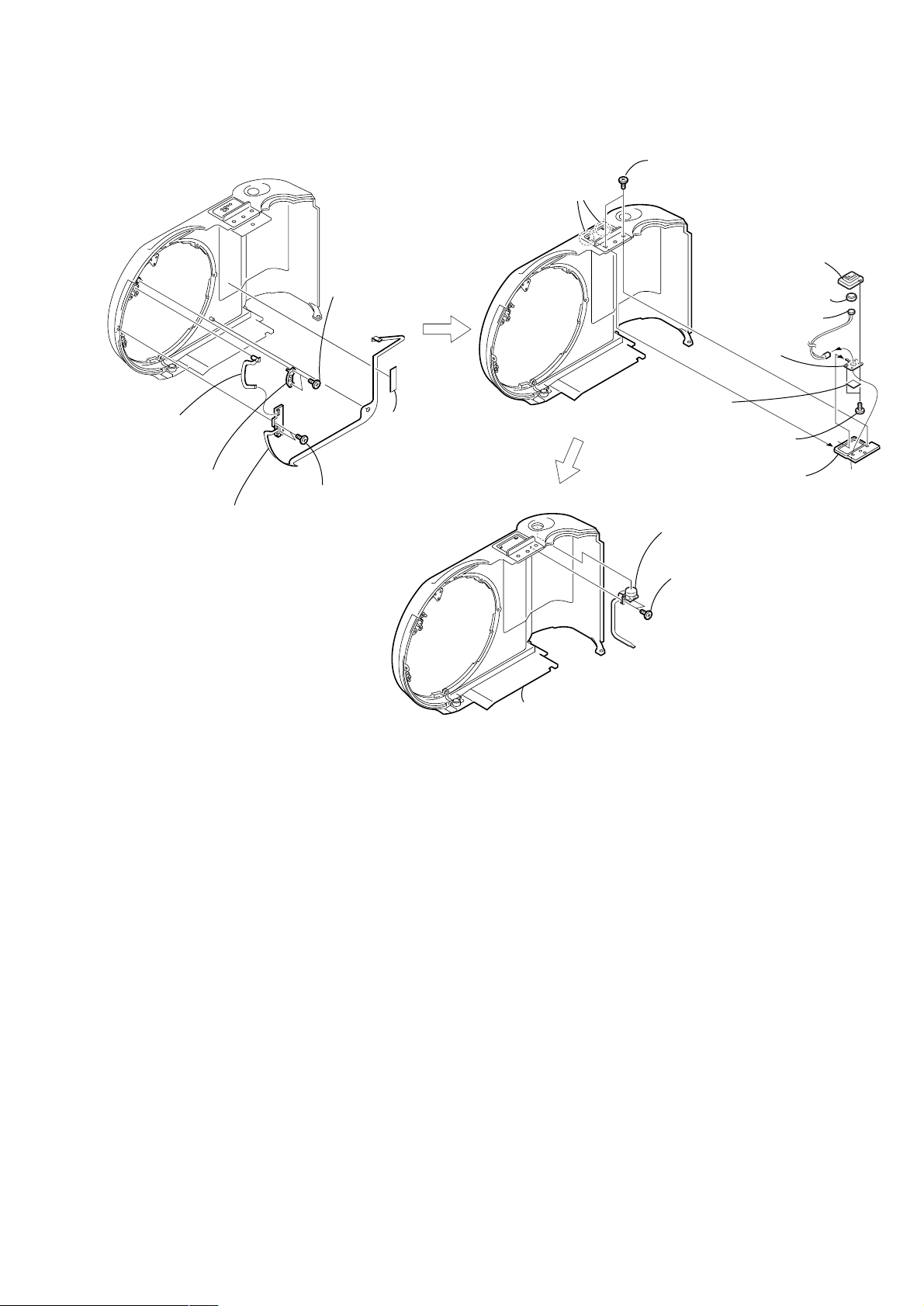
2-2. CABINET (FRONT) SECTION
3 T wo screws
(M 2 × 3.5)
4 Accessory
shoe
qf FP-369 flexible board (5P)
qg Control switch block
(RL-503) (6P)
7 Screw (M 2 × 4),
lock ace, P2
qh Cabinet (front) section,
Lens cabinet section,
Lens section
0 Two screws (M 2 × 4),
lock ace, P2
9 Screw (M 2 × 4),
lock ace, P2
6 Screw (M 2 × 4),
lock ace, P2
SY-67
qd Microphone
(2P)
JK-208
qs FP-364 flexible
board (70P)
8 Open the
BT lid
2 Special (step)
screw (M 2)
1 Open the lid
CD section
5 Screw (M 2 × 4),
lock ace, P2
qa BIB retainer
(CD200)
4 Two screws (M 2 × 4),
lock ace, P2
3 Ornamental ring
A
4 Lens cabinet (H)
6 Cabinet (front) section
2 Remove the lens cabinet assembly
in the direction of the arrow A.
1 Screw (M 2 × 4),
lock ace, P2
1 Three screws (M 1.7 × 7)
5 Lens
section
4 Three screws (M 2 × 4),
lock ace, P2
3 Ornamental ring
B
(CD300)
5 Lens
section
6 Cabinet (front) section
3 LC switch
2 Filter ring
— 10 —
2 Remove the lens cabinet assembly
in the direction of the arrow B.
1 Screw (M 2 × 4),
lock ace, P2
Page 11
2-3. CABINET (FRONT) ASSEMBLY (TK-61 BOARD), CONTROL SWITCH BLOCK (RL-503)
1 T wo screws
(M 1.7 × 2),
lock ace, P2
6 Microphone holder
assembly
7 Microphone cushion
4 Microphone
sheet
5 T wo tapping
screws (B 1.7 × 3.5)
3 Rear sheet
metal (upper)
2 Control switch
block (RL-503)
8 Microphone
9 Retainer
sheet
metal
4 FP-370 flexible
board (5P),
LED
2 LED cap
6 TK-61 board,
FP-369 flexible
board
2 T wo claws
1 T wo precision
screws
(DIA 1.7 × 4)
5 T ape (A)
3 T wo precision
screws
(DIA 1.7 × 4)
3 Cabinet (front) assembly
1 T wo precision
screws
(DIA 1.7 × 4)
— 11 —
Page 12
2-4. BATTERY HOLDER (JK-208 BOARD)
4 Remove the BT holder assembly
in the direction of the arrow A.
REMOVING THE BATTERY HOLDER
8 Battery holder
3 BT lid
retainer
1 T wo tapping
screws
(1.7 × 3)
7 Battery spring
6 Battery terminal
board
2 BT lid
4 BT sheet
5 Two
claws
5 Battery terminal
board (3P)
6 BT holder
assembly
3 Precision
screw
(DIA 1.7 × 4)
A
1 Open the
BT lid
7 T wo precision
screws
(DIA 1.7 × 4)
FS-83
2 Screw
(M 2 × 4),
lock ace, P2
(CD200)
8 SJ sheet
9 JK sheet
SY-67
JK
-208
(CD300)
8 JK-208 board,
FP-361 flexible board
0 JK-208 board,
FP-361 flexible
JK-208
board
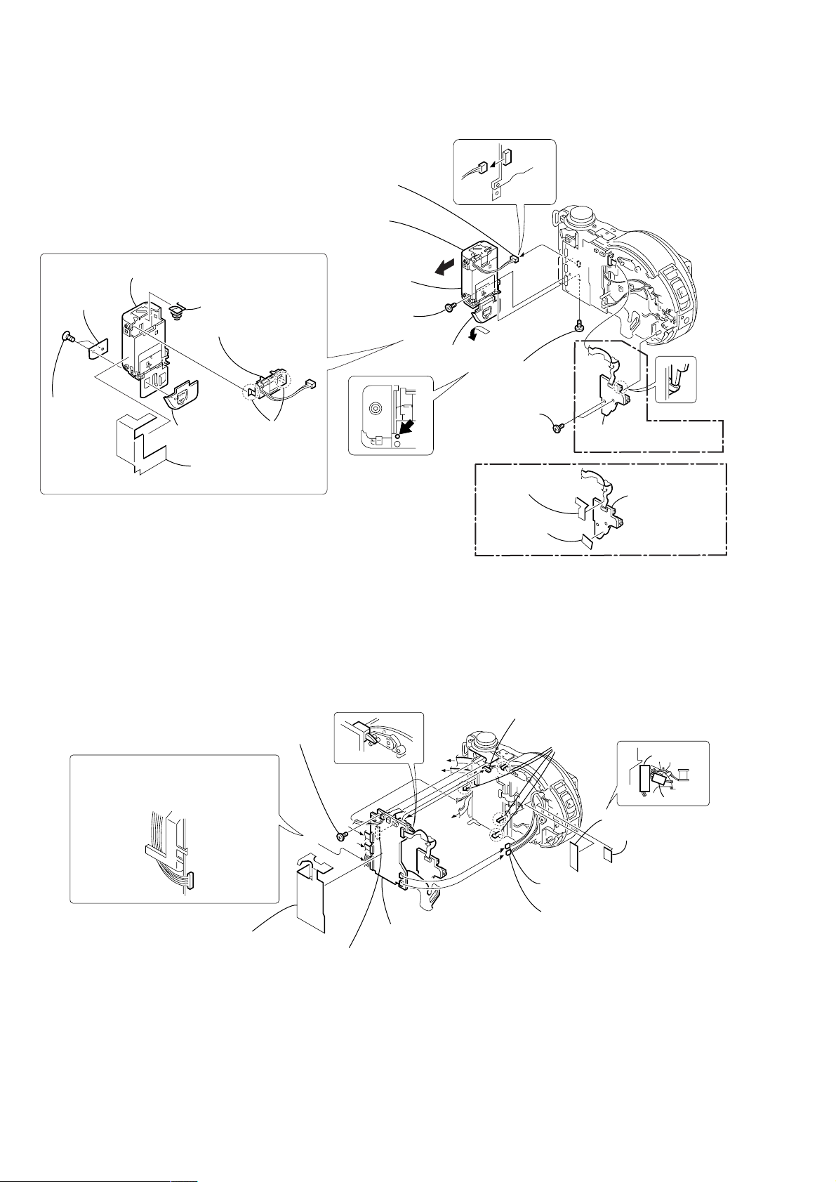
2-5. SY-67 BOARD
When attaching the connector, route
the harnesses through the notch as
shown while taking care so the the
harness must not be caught or pinched.
7 Precision screw
(DIA 1.7 × 4)
1 Harness retainer
A
C
B
SY-67
0 SY-67 board, JK-208 board,
9 Remove the connector
FP-361 flexible board, FP-364 flexible board
6 Harness
(from flash unit 8P)
B
A
C
MD083
8 Four
claws
2 T ape (A)
Tape (A)
Tape (Z)
3 T ape (Z)
JK
-208
4 Harness (FS-139) (2P)
(strobe plunger)
5 Harness (FS-140) (2P)
(dew sensor)
— 12 —
Page 13
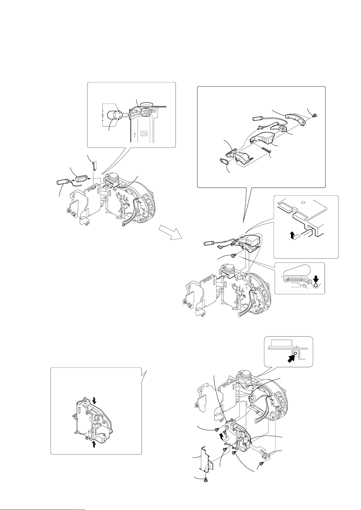
2-6. STROBOSCOPE SECTION (FLASH UNIT)
)
Note: The charging capacitor is charged to the maximum of 300V.
There is a danger of electric shock due to the high voltage when the capacitor is touched by bare hand.
Discharge the voltage remained in the capacitor, referring to the Service Note (See page 5).
1 Capacitor cap
2 Capacitor
4 Sheet (UW)
SY-
JK208
67
3 Discharging the capacitor
Short jig
Capacitor cap
Capacitor
5 Control switch block
(ZK-503) (14P)
MD083
3 Stroboscope
base
1 Precision screw
(DIA 1.7 × 4)
6 Stroboscope
cover
1 ST sensor
lever
4 T wo precision
screws
(DIA 1.7 × 4)
7 Flash unit
5 Stroboscope
case assembly
2 ST-POP-UP
spring
A
2 Remove the stroboscope
section in the direction
of the arrow A.
JK208
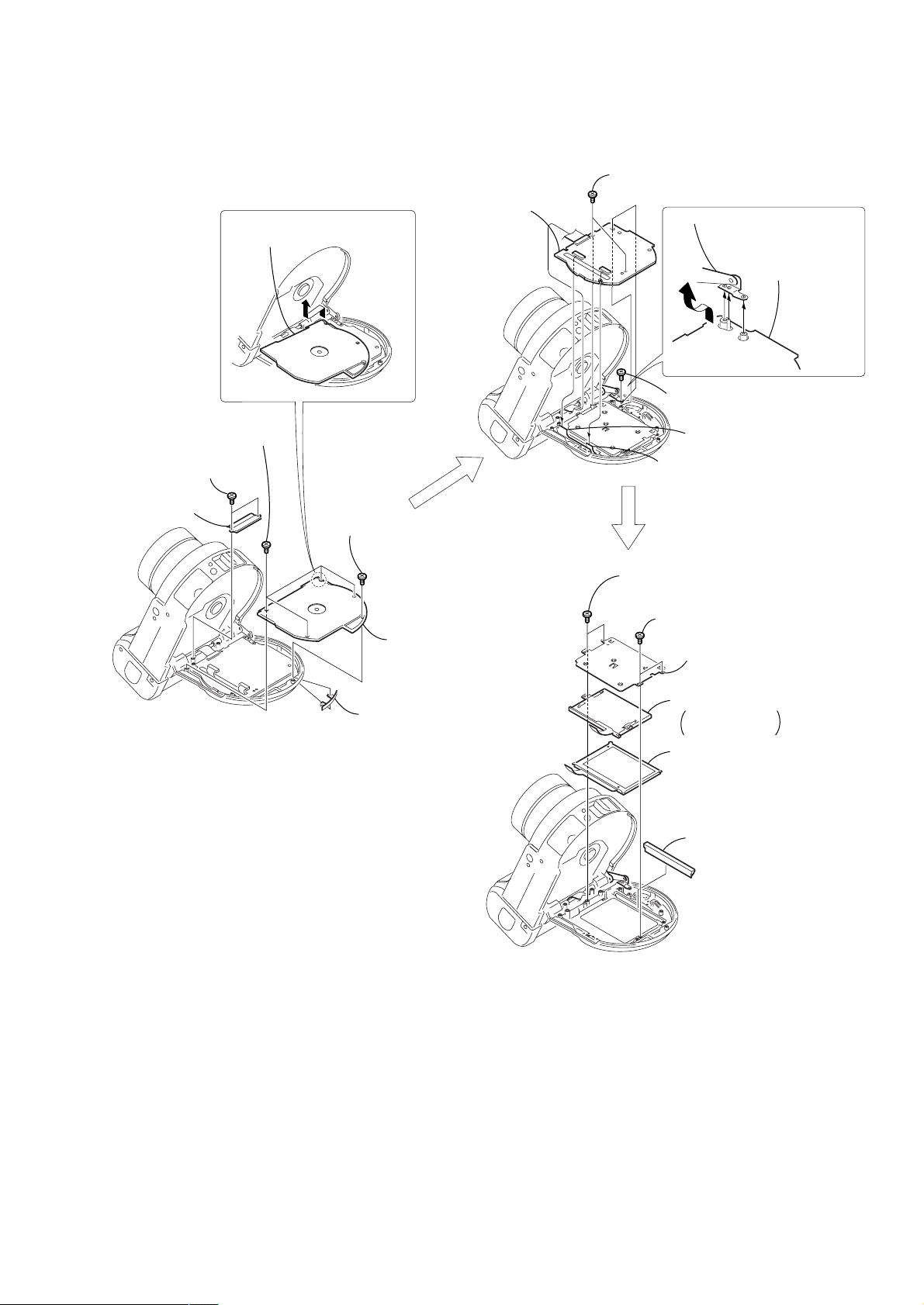
2-7. BASE UNIT (DDX-G2100 COMPLETE ASSEMBLY)
Precautions during handling
• Do not turn the side of the optical
lens downward.
• Hold the frame.
• Do not touch the optical lens surface.
MD083
7 Remove the DDX-G2100 complete
assembly in the direction of the arrow.
5 T wo precision
screws
(DIA 1.7 × 4)
9 MD heat sink,
MD sheet
8 Precision screw
(DIA 1.7 × 4)
JK208
SY67
MD083
SY67
MD083
6 Precision
screw
(DIA 1.7 × 4)
1 Harness (FS-138) (2P
(door look plunger)
3 Harness (SF-81)
4 Nut plate (side)
2 T wo precision
screws (DIA 1.7 × 4)
— 13 —
Page 14
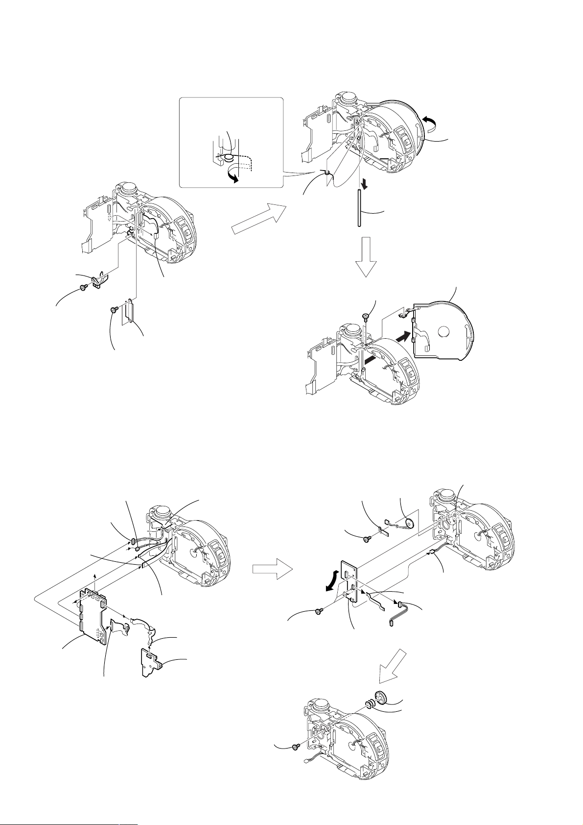
2-8. LID CD SECTION
Remove the PRE open
spring in the direction of the
arrow C.
C
SY67
FS-83
1 Open the lid
CD section
FS-83
SY67
2 Parallel
pin cover
5 FP-363 flexible
board (33P)
1 Precision
screw
(DIA 1.7 × 4)
4 Flexible cover (CD)
3 T wo precision
screws
(DIA 1.7 × 4)
2-9. FUNCTION BUTTON (FS-83 BOARD)
3 PRE
open spring
1 T wo screws
(M 1.7 × 3), P2
SY67
A
2 Remove the Parallel pin (DIA 3)
in the direction of the arrow A.
2 Remove the lid CD section in
the direction of the arrow B.
B
FS-83
8 Harness
(FS-136) (14P)
6 FP-363 flexible
board (33P)
B
A
SY -67
9 SY-67 board
1 FP-364 flexible
board (70P)
5 Speaker (2P)
B
A
7 FP-362 flexible
board (11P)
JK
-2
08
4 Control switch block
(ZK-503) (14P)
2 FP-361 flexible
board (27P)
3 JK-208 board
1 Special head screw
(M 1.7 × 3)
7 Precision
screw
(DIA 1.7 × 4)
1 Three
precision
screws
(DIA 1.7 × 4)
8 Speaker
retainer
FS-83
9 Speaker
4 FP-362 flexible board (11P)
3 Remove the FS-83 board
in the direction of the arrow.
3 Function button
2 F button spring
2 Dowel
6 DC-IN
connector (3P)
5 Harness
(FS-136) (14P)
— 14 —
Page 15
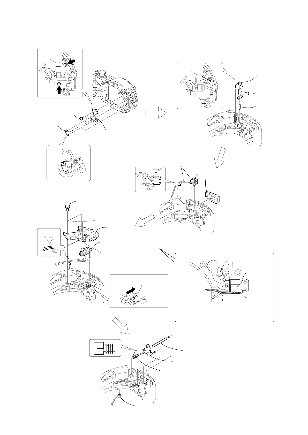
2-10. SOLENOID PLUNGER (DOOR LOCK/STROBOSCOPE), CD LOCK SLIDER
r
1 CD lock
lever spring
2 CD lock leve
2 T wo precision
screws
(DIA 1.7 × 4)
1 CD opener
spring
3 Solenoid cover
2 Four precision
screws
(DIA 1.7 × 4)
3 ST lock
cover
4 Solenoid plunger
(stroboscope), Harness (FS-139)
1 Solenoid plunger (door lock),
Harness (FS-138)
#
2 CD opener
assembly
3
3 Parallel pin
(DIA 1.6 × 6)
1 Remove the CD lock spring
in the direction of the arrow.
1 CD lock spring
4 FP-248 flexible board (dew sensor) ,
Harness (FS-140)
Spring
When attaching the solenoid plunger, route the
harnesses through the notch as shown while
taking care so that the harness must not be
caught or pinched.
2 Parallel pin
3 CD lock slider
#
3
— 15 —
Page 16
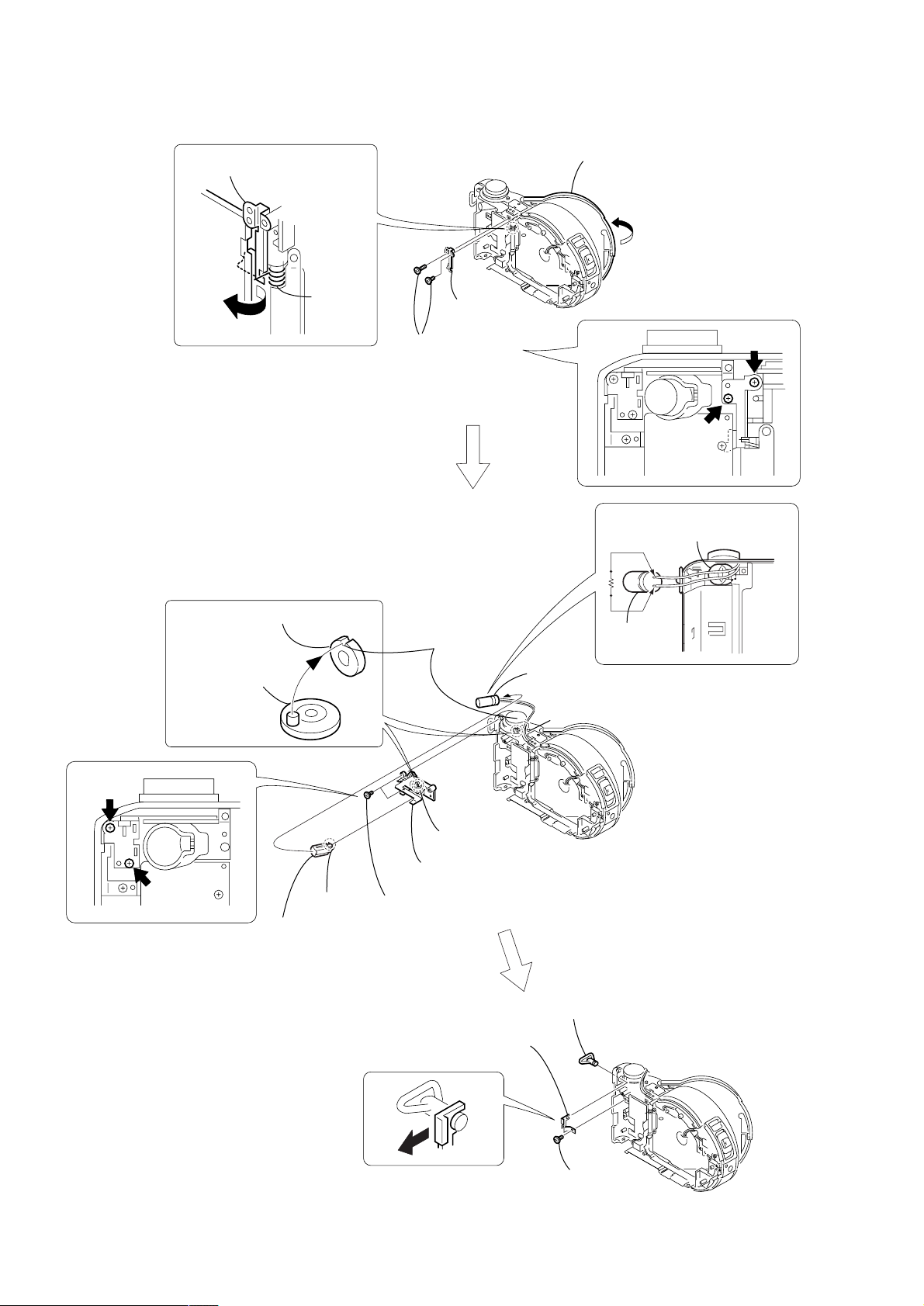
2-11. CONTROL SWITCH BLOCK (ZK-503), STRAP SHAFT
Remove the PO spring stay in
the direction of the arrow A.
FS-83
A
PRE open
spring
PRECAUTION DURING
INSTALLATION
FS-83
3 PO spring
stay
2 Two screws
(DIA 1.7 × 5.5)
1 Open the lid
CD section
Discharging the capacitor
Short jig
Capacitor cap
Mode knob
retainer
Control switch
block (ZK-503)
5 Claw
6 Capacitor
cap
"S" position
set in live A
3 Dowel
4 Control switch block
(ZK-503)
2 T wo precision
screws
(DIA 1.7 × 4)
2 Strap sheet
metal (R)
1 Capacitor
A
s
FS-83
Capacitor
3 Strap shaft
— 16 —
FS-83
1 Precision
screw
(DIA 1.7 × 4)
Page 17

2-12. MODE KNOB, POWER SPRING
"S" position set in live A
3 Mode knob
retainer
2
s
A
1 Special head screw
(M 1.7 × 3 )
7 Mode knob
6 Dial base
5 Click plate
4 Three EG grip
screws (M 1.4 × 2.5)
8 Friction spring
When attaching it, coat the
hatched portion with grease.
Click
Rear view
Note: Perform the running-in rotation of the
click plate several times.
plate
0 Power knob
Rear view
9 Slider ring
— 17 —
qa Power spring
Page 18

3. REPAIR PARTS LIST
3-1. EXPLODED VIEWS
NOTE:
• -XX, -X mean standardized parts, so they may
have some differences from the original one.
• Items marked “*” are not stocked since they
are seldom required for routine service. Some
delay should be anticipated when ordering these
items.
3-1-1. OVERALL SECTION
not
supplied
8
5
Cabinet (front) section,
Lens cabinet section (See page 20),
Lens section (See page 21)
(CD300)
9
J
10
BT901
6
4
3
2
• The mechanical parts with no reference number
in the exploded views are not supplied.
K
13
11
E
5
B
5
12
A
D
F
C
SY-67
7
K
15
not
supplied
G
H
I
16
(Note)
5
5
17
MD-083
18
5
The components identified by mark 0 or
dotted line with mark 0 are critical for safety.
Replace only with part number specified.
Cabinet (rear) section,
(See page 22, 23)
2
5
F
E
B
J
C
A
2
H
I
D
G
21
5
(CD200)
24
23
19
14
25
2
20
22
JK-208
5
2
1
26
not
supplied
1
2
: BT101(Lithium battery) JK-208 board on the mount position.
Note: The charging capacitor is charged to the maximum of 300V.
There is a danger of electric shock due to the high voltage when the capacitor is touched by bare hand.
Discharge the voltage remained in the capacitor, referring to the Service Note (See page 5).
Ref. No. Part No. Description Remarks Ref. No. Part No. Description Remarks
1 X-3951-672-1 CAP ASSY, LENS (CD300)
1 X-3951-763-1 CAP ASSY, LENS (CD200)
2 3-968-729-71 SCREW (M2), LOCK ACE, P2
3 3-067-469-11 SHOE, ACCESSORY
4 3-069-159-21 PROCESS, (M2) INTERIOR LOCK
5 3-914-366-01 SCREW (DIA. 1.7X4), PRECISION
6 3-067-937-01 LID, BT (CD300)
6 3-067-937-11 LID, BT (CD200)
7 3-068-462-01 SPRING, ST-POP-UP
8 3-318-382-01 SCREW (1.7X3), TAPPING
13 3-068-461-01 BASE, STROBOSCOPE
14 3-067-950-01 LID, CPC (CD300)
14 3-067-950-11 LID, CPC (CD200)
15 X-3951-647-1 CASE ASSY, STROBOSCOPE (CD300)
15 X-3951-655-1 CASE ASSY, STROBOSCOPE (CD200)
0 16 not supplied FLASH UNIT
17 3-067-949-01 COVER, STROBOSCOPE (CD300)
17 3-067-949-11 COVER, STROBOSCOPE (CD200)
18 not supplied DDX-G2100 COMPLETE ASSY (SERVICE)
19 3-068-474-01 SCREW (M2), SPECIAL (STEP)
Cabinet (front) section,
Lens cabinet section
(See page 19),
Lens section
(See page 21)
9 3-969-380-01 SPRING, BATTERY
10 X-3951-639-1 HOLDER ASSY, BT (CD300)
10 X-3951-651-1 HOLDER ASSY, BT (CD200)
11 3-068-464-01 LEVER, ST SENSOR
12 not supplied SY-67 (300) BOARD, COMPLETE (SERVICE)
(CD300)
12 not supplied SY-67 (200) BOARD, COMPLETE (SERVICE)
(CD200)
20 1-681-545-11 FP-361 FLEXIBLE BOARD
21 3-068-475-01 NUT PLATE (SIDE)
22 not supplied JK-208 BOARD, COMPLETE
23 3-068-875-01 RETAINER, B2B
24 1-681-548-21 FP-364 FLEXIBLE BOARD
25 3-713-791-11 SCREW (M1.7X5), TAPPING, P2
26 3-067-797-01 STRING (T), CAP (CD300)
BT901 1-694-815-11 TERMINAL BOARD, BATTERY
— 18 —
Page 19

3-1-2. CABINET (FRONT) SECTION, LENS CABINET SECTION
(CD200)
52
51
A
51
55
not
supplied
51
57
B
56
53
MIC901
54
B
61
53
58
63
60
62
59
not
supplied
53
LED901
65
64
Lens section (See page 21)
53
67
66
53
A
Ref. No. Part No. Description Remarks Ref. No. Part No. Description Remarks
51 3-968-729-71 SCREW (M2), LOCK ACE, P2
52 X-3951-650-1 CABINET ASSY, LENS
53 3-914-366-01 SCREW (DIA. 1.7X4), PRECISION
54 3-060-274-01 SCREW, TRIPOD
55 X-3951-652-1 CABINET (FRONT) ASSY
56 3-989-735-61 SCREW (M1.7), LOCK ACE, P2
57 1-476-674-11 SWITCH BLOCK, CONTROL (RL-503)
58 3-067-948-11 PLATE, SIDE ORNAMENTAL
59 3-713-791-05 SCREW (B1.7)
60 3-068-402-01 SHEET METAL, RETAINER
61 3-068-488-01 CUSHION, MICROPHONE
62 3-062-299-01 SHEET, MICROPHONE
63 X-3951-646-1 HOLDER ASSY, MICROPHONE
64 1-681-549-11 FP-369 FLEXIBLE BOARD
65 not supplied TK-61 (200) BOARD, COMPLETE
66 1-681-550-11 FP-370 FLEXIBLE BOARD
67 3-068-494-01 CAP, LED
LED901 8-719-084-32 DIODE TLOH20TP
MIC901 1-542-457-11 MICROPHONE
— 19 —
Page 20

3-1-3. CABINET (FRONT) SECTION, LENS CABINET SECTION
(CD300)
101
not
supplied
104
not
supplied
103
A
102
108
110
102
B
109
106
105
B
113
MIC901
106
107
115
112
114
111
not
supplied
117
106
LED901
116
106
118
106
119
Lens section
(See page 21)
A
102
Ref. No. Part No. Description Remarks Ref. No. Part No. Description Remarks
101 3-068-411-01 RING, FILTER
102 3-968-729-71 SCREW (M2), LOCK ACE, P2
103 3-060-271-01 SCREW (M1.7X7)
104 X-3951-642-1 CABINET ASSY, LENS
105 3-060-274-01 SCREW, TRIPOD
106 3-914-366-01 SCREW (DIA. 1.7X4), PRECISION
107 3-067-948-01 PLATE, SIDE ORNAMENTAL
108 X-3951-641-1 CABINET (FRONT) ASSY
109 3-989-735-61 SCREW (M1.7), LOCK ACE, P2
110 1-476-674-11 SWITCH BLOCK, CONTROL (RL-503)
111 3-713-791-05 SCREW (B1.7)
112 3-068-402-01 SHEET METAL, RETAINER
113 3-068-488-01 CUSHION, MICROPHONE
114 3-062-299-01 SHEET, MICROPHONE
115 X-3951-646-1 HOLDER ASSY, MICROPHONE
116 1-681-549-11 FP-369 FLEXIBLE BOARD
117 not supplied TK-61 BOARD, COMPLETE
118 1-681-550-11 FP-370 FLEXIBLE BOARD
119 3-068-494-01 CAP, LED
LED901 8-719-084-32 DIODE TLOH20TP
MIC901 1-542-457-11 MICROPHONE
— 20 —
Page 21

3-1-4. LENS SECTION
(CD200)
not
supplied
(CD300)
160
M001
not
supplied
151
152
M002
154
153
154
155
156
IC101
157
not
supplied
CD-333
161
158
159
162
163
IC401
164
not
supplied
165
166
167
CD-334
Ref. No. Part No. Description Remarks Ref. No. Part No. Description Remarks
151 3-831-441-11 SPACER (CD200)
152 not supplied LENS, ZOOM (VCL-6103WA) (CD200)
153 3-068-533-01 FRAME (M), LENS (CD200)
154 3-914-366-01 SCREW (DIA. 1.7X4), PRECISION (CD200)
155 not supplied ADAPTOR (CL), CCD FITTING (CD200)
156 not supplied FILTER BLOCK, OPTICAL (CD200)
157 not supplied RUBBER (CL), SEAL (CD200)
158 not supplied CD-333 BOARD, COMPLETE (CD200)
159 not supplied TITE (2), +B TAPPING (P) (CD200)
160 not supplied FRAME (H), LENS (CD300)
161 not supplied LENS ASSY (CD300)
162 not supplied SCREW (M1.7), LOCK ACE, P2 (CD300)
163 not supplied FILTER BLOCK, OPTICAL (CD300)
164 not supplied RUBBER (N), SEAL (CD300)
165 not supplied SCREW (B1.7) (CD300)
166 not supplied CD-334 BOARD, COMPLETE (CD300)
167 not supplied SCREW (B1.7X6), TAPPING (CD300)
IC101 not supplied CCD BLOCK ASSY (CCD IMAGER) (CD200)
IC401 not supplied CCD BLOCK ASSY (CCD IMAGER) (CD300)
M001 not supplied MOTOR UNIT, FOCUS (CD200)
M002 not supplied MOTOR UNIT, ZOOM (CD200)
— 21 —
Page 22

3-1-5. CABINET (REAR) SECTION-1
Lid CD section
(See page 24)
203
205
201
206
202
205
C
218
B
FS-83
205
215
217
SP901
J901
216
207
205
205
208
214
B
204
205
209
C
213
212
A
211
A
Cabinet (rear) section-2
(See page 23)
210
Ref. No. Part No. Description Remarks Ref. No. Part No. Description Remarks
201 3-069-046-01 SCREW (Y) (DIA. 1.7X5.5)
202 3-070-017-01 STAY, PO SPRING
203 3-068-479-01 CAP, CAPACITOR
204 3-070-014-01 SPRING, PRE OPEN
205 3-914-366-01 SCREW (DIA. 1.7X4), PRECISION
206 1-476-675-11 SWITCH BLOCK, CONTROL (ZK-503)
207 3-068-454-01 SHEET METAL (R), STRAP
208 3-068-457-01 SHAFT, STRAP
209 3-056-559-11 SCREW (M1.7), 0 PART-NO. P2
210 1-657-785-11 FP-248 FLEXIBLE BOARD (DEW SENSOR)
211 1-961-144-11 HARNESS (FS-140)
212 3-068-496-01 PIN (DIA. 3), PARALLEL
213 3-068-450-01 COVER (CD), FLEXIBLE
214 3-068-497-01 COVER, PARALLEL PIN
215 3-068-453-01 RETAINER, SPEAKER
216 1-961-141-11 HARNESS (FS-136)
217 1-681-546-11 FP-362 FLEXIBLE BOARD
218 not supplied FS-83 BOARD, COMPLETE
J901 1-794-045-11 CONNECTOR, DC-IN
SP901 1-544-839-11 SPEAKER (1.6 CM)
— 22 —
Page 23

3-1-6. CABINET (REAR) SECTION-2
A
A
B
B
C
252
257
258
259
251
252
253
254
277
273
255
256
260
261 272
271
256
275
280
279
277
278
not
supplied
PL902
PL901
not
supplied
270
262
264
266
268
269
267
265
263
274
C
252
276
269 3-068-536-01 KNOB (M), MODE (CD200)
* 270 3-064-250-01 SPRING, F BUTTON
271 3-067-942-01 BUTTON, FUNCTION (CD300)
271 3-067-942-11 BUTTON, FUNCTION (CD200)
272 3-068-424-01 COVER, DC
273 X-3951-648-1 OPENER ASSY, CD (CD300)
273 X-3951-656-1 OPENER ASSY, CD (CD200)
274 3-067-941-01 COVER, JK (CD300)
274 3-067-941-11 COVER, JK (CD200)
275 1-961-143-11 HARNESS (FS-139)
276 3-068-455-01 SHEET METAL (L), STRAP
277 3-065-177-01 SCREW (1.7X3)
278 3-068-421-01 RETAINER, MODE KNOB
279 3-068-401-01 HEAD (M1.7),0 PART-NO. SPECIAL
280 X-3951-643-1 CABINET (REAR) ASSY (CD300)
280 X-3951-653-1 CABINET (REAR) ASSY (CD200)
PL901 1-454-674-51 SOLENOID, PLUNGER (STOROBO PLUNGER)
PL902 1-454-988-11 SOLENOID, PLUNGER (DOOR LOCK PLUNGER)
Ref. No. Part No. Description Remarks Ref. No. Part No. Description Remarks
251 3-068-467-01 SPRING, CD OPENER
252 3-914-366-01 SCREW (DIA. 1.7X4), PRECISION
253 3-068-470-01 COVER, SOLENOID
254 3-068-469-01 SPRING, CD LOCK LEVER
255 3-068-468-01 LEVER, CD LOCK
256 3-703-357-03 PIN, PARALLEL (DIA. 1.6X6)
257 1-961-142-11 HARNESS (FS-138)
258 3-068-481-01 COVER, ST LOCK
259 3-068-427-01 SPRING, CD LOCK
260 3-649-266-01 PIN, PARALLEL
261 3-068-428-01 SLIDER, CD LOCK
262 3-068-423-01 SPRING, POWER
263 3-068-422-01 KNOB, POWER
264 3-068-493-01 RING, SLIDER
265 3-068-625-01 SPRING, FRICTION
266 3-068-597-01 GRIP (M1.4), EG
267 3-068-623-01 PLATE, CLICK
268 3-068-619-01 BASE, DIAL
269 3-068-420-01 KNOB, MODE (CD300)
— 23 —
Page 24

3-1-7. LID CD SECTION
LCD901
304
301
302
301
301
305
303
PK-58
301
B
A
not
supplied
301
301
A
306
307
B
ND901
Ref. No. Part No. Description Remarks Ref. No. Part No. Description Remarks
301 3-914-366-01 SCREW (DIA. 1.7X4), PRECISION
302 3-068-459-01 LID, CD REAR
303 not supplied PK-58 (SH) BOARD, COMPLETE
304 1-681-547-11 FP-363 FLEXIBLE BOARD
305 X-3951-645-1 STAY ASSY, UPPER
— 24 —
306 3-068-458-01 WINDOW, SOLAR
307 X-3951-644-1 LID ASSY, CD (CD300)
307 X-3951-654-1 LID ASSY, CD (CD200)
LCD901 not supplied INDICATOR MODULE LIQUID CRYSTAL
(LQ25A3FR30) (SERVICE)
0 ND901 not supplied TUBE, FLUORESCENT,COLD CATHODE
Note : The components identified by mark 0 or dotted
line with mark 0 are critical for safety.
Replace only with part number specified.
Page 25

2. GENERAL
6
Introduction
Captures images with your computer
You can easily copy images onto your com puter through a CD-ROM drive, CD-R
drive, CD-RW drive, or the USB cable and view and modify images on your
computer using application software. When using a CD-ROM drive to view images
on your computer, the finalizat ion is required (page 32).
Flow chart for disc operations
Start
• A new disc
• The disc finalized with a computer or other equipmen t
Initialize
(page 18)
Disc preparation for
recording is complete.
The disc status
is before
finalization
Blank disc
Record
[About 1 min]
(page 32)
About 13 MB disc
space is used
Unfinalize
[About 1 min]
(page 34)
About 13 MB disc
space restores.
Format
[About 7 min]
(page 82)
The disc space is fully
available.
Finalize
Recording is complete
View on a
computer
(page 35)
Disc preparation
for viewing through
a CD-ROM drive is
complete.
: CD-R
: CD-RW
[ ] : Required
time
View on the
camera
(page 28)
View through
the USB cable
(page 38)
View through a
CD-R/CD-RW
drive
(page 41)
View through a
CD-ROM drive
(page 37)
This section is extracted from
instruction manual.
Getting started
Identifying the parts
See the pages in parenthe ses for details of operat ion.
1
2
3
4
5
Shutter button (20, 26)
A
Built-in microphone
B
Do not touch while recording.
Battery cover (bottom surface)
C
(9)
Lens
D
Tripod receptacle (bottom surface)
E
Use a tripod wi th a screw length of
less than 6.5 mm (7/32 inch). You
cannot firmly secure t he camera to
tripods having longer screws, and
may damage the camera.
Accessory shoe
F
Photocell window for flash
G
Do not block while recording with
the flash.
Flash (24)
H
Self-timer lamp/ AF illuminator
I
(24, 25)
Hook for strap and lens cap
J
Disc cover OPEN lever (16)
K
ACC (Accessory) jack
L
Connects an external flash or other
equipment.
Lens cap (supplied)
M
USB jack (38)
N
A/V OUT (MONO) jack (76)
O
Audio output is monaural.
About the Carl Zeiss lens (MVCCD300 only)
This camera is equippedwith a Carl Zeiss
lens which is capable of reproducing fine
images. The lens for this camera uses the
MTF* measurement system forcameras
developed jointly by Carl Zeiss, in
Germany, and Sony Corporation, and
offers the same quality as other Ca rl Zeiss
lenses.
∗ MTF is an abbreviation of Modulation
Transfer Function/Factor, a numeric
value indicating the amount of light from
a specific part of the subject gathered at
the corresponding position in the image.
MVC-CD200/CD300
Getting started
7
8
9
0
qa
qs
qd
qf
qg
6
1
2
3
4
5
6
7
8
9
0
qa
qs
Mode dial (45)
A
POWER switch (14)
B
(Exposure) button (67)
C
/CHG (Charge) lamp (10, 25)
D
FOCUS button (6 6)
E
Photocell window for LC D
F
screen
The LCD screen becomes brighter
when exposed to sunlight.
LCD screen
G
Disc window
H
DISPLAY/LCD BACK LIGHT ON/
I
OFF button (23)
ACCESS lamp (20)
J
Reset button (99)
K
DC IN cover/DC IN jack (10, 13)
L
A
M
S
SCN
UP
SET
8
POWER
ON/
OFF(CHG)
Attaching the
shoulder strap
Hook for strap
M
(Spot meter) button (71)
N
AE LOCK button (55)
O
Zoom W/T buttons (22)
P
Jog dial (48)
Q
POWER ON/OFF (CHG) lamp
R
(14)
Speaker
S
Control button (46)
T
MENU button (46)
U
7
qd
qf
qg
qh
qj
qk
ql
w;
wa
Preparing the power supply
Installing the battery pack
Your camera operates only with the NP-F M50 (supplied) “InfoL ITHIUM” battery
pack* (M series). See page 9 1 for more informat ion about “InfoLITH IUM” battery
pack.
1 2 3
1
2
Open the battery cover.
1
Slide the battery cover in the direction of the arrow.
Install the battery pack.
2
Insert the battery pack with the
as illustrated.
Close the battery cover.
3
mark facing toward the battery compartment
v
To remove the battery pack
Open the battery cover. Slide the battery eject lever in the arrow direction,
and remove the battery pack.
Be careful not to drop the battery pack when removing it.
Battery eject lever
*
What is “InfoLITHIUM”?
“InfoLITHIUM” is a lith ium ion battery pack which can exchange informati on such as battery
consumption with compatibl e video equipment. “InfoLITHIUM” M series battery packs have
the mark. “InfoLITHIUM” is atrademark of Sony Corporation.
2
Getting started
1
9
— 25 —
Page 26

Charging the battery pack
When the camera is turned on, you cannot charge the battery pack. Be sure to turn off
the power of the camera.
AC-L10A/L10B/L10C
AC power adaptor
Power cord
(mains lead)
3
to a wall outlet (mains)
Insert the battery pack into your camera.
1
Open the DC IN cover and connect the AC power adaptor to the DC
2
IN jack of your camera with the
Connect the power cord (mains lead) to the AC power adaptor and
3
then to a wall outlet (mains).
The /CHG lamp (orange) above the LCD screen lights up wh en charging
begins. When the /CHG lamp goes off, full charge is completed.
After charging the battery pack
Disconnect the AC power ada ptor from the DC IN jack o n your camera.
Battery remaining indicator
The LCD screen o n the camera shows the rem aining time for which y ou can still
record or play back images.
This indication may not be entirely accurate depending on the conditions of use and
the operating environment.
Charging at a room tem perature of 10°Cto30°C(50°Fto86°F) is recommended.
mark facing up.
v
2
1
Battery pack
NP-FM50 (supplied) battery pack
When you record ima ges in an extremely cold locat ion or using the LCD bac klight,
the operating time becomes short. When using the camera in an extremely cold
location, place the bat tery pack in your pocket o r other places to keep it warm, then
insert the battery pa ck into the camera just befo re recording. When u sing a pocket
heater, take care not to let the heater directly contact the battery.
Note on the /CHG lamp during charging
The /CHG lamp may flash:
• When a m alfunction occurs i n the battery pack ( page 99).
The /CHG lamp does not light up:
• When the battery pack is not installed properly.
Charging time
Battery pack Full charge (min.)
NP-FM50 (supp lied) Approx. 150
Approximate time to charge a completely discharged battery pack at a temperature of
25°C(77°F).
Battery life and number of images that can be recorded/played back
Still image recording/playback
NP-FM50 (supplied)
Battery life (min.) Number of images
Continuous recording* Approx. 75 Approx. 800
Continuous playback** Approx. 120 Approx. 1000
Approximate battery life and number of images that can be recorded/played back at a
temperature of 25°C(77°F) with a fully charged battery pack, using 640×480 image
size, standard image q uality, and NORMAL recording mode .
∗ R ecording at about 5-second intervals
∗∗Playing back single-displayed im ages continuously at about 7-second intervals
Moving image recording
NP-FM50 (supplied)
Battery life (min.)
Continuous recording Approx. 120
Approximate time that can be recorded 160×112-sized images at a temperature of
25°C(77°F) w ith a fully charged batter y pack.
Getting started
10
Notes
• The battery life and number of images willb edecreased when using at low temperature, using
the flash, turning the power on/off frequen tly, or u sing the zoom.
• The numbers of images shown on tables above are as a guide. Th e numbers may be smaller
depending on conditions.
• If sufficient battery remaining time is indicated but th e power runs out soon, fully charge the
battery so that the correct batt ery remaining time appears.
• Do not short the DC plug of the AC power adaptor with a metallic objec t, as this may cause a
malfunction.
Using the AC power adaptor
AC-L10A/L10B/L10C
AC power adaptor
Power cord
(mains lead)
2
to a wall outlet (m ains)
Open the DC IN cover and connect the AC power adaptor to the DC
1
IN jack of your camera with the
Connect the power cord (mains lead) to the AC power adaptor and
2
then to a wall outlet (mains).
Using a car battery
Use a Sony DC adaptor/ch arger.
Using your camera abroad
For details, see page 90.
When using the AC power adaptor
Be sure to use it n ear the wall outlet ( mains). If a malfun ction occurs, disco nnect the
plug from the wall outlet (mains).
mark facing up.
v
1
11
Getting started
12
13
— 26 —
Page 27

Setting the date and time
When you first use your camera, set the date and time. If these are not set, the
CLOCK SET screen app ears whenever you turn on your cam era.
1
2
POWER ON/OFF (CHG) lamp
3–6
Set the mode dial to , S, A, M, , SCN, or .
1
PushthePOWERswitchinthearrowdirectiontoturnonthe
2
power.
The POWER ON/OFF (CHG) lamp (green) lights up.
The CLOCK SET scree n appears.
When resetting the date and time once you set, set the mode dial to SET UP
(page 84), and then follow the procedure from step
Select the desired date display format with
3
on the control button, then press the
v/V
center
.
z
Select from [Y/M/D] (year/month/day), [M/D/Y]
(month/day/year), or [D/ M/Y] (day/month/yea r).
Select the year, month, day, hour or minute
4
item you want to set with
button.
The item to be set is indicated with
on the control
b/B
v/V
3
.
CLOCK SET
/:
OK
.
CLOCK SET
/:
OK
Set the numeric value withv/Von the
5
control button, then press the center
enter it.
After entering the number,
item. If you se lected [D/M/Y ] in step
time on a 24-hour cycle.
Select [OK] withBon the control button,
6
then press the center
moment to begin clock movement.
Thedateandtimeareentered.
moves to the next
v/V
at the desired
z
3
,setthe
to
z
CLOCK SET
OK
CLOCK SET
OK
Y/M/D
M/D/Y
D/M/Y
00AM12172001 /
/:
O K
CANCEL
Y/M/D
M/D/Y
D/M/Y
30PM10472001 /
/:
O K
CANCEL
Getting started
To cancel the date and time setting
Select [CANCEL] withv/V/b/Bon the control button, then press the c enterz.
Y/M/D
M/D/Y
D/M/Y
00AM12112001 /
O K
CANCEL
Y/M/D
M/D/Y
D/M/Y
00AM12112001 /
O K
CANCEL
14
Inserting a disc
Youcanuseonlythe8cmCD-Rsor8cmCD-RWsthathavethese
marks.
1 2
Disc cover
OPEN lever
Lock tab
Whileslidingthelocktabtotheleft,slidedownthedisccover
1
OPEN lever.
Open the disc cover by your hand after the cover is unlocked.
Place a disc with the printed side up.
2
Push down the center of the disc until it clicks. When installing, do not push
with too much force and do not to uch the pickup lens.
Pickup lens
Push here
Disc
15
Removing the disc
While sliding the lock tab to the left, slide down the disc cover OPEN lever, and open
the disc cover after the cover is unlocked. Then, remove the disc as illustrated below.
Notes
• Before removing the disc, be sure to check t hat the disc is not rotating.
• Do not openth edi sccover while the ACCESS lamp is lit. If you do, the recorded image may be
damaged or the disc may become unusa ble.
• When writing data on a disc or connecting with a computer using the USB connection, t hed isc
cover OPEN lever is locked.
Getting started
Close the disc cover.
3
16
17
— 27 —
Page 28

Basic operations
B
Recording
Initializing a disc (INITIALIZE)
When you use a new disc o r the disc which was finalized w ith other equipment than
this camera (page 32 ), you have to initialize the disc. Befor e initializing the dis c,
push the P OWER switch in the ar row direction to tu rn on the p ower and inse rt the
disc.
1
2
Set the mode dial to , S, A, M, SCN, or .
1
“INITIALIZE PLACE ON LEVEL SURFACE” appears on the LCD screen.
Be sure to avoid any vibration during the initialization in step
Select [OK] withvon the control button, then press the centerz.
2
Initialization starts.
2
.
What is initialization?
The initialization is required to record images on a disc.
In case that you have executed the finalization (page 32) using the camera to view
images on a CD-ROM drive, the initialization is automatically executed. You can
continuously record images. When executing the finalization using a computer or
other equipment, execute the initialization to record new images. Images recorded
before finalization will remain on the disc.
Tip
You can also execute the initialization using [ ] ( DISC TOOL) in the setup settings
(page 84).
BB
B Recording
B
INITIALIZE
AVOID ANY VIBRATION
READY TO INITIALIZE
To cancel the initialization
Select [CANCEL] withVon the control button, then press the c enterz.
INITIALIZE
AVOID ANY VIBRATION
INITIALIZE IN PROGRESS
INITIALIZE
INITIALIZE COMPLETE
To initia li z e after c a nceling t he initialization
Openandclosethedisccover.Orsetthemodedialto ,S,A,M,SCN,or ,
on the control button, then press the centerz.
press
v
18
Recording still images
Still images are recorded in JPEG format. Before recording still images, push the
POWER switch in the arrow direction to turn on the power and insert a disc.
2, 31
ACCESS lamp
Set the mode dial to , S, A, M, or SCN.
1
Press and hold the shutter button halfway down.
2
The beeps sound. However, the image has no t been recorded yet. While the
AE/AF lock indicator
exposure and focus of the captured image. When the camera finishes the
automatic adjustments, the AE/AF lock indi cator
lights up, and the camer a is ready for recording.
If you release the shu tter button, the recording w ill be canceled.
is flashing, the cam era automatically adj usts the
z
zzzz stops flashing, then
AE/AF lock indicator (green)
flashes t lights up
Press the shutter button fully down.
3
The shutter clicks. “RECORDING” appears on the LCD screen, and the ima ge
will be recorded on the disc. When “RECORDING” disappears from the LCD
screen, you can sta rt the next recording.
RECORDING
For the number of images you can record on a disc
See page 54.
Auto power-off function
If you do not operat e the camera for ab out three minutes, the cam era turns off
automatically to prevent wearing down the battery pack. To use the camera again,
push the POW ER switch in the ar row direction to tu rn on the cam era again.
Whiletheimageisbeingrecordedonadisc,theACCESSlamplights.
When this lamp is lit, do not sh ake or strike the camera. Also, do not
turn the power off, not remove the battery pack/disc, or not open the
disc cover. Otherwise, an image data breakd own may occur or the
disc may become unusable.
Notes
• When using a CD-R, even if you delete images, the dis c remaining space does not increase.
• Only when using a CD-RW, the disc remaining space increases after deleting the last-recorded
image if the is indicated on the LCD screen before delet ing. If you modify an image, or
open and close the disc cover, wi ll disappear.
• When recording bright subjects, the color of the LCD s creen may change after the AE is
locked. However, this will not affect the recorded image.
• After you change the disc, “REPAIRING DATA” appears on the LCD screen and it may take
about 10 minutes to get ready for reco rding depending on the disc c ondition.
• When you press the shutter button fully down at once, the c amera starts recording after the
automatic adjustment is complete. However, the recording cannot becarried out while the /
CHG lamp (page 8) is flashin g. (During this time, the camera is charging the flash .)
• When the AE/AF lock indicator flashes slowly, the subject may be hard to focus on because it
is too dark or no contra st, or it may be too close to the camera. Release the shutter button , and
focus on it again.
19
BB
B Recording
B
20
21
— 28 —
Page 29

Checking the last recorded image (
You can check the last recorded image by clearing the menu from the screen
(page 46) and pressing
To re turn to the normal recording mode: press the shutter button lightly, or press
) again.
b(7
To delete the image: 1. Press MENU. 2. Select [DELETE] with
.3.Select[OK]withv, then press the centerz.
z
center
) on the control button.
b(7
Quick Review
)
B
,thenpressthe
Adjusting the brightness of the LCD screen
Adjust the brightness with the [LCD BRIGHTNESS] item in the setup settings
(page 85). This ad justment does not affect t he brightness of the ima ges recorded on
the disc.
To turn off the LCD backlight
Press DISPLAY/LCD BACK LIGHT ON/OFF repeatedly to turn off the LCD
backlight (page 23). The battery life will be longer.
Using the zoom feature
The lens part moves in/out while zooming. Be careful not to touch the lens.
Zoom buttons
W: for wide-angle
(subject appears
farther away)
T: for telephoto
(subject appears
closer)
If you cannot get a sharp focus on a close subject
Press the zoom W button r epeatedly and move closer to the subj ect until the focus i s
sharp (page 66).
Minimum focal distance to the subject
W side: Approx. 50 cm (19 3/4 inches) (MVC-CD200)
Approx. 50 cm (19 3/4 inches) (MVC-CD300)
T side: Approx. 60 cm (23 5/8 inches) (MVC-CD200)
Approx. 50 cm (19 3/4 inches) (MVC-CD300)
To record even closer subjects, see page 66.
Digital zoom function
This camera has a digital zoom function.
Digital zoom enlarges t he image by digital proce ssing, and it starts t o function when
the zoom exceeds 3×.
T
W
The T-side of the bar show s the
digital zooming zone.
Using digital zoom
• The maximum zoom magnification is 6×.
• Digital zoom ing deteriorates th e picture quality. When digital zoom is not
necessary, set [DIGITAL ZOOM] to [OFF] in the setup settings (page 84).
Notes
• Digital zoom doesnot work for moving images.
• The zoom function does not work while recording a moving image. Set t he zoom position
before you start recording (MVC-CD300 only).
The indicators on the LCD screen during recording
Each time you press DISPLAY/LCD BACK LIGHT ON/OFF, the status of the LCD
screen changes as fol lows:
The LCD backlight is turned on/all the available indicators are turned on
t
The LCD backlight is t urned on/warning messag es and manual adjust ment
items which a re set using t he jog dial are tu rned on
t
The LCD backlight is turned off/warning messages and manual adjustment
items which a re set using t he jog dial are tu rned on
See page 105 for a det ailed description o f the indicators.
DISPLAY/LCD BACK
LIGHT ON/OFF
Notes
• You c annot turn off the (sel f-timer) indicator and some of the indicators used in advanced
operations.
• The indicators on the LCD screen are not recorded.
BB
B Recording
B
22
Using the self-timer
When you use the self-timer function, the subject is recorded about 10 seconds after
you press the shutter button.
Self-timer lamp
Shutter button
V ( ) on the
control button
V
Clear the menu (page 46), then press
timer) indicator appears on the LCD screen, and the subject is recorded about 10
seconds after you press the shu tter button. After you press the sh utter button, the selftimer lamp flashes until the image is recorded.
( ) on the control button. The (self-
Recording images with the flash
The initial setting is AUTO (noindication). In this mode,the flash automatically pops
up and strobes if the camera senses thatthe surroundings become dark. To change the
flash mode, clear the menu (pa ge 46), then press
repeatedly so that the flash m ode indicator on the LCD scree n changes.
Each time you press the button, the indicator changes as follows.
(No indication)
Popdowntheflashbyyourhandafterrecording.
You can change the amount of flash light with [ ±] (FLASH LEVEL) in the menu
settings (page 50).
tt t
Forced flash : The fla sh strobes regardless o f the surrounding b rightness.
No flash : The flash do es not strobe.
(No indication)
v
( ) on the control button
v ( ) on the
control button
To reduce the red-eye phenomenon
Set [RED EYE REDUCTION] to [ON] in the setup settings (page 84), the flash
strobes before recor ding to reduce the r ed-eye phenomenon. Wh en [ON] is selected ,
appears on the LCD scr een.
24
Notes
• When [ISO] is set to [AUTO] in the menu settings (page 49), the recommende ds hooting
distance is 0.3 to 2.5 m (11 7/8 inch es to 8 1/3 feet) (MVC-CD200) or 0.3 to 3.0 m (11 7/8
inches to 9 feet 101/8 inches) (MVC-CD300). When it is not set to [AUTO],the flash may be
ineffective even if the flash l evel is chang ed.
• Attaching a conversion lens (optional) may block the light from the flash a nd the recorded
image may be eclip sed.
• You c annot use the built-in flash and an external strobe (optional) at the same time.
• The RED EYE REDUCTION function may not produce the desired red-eye reduct ion effects
depending on individual differences, the distanc e to the subject, if the subject does not see the
pre-strobe, or other conditions.
• Red-eye reduction effects are also difficult to obtain if you select aslow shutter speed in shutte r
speed prioritymode.
• The flash effect is not obtained easily when you use forced f lash in a bright location.
• While charging the flash, the /CHG lamp flashes. After t he charging is complete, the lamp
goes out.
• The flash does not function when recording moving images or r ecording in EXP BRKTG or
BURST mode (MVC-CD300 only) (pages 59, 63).
Recording images with the AF illuminator
The AF illuminator is fill light to focus on a subject easily under dark conditions. Set
[AF ILLUMINATOR] to [ON] in the setup setting s, appears o n the LCD screen
and the AF illumina tor emits light when t he shutter button is pre ssed halfway under
dark situations. It keeps emitting light until the focus is locked.
AF illuminator
Notes
• If AF illuminator light does not reach the subject su fficiently or the subject has no cont rast,
focus will not be achieved. A pproximate 0.3 to 3.0 m (11 7/8 inches to 9 feet 10 1/ 8 inches)
distance is recommended.
• In TWILIGHT mode of the SCENE SELECTION function (page 58), the AF illuminator will
emit only when the fla sh mode is set to (Forced flash) .
• The AF illuminator will not emit when the LANDSCAPE mode of the SCENE SELECTION
function (page 58) is selected or [CONVERSION LENS] is set to [ON] in the setup settings
(page 85). ([CONVERSION LENS] is only for MVC-CD300.)
• Focus is achieved as long as AF illuminator light reaches the subject even if its light is slightly
out of the middle position of th e subject.
• AF illuminator lightis safe for persons. However, do not use the AF illuminator with its light
emitted directly to person eyes at poin t-blank range as its light is very strong.
23
25
BB
B Recording
B
— 29 —
Page 30

Recording moving images
1600
320
320
Moving images with aud io are recorded in M PEG format. Before r ecording moving
images, push the POWER switch in the arrow direction to turn on the power and
insert a disc.
1, 56, 7
Set the mode dial to SET UP.
1
The setup screen appea rs.
Select [ ] (CAMERA) withv/Von the
2
control button, then press
Select [MOVING IMAGE] withv/Von the
3
control button, then press
Select [MPEG MOVIE] withv/Von the
4
control button, then press the center
B
B
.
.
.
z
CAMERA
SCENE SELECTION
MOVING IMAGE
:
DATE/TIME
DIGITAL ZOOM
BRACKET STEP
RED EYE REDUCTION
AF ILLUMINATOR
SELECT
CAMERA
SCENE SELECTION
MOVING IMAGE
:
DATE/TIME
DIGITAL ZOOM
BRACKET STEP
RED EYE REDUCTION
AF ILLUMINATOR
OK
CAMERA
SCENE SELECTION
MOVING IMAGE
:
DATE/TIME
DIGITAL ZOOM
BRACKET STEP
RED EYE REDUCTION
AF ILLUMINATOR
SELECT
:
:
:
:
:
:
:
:
:
:
:
:
:
:
:
:
:
:
TWIRIGHT
MPEG MOVIE
OFF
ON
±0.7EV
OFF
ON
MPEG MOVIE
CLIP MOTION
TWIRIGHT
MPEG MOVIE
OFF
ON
±0.7EV
OFF
ON
Set the mode dial to .
5
The preparation for recording a moving image is complete.
Press the shutter button fully down.
6
“REC” appears on the LCD screen and the image and sound are recorded on the
disc.
Press the shutter button fully down again to stop recording.
7
The recording automatically stops in the following time even if you do not
press the shutter button again.
When selecting the 3 20 (HQ) size: Appro ximate 15 seconds
When selecting the 3 20×240 size: Approximate 1 minute
When selecting the 1 60×112 size: Approximate 4 minutes
For details on the image size, see “Setting the image size (IMAGE SIZE)” on
page 53.
Adjusting the brightness of the LCD screen, zooming or using the
self-timer
See pages 22 to 24.
The indicators on the LCD screen during recording
Press DISPLAY/LCD BACK LIGHT ON/OFF to turn on/off the indicators on the
LCD screen.
These indicators are n ot recorded. See page 105 for a deta iled description of the
indicators.
BB
B Recording
B
26
B
Playback
Playing back still images
1
2
ACCESS lamp
Set the mode dial to .
1
The ACCESS lamp lights and the last recorded image (still or moving) appear s
on the LCD screen.
Select the desired still image withb/Bon
2
the control butto n.
: To display the p receding im age.
b
: To display the next image.
B
Note
You may not be able to play back images whose image sizes are larger than the maximum image
size that can be used with this cam era for recording.
The indicators on the LCD screen during still image playback
Press DISPLAY/LCD BACK LIGHT ON/OFF to turn on/off the indicators on the
LCD screen.
See page 106 for a detailed description of the indicators.
120min
1600
1600
2001 7 4100-0028
FILE BACK/NEXT VOLUME
27/28
10:30
PM
Playing back moving images
1
2, 3
ACCESS lamp
Set the mode dial to .
1
The ACCESS lamp lights and the last recorded image (still or moving) appears
on the LCD screen.
Select the desired moving image withb/
2
on the control button.
Moving images are display ed one size smaller tha n
still images except when you shot a t the 320 (HQ)
(page 53) size.
: To display the preceding image.
b
: To display the next image.
B
Press the centerz on the control button to
3
start the playback.
The moving image and sou nd are played back.
During playback,
screen.
(playback) appears on the LCD
B
To stop the playback
Press the centerz on the control button to st op the playback.
To advance or rewind the moving image
Pressb/Bon the control button during playback. To return to the normal playback,
press the center
.
z
B
120min
320
320
21/28
00:00
10:30
2001 7 4MOV00022
FILE BACK/NEXT VOLUME
PLAY
120min
320
320
21/28
00:04
10:30
2001 7 4MOV00022
REV/CUE VOLUME
STOP
27
BB
B Playback
B
PM
PM
28
29
— 30 —
Page 31

Adjusting the volume
Pressv/Von the control button to adjust the volu me.
on the
v/V
control button
The indicators on the LCD screen during moving image playback
Press DISPLAY/LCD BACK LIGHT ON/OFF to turn on/off the indicators on the
LCD screen.
See page 107 for a detailed description of the indicators.
Preparation for viewing images
using a computer
Using the supplied 8 cm CD adaptor
When your disc drive does not conform to 8 cm CD, use the supplied 8 cm CD
adaptor.
Slide the disc into the inner groove and under two of the tabs on
1
the inner circle of adaptor in the numbered o rder.
1
2
Pull the third tab out away from the disc and the disc will slip into
2
place. Release the third tab and the disc will be held firmly in place.
Printed side of the disc (The other side is
recordable side.)
Printed side of the adaptor (SONY is printed
on this side and the other side is th e luster
side.)
BB
B Playback
B
30
Check that the disc is set correctly in the grooves of the adaptor,
3
that all the tabs are even with the surface of the adaptor, and that
the disc is not protrude from the adaptor.
If the tabs protrude, press them bac k down
into place. Otherwise, it may cause
malfunction of your disc drive.
Notes
• The supplied adaptor may not be used with your disc drive. For details, refer to th e operating
instructions of the disc drive.
• Use the adaptor at a low-speed (8-speed or lower).
• Do not place the adaptor under direct sunlight or near the h eat.
• The adaptor is only used with Mavica discs. This cannot be used with other 8 cm C D-Rs/CD-
RWs.
Preparing for viewing images on CD-ROM drives (FINALIZE)
You can play back the disc recorded wit h this camera on CD-ROM drives. You have
to execute the finalization before viewing images on a CD-ROM drive. A disc that
has not been executed th e finalization cannot be re ad with CD-ROM drives.
What is finalization?
• The finalization is required to view images on a CD-ROM drive.
• You can record new images on the finalized disc if you execute the initialization on
it again. The initialization will be automatically executed when the finalization is
executed using the camera. You have to execute the finalization to view new images
on a CD-ROM drive. Each time you execute thefinalization, approximate 13 MB of
the disc will decrease. We recommend that you execute the finalization onto
compiled data at a time.
• You can execute the finalization onto the disc later, even if you remove it from the
camera.
• The CD-ROM drive must co nform to the MultiRead type to re ad the disc that was
finalized.
Executing the finalization
SetthemodedialtoSETUP.
1
The setup screen app ears on the LCD screen.
Select [ ] (DISC TOOL) withv/Von the
2
control button, then press
Select [FINALIZE] withv/Von the control
3
button, then press
Select [OK] withvon the control button,
4
then press
“FINALIZE PLACE ON LEVEL SURFACE”
appears on the LCD screen. Be sure to avoid any
vibration during the finalization.
Select [OK] withvon the control button, then press
5
Finalization starts and the d isc remaining indicator cha nges from to , or
from to .
FINALIZE
zzzz
AVOID ANY VIBRATION
READY TO FINALIZE
.
.
BBBB
.
B
FINALIZE
AVOID ANY VIBRATION
FINALIZE IN PROGRESS
DISC TOOL
:
FINALIZE
:
FORMAT
:
INITIALIZE
:
UNFINALIZE
SELECT
DISC TOOL
:
FINALIZE
:
FORMAT
:
INITIALIZE
:
UNFINALIZE
OK
FINALIZE
PLACE ON LEVEL SURFACE
OK
.
zzzz
FINALIZE
FINALIZE COMPLETE
O K
CANCEL
READY?
CANCEL
O K
To cancel the finalization
Select [CANCEL] withVon the control button in step4or5, then press the center
. Once the finalization starts, you cannot cancel it.
z
31
BB
B Playback
B
32
33
— 31 —
Page 32

Notes
• It takes for about one minute to execute the finalization. Do not shake or jar the cam era during
this operation. Place the camera o n a stable surface during the finalization.
• When you execute the finalization, we recommend that you use the external power source
(page 13).
Canceling the finalization (UNFINALIZE) (only for CD-RWs)
When using CD-RWs, you can cancel the last-executed finalization. Once you cancel
it, the disc space for executing the finalization is recovered.
Set the mode dial to the , S, A, M, SCN, or
1
.
“UNFINALIZE PLACE ON LEVEL SURFACE”
appears on the LCD screen . Be sure to avoid any
vibration during the unfinaliz ation.
Select [OK] withvon the control button, then press
2
Unfinalization starts and the disc remaining indicator changes from to .
UNFINALIZE
AVOID ANY VIBRATION
READY TO UNFINALIZE
UNFINALIZE
AVOID ANY VIBRATION
UNFINALIZE IN PROGRESS
UNFINALIZE
PLACE ON LEVEL SURFACE
OK
.
zzzz
UNFINALIZE
UNFINALIZE COMPLETE
READY?
O K
CANCEL
To cancel the unfinalization
Select [CANCEL] withVon the control button in step2, then press the centerz.
When it is canceled, you c an continuously recor d an image on the CD- RW.
To unfinalize after canceling the unfinalization
Set the mode dial to SET UP, then execute [UNFINALIZE] from [ ] (DISC
TOOL) in the setup settings (page 84).
Notes
• Unfinalization cannot be executed when you record a new image or edit an image on the CD-
RW after executing the finalization.
• It takes about one minute to execute the unfinalization. Do not shake or jar the cam era during
this operation. Place the camera o n a stable surface during the unfinalization.
Tip
You can also execute the unfinalization using [ ] (DISC TOOL) in the setup se ttings
(page 84).
Viewing images using a
computer
You can view data recorded with your camera on a computer. This section describes
the general method for viewing images on a computer and installing the driver into a
computer. Be sure to also see t he operation manuals for your comp uter and
application software. To view images on the CD-RW using a CD-ROM drive or CDR drive, the drive must conform to the MultiRead type. Whether your drive conforms
to the MultiRead type or not, consult the drive manufacturer.
<<Recommended Windows environment>>
You can view images on a Windows computer in the following three ways,A,B,
. Check the computer environment be low, then follow the procedures
C
and
described on pages 37 to 42.
A Viewing images with a CD-ROM drive (page 37)
Finalize the disc beforehand (page 32).
OS:Microsoft Windows 98, Windows 98SE, Windows Me, Windows 2000 Professional
The above OS is required to be installed at t he factory.
Operation is not assured in an environment upgraded to th e operating systems described
above.
B Viewing images with a computer connected with the USB
cable (page 38)
There are two ways to make the USB connection, which are the normal connection
and the PTP connection (page 86). This is set using [USB CONNECT] in the setup
settings. However, any OS does not conform to [PTP] as of February 2001. Here
describes the way using the [NORMAL] setting.
You do not need to finalize the disc. You have to install the USB driver and the
software, DirectCD included in the supplied CD-ROM. For details on DirectCD,
refer to the so ftware operatin g instructions of Dire ctCD.
OS:Microsoft Windows 98, Windows 98SE, Windows Me, Windows 2000 Professional
The above OS is required to be installed at t he factory.
Operation is not assured in an environment upgraded to th e operating systems described
above.
CPU:MMX Pentium 200 MHz or faster
The USB connector must be provided a s standard.
The CD-ROM drive is required for installing the USB driver.
BB
B Playback
B
34
Notes
• Operations are not guaranteed if you connect two orm oreU SBequip ment toa single computer
at the same time (except for the USB keyboard and m ouse which are provided as standard), or
when using a hub.
• Depending on the type of USB equipment that is used simul taneously, some equipment may
not operate.
• Operations are not guaranteed for all the recommended computer environments mentioned
above.
C Viewing images with a CD-R/CD-RW drive (page 41)
You do not need to finalize the disc. You have to install the software, DirectCD
included in the supplied CD-ROM. For detai ls on Windows environment, refer to the
software operating instructions of DirectCD.
<<Recommended Macintosh environment>>
You cannot view images on a Macintosh computer by USB connection.
Install the driver, Adaptec UDF Volume Access included i n the supplied CD-ROM
into your computer and finalize the disc to view images.
Macintosh computer with the Mac OS 8.5.1/8.6/9.0 standard installation
QuickTime 3.0 or later must be installed.
Note
Operations are not guaranteed for all the recommended computer environmentsmentioned above.
Notes on using your computer
Software
• Data recorded with your camera is stored in the following formats. Make sure that
applications that su pport these file form ats are installed on y our computer.
— S till image (except TEXT mode, uncompressed mode and Clip Motion): JPEG
format
— M oving image/Voice memo: MPEG format
— Uncompressed mode still image: TIFF mode
— TE XT mode/Clip Motion: GIF format.
• Depending o n your application softwa re, the file size may i ncrease when you ope n
a still image file.
• When you copy t he image to the camera from yo ur computer, which was modified
with a retouching sof tware and was converted to anothe r file format, the “FILE
ERROR” message may appear and you may be u nable to open the imag e.
• Depending on your application software, only the first frame of the Clip Motion file
may be played back.
Communications with your computer (for Windows only)
Communications bet ween your camera an d your computer may n ot recover after
recovering from Suspend or Sleep.
• Windows and ActiveMovie, DirectShow are either registered trademarks or trademarks of
Microsoft Corporation in the Uni ted States and /or other countries.
• Macintosh and Mac OS, QuickTime are either registered trademarks or t rademarks of Apple
Computer, Inc.
• DirectCD is a trademark of Adaptec, Inc.
• All other product names mentioned herein may be th e trademarks or registered trademarks of
their respective companies. Furtherm ore, “™” and “®” are not mentioned in each case in this
manual.
Viewing images on a Windows computer
When playing back m oving images, Real Player or Windows Media Player mus t be
installedintoyourcomputer.
Viewing ima ges with a CD-ROM drive
A
Finalize the disc beforehand (page 32).
E.g., for Windows Me users
Start up your computer and insert th e disc into the CD-ROM drive
1
of your computer.
Open [ My Computer] and double click the drive recognizing the
2
disc (Example:[ CD-ROM (D:)]).
Double-click the desired data file.
3
For the detailed folder and file names, see “Image file storage destinations and
image file n ames” (page 43).
Desired file
type
Still image “DCIM” folder
Moving image*
Audio*
Clip Motio n
image
E-mail image
Tiff image
(uncompressed)
∗ Co pyinga file to the hard disk of your computer before viewing is recommended. If you
play back the file directly from t he disc, the image and sound may break off.
“MSSONY” foldert“MOML0001” foldertImage file
“MSSONY” foldert“MOMLV100” foldertAudio file
“DCIM” folder
“MSSONY” foldert“IMCIF100” foldertImage file
Double-click in this order
t
“100MSDCF” foldertImage file
t
“100MSDCF” foldertImage file
35
BB
B Playback
B
36
37
— 32 —
Page 33

Viewing images with a computer connected with the USB cable
B
Once you install DirectCD included in the supplied CD-ROM, you do not need to
finalize the disc to view images on the disc.
YoucanexchangedatabetweenthecameraandacomputerusingthesuppliedUSB
cable and CD-ROMs.
Installing the USB driver
Do not connect the camera to the computer yet.
Before connecting y our camera to your comp uter, install the USB driver to t he
computer. The USB driver is contained in the s upplied CD-ROM (SPVD-006).
If the drive is not recognize d, see “Troubleshooting” on page 93.
E.g., for Windows Me users
Turn on your computer and allow Windows to load.
1
Do not connect the USB cable in this step.
Insert the supplied CD-ROM (SPVD-006) in the CD-ROM drive of
2
your computer
If the setup screen of DirectCD appears, click [Finish] on the screen.
Open [ My Computer] on Windows and right-click the CD-ROM
3
drive (Example: CD-ROM (D:)), then select [Open (O)].
The file list of the CD-ROM appear s. If other application sof tware works, quit
the application software.
Double-click th e [SONY USB ] folder in the f ile list, and t hen double-
4
click [ SET UP].
The installer of device driver starts and the necessary files are automatically
copied to the computer.
Restart the computer.
5
If the message appears after the installation to verify that you restart the
computer, restart the computer. In other cases, restart it manually.
Prepare the camera before connecting the co mputer.
6
• Connect the AC power a daptor to the camera.
• Turn on the camera.
Connect the USB jack on your camera with the USB connector on
7
your computer using the supplied USB cable.
USB
cable
to the USB jack
Push the
connector as far
as it will go
to the USB connector
computer
The computer automatically recognizes the camera.
8
Open [ My Computer], the newly recognized drive (Example: (E:)) is added.
Installing driver is complete.
Insert the disc into the camer a, connect the AC power adaptor to
9
the camera, then turn on the power of the camera.
Go to “View ing i mage s” below. If you remove the disc without viewin g an
image, be sure to read “Before disconnecting the U SB cable” on page 40.
Viewing images
When you view images on the disc which was not finalize d, you have to install
DirectCD included in th e supplied CD-ROM. For details on D irectCD, refer to the
software operating instructions of DirectCD.
E.g., for Windows Me users
Turn on your computer and allow Windows to load.
1
Connect the USB jack on your camera with the USB connector on
2
your computer using the supplied USB cable.
to the USB connector
computer
Insert the disc into the camer a, connect the AC power adaptor to
3
the camera, then turn on the power of the camera.
“USB MODE” appears on the LCD s creen of the camera.
USB
cable
to the USB jack
Push the
connector as far
as it will go
BB
B Playback
B
38
Open [ My Computer] on Windows and double-click the newly
4
recognized drive. (Exam ple: [ CD Mavica (E:)])
The folders inside the disc are displayed, and the disc cover of the camera will
be locked. To remove the disc, carry out the oper ation for removing the disc
described on th e software operat ing instruction s of DirectCD.
If the drive is not recogni zed, see “Troubleshooting” o n page 93.
Select and double-click the desired image/sound file from the
5
folder.
For the detailed folder an d file names, see “Image file storage destinations and
image file names” (page 43).
Desired file
type
Still image “DCIM” folder
Moving image*
Audio*
Clip Motio n
image
E-mail image
Tiff image
(uncompressed)
∗ C opying afile to the hard disk of your computer before viewing is recommended. If you
play back the file directly from the d isc, the image and sound may break off.
Before you remove the disc, be sure to read “Before disconnecting the USB
cable” on page 40.
Copying a file in the disc to a computer
Select the desired file, and drag it to the desired drive or folder.
“MSSONY” foldert“MOML0001” foldertImage file
“MSSONY” foldert“MOMLV100” foldertAudio file
“DCIM” folder
“MSSONY” foldert“IMCIF100” foldertImage file
Double-click in this order
t
“100MSDCF” foldertImage file
t
“100MSDCF” foldertImage file
Copying a file in a computer to a disc
Once you install Dir ectCD included in the s upplied CD-ROM into your com puter,
you can drag and drop the desired file to the disc. To view the image using this
camera, the file name format must be as follows, “DSC0
For details, see “Image file storage destinations and image file names” (page 43).
ssss
.JPG”.
Before disconnecting the USB cable
Before disconnecting the USB cable, you must carry out the operation for
removing the disc. This operation is described in “Removing the disc” of the
software operating i nstructions of Direct CD.
The data in the disc ma y be broken if you d o not carry out this o peration.
Refer to the procedure below.
40
Remove the disc.
1
For details, refer to the software operating instructions of DirectCD.
When using Windows Me, Windows 2000 Professional:
2
Select the applicabl e drive from [ ] on the task bar, then s top it.
1
After the message informing you that the drive has been removed safely
2
appears, disconnect the USB cable.
When using other operating systems than above:
Simply, disconnect the USB cable.
Viewing images using a CD-R/CD-RW drive
C
You do not need to finalize the disc. You have to install DirectCD included in the
supplied CD-ROM. For details on DirectCD, refer to the software operating
instructions of Direc tCD.
Viewing images on a Macintosh computer
Viewing images with a CD-ROM drive
Finalize the disc beforehand (page 32). You have to install the driver, Adaptec UDF
Volume Access included in the supp lied CD-ROM (SPVD-006).
Start up your computer and allow the Mac OS to load.
1
Insert the supplied CD-ROM (SPVD-006) in the CD-ROM drive of
2
your computer.
Double-click the CD-ROM drive icon to open the window.
3
Double-click the icon of the hard disk containing the OS to open
4
the window.
Move the driver, “Adaptec UDF Volume Access” from the window
5
opened in step 3
opened in step
When “Put these items into the Extensions folder?” appe ars, click
6
“OK.”
Restart your computer.
7
to the “System Folder” folder in the window
4 (drag and drop).
Viewing images
Start up your computer and insert the disc into the CD-ROM drive
1
of your computer.
39
41
BB
B Playback
B
— 33 —
Page 34

Doubleclickthediscfolder.
2
Double-click the desired data file.
3
For the detailed folder and file nam es, see “Image file storage destinations and
image file names” (page 43).
Desired file
type
Still image “DCIM” foldert“100MSDCF” foldertImage file
Moving image*
Audio*
Clip Motio n
image
E-mail image
Tiff image
(uncompressed)
∗ C opying afile to the hard disk of your computer before viewing is recommended. If you
play back the file directly from the disc, the ima ge and sound may break off.
“MSSONY” foldert“MOML0001” foldertImage file
“MSSONY” foldert“MOMLV100” foldertAudio file
“DCIM” folder
“MSSONY” foldert“IMCIF100” foldertImage file
Double-click in this order
t
“100MSDCF” foldertImage file
Image file storage destinations
and image file names
Image files recorded with your camera are grouped in folders by recording mode.
The meanings of t he file names are as fo llows.
within the range from 0001 to 99 99.
E.g., for Windows Me users (The drive recognizing the camera
is “E.”)
Folder containing still i mage recorded in
normal mode, TEXT mode image and Clip
Motion image data
Folder containing E-MAIL mode and TI FF
mode image data
Folder containing moving imag e data
Folder containing VOICE mode audio data
Folder File Meaning
100MSDCF DSC0
CLP0
CLP0
MBL0
MBL0
TXT0
TXT0
.JPG • Still image file recorded normally
ssss
ssss
ssss
ssss
ssss
ssss
ssss
• Still image file recorded in
.GIF • Clip Motion file recorded in NORMAL
.THM • Index image file of Clip Motion file
.GIF • Clip M otion file r ecorded in M OBILE
.THM • Index image file of Clip Motion file
.GIF • Still image filerecorded in TEXT mode
.THM • Index image file of still image file
stands for any number
ssss
— E-MAIL mode (page 59)
— TIFF m ode (page 62)
— VOICE mode (page 60)
mode (page 64)
recorded in NORM AL mode
mode (page 64)
recorded in MOBI LE mode
(page 61)
recorded in TEX T mode
BB
B Playback
B
42
Folder File Meaning
IMCIF100 DSC0
DSC0
MOML0001 MOV0
MOMLV100 DSC0
The numerical portio ns of the following files are the same.
—A small-size im age file recorded in E-MAIL mode and its correspondin g image file
—An uncompressed image file recorde d in TIFF mode and its corresponding image file
—An audio file recorded in VOICE mode and i ts corresponding image file
—An image file recorded in TEXT mode and its corres ponding index image file
—An image file recorded w ith Clip Motion and its corresponding index ima ge file
Tip
The digital still camera saves recorded images as digital data. The format of the
saved data is called as the file format. The formats that can be used with this
camera are as follows:
JPEG format
Most digital still cameras, operating systems of computers, and browser software
adopt this format. This format is able to compress files without appreciable
deterioration. However, if the image is compressed and saved on repeated
occasions, the imag e will deteriorate . This camera reco rds still images u sing the
JPEG format for norma l recording.
GIF format
Using this format , the image will n ot deteriorate even if th e image is compress ed
and saved on repeated occas ions. This format limi ts the number of colo rs to 256
colors. This camera r ecords still images us ing the GIF format in C lip Motion
(page 64) or TEXT m ode (page 61).
TIFF format
Stores shooting image s without compressio n, so the image does not de teriorate.
Most of operating systems and applications correspond to this format. This camera
records still imag es using the TIFF for mat for the TIFF mod e (page 62).
MPEG format
This format is very ty pical for moving images. This came ra records audio us ing
the MPEG format for th e moving images recording a nd the VOICE mode
(page 60).
.JPG • Small-size image file recorded in E -
ssss
ssss
ssss
ssss
MAIL mode (page 59)
.TIF • Uncompressed image file recorded in
TIFF mode (page 62)
.MPG • Moving image file recorded normally
.MPG • AudiofilerecordedinVOICE mode
(page 60)
Advanced operations
Before performing advanced
operations
This section describes the basic control methods that are frequently used for
“Advanced operations.”
How to use the mode dial
The mode dial switches the function which is used for recording, playback, or
editing. The SET UP position changes the settings of infrequently-used items
(page 84). Set the dial as follows before starting to operate your camera.
A
M
S
SCN
UP
: To record still images, VOICE memos
S: To record in the shutter speed priority mode
A: To record in the aperture priority mode
M: To record with the shutter speed and aperture
set manually
SCN: To record in the SCENE SELECTION mode
SET UP: To display the setup items
: To record moving image s or Clip Motion
images
: To play back or edit images
SET
43
Before performing advanced operations
44
45
— 34 —
Page 35

How to use the control button
When the menu or setup screen is displayed, the control button is used to select the
buttons, images and menu items displayed on the LCD screen of your camera and
modify the settings. Th e operation methods that are freque ntly used for “Advanced
operations” are described below.
Turning on/off the operation buttons (menu) on the LCD screen
Press MENU to display/clear the
menu on the LCD screen.
Settinguptheitemsinthesetupormenu
Set the mode dial to SET UP so that the setup screen appears, or
1
press MENU so that the menu appears.
DELETE
OK
PROTECT
Menu
PRINT SLIDE
Whenthemodedialissetto
2
SET UP or :
1
Pressv/V/b/Bon the control
button to select the item or
setting you want to set up.
The selected setting turns
yellow.
2
Press the centerzto enter the
item.
Whenthemodedialissetto
,S,A,M,SCN,or :
Press
button to select the set ting of the
item.
The selected setting turns yellow,
and the setup is complete.
v/V/b/B
on the control
Example: SET UP
DELETE
PROTECT
PRINT SLIDE
OK
DELETE
PROTECT
PRINT SLIDE
OK
Example:
ONE PUSH
AUTO
IN DOOR
OUT DOOR
WHITE BAL
ISO
Before performing advanced operations
MODE
46
How to use the jog dial
The functions which are used freq uently are set up usi ng the jog dial and the
following direct buttons. The jog dial is use d to change the value in m anual
adjustments.
FOCUS*
**
Mode dial (S, A, M)
∗ T his button is available when the mode dial is set to , S, A, M, SCN, or .
∗∗ This button is available when the mode dial is set to , S, A, SCN, or .
PressFOCUSor ,orsetthemodedialtoS,A,orM.
1
Turn the jog dial to select the item or value
2
number you want to adjust.
• When the indication
screen is in yellow, you can select the item. In such
cases, go to step
• When the value number at t he right end on the
LCD screen is in yellow, you can adju st the value.
(When you press FOCUS, the
value number position.)
When you adjust only the value, the adjustment is
complete.
at the right end on the LCD
b
3
.
9
mark appears on
Yel low
Yell ow
M
449
0.8m
+2.0EV
F5.6
M
449
0.6m
+2.0EV
F5.6
47
Press the jog dial.
3
The value number turns to yellow. To adjust the value, repeat step
2
.
Viewing the next/previous image using the jog dial during playback
When viewing an image in singl e-image mode (page 7 2), you can easily view th e
next/previous image by turning the jog dial.
Menu settings
Menu items that can be modified differ depending on the positions of the mode dial.
The LCD screen shows only the items you can operate at the moment. Initial settings
are indicated with
When the mode dial is set to /S/A/M/SCN
Item Setting Description
WB
(WHITE
BAL)
ISO 400
60
60
(IMAGE
SIZE)
.
x
ONE PUSH
AUTO
x
IN DOOR
OUT DOOR
200
100
AUTO
x
MVC-CD200
1600×1200
x
1600 (3:2)
1024×768
640×480
MVC-CD300
2048×1536
x
2048 (3:2)
1600×1200
1280×960
640×480
Sets the white balance (page 68).
Selects the ISO film speed. When recording
under dark situations or reco rding a fast-moving
subject, use a high-num ber setting. When you
record high-quality images, use a low-number
setting (except when the mode dial is set to
SCN).
Selects the image size w hen recording still
images (page 53).
Before performing advanced operations
48
49
— 35 —
Page 36

Item Setting Description
(P. QUALITY)
MODE
(REC
MODE)
±
(FLASH
LEVEL)
PFX
(P. EFFECT)
(
SHARPNESS
x
STANDARD Records still images in the standa rd image
TIFF Records a TIFF (uncompressed) file in addition
TEXT Records a GIF file in black- and-white (page 61) .
VOICE Records an audio file (with a still image) in
E-MAIL Records a small-size (320×240) JPEG file in
EXP BRKTG
(MVC-CD300
only)
BURST (MV CCD300 only)
NORMAL Records an image usi ng the normal rec ording
x
HIGH Makes the flash level higher tha n normal.
NORMAL Normal setting.
x
LOW Makes the flash level lower than normal.
SOLARIZE
B&W
SEPIA
NEG.ART
OFF
x
+2 to –2 Adjusts the sharpness of the image.
)
mode.
quality mode.
totheJPEGfile(page62).
addition to the JPEG file (page 60).
addition to the selected image size (page 59).
Records three images with the exposur e value of
each image shifted a little (page 63).
Records three image s continuously (page 59) .
mode.
Sets the image special effects (page 69).
The indicator appears (except when the
setting is 0).
FINE Records still images in the fine image quality
When the mode dial is set to ([MOVING IMAGE] is set to
[MPEG MOVIE] in the setup settings.)
Item Setting Description
WB
(WHITE
BAL)
(IMAGE
SIZE)
ONE PUSH
AUTO
x
IN DOOR
OUT DOOR
320 (HQ)
320×240
160×112
x
Sets the white balance (page 68).
Selects the MPEG ima ge size when recording
moving images (page 53 ).
50
Item Setting Description
PFX
(P. EFFECT)
SOLARIZE
B&W
SEPIA
NEG.ART
OFF
x
Sets the image special effects (page 69).
When the mode dial is set to ([MOVING IMAGE] is set to
[CLIP MOTION] in the setup settings.)
Item Setting Description
WB
(WHITE
BAL)
(IMAGE
SIZE)
±
(FLASH
LEVEL)
PFX
(P. EFFECT)
SHARPNESS
(
ONE PUSH
AUTO
x
IN DOOR
OUT DOOR
NORMAL
x
MOBILE
HIGH Makes the flash level higher than normal.
NORMAL Normal setting.
x
LOW Makes the flash level lower than normal.
SOLARIZE
B&W
SEPIA
NEG.ART
OFF
x
+2 to –2 A djusts the sharpne ss of the image.
)
Sets the white balance (page 68).
Selects the Clip Motion image size (page 53).
Sets the image special effects (page 69).
The ind icator appears (except w hen the
setting is 0).
When the mode dial is set to
Item Setting Description
DELETE OK Deletes the displayed ima ge (page 77).
PROTECT – Protects images against accidental erasure
PRINT – Marks the print mark on still images (page 81).
CANCEL Cancels deleting of the imag e.
(page 78).
Before performing advanced operations
51
Item Setting Description
SLIDE*
RESIZE* MVC-CD200
ROTATE* – Rotates the still image (page 75).
∗ Only in single-image mode.
INTERVAL
REPEAT A slide sh ow can be repeated for up to ap prox.
START Starts the sli de show.
CANCEL Cancels the slide show.
1600×1200
1024×768
640×480
CANCEL
MVC-CD300
2048×1536
1600×1200
1280×960
640×480
CANCEL
Sets the slide show interval.
5 sec/10 sec/30 se c/1 min
x
20 minutes.
ON/OFF
x
Changes the recorded image size ( page 80).
Setting the image size (IMAGE SIZE)
1
3
Control button
2
Set the mode dial to , S, A, M, SCN, or .
1
Press MENU.
2
The menu appears.
Select the desired image size withv/Von the control button from
3
[ ] (IMAGE SIZE).
Still image sizes:
MVC-CD200: 1600×1200, 1600 (3 :2)*, 1024×768, 640 ×480
MVC-CD300: 2048×1536, 2048 (3 :2)*, 1600×1200, 12 80×960, 640×480
∗ The imag eis recor dedi nthe rat ioof three to two to fit the printing paper size. Using this
image size, the margin of an image is not printed out. However, the slight amount of the
upper and lower black portions are disp layed on the LCD screen.
Moving image (MPEG movie) sizes:
320 (HQ)*, 320×240, 160 ×112
∗ High Quality mode
Moving image (Clip Motion) sizes:
MOBILE (80×72), NORMAL (160×120)
Before performing advanced operations
52
53
— 36 —
Page 37

The number of images* or the time** that you can record on a disc
640
MVC-CD200 MVC-CD300
Image size Quality
STANDARD FINE
1600×1200 Approx.
1600 (3:2) Approx.
1024×768 Approx.
640×480 Approx.
320 (HQ) Appr ox. 355 (15) sec **
320×240
Approx. 1420 (60) sec **
160×112
Approx. 5400 (240) sec **
MOBILE Approx. 1430
NORMAL Approx. 560
∗ When MODE (REC MODE) is set to NORMAL.
∗∗Th e numbers in parentheses indicate the maximum recording time i n continuous recording
Note
The number of images recordable on a disc may decr ease depending on conditions.
Tip
The size of the image is indicated by the pixel unit. The higher the number of pixels, the more
information is included. S o, an image that is saved using a large number of pixels is suit able
for a large-format print and one th at is saved using a smaller number of pixels is suitable for
attaching to an E-m ail. Normally, an image is recorded in the ratio of four to t hree to fit the
monitor ratio. This cam era can also record the image in the ra tio of three to two to
accommodate the mostcommon printing paper size. This isthe same ratio as the one used in
photo-developing shops.
Approx.
237
237
500
1300
132
Approx.
132
Approx.
321
Approx.
663
2048×1536 2048 (3:2)
Image size Quality
STANDARD FINE
2048×1536 Ap prox.
2048 (3:2) Approx.
1600×1200
1280×960 Approx.
640×480 Approx.
320 (HQ) Approx. 355 (15) sec **
320×240
Approx. 1420 (60) sec **
160×112
Approx. 5400 (240) sec **
MOBILE Approx. 1430
NORMAL Approx. 560
147
147
Approx.
237
349
1300
Approx. 81
Approx. 81
Approx.
132
Approx.
197
Approx.
663
Various recording
B
Recording with the
exposure fixed (AE
LOCK)
Mode dial: /S/A/SCN
Once you press AE LOCK, the
exposure, now captured, i s fixed. For
instance, this function is convenient in
the following use:
Measure the exposu re of the desire d
portion of the subject usi ng the spot
light-metering functio n and fix its
exposure value by pressing AE LOCK.
Then, recompos e the picture .
3, 4
1
2
Set the mode dial to , S, A,
1
or SCN.
Target the subject that has
2
desired exposure value, then
press AE LOCK.
The exposure is fixed and t he AEL mark appears.
Target the subject you want
3
to record and press and hold
the shutter button halfway
down.
The focus is automatically
adjusted.
Press down the shutter
4
button.
To release AE LOCK
Carry out one of the foll owings:
• Press AE LOCK again after step 2.
• Release your finger from the shutter
button after step 3.
• Pressdowntheshutterbuttoninstep
4.
BB
B Various recording
B
54
Recording with the
manual adjustments
Mode dial: S/A/M
Shutter speed priority mode
Once the shutter speed is adjusted
manually, the aperture will be
automatically adjusted to the suitable
valuetoattaincorrectexposure
according to the br ightness of the
subject. Using the higher shutter speed,
you can record a fast-m oving subject
with its motion frozen. And using the
lower shutter speed, you can record the
flow motion of a moving subject.
1
2
Set the mode dial to S.
1
Select a shutter speed with
2
the jog dial, then press the
jog dial.
The shutter speed can be selected
from 8'' to 1/800 (MVC-CD200) or
8'' to 1/1000 (MVC-CD300) by 1/3
step.
Aperture priority mode
Once thea perture isadjusted manually,
the shutter speed will be automatically
adjusted to the suitable value to attain
correct exposure accor ding to the
brightness of the subj ect. As selecting
a narrow aperture, the len s iris opens.
Using a narrow aperture, you can
record a subject wi th its background
unclear. And using a wide aper ture,
you can record both the subject and the
background stand out clearly.
1
2
Set the mode dial to A.
1
Select an aperture value with
2
the jog dial, then press the
jog dial.
The aperture value can be selected
from F2.8 to F11 (M VC-CD200)
or from F2 to F8 (M VC-CD300)
by 1/3 step.
Manual exposure mode
You can manually adjust the shutter
speed and aperture values to achieve
the desired shooting condition
according to your pur pose. The
exposure value appears on th e LCD
screen (page 67). And you can also
adjust this value according to your
taste. 0 EV is the most suitable value
set by the camera.
1
2–5
Set the mode dial to M.
1
Select the aperture value
2
indication with the jog dial,
then press the jog dial.
Select the aperture value with
3
the jog dial, then press the
jog dial.
Select the shutter speed
4
value indication with the jog
dial, then press the jog dial.
Select the shutter speed
5
value with the jog dial.
For details on available values, see
“Shutter speed priority mode” on
page 56, or “Aperture priority
mode” on page 56.
M
FINE
640
640
449
+1.0EV
F5.6
60
55
Note
If the setting is not appro priate in aperture
priority mode, shutter speed prior ity mode,
or manual exposure mode, the set ting value
indicator on the LCD screen flashes w hen
the shutter button is pressed halfway down.
Youcanrecordinthissetting,we,however,
recommend that you adjust the flashedvalue again.
BB
B Various recording
B
56
57
— 37 —
Page 38

Recording images
according to shooting
conditions (SCENE
SELECTION)
Mode dial: SCN
This camera has pre set three SCEN E
SELECTION modes. Each m ode is
suitable for the following si tuations;
night scene, landsca pe, and portrait.
1, 4
2, 3
SetthemodedialtoSETUP.
1
The setup screen app ears.
Select [ ] (CAMERA) with
2
, [SCENE SELECTION]
v/V
withB/v/V,thenpressB.
Select the desired setting,
3
then press
You can record the subject without
losing the dark atm osphere of the
surroundings. We recommend tha t
you use a tripod to prevent camerashake as the shutter speed is set
slow in this mode.
Focuses only ona distant subject to
record landscapes, e tc.
Suits for portrait recordin gs.
Backgroundsblurred away, and the
frontward person i s sharpened.
Set the mode dial to SCN.
4
The selected setting is loaded.
.
z
TWILIGHT mode
LANDSCAPE mode
PORTRAIT mode
58
T o cancel the SCENE
SELECTION function
Set the mode dial to , S, A, M, SET
UP, , or .
Notes
• Yo u can focus only on distant subjects in
LANDSCAPE mode.
• Set the forced flash when you use the
flash in the following modes:
—TWILIGHT m ode
—LANDSCAPE mode
• When using the SCENE SELECTION
mode, the AF illuminator (page 25) emits
in the following conditions:
—TWILIGHT mode: when the flashmode
is set to the forced flash mode
—PORTRAIT mode: when the subject is
under dark situations
• When the LANDSCAPE mode is selected,
the AF illuminator cannot be us ed.
Tip
Under normal recording conditions, the
camera automatically makes various
adjustments, such as those f or the focus,
iris, exposure, andwhite balance, as it
shoots. However, you may not be able to
carry out your desired shooting
depending on shooting conditions. The
SCENE SELECTION function provides
you with near-optimum adjustm ents to
suit your shooting situatio n.
Recording three
images continuously
(BURST) (only for
MVC-CD300)
Mode dial: /S/A/M/SCN
This mode is used for a continuous
recording. Press the shut ter button in
this mode, the camera records three
images continuously.
4
1
3
2
Set the mode dial to , S, A,
1
M, or SCN.
Press MENU.
2
The menu appears.
Select [MODE] (REC MODE)
3
with
, [BURST] withv/V.
b/B
Record the image.
4
T o retu rn to normal
recording mode
Select [NORMAL] withv/V in step 3.
Notes
• You c annot use the flash in this mode.
• During recording in this mode, the image
is not displayed ont he LCD screen. Make
the composition before pressing the shutter
button.
• The recording interval is approximate 0.6
second.
• The shutterspeed more than 1
selected in BURST mode.
cannot be
''
Recording still
images for e-mail (EMAIL)
Mode dial: /S/A/M/SCN
In the E-MAIL mode, a small-size
image which is suitabl e for e-mail
transmission is also recorded at the
same time as recording a normal still
image. (The size of the normal still
image is set using [ ] (IMAGE
SIZE) in the menu s ettings (page 53).)
4
1
3
2
Set themode dialto , S, A,
1
M, or SCN.
Press MENU.
2
The menu appears.
Select [MODE] (REC MODE)
3
4
The number of images that you can
record on a disc in E-MAIL mode
MVC-CD200
Image size Qualit y
1600×1200 Approx.
1600 (3:2) Approx.
1024×768 Approx.
, [E-MAIL] withv/V.
with
b/B
Record the image.
STANDARD
216
216
640×480 Approx.
416
855
FINE
Approx.
126
Approx.
126
Approx.
285
Approx.
524
59
BB
B Various recording
B
MVC-CD300
Image size Quality
2048×1536 Approx.
STANDARD
2048 (3:2) Approx.
1600×1200 Approx.
1280×960 Approx.
640×480 App rox.
To retu rn to norma l
recording mode
Select [NORMAL] withv/Vin step 3.
138
138
216
306
855
FINE
Approx.
79
Approx.
79
Approx.
126
Approx.
182
Approx.
524
Adding audio files to
still images (VOIC E )
Mode dial: /S/A/M/SCN
In the VOICE mode, the audio is also
recorded atthesametimeasrecording
a still image. You can vividly record
the situatio n with audio.
4
1
3
2
Setthemodedialto ,S,A,
1
M, or SCN.
Press MENU.
2
The menu appears.
Select [MODE] (REC MODE)
3
4
The numberof images thatyou can
record on a disc in VOICE mode*
MVC-CD200
Image size Quality
1600×1200 Approx.
, [VOICE] withv/V.
with
b/B
Record the image.
If you press and release th e
shutter button, sound is
recorded for five seconds.
If you hold down the shutter
button, soun d is recorded unti l
you release the shutter button for
up to 40 seconds.
STANDARD
Approx.
1600 (3:2) Approx.
203
203
Approx.
FINE
121
121
Image size Quali ty
1024×768 Approx.
STANDARD
640×480 Approx.
MVC-CD300
369
677
FINE
Approx.
262
Approx.
451
Image size Quali ty
2048×1536 App rox.
STANDARD
2048 (3:2) Approx.
1600×1200 App rox.
1280×960 Approx.
640×480 Approx.
∗ W hen recording 5-second audio.
T o retu rn to normal
recording mode
Select [NORMAL] withv/Vin step 3.
133
133
203
280
677
FINE
Approx.
77
Approx.
77
Approx.
121
Approx.
172
Approx.
451
Recording text
documents (TEXT)
Mode dial:
TheTEXTmodeissuitablefor
recording a document to emphasize its
character by the black and white
colors. The LCD screen also turns to
black and white, and the image is
recorded in the GIF fo rmat.
4
1
3
2
Set the mode dial to .
1
Press MENU.
2
The menu appears.
Select [MODE] (REC MODE)
3
4
The number of images that you can
record on a disc in TEXT mode*
MVC-CD200
Image size
1600×1200 Minimum 330
1600 (3:2) Minimum 361
1024×768 Minimum 618
MVC-CD300
Image size
2048×1536 Minimum 221
2048 (3:2) Minimum 244
1600×1200 Minimum 330
,[TEXT]withv/V.
with
b/B
Record the image.
640×480 Minimum 974
BB
B Various recording
B
60
61
— 38 —
Page 39

Image size
160
1280×960 Min imum 462
640×480 Minimum 974
∗ The maximum number of recordable
images depends on the document
condition, such as the amount of text
portions.
To retu rn to norma l
recording mode
Select [NORMAL] withv/Vin step 3.
Notes
• If thesu bjectis not evenly illuminated, you
may be unable to recorda clear image.
• Reading and writing data takes more time
than normal image recording.
• When the modedial is set to M or SCN,
the image may be bleached out or may be
turned black.
• The number of recordable images is the
same regardless of whether [ ] (P.
QUALITY) is set to [STANDARD] or
[FINE].
Recording still
images as
uncompressed files
(TIFF)
Mode dial: /S/A/M/SCN
Records the images without
compression, so the image does not
deteriorate . Images rec orded in this
mode are suitable for printing with a
high-quality image. T he JPEG
(compressed) format image is also
recorded with the TIFF format image.
4
1
3
2
Setthemodedialto ,S,A,
1
M, or SCN.
Press MENU.
2
The menu appears.
Select [MODE] (REC MODE)
3
4
The numberof images thatyou can
recordonadiscinTIFFmode
MVC-CD200
Image size Quality
1600×1200 Approx.20Approx.
1600 (3:2) Approx.22Approx.
, [TIFF] withv/V.
with
b/B
Record the image.
STANDARD
FINE
19
21
MVC-CD300
Image size Quality
2048×1536 App rox.12Approx.
STANDARD
2048 (3:2) Approx.14Approx.
T o retu rn to normal
recording mode
Select [NORMAL] withv/Vin step 3.
Notes
• JPEG images are recorded in the image
size selected bythe [ ] (IMAGE SIZE)
menu (page 53). TIFF images arerecorded
in [1600×1200] (MVC-CD200) or
[2048×1536] (MVC-CD300) size other
than when [1600 (3:2) ] (MVC-CD200) or
[2048 (3:2)] (MVC-CD300) is selected.
• Writing data takes more time than in
normal recording.
FINE
11
13
Recording three
images with the
exposure shifted (only
for MVC-CD300) (EXP
BRKTG)
Mode dial: /S/A/M/SCN
The camera continuously reco rds three
images with each exposure value
shifted. The exposure compensation
value can be set between±1.0 EV from
thecorrectexposurevalueby1/3EV.
7
1, 4
2, 3, 6
5
SetthemodedialtoSETUP.
1
The setup screen app ears.
Select [ ] (CAMERA) with
2
, [BRACKET STEP] with
v/V
, then pressB.
B/v/V
Select the desired bracket
3
step value with
.
press
z
±1.0EV: Shifts the exposure value
by plus or minus 1.0EV.
±0.7EV: Shifts the exposure value
by plus or minus 0.7EV.
±0.3EV: Shifts the exposure value
by plus or minus 0.3EV.
Set themode dialto , S, A,
4
M, or SCN.
Press MENU.
5
The menu appears.
Select [MODE] (REC MODE)
6
with
b/B
.
v/V
Record the image.
7
,then
v/V
, [EXP BRKTG] with
BB
B Various recording
B
62
To retu rn to norma l
recording mode
Select [NORMAL] withv/Vin step 6.
Notes
• You ca nnot use the flash in this mode.
• Duringrecording, the imageis not
displayed on the LCD screen.Make the
composition before pressing the shutter
button.
• Focus and white balance are adjusted
against the first image and this setting is
also used for the other images.
• When the exposure is manually adjusted,
the adjusted value is used for the ce nter
value.
• The recording interval is approximate 0.6
second.
Creating Clip Motion
Files
Mode dial:
Clip Motion is an animation function
that plays back still images in
succession. The im ages are stored in
GIF format, which is convenient f or
creating home pages or atta ching
images to an e-mail.
6, 7
1, 3
2, 5, 8
4
Set the mode dial to SET UP.
1
The setup screen app ears.
Select [ ] (CAMERA) with
2
, [MOVING IMAGE] withB/
v/V
, [CLIP MOTION] withv/V,
v/V
then press
Set the mode dial to .
3
Press MENU.
4
The menu appears.
Select the desired mode from
5
[ ] (IMAGE SIZE) with
NORMAL (160×120)
Clip Motionofupto10framescan
be recorded.
This is suitable for use on hom e
pages, etc.
MOBILE (80×72)
Clip Motionofupto2framescan
be recorded.
This is suitable for use with
portable data terminals.
.
z
v/V
63
Record the image for the first
6
frame.
60min
160
160
2/10
MAKING “CLIP MOTION”
Before carrying o ut step 8,the
images are tempor arily stored in
memory. These images are not
recorded on the disc, yet.
Record the image for the next
7
frame.
Image recording can b e repeated
up to the maximum number of
recordable frames.
Pressz.
8
All the frame im ages are recorde d
on the disc.
To delete some of the frame
images or all the frame
images
1
Pressb(7)instep6 or 7.
The recorded frame imag es are
played back in turn .
2
Press MENU, and select [DELETE
LAST] or [DELETE ALL], then
.
z
.
press
3
Select [OK] withv/V,thenpress
.
z
When [DELETE LAST] is selected
2
, each time you repeat
in step
1–3
steps
deleted from the newest o ne.
The number of Clip Motion frames
that you can record on a disc
, the recorded frame is
Image size
NORMAL (160×120)
MOBILE (80×72) Approx.
Approx. 560*
1430**
∗ When recording 10 frames per Clip
Motion file
∗∗Wh en recording 2 frames p er Clip
Motion file
Notes
• Reading and writing datatakes more time
than normal image recording.
• Due to the limitations of th e GIF format,
the number of colors for Clip Mot ion
images is reduced to 256 colors or less.
Therefore, the picture quality may
deteriorate for someimages.
• The file size is reduced in MOBILE mode,
so the picture quality deter iorates.
• GIF files not created on this cameramay
not be displayed correctly.
• All the frame images are immediately
recorded on the disc if the mo de dial is
switched or the power is turned off.
BB
B Various recording
B
64
65
— 39 —
Page 40

Setting the distance
to the subject
Mode dial: /S/A/M/SCN/
Normally the focus is automatically
adjusted. This function is useful when
the auto focus does not work well such
as in dark places.
1
3
2
Set themode dial to , S, A,
1
M, SCN, or .
Press FOCUS.
2
The focus is fixed and the
(manual focus) indic ator appears.
Turn the jog dial to select the
3
desired focus setting.
You can select from 15 focus
settings (unit: m) including the
position:
0.1, 0.2, 0.3, 0.5, 0.8, 1.0, 1.5, 2, 3,
5, 7, 10, 15, and ∞ (infinity)
To reactivate auto focusing
Press FOCUSagain and thefocal point
information disappears.
Notes
• Focal point information may not
completely show the correct distance. U se
the information as a guide.
• The focus preset does not work properly
when attaching a conversion le ns.
• If you shoot a subject within 0.5 m
(19 3/4 inches ) with the zoom is set to the
T side, you may not get a clear focus . In
such cases, the focal point infor mation
flashes. Press the zoom W button until the
indicator stops flashing.
9
Recording images in
macro
Mode dial: /S/A/M/SCN/
The macro recording is used when
zooming up a little subject, such as
flowers, insects.
Setthemodedialto ,S,A,
1
M, SCN, or .
Press the control button
2
( ) with the menu cleared.
The (macro) indicator app ears
on the LCD screen.
With the zoom set to the W side,
you can shoot a sub ject that is
about 3 cm (1 3/16 inch ) (MVC-
9
CD200) or 4 cm (1 5/8 inch )
(MVC-CD300) away from the lens
surface in macro mode.
To return to no rmal
recording mode
Press the control buttonB ()again.
The indicator disappears.
Note
Youcannot record images in macrowith the
LANDSCAPE mode of the SCENE
SELECTION function.
Adjusting the
exposure
(EXPOSURE)
Mode dial: /S/A/SCN/
Adjusts the exposure value which is set
in the automatic adjustment.
1
2
Set the mode dial to , S, A,
1
B
SCN, or
Press .
2
Select the desired exposure
3
value with the jog dial.
Adjust the exposure value while
checking the brightness of the
background. You can select values
rangingfrom+2.0EVto-2.0EV
in steps of 1/3 EV.
Note
If a subject is under extremely brightor dark
situations, or the flash is used, t he exposure
adjustment may not be effective.
.
1
3
2
Tip
Normally,the camera automatically
adjusts the exposure. If the color of the
image is too dark or brig ht as illustrated
below, we recommend thatyou adjust the
exposure manually. When recording a
backlighted subject or a subject in the
snow,set it toward +,and when recording
a dark subject with fully displayed on the
LCD screen, set it toward –.
Set the exposure
toward +
Set the exposure
toward
–
BB
B Various recording
B
66
Adjusting the white
balance (WHITE
BALANCE)
Mode dial: /S/A/M/SCN/
Normally, the white balance i s
automatically adjusted (AUTO). When
you record with the shooting condition
fixed or under the specific lig hting
condition, you can manually adj ust the
white balance.
1
3
2
Set themode dial to , S, A,
1
M, SCN, or .
Press MENU.
2
The menu appears.
Select [WB] (WHITE BAL)
3
the desired setting
with
b/B,
.
with
v/V
ONE PUSH ( )
Adjusting the white balance
depending on the light sour ce
AUTO (No indicator)
Adjusts the white bal ance
automatically
IN DOOR (n)
• Places where the ligh ting
condition changes quickl y
• Under bright lighting such as
photography studios
• Under sodium or mercury lamps
OUT DOOR ( )
Recording a sunrise/sunset, night
scene, neon signs, or fireworks
To shoot in one-push white
balance mode
1
Select [ONE PUSH]. The
indicator appears.
2
Shoot a white object s uch as paper
full under the same situation you
will shoot.
3
Pressv.
The indica tor flashes quickly.
When the white balan ce has been
adjusted and stored in the memory,
the indicator stops flashing.
To reactivate auto adjustment
Select [AUTO] withv/Vin step 3.
Notes
• Select [AUTO] when shooting with
fluorescent lighting.
• The indicator means:
Slow flashing: white balance is not se t or
was not able to be set.
Quick flashing: white balance is being
adjusted (after you press
Lit steady: w hite balance has been s et.
• If the indicator keeps flashing even
when you press
white balance mode.
).
v
, record in automatic
v
Tip
The image is susceptible to li ghting
conditions. The image looks blu e under
sunlight in the summer, and looks red
under mercury lamps. Human eyes can
resolve these problems. However, the
camera cannot resolve the problem by
making adjustments. Norm ally, the
camera adjusts it automatically, but,if the
image appears i n strange colors, we
recommend that you change the white
balance mode.
Enjoying picture
effects (P. EFFECT)
Mode dial: /S/A/M/SCN/
You can digitally process images to
obtain special effect.
1
3
2
Set themode dialto , S, A,
1
M, SCN, or .
Press MENU.
2
The menu appears.
Select [PFX] (P. EFFECT) with
3
, the desired mode with
b/B
.
v/V
SOLARIZE
The lightcontrast is clearerand the
picture looks like an illust ration.
B&W
The picture is monochrome (black
and white).
SEPIA
The picture is sepia-toned like an
old photograph.
NEG.ART
The color and brightness of t he
picture are reversed as in a
negative.
OFF
Does not use the picture effect
function.
To cancel PICTURE EFFECT
Select [OFF] withv/Vin step 3.
67
BB
B Various recording
B
68
69
— 40 —
Page 41

Recording the date
1600
and time on the still
image (DATE/TIME)
Mode dial: /S/A/M/SCN
5
1, 4
2, 3
Set the mode dial to SET UP.
1
The setup screen app ears.
Select [ ] (CAMERA) with
2
, [DAT E/TIME] withB/v/V,
v/V
then press
Select the date and time
3
setting with
.
z
DAY & T IME
Imposes the date, hour, and
minute.
DATE
Imposes the year, month, and day.
OFF
Does not impose the date and tim e.
Set themode dial to , S, A,
4
M, or SCN.
Record the image.
5
The date and time do not appear on
the LCD screen during sho oting.
These appear during playback
only.
.
B
,thenpress
v/V
Notes
• If you select [DATE] in step 3,thedateis
imposed onto the image in t he order
selected with “Setting the date and time”
(page 14).
• The date and time are not superimposed
onto Clip Motion image s.
Using the Spot lightmetering function
Mode dial: /S/A/M/SCN/
Use this function whe n there is
backlight or when there is strong
contrast between the subject and the
background, etc.
Press to activate the spot lightmetering function. P osition the point
youwanttorecordatthespotlightmetering cross hair.
LCD screen
Spot lightmetering
cross hair
BB
B Various recording
B
2001 7 4
70
Various playback
B
Playing back three or
nine images at once
Mode dial:
Youcan display multipleimages on the
LCD screen at one time using the
zoom buttons.
1
2
Set the mode dial to .
1
Press the zoom W/T buttons
2
repeatedly.
The LCD screen d isplay changes
as follows:
• Single (singl e-image) screen
1600
1600
1/10
10:30
PM
2001 7 4100-0001
FILE BACK/NEXT VOLUME
W T
• Index (nine-image) screen
SINGLE DISPLAY
W T
• Triple-image screen
APERTURE VALUE
:
F2.5
1/125
SHUTTER SPEED
:
EXPOSURE VALUE
:
0.0
10:30
PM
2001 7 4100-0005
SINGLE DISPLAY
The image indicated by the yel low
frame in the index screen is
displayed in the middle of the
triple-image screen with the
recording infor mation. To display
the other information, press
The following marks are displayed
on each image according to the
image type and settings.
: Moving image file
: VOICE mode file
: E-mail file
:Printmark
-
:Protectmark
TEXT: TEXT file
TIFF: TIFF file
CLIP: ClipMotionfile
(No mark): Normal r ecording (no
settings)
T o display the next
(previous) index screen
Pressv/V/b/B.
T o return to normal playback
(single-image)
• Press the zoom T button repeatedly.
• Press
.
z
Note
When viewing an image recorded in Clip
Motion or TEXT mode on the index screen ,
the image may appear different from the
actual image .
v/V
71
Tip
When the triple-image screen is
displayed, pressing MENU opens the
menu including [PRINT], [PROTECT],
and [DELETE]. For details on items, see
pages 77, 78, and 81. To close the menu,
press MENU again. The menu disappears
and the recording information is
indicated.
Enlarging a part of the
still image (Zoom and
trimming)
Mode dial:
1
3
4
.
Setthemodedialto .
1
Displaytheimagetobe
2
enlarged.
Zoom in the image with the
3
zoom T button.
Pressv/V/b/Brepeatedly to
4
select the desired portion of
the image.
: The image moves downward
v
: The image moves upward
V
: The image moves rightward
b
: The image moves leftward
B
To return to the normal size
Pressz.
To record an enlarged image
(trimming)
1
Press MENU after zoom ing.
2
Select [TRIMMING] withB,then
.
press
z
3
Select the image size withv/V,
then press
The image is recorded and the
image on the LCD screen returns
to the normal size after recording.
.
z
BB
B Various playback
B
72
73
— 41 —
Page 42

Notes
• Zoomscalingisupto5× regardle ss of the
original image size.
• The quality of enlarged images may be
deteriorated.
• The original data is left evenif you enlarge
the image.
• The enlarged image is recorded as the
newest file.
• If you trima nimage, the disc space will be
decrease.
• If the disc space is not sufficient, you may
be unable to trim an im age.
• Moving images cannot be enlarged.
• The still images recorded in TEXT mode
can be enlarged, but these images cannot
be trimmed.
74
Playing back the still
images in order
(SLIDE)
Mode dial:
This function is useful forchecking the
recorded images or for pres entations,
etc.
1
3, 4
2
Set the mode dial to .
1
Press MENU.
2
The menu appears.
Select [SLIDE], then pressz.
3
Set the following items.
INTERVAL
Youcanselectfrom1min(one
minute), 30 sec (30 s econds),
10 sec (10 seconds), or 5 se c
(5 seconds).
REPEAT
ON:Playsbackimagesina
continuous loop (The sl ide show
stops in approximately 20
minutes*).
OFF: After all images have been
played back, the slide show ends.
∗ The slide show does not end untilall
the images are playedb ack, even ifit
takes more than 20 minutes.
Select [START], then pressz.
4
The slide show begins.
To cancel the SLIDE SHOW
setting
Select [CANCEL] withv/Vin step 3,
then press
To stop the SLIDE SHOW
playback
Pressz,select[EXIT]withB, then
press
To skip to the next/previous
image during the SLIDE
SHOW
Selectb/B at the lower-left on the
LCD screen.
Note
The interval setting time may vary
depending on the image size.
.
z
.
z
Rotating a still image
(ROTATE)
Mode dial:
You can rotate the image recorded in
portrait orientation and displ ay it in
landscape orientation.
1
3, 4
2
Set the mode dial to , and
1
display the image to rotate.
Press MENU.
2
The menu appears.
Select [ROTATE] withb/B,
3
then press
Rotate the image clockwise
4
then select [OK] with
then press
.
z
or counterclockwise ,
.
z
v/V
,
To cancel rotation
Select [CANCEL] withv/Vin step 4,
.
z
then press
Notes
• You ca nnot rotate protected or
uncompressed images, or images recorde d
in TEXT mode.
• You m ay not be able to rotate images
recorded with other equipment.
• Also, when viewing images on a computer,
the image rotation information may not be
reflected depending on the applic ation
software.
• If you rotate an image, the disc space will
decrease.
• If the disc space is not sufficient, you may
not be able to rotate an image.
75
BB
B Various playback
B
Viewing images on a
TV screen
Mode dial:
Before connecting y our camera, be
sure to turn off the TV.
Set the TV/VIDEO
switch to
“VIDEO”.
A/V
connecting
cable
to A/V OUT (MONO)
jack
Connect the A/V connecting
1
cable to the A/V OUT (MONO)
jack of your camera and to
the audio/video input jacks of
the TV.
If your TV has stereo type input
jacks, connect the au dio plug
(black) of the A/V conne cting
cable to th e Lch jack .
Turn on the TV and start
2
playback on your camera.
The playback image appears on the
TV screen.
Notes
• You ca nnot use a TV that has an antenna
(aerial) connector only.
• When viewing a still image on the TV, the
black band may appear around the image.
Editing
B
Deleting images
(DELETE)
Mode dial:
Protected images cannot be deleted.
In single-image or tripleimage mode
1
2
2, 4, 5
3
Set the mode dial to .
1
In single-image mode:
2
Display the image you want to
delete with
In triple-image mode:
Press the zoom W button twice to
turn to the triple-image mode.
Display the image you want to
delete with
Press MENU.
3
The menu appears.
Select [DELETE] withb/Bin
4
single-image mode, or with
v/V
then press
Select [OK] withv/V,then
5
press
The image (or the middlepositioned image in triple-image
mode) is deleted.
.
b/B
.
b/B
in triple-image mode,
.
z
.
z
In index mode
Set the mode dial to , then
1
display the index screen with
the zoom W button.
Press MENU.
2
The menu appears.
Select [DELETE] withb/B,
3
then press
Select [ALL] or [SELECT]
4
with
z
, then pressz.
b/B
.
1
3–5
2, 5
BB
B Editing
B
76
77
— 42 —
Page 43

When you select [ALL]
5
Select [ENTER] with
.
press
z
All the unprotected imag es are
deleted.
When you select [SELECT]
The frame of the selected image
turns green.
1
Select the image to be deleted
v/V/b/B
with
To cancel, press
Repeat this step to select other
images.
The (delete) indicator
appears on the sel ected images.
MENU
SET TO NEXT
2
Press MENU.
3
Select [OK] withb/B, then
.
press
z
,then
b/B
,thenpressz.
again.
z
To cancel deleting
Select [CANCEL] withb/Bin step 4
or [EXIT] with
.
press
z
Notes
• When using a CD-R, even if you delete
images, the disc remaining spa ce does not
increase.
• Only when using a CD-RW, the disc
remaining space increases after deleting
the last-recorded image if the is
indicated on the LCD screenbefore
deleting. If you modify an i mage, or open
and close the disc cover, will
disappear.
• If the discspace is not sufficient, you may
not be able to delete an im age.
• If the lower four-digit file number of an
image is the same as the number of the
selected image, that image also will be
deleted.
in step 5, then
b/B
78
Preventing accidental
erasure (P R OTECT)
Mode dial:
Protects images against accidental
erasure.
In single-image or tripleimage mode
1
2
2, 4
3
Set the mode dial to .
1
In single-image mode
2
Display the image yo u want to
protect with
In triple-im age mode
Press the zoom W button twice to
turn to the triple-image mode.
Display the image yo u want to
protect with
Press MENU.
3
The menu appears.
Select [PROTECT]withb/Bin
4
single-image mode, or with
v/V
then press
The displayed image (or the
middle-positioned image in tripleimage mode) is protected. The
(protect) indicato r appears on the
image.
T o release protection
Presszagaininstep4.The
indicator disappears.
.
b/B
.
b/B
in triple-image mode ,
.
z
-
-
In index mode
Set the mode dial to , then
1
display the index screen with
the zoom W button.
Press MENU.
2
The menu appears.
Select [PROTECT] withb/B,
3
then press
Select [ALL] or [SELECT]
4
withb/B,thenpressz.
.
z
1
3–5
2, 5
When you select [ALL]
5
Select [ON] with
.
z
All the images in the disc are
protected.
When you select [SELECT]
The frame of the selected image
turns green.
1
Select the image to be protected
with
v/V/b/B
To cancel, press
Repeat this step to select other
images.
-
The
the selected images.
SET TO NEXT
2
Press MENU.
3
Select [OK] withb/B,then
z
press
,thenpress
b/B
,thenpressz.
again.
z
indicator appears on
MENU
.
To release protection
If you selected [ALL] in st ep 4, select
[OFF] with
selected [SELECT] in step4, select the
image to be unprotected with
,thenpressz. Repeat this step to
B
select other images. Press MENU and
select [OK] with
Notes
• If you protect an image, thedi scspa cewill
decrease. Also, if you release protection,
the disc space will de crease.
• If the disc space is not sufficient, you may
not be able to protect an image.
,thenpressz.Ifyou
b/B
,thenpressz.
b/B
v/V/b
79
BB
B Editing
B
/
Changing the
recorded still image
size (RESIZE)
Mode dial:
You can change the image size of the
recorded image.
1
3, 4
2
Set the mode dial to , then
1
display the image of which
youwanttochangethesize.
Press MENU.
2
The menu appears.
Select [RESIZE] withb/B,
3
then press
Select the desired size with
4
v/V
MVC-CD200: 1600×1200,
1024×768, 640×480
MVC-CD300: 2048×1536,
1600×1200, 1280×960, 640×48 0
The resized image is re corded.
To cancel changing the size
Select [CANCEL] withv/Vin step 4,
then press
.
z
, then pressz.
.
z
Notes
• When you change from a small sizeto a
large size, the picture quali ty deteriorates.
• The original image is retained even after
resizing.
• Yo u cannot change the size of images
recorded in TEXT mode, moving images,
uncompressed images, or Cl ip Motion
images.
• The resized image is rec orded as the
newest file.
• If you resize an image, the disc space will
decrease.
• If the disc space is not sufficient, you may
not be able to resize an image.
Selecting still images
to print (PRINT)
Mode dial:
You can mark a print mark on still
images recorded w ith your camera.
This mark is convenient when you
have images printed at a shop t hat
conforms with the DPOF (DigitalPrint
Order Format) standard.
In single-image or tripleimage mode
1
2
2, 4
3
Set the mode dial to .
1
In single-image mode
2
Display the image you want to
print with
In triple-image mode
Press the zoom W button twice to
turn to the triple-image mode.
Display the image you want to
print with
Press MENU.
3
The menu appears.
Select [PRINT] withb/Bin
4
single-image mode, or with
v/V
then press
The (print) mark is marked on
the displayed image (or the
middle-positio ned image in tri pleimage mode).
.
b/B
.
b/B
in triple-image mode,
.
z
To unm ark the print mark
Presszagain in step 4. mark
disappear.
In index mode
1
3–5, 7
2, 6
Set the mode dial to , then
1
display the index screen with
the zoom W button.
Press MENU.
2
The menu appears.
Select [PRINT] withb/B,then
3
4
5
.
press
z
Select [SELECT] withb/B,
then press
When marking the mark, you
cannot select [ALL].
The frame of the selected image
turns green.
Select the image to be
marked with
press
To cancel, press
Repeat this step to select other
images. The mark appears on
the selected image.
z
.
z
MENU
SET TO NEXT
.
v/V/b/B
again.
z
,then
BB
B Editing
B
80
81
— 43 —
Page 44

Press MENU.
6
The menu appears.
Select [OK] withb/B,then
7
To unm ark selected print
marks
Select the image to be unmarked in
step 5 with
To unmark all the print
marks
Select [ALL] withb/Bin step 4, then
press
press
The marks on all images are
unmarked.
To cancel marking the print
mark
Select [CANCEL] withb/Bin step 4,
then press
B
Notes
• You ca nnot mark moving images, Clip
Motion images or images r ecorded in
TEXT mode.
• If you mark an image recorded in TIFF
mode with a print mark, on ly the
uncompressed image is printed, a nd the
JPEG image recorded at the sa me time is
not printed.
• If you mark an image with a print mark,
the disc space will decr ease. Also, if you
unmark the print mark, the disc space will
decrease.
• If the discspace is not sufficient, you may
not be able to mark an image wi th a print
mark.
.
press
z
,thenpressz.
v/V/b/B
. Select [OFF] withb/B,then
z
.
z
, or select [EXIT] withb/
z
in step 7,thenpressz.
Formatting a CD-RW
When deleting all the i mages in the
CD-RW or using the CD-RW
formatted with o ther equipment th an
this camera, format the CD-RW. When
youformataCD-RW,alldatastored
on the disc will be deleted. Check the
contents of the disc before formatting.
The initialization is also executed after
the format.
1
2
3–5
Insert only the CD-RW you
1
want to format.
Set the mode dial to SET UP.
2
The setup screen app ears.
Select [ ] (DISC TOOL) with
3
, [FORMAT] withB/v/V,
v/V
then press
Select [OK] withv/V,then
4
press
“FORMAT PLACE ON LEVEL
SURFACE” appears on the LCD
screen.
Select [OK] withv/V,then
5
press
T o cancel formatting
Select [CANC EL] withv/Vin step 3,
then press
.
B
.
z
.
z
.
z
Notes
• When you format,be sure to use a fully
charged battery pack or the AC power
adaptor as the power so urce.
• CD-Rs cannot be formatted.
• The disc which is formatted using other
equipment than this camera cannot be used
with this camera. Form at the disc again
with this camera.
• It takes about seven minutes to execute the
format.
• About 300 times formatting can be
available on a CD-RW.
• Once you format th e CD-RW, p rotected
images are also deleted.
BB
B Editing
B
82
Changing the setup settings (SET UP)
Set the mode dial to SET UP. The setup screen appears. You can set up the following
items with the control button.
DISC TOOL
Item Setting Description
FINALIZE OK Finalizes a disc (page 32).
FORMAT OK Formats a CD-RW (page 82).
INITIALIZE OK Initializes a disc (page 18).
UNFINALIZE OK Unfinalizes a CD-RW (page 34).
CAMERA
SCENE
SELECTION
MOVING
IMAGE
DATE/TI ME DAY & TIME
DIGITAL ZOOM
BRACKET STEP
(MVC-CD300
only)
RED EYE
REDUCTION
AF
ILLUMINATOR
CANCEL Cancels the finalization.
CANCEL Cancels formatting of the CD-RW.
CANCEL Cancels the initialization.
CANCEL Cancels the unfinalization .
Item Setting Description
TWILIGHT
x
LANDSCAPE
PORTRAIT
MPEG MOVIE Records the MPEG movi e (page 26).
x
CLIP MOTION Records the Clip Motion.
DATE
OFF
x
ON Uses digital zoom (page 23).
x
OFF D oes not use digital zoom .
±1.0EV
±0.7EV
x
±0.3EV
ON
OFF
x
ON
x
OFF
Selects the SCENE SELECTION mode that
is assigned to the SCN position (p age 58).
Sets whether to inser t the date and time in to
the still image (page 70).
Sets the exposure plus min us value when
recording three images with each exposure
valueshifted(page63).
Reduces the red-eye phe nomenon (page 24).
Uses when it is hard to focus on the subject
under dark situations (page 25).
SETUP 1
Item Setting Description
FILE NUMBER SERIES Assigns numbers to files in sequence even if
RESET Resets the file number that starts from 0001
x
CONVERSION
LENS (MVCCD300 only)
/
LANGUAGE
CLOCK SET OK S ets the date and time (page 14).
When [CONVERSION LENS] is set to [ON]:
• The SCENE SELECTION and zoom functions are not activated.
• WhenthemodedialissettoSorM,theirisvaluecanbeselectedonlyfromF4ormore.
• The focus preset is not activated.
• The macro recording is not activated.
ON Set to [ON] when using the VCL-MHG07
OFF
x
ENGLISH Displays the menu items in English.
x
CANCEL
the disc is changed.
each time the disc is changed.
conversion lens (not supplied) . At this time,
the zoom function does not work. Also, note
that the VAD-S70 adaptor ring needed to
mount the conversion lens to yo ur camera is
not sold in some count ries and regions.
/JPN Displays the menu items in Japanese.
SETUP 2
Item Setting Description
LCD
BRIGHTNESS
LCD
BACKLIGHT
BEEP SHUTTER Turns on the shutter soundonly. (Theshutter
VIDEO OUT NTSC Sets the video output signal to NTSC mode
BRIGHT
NORMAL
x
DARK
BRIGHT
NORMAL
x
ON Turns on the beep/shutter sound (wh en you
x
OFF Turns off th e beep/shutter sound.
PAL Sets the vid eo output signal to PAL mode
Selects the LCD brightness (page 22).
Selects the brightness of the LCD ba cklight.
sound is heard when you press the shutter
button. )
press the control button/shutter button).
(e.g., Japan, the USA).
(e.g., Europe).
83
BB
B Editing
B
84
85
— 44 —
Page 45

Item Setting Description
USB CONNECT PTP Switches the USB mode (page 35).
DEMO
NORMAL
x
ON This is activated only when using the AC
x
OFF
power adaptor. [DEMO] is set to [STBY] at
the factory and the demo nstration starts
about 10 minutes after you have set the
modedialto ,S,A,M,orSCN.To
cancel the demonstration, turn off the power.
86
Additional information
Precautions
The set is not disconnected from the
AC power source (mains) as long as it
is connected to the wall ou tlet, even if
the set itself has been turned off.
On handling the camera
Do not carry the camera byholding
thedisccover
Do not touch the rotating disc
This may cause seri ous injuries.
On pickup lens cleaning
When the pickup lens is dirty and the
camera cannot read any im age, clean
the pickup lens using a commercially
available blower.
Pickup
lens
On cleaning
Cleaning the LCD screen
Wipe the screen surface with a
cleaning cloth (not supp lied) or an
LCD cleaning kit (not supplied) to
remove fingerprints, dust, etc.
Cleaning the camera surface
Clean the camer a surface with a s oft
cloth slightly moistened with water,
then wipe the surfa ce dry. Do not use
any type of solvent such as thinner,
alcohol or benzene as this may damage
the finish or the casing.
After using your camera at the
seashore or other dusty locations
Clean your camera c arefully.
Otherwise, the sal ty air may corrod e
the metal fittings or dus t may enter the
inside of your cam era, causing a
malfunction.
On operating temperature
Your camera is designed for use
between the temperatures of 0°Cto
40°C(32°Fto104°F). Recording in
extremely cold or hot pla ces that
exceed this range is no t recommended.
On moisture condensation
If the camera is brought directly from a
cold to a warm location, or is placed in
a very damp room, moisture may
condense inside o r outside the camera .
Should this occur, the camera will not
operate properly.
Moisture condensation occurs
easily when:
• The camera is brou ght from a cold
location such as a s ki slope into a
warmly heated room.
• The camera is taken f rom an air-
conditioned room o r car interior to
the hot outdoors, etc.
How to prevent moisture
condensation
When bringing the camera fr om a cold
place to a warm plac e, seal the camera
in a plastic bag and allow it to adapt to
conditions at the new location over a
period of time (about an hour).
87
Additional information
If moisture condensation occurs
Turn off the camera and wait about an
hour for the moisture to evaporate.
Note that if you attempt to record with
moisture remaining insidethe lens, you
will be unable to record clear images.
On pickup lens
Do not touch the pickup lens inside the
disccover.Anddonotopenthedisc
cover except when inserting or
removing a disc to keep d ust out.
On AC power adaptor
• Unplug the unit from the wall outlet
(mains) when you are not using the
unit for a long time. To disconnect
the power cord (mains lead), pull it
out by the plug. Never pull the power
cord (mains lead ) itself.
• Do not operate t he unit with a
damaged cord (mains lead) or if the
unit has been dropped or damag ed.
• Do not bend the powe r cord (mains
lead) forcibly, or place a heavy object
on it. This will damage th e cord
(mains lead) and may caus e fire or
electrical shock.
• Prevent metallic objectsfrom coming
into contact with th e metal parts of
the connecting section. If this
happens, a short may occ ur and the
unit may be damaged .
• Always keep metal c ontacts clean.
• Do not disassemble the unit.
• Do not apply me chanical shock or
drop the unit.
• While the un it is in use , particul arly
during charging, keep it away from
AM receivers and video equi pment.
AM receivers and video equi pment
disturb AM reception and v ideo
operation.
• The unit become s warm during use.
This is not a malfunction.
88
• Do not place theu nit in locations that
are:
— Extremely hot or cold
— D usty or dirty
— Very humid
— Vibrating
On battery pack
• Use only the specified charger with
the charging function.
• To prevent accident from a short
circuit, do not allow metal objects to
come into contact with the battery
terminals.
• Keep the battery p ack away from fire.
• Never expose the battery pack to
temperatures above 60°C (14 0°F),
such as in a car parked in t he sun or
under direct sunlight.
• Keep the battery pack dry.
• Do not expose the battery pack to any
mechanical shock.
• Do not disassemble nor modify the
battery pack.
• Attach the battery pack to the camera
securely.
• Charging while s ome capacity
remains does not affect the o riginal
battery capacity.
On the built-in rechargeable
lithium battery
Your camera is supplied with a built-in
rechargeable lithium battery installed
so as to retain the da te and time, etc.,
regardless of the setting of the POWER
switch. The bui lt-in recharge able
lithium battery is always charged as
long asyou are usingyour camera. The
battery, however, will get discharged
gradually if you do not use your
camera. It will be completely
discharged in about one month if you
do not use your camer a at all. Even if
the built-in rechargeable lithium
battery is not charged, it will not affect
thecameraoperation.Toretainthe
date and time, etc., charge the battery if
the battery is discharged.
Charging th e built-in re chargeable
lithium battery:
• Connect your cam era to house
current (mains) us ing the AC power
adaptor supplied with your camera,
and leave your camera with the
power turned off for more than 24
hours.
• Or install the fully charged battery
pack in your came ra, and leave your
camera with the power turned off for
more than 24 hours.
If any problem occurs , unplug your
camera and conta ct your nearest Sony
dealer.
On discs
Be sure to use only 8 cm CD-Rs/CDRWs. You cannot read or write data on
other type discs that do not corresp ond
to this camera.
On cleaning
• Do not clean a di sc using a cleaner
before recording . Use a
commercially available blower to
remove dust.
• If fingerprints, dust,drop of water, or
oil makes the recordable s ide (the
other side of the printed side) of a
disc dirty, the camera may n ot
properly record an image on the disc.
You should handle a disc with a lot of
care.
• Ifadiscdoesbecomedirty,wipeitin
astraightlinefromcentertoedge
with a soft dry cloth or a soft cl oth
lightly moistened with a mild
detergent solution. You can use a
commercially available CD c leaner.
• Do not use a ny solvent (benzine,
thinner, static protection product ,
record cleaner, etc.) to clean a disc.
Notes
• Do not remove the disc while reading or
writing data.
89
Additional information
— 45 —
Page 46

• Data may be damaged if :
— You remove the disc or turn off the
power while reading or writi ng data.
— You use the camera in alocation subject
to the effects of stat ic electricity or
noise.
• Do not attachany material on the surface
of a disc. This causes a nonunifo rm
rotating speed and this may cause a
malfunction of the camera.
• You can write only on the label surfaceof a
disc. When you write, use only a felt-tip
marker and do not touch it until it is in dry
state, and d o not heat it. Do not use a
sharp-pointed tool, such as a ballpoint pe n.
• Hold a disc at the edges while pressing the
center hole lightly. Do not touch the
recordable side (the other side of the
printed side) of a disc.
• When you carry or store a disc, put it in its
case.
• Do not strike, bend or drop a disc, or rub
the edge of a disc.
• Do not store a disc in the following
locations:
—In dusty or dirty places
—Under direct sunlight
—Near heaters
—In dump places
• If you play back the disc on which any
image has not been recorded using a CDROM d rive, th e CD- ROM dr ive ma y
malfunction or the disc may be scratched.
Using your camera
abroad
Power sources
You can use your camera in any
country or area with the supplied
battery charger within 100 V to
90
240 V AC, 50/60 Hz. Use a
commercially available AC plug
adaptor [a], if necessary, depending on
the design of the wall outlet (mains)
[b].
AC-L10A/L10B/L10C
Watching the playback picture on
TV
If you want to view the pla yback
picture on a TV, you need a TV having
avideoinputjackandavideo
connecting cable.
The color system of t he TV must be
the same as that of your digital still
camera. Check the following list:
NTSC system
Bahama Islands, Bolivia, Ca nada,
Central America, Chile, Columbia,
Ecuador, Jamaica, Japan, Korea,
Mexico, Peru, Surinam, Taiwan, the
Philippines, the U.S.A., Venezuela, etc.
PAL system
Australia, Austria, Belgium, China,
Denmark, Finland, Ger many, Great
Britain, Holland, Italy, Kuwait,
Malaysia, New Zealand, Norway,
Portugal, Singapore, Sp ain, Sweden,
Switzerland, Thailand, etc.
PAL-M system
Brazil
PAL-N system
Argentina, Paraguay, Uruguay
SECAM system
Bulgaria, Czech Republic, France,
Guiana, Hungary, Iran, Iraq, Mon aco,
Poland, Ru ssia, Slovak Re public,
Ukraine, etc.
About “InfoLITHIUM”
battery pack
What is the “InfoLITHIUM” battery
pack?
The “InfoLITHIUM” batterypackisa
lithium-ion battery p ack that has
functions for communicating
information related to operating
conditions between your camera and
the AC power adaptor.
The “InfoLITHIUM” batter y pack
calculates the power consumption
according to the operating conditions
of your camera, and dis plays the
remaining battery time in minutes.
Charging the battery pack
• Be sure to charge the battery pack
before you start using your camera.
• We recommend charging the battery
pack in an ambient t emperature of
between 10°Cto30°C(50°Fto86°F)
until the /CHG lamp goe s out,
indicating that the battery pack is
fully charged. If you c harge the
battery pack outside of this
temperature range, you may not be
able to efficiently charge the battery
pack.
• After charging i s completed, either
disconnect the AC power adaptor
from the DC IN ja ck on your camera
or remove the battery pack.
Effective use of the battery pack
• Battery perfor mance decreases in
low-temperature surroundings. So,
the time th at the batt ery pack c an be
used is shorter in cold places. We
recommend the following to use the
battery pack longer:
— Put the battery pack in a pocket
closetoyourbodytowarmitup,
and insert it in your ca mera
immediately before you start
taking shots.
• Frequently operat ing the zoom wears
out the battery pack fast er.
• BecertaintoturnthePOWERswitch
to off when not taking shots or
playingbackonyourcamera.
• We recommend having spare
batteries handy for two or three times
the expectedshooting time, and make
a trial shots befo re taking the ac tual
shots.
• Do not expose th e battery pac k to
water. The battery pack is not waterresistant.
Remaining battery time indicator
• If the power goes off alth ough the
battery remaining indicator indicates
that the battery pack has enough
power to operate, charge the batter y
pack fully again so that the indication
on the battery remaining indicator is
correct. Note, however, that the
correct battery i ndication somet imes
will not be restored if it is used in
high temperatures for a long time or
left in a fu lly charged s tate, or th e
battery pack is freq uently used.
Regard the remaining battery time
indication as the approximate
shooting time.
91
Additional information
• The E
mark indicating there is little
remaining battery time sometimes
flashes depending on the operating
conditions or ambient temperature
and environment even if the
remaining battery time is 5 to 10
minutes.
How to store the battery pack
• Even if the battery pack is not used
for a long ti me, store it in a dr y, cool
place after fully charging it o nce per
year and then using the b attery pack
up on your camera. T his is to
maintain the battery pack’s fun ctions.
• Tousethebatterypackuponyour
camera, leave the POWER switch to
on in mo de until the power goes
off without a disc inserted.
Battery life
• The battery life is limited. Battery
capacity decreases little by little as
you use it more and more, and as
time passes. W hen the ba ttery
operating time is shor tened
considerably, a probable cause is that
the battery pack has reac hed the end
of its life. Please buy a new battery
pack.
• The battery life varies according to
how it is stored and operating
conditions and environment f or each
battery pack.
T roubleshooting
If you experience trouble with your camera, first check the following items. Should
your camera still no t operate properly af ter you have made these ch ecks, press the
reset button located on th e bottom. (If you press the r eset button, the date and time
setting is cleared.) S hould your camera s till not operate prop erly, consult your Sony
dealer or local authorized Sony service facility. If code displays (C:
appear on the LCD screen, the self-diagnosis display function is working
(page 102).
Symptom Cause and/or Solution
Your camera does not
work.
Your camera cannot
record images.
• You are not using an “InfoLITHI UM” battery pack.
t
Use an “InfoLITHIUM” battery pack (page 9).
• The disc is not inserted properly.
t
Eject the disc, and inser t it again (page 16).
• The battery level is too low. (The
appears.)
t
Charge the battery pack fully (page 10).
• The AC power adaptor is not connected securely.
t
Connect it securely to the DC IN jack and a wall
outlet (mains) (page 1 0, 13).
• The malfunction occurs inside the camera.
t
Turn off the power, and turn on after on e
minute, then check that the camera works
properly.
• The mode dial is set t o or SET UP .
t
Set it to , S, A, M, SCN, or (pages 20,
26).
• No disc is inse rted into yo ur camera.
t
Insert a disc (page 16).
• The disc has not been initialized.
t
Initialize the disc (page 18).
ss
ss:ss
ssss
E
indicator
ss)
ssss
Additional information
92
93
— 46 —
Page 47

Symptom Cause and/or Solution
The picture is out of focus. • Your camera is not in mac ro recording mode whe n
The resizing functio n does
not work.
You cannot display a print
mark.
The picture is noisy. • Your camera is placed n ear a TV or other
The picture is too dark. • You are shooting a subject with a light source
you shoot a s ubject that is ab out 3 to 5 0 cm
(1 3/16 to 19 3/4 inches) (MV C-CD200) or about 4
to50cm(15/8to193/4inches)(MVC-CD300)
away from the lens.
t
Set the macro recording mode (page 66).
t
Press the zoom W butto n repeatedly.
• The LANDSCAPE mode of the SCENE
SELECTION function is selec ted.
t
Cancel the function.
• The focus pres et is selected.
t
Cancel the function.
• [CONVERSION LENS] is set to [ON] in the setup
settings (MVC-CD300 only).
t
Setitto[OFF](page85).
• You cannot resize moving images, text images, Clip
Motion images, and uncompressed images.
• You cannot display print marks on moving images,
text images and Clip Motion images.
equipment that uses st rong magnets.
t
Move your camera away from the TV, etc.
behind the subject.
t
Adjust the exposure (page 67).
• The brightness of the LCD screen is too low.
t
Adjust the brightness of the LCD screen
(page 22).
Symptom Cause and/or Solution
The flash does not work. • The flash is set to .
Thedateandtimeare
recorded incorrectly.
Vertical streaks appear
when you are shootin g a
very bright subject.
The zoom does not work.
(MVC-CD300 only)
Digital zoom does not
function.
The image is in
monochrome.
t
Set the flash to (no indication) or (page 24).
• The mode dial is se t to , SET UP, or
(MPEG MOVIE).
t
Set it to , S, A, M, SCN, or (CL IP
MOTION).
• The camera is in one o f the following SCENE
SELECTION modes: TWILIGHT or
LANDSCAPE.
t
Cancel the SCENE SELECTION function or set
the flash to (page 24, 58).
• [MODE] (REC MODE) is set to [EXP BRKTG] or
[BURST] (MVC-CD300 only) in the menu
settings.
t
Set it to the other mod es.
• The date and tim e are not set correc tly.
t
Set the correct da te and time (pa ge 14).
• This is called the s mear phenomenon. This is n ot a
malfunction.
t
Set the exposure toward – (page 67).
• [CONVERSION LENS] is set to [ON] in the setup
settings.
t
Set it to [OFF] (page 85).
• The zoom cannot be used when recording a moving
image with [MOVING IMAGE] set to [MPEG
MOVIE].
• The digital zoom cannot be used when recording a
moving image with [MOVING IMAGE] set to
[MPEG MOVIE].
• [DIGITAL ZOOM] is set to [OFF].
t
Set [DIGITAL ZOOM] to [ON] in the menu
settings (page 23).
• You shot the image in TEXT mode.
t
Cancel the TEXT mode (p age 61).
• [PFX](P.EFFECT)issetto[B&W]inthemenu
settings.
t
Cancel the B&W mode (page 69).
Additional information
94
Symptom Cause and/or Solution
The image cannot be
played back on the CD ROM drive of your
computer.
Your cameracannot delete
an image.
The power turns off
suddenly.
The image does not
appear on the TV scr een.
The SLIDE SHOW
function stops
automatically.
The macro function does
not work.
• The disc has no t been finalized.
t
Finalize the disc (pa ge 32).
• An error occurs during recording by vibration.
t
Possibly,you may be able to play back images if
you connect the cam era to your computer w ith
the USB cable.
• The CD-ROM drive does not corre spond to the
packet-write system o r does not conform to t he
MultiRead type.
t
Consult the computer or the CD-ROM drive
manufacturer.
• Causes not descri bed above are occurred.
t
Consult the computer or software manufacturer.
• The disc is not initialized.
t
Initialize the disc (page 18).
• The disc space is not su fficient.
t
This is not a malfunction.
• The image is pr otected.
t
Cancel the pro tection (page 78 ).
• If you do not opera te the camera for abo ut three
minutes while the power is on, the camera turns off
automatically to prevent wearing down the battery
pack.
t
Turn on the camera.
• The battery pack is discharged.
t
Replace it with a ful ly charged battery pack.
• The [VIDEO O UT] setting of your came ra is
incorrect.
t
Change the setting (pa ge 85).
• The SLIDE SHOW func tion stops after about
20 minutes.
t
To continue the slide show, select [START]
again (page 74).
• [SCENE SELECTION] is set to [LANDSCAPE] in
the setup settings.
t
Cancel the SCENE SELECTION function
(page 58).
• [CONVERSION LENS] is set to [ON] in the setup
settings (MVC-CD300 only).
t
Setitto[OFF](page85).
Symptom Cause and/or Solution
The TEXT mode
recording cann ot be
properly done.
Your computer does not
recognize your came ra.
Reinstall the USB driver when using Windows 98, Windows
98SE, Windows Me and Windows 2000 Professional
Perform all steps without skipping.
Turn on your computer and allow Windows to load.
1
Connect the USB jack on the camera and the computer with the
2
supplied USB cable.
Insert a disc.
3
Connect the AC power adaptor to your camera and then to a wall
4
outlet (mains), and turn on the power of your camera.
• The subject is not under even lighting situations.
t
Change lighting.
• The mode dial is set t o S, A, M, or SCN.
t
Set it to .
• The battery level is low.
t
Use the AC power adaptor (page 13).
• The camera is turned off.
t
Turn on the camera.
• The USB cable is not connected firmly.
t
Disconnect the USB c able, and connect it again
firmly. Make sure that “USB MODE” is
displayedontheLCDscreen(page38).
• The USB conn ectors on your compute r are
connected to other equipment besides the keyboard,
the mouse, and you r camera.
t
Disconnect the USB c ables except for the ones
connected to the keyboard, t he mouse, and your
camera.
• The USB driver is not ins talled.
t
Install the USB driver (page 38).
• [USB CONNECT] is set to [PTP] in the setup
settings.
t
Set it to [NORMAL] (page 86).
• Since the camera is connected to a computer with
the USB cable before installing th e USB driver, the
drive is not recognized by the comput er.
t
Delete the drive which is not recognized, then
install the USB driver. For details, see the
procedure below.
95
Additional information
96
97
— 47 —
Page 48

Open “Device Manager” on Windows.
5
For Windows 98, Windows 98SE and Windows Me users:
Open [Control Panel] from [ My Computer], then double-click [System].
1
“System properties” is displayed. Click the [ Device Manager] tab lo cated at
2
the top.
Click [ CD Mavica] in [ Other devices], then click the [Delete (E)]
3
button located at the lower-right corner.
For Windows 2000 Professional users:
* Log in with the permission of administrator.
Open [Control Panel] from [ My Computer], then double-click [System].
1
“System properties” is displayed. Click the [Hardware] tablocated at thetop,
2
then click the [Device Man ager (D)] button.
Click [View] in [Device Manager], then click [Devices by type (E)].
3
Right-click [ CD Mavica] in [ Other devices], then click [Delete (E)].
4
After the message appears to verify that you delete the device
6
manager, click “OK.”
Turn off the camera, disconnect the USB cable, and restart the
7
computer.
Install the USB driver in the supplied CD-ROM to the co mputer
8
following the procedure on page 38.
Battery packs
Symptom Cause and/or Solution
The battery pack canno t
be charged.
The battery life is short. • You are recording/playing bac k images under
• The power of the ca mera is turned on.
t
Turn off the power of the camera (page 10).
extremely cold tempe ratures.
• The battery pac k is not charged enough.
t
Charge the battery pack fully.
• The battery pack is dead.
t
Replace the battery pa ck with a new one.
Symptom Cause and/or Solution
The indication of the
battery remaining time is
not proper, or the power is
immediately turned off
even if the battery
remaining indicator
indicates that the batter y
level is sufficient.
The /CHG lamp fla shes
when charging a battery
pack.
The /CHG lamp does
not light upwhe n charging
a battery pack.
No functionworks though
the power is on.
• You are using the camera for many ho urs under
extremely hot or cold temp eratures.
• The battery pack is dead.
t
Replace the battery pack w ith a new one
(page 9).
• The battery level is too low.
t
Install the fully charged battery pack (page 9,
10).
• A deviation has occurred in the remaining battery
time.
t
Charge the battery pack fully (page 10).
• A malfunction has occur red in the battery pa ck.
t
Contact your Sony dealer or loca l authorized
Sony service facility.
• The AC power adaptor is not connected.
t
Connect the power cord firmly to a wall outlet
(mains) (page 10).
• The battery pack is not installed properly.
t
Install it properly (page 9).
• Charging of the battery pack is complete.
• —
t
Remove the battery pack, then install it again
after about one minute . If the function still do
not work, press the reset button l ocated on the
bottom using a sharp- pointed object. (If y ou
press the reset button, the date and time setting
is cleared.)
Additional information
98
Warning and notice messages
Various messages appear on the LCD scree n. Check the correspo nding descriptions
in the following list.
Message Meaning
LENS CAP ATTACHED The lens cap is attached.
COVER OPEN The disc cover is opened.
NO DISC No disc is inserted.
DRIVE ERROR There is trouble with the disc drive or the
DISC ERROR An unusable disc is i nserted or there is
DEW ERROR A moisture condensation has o ccurred
DISC PROTECT The disc was protected with a computer.
DIRECTORY ERROR The same directory exists.
NOT ENOUGH DISC SPACE The remaining capacity of the disc is not
NOT INITIALIZED Since the disc has not be en initialized,
ALREADY INITIALIZED It is not necessary to execute the
ALREADY FINALIZED It is n ot necessary to execute t he
NO FILE No image is recorded on the disc .
FILE ERROR Trouble has occurred during playback .
IMAGE SIZE OVER You tried to play back images with an
INVALID OPERATION You try to play back the image recor ded
FILE PROTECT The image is protected.
For "InfoLITHIUM" BAT TERY
ONLY
NOT ENOUGH BATTERY T he battery level is too low to execute the
camera.
trouble with the disc.
inside the camera.
enough to operate other than executing
the finalization.
the camera cannot rec ord any image on
the disc.
initialization, the disc was initialized.
finalization, the disc was finalized.
imagesizelargerthanthemaximum
playback size of this camera.
with other equipment.
The battery is n ot the “InfoLITHIUM”
type.
initialization or finalization.
Message Meaning
E
CAN NOT UNFINALIZE A CD-R or the discthat is not finalized is
CAN NOT FORMAT A CD-R is inserted.
FORMAT ERROR The disc that is formatte d using other
TURN THE POWER OFF AND ON
AGAIN
The battery level is too low.
inserted.
equipment than this cam era is inserted.
A malfunction occurs on the lens (MVCCD300 only).
The amount of light is not sufficient or
the shutter speed is too slow.
99
Additional information
100
101
— 48 —
Page 49

Self-diagnosis display
640
1600
160
Your camera has a self -diagnosis di splay. This
function displays the camera condition on the
LCD screen with a combination of a letter and
four digits of numbers. If this appears, check the
following code chart. The code informs you of the
camera’s current condition. The last two digits
(indicated by
state of the camera.
Code Cause and/or Corr ective Action
C:32:
C:13:
E:61:
E:91:
If you are unable to rectify the problem even if you try corrective actions a
few times when C:
authorized Sony service facility.
) will differ depending on the
ss
ss
ss
ss
ss
ss:ss
Self-diagnosis display
• C:
ss:ss
Youcan repair the camera
yourself.
• E:
ss:ss
Contact your Sony dealer or local
authorized Sony servicefacility.
• There is trouble with the disc drive.
t
Turn the power off and on again.
• A disc not compatible with this camera
is inserted or the d ata is broken.
t
Change the disc. (p age 16)
• A camera mal function that you can not
repair has occurred.
t
Contact your Sony dealer or l ocal
authorized Sony service facility and
inform them of the 5-digit
indication. (example: E:61:10)
is indicated, contact your Sony dealer or local
LCD screen indicators
The indicators during recording
1
2
3
4
5
6
7
8
9
0
qa
qs
Battery remaining indicator
A
Flash level indicator/Flash
B
mode indicator
Red-eye reduction indicator
C
White balance indicator
D
DATE indicator
E
AF illuminat or indicator
F
ISO number in dicator
G
Sharpness indicator
H
Picture effect indicator
I
AF frame
J
Spot light-metering cross hair
K
Menu
L
Pressing MENU switches the
menu on/off.
AE/AF lock indicator
M
Recording mode/Clip Motion
N
indicator
12
0min
DATE
SOLARIZE
WHITE BAL
ISO
400
AE-L
FINE
640
640
4000
5.8m
+2.0EV
F4.3
2000
ISO
MODE
Image size indicator
O
Image quality indicator
P
SCENE SELECTION indicator
Q
Remaining disc capacity
R
indicator
Remaining number of
S
recordable images/Recording
time indicator/Self-diagnosis
function indicator
Manual adjustment indicators
T
Self-timer indicator
U
Light amount warn ing indicator
V
Jog dial indicator
W
qd
qf
qg
qh
qj
qk
ql
w;
wa
ws
wd
Additional information
102
The indicators during still image playback
12
0min
1600
1600
x1.3
Recording mode/Clip Motion
A
indicator
Image size indicator
B
Image number
C
Number of stored images on a
D
disc
Remaining disc capacity
E
indicator
Print mark indicator
F
Protect indicator
G
Zoom scaling indicator
H
Disc space recoverable
I
indicator
Recording date of the playback
J
image*
File name*
K
∗ When the menu is displayed, this
indicator disappears from the screen.
11/12
10:30
2001 7 4100-0011
105
The indicators during moving image playback
1
2
3
44
5
6
7
8
9
0
PM
qa
Recording mode indicator
A
Image size indicator
B
Image number/ number of
C
stored images on a disc
Remaining disc capacity
D
indicator
Time counter
E
Playback i mage
F
Playback b ar
G
Menu and guide menu
H
Playback/pause indicator
I
is displayed during playback,
B
during stop.
and
x
12
0min
REV/CUE VOLUME
STOP
160
160
00:01
10:30
2001 7 4MOV00002
1
2
3
4
2/5
5
6
7
PM
8
9
Additional information
106
107
— 49 —
Page 50

MVC-CD200/CD300
9-929-900-41
Sony EMCS Co. Kohda TEC
— 50 —
2001E1600-1
©2001.5
Published by PV Customer Center
Page 51

Reverse
992990041.pdf
Revision History
Ver.
1.0
Date
2001.05
History
Official Release
Contents
—
S.M. Rev.
issued
—
 Loading...