

Sony MV-7101-DS Service manual
MV-7101DS
SERVICE MANUAL
Ver 1.2 2004.04
•MV-7101DS is composed of following models.
For XVM-R70 (including XA-115), refer to the service manual
issued separately.
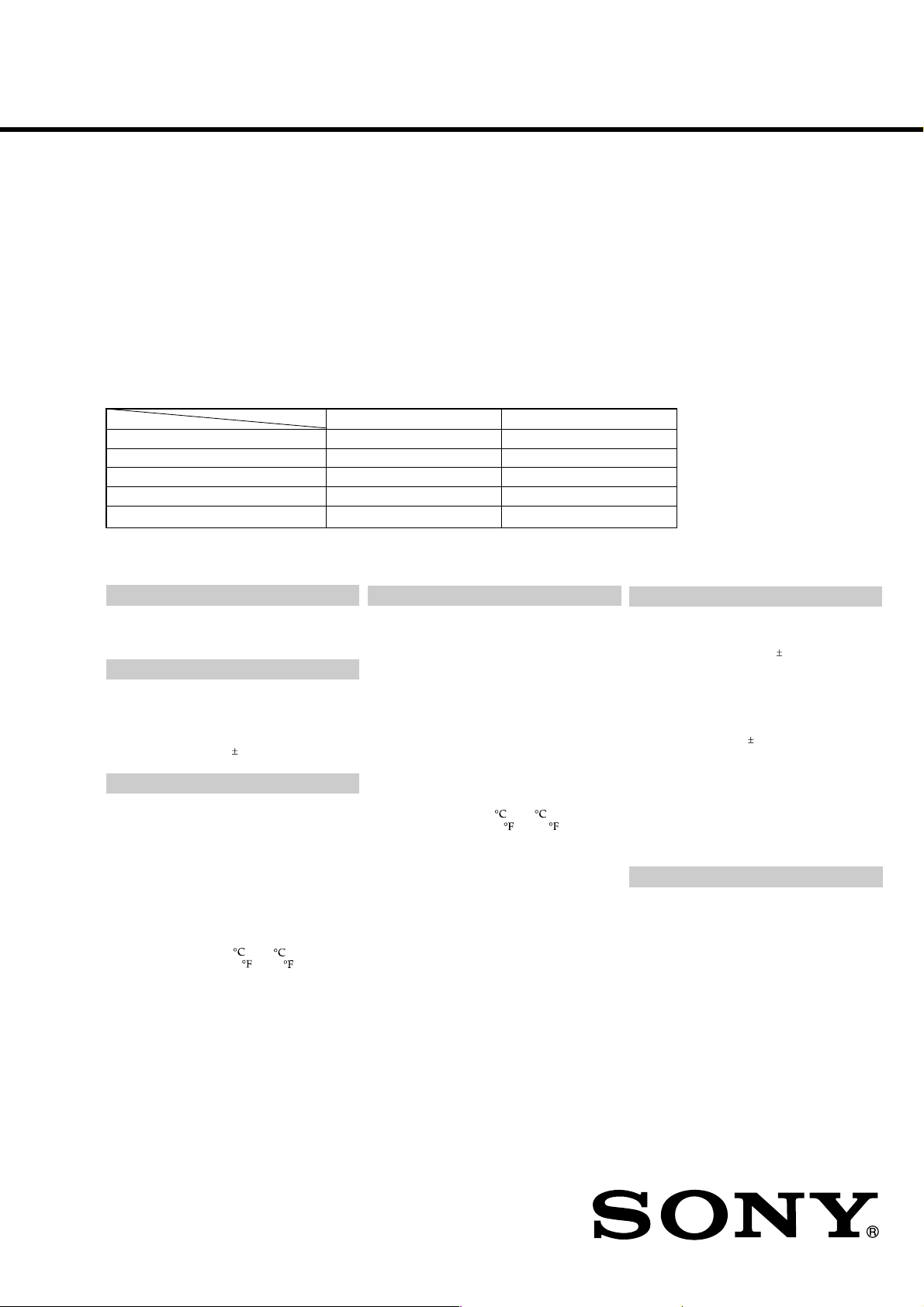
COMPONENT MODEL NAME
MODEL NUMBER LABEL PRINTED MODEL NAME
DVD PLAYER MV-7101DS MV-101
OVERHEAD MONITOR MV-7101DS XVM-R70
CONNECTION BOX – XA-115
CORDLESS STEREO HEADPHONE MDR-IF0140 MDR-IF0140
CARD REMOTE COMMANDER – RM-X135
SPECIFICATIONS
DVD player MV-101
System
Laser Semiconductor laser
Signal format system NTSC
Audio characteristics
Frequency response 20 Hz to 20 kHz
Signal to noise ratio 90dB (A)
Hermonic distortion 0.03 %
Dynamic range 90dB
Wow and flutter below measurable limits
( 0.001% W PEAK)
General
Outputs Audio output
Inputs IR input
Power requirements 12 V DC car battery
Dimensions Approx. 189 × 70 × 243 mm
Mass Approx. 2.1 kg
Operating temperature 0 to 45
Supplied accessories Parts for installation and
Video output
Optical output
DV 12V input
(negative ground)
1
/2 × 2 7/8 × 9 5/8 in)
(7
(w/h/d)
(4 lb 11 oz)
(32 to 113 )
connections (1 set)
Card remote commander
RM-X135
Operating Instructions (1 set)
Overhead Monitor XVM-R70
Monitor
System Liquid crystal color display
Display Manual flipdown panel
Drive system TFT-LCD active matrix
Picture size 7 inches wide screen (16:9)
Picture segment 336,960 (w 1440 × h 234)
Power requirements 12 V DC car battery
Current drain Approx. 800 mA
Dimensions 230 × 57 × 270 mm
Operating temperature 5 to 45
Mass Approx. 1.5 Kg (3 lb 5 oz)
Supplied accessories Connection box XA-115 (1)
system
154 × 87 mm, 176 mm
1
/
8
× 3 1/
2
(6
(w/h, d)
dots
(negative ground)
1
/
(9
(w/h/d)
(41 to 113 )
Monitor cable (5 m) (1)
Power supply cord (1)
DC-DC cord (3 m) (1)
Mounting plate (1)
Screws (4)
Tapping Screws (4)
in, 7 in)
8
× 2 3/8 × 10 3/4 in)
US Model
Connection box XA-115
A/V Output
Output Impedance: less than 220 Ω
Output Level: 0 dBs 3 dB
Video: 75 Ω 1Vp-p
A/V Input × 3
Input Impedance: more than 10 K Ω
Input Level: 1.3 dBs +0/-0.3 dB (0.775
Video: 75 Ω 1 Vp-p
DC output 7.5 V (max 2 A)
Dimensions 150 × 42 × 80 mm
Mass Approx. 260 g (9 oz)
Cordless Stereo headphone MDR-IF0140
General
Modulation system Frequency modulation
Carrier frequency
Frequency response
Power source DC 1.5 V (size AAA) dry
Mass Approx. 125 g (4.41 oz)
Design and specifications are subject to change
without notice.
less than 100 pF
(0.775 V rms)
(Vol Max)
less than 1000 pF
V rms)
11
/
16
× 3 1/
(6 ×
(w/h/d)
Right 2.8 MHz
Left 2.3 MHz
18 - 22,000 Hz
battery
including battery
4
in)
9-877-405-03 Sony Corporation
2004D05-1 e Vehicle Company
© 2004.04 Published by Sony Engineering Corporation
MOBILE VIDEO SYSTEM
MV-7101DS
Ver 1.1
NOTES ON HANDLING THE OPTICAL PICK-UP
BLOCK OR BASE UNIT
The laser diode in the optical pick-up block may suffer electrostatic break-down because of the potential difference generated
by the charged electrostatic load, etc. on clothing and the human
body.
During repair, pay attention to electrostatic break-down and also
use the procedure in the printed matter which is included in the
repair parts.
The flexible board is easily damaged and should be handled with
care.
NOTES ON LASER DIODE EMISSION CHECK
Never look into the laser diode emission from right above when
checking it for adjustment. It is feared that you will lose your sight.
CAUTION
Use of controls or adjustments or performance of procedures
other than those specified herein may result in hazardous radiation exposure.
Notes on chip component replacement
•Never reuse a disconnected chip component.
• Notice that the minus side of a tantalum capacitor may be damaged by heat.
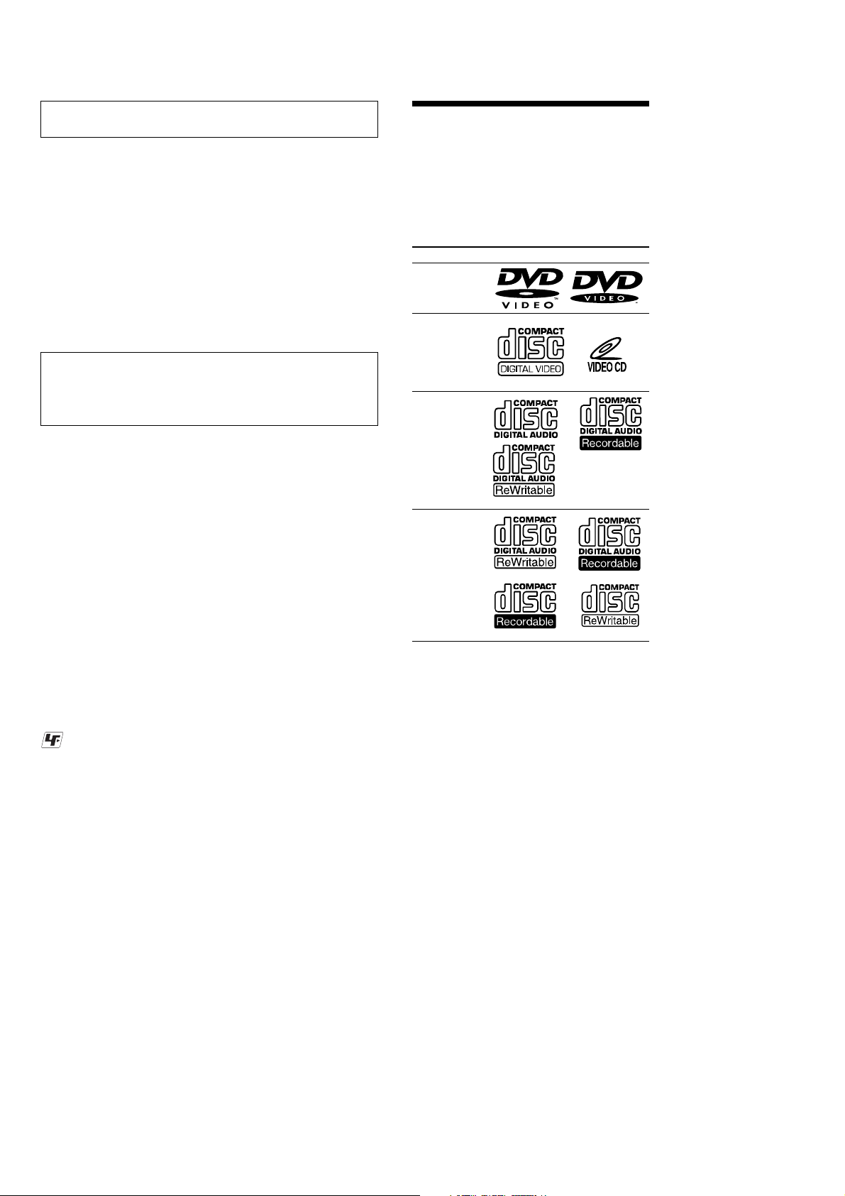
About discs this player can
play
This player can play 12 cm (4 7/10
•DVD
•Video CD
•Audio CD
•CD-R/CD-RW
Disc type Label on the disc
DVD Videos
Video CDs
Audio CDs
in) disc only.
Flexible Circuit Board Repairing
•Keep the temperature of the soldering iron around 270 ˚C during repairing.
• Do not touch the soldering iron on the same conductor of the
circuit board (within 3 times).
• Be careful not to apply force on the conductor when soldering
or unsoldering.
UNLEADED SOLDER
Boards requiring use of unleaded solder are printed with the leadfree mark (LF) indicating the solder contains no lead.
(Caution: Some printed circuit boards may not come printed with
the lead free mark due to their particular size)
: LEAD FREE MARK
Unleaded solder has the following characteristics.
• Unleaded solder melts at a temperature about 40 ˚C higher than
ordinary solder.
Ordinary soldering irons can be used but the iron tip has to be
applied to the solder joint for a slightly longer time.
Soldering irons using a temperature regulator should be set to
about 350 ˚C.
Caution: The printed pattern (copper foil) may peel away if the
heated tip is applied for too long, so be careful!
• Strong viscosity
Unleaded solder is more viscou-s (sticky, less prone to flow)
than ordinary solder so use caution not to let solder bridges occur such as on IC pins, etc.
• Usable with ordinary solder
It is best to use only unleaded solder but unleaded solder may
also be added to ordinary solder.
MP3 files
Notes on CD-Rs (recordable CDs)/
CD-RWs (rewritable CDs)
•Some CD-Rs/CD-RWs (depending on the
equipment used for its recording or the
condition of the disc) may not play on this
unit.
•You cannot play a CD-R/CD-RW that is not
finalized*.
•You can play MP3 files recorded on CDROMs, CD-Rs, and CD-RWs.
* A process necessary for a recorded CD-R/CD-RW
disc to be played on the audio CD player. Notes
on CD-Rs (recordable CDs)/CD-RWs (rewritable
CDs)
SAFETY-RELATED COMPONENT WARNING!!
COMPONENTS IDENTIFIED BY MARK 0 OR DOTTED
LINE WITH MARK 0 ON THE SCHEMATIC DIAGRAMS
AND IN THE PARTS LIST ARE CRITICAL TO SAFE
OPERATION. REPLACE THESE COMPONENTS WITH
SONY PARTS WHOSE PART NUMBERS APPEAR AS
SHOWN IN THIS MANU AL OR IN SUPPLEMENTS PUBLISHED BY SONY.
2

TABLE OF CONTENTS
1. GENERAL
Location of Controls ....................................................... 4
2. DISASSEMBLY
2-1. Disassembly Flow ........................................................... 11
2-2. Cabinet Front Assy.......................................................... 11
2-3. Cavity (Rear) ................................................................... 12
2-4. Case (Upper) ................................................................... 12
2-5. DVD MD Assy................................................................ 13
2-6. Chassis (MD) Assy ......................................................... 13
2-7. SERVO Board, Mechanism Deck................................... 14
2-8. TD-S-TOP-COVER ........................................................ 14
2-9. Loading Mechanism Assy............................................... 15
2-10. Traverse Mechanism Assy .............................................. 15
3. DIAGRAMS
3-1. Note for Printed Wiring Boards
and Schematic Diagrams ................................................ 17
3-2. Printed Wiring Boards – KEY Section – ....................... 18
3-3. Schematic Diagrams – KEY Section –.......................... 19
3-4. Printed Wiring Board – POWER Section –................... 20
3-5. Schematic Diagram – POWER Section – ..................... 21
MV-7101DS
Ver 1.1
4. EXPLODED VIEWS
4-1. Overall Section................................................................ 23
4-2. Cabinet Front Assy Section ............................................ 24
4-3. Case (Lower) Assy Section............................................. 25
4-4. DVD MD Assy Section................................................... 26
4-5. Mechanism Deck Section-1 ............................................ 27
4-6. Mechanism Deck Section-2 ............................................ 28
4-7. Mechanism Deck Section-3 ............................................ 29
5. ELECTRICAL PARTS LIST ............................... 30
3
MV-7101DS
Ver 1.1
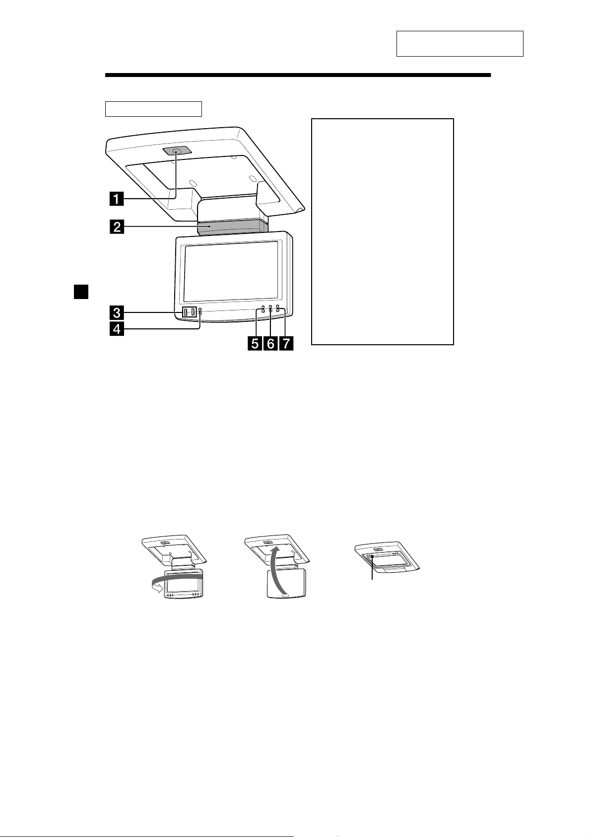
Location of controls
Monitor XVM-R70
SECTION 1
GENERAL
This section is extracted from
instruction manual.
Warning when installing in a
car without an ACC
(accessory) position on the
ignition key switch
To turn off the player and the
monitor, after you set the power
select switch to B (the setting
without ACC position) for your
(for details, refer to the installation/
car
connections manual)
There are 3 ways to turn off the
player and the monitor:
— After turning off the ignition, be
sure to press (POWER) on the
monitor.
— After turning off the ignition,
(MONITOR POWER) on the card
remote commander.
— After turning off the ignition, just
close the display panel until it
clicks.
Otherwise, the player and the
monitor do not turn off and this
causes battery drain.
1 OPEN button
To open the monitor.
2 Receptor for the card remote
commander/Transmitter for the
cordless headphones
3 UP/DOWN (M/m) buttons
To select the desired item.
4 MENU button
To adjust the various display settings.
* The reverse position of the display monitor.
You can close with the LCD surface out after turning around 180 degrees, and images on the screen
can be turned upside down by pressing (REVERSE) on the monitor. Before closing the display
monitor, make sure that the monitor is turned and facing the enclosure (you will hear a click). Each
time you press (REVERSE) on the monitor, the reverse screen mode switches between on and off.
180ß
c c
5 REVERSE button*
To switch images upside down.
6 INPUT button
To select the input source.
7 POWER button
To turn on/off the player and the
monitor.
REVERSE
4

Card remote commander RM-X135
MV-7101DS
Ver 1.1
ENTER
INPUT
POWER
SEARCH
CLEAR
SUBTITLE
ANGLE
AUDIO
SETUP
MONITOR
POWER
DISPLAY
123
456
7 890
TOP MENU
MENU
VOL
Refer to the pages listed for details.
1 DISPLAY button
To display a running time.
2 Number buttons
3 TOP MENU button
To display the top menu of a recorded
DVD or to turn on/off the PBC (Playback
control) menu of a Video CD.
4 MENU button
To display the recorded DVD menu.
5 O (return) button
6 ./> (previous/next) buttons
7
/m (fast/slow reverse)/
M/y (fast/slow forward) buttons
8 M/,/m/< buttons
9 POWER (on/off) button
To turn on/off the player. For details, refer
to the POWER (on/off) button (1) on the
player
q; SEARCH button
To specify a desired point on a disc by
chapter, title, or track.
qa CLEAR button
qs SUBTITLE button
To change the subtitle language while
playing a DVD
The corresponding buttons of the card
remote commander control the same
functions as those on the player and
the monitor.
Instructions in this manual describe how to use
the player and the monitor by mainly using the
card remote commander.
Tip
Refer to “Replacing the lithium battery of the card
remote commander” for details on how to replace
the battery.
Cautions about the POWER (on/off) button (9)
The POWER (on/off) button (9) is only for the
player. If you want to turn off the player and the
monitor completely, press the MONITOR POWER
(ql).
Cautions about the MONITOR POWER (on/off)
button (ql)
• To turn off the player and the monitor, press the
MONITOR POWER button (ql) or press the
POWER button (7) on the monitor or
display panel of the monitor until it
• To turn on the player and the monitor again, be
sure to press the POWER button (7) on the
monitor.
close the
clicks.
qd ENTER button
To enter a setting.
qf ANGLE button
To select the multiple angles of view while
playing or pausing a DVD.
qg AUDIO button
To change the audio output/audio
language
qh SETUP buttons
To enter or quit the setup menu.
qj u (play/pause) button
qk x (stop) button
ql MONITOR POWER (on/off) button*
To turn on/off the player and the monitor.
w; INPUT button*
To select the input source.
wa VOL (–/+) buttons*
To turn up or down the volume.
* For the monitor XVM-R70.
These buttons also work for optional Sony
monitors other than XVM-R75 and XVM-H6.
5

MV-7101DS
Ver 1.1
DVD player MV-101
POWER
POWER
Refer to the pages listed for details.
1 POWER (on/off) button
The player doesn't turn on, when the
monitor is turned off. Turn on the
monitor first.
To turn on/off the player, press and hold
the POWER button until the green light of
the button is turned on/off.
2 DISC IN light
When a disc is in the player, the DISC IN
light glows orange.
3 Receptor for the card remote
commander
4 u (play/pause) button
5 x (stop) button
6 Disc slot
7 Z (eject) button
Available to eject a disc from the player
even when the player is turned off.
8 RESET button
9 > (next) button
q; . (previous) button
DISC IN
MV-101
DISC IN
RESET
MV-101
Cautions
The player doesn't turn on, when the monitor
is turned off.
•To turn on the player, press (POWER) on
the monitor or (MONITOR POWER) on the
card remote commander. The player turns
on in conjunction with the monitor.
•If the player does not turn on in conjunction
with the monitor, press (POWER) on the
remote commander or on the player until the
green light of the POWER button (1)
on the player lights up.
Note
Even when the player is turned off, you can eject a
disc from the player, though you cannot insert a
disc.
6

Cordless Stereo Headphone
MDR-IF0140
N
E
P
O
1 Battery compartment lid
To set a battery, open the lid.
2 Ear pad
The ear pads are replaceable.
3 Power (ON/OFF) switch 17
4 POWER indicator
When the power switch of the headphones
is set to ON, the POWER indicator lights
up in red.
5 VOL control dial
To adjust the volume level from 0 to 10.
O
N
O
FF
POW
ER
VOL
When to replace the battery
When the battery becomes weak, the power
indicator light dims, or sound becomes
distorted or noisy. Replace the battery with
new one as soon as possible.
Inserting the battery
1
Open the lid (Z OPEN) of the left
housing.
Lid (Z OPEN)
2
Insert the size AAA dry battery into the
battery compartment matching
terminal on the battery to 3 on the
compartment.
AAA dry
battery
3
MV-7101DS
Ver 1.1
Battery life
Size AAA dry battery (1) is supplied with the
headphone.
Battery Approx. hours*
Sony alkaline battery 60 hours*
LR03/AM-4 (N)
Sony manganese battery 28 hours*
R03/UM-4 (NU)
1
*
at 1 kHz, 1 mW+1 mW output
2
Time stated above may vary, depending on the
*
temperature or conditions of use.
Notes on Battery
• Do not charge the dry battery.
• Do not carry the dry battery together with coins
or other metallic objects. It can generate heat if
the positive and negative terminals of the
battery are accidentally come into contact with
metallic objects.
• When you are not going to use the headphones
for a long time, remove the battery to avoid
damage from battery leakage or corrosion.
2
2
3
Close the lid (Z OPEN).
1
Lid (Z OPEN)
7

MV-7101DS
Parts list (1)
The numbers in the list are keyed to those in the
instructions.
Cautions on installation of the
monitor XVM-R70
• Installing the monitor
requires technical
expertise.
The monitor should be
installed by a qualified
technician or service
personnel.
• If you try to install the
monitor by yourself, do
it properly, referring to
the installation and
connection diagrams in
this installation/
connection manual.
Improper installation
may result in fire or
electric shock.
• Before installation, be
sure to turn the ignition
key switch to the OFF
position or take the key
out. Installing the
monitor with the
ignition key switch ON
may cause battery drain
or a short circuit.
• Do not damage any
pipes, tubes, the fuel
tank or electric wiring
when installing the
monitor. This can cause
a fire. If you drill a hole
in car panels, make sure
that any hidden car
parts will not be
damaged.
• Do not use any nuts or
bolts for safety devices
such as steering linkage,
fuel supply or braking
systems. This can cause
a fire or an accident.
• Take care to prevent
cords and wires from
getting tangled or
crimped in the moving
portion of a seat rail.
x
How to install the monitor
XVM-R70 (2)
Caution
Installing the monitor requires technical
expertise. The monitor should be installed by
a qualified technician or service personnel.
Where to install
Before installing the monitor, please check your
local traffic rules and regulations. Follow the
diagram below to install the monitor in a suitable
position in your car.
Do not install the monitor where:
— It will obstruct the driver’s view when the
monitor is in either the open or closed position.
— It will obstruct the operation of the airbag
system.
— It will obstruct the operation of the vehicle,
especially the steering wheel, shift lever, or
brake pedal.
— A driver or passengers may injure themselves
when getting into or out of the car.
If you have any questions or problems
concerning your unit that are not covered in this
manual, please consult your nearest Sony
dealer.
How to set the power select
switch on the monitor XVM-R70
(3)
Before installing
Make sure that the POWER SELECT switch is set to
the correct position.
A*: if your car has ACC (accessory) position on the
ignition key switch.
B : if your car has no ACC (accessory) position on
the ignition key switch.
* A is the factory preset position.
Warning when installing in a car
without ACC (accessory)
position on the ignition key
switch
To turn on the player and the monitor,
after you set the power select switch to B
(the setting without ACC position) for your
car
Press (POWER) on the monitor*.
* You cannot turn on the player and the monitor by
pressing (POWER) or (MONITOR POWER) on the card
remote commander.
To turn off the player and the monitor,
after you set the power select switch to B
(the setting without ACC position) for your
car
There are 3 ways to turn off the player and the
monitor:
— After turning off the ignition, be sure to press
(POWER) on the monitor.
— After turning off the ignition,
(MONITOR POWER) on the card remote
commander
— After turning off the ignition, just close the
display panel of the monitor until it clicks.
8
4
MV-7101DS
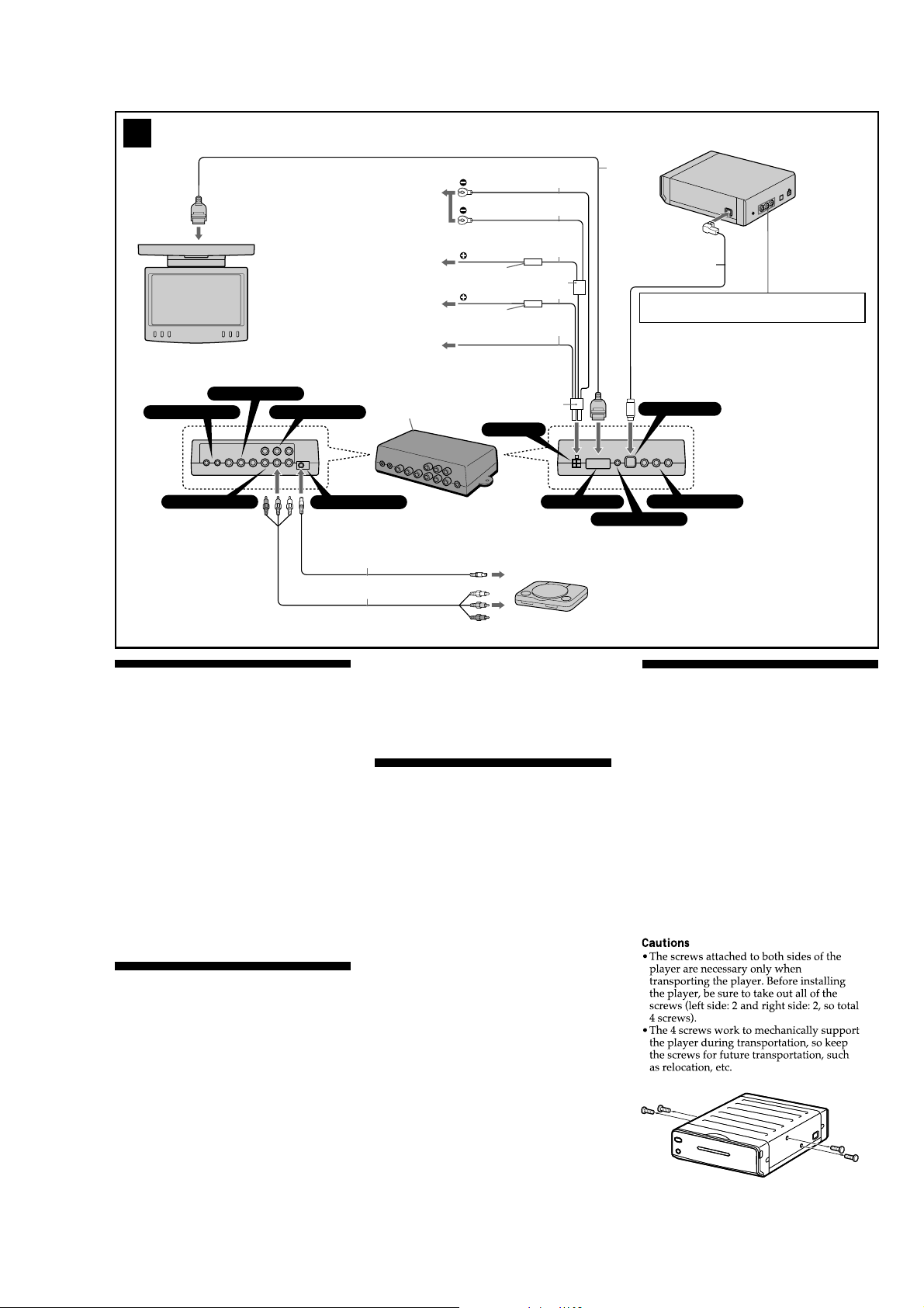
XVM-R70
HEAD PHONE
V/L/R VIDEO 3
V/L/R VIDEO 1
Max. supply current 0.3 A
V/L/R VIDEO 2
RCA pin cord (optional)
DC OUT
GND 1 m
(3.3 ft (pi))
1
GND 1 m
(3.3 ft (pi))
5 m
(16.4 ft (pi))
2
Fuse (8 A)
ACC (5 m)
(16.4 ft (pi))
3
Fuse (1 A)
POWER REM 5 m (16.4 ft (pi))
4
4
POWER
XA-115
3
black
black
yellow
Filter box
red
blue/white striped
1
MONITOR OUT
2
REMOTE SIGNAL
PS One (optional)
MV-101
8
Do not use the R (audio right)/L (audio left)/V (video)
output on the rear of the player.
DVD IN
V/L/R VIDEO OUT
Cautions before connection
• The products are designed for negative ground 12 V
DC operation only.
• Before making connections, turn the car ignition off to
avoid short circuits.
• Connect the yellow and red power input leads only
after all other leads have been connected.
• Be sure to connect the red power input lead to the
positive 12 V power terminal which is powered when
the ignition switch is in the accessory position.
• Run all ground wires to a common ground point.
• The use of optical instruments with the player will
increase eye hazard.
• Use of controls adjustments or performance of
procedures of other than those specified herein may
result in hazardous radiation exposure.
Notes on the power supply cord (yellow)
•When connecting the player and the monitor in
combination with other stereo components, the
connected car circuit’s rating must be higher than the
sum of each component’s fuse.
•When no car circuits are rated high enough, connect
the products directly to the battery.
Connection diagram (4)
1 To a metal surface on the car
First connect the black ground lead, then
connect the yellow and red power input leads.
2 To the +12 V power terminal which is
powered at all times
Be sure to connect the black ground lead to a
metal surface of the car first.
3 To the +12 V power terminal which is
powered when the ignition switch is in
the accessory position
Be sure to connect the black ground lead to a
metal surface of the car first.
Caution
If your car has no accessory position on the
ignition key, be sure to insulate and do not
connect the ACC lead (red) to anywhere. If you
connect the ACC lead according to the Operating
Instructions, it will cause the battery drain.
4 To POWER REMOTE IN of an optional
power amplifier
This connection is for amplifiers.
Notes
• If there is no accessory position, connect to the +12
V power (battery) terminal which is energized at
all times. Be sure to connect the black ground lead
to a metal surface of the car first.
• If you use the R (audio right)/L (audio left)/V
(video) output on the rear of the player, the
output level of video will be halved.
Cautions on installation of the
player MV-101
• Choose the mounting location carefully.
• Avoid installing the player in places:
— subject to temperatures below – 30 °C (– 22 °F) or
above 45 °C (113 °F)
— subject to direct sunlight.
— subject to heat;
Keep all products away from nearby hot vehicle
components that heat up over time such as hoses,
high current wires, and braking system
components. Make sure to leave enough room for
ventilation of openings and slots to protect from
over heating.
— near heat sources such as heaters.
— exposed to rain or moisture.
— exposed to excessive dust or dirt.
— subject to excessive vibration.
— where the fuel tank might be damaged by the
tapping screws.
— where wire harnesses or pipes might be under the
place.
— where the screws or the player itself might damage
the spare tire, tools, or other equipment in or
under the trunk.
— where the player might interfere with with the
normal movements of the driver.
— under the floor carpet, as the heat dissipation from
the player might damage the carpet.
• Be sure to use only the supplied mounting hardware
for a safe and secure installation.
• Use only the supplied screws.
• Make holes of ø 3 mm (
there is nothing on the other side of the mounting
surface.
• Do not install the player on inclined places. Install the
player on a level surface.
• Install the player just horizontally or vertically.
1
/8 in) only after making sure
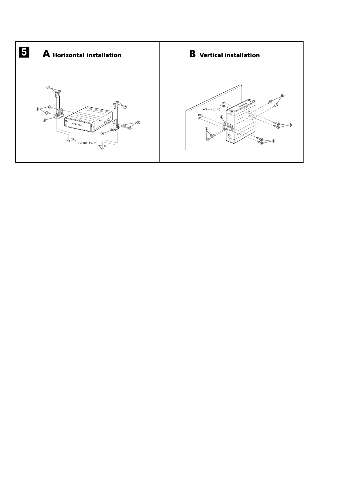
How to install the player
MV-101 (5)
When installing the player, choose the mounting
location carefully.
1
Place the player where you plan to install
it.
2
Mark the 4 positions for the holes of the
screws
7
board (not supplied).
The supplied mounting screws 7 are 15 mm
19
(
board is thicker than 15 mm (
3
Drill the 4 positions to make the holes of ø
3 mm (
4
Mount the player on the board (not
supplied) with the parts
screws of
on the surface of the mounting
/32 in) long, so make sure that the mounting
1
/
32
in) in diameter.
6
and 7.
19
/32 in).
5
and mounting
9
MV-7101DS
10

• This set can be disassembled in the order shown below.
2-1. DISASSEMBLY FLOW
SET
SECTION 2
DISASSEMBLY
Note 1: The process described in can be performed in any order.
Note 2: Without completing the process described in ,
the next process can not be performed.
MV-7101DS
Ver 1.1
2-2. CABINET FRONT ASSY
(Page 11)
2-4. CASE (UPPER)
(Page 12)
2-5. DVD MD ASSY
(Page 13)
2-6. CHASSIS (MD) ASSY
(Page 13)
2-7. SERVO BOARD, MECHANISM DECK
(Page 14)
2-8. TD-S-TOP-COVER
(Page 14)
2-9. LOADING MECHANISM ASSY
(Page 15)
2-10. TRAVERSE MECHANISM ASSY
(Page 15)
2-3. CAVITY (REAR)
(Page 12)
Note: Follow the disassembly procedure in the numerical order given.
2-2. CABINET FRONT ASSY
6
key flexible board
(CN102)
4
two claws
3
screw
(+B2.6 × 6)
5
1
two screws
(+K2.6 × 6)
2
screw
(+B2.6 × 6)
8
cabinet front assy
7
connector (CN101)
11
 Loading...