

Sony MV-700-HR Service manual
MV-700HR
System
Laser Semiconductor laser
Signal format system PAL/NTSC
Audio characteristics
Frequency response 20 Hz to 20 kHz
Signal to noise ratio 90 dB (A)
Harmonic distortion 0.03%
Dynamic range 90 dB
Wow and flutter below measurable limits
(±0.001% W PEAK)
General
Outputs Audio/video output
Headphones output
Optical output
Inputs Audio/video input
DC 12V input
Power requirements 12 V DC
Dimensions Approx. 220 × 44 × 152 mm
(w/h/d)
Mass Approx. 1.2 kg
Operating temperature 0˚C to 45˚C
Supplied accessories AC power adaptor (1)
(including AC power cords
(2) (AEP, UK), (1) (except
Power cord for the cigar
AEP, UK))
lighter socket (1)
Card remote commander
RM-X707 (1)
Headrest installation kit (1)
Installation cradle (1)
Lithium battery for
memory back-up CR2032
(1)
Carrying bag (1)
Operating Instructions (1)
Monitor
System Liquid crystal color display
Display Manual flipdown panel
Drive system TFT-LCD active matrix
system
Picture size 7 inches wide screen (16:9)
Picture segment 336,960 (w 1440 × h 234)
dots
Radio section
Tuning range FM: 87.5 - 108.0 MHz
US, CND, E (PAL), TW,
KR, AUS, CH
Intermediate frequency 225 kHz
Usable sensitivity 20 dBf
Frequency response 30 - 15,000 Hz
S/N ratio 66 dB (stereo)
66 dB (mono)
Harmonic distortion at 1 kHz
0.8% (stereo)
0.8% (mono)
Separation 30 dB at 1 kHz
Audio/video cable (1)
(except AEP, UK, RU)
(US, CND, E (NTSC))
(US, CND, E (PAL), TW,
(E (PAL), TW, KR, AUS, CH)
(E (PAL), TW, KR, AUS, CH)
KR, AUS, CH)
FM antenna (1)
Rechargeable battery (1)
Power cable (1)
Connection box XA-121
SERVICE MANUAL
Ver. 1.2 2005.08
Copyrights
This product incorporates copyright protection
technology that is protected by method claims
of certain U.S. patents, other intellectual
property rights owned by Macrovision
Corporation, and other rights owners. Use of
this copyright protection technology must be
authorized by Macrovision Corporation, and is
intended for home and other limited viewing
uses only unless otherwise authorized by
Macrovision Corporation. Reverse engineering
or disassembly is prohibited.
•“Memory Stick,”
Memory Stick” are trademarks of Sony
Corporation.
•“Memory Stick Duo” and “
are trademarks of Sony Corporation.
•“MagicGate” and “
trademarks of Sony Corporation.
•“Memory Stick PRO” and “ ”
are trademarks of Sony Corporation.
Manufactured under license from Dolby
Laboratories. “Dolby”, “Pro Logic”, and the
double-D symbol are trademarks of Dolby
Laboratories.
“DTS,” “DTS Digital Surround” and “DTS
Digital Out” are trademarks of Digital Theater
Systems, Inc.
DivX is a registered trademark of
DivXNetworks, Inc.
and “MagicGate
” are
US Model
Canadian Model
AEP Model
UK Model
E Model
Austr alian Model
Chinese Model
Model Name Using Similar Mechanism NEW
Optical Pick-up Block Name SDR-085T
SPECIFICATIONS
”
PORTABLE DVD PLAYER
– Continued on next page –
9-879-661-03
2005H05-1
© 2005.08
Sony Corporation
e Vehicle Group
Published by Sony Engineering Corporation
MV-700HR
Ver. 1.2
On power sources
•Use house current or a car battery (12 V DC).
•For use in your house, use the AC power
adaptor supplied with the player. Do not use
any other AC power adaptor since it may
cause the player to malfunction.
Polarity of
the plug
Design and specifications are subject to change
without notice.
• Abbreviation
AUS: Australian model
CH : Chinese model
CND: Canadian model
KR : Korean model
TW : Taiwan model
CAUTION
The use of optical instruments with this
product will increase eye hazard.
CAUTION
Use of controls or adjustments or performance of procedures
other than those specified herein may result in hazardous radiation
exposure.
Notes on chip component replacement
• Never reuse a disconnected chip component.
• Notice that the minus side of a tantalum capacitor may be
damaged by heat.
Flexible Circuit Board Repairing
• Keep the temperature of the soldering iron around 270 ˚C
during repairing.
• Do not touch the soldering iron on the same conductor of the
circuit board (within 3 times).
• Be careful not to apply force on the conductor when soldering
or unsoldering.
CAUTION
Danger of explosion if battery is incorrectly replaced.
Replace only with the same or equivalent type recommended by
the manufacturer.
Discard used batteries according to the manufacturer’s instructions.
ADVARSEL!
Lithiumbatteri-Eksplosionsfare ved fejlagtig håndtering.
Udskiftning må kun ske med batteri
af samme fabrikat og type.
Levér det brugte batteri tilbage til leverandøren.
ADVARSEL
Eksplosjonsfare ved feilaktig skifte av batteri.
Benytt samme batteritype eller en tilsvarende type
anbefalt av apparatfabrikanten.
Brukte batterier kasseres i henhold til fabrikantens
instruksjoner.
VARNING
Explosionsfara vid felaktigt batteribyte.
Använd samma batterityp eller en likvärdig typ som
rekommenderas av apparattillverkaren.
Kassera använt batteri enligt gällande föreskrifter.
This label is located on the bottom of the
chassis.
CAUTION
RADIATION WHEN OPEN AND INTERLOCKS DEFEATED.
DO NOT VIEW DIRECTLY WITH OPTICAL INSTRUMENTS.
:CLASS 1M VISIBLE/INVISIBLE LASER
This label is located on the drive unit's internal
chassis
SAFETY-RELATED COMPONENT WARNING!!
COMPONENTS IDENTIFIED BY MARK 0 OR DOTTED LINE
WITH MARK 0 ON THE SCHEMATIC DIAGRAMS AND IN
THE PARTS LIST ARE CRITICAL TO SAFE OPERATION.
REPLACE THESE COMPONENTS WITH SONY PARTS WHOSE
PART NUMBERS APPEAR AS SHOWN IN THIS MANUAL OR
IN SUPPLEMENTS PUBLISHED BY SONY.
VAROITUS
Paristo voi räjähtää, jos se on virheellisesti asennettu.
Vaihda paristo ainoastaan laitevalmistajan suosittelemaan tyyppiin.
Hävitä käytetty paristo valmistajan ohjeiden mukaisesti.
ATTENTION AU COMPOSANT AYANT RAPPORT
À LA SÉCURITÉ!
LES COMPOSANTS IDENTIFIÉS P AR UNE MARQUE 0 SUR
LES DIAGRAMMES SCHÉMATIQUES ET LA LISTE DES
PIÈCES SONT CRITIQUES POUR LA SÉCURITÉ DE
FONCTIONNEMENT. NE REMPLACER CES COM- POSANTS
QUE PAR DES PIÈCES SONY DONT LES NUMÉROS SONT
DONNÉS DANS CE MANUEL OU D ANS LES SUPPLÉMENTS
PUBLIÉS PAR SONY.
2

TABLE OF CONTENTS
1. SERVICING NOTES ................................................ 4
2. GENERAL
Location of Controls........................................................ 6
3. DISASSEMBLY
3-1. Disassembly Flow ........................................................... 9
3-2. Cover (Hinge) .................................................................. 10
3-3. Front/Rear Case (Main) Section, Monitor Section.......... 10
3-4. Optical Pick-up Block (SDR-085T)................................ 11
3-5. Memory Stick Connector, MAIN Board ......................... 11
3-6. Rear Case (LCD) Section................................................ 12
3-7. MONITOR Boar d............................................................ 12
3-8. Liquid Crystal Display Panel (LCD900)......................... 13
4. TEST MODE.............................................................. 14
5. ELECTRICAL ADJUSTMENTS ......................... 15
6. DIAGRAMS
6-1. Block Diagram – DVD Section – .................................... 19
6-2. Block Diagram – AUDIO Section –................................ 20
6-3. Block Diagram – VIDEO Section – ................................ 21
6-4. Block Diagram – POWER SUPPLY Section – ............... 22
6-5. Printed Wiring Board – MAIN Section (1/2) – ............... 24
6-6. Printed Wiring Board – MAIN Section (2/2) – ............... 25
6-7. Schematic Diagram – MAIN Section (1/4) –.................. 26
6-8. Schematic Diagram – MAIN Section (2/4) –.................. 27
6-9. Schematic Diagram – MAIN Section (3/4) –.................. 28
6-10. Schematic Diagram – MAIN Section (4/4) – .................. 29
6-11. Printed Wiring Board – MONITOR Section (1/2) – ....... 30
6-12. Printed Wiring Boards – MONITOR Section (2/2) –...... 31
6-13. Schematic Diagram – MONITOR Section (1/4) – .......... 32
6-14. Schematic Diagram – MONITOR Section (2/4) – .......... 33
6-15. Schematic Diagram – MONITOR Section (3/4) – .......... 34
6-16. Schematic Diagram – MONITOR Section (4/4) – .......... 35
MV-700HR
7. EXPLODED VIEWS
7-1. Overall Section................................................................ 54
7-2. Rear Case (LCD) Section................................................ 55
7-3. Front Case (LCD) Section............................................... 56
7-4. Front Case (Main) Section .............................................. 57
7-5. Rear Case (Main) Section................................................ 58
7-6. Connection Box Section (XA-121) ................................. 59
8. ELECTRICAL PARTS LIST................................ 60
3
MV-700HR
Ver. 1.2
SECTION 1
SERVICING NOTES
NOTES ON HANDLING THE OPTICAL PICK-UP
BLOCK OR BASE UNIT
The laser diode in the optical pick-up block may suffer electrostatic
break-down because of the potential difference generated by the
charged electrostatic load, etc. on clothing and the human body.
During repair, pay attention to electrostatic break-down and also
use the procedure in the printed matter which is included in the
repair parts.
The flexible board is easily damaged and should be handled with
care.
NOTES ON LASER DIODE EMISSION CHECK
Never look into the laser diode emission from right above when
checking it for adjustment. It is feared that you will lose your sight.
UNLEADED SOLDER
Boards requiring use of unleaded solder are printed with the leadfree mark (LF) indicating the solder contains no lead.
(Caution: Some printed circuit boards may not come printed with
the lead free mark due to their particular size)
: LEAD FREE MARK
Unleaded solder has the following characteristics.
• Unleaded solder melts at a temperature about 40 ˚C higher
than ordinary solder.
Ordinary soldering irons can be used but the iron tip has to be
applied to the solder joint for a slightly longer time.
Soldering irons using a temperature regulator should be set to
about 350 ˚C.
Caution: The printed pattern (copper foil) may peel away if
the heated tip is applied for too long, so be careful!
• Strong viscosity
Unleaded solder is more viscou-s (sticky, less prone to flow)
than ordinary solder so use caution not to let solder bridges
occur such as on IC pins, etc.
• Usable with ordinary solder
It is best to use only unleaded solder but unleaded solder may
also be added to ordinary solder.
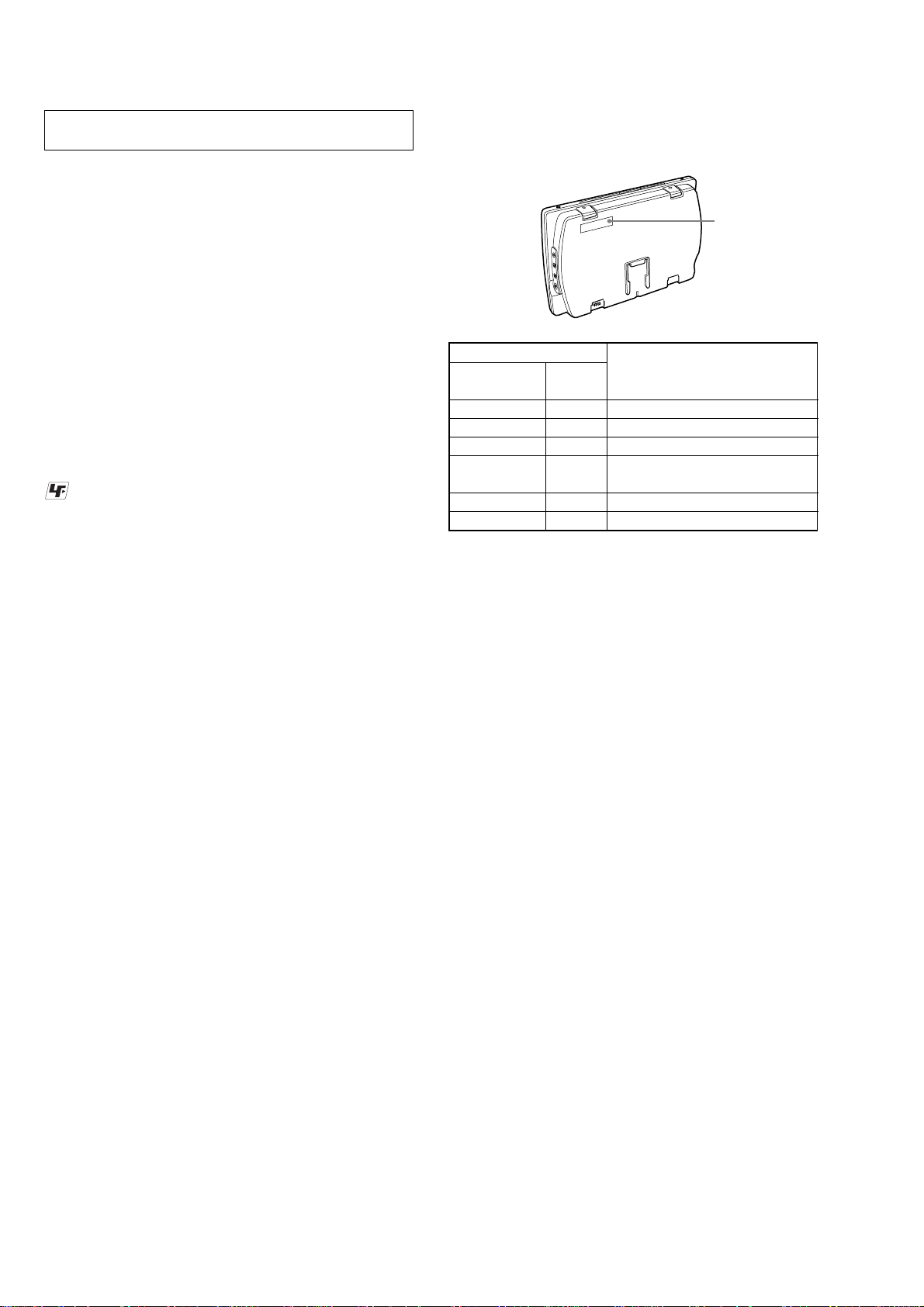
MODEL IDENTIFICATION
– Bottom View –
Region code label
Label indication
Signal format Region Destination
system code
NTSC 1 US, Canadian models
PAL2AEP, UK models
PAL5Russian model
PAL 3
NTSC 4 E (NTSC) model
PAL6Chinese model
NOTE FOR REPLACING THE MAIN BOARD OR
IC105 ON THE MAIN BOARD
This set requires writing the region code for each destination, if the
MAIN board or IC105 was replaced. Therefore, be sure perform
the region code writing as below.
1. Download the software for region code from website of the
ESI and write this software to a CD-R.
2. Set the CD-R to the set and load the software.
E (P AL), Taiwan, Korean,
Australian models
4
About the discs this player
can play
This player can play the following discs:
•DVD Video
•DVD-R/DVD+R
•DVD-RW/DVD+RW
•Video CD
•Audio CD
•CD-R/CD-RW
Format of discs
DVD VIDEO
DVD-R*
DVD-RW*
DVD+R*
DVD+RW*
Notes on CD-Rs (recordable CDs)/
CD-RWs (rewritable CDs)/DVD-Rs
(recordable DVDs)/DVD+Rs/DVDRWs (rewritable DVDs)/DVD+RWs
•Some CD-Rs/CD-RWs/DVD-Rs/DVD+Rs/
DVD-RWs/DVD+RWs (depending on the
equipment used for its recording or the
condition of the disc) may not play on this
player.
•You cannot play a CD-R/CD-RW that is not
finalized*.
•You can play MP3/JPEG/DivX files recorded
on CD-ROMs, CD-Rs, CD-RWs, DVD-Rs,
DVD+Rs, DVD-RWs and DVD+RWs.
* A process necessary for a recorded CD-R/CD-RW
disc to be played on the CD player.
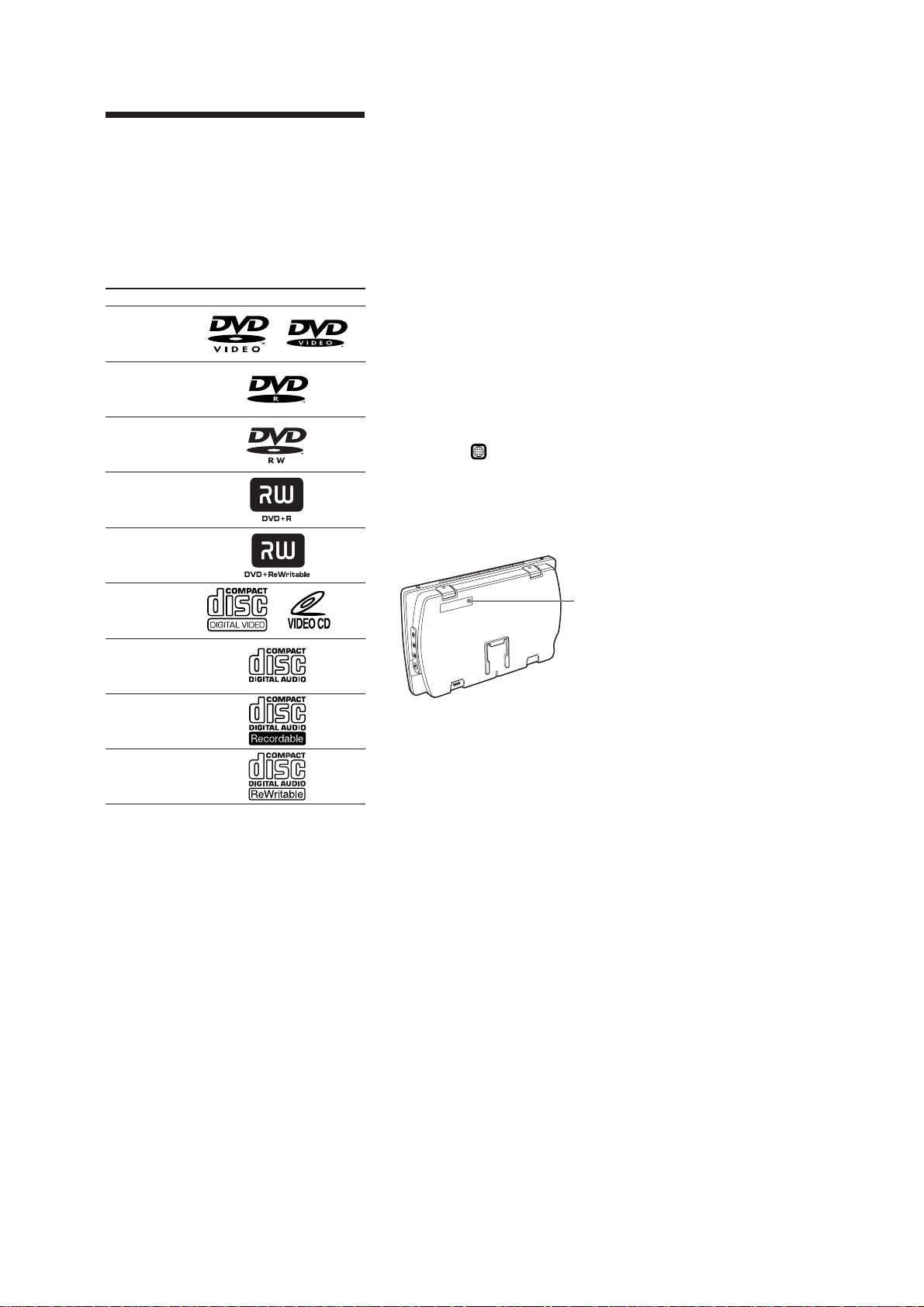
Region code of DVDs this player
can play
This player has a region code printed on the
bottom of the player and will only play DVDs
that are labeled with identical region codes.
DVDs labeled
player.
If you try to play any other DVD, the message
“Wrong Region” will appear on the screen.
Depending on the DVD, the region code
indication may not appear even if the DVD is
prohibited by area restrictions.
will also be played on this
ALL
MV-700HR
Video CD
Audio CD
CD-R*
CD-RW*
* Including MP3/JPEG/DivX® files.
“DVD VIDEO,” “DVD-R,” “DVD-RW,”
“DVD+R,” and “DVD+RW” are trademarks.
Region
code
5
MV-700HR
SECTION 2
GENERAL
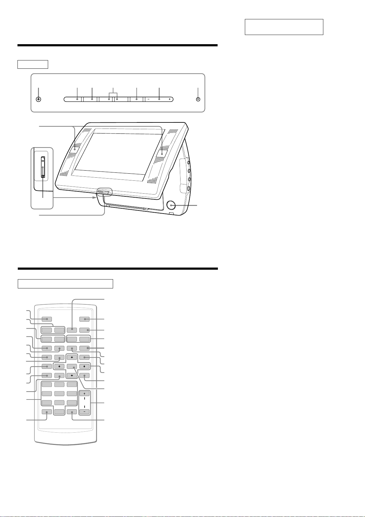
Location of controls
MV-700HR
1 2 3 4 5 6 7
POWER SOURCE
ux >
>
8
S-MENU VOLUME
This section is extracted from
instruction manual.
1 POWER (on/off) button
To turn on/off the monitor.
2 u (play/pause) button
3 x (stop) button
4 . (previous)/> (next) buttons
5 S-MENU button
To make various display settings.
6 VOLUME–/+ buttons
To turn up or down the volume or to select
the item during menu operation.
7 SOURCE button
To select the input source.
8 Receptor for the card remote
commander/Transmitter for the cordless
headphones
9 “Memory Stick” slot
0 Release lever
qa PUSH OPEN
9
0
Card remote commander RM-X707
1
2
3
4
5
6
7
8
9
0
qa
qs
SOURCE
Mm
AUDIO
SUBTITLE
SETUP
TOP MENU
CLOCK
SEARCHOPROGRAM
1
2
4
5
7
8
CLEAR DSPL
0
ANGLE
ENTER
3
6
9
`/1
ux>.
y
y
REP
MENU
VOL
qd
qf
qg
qh
qj
qk
ql
w;
wa
ws
wd
wf
qa
The corresponding buttons of the card
remote commander control the same
functions as those on the player.
Instructions in this manual describe how to use
the player by mainly using the card remote
commander.
Tip
Refer to “Replacing the lithium battery of the card
remote commander” for details on how to replace
the battery.
1 SOURCE button
To select the input source.
2 ./> (previous/next) buttons
3 m (fast reverse)/M (fast forward)
buttons
4 AUDIO button
To change the audio output/audio
language.
5 SUBTITLE button
To change the subtitle language while
playing a DVD.
6 SETUP button
Used to perform menu operations.
7 TOP MENU button
To display the top menu of a recorded
DVD.
8 CLOCK button
To display the calendar or clock.
9 SEARCH button
To specify a desired point on a disc by
chapter, title or track.
0 PROGRAM button
To enter the program Playback Mode.
qa Number buttons
qs CLEAR button
qd x (stop) button
qf [/1 (power on/off) button
qg u (play/pause) button
qh t (slow reverse)/T (slow forward)
buttons
qj REP button
To select the repeat mode (DVD/Video
CD/Audio CD), or playback mode (MP3/
JPEG/DivX).
qk ANGLE button
To select the multiple angles of view while
playing a DVD.
ql MENU button
To display the recorded DVD menu.
w; M/m/</, buttons
wa O (return) button
ws ENTER button
To enter a setting.
wd VOL (+/–) buttons
wf DSPL button
To display the time information of the disc.
6
MV-700HR
Ver. 1.2
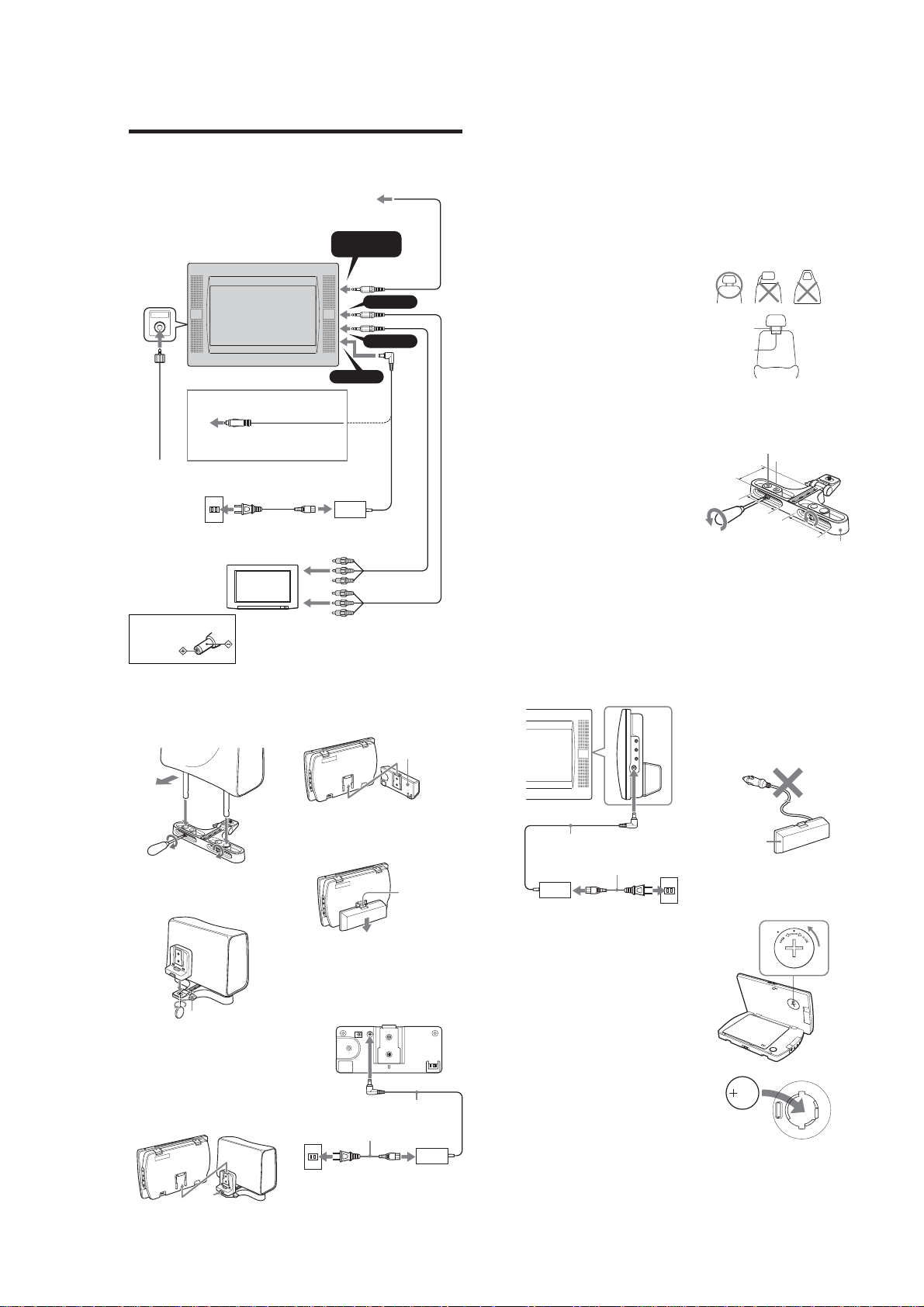
US, Canadian, E (PAL), Taiwan, Korean, Australian, Chinese models
On A/V OUTPUT connectors
Connection
This player is supplied in two kinds of connection method. When using at home, connect it to the
AC outlet. When using in a car, connect the player using the supplied cigar lighter adapter.
When using the AC power supply
EXT ANT
To the cigar
lighter socket
Cigar lighter adapter
(supplied)
FM antenna
(supplied)
To a wall outlet
AC power cord
(supplied)
When using the
player in the car
To audio/video
input connectors
To a digital
amplifier, etc.
HEADPHONES/
OPTICAL OUT
DC IN 12V
Optical cable
(not supplied)
OUTPUT
A/V OUTPUT
A/V INPUT
*
AC power
adaptor
(supplied)
You can connect a TV to the A/V OUTPUT
connectors to output the contents being played
back on the player. Connect the yellow plugs
of the audio/video cable to the video
connectors on both the TV and the player, and
connect the white plugs to the white (left
audio) connectors and the red plugs to the red
(right audio) connectors respectively.
On A/V INPUT connectors
You can connect a VTR, etc. to the A/V INPUT
connectors to input the contents being played
back on the device. You can connect the device
in the same way as described on “On A/V
OUTPUT connectors” above.
On HEADPHONES jack
You can connect a set of headphones to the
HEADPHONES jack.
Notes
•When connecting another device to the player,
be sure to connect the player to the power
source after all other connections are completed.
•If an obstacle such as cigar ash is caught inside
the cigar lighter socket, the contact between the
power cord plug and the socket becomes
incomplete and the plug may get extremely hot
during use. To avoid this, check the socket and
clean it if necessary before connecting the power
cord.
Attaching the headrest installation
kit to the seat
The player can be installed behind the headrest
by using the supplied headrest installation kit.
Seat types on which you can mount
the installation kit
•A seat with 2 headrest rods of diameter 10
mm to 15 mm.
•A seat with rods spaced between 42 mm and
192 mm.
Note
Depending on the seat type, it may not be possible
to mount this unit.
Ø10 mm~15 mm
42 mm~192 mm
Before attaching, adjust the rod spacing A and
depth positioning B depending on your
headrest.
Note that the depth positioning B should be
adjusted as closely as possible to the headrest
in order to prevent the monitor from vibrating.
15 mm
12 mm
B
A
A
Installation kit
* Polarity of the plug
1 Remove the headrest and attach the
installation kit to the rods.
You can adjust the lateral position of the
monitor by sliding the installation kit from
side to side before tightening the screw.
Front
2 Attach the installation cradle to the
installation kit and tighten the screw on
the bottom using things like a coin.
Installation
cradle
C
Adjust the angle of your monitor with the
knob C.
Note
The backside of the installation cradle should be
pressed against the headrest for the stable
installation.
Removing the player from the
installation cradle
Remove the player while pressing the button
on the installation cradle.
Push to
release
TV, etc.
Installation kit
Installation kit
Audio/video cable
(supplied)
Using the rechargeable battery
pack
Attach the rechargeable battery pack as
illustrated below.
Slide up the rechargeable battery pack until
you hear the click sound.
Removing the rechargeable battery
pack from the player
Push the release button on the rechargeable
battery pack and slide it off.
Charging the rechargeable battery
pack
Charge the rechargeable battery pack using AC
power adaptor and AC power cord. You can
charge the rechargeable battery pack while it is
attached to the unit.
To a wall
outlet
Rechargeable battery
pack MV-100BAT
(supplied)
Push to release
AC power adaptor
(supplied)
AC power cord (supplied)
When attached to the main unit
AC power adaptor
(supplied)
AC power cord (supplied)
When to charge the rechargeable
battery
• Charge the rechargeable battery when
“LOW BATTERY” appears in the display.
• It usually takes about 6 hours* to complete
charging the battery. The lamp of the
rechargeable battery indicates the charging
conditions.
While charging: Lights in orange
Charging completed: Lights in green
Charging error: Flashes in green
* The charging time may vary depending on the
surrounding temperature.
Battery duration
Approximately 150 minutes** (fully charged)
** When used at room temperature.
When the monitor settings (S-MENU) are set to
default.
CAUTION
•Remove the rechargeable battery from the
main unit if you do not intend to use the
player for an extended period of time.
•Charge the rechargeable battery before use if
it has not been used for an extended period of
time.
•Once charging is completed, remove the AC
power adapter from the rechargeable battery.
Do not recharge the fully charged battery. (If
you charge the fully charged battery, it will
take about 60 minutes for the lamp of the
battery to light in green again.)
To a wall
outlet
•Do not charge the rechargeable battery using
the supplied Power cord for the cigar lighter
socket.
The rechargeable battery cannot be charged
in a car. Charge the rechargeable battery at
home using the supplied AC power adaptor
and AC power cord.
Power cord for
the cigar lighter
socket
Rechargeable
battery
Inserting the back-up battery
Insert CR2032 battery into the battery
compartment of the player. This battery save
the memory data (clock setting and calendar
setting).
x
+ side facing up
7
MV-700HR
Ver. 1.1
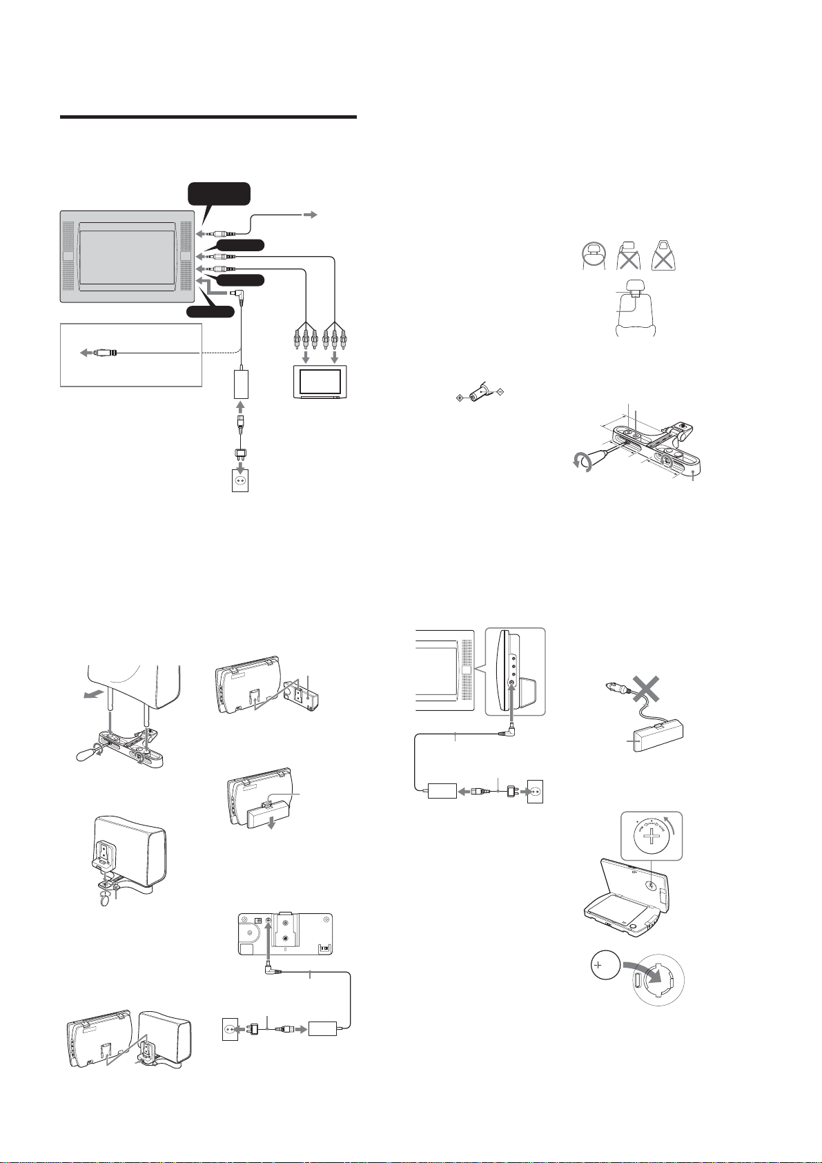
AEP, UK, Russian, E (NTSC) models
Connection
This player is supplied in two kinds of connection method. When using at home, connect it to the
AC outlet. When using in a car, connect the player using the supplied cigar lighter adapter.
When using the AC power supply
HEADPHONES/
To the cigar
lighter socket
Cigar lighter adapter
(supplied)
When using the
player in the car
OPTICAL OUT
A/V OUTPUT
A/V INPUT
DC IN 12V
OUTPUT
Optical cable
(not supplied)
Audio/video cable
(not supplied)
*
AC power
adaptor
(supplied)
To audio/
video input
connectors
AC power cord*
(supplied)
To a wall outlet
To a digital
amplifier,
etc.
TV, etc.
On A/V OUTPUT connectors
You can connect a TV to the A/V OUTPUT
connectors to output the contents being played
back on the player. Connect the yellow plugs
of the audio/video cable to the video
connectors on both the TV and the player, and
connect the white plugs to the white (left
audio) connectors and the red plugs to the red
(right audio) connectors respectively.
On A/V INPUT connectors
You can connect a VTR, etc. to the A/V INPUT
connectors to input the contents being played
back on the device. You can connect the device
in the same way as described on “On A/V
OUTPUT connectors” above.
On HEADPHONES jack
You can connect a set of headphones to the
HEADPHONES jack.
Notes
•When connecting another device to the player,
be sure to connect the player to the power
source after all other connections are completed.
• If an obstacle such as cigar ash is caught inside
the cigar lighter socket, the contact between the
power cord plug and the socket becomes
incomplete and the plug may get extremely hot
during use. To avoid this, check the socket and
clean it if necessary before connecting the power
cord.
*
Polarity of the plug
Attaching the headrest installation
kit to the seat
The player can be installed behind the headrest
by using the supplied headrest installation kit.
Seat types on which you can mount
the installation kit
•A seat with 2 headrest rods of diameter 10
mm to 15 mm.
•A seat with rods spaced between 42 mm and
192 mm.
Note
Depending on the seat type, it may not be possible
to mount this unit.
Ø10 mm~15 mm
42 mm~192 mm
Before attaching, adjust the rod spacing A and
depth positioning B depending on your
headrest.
Note that the depth positioning B should be
adjusted as closely as possible to the headrest
in order to prevent the monitor from vibrating.
15 mm
12 mm
B
A
A
Installation kit
* There are two types of AC power cords supplied. Use the appropriate one that fits the outlet in
your region.
1 Remove the headrest and attach the
installation kit to the rods.
You can adjust the lateral position of the
monitor by sliding the installation kit from
side to side before tightening the screw.
Front
Installation kit
2 Attach the installation cradle to the
installation kit and tighten the screw on
the bottom using things like a coin.
Installation
cradle
Installation kit
C
Adjust the angle of your monitor with the
knob C.
Note
The backside of the installation cradle should be
pressed against the headrest for the stable
installation.
Removing the player from the
installation cradle
Remove the player while pressing the button
on the installation cradle.
Push to release
Using the rechargeable battery
pack
Attach the rechargeable battery pack as
illustrated below.
Slide up the rechargeable battery pack until
you hear the click sound.
Removing the rechargeable battery
pack from the player
Push the release button on the rechargeable
battery pack and slide it off.
Charging the rechargeable battery
pack
Charge the rechargeable battery pack using AC
power adaptor and AC power cord. You can
charge the rechargeable battery pack while it is
attached to the unit.
To a wall
outlet
Rechargeable battery
pack MV-100BAT
(not supplied)
Push to release
AC power adaptor
(supplied)
AC power cord (supplied)
When attached to the main unit
AC power adaptor
(supplied)
AC power cord (supplied)
When to charge the rechargeable
battery
• Charge the rechargeable battery when
“LOW BATTERY” appears in the display.
• It usually takes about 6 hours* to complete
charging the battery. The lamp of the
rechargeable battery indicates the charging
conditions.
While charging: Lights in orange
Charging completed: Lights in green
Charging error: Flashes in green
*The charging time may vary depending on the
surrounding temperature.
Battery duration
Approximately 150 minutes** (fully charged)
** When used at room temperature.
When the monitor settings (S-MENU) are set to
default.
CAUTION
•Remove the rechargeable battery from the
main unit if you do not intend to use the
player for an extended period of time.
•Charge the rechargeable battery before use if
it has not been used for an extended period of
time.
•Once charging is completed, remove the AC
power adapter from the rechargeable battery.
Do not recharge the fully charged battery.
(Once charging is completed, it will take
about 60 minutes for the lamp of the battery
to light in green again.)
To a wall
outlet
•Do not charge the rechargeable battery using
the supplied cigar lighter socket. To charge
the rechargeable battery in a car, use the
connection box and battery rechargeable
cable supplied with optional Car Installation
Kit MV-100CAR.
Cigar lighter
adaptor
Rechargeable
battery
Inserting the back-up battery
Insert CR2032 battery into the battery
compartment of the player. This battery save
the memory data (clock setting and calendar
setting).
x
+ side facing up
8
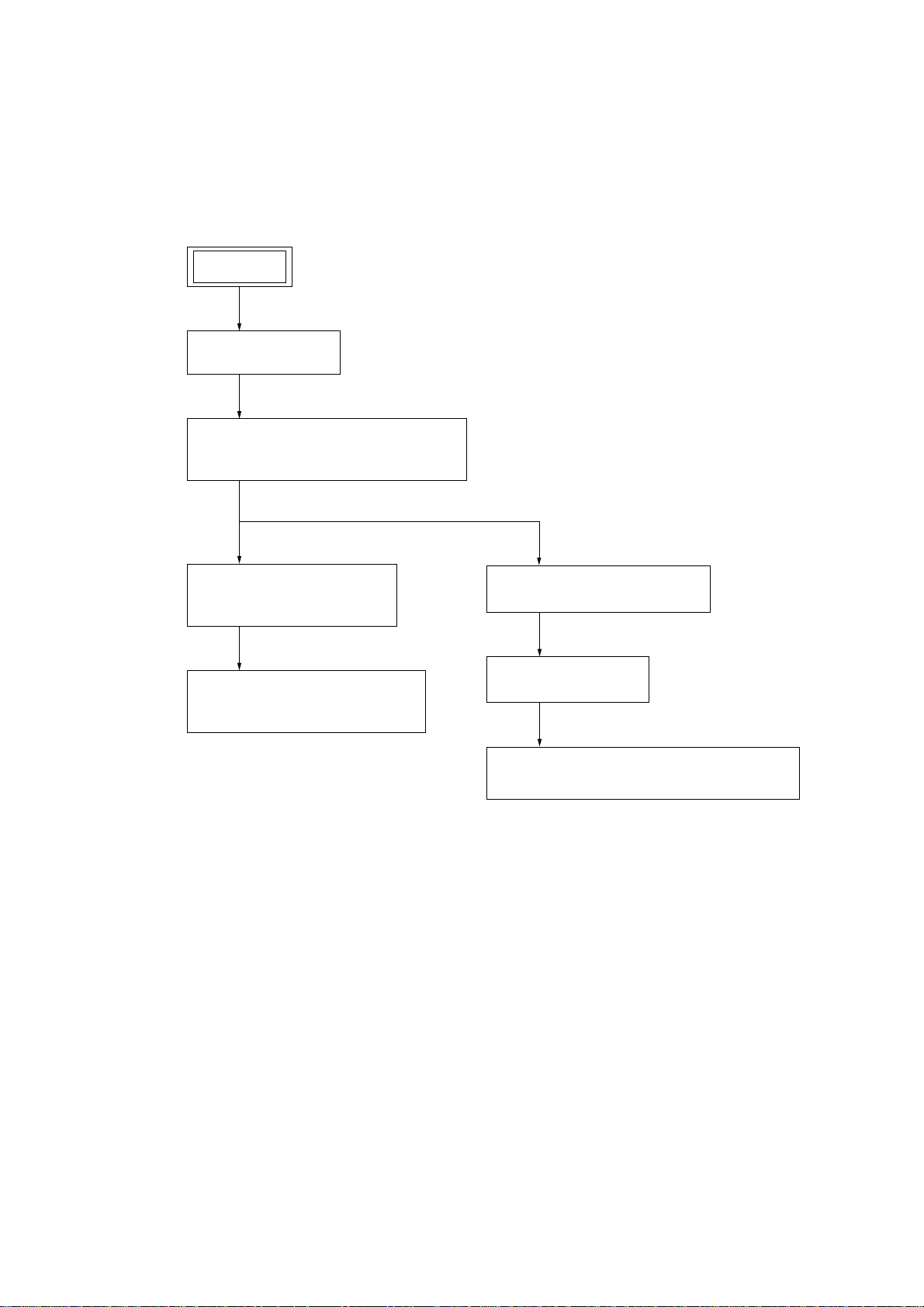
• This set can be disassembled in the order shown below.
3-1. DISASSEMBLY FLOW
SET
3-2. COVER (HINGE)
(Page 10)
3-3. FRONT/REAR CASE (MAIN) SECTION,
MONITOR SECTION
(Page 10)
MV-700HR
SECTION 3
DISASSEMBLY
3-4. OPTICAL PICK-UP BLOCK
(SDR-085T)
(Page 11)
3-5. MEMORY STICK CONNECTOR,
MAIN BOARD
(Page 11)
3-6. REAR CASE (LCD) SECTION
(Page 12)
3-7. MONITOR BOARD
(Page 12)
3-8. LIQUID CRYSTAL DISPLAY PANEL (LCD900)
(Page 13)
9
MV-700HR
)
)
Note: Follow the disassembly procedure in the numerical order given.
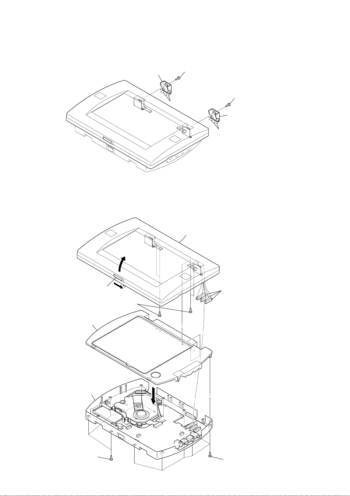
3-2. COVER (HINGE)
3
cover (hinge)
2
two claws
1
screw
(B 2 × 3)
2
two claws
1
screw
(B 2 × 3)
3
cover (hinge
3-3. FRONT/REAR CASE (MAIN) SECTION, MONITOR SECTION
7
monitor section
4
Open the monitor section.
5
four screws
(B 2
×
5)
6
front case (main) section
3
three connectors
(CN1005, CN1006, CN1007
10
4
rear case (main) section
1
five screws
(B P-TITE M2)
2
1
six screws
(B P-TITE M2)
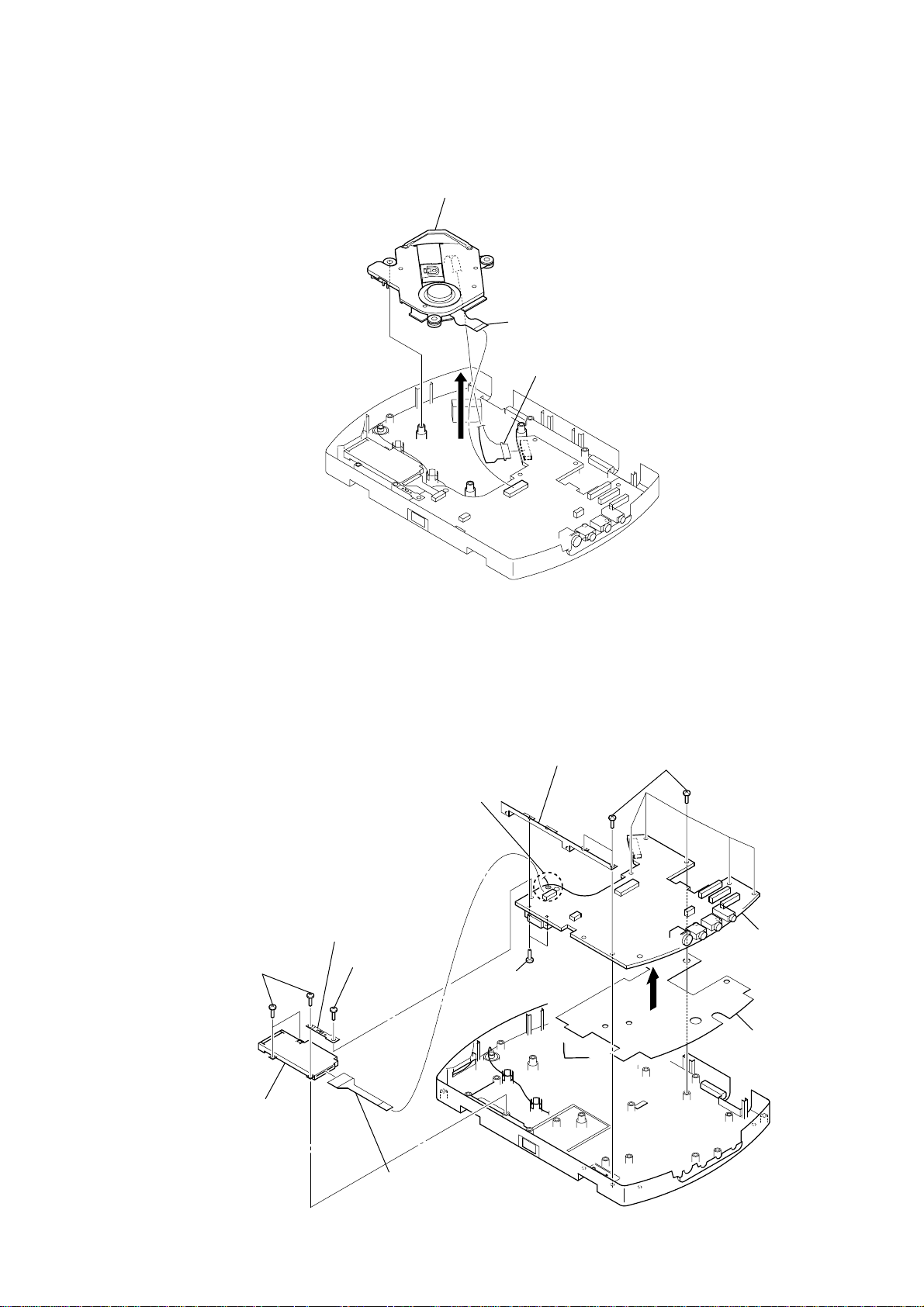
3-4. OPTICAL PICK-UP BLOCK (SDR-085T)
d
4
optical pick-up block (SDR-085T)
1
FFC 13P
(CN104)
3
OP flexible board
(CN103)
2
MV-700HR
3-5. MEMORY STICK CONNECTOR, MAIN BOARD
6
Remove the solder of
antenna lead wire.
3
bracket (MS)
2
three screws
(B 1.7
×
6)
5
memory stick connector
1
screw
(BTP 2
×
6)
q;
bracket (detach)
9
two screws
(M 1.6
7
seven screws
(BTP 2
×
6)
qa
MAIN boar
×
8)
8
qs
sheet (main)
4
flexible (MS) board
(CN105, memory stick connector)
11
MV-700HR
)
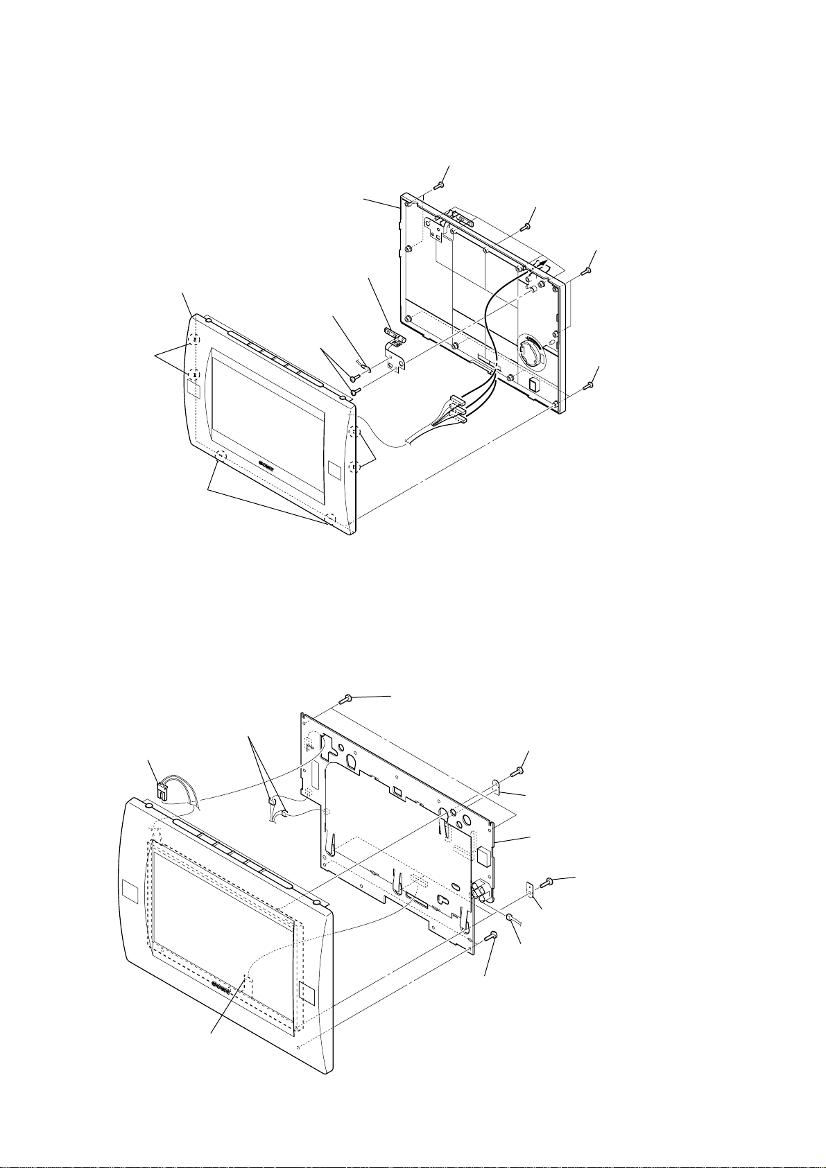
3-6. REAR CASE (LCD) SECTION
6
rear case (LCD) section
7
front case (LCD) section
3
2
two claws
5
hinge (R) assy
4
terminal
two screws
(B 2
×
5)
1
two screws
(B P-TITE M2)
1
five screws
(B P-TITE M2)
1
two screws
(B P-TITE M2)
1
four screws
(B P-TITE M2)
2
two claws
3-7. MONITOR BOARD
2
2
connector
(CN908)
two connectors
(CN904, CN912)
2
two claws
3
two screws
(BTP 2 × 6)
4
screw
(BTP 2 × 6)
5
retainer (LCD)
6
MONITOR board
12
1
LCD flexible board
(CN907)
3
two screws
(BTP 2 × 6)
5
three retainers (LCD
2
connector
(CN913)
4
three screws
(BTP 2 × 6)
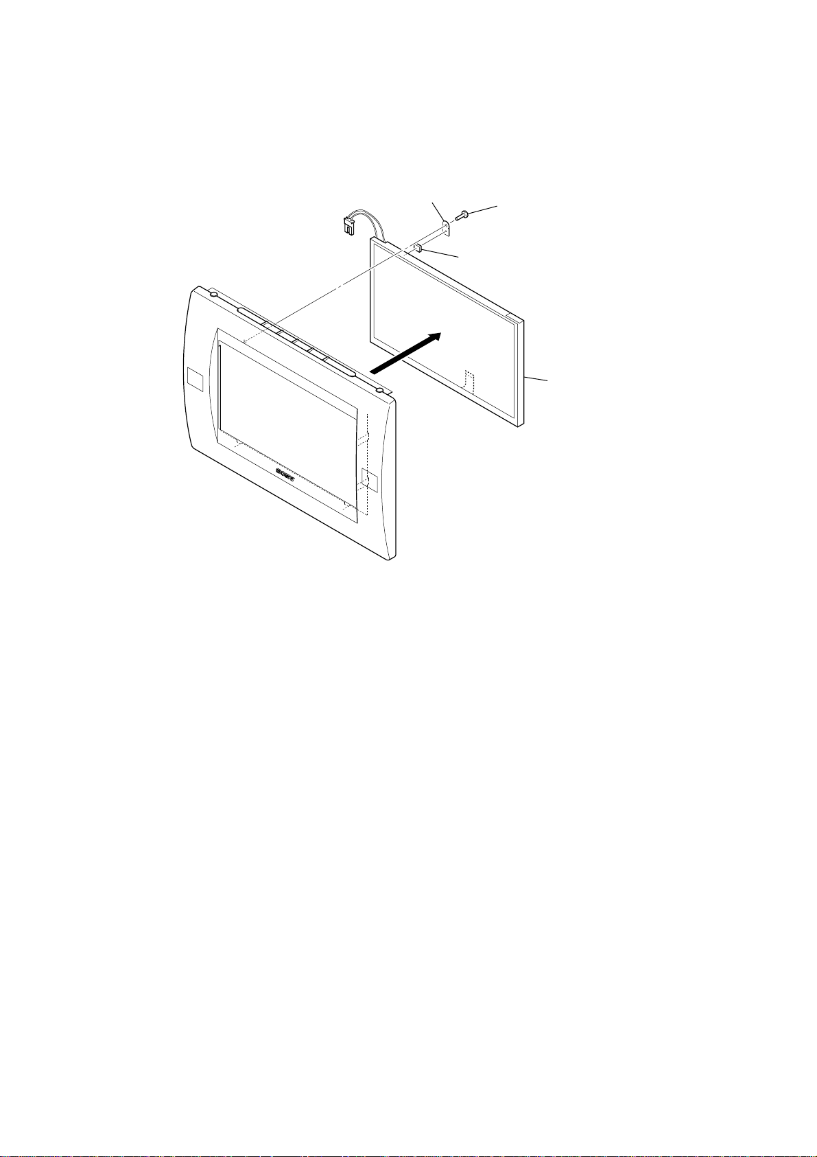
3-8. LIQUID CRYSTAL DISPLAY PANEL (LCD900)
l
2
retainer (LCD)
1
3
cushion (LCD)
screw
(BTP 2
×
6)
4
liquid crystal display pane
(LCD900)
MV-700HR
13
MV-700HR
SECTION 4
TEST MODE
Note: This set is able to setting the adjustment data, reset to factory default
and initialize the EEPROM (IC403 on the MONITOR board) in the
test mode.
ENTER THE TEST MODE
Procedure:
1. Press the [POWER] button to turn the power on.
2. While pressing the [S-MENU] and
[RESET] button.
3. The set is enter the test mode and display as bellow figure.
Display
MV-700HR TEST MODE MENU
1. NTSC/PAL SELECT
2. FOR FACTORY
3. LCD SETTING
4. HEAT PROTECTION
5. LOAD DEFAULT
6. SOFT RESET(EXIT)
Ver X.XXX
Note: If initial data is not written to the EEPROM (IC403 on the MONITOR
board) or data is clobbered, the set is not able to display normally
screen.
u buttons, press the
BATCH WRITING OF THE INITIAL DATA TO
EEPROM
In the test mode, by pressing the [VOL ---] button on the remote
commander at two seconds, batch writing is possible of the initial
data to EEPOM (IC403 on the MONITOR board).
3. LCD SETTING
This mode is not used in servicing.
4. HEAT PROTECTION
This mode is not used in servicing.
5. LOAD DEFAULT
This mode is not used in servicing.
6. SOFT RESET (EXIT)
Releasing the test mode.
OPERATION OF THE TEST MODE
All operations are performed using the bellow buttons.
Button Function
S-MENU Select the item
SOURCE Enter
VOLUME + Up the data value
VOLUME − Down the data value
RELEASING THE TEST MODE
In the test mode menu screen, press the [S-MENU] button to select
“6. SOFT RESET (EXIT)”, and press the [SOURCE] button to
release the test mode.
OPERATING THE EACH ITEM
1. NTSC/PAL SELECT
In this mode, switch the signal format system to NTSC or P AL.
2. FOR FACTORY
In this mode, change the data of adjustment data.
Enter this mode, it displays each adjustment item as follow.
1) Com Gain
2) Y Gain
3) Black Limit
4) White Limit
5) R-Sub BRT
6) B-Sub BRT
7) R-Sub CONT
8) B-Sub CONT
9) Gamma 1
10) Gamma 2
11) VCO Free Run
12) PLL/V Pos
13) H Pos
14
r
r
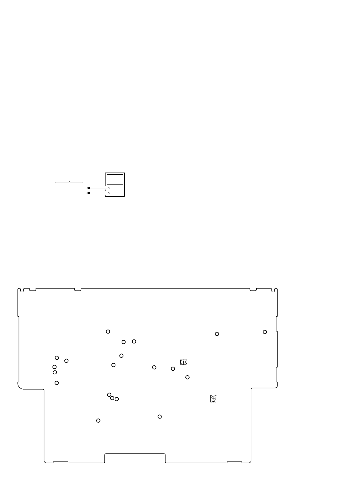
SECTION 5
TP1924
TP1938 (GND)
TP1955
– MAIN BOARD (Component Side) –
ELECTRICAL ADJUSTMENTS
MAIN SECTION
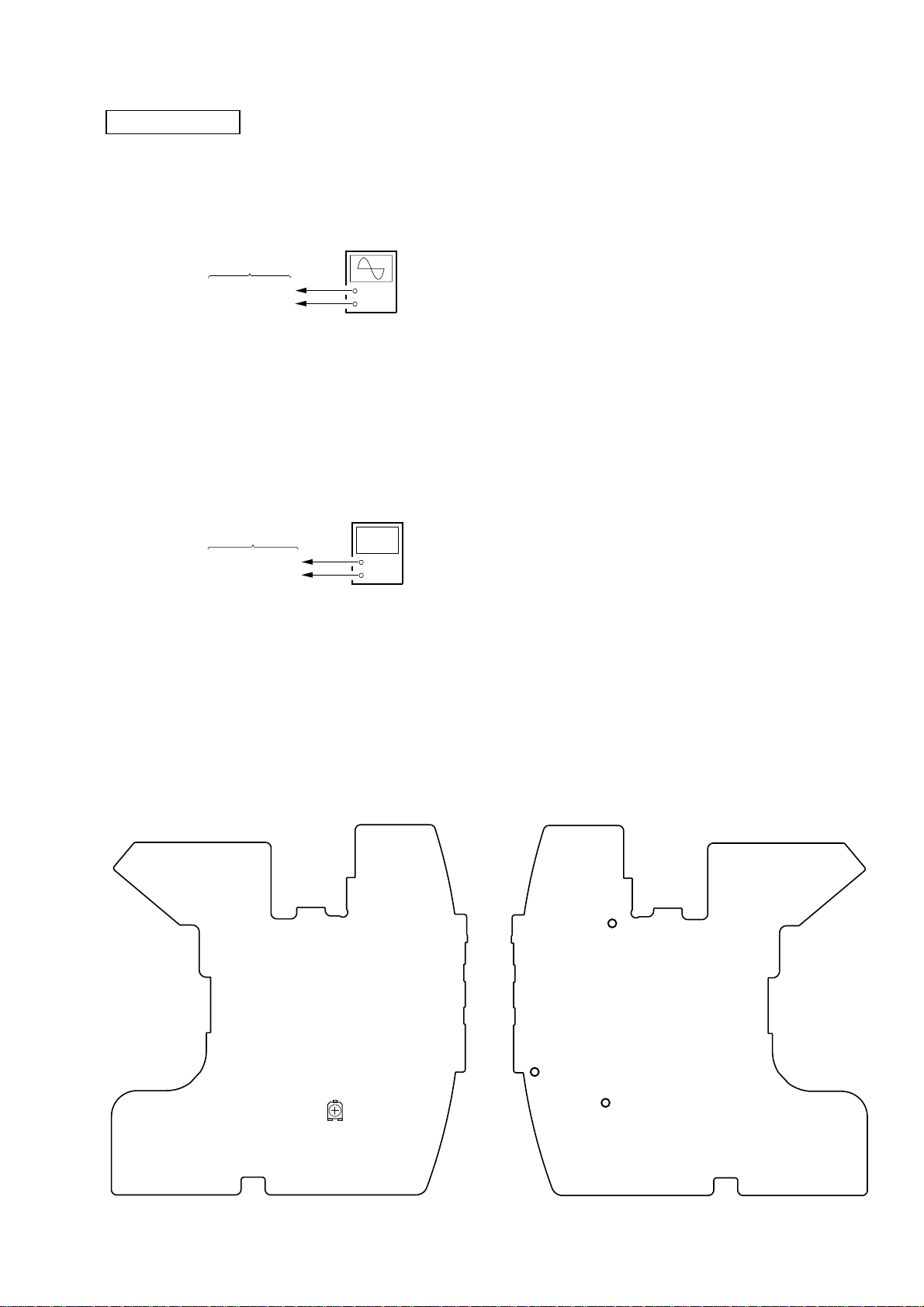
1. DC/DC CONVERTER ADJUSTMENT
1-1. Frequency Adjustment
Setting:
oscilloscope
or
frequency counte
MAIN board
TP1955
TP1938 (GND)
Procedure:
1. Connect an oscilloscope or frequency counter to the TP1955
and TP1938 (GND) on the MAIN board.
2. Press the [POWER] button to turn the power on.
3. Adjust the RV1001 on the MAIN board so that the value of
oscilloscope or frequency counter becomes 243.5 kHz ±0.5
kHz.
1-2. Other Voltages Check
Setting:
MAIN board
TP1924/TP1955
TP1938 (GND)
+
–
digital voltmete
+
–
MV-700HR
Procedure:
– VCC1 Voltage Check –
1. Connect a digital voltmeter to the TP1924 and TP1938 (GND)
on the MAIN board.
2. Press the [POWER] button to turn the power on.
3. Check that the value of digital voltmeter is 6.05 V ±0.2 V .
– VCC2 Voltage Check –
4. Connect the digital voltmeter to the TP1955 and TP1938
(GND) on the MAIN board.
5. Check that the value of digital voltmeter is 5.2 V ±0.2 V .
Adjustment Location:
– MAIN BOARD (Component Side) –
RV1001
15
MV-700HR
r
r
e
V
V
r
r
r
r
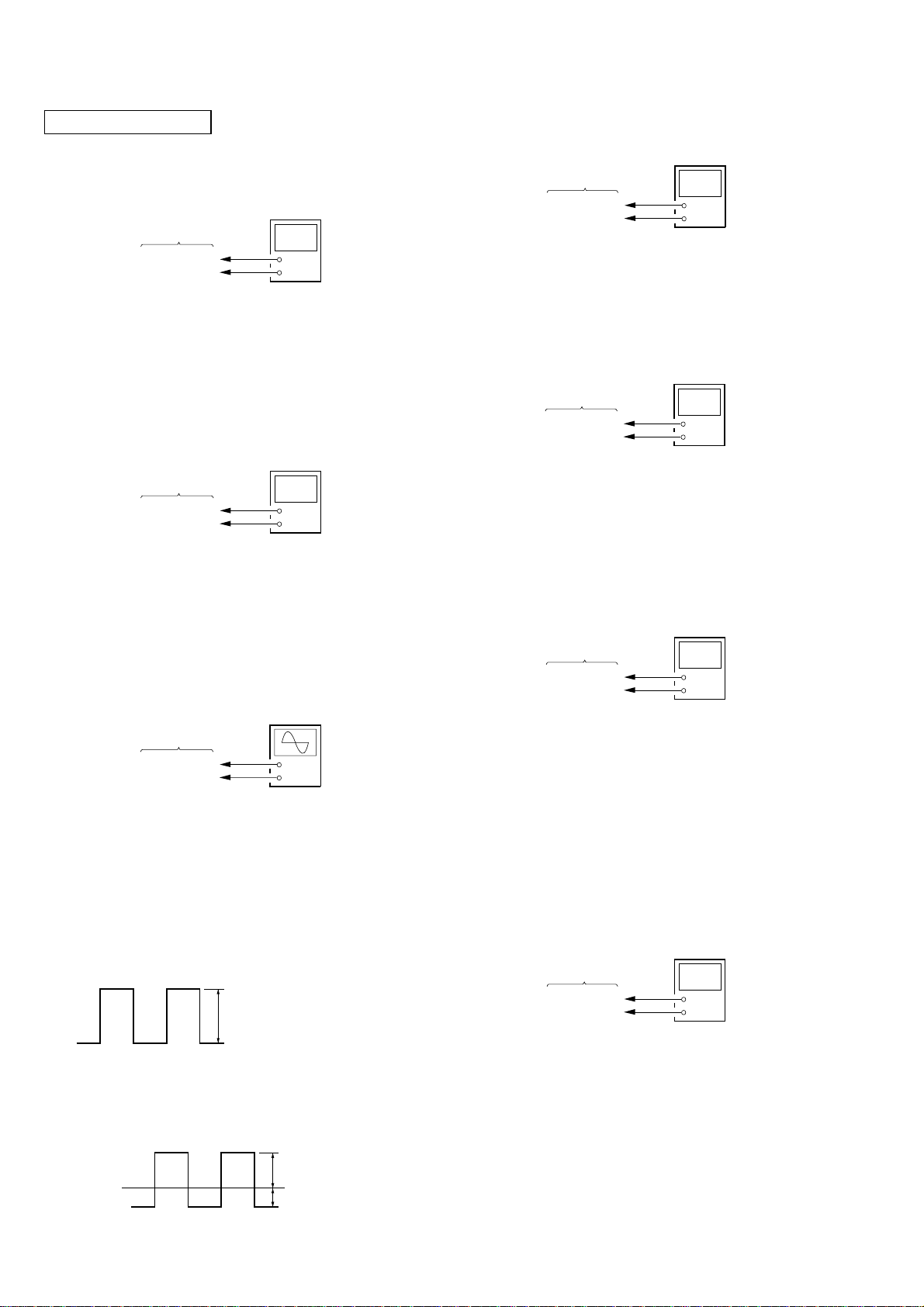
MONITOR SECTION
1. PLL ADJUSTMENT
1-1. PLL Voltage Adjustment
Setting:
digital voltmete
MONITOR board
TP802
TP929 (GND)
+
–
Procedure:
1. Connect a digital voltmeter to the TP802 and TP929 (GND)
on the MONITOR board.
2. Press the [POWER] button to turn the power on.
3. Adjust the RV801 on the MONITOR board so that the value
of digital voltmeter becomes 2.2 V ±0.15 V .
1-2. PLL Frequency Check
Setting:
frequency counte
MONITOR board
TP801
TP929 (GND)
+
–
Procedure:
1. Connect a frequency counter to the TP801 and TP929 (GND)
on the MONITOR board.
2. Press the [POWER] button to turn the power on.
3. Check that the value of frequency counter is 28.699 MHz ±1
kHz.
2. V-COM ADJUSTMENT
Setting:
oscilloscop
MONITOR board
TP917
TP929 (GND)
Procedure:
– Voltage Set-up Adjustment –
1. Connect an oscilloscope to the TP917 and TP929 (GND) on
the MONITOR board.
2. Press the [POWER] button to turn the power on.
3. Enter the test mode, and enter the “2. FOR FA CTOR Y” mode.
(refer to “SECTION 4. TEST MODE”)
4. Press the [S-MENU] button to display “Com Gain”.
5. Adjust by pressing the [VOLUME +]/[VOLUME --] buttons so
that the voltage of oscilloscope becomes 7.3 Vp-p ±0.1 V .
7.3 Vp-p ± 0.1
+
–
3. INVERTER FREQUENCY CHECK
Setting:
frequency counte
MONITOR board
TP434
TP388 (GND)
+
–
Procedure:
1. Connect a frequency counter to the TP434 and TP388 (GND)
on the MONITOR board.
2. Check that the value of frequency counter is 51 kHz ±2.5 kHz.
4. OSD DOT CLOCK CHECK
Setting:
frequency counte
MONITOR board
TP751
TP753 (GND)
+
–
Procedure:
1. Connect a frequency counter (high impedance) to the TP751
and TP753 (GND) on the MONITOR board.
2. Press the [POWER] button to turn the power on.
3. Check that the value of frequency counter is 6.5 MHz ±0.2
MHz.
5. NTSC SUB CARRIER CHECK
Setting:
frequency counte
MONITOR board
TP701
TP703 (GND)
+
–
Procedure:
1. Connect a frequency counter to the TP701 and TP703 (GND)
on the MONITOR board.
2. Press the [POWER] button to turn the power on.
3. In the normal mode, press the [SOURCE] button to select the
“VIDEO” mode.
4. Input NTSC video signal to the A/V INPUT jack (J1004 on
the MAIN board).
5. Check that the value of frequency counter is 3.579545 MHz
±100 Hz.
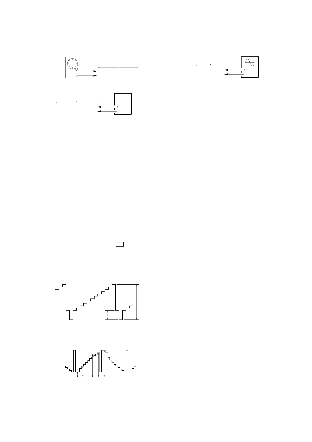
6. PAL SUB CARRIER CHECK
Setting:
frequency counte
MONITOR board
TP701
TP703 (GND)
+
–
6. Press the [SOURCE] button and write the data to EEPROM
(IC403 on the MONITOR board).
– Waveform Position Set-up Adjustment –
7. Adjust the RV851 on the MONITOR board so that A value
of waveform becomes –3.0 V ±0.1 V .
4.3 V ± 0.1 V
16
0 V
A
: – 3.0 V ± 0.1
Procedure:
1. Connect a frequency counter to the TP701 and TP703 (GND)
on the MONITOR board.
2. Press the [POWER] button to turn the power on.
3. In the normal mode, press the [SOURCE] button to select the
“VIDEO” mode.
4. Input P AL video signal to the A/V INPUT jack (J1004 on the
MAIN board).
5. Check that the value of frequency counter is 4.433619 MHz
±100 Hz.
MV-700HR
e
7. IR TRANSMITTER CHECK
Setting:
AF oscillator
MONITOR board
TP501 (L), TP502 (R)
TP505 (GND)
400 Hz, –20 dB
frequency counter
MONITOR board
TP503 (L), TP504 (R)
TP505 (GND)
+
–
Procedure:
1. Connect an AF oscillator to the TP501 (L) and TP505 (GND),
and input the audio signal (400 Hz, –20 dB).
2. Connect a frequency counter to the TP503 (L) and TP505
(GND) on the MONITOR board.
3. Press the [POWER] button to turn the power on.
4. Press the [S-MENU] button nine times to display “IR
HEADPHONE”, and press the [VOLUME +] button to select
“ON”.
5. Check that the value of frequency counter is 2.3 MHz ±45
kHz.
6. In the same manner, check that the frequency of R-CH is 2.8
MHz ±45 kHz.
8. VIDEO ADJUSTMENT
Note: Perform the following adjustment items in test mode.
1 Contrast Level of Luminance Signal
Setting:
oscilloscop
MONITOR board
TP907
TP929 (GND)
+
–
Procedure:
1. Connect an oscilloscope to the TP907 and TP929 (GND) on
the MONITOR board.
2. Press the [SOURCE] button to display “Y Gain”.
3. Adjust by pressing the [VOLUME +]/[VOLUME --] buttons so
that the D value of waveform (fig. 8-2) becomes 3.8 V ±0.1
V.
2 Black Limiter Level
Procedure:
1. In the “1 Contrast Level of Luminance Signal” status, press
the [SOURCE] button to display “Black Limit”.
2. Adjust by pressing the [VOLUME +]/[VOLUME --] buttons so
that the A value of waveform (f ig. 8-2) becomes 1.05 V ±0.15
V.
3 White Limiter Level
Procedure:
1. In the “2 Black Limiter Level” status, press the [SOURCE]
button to display “White Limit”.
2. Adjust by pressing the [VOLUME +]/[VOLUME --] buttons so
that the E value of waveform (f ig. 8-2) becomes 3.95 V ±0.15
V.
Common Setting:
1. Press the [POWER] button to turn the power on.
2. Set the signal format system to NTSC. (refer to “SECTION 4.
TEST MODE”)
3. While pressing the [S-MENU] and u buttons, press the
[RESET] button to enter the test mode, and enter the “2. FOR
FACTORY” mode. (refer to “SECTION 4. TEST MODE”)
4. Input 10 steps signal (NTSC, without burst) to the A/V INPUT
jack (J1004 on the MAIN board) from pattern generator.
Waveform of input signal
1 Vp-p
0.286 V
fig. 8-1
Waveform of output signal
(TP906, TP907, TP908)
4 R-sub Bright
Procedure:
1. In the “3 White Limiter Level” status, connect the
oscilloscope to the TP906 and TP929 (GND) on the
MONITOR board.
2. Press the [SOURCE] button to display “R-Sub BRT”.
3. Adjust by pressing the [VOLUME +]/[VOLUME --] buttons so
that the A value of waveform (f ig. 8-2) becomes 1.05 V ±0.15
V.
5 B-sub Bright
Procedure:
1. In the “4 R-sub Bright” status, connect the oscilloscope to
the TP908 and TP929 (GND) on the MONITOR board.
2. Press the [SOURCE] button to display “B-Sub BRT”.
3. Adjust by pressing the [VOLUME +]/[VOLUME --] buttons so
that the A value of wav eform (fig. 8-2) becomes 1.0 V
–+00..21 V
6 R-ch Sub Contrast
Procedure:
1. In the “5 B-sub Bright” status, connect the oscilloscope to
the TP906 and TP929 (GND) on the MONITOR board.
2. Press the [SOURCE] button to display “R-Sub CONT”.
3. Adjust by pressing the [VOLUME +]/[VOLUME --] buttons so
that the D value of waveform (fig. 8-2) becomes 3.8 V ±0.1
V.
.
V
0 V
AB C DE
fig. 8-2
7 B-ch Sub Contrast
Procedure:
1. In the “6 R-ch Sub Contrast” status, connect the oscilloscope
to the TP908 and TP929 (GND) on the MONITOR board.
2. Press the [SOURCE] button to display “B-Sub CONT”.
3. Adjust by pressing the [VOLUME +]/[VOLUME --] buttons so
that the D value of waveform (fig. 8-2) becomes 3.8 V ±0.1
V.
17
MV-700HR
r
8 Gamma 1
Procedure:
1. In the “7 B-ch Sub Contrast” status, connect the oscilloscope
to the TP907 and TP929 (GND) on the MONITOR board.
2. Press the [SOURCE] button to display “Gamma 1”.
3. Adjust by pressing the [VOLUME +]/[VOLUME --] buttons so
that the B value of wa veform (f ig. 8-2) becomes 2.1 V ±0.15
V.
9 Gamma 2
Procedure:
1. In the “8 Gamma 1” status, press the [SOURCE] button to
display “Gamma 2”.
2. Adjust by pressing the [VOLUME +]/[VOLUME --] buttons so
that the C value of wa veform (f ig. 8-2) becomes 3.6 V ±0.15
V.
q; VCO Free Run
Setting:
frequency counte
MONITOR board
TP711
TP716 (GND)
+
–
Procedure:
1. In the “9 Gamma 2” status, connect a frequency counter to
the TP711 and TP716 (GND) on the MONITOR board.
2. Press the [SOURCE] button to display “VCO Free Run”.
3. Adjust by pressing the [VOLUME +]/[VOLUME --] buttons so
that the value of frequency counter becomes 15.734 kHz ±50
Hz.
4. Confirm that the displayed screen is normally display.
qa Vertical Position
Procedure:
1. In the “q; VCO Free Run” status, input the monoscope signal
to the A/V INPUT jack (J1004 on the MAIN board).
2. Press the [SOURCE] button to display “PLL/V Pos”.
3. Adjust by pressing the [VOLUME +]/[VOLUME --] buttons so
that the vertical position of screen on the monitor becomes
the most suitable.
qs Horizontal Position
Procedure:
1. In the “qa Vertical Position” status, press the [SOURCE] button
to display “H Pos”.
2. Adjust by pressing the [VOLUME +]/[VOLUME --] buttons so
that the horizontal position of screen on the monitor becomes
the most suitable.
3. Press the [S-MENU] button to select the “EXIT”, and press the
[SOURCE] button to return to the “TEST MODE MENU”
screen.
Adjustment Location:
– MONITOR BOARD (Component Side) –
TP751
TP753 (GND)
TP501 (L)
TP502
(R)
TP504 (R)
TP503 (L)
TP505 (GND)
TP929 (GND)
TP701
TP908
TP907
TP703 (GND)
TP716 (GND)
TP906
TP711
TP917
TP801
RV801
TP802
TP388 (GND)
RV851
TP434
18
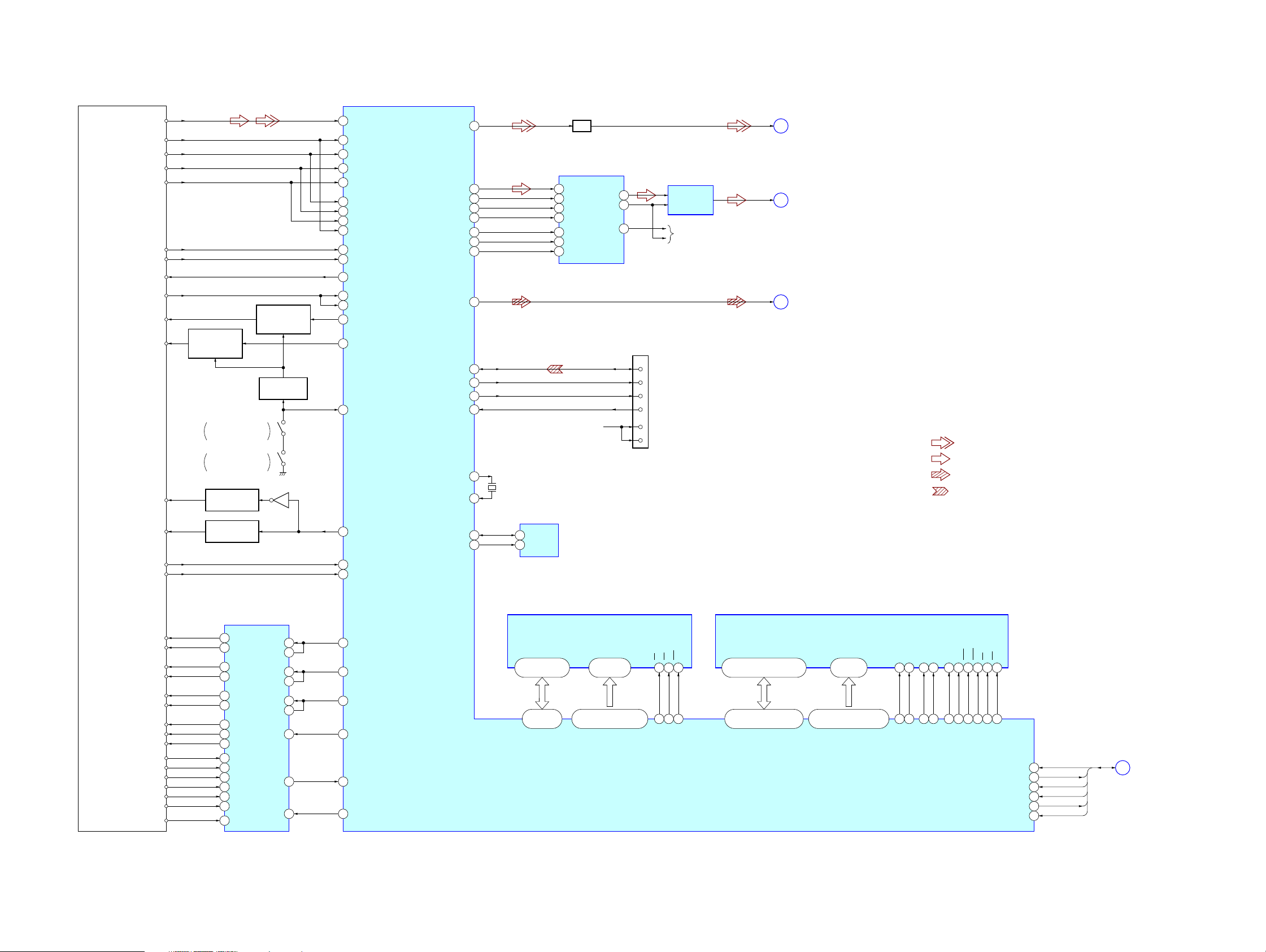
6-1. BLOCK DIAGRAM – DVD Section –
MV-700HR
SECTION 6
DIAGRAMS
VREF (2.2V)
DVD LD+
OPTICAL PICK-UP
BLOCK
IMON
CD LD+
DVD VR
DVD VR
RF
TD
TA
TB
TC
T1
T2
AUTOMATIC
POWER CONTROL
S101
S102
(FOR DVD) Q335
LD ON SWITCH
Q336
Q331
AUTOMATIC
POWER CONTROL
(FOR CD) Q337
DISC LID
OPEN/CLOSE DETECT
DISC LID
OPEN/CLOSE DETECT
DVD/CD SWITCH
(FOR DVD) Q333
DVD/CD SWITCH
(FOR CD) Q332
6
8
9
10
11
2
3
4
5
18
19
29
20
21
22
23
49
114
DVDRFIP
MA
MB
MC
MD
DVDA
DVDB
DVDC
DVDD
TNI
TPI
V20
MDI1
MDI2
LDO2
LDO1
TMS
DVD/CD
YUV3/CVBS
ASDATA0
ACLK
ABCK
ALRCK
SPDIF
MS_SDIO
MS_CLK
MS_BS
MS_INS
XTALO
XTALI
EEP_DA
EEP_CK
MD
MC
ML
198
217
215
214
213
101
99
104
225
176
174
177
89
LPF
D/A CONVERTER
DIN
2
SCKI
16
BCKIN
1
LRCK
3
MD
13
MC
14
ML
15
IC301
LOUT
VCOM
ROUT
4
8
2
6
3
9
MS_SDIO
MS_CLK
MS_BS
MS_INS
C33VDVD +3.3V
C33V
DIFFERENTIAL
AMP
IC302
R-CH
7
10
8
CN105
CVBS
DVD-L
SPDIF
A
B
H
(Page 21)
(Page 20)
(Page 20)
• R-ch is omitted due to same as L-ch.
• SIGNAL PATH
: DVD/CD PLAY (VIDEO)
: DVD/CD PLAY (ANALOG AUDIO OUT)
228
X101
27MHz
229
EEPROM
IC103
103
102
SDA
5
SCL
6
: DVD/CD PLAY (DIGITAL AUDIO OUT)
: MEMORY STICK (AUDIO/VIDEO)
FE1
FE2
FCS+
FCS–
TRK+
TRK–
SL+
SL–
HU+
HU–
HV+
HV–
HW+
HW–
SA
12
SB
13
FOCUS/TRACKING COIL DRIVE,
SPINDLE/SLED MOTOR DRIVE
IC351
FO2
24
RO2
23
RO3
19
FO3
20
FO1
26
RO1
25
U
V
W
H–
A1
37
A2
39
A3
40
H1H
28
H1L
29
H2H
30
H2L
31
H3H
32
H3L
33
VH
34
IN2
FB2
IN3
FB3
IN1
FB1
ECR
STBY
FOO
9
12
8
13
10
11
5
FG
3
18
42
TRO
41
FMO
38
DMO
37
FG
47
STBY
50
29, 31, 33, 35,
38, 40, 42, 44
81 – 84,
86 – 88, 91
FLASH ROM
IC104
DQ15/A-1, A0 – A19DQ0 – DQ7
45, 25 – 16,
9 – 1, 48
93, 78, 53 – 59, 75, 74,
72 – 67, 92, 60, 61, 76
IOA0 – IOA20AD0 – AD7
CE
OE
WE
26
28
11
77
79
66
XIOOE
XIOCS
XIOWR
RF AMP, SERVO DSP,
MPEG DECODER
IC101
2, 4, 5, 7, 8, 10, 11, 13, 42,
44, 45, 47, 48, 50, 51, 53
115, 117, 118, 120, 121,
123 – 126, 128 – 133, 135
158 – 160, 162, 164 – 166
SD-RAM
IC105
A0 – A11DQ0 – DQ15
22 – 26,
29 – 35
146, 147, 149 – 151,
RA0 – RA11RD0 – RD15
LDQM
A13
A12
CLK
20
21
38
143
145
156
BA0
BA1
RCLK
UDQM
CKE
37
157
CKE
15
113
39
137
DQM0
18
140
DQM1
RAS
17
139
XRAS
CAS
19
142
XCAS
CS
16
138
XRCS
WE
XRWE
XIFCS
XIFBUSY
XPRST
SCK
SO
178
SI
170
179
169
168
110
XSDO
XSIO
XSCK
XIFCS
XIFBUSY
RESET
C
(Page 20)
MV-700HR
1919
MV-700HR
Ver. 1.2
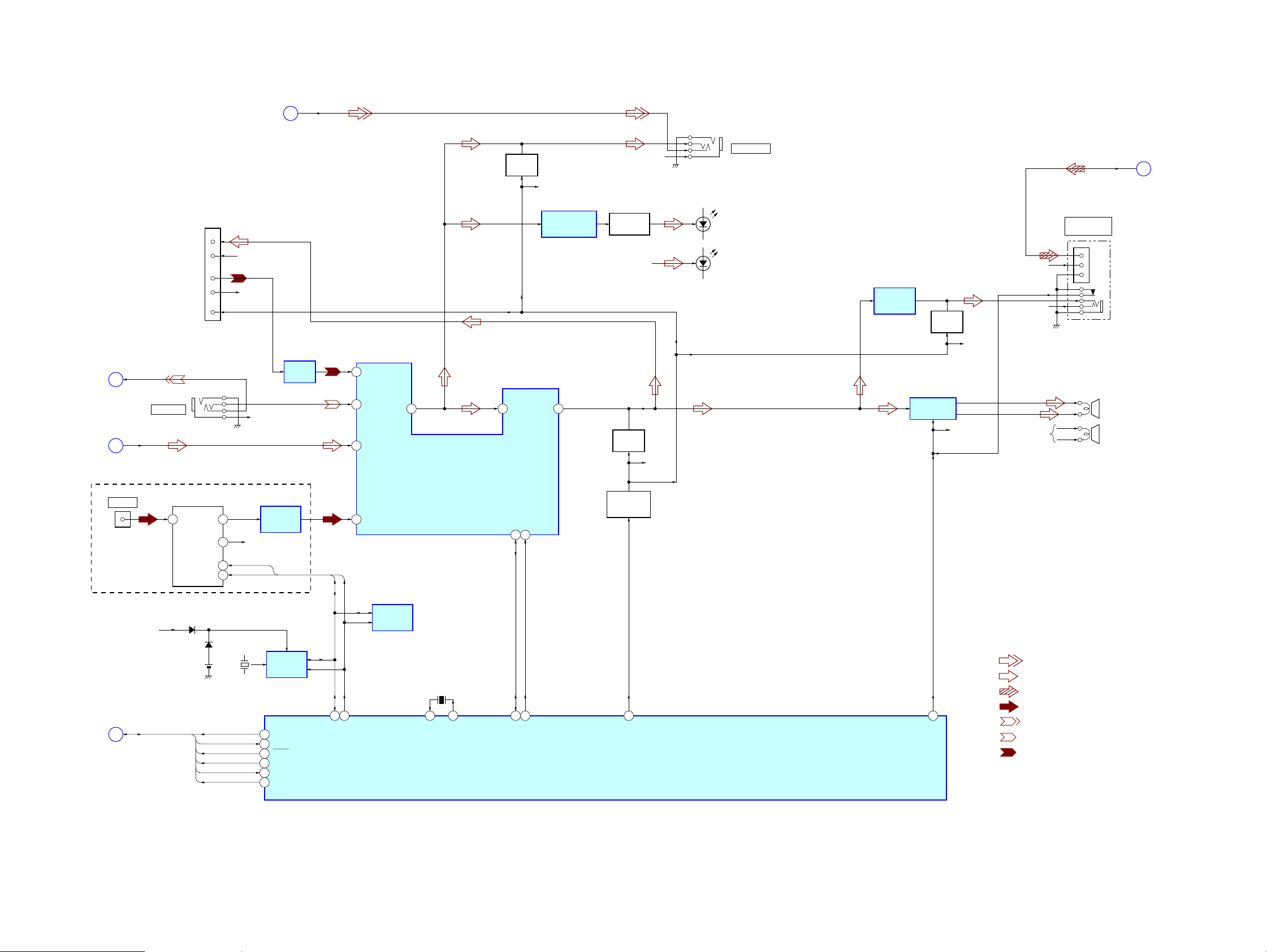
6-2. BLOCK DIAGRAM – AUDIO Section –
(Page 21)
(Page 19)
(US, CND, E (PAL), TW, KR, AUS, CH)
(Page 19)
D
B
TM1901
EXT ANT
C
AV IN VIDEO
DVD-L
B+ 4V
L-OUT
R-OUT
L IN
R IN
A MUTE
J1004
A/V INPUT
FM TUNER UNIT
IC1903
ANT
16
D804
D422, 426
BATT101
LITHIUM BATTERY
(CR2032)
CN1003 (1/3)
(CRADLE)
9
10
12
13
5
LCH
10
RCH
11
SDA
6
SCL
7
XSDO
XSIO
XSCK
XIFCS
XIFBUSY
RESET
(Page 21)
R-CH
R-CH
R-CH
X402
32.768kHz
R-CH
SDA
SCL
16
15
17
11
12
8
LOW-PASS
FILTER
IC1904
VCC
REAL TIME
CLOCK
IC419
SOO
SIO
SCKO
XIFCS
XIFBUSY
MTRST
AV OUT VIDEO
G
AMP
IC1352
13
SDA
14
*SDA
SCL
*SCL
10 IN1_L
12 IN2_L
6 DVD_L
TU_L
8
SELL
EEPROM
IC403
4
AUDIO INPUT SELECT,
ELECTRICAL VOLUME
X401
4.19MHz
41 40
X1
IC1401
X2
3
MUTING
Q1101
INL
18SI17
7
S-SDA
R-CH
OUT L
SCL
6
S-SCL
IR TRANSMITTER
MODULATOR
IC501
21
LED DRIVE
Q501
R-CH
MUTING
Q1103
MUTING
CONTROL
Q1551 – 1553
53
AMUTE
R-CH
R-CH
J1003
A/V OUTPUT
D501, 502
(IR TRANSMITTER)
(L-CH)
D503, 504
(IR TRANSMITTER)
(R-CH)
SYSTEM CONTROLLER
IC401 (1/3)
HEADPHONE
AMP
IC1301
MUTING
Q1104
SPEAKER AMP
IC1101
62
AMP-ON
R-CH
DVD +5V
R-CH
R-CH
R-CH
• Abbreviation
AUS: Australian model
CH : Chinese model
CND: Canadian model
KR : Korean model
TW : Taiwan model
• R-ch is omitted due to same as L-ch.
• SIGNAL PATH
: DVD/CD PLAY (VIDEO)
: DVD/CD PLAY (ANALOG AUDIO OUT)
: DVD/CD PLAY (DIGITAL AUDIO OUT)
: TUNER
: A/V INPUT (VIDEO)
: A/V INPUT (AUDIO)
: CRADLE INPUT (AUDIO)
J1001
HEADPHONES
/OPTICAL OUT
OUT
VCC
GND
SP1
(L-CH)
SP2
(R-CH)
SPDIF
H
(Page 19)
MV-700HR
2020
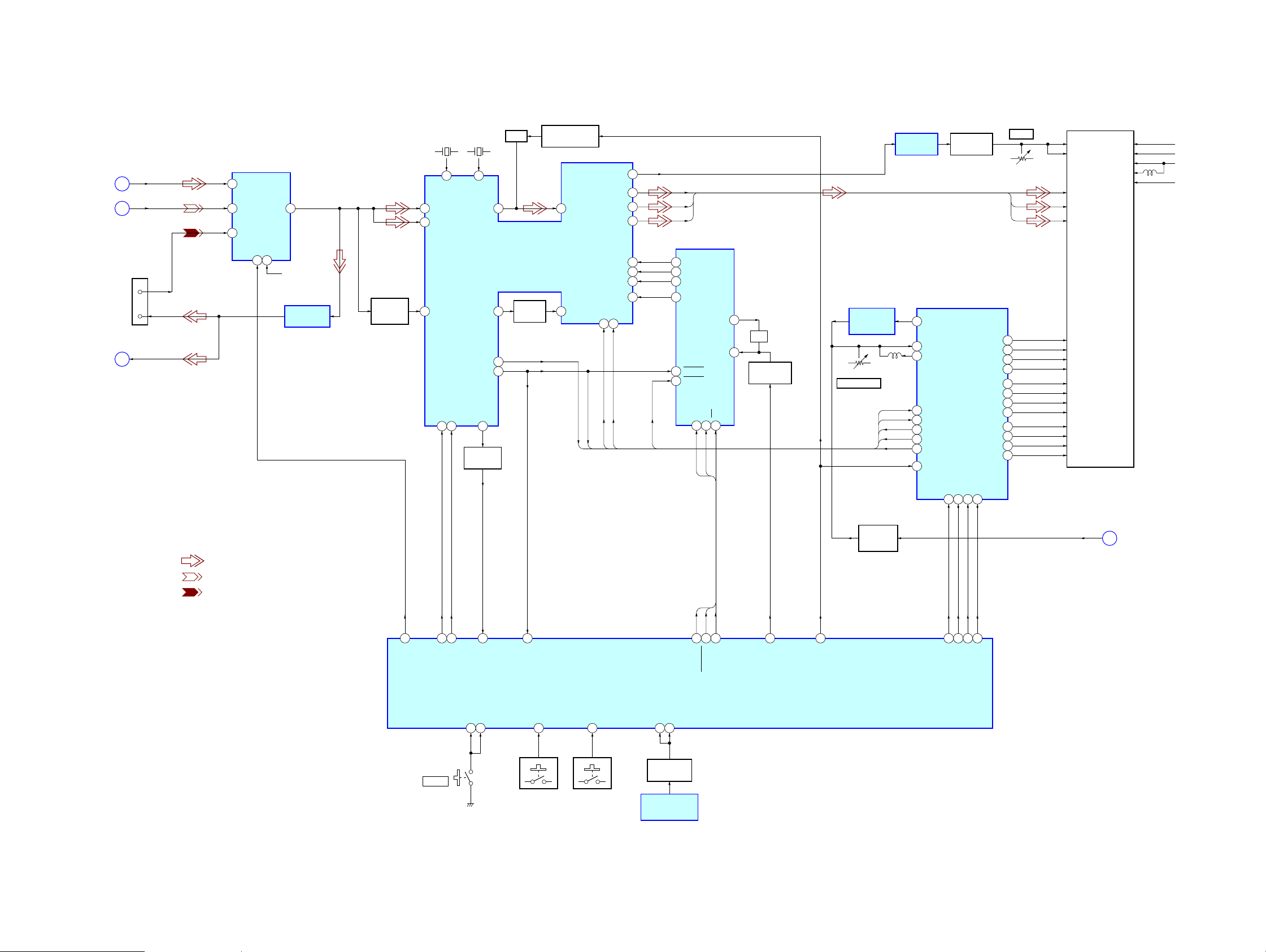
6-3. BLOCK DIAGRAM – VIDEO Section –
VIDEO INPUT
SELECT
IC1701
(Page 19)
(Page 20)
CVBS OUT
(Page 20)
CVBS IN
CVBS
A
AV IN VIDEO
D
CN1003 (2/3)
(CRADLE)
14
7
AV OUT
VIDEO
G
5 VIN3
1 VIN1
3 VIN2
7VO
SW2
SW1
4
2
CRADLE +9V
VIDEO BUFFER
IC1702
VIDEO
BUFFER
Q701, 702
X701
3.58MHz
63
VXO-NTSC
CTRAPOUT
YIN
52
CIN
57
CSYNCIN
46
CSYNCOUT
V-SDA48V-SCK47HSYNCLOCK
X702
4.43MHz
64
VXO-PAL
HDOUT
VDOUT
39
SYNC LOCK
Q705, 706
TRAP
53
RGB DECODER
34
32
31
IC701
BUFFER
Q707
PAL/NTSC SWITCH
Q703, 704
CTRAPIN
54
VDIN
35
HD
VD
VCOMOUT
R-OUT
G-OUT
B-OUT
R-IN2
G-IN2
B-IN2
BLAK36POL
18
BLAK
POL
MV-700HR
LIQUID CRYSTAL
RV851
STV1
V-COM
R
G
B
20
26STV2
23STH1
24STH2
29CPH1
27CPH2
25CPH3
16CPV
19OEV1
18OEV2
17OEV3
21OEH
V-COM AMP
IC851
28
HOUT
R
G
B
OSD DRIVER
16
VR
17 VG
18 VB
15 VBLK
19 VSYNC
20 HSYNC
IC751
OSC_OUT
DATA
1
3
DATA
CLK
SCLK2CS
CS
7
8OSC_IN
OSC
CLOCK SHIFT
Q751
PHASE
COMPARATOR
IC802
RV801
PLL VOLTAGE
HD
VD
BLAK
POL
HOUT
33
36 VCOI
37 VCOO
2 HSYNCIN
5 VDBIN
8 BLACK
14 POL
6 HOUT
46 NP
26
21
19
14
15
16
17
YS
LCD CONTROLLER
PD
V-COM BIAS
Q851 – 855
IC801
DISPLAY MODULE
LCD900 (1/2)
VCOM
VGON 17V
VDD 3.3V
VCOM
RED
GREEN
BLUE
STV1
STV2
STH1
STH2
CPH1
CPH2
CPH3
CPV
OEV1
OEV2
OEV3
OEH
VEE 5.0V
VSS –13V
VGON +17V
VDD +3.3V
VEE +5V
VB
VSS –13V
• SIGNAL PATH
: DVD PLAY (VIDEO)
: A/V INPUT (VIDEO)
: CRADLE INPUT (VIDEO)
LTBOX
QHSEL31JUST
CPHSEL
12
4
3
PLL ON
SWITCH
Q802, 803
CS
CLK
DATA
57
59
61
26
51
SW1
S412
POWER
52
V-SDA
V-SCK
KEY_PW
30
SYNC_DET
KEY_HALT
44
63
43
VD
KEY_IN
28
S401 – 404
KEY_DVD
27
S406 – 409
REM_HALT45REM_IN
47
SIRCS BUFFER
Q406
REMOTE CONTROL
RECEIVER
IC404
20
22
19
OSD_CS
OSD_CLK
OSD DATA
SYSTEM CONTROLLER
IC401 (2/3)
18
DOT SHIFT
23
N/P
58
SIDE2
SIDE1
ZOOM
JUST
RADIO-ON
E
(Page 22)
MV-700HR
2121
MV-700HR
Ver. 1.2
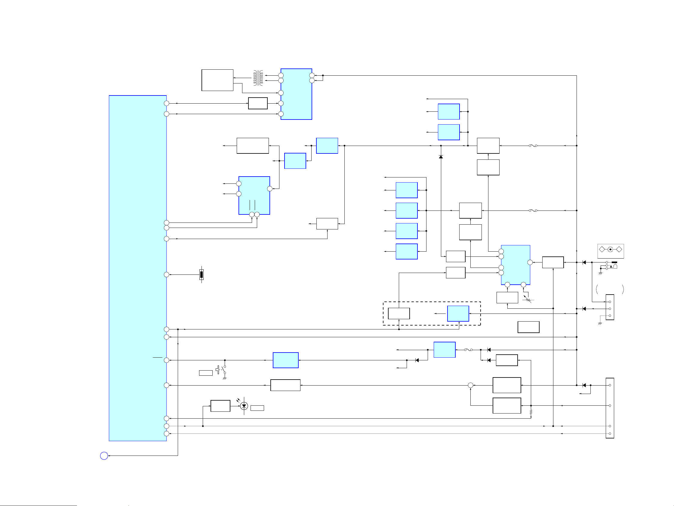
6-4. BLOCK DIAGRAM – POWER SUPPLY Section –
SYSTEM CONTROLLER
IC401 (3/3)
THRMAL
RADIO_ON
PW_DET
HOME CHECK
ACC CHECK
RESET
PW_IN
PW-ON
INVERTER
TRANSFORMER
T1033
LIQUID CRYSTAL
DISPLAY MODULE
LCD900 (2/2)
(BACK LIGHT UNIT)
DIMMER
Q601
56TFT-ON
+17V
VGON +17V
+7.5V
VSS –13V
4SHDN1
3SHDN2
50IR-ON
33
64
32
36
46
29
2
48
TH1001
S413
RESET
LED DRIVE
Q410
REGULATOR
D903, 904, 908, 909
VDD +3.3V
DC/DC CONVERTER
IC901
1 VOUT1
5D2
SHDN19SHDN2
8
D5
POWER
LCD BACK LIGHT
8 OUTL
13 OUTR
2
IL
1 ABRT60DIMMER
5EN
REGULATOR
3VIN
RESET SIGNAL
GENERATOR
IC402
BATTERY DETECT
Q1006
CONTROL
IC601
VEE +5V
+3.3V
IC631
IR B+
7BATT
14BATT
+5V
REGULATOR
IC632
B+ SWITCH
Q407, 503
DVD +5V
RF +3.3V
DAC +3.3V
DVD +3.3V,
MS +3.3V
DVD +1.8V
SWITCHING
B+ 4V
LCD +3.3V
B+ 8V
AMP +5V
DAC +5V
D1016, 1017
+3.3V
REGULATOR
IC209
+3.3V
REGULATOR
IC210
+3.3V
REGULATOR
IC1902
+1.8V
REGULATOR
IC1906
(US, CND, E (PAL), TW, KR, AUS, CH)
Q1011
FM +3.3V
D805
+5V
REGULATOR
IC1901
+5V
REGULATOR
IC212
DEAD TIME
DEAD TIME
+4V
REGULATOR
IC1002
SWITCHING
REGULATOR
REGULATOR
Q1008, 1013
Q1004
Q1012
+3.3V
REGULATOR
IC1905
Q1017
CONTROL
F1001
+
SWITCHING
REGULATOR
Q1016
REGULATOR
CONTROL
Q1003, 1010
D1013
D1903
POWER CONTROL
IC1001
OUT2
10
DT2
11
OUT1
7
DT1
6
SCP
15
SWITCHING
Q1000
REGULATOR
Q1005
VOLTAGE CHECK
(DC IN)
Q1007, 1009
VOLTAGE CHECK
(CLADLE)
Q1014, 1015
F1002
F1003
VCC
9
CR
2
RV1001
RV1001
DC/DC
CONVERTER
B+ SWITCH
Q1001, 1002
CRADLE +9V
• Abbreviation
AUS: Australian model
CH : Chinese model
CND: Canadian model
KR : Korean model
TW : Taiwan model
J1002
–
D1009
D1010
D1003
DC IN 12V
CN1002
RECHARGEABLE
BATTERY PACK
2
1
3
CN1003 (3/3)
(CRADLE)
16
4
2
6
+
VCC IN
VCC OUT
GND
9V
BATT
POWER ON
ACC
MV-700HR
(Page 21)
E
RADIO-ON
2222
• Note for Printed Wiring Boards and Schematic Diagrams
MV-700HR
Ver. 1.2
Note on Printed Wiring Boards:
• X : parts extracted from the component side.
• Y : parts extracted from the conductor side.
• x : parts mounted on the conductor side.
• : Pattern from the side which enables seeing.
(The other layers' patterns are not indicated.)
Caution:
Pattern face side: Parts on the pattern face side seen from
(Conductor Side) the pattern face are indicated.
Parts face side: Parts on the parts face side seen from
(Component Side) the parts face are indicated.
• MAIN board is multi-layler printed board.
However , the patterns of intermediate-layer hav e not been included
in these diagrams.
Note on Schematic Diagram:
• All capacitors are in µF unless otherwise noted. (p: pF)
50 WV or less are not indicated except for electrolytics
and tantalums.
• All resistors are in Ω and 1/
specified.
• C : panel designation.
Note:
The components identified by mark 0 or dotted
line with mark 0 are critical for safety.
Replace only with part
number specified.
• A : B+ Line.
• B : B– Line.
• H : adjustment for repair.
• Power voltage is dc 12V and fed with regulated dc power supply
from external power voltage jack (J1002 on the MAIN board).
• Voltages and waveforms are dc with respect to ground under nosignal conditions.
no mark : DVD PLAY
(): TUNER
∗ : Impossible to measure
• Voltages are taken with a VOM (Input impedance 10 MΩ).
Voltage variations may be noted due to normal production tolerances.
• Waveforms are taken with a oscilloscope.
Voltage variations may be noted due to normal production tolerances.
• Circled numbers refer to waveforms.
• Signal path.
L : DVD/CD PLAY (VIDEO)
F : DVD/CD PLAY (ANALOG AUDIO OUT)
J : DVD/CD PLAY (DIGITAL AUDIO OUT)
a : A/V INPUT (VIDEO)
E : A/V INPUT (AUDIO)
k : CRADLE INPUT (VIDEO)
j : CRADLE INPUT (AUDIO)
q : MEMORY STICK (AUDIO/VIDEO)
f : TUNER
• Abbreviation
AUS: Australian model
CH : Chinese model
CND : Canadian model
KR : Koeran model
RU : Russian model
TW : Taiwan model
4
W or less unless otherwise
Note:
Les composants identifiés par
une marque 0 sont critiques
pour la sécurité.
Ne les remplacer que par une
pièce portant le numéro
spécifié.
MV-700HR
2323
 Loading...