

Sony MV-101 Service manual
MV-101
SERVICE MANUAL
Ver. 1.3 2005.10
Copyrights
This product incorporates copyright protection
technology that is protected by method claims
of certain U.S. patents, other intellectual
property rights owned by Macrovision
Corporation, and other rights owners. Use of
this copyright protection technology must be
authorized by Macrovision Corporation, and is
intended for home and other limited viewing
uses only unless otherwise authorized by
Macrovision Corporation. Reverse engineering
or disassembly is prohibited.
Manufactured under license from Dolby
Laboratories. “Dolby”, “Pro Logic”, and the
double-D symbol are trademarks of Dolby
Laboratories. Confidential unpublished works.
Copyright 1998-1999 Dolby Laboratories. All
rights reserved.
“DTS,” “DTS Digital Surround” and “DTS
Digital Out” are trademarks of Digital Theater
Systems, Inc.
System
Laser Semiconductor laser
Signal format system NTSC (US, E models)
Audio characteristics
Frequency response 20 Hz to 20 kHz
Signal to noise ratio 90dB (A)
Hermonic distortion 0.03 %
Dynamic range 90dB
Wow and flutter below measurable limits
General
Outputs Audio output
Inputs IR input
Power requirements 12 V DC car battery
Dimensions Approx. 187 × 70 × 243 mm
Mass Approx. 2.1kg
Operating temperature 0 °C to 45 °C
Supplied accessories Parts for installation and
Model Name Using Similar Mechanism NEW
SPECIFICATIONS
PAL (AEP, UK, E models)
(±0.001% W PEAK)
Video output
Optical output
DV 12V input
(negative ground)
1
/2 × 2 7/8 × 9 5/8 in)
(7
(w/h/d)
(4 lb 11 oz)
(32 °F to 113 °F)
connections (1 set)
Card remote commander
RM-X135
Operating Instructions (1 set)
US Model
AEP Model
UK Model
E Model
9-877-353-04
2005J05-1
© 2005.10
Design and specifications are subject to change
without notice.
DVD PLAYER
Sony Corporation
e Vehicle Group
Published by Sony Engineering Corporation
MV-101
Ver 1.2
NOTES ON HANDLING THE OPTICAL PICK-UP
BLOCK OR BASE UNIT
The laser diode in the optical pick-up block may suffer electrostatic break-down because of the potential difference generated
by the charged electrostatic load, etc. on clothing and the human
body.
During repair, pay attention to electrostatic break-down and also
use the procedure in the printed matter which is included in the
repair parts.
The flexible board is easily damaged and should be handled with
care.
NOTES ON LASER DIODE EMISSION CHECK
Never look into the laser diode emission from right above when
checking it for adjustment. It is feared that you will lose your sight.
CAUTION
Use of controls or adjustments or performance of procedures
other than those specified herein may result in hazardous radiation exposure.
Notes on chip component replacement
•Never reuse a disconnected chip component.
• Notice that the minus side of a tantalum capacitor may be damaged by heat.
TABLE OF CONTENTS
SERVICING NOTES ............................................... 3
1. GENERAL ................................................................... 4
Location of Controls ....................................................... 4
2. DISASSEMBLY
2-1. Disassembly Flow ........................................................... 8
2-2. Cabinet Front Assy.......................................................... 8
2-3. Cabinet (Rear) ................................................................. 9
2-4. Case (Upper) ................................................................... 9
2-5. DVD MD Assy ................................................................ 10
2-6. Chassis (MD) Assy ......................................................... 10
2-7. SERVO Board, Mechanism Deck ................................... 11
2-8. TD-S-TOP-COVER ........................................................ 11
2-9. Loading Mechanism Assy............................................... 12
2-10. Traverse Mechanism Assy .............................................. 12
3. DIAGRAMS
3-1. Note for Printed Wiring Boards
and Schematic Diagrams ................................................ 13
3-2. Printed Wiring Boards – KEY Section – ....................... 14
3-3. Schematic Diagrams – KEY Section –.......................... 15
3-4. Printed Wiring Board – POWER Section –................... 16
3-5. Schematic Diagram – POWER Section – ..................... 17
Flexible Circuit Board Repairing
•Keep the temperature of the soldering iron around 270 ˚C during repairing.
• Do not touch the soldering iron on the same conductor of the
circuit board (within 3 times).
• Be careful not to apply force on the conductor when soldering
or unsoldering.
UNLEADED SOLDER
Boards requiring use of unleaded solder are printed with the leadfree mark (LF) indicating the solder contains no lead.
(Caution: Some printed circuit boards may not come printed with
the lead free mark due to their particular size)
: LEAD FREE MARK
Unleaded solder has the following characteristics.
• Unleaded solder melts at a temperature about 40 ˚C higher than
ordinary solder.
Ordinary soldering irons can be used but the iron tip has to be
applied to the solder joint for a slightly longer time.
Soldering irons using a temperature regulator should be set to
about 350 ˚C.
Caution: The printed pattern (copper foil) may peel away if the
heated tip is applied for too long, so be careful!
• Strong viscosity
Unleaded solder is more viscou-s (sticky, less prone to flow)
than ordinary solder so use caution not to let solder bridges occur such as on IC pins, etc.
• Usable with ordinary solder
It is best to use only unleaded solder but unleaded solder may
also be added to ordinary solder.
4. EXPLODED VIEWS
4-1. Overall Section................................................................ 18
4-2. Cabinet Front Assy Section ............................................ 19
4-3. Case (Lower) Assy Section ............................................. 20
4-4. DVD MD Assy Section ................................................... 21
4-5. Mechanism Deck Section-1 ............................................ 22
4-6. Mechanism Deck Section-2 ............................................ 23
4-7. Mechanism Deck Section-3 ............................................ 24
5. ELECTRICAL PARTS LIST ............................... 25
SAFETY-RELATED COMPONENT WARNING!!
COMPONENTS IDENTIFIED BY MARK 0 OR DOTTED
LINE WITH MARK 0 ON THE SCHEMATIC DIAGRAMS
AND IN THE PARTS LIST ARE CRITICAL TO SAFE
OPERATION. REPLACE THESE COMPONENTS WITH
SONY PARTS WHOSE PART NUMBERS APPEAR AS
SHOWN IN THIS MANUAL OR IN SUPPLEMENTS PUBLISHED BY SONY.
2
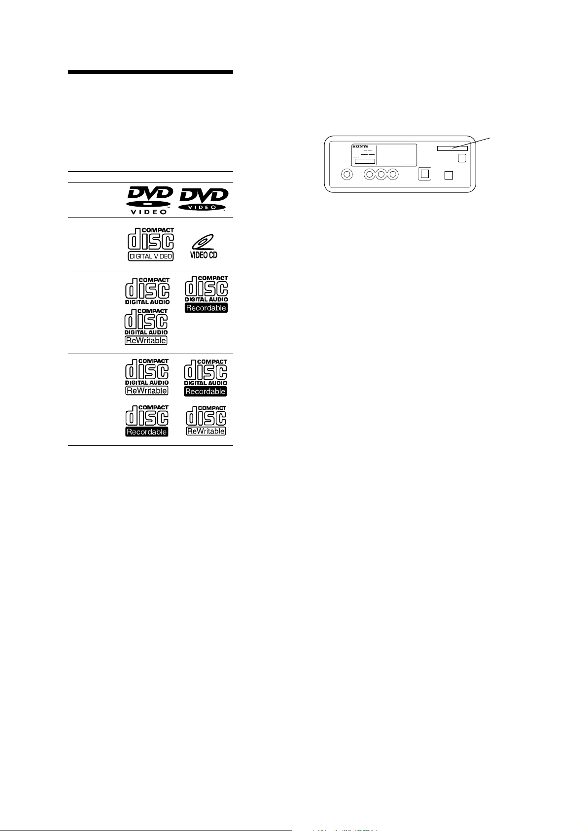
About discs this player can
play
This player can play 12 cm (4 7/10 in) disc only.
•DVD
•Video CD
•Audio CD
•CD-R/CD-RW
Disc type Label on the disc
DVD Videos
Video CDs
Audio CDs
SER VICING NOTES
For E model NTSC type and PAL type.
The type of an NTSC system and the type of a P AL system exist in
E model.
Please refer to the following figure about how to recognize.
– BACK VIEW –
MODEL NO.
DVD PLAYER
DC:12
MV-101
Ver 1.2
NTSC: NTSC TYPE
PAL: PAL TYPE
X
MP3 files
Notes on CD-Rs (recordable CDs)/
CD-RWs (rewritable CDs)
•Some CD-Rs/CD-RWs (depending on the
equipment used for its recording or the
condition of the disc) may not play on this
unit.
•You cannot play a CD-R/CD-RW that is not
finalized*.
•You can play MP3 files recorded on CDROMs, CD-Rs, and CD-RWs.
* A process necessary for a recorded CD-R/CD-RW
disc to be played on the audio CD player. Notes
on CD-Rs (recordable CDs)/CD-RWs (rewritable
CDs)
3
MV-101
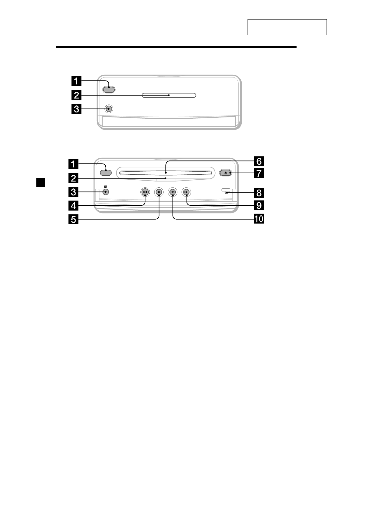
Location of controls
SECTION 1
GENERAL
This section is extracted from
instruction manual.
POWER
POWER
1 POWER (on/off) button*
To turn on/off the player, press and hold
the POWER button until the green light of
the button is turned on/off.
2 DISC IN light
When a disc is in the player, the DISC IN
light glows orange.
3 Receptor for the card remote
commander
4 u (play/pause) button
5 x (stop) button
6 Disc slot
7 Z (eject) button
Available to eject a disc from the player
even when the player is turned off.
8 RESET button
9 > (next) button
q; . (previous) button
DISC IN
MV-101
DISC IN
RESET
MV-101
* Warning when installing in a car
without an ACC (accessory) position
on the ignition key switch
Be sure to press and hold the POWER
button (1) on the player until the green
light of the button is turned off.
Otherwise, the player is not turned off and
this causes battery drain.
Note
Even when the player is turned off, you can eject a
disc from the player, though you cannot insert a
disc.
4
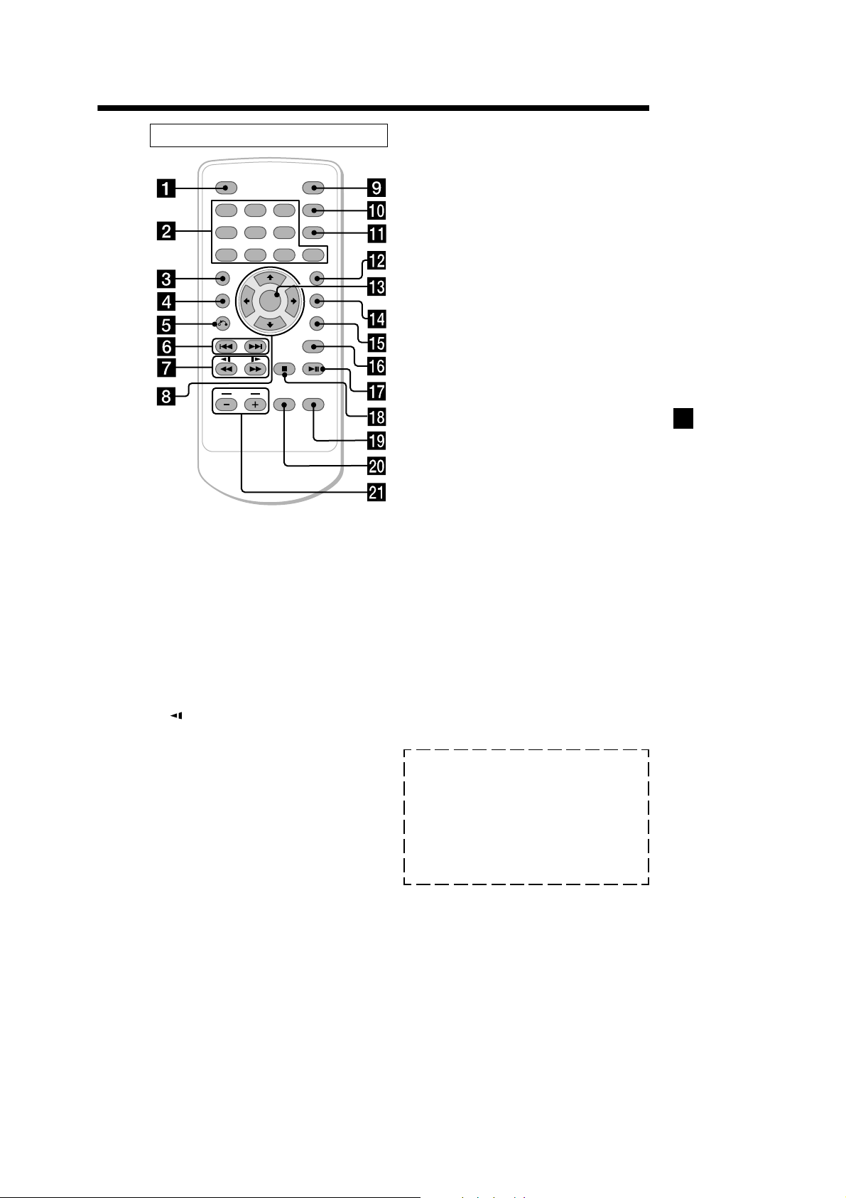
Card remote commander RM-X135
MV-101
ENTER
INPUT
POWER
SEARCH
CLEAR
SUBTITLE
ANGLE
AUDIO
SETUP
MONITOR
POWER
DISPLAY
123
456
7 890
TOP MENU
MENU
VOL
Refer to the pages listed for details.
1 DISPLAY button
To display a running time.
2 Number buttons
3 TOP MENU button
To display the top menu of a recorded
DVD or to turn on/off the PBC (Playback
control) menu of a Video CD.
4 MENU button
To display the recorded DVD menu.
5 O (return) button
6 ./> (previous/next) buttons
7
/m (fast/slow reverse)/
M/y (fast/slow forward) buttons
8 M/,/m/< buttons
9 POWER (on/off) button
For details, refer to “Cautions about the
POWER (on/off) button (9).“
q; SEARCH button
To specify a desired point on a disc by
chapter, title, or track.
qa CLEAR button
The corresponding buttons of the card
remote commander control the same
functions as those on the player.
Instructions in this manual describe how to use
the player by mainly using the card remote
commander.
Tip
Refer to “Replacing the lithium battery” for details
on how to replace the battery.
Cautions about the POWER (on/off) button (9)
• To turn off the player, press and hold the POWER
button for more than 2 seconds. The player is
completely turned off. If your car has no ACC
position, make sure that the green light of the
POWER button (1) on the player is
turned off. Otherwise it may cause battery drain.
• To turn on the player again, be sure to press and
hold the POWER button (1) on the
player until the green light of the button is
turned on.
qs SUBTITLE button
To change the subtitle language while
playing a DVD
qd ENTER button
To enter a setting.
qf ANGLE button
To select the multiple angles of view while
playing or pausing a DVD.
qg AUDIO button
To change the audio output/audio
language.
qh SETUP buttons
To enter or quit the setup menu.
qj u (play/pause) button
qk x (stop) button
ql MONITOR POWER (on/off) button*
To turn on/off the monitor.
w; INPUT button*
To select the input source.
wa VOL (–/+) buttons*
To turn up or down the volume.
* These buttons work for optional Sony monitors
other than XVM-R75 and XVM-H6.
5
MV-101
1
*
2
2
*
3
*
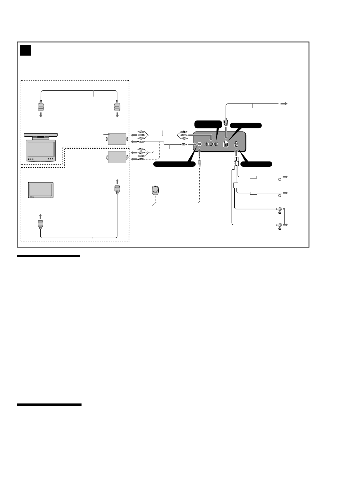
XVM-R70
Remote signal cord with stereo mini jacks: (5m) (supplied with a Sony monitor)
connects the player MV-101 and a connection box of an optional Sony monitor.
(However, this connection is not available for XVM-R75)
Remote control sensor7with a stereo mini jack (5m) (supplied with MV-101)
Connect the remote control sensor
monitor other than Sony product is connected.
There is an R (audio right )/L (audio left)/V (video) output on MV-101, so you can connect either XVMR70 or XVM-H65.
Monitor cable (supplied with XVM-R70)
7
to the player MV-101 when XVM-R75, XVM-H6, or an optional
Optical cable (not supplied)
to AV input
Connection box XA-115
(supplied with XVM-R70)
Connection box XA-113
(supplied with XVM-H65)
XVM-H65
to AV input
Monitor cable (supplied with XVM-H65)
Caution
• This unit is designed for negative ground 12 V
DC operation only.
• Before making connections, turn the car ignition
off to avoid short circuits.
• Connect the yellow and red power input leads
only after all other leads have been connected.
• Be sure to connect the red power input lead to
the positive 12 V power terminal which is
powered when the ignition switch is in the
accessory position.
• Run all ground wires to a common ground
point.
• The use of optical instruments with this product
will increase eye hazard.
• Use of controls adjustments or performance of
procedures of other than those specified herein
may result in hazardous radiation exposure.
Not es on the po wer supply cord (yellow)
•When connecting the player in combination with
other stereo components, the connected car
circuit’s rating must be higher than the sum of
each component’s fuse.
•When no car circuits are rated high enough,
connect the unit directly to the battery.
Not es on inst allation
• Before installation, be sure to turn the ignition
switch to the OFF position or take the key out.
Installing the player and the monitor (not
supplied) with the ignition on may cause battery
drain or a short circuit.
• Do not damage any pipes, tubes, the fuel tank or
electric wiring when installing the player and the
monitor (not supplied). This can cause a fire. If
you drill a hole in car panels, make sure that any
hidden car parts will not be damaged.
• Do not use any nuts or bolts for safety devices
such as steering linkage, fuel supply or braking
systems. This can cause a fire or an accident.
• Take care to prevent cords and wires from
getting tangled or crimped in the moving portion
of a seat rail.
to AV output
to AV output
6
3
*
3
*
1
*
REMOTE SIGNAL INPUT
Remote control sensor
2
7*
REMOTE SIGNAL INPUT
R/L/V
OUT
RL
V
OUTPUT OPTICAL OUTPUT POWER 12V
5
OPTICAL OUTPUT
POWER 12V
5 m
1A
5 m
5A
1 m
1 m
red
yellow
black
black
3
2
1
Connection diagram (2)
1
to a metal surface on the car
First connect the black ground lead, then connect
the yellow and red power input leads.
2
to the +12 V power terminal which is energized
at all times
Be sure to connect the black ground lead to a metal
surface of the car first.
3
to the +12 V power terminal which is energized
when the ignition switch is in the accessory
position
Be sure to connect the black ground lead to a metal
surface of the car first.
6
MV-101
3
4
2
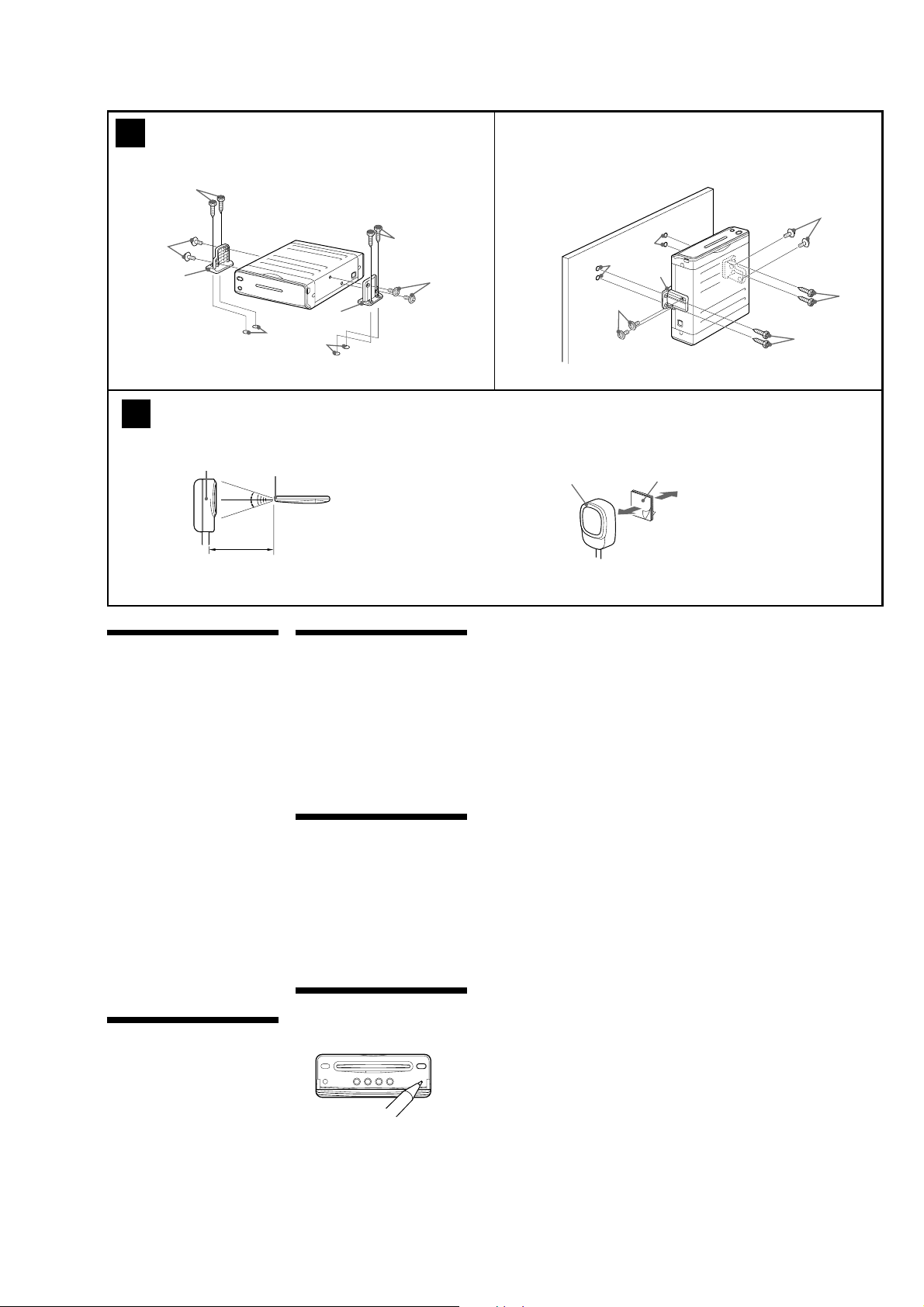
A
Horizontal installation
3
1
ø 3 mm
Light sensor
15º
15º
Almost 3 m (9.8 ft)
Light sensor
Wireless remote commander
B
Vertical installation
2
3
2
1
Remote control sensor
2
ø 3 mm
1
3
3
4
c
Precautions
•Choose the mounting location carefully.
•Avoid installing the player in places:
— subject to temperatures below – 30 °C (– 22
°F) or above 45 °C (113 °F)
— subject to direct sunlight.
— subject to heat;
Keep all products away from nearby hot
vehicle components that heat up over time
such as hoses, high current wires, and
braking system components. Make sure to
leave enough room for ventilation of
openings and slots to protect from over
heating.
— near heat sources such as heaters.
— exposed to rain or moisture.
— exposed to excessive dust or dirt.
— subject to excessive vibration.
— where the fuel tank might be damaged by
the tapping screws.
— where wire harnesses or pipes might be
under the place.
— where the screws or the player itself might
damage the spare tire, tools, or other
equipment in or under the trunk.
— where the player might interfere with with
the normal movements of the driver.
— under the floor carpet, as the heat
dissipation from the player might damage
the carpet.
•Be sure to use only the supplied mounting
hardware for a safe and secure installation.
•Use only the supplied screws.
•Make holes of ø 3 mm (
making sure there is nothing on the other side
of the mounting surface.
•Do not install the player on inclined places.
Install the player on a level surface.
•Install the player just horizontally or vertically.
1
/
8
in) only after
How to install the player (3)
When installing the player, choose the mounting
location carefully.
1
Place the player where you plan to install
it.
2
Mark the 4 positions for the holes of the
3
on the surface of the mounting
screws
board (not supplied).
The supplied mounting screws 3 are 15 mm
19
(
/32 in) long, so make sure that the mounting
board is thicker than 15 mm (
3
Drill the 4 positions to make the holes of ø
1
/
32
in) in diameter.
3 mm (
4
Mount the player on the board (not
supplied) with the parts
2
screws of
and 3.
19
/32 in).
1
and mounting
Remote control sensor (4)
Before installing the remote control sensor,
make sure the maximum signal distance of
remote control. The remote control can be used
up to approximately 3 m (9.8 ft) from the light
sensor, in a conical area spreading roughly 15º
from the light sensor.
For your saf et y
After installing the remote control sensor, be
sure to use the cord cramp (not supplied) to
secure up the cord onto the passenger seat side,
as it may interfere with the normal driving
operation. It is very dangerous for the cord to
get tangled with the gearshift lever during
driving.
Warning when installing in a car
without ACC (accessory)
position on the ignition key
switch
Aft er turning off the igniti on, be sure to
press and hold the POWER button on the
card remote commandar for more than 2
seconds. Make sure that t he green li ght of
the POWER button on the player is turned
off.
Otherwise, the player is not turned off and this
causes battery drain.
RESET button
When the installation and connections are
completed, be sure to open the front panel, then
press the RESET button with a ball-point pen,
etc.
7
MV-101
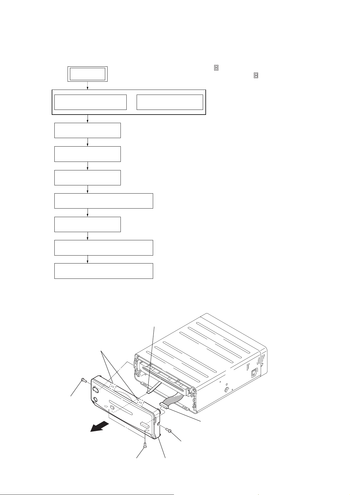
• This set can be disassembled in the order shown below.
2-1. DISASSEMBLY FLOW
SET
SECTION 2
DISASSEMBLY
Note 1: The process described in can be performed in any order.
Note 2: Without completing the process described in ,
the next process can not be performed.
2-2. CABINET FRONT ASSY
(Page 8)
2-4. CASE (UPPER)
(Page 9)
2-5. DVD MD ASSY
(Page 10)
2-6. CHASSIS (MD) ASSY
(Page 10)
2-7. SERVO BOARD, MECHANISM DECK
(Page 11)
2-8. TD-S-TOP-COVER
(Page 11)
2-9. LOADING MECHANISM ASSY
(Page 12)
2-10. TRAVERSE MECHANISM ASSY
(Page 12)
2-3. CABINET (REAR)
(Page 9)
Note: Follow the disassembly procedure in the numerical order given.
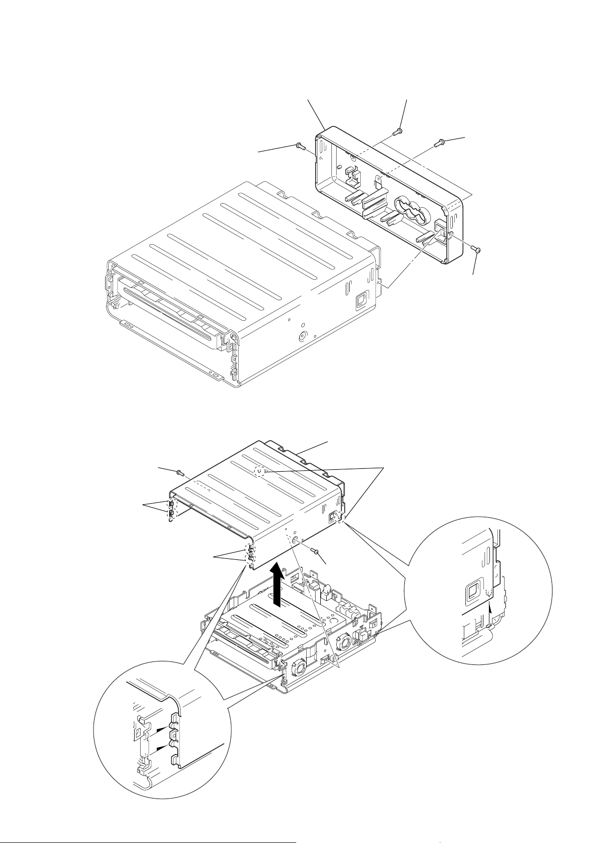
2-2. CABINET FRONT ASSY
6
key flexible board
(CN102)
4
two claws
3
screw
(+B2.6 × 6)
5
1
two screws
(+K2.6 × 6)
2
screw
(+B2.6 × 6)
8
cabinet front assy
7
connector (CN101)
8
MV-101
2-3. CABINET (REAR)
1
screw
(+B2.6 × 6)
5
cabinet (rear)
3
two screws
(+B2.6 × 6)
4
screw
(+BTP3 × 6)
2
screw
(+B2.6 × 6)
2-4. CASE (UPPER)
2
screw
×
6)
5
4
two bosses
(+B2.6
two bosses
6
case (upper)
1
screw
(+B2.6
3
two bosses
×
6)
9
MV-101
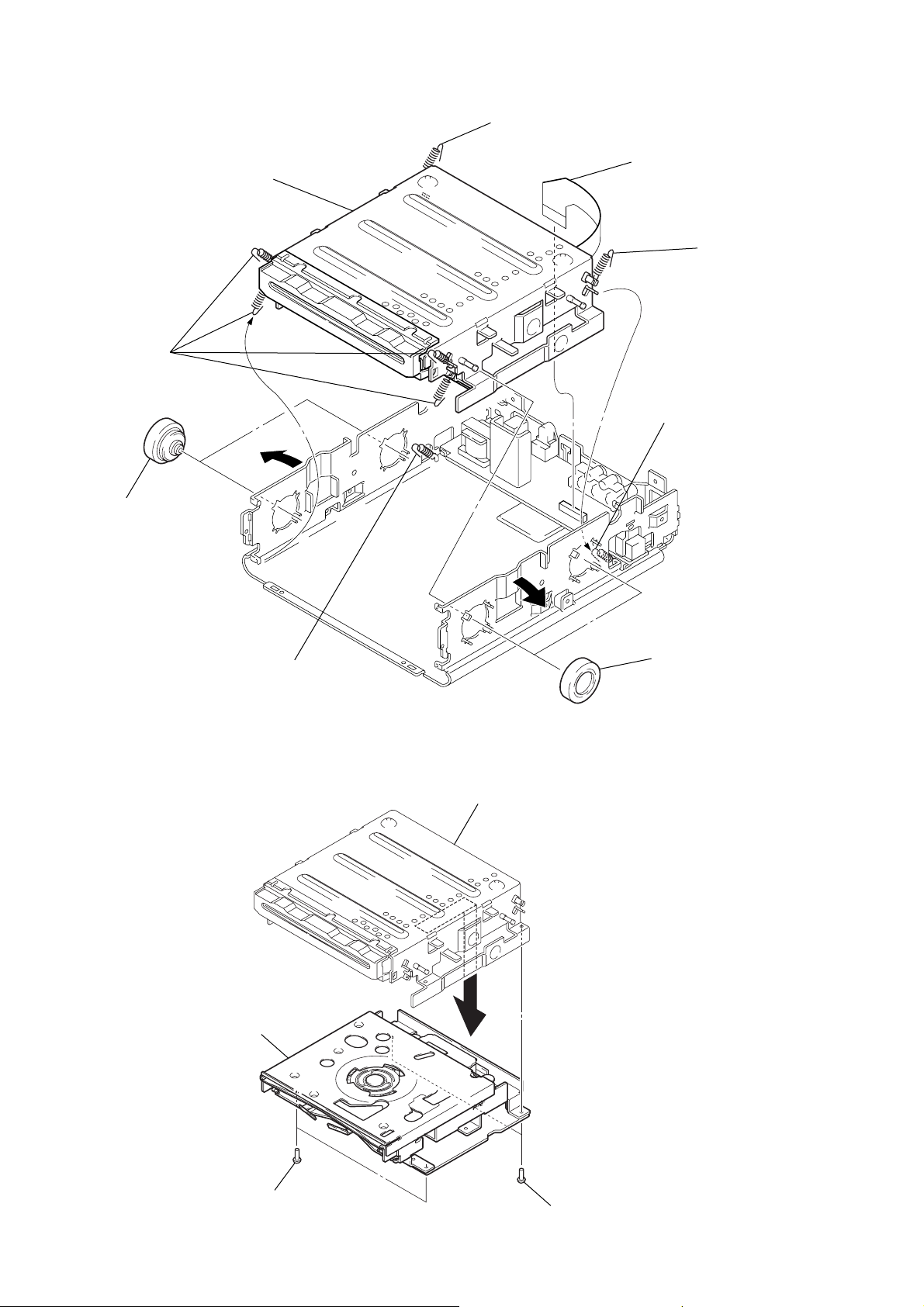
s
2-5. DVD MD ASSY
9
4
four tension spring
(MD) B/D
2
two dampers (S)
DVD MD assy
5
tension spring
(MD) C
1
power flexible board
(CN2)
6
7
tension spring
(MD) A
tension spring
(MD) C
2-6. CHASSIS (MD) ASSY
3
dvd unit
8
tension spring
(MD) A
4
chassis (MD) assy
3
two dampers (S)
10
2
two screws
(+B3
×
8)
1
two screw
(+B3 × 8)
 Loading...