

Page 1

MULTI-FORMAT STREAM BRIDGE
MSB-2000
OPERATION MANUAL
2nd Edition
Version 1.30
[English]
Page 2

WARNING
To prevent fire or shock hazard, do not
expose the unit to rain or moisture.
To avoid electrical shock, do not open the
cabinet. Refer servicing to qualified
personnel only.
WARNING: THIS WARNING IS APPLICABLE FOR USA
ONLY.
If used in USA, use the UL LISTED power cord
specified below.
DO NOT USE ANY OTHER POWER CORD.
Plug Cap Parallel blade with ground pin
(NEMA 5-15P Configuration)
Cord Type SJT, three 16 or 18 AWG
wires
Length Less than 2.5 m (8 ft. 3 in.)
Rating Minimum 10A, 125 V
THIS APPARATUS MUST BE EARTHED.
AVERTISSEMENT
Afin d’éviter tout risque d’incendie ou
d’électrocution, ne pas exposer cet appareil à
la pluie ou à l’humidité.
Afin d’écarter tout risque d’électrocution,
garder le coffret fermé. Ne confier l’entretien
de l’appareil qu’à un personnel qualifié.
CET APPAREIL DOIT ÊTRE RELIÉ À LA
TERRE.
VORSICHT
Um Feuergefahr und die Gefahr eines
elektrischen Schlages zu vermeiden, darf das
Gerät weder Regen noch Feuchtigkeit
ausgesetzt werden.
Um einen elektrischen Schlag zu vermeiden,
darf das Gehäuse nicht geöffnet werden.
Überlassen Sie Wartungsarbeiten stets nur
qualifiziertem Fachpersonal.
DIESES GERÄT MUSS GEERDET WERDEN.
Using this unit at a voltage other than 120 V
may require the use of a different line cord or
attachment plug, or both. To reduce the risk of
fire or electric shock, refer servicing to
qualified service personnel.
WARNING: THIS WARNING IS APPLICABLE FOR
OTHER COUNTRIES.
1. Use the approved Power Cord (3-core mains lead)/
Appliance Connector/Plug with earthing-contacts that
conforms to the safety regulations of each country if
applicable.
2. Use the Power Cord (3-core mains lead)/Appliance
Connector/Plug conforming to the proper ratings (Voltage,
Ampere).
If you have questions on the use of the above Power Cord/
Appliance Connector/Plug, please consult qualified service
personnel.
AVERTISSEMENT:
1. Utiliser le cordon d’alimentation approuvé (conducteur à
trois noyaux)/connecteur pour appareils approuvé / fiche
avec contacts de mise à la terre approuvée, qui est
conforme aux règles de sécurité de chaque pays, si
applicable.
2. Utiliser un cordon d’alimentation (conducteur à trois
noyaux)/connecteur pour appareils/fiche avec contacts de
mise à la terre conforme aux valeurs nominales correctes
(tension, ampérage).
Pour toute question concernant l’emploi du cordon
d’alimentation/connecteur pour appareils/fiche ci-dessus,
consulter un agent de service compétent.
WARNUNG:
1. Es ist ein (dreiadriges) Netzkabel/Netzstecker mit
Erdungskontakt zu verwenden, der den
Sicherheitsbestimmungen vor Ort entspricht.
2. Es ist ein (dreiadriges) Netzkabel/Netzstecker mit
ausreichenden Anschlußwerten (Spannung/Strom) zu
verwenden.
Bei Fragen zum Gebrauch des obigen Netzkabels/
Netzsteckers wenden Sie sich bitte an den technischen
Kundendienst.
When using a LAN cable: For safety, do not connect to the
connector for peripheral device wiring that might have
excessive voltage.
2
Page 3

For the customers in the USA
This equipment has been tested and found to comply with
the limits for a Class A digital device, pursuant to Part 15 of
the FCC Rules. These limits are designed to provide
reasonable protection against harmful interference when the
equipment is operated in a commercial environment. This
equipment generates, uses, and can radiate radio
frequency energy and, if not installed and used in
accordance with the instruction manual, may cause harmful
interference to radio communications. Operation of this
equipment in a residential area is likely to cause harmful
interference in which case the user will be required to correct
the interference at his own expense.
You are cautioned that any changes or modifications not
expressly approved in this manual could void your authority
to operate this equipment.
The shielded interface cable recommended in this manual
must be used with this equipment in order to comply with
the limits for a digital device pursuant to Subpart B of Part 15
of FCC Rules.
For the customers in Europe
This product with the CE marking complies with both the
EMC Directive (89/336/EEC) and the Low Voltage Directive
(73/23/EEC) issued by the Commission of the European
Community.
Compliance with these directives implies conformity to the
following European standards:
• EN60950: Product Safety
• EN55103-1: Electromagnetic Interference (Emission)
• EN55103-2: Electromagnetic Susceptibility (Immunity)
This product is intended for use in the following
Electromagnetic Environment(s):
E1 (residential), E2 (commercial and light industrial), E3
(urban outdoors) and E4 (controlled EMC environment, ex.
TV studio).
Pour les clients européens
Ce produit portant la marque CE est conforme à la fois à la
Directive sur la compatibilité électromagnétique (EMC) (89/
336/CEE) et à la Directive sur les basses tensions (73/23/
CEE) émises par la Commission de la Communauté
Européenne.
La conformité à ces directives implique la conformité aux
normes européennes suivantes:
• EN60950: Sécurité des produits
• EN55103-1: Interférences électromagnétiques (émission)
• EN55103-2: Sensibilité électromagnétique (immunité)
Ce produit est prévu pour être utilisé dans les
environnements électromagnétiques suivants:
E1 (résidentiel), E2 (commercial et industrie légère), E3
(urbain extérieur) et E4 (environnement EMC contrôlé ex.
studio de télévision).
Für Kunden in Europa
Dieses Produkt besitzt die CE-Kennzeichnung und erfüllt
sowohl die EMV-Direktive (89/336/EEC) als auch die
Direktive Niederspannung (73/23/EEC) der EG-Kommission.
Die Erfüllung dieser Direktiven bedeutet Konformität für die
folgenden Europäischen Normen:
• EN60950: Produktsicherheit
• EN55103-1: Elektromagnetische Interferenz (Emission)
• EN55103-2: Elektromagnetische Empfindlichkeit
(Immunität)
Dieses Produkt ist für den Einsatz unter folgenden
elektromagnetischen Bedingungen ausgelegt:
E1 (Wohnbereich), E2 (kommerzieller und in beschränktem
Maße industrieller Bereich), E3 (Stadtbereich im Freien) und
E4 (kontrollierter EMV-Bereich, z.B. Fernsehstudio).
3
Page 4

Table of Contents
Overview.....................................................................................................5
Features ................................................................................................5
Optional Accessories............................................................................5
Related Products...................................................................................6
Notes on Use ........................................................................................6
Names and Functions of Parts..................................................................7
Example System Configurations ............................................................11
Changing Settings Using the Front Panel .............................................13
On-Screen Display Overview..................................................................16
Changing Settings Using Telnet or RS-232C Terminals......................26
Changing Settings Using a Web Browser..............................................29
List of Menus............................................................................................36
Simple Network Management Protocol (SNMP)..................................89
SNMP Commands..............................................................................90
Private Management Information Base (MIB)...................................93
SNMP Traps ..................................................................................... 110
Specifications..........................................................................................111
4
Page 5

Names and Functions of Parts
Overview
The MSB-2000 Multi-Format Stream Bridge provides
SDI, SDTI-CP, DVB-ASI and 100Base-TX with
MSBA-20IP network adapter board, and is a stream
converter which performs MPEG2 encoding/decoding
(sdi_to_asi, sdti-cp _to_asi, asi_to_sdi, asi_to_sdti-cp,
tx-rx (sdi_to_asi/asi_to_sdi), tx-rx (cm)).
Features
Audio and video compression
The MSB-2000 has several encoding modes (IMX,
Normal, Normal BL, Low delay and so on) that
provide the best balance between the encoded picture
quality, the codec latency and the bit rate depending on
the particular manner of use.
The MSB-2000 has audio encoding and decoding to
MPEG1 Layer II Audio (four channels) and SMPTE
302M LPCM Audio (eight channels).
For more details, see the List of Menus (page 36).
Parameter referring re-encoding
Parameter referring re-encoding keeps up the superb
MPEG picture quality at mutual conversions between
Long GOP and Short GOP (All I CBG (IMX)). It can
minimize generation loss when reiterating GOP
conversions by using the history data.
Simultaneous encoding/decoding function
In case of tx-rx (sdi_to_asi/asi_to_sdi) or tx-rx (cm)
mode, encoding and decoding can be carried out
simultaneously.
Operation control
The operator can control the MSB-2000 from the front
panel or through an HTTP, Telnet, or RS-232C
interface. The system incorporates a GUI which can be
accessed with an Internet browser without requiring
special-purpose control software, for unit setup and
VTR/disk recorder remote control via an RS422A
interface.
1)
VBI Transmission
The MSB-2000 (TX side) transmits VITC, closed
caption (available only in a 525 video system), UMID
and uncompressed data in the VBI information of SDI
input video as private data.
Resume function
The resume function preserves mode settings after a
power off, allowing the system to be started up after
power on with the saved settings.
Fitted with alarm contact output
If an error occurs in the MSB-2000, in addition to the
alarm indicator on the unit, both SNMP and relay
contact outputs are available.
Self-diagnosis function
The self-diagnosis function operates when the unit is
powered on, and the self-diagnosis information (log
message) is output on the Telnet and RS-232C
interfaces and SNMP.
Optional Accessories
MSBA-20IP network adapter board
This network adapter board, installed in the unit,
provides UDP/IP based bidirectional realtime material
transfer by RTP (realtime transport protocol).
Maintenance manual
This manual contains the information needed for
servicing at the main component level (error messages,
service parts list, overall block diagram and so on.)
Power cord
This connects the AC power inlet on the rear panel of
the unit to a power source.
RMM-30 Rack Mount Rail
Consists of slide rails to mount this unit in a 19-inch
standard rack.
1)
Network monitoring function
The system supports SNMP (Simple Network
Management Protocol) used in the telecommunications
industry for network monitoring/control.
.........................................................................................................................................................................................................
1) Not supported by Versions 1.30.
5
Page 6

Overview
Related Products
BDX-D1000 MPEG Decoder Unit
BDX-N1000 ATM Network Interface Unit
Notes on Use
Use this unit within the following limitations:
•The bit rate for video data the MSB-2000 can encode
or decode is 15 Mbps at maximum with MPEG 2
MP@ML and 50 Mbps at maximum with MPEG 2
4:2:2P@ML. Note, however, that ts_rate is 35 Mbps
or less with MSBA-20IP.
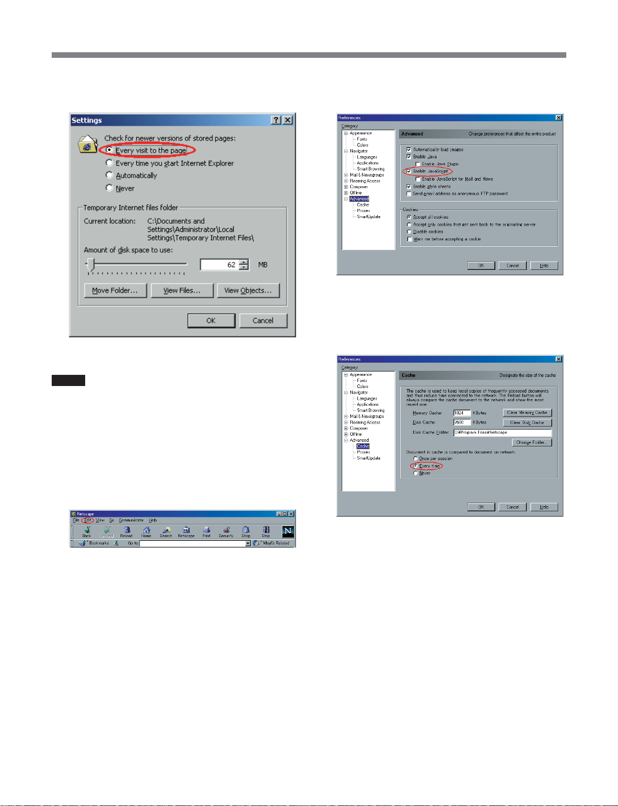
•Note that performance cannot be guaranteed if there
is a large amount of jitter on the input signal.
•When using the MSBA-20IP for MPEG stream
transfer, transfer bandwidth must be ensured, for
example by setting the VLAN (Virtual LAN) on the
LAN Switch side.
•When using this unit with video_encmode set to
“LD”, and connected to a BDX-D1000, set
seq_hdr_cycle to “interstitial”, and use the factory
default settings for pat_interval, pmt_interval, and
pcr_interval.
6
Page 7
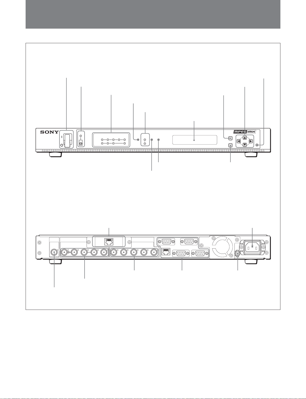
Names and Functions of Parts
Names and Functions of Parts
Front panel
Rear panel
1 POWER switch
2 PANEL INHI indicator and selector switch
PANEL
POWER
INHI
3 IN/OUT indicators
SDTI
SDI ASI
IN
OUT
ASI
CASCADE
4 REF IN indicator
5 VIDEO SYSTEM 525/625 indicators
REFINVIDEO
OPTION
SYSTEM
LAN ALARM
525
625
7 ALARM indicator
6 LAN indicator
9 MENU button
8 Display window
MULTI-FORMAT STREAM BRIDGE MSB-2000
qs RESET button
qa Cursor keys
MENU
ENTER
RESET
0 ENTER button
a)
REF IN INPUT OUTPUT
SDI/SDTI BIT STREAM CASCADE 1 2SDI/SDTI 1 2
DVB ASI MON OUT DVB ASI
RTP
SDI
MON
(SUPER)
BIT STREAM
DVB ASI
3 OUTPUT
2 INPUT connectors
connectors
1 REF IN connector
a) The rear panel is shown with an optional MSBA-20IP installed.
REMOTE1 REMOTE2
10BASE-T
RS-232C ALARM
4 CONTROL I/O
connectors
CONTROL
I/O
6 - AC IN connector7 Option panel
- AC IN
U
5 U (signal ground)
connector
7
Page 8

Names and Functions of Parts
Front panel
1 POWER switch
This powers the unit on or off. When the “ ` ” side of
the switch is pressed the power is on, and when the
aa
“
a” side is pressed the power is off.
aa
2 PANEL INHI (panel inhibit) indicator and
selector switch
To disable the MENU button, ENTER button, and
cursor keys (v, V, b, B), slide this switch up. (The
indicator lights amber.)
3 IN/OUT indicators
The indicators light or flash green corresponding to the
input/output signals selected in the “B:mode” menu.
IN indicator lit (green): The input signal selected in
the “B:mode” menu is detected.
IN indicator flashing (green): The input signal
selected in the “B:mode” menu is not detected.
OUT indicator lit (green): Selected in the “B:mode”
menu.
Note
When the MSBA-20IP is installed, the validity of the
OPTION IN/OUT indicators depends on the settings in
the “B:mode” menu and menu items “E001:rtp_tx”
and “E021:rtp_rx”. Note that when a destination is not
found, the OPTION OUT indicator flashes.
For more details of the menus, see the List of Menus (page
36).
4 REF IN (reference input) indicator
Lit (green): In the menu item
“C002:frame_sync_ref,” ref_in is selected, and a
composite [video] signal such as black burst is
connected to the REF IN connector.
Flashing (green): In the menu item
“C002:frame_sync_ref,” ref_in is selected, but a
composite [video] signal such as black burst is not
connected to the REF IN connector.
Note
To the REF IN connector, connect a signal such as
black burst whose amplitude does not fluctuate.
5 VIDEO SYSTEM 525/625 indicators
525 indicator lit (green): In the menu item
“M001:video_system” 525-line format is selected.
625 indicator lit (green): In the menu item
“M001:video_system” 625-line format is selected.
For more details of the menus, see the List of Menus (page
36).
6 LAN indicator
Lit (green): The unit is connected to the LAN
(10BASE-T).
Flashing (green): The unit is connected to the LAN
(10BASE-T), and data is being transmitted.
7 ALARM indicator
If a problem is detected during operation, an alarm
signal is output from the ALARM connector on the
read panel, and this indicator lights red.
8 Display window
After powering on, an initial screen appears for about
2 seconds. Next, the STATUS screen appears.
Press the MENU button to display the menus and
setting confirmation screens.
For details of the display at power on, see the section
“Display when the unit is powered on” (page 13).
9 MENU button
Press the MENU button to light it, and show the menus
and setting confirmation screens in the display
window. Press once more to switch to the STATUS
screen, and turn the button off.
At the point of confirming a setting, to cancel the
change, press the MENU button to return to the
previous settings.
For more details of the menus, see the List of Menus (page
36).
0 ENTER button
When a setting is shown in the display window, press
this button to select or confirm it.
When menu operations are enabled on the monitor
screen, this also confirms the selection of an input
program.
For more details of the menus, see the List of Menus (page
36).
8
Page 9

Names and Functions of Parts
qa Cursor keys (vVbB)
In the menu display, press the v and V keys to select
an item.
In the menu display, press the b and B keys to move
through the menu levels.
When a setting value is an IP address or other value
that you enter directly, use the b and B keys to select
a digit, and the v and V keys to change the numeric
3 OUTPUT connectors
SDI/SDTI (serial digital interface/serial data
transport interface output) 1, 2 connectors
(BNC type): These output SDTI-CP format
digital video/audio signals.
SDI MON (serial digital interface monitor output)
(SUPER) connector (BNC type): This outputs an
SDI signal for a monitor.
value.
The v, V,b and B keys have an auto-repeat mode
when held down.
When menu operations are enabled on the monitor
screen, press the v and V keys to select a submenu.
Press the b and B keys to select an input program.
qs RESET button
This resets the unit. Use a sharp object to press the
recessed button.
The on-screen display can be enabled by a menu
setting. For more details, see “On-Screen Display
Overview” (page 16) and “List of Menus” (page 36).
Notes
•If the menu item “C021” is set to “LPCM” and
“C026” to “1-8” when “sdi_to_asi” or “sdticp_to_asi” is selected in the “B:mode” menu,
then no audio is output from the SDI/SDTI and
SDI MON (SUPER) connectors.
•If the menu item “C004:monitor_select” is set to
Rear panel
“tx” when “tx-rx” is selected in the “B:mode”
menu, then no audio is output from the SDI
1 REF IN (reference input) connector (BNC type)
Input a reference video signal from an external device.
MON (SUPER) connector.
•If “tx-rx (cm)” is selected in the “B:mode” menu,
neither video nor audio is output from the SDI
Note
To this connector, connect a signal such as black burst
whose amplitude does not fluctuate.
MON (SUPER) connector.
•The SDI MON (SUPER) connector does not
support EDH or VBI transmission. Depending on
the mode, it does not support video/audio output,
2 INPUT connectors
as described above.
SDI/SDTI (serial digital interface/serial data
transport interface input) connectors (BNC
type): The left connector is an input connector for
SDI/SDTI-CP format digital video/audio signals.
The right connector is an active through output,
which while the unit is powered on outputs a
BIT STREAM DVB ASI 1, 2 connectors (BNC
type): These are MPEG2 serial bit stream output
connectors. This allows DVB serial (DVB-ASI
standard compliant (DVB A010 compliant))
format transport output.
wave-shaped copy of the signal input to the left
connector.
BIT STREAM DVB ASI connector (BNC type):
This is an MPEG2 serial bit stream input
connector. This allows DVB serial (DVB-ASI
standard compliant (DVB A010 compliant))
format transport input.
BIT STREAM MON OUT (bit stream monitor
4 CONTROL I/O (control input/output)
connectors
REMOTE1 connector/REMOTE2 connector (D-
sub 9-pin, RS-422A standard compliant,
female): Connect to the REMOTE connector of
an MSW-M2000/A2000/2000, Betacam VTR, or
similar, to enable remote control of the VTR.
output) connector (BNC type): While the unit is
powered on, a wave-shaped copy of the signal
input to the BIT STREAM DVB ASI connector is
output.
CASCADE DVB ASI connector (BNC type): Not
currently used.
.........................................................................................................................................................................................................
1) Ethernet is a registered trademark of Xerox Corporation.
For more details, see “Changing Settings Using a Web
Browser” (page 29).
Note
The maximum guaranteed cable length for the
REMOTE1/REMOTE2 connector is 200 m.
9
Page 10

Names and Functions of Parts
10BASE-T connector (RJ-45 modular jack,
1)
Ethernet
IEEE802.3 compliant): This
connector is for network control from a host
computer.
RS-232C connector (D-sub 9-pin, RS-232C
standard compliant, male): This is a control and
maintenance connector. Connect to the RS-232C
connector on the control computer.
ALARM connector (D-sub 9-pin, female): When a
problem occurs, this outputs an alarm signal (relay
contact output).
The output consists of two types, designated major
alarm and minor alarm. Externally shorting pins 4
and 5 by changing internal DIP switch settings
causes a forced hardware reset.
For details, refer to the Installation Manual.
Note
To prevent inadvertent connection of a wrong
connector, it is recommended to keep this
protected by a safety cap.
5 U (signal ground) connector
This is signal ground. Connect to ground as required.
6 - AC IN connector
Connect to an AC power supply with the AC power
cord (sold separately).
7 Option panel
This allows an optional MSBA-20IP Network Adapter
Board to be installed.
10
Page 11
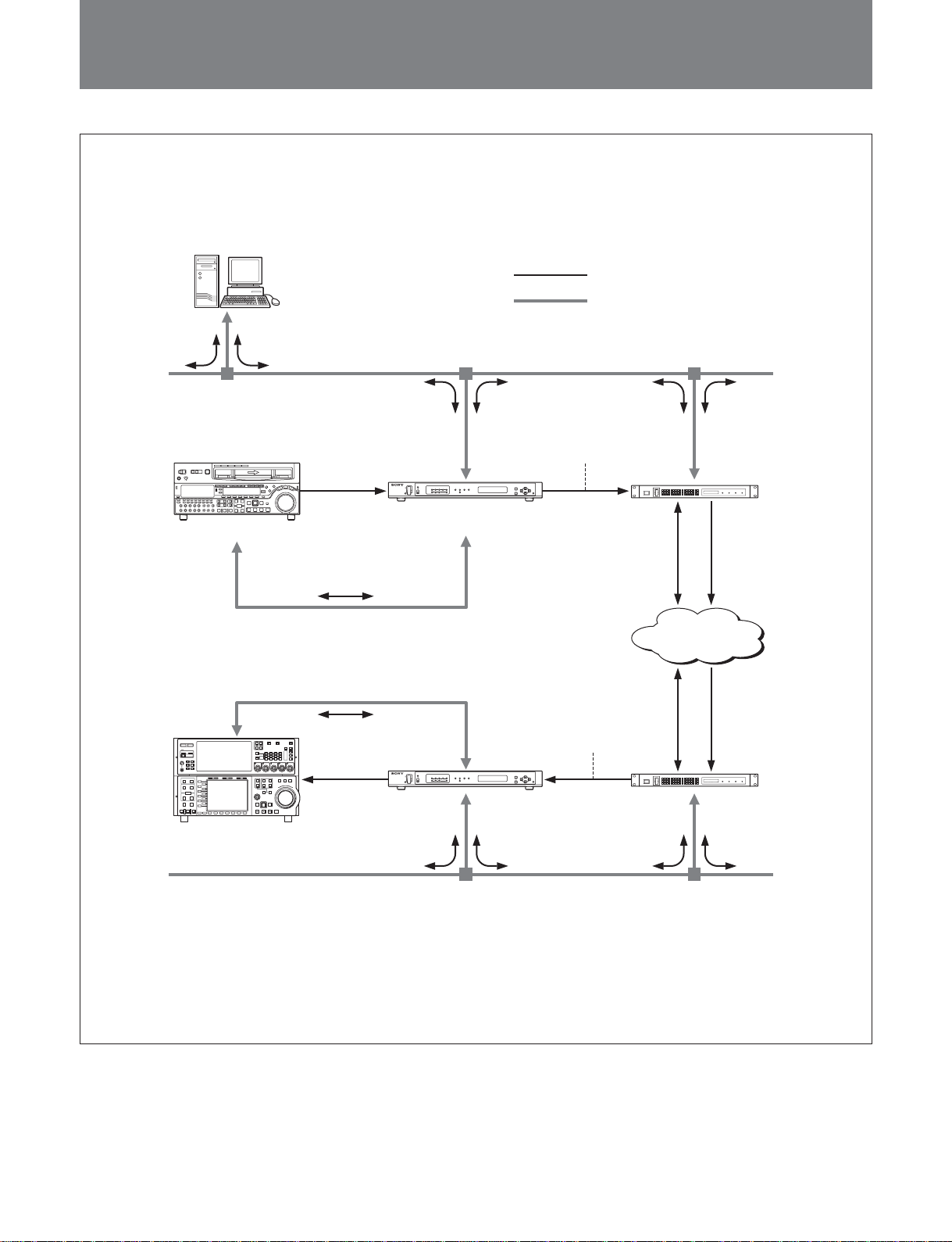
Names and Functions of Parts
Example System Configurations
MPEG Stream Transmission & Control vial a Telco’s Network
Host computer
(Control computer)
MSW-M2000/M2000P
SDTI-CP
RS422A
RS422A
SDTI-CP
Ethernet 10Base-T
MSB-2000
Video & Audio
Command & Status, etc.
DVB-ASI
ex. 20 Mb/s Long GOP
50 Mb/s All I-frame
NETWORK IF UNIT BDX-N1000
BDX-N1000
IP over ATM MPEG over ATM
ATM
MPEG over ATMIP over ATM
DVB-ASI
ex. 20 Mb/s Long GOP
50 Mb/s All I-frame
NETWORK IF UNIT BDX-N1000
MAV-555A
a) To be supported in near future.
MSB-2000
a)
Ethernet 10Base-T
BDX-N1000
11
Page 12
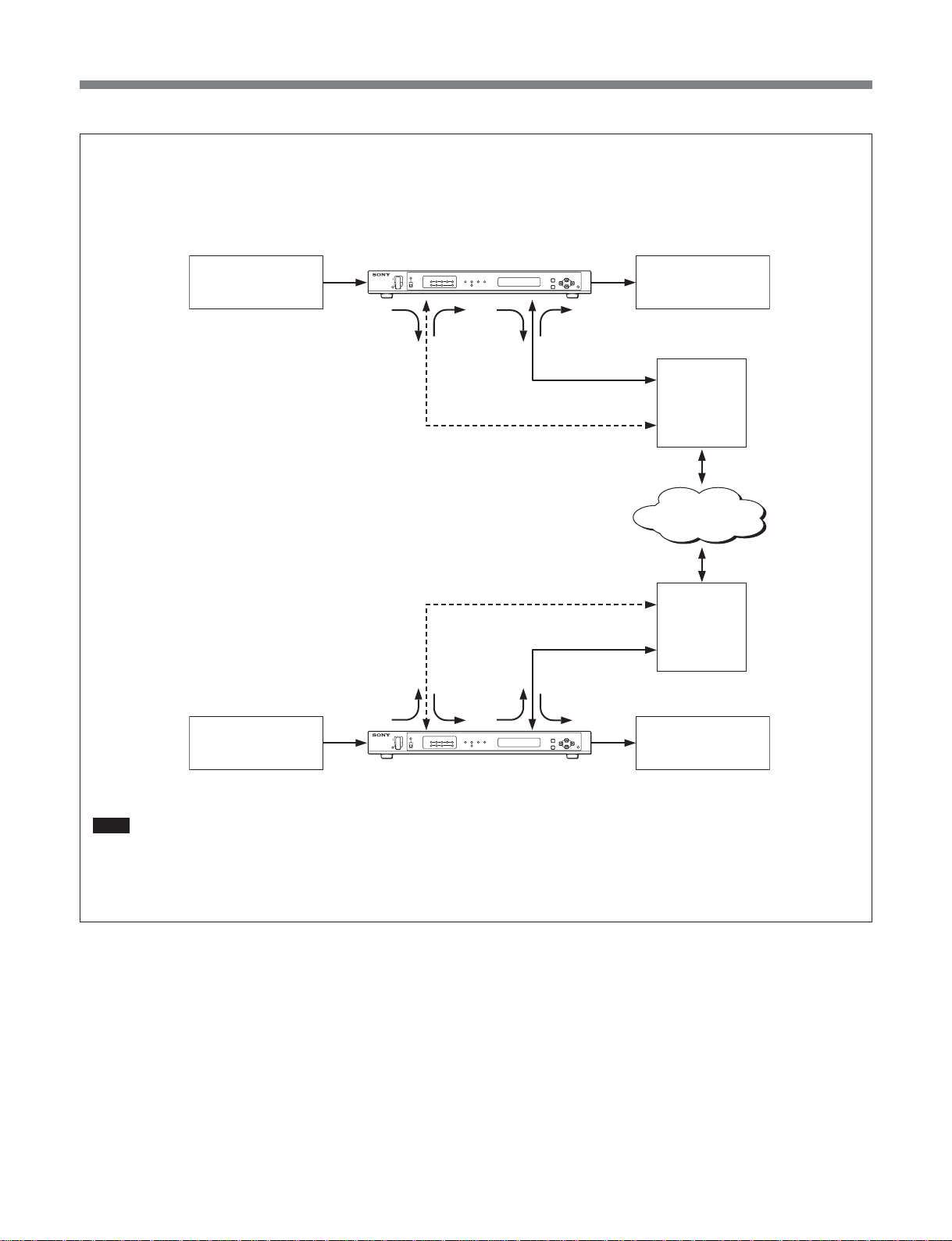
Example System Configurations
Stream Receive and Transmit
Simultaneous Tx/Rx (MSBA-20IP required)
SDI (B)
MSB-2000 with MSBA-20IP
SDI (A)
For MSB control
• Telnet
• Ftp
• Http
• SNMP...
Ethernet 10Base-T
For MSB control
• Telnet
• Ftp
• Http
• SNMP...
SDI (A) SDI (B)
MSB-2000 with MSBA-20IP
RTP MPEG TS
Streaming only
Ethernet 100BASE-TX
Ethernet 10Base-T
Ethernet 100Base-TX
RTP MPEG TS
Streaming only
IP router
Dedicated
IP router
IP router
Note
If “tx-rx” or “tx-rx (cm)”is selected in the “B:mode”menu so that the
bidirectional simultaneous transfer (simultaneous encoding/
decoding) function is enabled, note that only 4 channels at the
maximum of SDI Embedded Audio are supported.
12
Page 13
Changing Settings Using the Front Panel
Changing Settings Using the Front Panel
Display when the unit is powered on
When the unit is powered on, the display window
shows the message “Welcome to SONY MPEG
World!” for about two seconds (initial screen).
After about 2 seconds have elapsed, this changes to the
STATUS screen.
•Display for sdi_to_asi mode, tx-rx mode, tx-rx (cm)
mode, and sdti-cp_to_asi mode: “video_rate: nnn,
ts_rate: nnn”
•Display for asi_to_sdi mode and asi_to_sdti-cp mode:
“program_no = nnn”
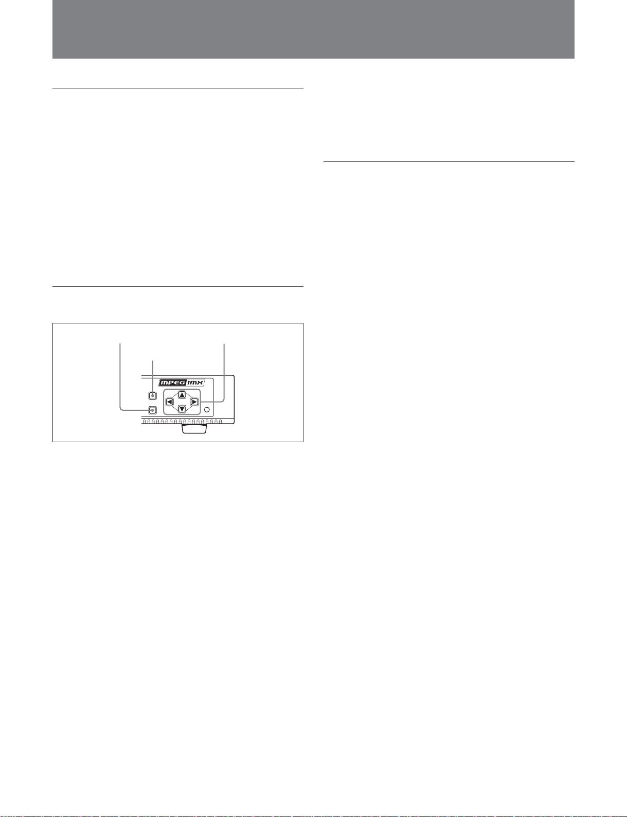
To change the mode setting
ENTER button
MENU button
MENU
ENTER
Cursor keys
RESET
6 Press the MENU button.
The MENU button goes off, and this exits the
menus.
To change ts_rate
1 Press the MENU button.
The MENU button lights, and the menu appears in
the display window.
2 Press the V key, to display “C:Setup.”
3 Press the B key.
4 With the v and V keys, display “C061:ts_rate.”
The lower part of the display window shows the
current setting value.
5 Press the ENTER button.
The “manual” indication and the ENTER button
flash.
1 Press the MENU button.
The MENU button lights, and the menu appears in
the display window.
2 Press the V key, to display the “B:mode” menu.
3 Press the ENTER button.
The ENTER button and the mode indication flash.
4 With the v or V key, select the mode. You can
also use the B and b keys.
5 Press the ENTER button.
The ENTER button goes off, and the unit is set to
the selected mode.
To cancel a change of mode setting
Without pressing the ENTER button, press the
MENU button.
6 With the v and V keys, select the setting value.
When “auto” is selected
1 Press the ENTER button.
The ENTER button goes off, and the setting
changes to an automatically calculated value for
ts_rate.
An “A” is appended after the setting value.
When “manual” is selected
1 Press the ENTER button.
The cursor flashes on the setting value.
2 Enter the setting value with the v and V keys.
To move from one digit to another use the B
and b keys.
You can specify ts_rate in increments of 1 kbps.
Parameter unit: Mbps
3 Press the ENTER button.
The ENTER button goes off, the setting is
changed, and “**” appears.
13
Page 14

Changing Settings Using the Front Panel
If the new setting of ts_rate is outside the
permitted range
An error message appears in the display window.
C061:ts_rate
error max=68Mbps
Press the MENU button or ENTER button, and
reenter the setting value.
For details of the setting range, see the List of Menus
(page 36).
To cancel a changed ts_rate
Without pressing the ENTER button, press the
MENU button.
To return all “C:Setup” settings to their values
before a change
1 With the v and V keys, display “C998:cancel.”
2 Press the ENTER button.
The “Execute” indication and ENTER button
flash.
3 Press the ENTER button.
The ENTER button goes off, and all setting
changes within “C:Setup” are canceled.
If an item number will not fit in the display
window, the B and b keys flash. Press a flashing
key to check the related item number.
After checking, return to step 1, and reenter the
setting value.
10
Press the ENTER button.
This executes the setting.
11
Press the MENU button.
The MENU button goes off, and this exits the
menus.
To change the IP address
1 Press the MENU button.
The MENU button lights, and the menu appears in
the display window.
2 Press the V key, to display “L:network.”
3 Press the B key.
7 After pressing the b key, with the v key display
“A:process.”
8 Press the ENTER button.
The “analyse” indication and ENTER button flash.
9 Press the ENTER button.
The “analyse OK start” indication and ENTER
button flash.
If a change in ts_rate causes errors in related
items
In the lower part of the display window the item
number causing the error appears.
A:process
C013,C021,C022,C023
4 With the v and V keys, display “L001:ip_addr.”
In the lower part of the display window , the
currently set IP address appears.
5 Press the ENTER button.
The cursor on the IP address and the ENTER
button flash.
6 Enter the setting value with the v and V keys.
To move from one digit to another use the B and
b keys.
7 Press the ENTER button.
The ENTER button goes off, and the IP address is
changed.
To cancel a change of IP address
Without pressing the ENTER button, press the
MENU button.
14
Page 15

Changing Settings Using the Front Panel
8 Press the MENU button.
The MENU button goes off, and this exits the
menus.
9 Power off the unit, and power on again.
The IP address change now takes effect.
Note
When changing the IP address, be sure to carry out
the step of powering off and on again.
To return the “C:Setup” settings to their
factory default values
1 Press the MENU button.
The MENU button lights, and the menu appears in
the display window.
To return all settings to their factory
default values
1 Press the MENU button.
The MENU button lights, the menu appears in the
display window.
2 Press the V key, to display “N:maintenance.”
3 Press the B key.
4 With the v and V keys, display “N999:init.”
5 Press the ENTER button.
The “Execute” indication flashes.
6 Press the ENTER button.
The ENTER button goes off, and the settings
return to their factory defaults.
2 Press the V key, to display “C:Setup.”
3 Press the B key.
4 With the v and V keys, display “C999:init.”
5 Press the ENTER button.
The “Execute” indication flashes.
6 Press the ENTER button.
The ENTER button goes off, and the settings
return to their factory defaults.
To cancel returning the settings to their factory
default values
Without pressing the ENTER button, press the
MENU button.
7 Press the MENU button.
The MENU button goes off, and this exits the
menus.
To cancel returning the settings to their factory
default values
Without pressing the ENTER button, press the
MENU button.
7 Press the MENU button.
The MENU button goes off, and this exits the
menus.
15
Page 16

On-Screen Display Overview
On-Screen Display Overview
With this unit, you can use the display on a monitor
screen connected to the SDI MON (SUPER) connector
to monitor information such as packet IDs, or to select
an input program.
The on-screen display (OSD) shows a main menu,
with a number of submenus, relevant information, and
an input program selection menu.
For menu operations, use the MENU button, ENTER
button, and cursor keys on this unit (see the illustration
on page 13).
Settings for OSD and operation
Use the following procedure.
1 Power on the monitor.
2 Press the MENU button.
The MENU button lights, and the menu appears in
the display window.
Submenus Relevant information
MSB-2000
MAIN MENU
-DECODER-
RX MONITOR
I/O STATUS
RX STATUS
-STREAM
-TIMING
-VIDEO
-AUDIO
DECODE STATUS
SYSTEM INFO.
v V
SELECT
INPUT PROGRAM SELECT
200 201 202 203
204 205 206
b B
SELECT
Input program
selection menu
RX MONITOR
PROGRAM NUMBER 200
VIDEO RATE 12.000 Mbps
AUDIO INDICATOR
CH1 PRESENT
CH2 PRESENT
CH3 ABSENT
CH4 ABSENT
CH5 ABSENT
CH6 ABSENT
CH7 ABSENT
CH8 ABSENT
7 Press the V key.
The menu item “S002:control” appears.
8 Press the ENTER button.
3 Press the V key, and display the “S:osd” menu.
4 Press the B key.
The menu item “S001:display” appears.
•When this is set to “off,” continue to step 5.
•When this is set to “on,” continue to step 7.
Note
In tx-rx (cm) mode, this menu item is always set to
“on.”
5 Press the ENTER button.
The “off” indication and the ENTER button flash.
6 Press the v key, to select the “on” setting, then
press the ENTER button.
The ENTER button goes off, and the OSD appears
on the monitor screen.
The content of the OSD depends on the operating
mode of the unit.
Using the buttons and cursor keys on this unit, you
can make submenu selections and input program
settings on the monitor.
To select a submenu
Press the V key or v key, to move the cursor to the
desired submenu.
The information for the selected submenu appears on
the right of the screen.
Note
The submenus can only be displayed; it is not possible
to change the settings.
To change the input program setting (INPUT
PROGRAM SELECT)
Press the b key or B key, to move the cursor to the
desired input program. While the cursor is moved, it
appears white.
When you press the ENTER button, the cursor shows
red and the desired input program is selected. At the
same time, the selected input program submenu
information appears.
16
Page 17

On-Screen Display Overview
Submenu display for asi_to_sdi mode and
asi_to_sdti-cp mode
For asi_to_sdi mode and asi_to_sdti-cp mode, the
following DECODER submenus appear.
RX MONITOR menu display
The RX MONITOR menu shows operating
information relating to the current decoding mode of
the unit.
MSB-2000
MAIN MENU
-DECODER-
RX MONITOR
I/O STATUS
RX STATUS
-STREAM
-TIMING
-VIDEO
-AUDIO
DECODE STATUS
SYSTEM INFO.
v V
SELECT
INPUT PROGRAM SELECT
200 201 202 203
204 205 206
SELECT
b B
RX MONITOR
PROGRAM NUMBER 200
VIDEO RATE 15.000 Mbps
AUDIO INDICATOR
CH1 PRESENT
CH2 PRESENT
CH3 ABSENT
CH4 ABSENT
CH5 ABSENT
CH6 ABSENT
CH7 ABSENT
CH8 ABSENT
I/O STATUS menu display
The I/O STATUS menu shows the signal processing
mode and input/output signal status.
MSB-2000
MAIN MENU
-DECODER-
RX MONITOR
I/O STATUS
RX STATUS
-STREAM
-TIMING
-VIDEO
-AUDIO
DECODE STATUS
SYSTEM INFO.
v V
SELECT
INPUT PROGRAM SELECT
200 201 202 203
204 205 206
SELECT
b B
I/O STATUS
PROC MODE
SELECT INPUT
SELECT OUTPUT
OUTPUT LOCK
INPUT STREAM
REF . VIDEO
RX TRANSCODE
ASI
SDI
REF
PRESENT
PRESENT
PROC MODE: signal processing mode
SELECT INPUT: input interface
SELECT OUTPUT: output interface
OUTPUT LOCK: output synchronization
INPUT STREAM: input stream present or not
REF. VIDEO: reference video present or not
PROGRAM NUMBER: currently selected input
program number
VIDEO RATE: video bitrate (Mbps)
AUDIO INDICATOR: output status of corresponding
audio channels
RX STREAM STATUS menu display
The RX STREAM STATUS menu shows the currently
selected input program (input stream receiver) status.
MSB-2000
MAIN MENU
-DECODER-
RX MONITOR
I/O STATUS
RX STATUS
-STREAM
-TIMING
-VIDEO
-AUDIO
DECODE STATUS
SYSTEM INFO.
v V
SELECT
INPUT PROGRAM SELECT
200 201 202 203
204 205 206
SELECT
b B
RX STREAM STATUS
PROGRAM NUMBER 201
PMT
PID
PID
PID
PID
PID
PID
PID
PID
PID
0x00C8
0x00FE
0x00FF
0x0101
0x0102
– – –
– – –
– – –
– – –
PCR
VIDEO
AUDIO1
AUDIO2
LPCM
PDATA1
PDATA2
UMID
PROGRAM NUMBER: currently selected input
program number
PMT PID/PCR PID/VIDEO PID/AUDIO1 PID/
AUDIO2 PID/LPCM PID/PDATA1 PID/
PDATA2 PID/UMID PID: Corresponding packet
IDs (shown in hexadecimal)
17
Page 18

On-Screen Display Overview
RX TIMING STATUS menu display
The RX TIMING STATUS menu shows the current
synchronization status.
MSB-2000
MAIN MENU
-DECODER-
RX MONITOR
I/O STATUS
RX STATUS
-STREAM
-TIMING
-VIDEO
-AUDIO
DECODE STATUS
SYSTEM INFO.
v V
SELECT
INPUT PROGRAM SELECT
200 201 202 203
204 205 206
b B
SELECT
RX TIMING STATUS
STC
PCR
VIDEO
PTS
AUDIO1
PTS
AUDIO2
PTS
LPCM
PTS
0x03FC4218F
0x03FC4218D
0x03FC4208A
– – –
– – –
– – –
STC: reference counter value (shown in hexadecimal)
33-bit counter
PCR: program clock reference (shown in
hexadecimal) 33-bit counter
VIDEO PTS: video presentation time stamp (shown
in hexadecimal)
AUDIO1 PTS/AUDIO2 PTS: Corrresponding audio
channel presentation time stamps (shown in
hexadecimal)
LPCM PTS: audio linear PCM presentation time
stamp (shown in hexadecimal)
RX VIDEO STATUS menu display
The RX VIDEO STATUS menu shows the currently
selected input program (input stream receiver) video
compression status.
MSB-2000
MAIN MENU
-DECODER-
RX MONITOR
I/O STATUS
RX STATUS
-STREAM
-TIMING
-VIDEO
-AUDIO
DECODE STATUS
SYSTEM INFO.
v V
SELECT
INPUT PROGRAM SELECT
200 201 202 203
204 205 206
b B
SELECT
RX VIDEO STATUS
PID
SYSTEM
PROF@LEVEL
ENC MODE
HISTORY
BIT RATE
PICT SIZE
0x00FF
525/59.94
4:2:2P@ML
Long
OFF
30.000Mbps
720 × 480
PID: video packet ID
SYSTEM: system (525/59.94 or 625/50)
PROF@LEVEL: compression mode (MP@ML or
4:2:2P@ML)
ENC MODE: encoding mode (Long, LD All I, LD
All P, or LD IPPP)
HISTORY: reencoding parameters specified by
SMPTE327, 328, 329 (In Versions 1.01 to 1.20,
OFF only)
BIT RATE: video bit rate (Mbps)
PICT SIZE: Pixel dimensions (horizontal x vertical)
RX AUDIO STATUS menu display
The RX AUDIO STATUS menu shows the currently
selected program (input stream receiver) audio
compression status.
MSB-2000
MAIN MENU
-DECODER-
RX MONITOR
I/O STATUS
RX STATUS
-STREAM
-TIMING
-VIDEO
-AUDIO
DECODE STATUS
SYSTEM INFO.
v V
SELECT
INPUT PROGRAM SELECT
200 201 202 203
204 205 206
b B
SELECT
RX AUDIO STATUS
PID
0x0101
MODE
MPEG L2
STEREO
FREQ
48KHz
RATE
384Kbps
BITS
– – –
0x0102
MPEG L2
DUAL
48KHz
256Kbps
– – –
PID: audio packet ID
MODE: audio processing mode (MPEG L2
STEREO, MPEG L2 DUAL, LPCM, etc.)
FREQ: sampling frequency (48 kHz)
RATE: bit rate (kbps)
BITS: audio linear PCM word length
18
Page 19

On-Screen Display Overview
DECODE STATUS menu display
The DECODE STATUS menu shows the currently
selected program (input stream receiver) video
decoding status.
MSB-2000
MAIN MENU
-DECODER-
RX MONITOR
I/O STATUS
RX STATUS
-STREAM
-TIMING
-VIDEO
-AUDIO
DECODE STATUS
SYSTEM INFO.
v V
SELECT
INPUT PROGRAM SELECT
200 201 202 203
204 205 206
b B
SELECT
DECODE STATUS
PICTURE CNT
UNDERFLOW
DECODE RESET
SYNTAX ERROR
10000
0
0
0
PICTURE CNT: number of pictures decoded
UNDERFLOW: buffer underflow count
DECODE RESET: video decoder reset count
SYNTAX ERROR: video stream syntax error
Submenu display for sdi_to_asi mode and
sdti-cp_to_asi mode
For sdi_to_asi mode and sdti-cp_to_asi mode, the
following ENCODER submenu appears.
TX MONITOR menu display
The TX MONITOR menu shows operating
information relating to the current encoding mode of
the unit.
MSB-2000
MAIN MENU
-ENCODER-
TX MONITOR
I/O STATUS
TX STATUS
-STREAM
-VIDEO
-AUDIO
SYSTEM INFO.
v V
SELECT
TX MONITOR
PROGRAM NUMBER 201
VIDEO RATE 12.000 Mbps
AUDIO INDICATOR
CH1 PRESENT
CH2 PRESENT
CH3 ABSENT
CH4 ABSENT
CH5 ABSENT
CH6 ABSENT
CH7 ABSENT
CH8 ABSENT
SYSTEM INFO. menu display
The SYSTEM INFO. menu gives information relating
to the hardware of this unit.
MSB-2000
MAIN MENU
-DECODER-
RX MONITOR
I/O STATUS
RX STATUS
-STREAM
-TIMING
-VIDEO
-AUDIO
DECODE STATUS
SYSTEM INFO.
v V
SELECT
INPUT PROGRAM SELECT
200 201 202 203
204 205 206
b B
SELECT
SYSTEM INFORMATION
MODEL NAME
SERIAL NO.
SYSTEM VER.
IP ADDR
GATEWAY
NETMASK
MSB-2000
010020
VER.1.10
192.168.5.20
192.168.5.254
255.255.255.0
MODEL NAME: model name (MSB-2000)
SERIAL NO.: serial number
SYSTEM VER.: configuration version
IP ADDR: IP address of this unit
GATEWAY: for control of this unit through a
network, a gateway IP address allocated by a
network administrator
NETMASK: for control of this unit through a
network, a sub-net mask allocated by a network
administrator
PROGRAM NUMBER: currently selected output
program number
VIDEO RATE: video bit rate (Mbps)
AUDIO INDICATOR: output status of corresponding
audio channels
I/O STATUS menu display
The I/O STATUS menu shows the signal processing
mode and input/output signal status.
MSB-2000
MAIN MENU
-ENCODER-
TX MONITOR
I/O STATUS
TX STATUS
-STREAM
-VIDEO
-AUDIO
SYSTEM INFO.
v V
SELECT
I/O STATUS
PROC MODE
SELECT INPUT
SELECT OUTPUT
INPUT STREAM
TX TRANSCODE
SDI
ASI
PRESENT
PROC MODE: signal processing mode
SELECT INPUT: input interface
SELECT OUTPUT: output interface
INPUT STREAM: input stream present or not
19
Page 20

On-Screen Display Overview
TX STREAM STATUS menu display
The TX STREAM STATUS menu shows the status of
the currently selected output program (output stream
transmitter).
MSB-2000
MAIN MENU
-ENCODER-
TX MONITOR
I/O STATUS
TX STATUS
-STREAM
-VIDEO
-AUDIO
SYSTEM INFO.
v V
SELECT
TX STREAM STATUS
PROGRAM NUMBER 201
PMT
PID
PID
PID
PID
PID
PID
PID
PID
PID
0x00C9
0x00FE
0x00FF
– – –
– – –
0x1000
– – –
– – –
– – –
PCR
VIDEO
AUDIO1
AUDIO2
LPCM
PDATA1
PDATA2
UMID
PROGRAM NUMBER: currently selected output
program number
PMT PID/PCR PID/VIDEO PID/AUDIO1 PID/
AUDIO2 PID/LPCM PID/PDATA1 PID/
PDATA2 PID/UMID PID: corresponding packet
IDs (shown in hexadecimal)
TX VIDEO STATUS menu display
The TX VIDEO STATUS menu shows the currently
selected output program (output stream transmitter)
video compression status.
MSB-2000
MAIN MENU
-ENCODER-
TX MONITOR
I/O STATUS
TX STATUS
-STREAM
-VIDEO
-AUDIO
SYSTEM INFO.
v V
SELECT
TX VIDEO STATUS
PID
SYSTEM
PROF@LEVEL
ENC MODE
HISTORY
BIT RATE
PICT SIZE
0x00FF
525/59.94
4:2:2P@ML
NORMAL
OFF
30.000Mbps
720 × 480
BIT RATE: video bit rate (Mbps)
PICT SIZE: Pixel dimensions (horizontal x vertical)
TX AUDIO STATUS menu display
The TX AUDIO STATUS menu shows the currently
selected program (output stream transmitter) audio
compression status.
MSB-2000
MAIN MENU
-ENCODER-
TX MONITOR
I/O STATUS
TX STATUS
-STREAM
-VIDEO
-AUDIO
SYSTEM INFO.
v V
SELECT
TX AUDIO STATUS
PID
0x1000
MODE
LPCM
1-4CH
FREQ
48KHz
RATE
– – –
BITS
20bit
– – –
– – –
– – –
– – –
– – –
PID: audio packet ID
MODE: audio processing mode (MPEG L2
STEREO, MPEG L2 DUAL, LPCM, etc.)
FREQ: sampling frequency (48 kHz)
RATE: bit rate (kbps)
BITS: audio linear PCM word length
PID: video packet ID
SYSTEM: system (525/59.94 or 625/50)
PROF@LEVEL: compression mode (MP@ML or
4:2:2P@ML)
ENC MODE: encoding mode (IMX, NORMAL,
SLD, NORMAL_BL)
HISTORY: reencoding parameters specified by
SMPTE327, 328, 329 (In Versions 1.01 to 1.20,
OFF only)
20
Page 21

On-Screen Display Overview
SYSTEM INFO. menu display
The SYSTEM INFO. menu displays hardware
information for this unit.
MSB-2000
MAIN MENU
-ENCODER-
TX MONITOR
I/O STATUS
TX STATUS
-STREAM
-VIDEO
-AUDIO
SYSTEM INFO.
v V
SELECT
SYSTEM INFORMATION
MODEL NAME
SERIAL NO.
SYSTEM VER.
IP ADDR
GATEWAY
NETMASK
MSB-2000
010020
VER.1.10
192.168.5.20
192.168.5.254
255.255.255.0
MODEL NAME: model name (MSB-2000)
SERIAL NO.: serial number
SYSTEM VER.: configuration version
IP ADDR: IP address of this unit
GATEWAY: for control of this unit through a
network, a gateway IP address allocated by a
network administrator
NETMASK: for control of this unit through a
network, a sub-net mask allocated by a network
administrator
Submenu display for tx-rx mode
PROGRAM NUMBER: currently selected input
program number
VIDEO RATE: video bit rate (Mbps)
AUDIO INDICATOR: output status of corresponding
audio channels
TX MONITOR menu display
The TX MONITOR menu shows operating
information relating to the current encoding mode of
the unit.
MSB-2000
MAIN MENU
-ENC/DECRX MONITOR
TX MONITOR
I/O STATUS
RX STATUS
-STREAM
-TIMING
-VIDEO
-AUDIO
TX STATUS
-STREAM
-VIDEO
-AUDIO
DECODE STATUS
SYSTEM INFO.
v V
SELECT
INPUT PROGRAM SELECT
200 201 202 203
204 205 206
b B
SELECT
TX MONITOR
PROGRAM NUMBER 201
VIDEO RATE 12.000 Mbps
AUDIO INDICATOR
CH1 PRESENT
CH2 PRESENT
CH3 ABSENT
CH4 ABSENT
CH5 ABSENT
CH6 ABSENT
CH7 ABSENT
CH8 ABSENT
PROGRAM NUMBER: currently selected output
program number
VIDEO RATE: video bit rate (Mbps)
AUDIO INDICATOR: output status of corresponding
audio channels
For tx-rx mode or tx-rx (cm) mode, the following
ENC/DEC submenu appears.
RX MONITOR menu display
The RX MONITOR menu shows operating
information relating to the current decoding mode of
the unit.
MSB-2000
MAIN MENU
-ENC/DEC-
RX MONITOR
TX MONITOR
I/O STATUS
RX STATUS
-STREAM
-TIMING
-VIDEO
-AUDIO
TX STATUS
-STREAM
-VIDEO
-AUDIO
DECODE STATUS
SYSTEM INFO.
v V
SELECT
INPUT PROGRAM SELECT
200 201 202 203
204 205 206
b B
SELECT
RX MONITOR
PROGRAM NUMBER 200
VIDEO RATE 12.000 Mbps
AUDIO INDICATOR
CH1 PRESENT
CH2 PRESENT
CH3 ABSENT
CH4 ABSENT
CH5 ABSENT
CH6 ABSENT
CH7 ABSENT
CH8 ABSENT
21
Page 22

On-Screen Display Overview
I/O STATUS menu display
The I/O STATUS menu shows the signal processing
mode and input/output signal status.
MSB-2000
MAIN MENU
-ENC/DECRX MONITOR
TX MONITOR
I/O STATUS
RX STATUS
-STREAM
-TIMING
-VIDEO
-AUDIO
TX STATUS
-STREAM
-VIDEO
-AUDIO
DECODE STATUS
SYSTEM INFO.
v V
SELECT
INPUT PROGRAM SELECT
200 201 202 203
204 205 206
b B
SELECT
I/O STATUS
PROC MODE
TX
-SELECT INPUT
-SELECT OUTPUT
-INPUT STREAM
RX
-SELECT INPUT
-SELECT OUTPUT
-OUTPUT LOCK
-INPUT STREAM
-REF. VIDEO
TX & RX SIMUL
SDI
ASI
PRESENT
ASI
SDI
INPUT
PRESENT
ABSENT
PROC MODE: signal processing mode
TX-SELECT INPUT: TX input interface
TX-SELECT OUTPUT: TX output interface
TX-INPUT STREAM: TX input stream present or
not
RX-SELECT INPUT: RX input interface
RX-SELECT OUTPUT: RX output interface
RX-OUTPUT LOCK: RX output synchronization
RX-INPUT STREAM: RX input stream present or
not
RX-REF. VIDEO: reference video present or not
RX STREAM STATUS menu display
The RX STREAM STATUS menu shows the status of
the currently selected input program (input stream
receiver).
MSB-2000
MAIN MENU
-ENC/DECRX MONITOR
TX MONITOR
I/O STATUS
RX STATUS
-STREAM
-TIMING
-VIDEO
-AUDIO
TX STATUS
-STREAM
-VIDEO
-AUDIO
DECODE STATUS
SYSTEM INFO.
v V
SELECT
INPUT PROGRAM SELECT
200 201 202 203
204 205 206
b B
SELECT
RX STREAM STATUS
PROGRAM NUMBER 200
PMT
PID
PID
PID
PID
PID
PID
PID
PID
PID
0x00C8
0x00FE
0x00FF
0x0101
0x0102
– – –
– – –
– – –
– – –
PCR
VIDEO
AUDIO1
AUDIO2
LPCM
PDATA1
PDATA2
UMID
PROGRAM NUMBER: currently selected input
program number
PMT PID/PCR PID/VIDEO PID/AUDIO1 PID/
AUDIO2 PID/LPCM PID/PDATA1 PID/
PDATA2 PID/UMID PID: corresponding packet
ID (shown in hexadecimal)
RX TIMING STATUS menu display
RX TIMING STATUS menu shows the current
synchronization status.
MSB-2000
MAIN MENU
-ENC/DECRX MONITOR
TX MONITOR
I/O STATUS
RX STATUS
-STREAM
-TIMING
-VIDEO
-AUDIO
TX STATUS
-STREAM
-VIDEO
-AUDIO
DECODE STATUS
SYSTEM INFO.
v V
SELECT
INPUT PROGRAM SELECT
200 201 202 203
204 205 206
b B
SELECT
RX TIMING STATUS
STC
PCR
VIDEO
PTS
AUDIO1
PTS
AUDIO2
PTS
LPCM
PTS
0x03FC4218F
0x03FC4218D
0x03FC4208A
– – –
– – –
– – –
STC: reference counter value (shown in hexadecimal)
33-bit counter
PCR: program clock reference (shown in
hexadecimal) 33-bit counter
VIDEO PTS: video presentation time stamp (shown
in hexadecimal)
AUDIO1 PTS/AUDIO2 PTS: presentation time
stamp of corresponding audio channels (shown in
hexadecimal)
LPCM PTS: audio linear PCM presentation time
stamp (shown in hexadecimal)
22
Page 23

On-Screen Display Overview
RX VIDEO STATUS menu display
The RX VIDEO STATUS menu shows the currently
selected input program (input stream receiver) video
compression status.
MSB-2000
MAIN MENU
-ENC/DECRX MONITOR
TX MONITOR
I/O STATUS
RX STATUS
-STREAM
-TIMING
-VIDEO
-AUDIO
TX STATUS
-STREAM
-VIDEO
-AUDIO
DECODE STATUS
SYSTEM INFO.
v V
SELECT
INPUT PROGRAM SELECT
200 201 202 203
204 205 206
b B
SELECT
RX VIDEO STATUS
PID
SYSTEM
PROF@LEVEL
ENC MODE
HISTORY
BIT RATE
PICT SIZE
0x00FF
525/59.94
4:2:2P@ML
Long
OFF
30.000Mbps
720 × 480
PID: video packet ID
SYSTEM: system (525/59.94 or 625/50)
PROF@LEVEL: compression mode (MP@ML or
4:2:2P@ML)
ENC MODE: encoding mode (Long, LD All I, LD
All P, or LD IPPP)
HISTORY: reencoding parameters specified by
SMPTE327, 328, 329 (In Versions 1.01 to 1.20,
OFF only)
BIT RATE: video bit rate (Mbps)
PICT SIZE: Pixel dimensions (horizontal x vertical)
RX AUDIO STATUS menu display
The RX AUDIO STATUS menu shows the currently
selected program (input stream receiver) audio
compression status.
MSB-2000
MAIN MENU
-ENC/DECRX MONITOR
TX MONITOR
I/O STATUS
RX STATUS
-STREAM
-TIMING
-VIDEO
-AUDIO
TX STATUS
-STREAM
-VIDEO
-AUDIO
DECODE STATUS
SYSTEM INFO.
v V
SELECT
INPUT PROGRAM SELECT
200 201 202 203
204 205 206
b B
SELECT
RX AUDIO STATUS
PID
0x0101
MODE
MPEG L2
STEREO
FREQ
48KHz
RATE
384Kbps
BITS
– – –
0x0102
MPEG L2
DUAL
48KHz
256Kbps
– – –
PID: audio packet ID
MODE: audio processing mode (MPEG L2
STEREO, MPEG L2 DUAL, LPCM, etc.)
FREQ: sampling frequency (48 kHz)
RATE: bit rate (kbps)
BITS: audio linear PCM word length
TX STREAM STATUS menu display
The TX STREAM STATUS menu shows the status of
the currently selected output program (output stream
transmitter).
MSB-2000
MAIN MENU
-ENC/DECRX MONITOR
TX MONITOR
I/O STATUS
RX STATUS
-STREAM
-TIMING
-VIDEO
-AUDIO
TX STATUS
-STREAM
-VIDEO
-AUDIO
DECODE STATUS
SYSTEM INFO.
v V
SELECT
INPUT PROGRAM SELECT
200 201 202 203
204 205 206
b B
SELECT
TX STREAM STATUS
PROGRAM NUMBER 201
PMT
PID
PID
PID
PID
PID
PID
PID
PID
PID
0x00C9
0x00FE
0x00FF
– – –
– – –
0x1000
– – –
– – –
– – –
PCR
VIDEO
AUDIO1
AUDIO2
LPCM
PDATA1
PDATA2
UMID
PROGRAM NUMBER: currently selected output
program number
PMT PID/PCR PID/VIDEO PID/AUDIO1 PID/
AUDIO2 PID/LPCM PID/PDATA1 PID/
PDATA2 PID/UMID PID: corresponding packet
ID (shown in hexadecimal)
23
Page 24

On-Screen Display Overview
TX VIDEO STATUS menu display
The TX VIDEO STATUS menu shows the currently
selected output program (output stream transmitter)
video compression status.
MSB-2000
MAIN MENU
-ENC/DECRX MONITOR
TX MONITOR
I/O STATUS
RX STATUS
-STREAM
-TIMING
-VIDEO
-AUDIO
TX STATUS
-STREAM
-VIDEO
-AUDIO
DECODE STATUS
SYSTEM INFO.
v V
SELECT
INPUT PROGRAM SELECT
200 201 202 203
204 205 206
b B
SELECT
TX VIDEO STATUS
PID
SYSTEM
PROF@LEVEL
ENC MODE
HISTORY
BIT RATE
PICT SIZE
0x00FF
525/59.94
4:2:2P@ML
IMX
OFF
30.000Mbps
720 × 512
PID: video packet ID
SYSTEM: system (525/59.94 or 625/50)
PROF@LEVEL: compression mode (MP@ML or
4:2:2P@ML)
ENC MODE: encoding mode (IMX, NORMAL, LD,
SLD, NORMAL_BL)
HISTORY: reencoding parameters specified by
SMPTE327, 328, 329 (In Versions 1.01 to 1.20,
OFF only)
BIT RATE: video bit rate (Mbps)
PICT SIZE: Pixel dimensions (horizontal x vertical)
PID: audio packet ID
MODE: audio processing mode (MPEG L2
STEREO, MPEG L2 DUAL, LPCM, etc.)
FREQ: sampling frequency (48 kHz)
RATE: bit rate (kbps)
BITS: audio linear PCM word length
DECODE STATUS menu display
The DECODE STATUS menu shows the video
decoding status selected in “C004: monitor_select” for
monitor output (TX/RX).
MSB-2000
MAIN MENU
-ENC/DECRX MONITOR
TX MONITOR
I/O STATUS
RX STATUS
-STREAM
-TIMING
-VIDEO
-AUDIO
TX STATUS
-STREAM
-VIDEO
-AUDIO
DECODE STATUS
SYSTEM INFO.
v V
SELECT
INPUT PROGRAM SELECT
200 201 202 203
204 205 206
b B
SELECT
DECODE STATUS
PICTURE CNT
UNDERFLOW
DECODE RESET
SYNTAX ERROR
10000
0
0
0
PICTURE CNT: number of pictures decoded
UNDERFLOW: standard buffer underflow count
DECODE RESET: video decoder reset count
SYNTAX ERROR: video stream syntax error
TX AUDIO STATUS menu display
The TX AUDIO STATUS menu shows the currently
selected program (output stream transmitter) audio
compression status.
MSB-2000
MAIN MENU
-ENC/DECRX MONITOR
TX MONITOR
I/O STATUS
RX STATUS
-STREAM
-TIMING
-VIDEO
-AUDIO
TX STATUS
-STREAM
-VIDEO
-AUDIO
DECODE STATUS
SYSTEM INFO.
v V
SELECT
INPUT PROGRAM SELECT
200 201 202 203
204 205 206
b B
SELECT
TX AUDIO STATUS
PID
0x1000
MODE
LPCM
1-4CH
FREQ
48KHz
RATE
– – –
BITS
20bit
– – –
– – –
– – –
– – –
– – –
24
Page 25

On-Screen Display Overview
SYSTEM INFO. menu display
The SYSTEM INFO. menu displays hardware
information for this unit.
MSB-2000
MAIN MENU
-ENC/DECRX MONITOR
TX MONITOR
I/O STATUS
RX STATUS
-STREAM
-TIMING
-VIDEO
-AUDIO
TX STATUS
-STREAM
-VIDEO
-AUDIO
DECODE STATUS
SYSTEM INFO.
v V
SELECT
INPUT PROGRAM SELECT
200 201 202 203
204 205 206
b B
SELECT
MODEL NAME: model name (MSB-2000)
SERIAL NO.: serial number
SYSTEM VER.: configuration version
IP ADDR: IP address of this unit
GATEWAY: for control of this unit through a
network, a gateway IP address allocated by a
network administrator
NETMASK: for control of this unit through a
network, a sub-net mask allocated by a network
administrator
SYSTEM INFORMATION
MODEL NAME
SERIAL NO.
SYSTEM VER.
IP ADDR
GATEWAY
NETMASK
MSB-2000
010020
VER.1.10
192.168.5.20
192.168.5.254
255.255.255.0
25
Page 26
Changing Settings Using Telnet or RS-232C
Changing Settings Using Telnet or RS-232C Terminals
Terminals
Preparations
Connect the 10BASE-T connector on this unit to the
Ethernet connector on the host computer (PC) with an
Ethernet cable, and make the following preliminary
settings.
For details of installation and connections for this unit,
refer to the supplied Installation Guide.
1 Power on this unit.
2 Power on the PC.
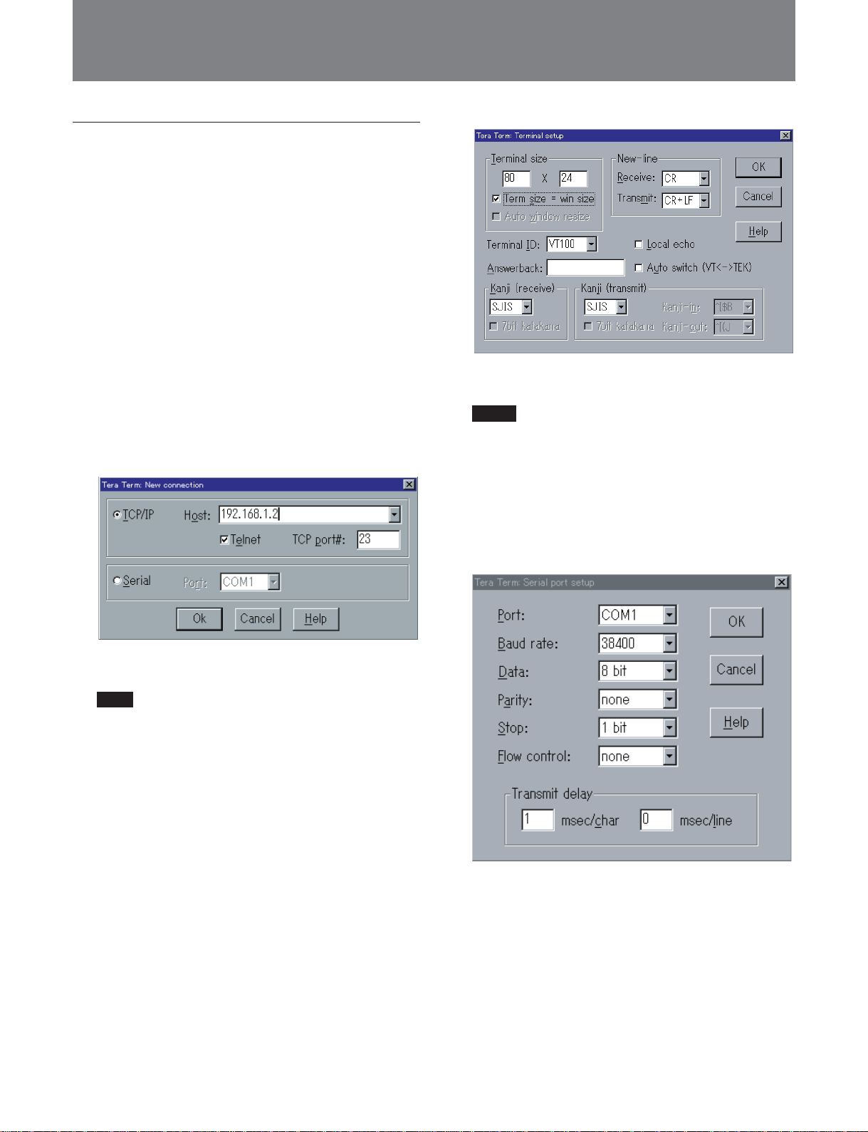
3 Start the terminal software (Tera Term in this
example).
Open the “New connection” dialog box.
4 Check the TCP/IP radio button.
Note
When using the RS-232C connector on this unit
connected to a serial port on the computer, check
the Serial radio button.
7 Confirm the settings, then click the OK button.
Notes
•Increasing the terminal size may cause a
malfunction.
•When using this unit with its RS-232C connector
connected to a computer serial port, set
“Transmit” to “CR.” Next, in the setup menu
select “Serial port setup,” and check the settings
in the dialog box (see figure below), then click
the OK button.
5 In the Host box, enter the IP address of this unit,
and then click the OK button.
The default setting of the IP address is
“192.168.1.2”.
For details of how to set the IP address, see “To change
the IP address” (page 14).
6 In the setup menu, select “Terminal setup.”
A dialog box appears.
26
Page 27
Changing Settings Using Telnet or RS-232C Terminals
Displaying the menu item categories and
menu items
Use the following procedure.
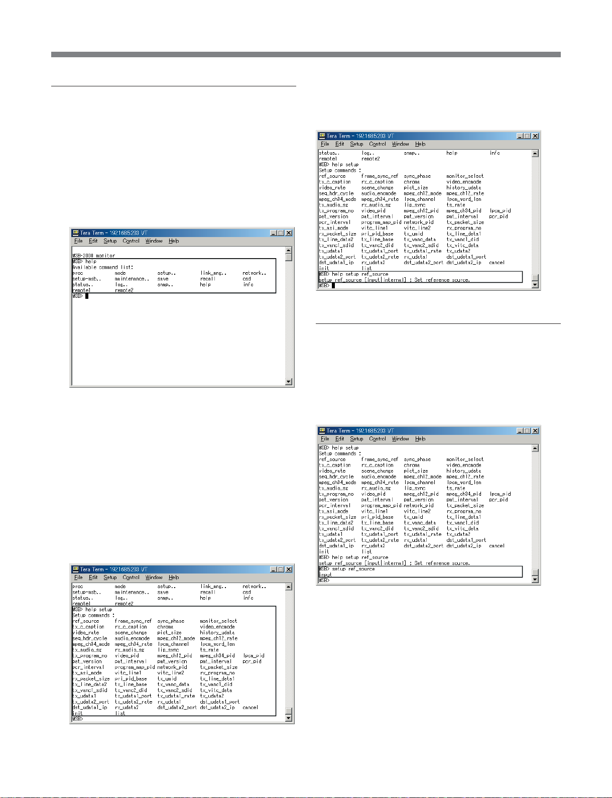
1 On the monitor screen, enter “help” after the
prompt.
A list of menu categories appears after the legend
“Available command list:”
If the category name is followed by two dots (“..”),
this indicates that there is more than one menu
item.
Displaying the available settings
Enter “help”, the category name, and the item name in
sequence after the prompt.
Checking the current settings of this unit
Enter the category name and item name in sequence
after the prompt.
The current settings appear.
The following figure shows “setup” specified as the
category name and “ref_source” as the item name.
2 To display the menu items, enter “help” after the
prompt, and then enter the category name.
The list of menu items appears after the legend
“Setup commands.”
(The following figure shows an example display
with “setup” specified as category name when txrx is selected in the “B: mode” menu.)
For more details of the menus, see the List of Menus
(page 36).
27
Page 28
Changing Settings Using Telnet or RS-232C Terminals
Changing the settings on this unit
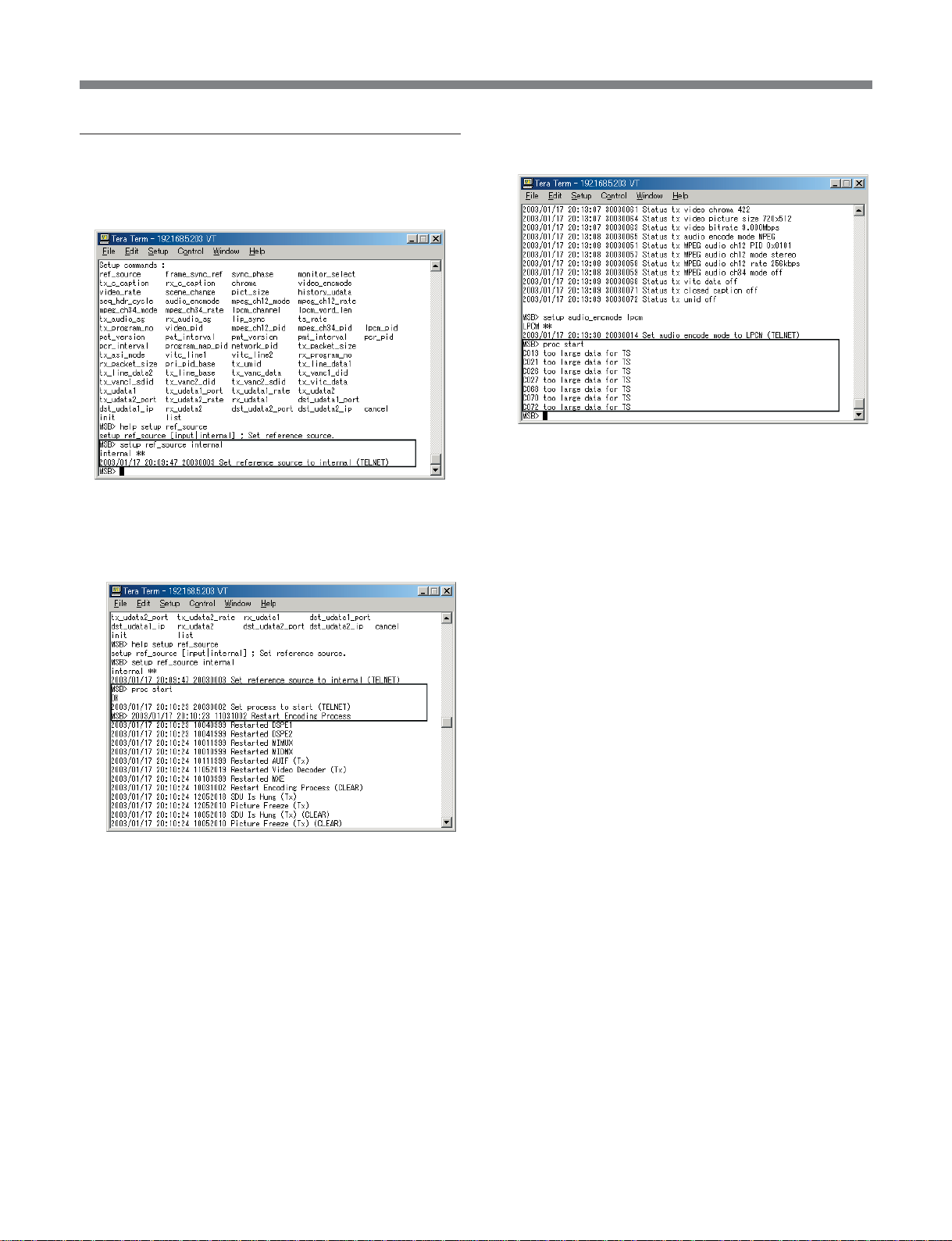
1 Enter the category name, item name, and new
setting in sequence after the prompt.
2 Enter “proc start” to enable the changed settings.
If there is no problem with the changed settings,
“OK” is returned, and this unit restarts.
If there is a problem with the changed settings, the
relevant menu item number is displayed.
28
Page 29
Changing Settings Using a Web Browser
Changing Settings Using a Web Browser
Preparations
When connecting the 10BASE-T connector of this unit
to an Ethernet connector of the host computer (PC)
with an Ethernet cable, carry out the following
operations.
For details of installation and connections for this unit,
refer to the supplied Installation Guide.
1 Power on this unit.
2 Power on the PC, and start Windows.
3 Start the Internet browser (Recommended:
Microsoft
make the necessary settings.
For the method of making the browser settings, see the
next section “Making the Internet browser settings.”
1)
Internet Explorer 5.0 or later), and
4 In the address box enter the IP address of this unit,
and press the Enter key.
Making the Internet browser settings
<For Microsoft Internet Explorer>
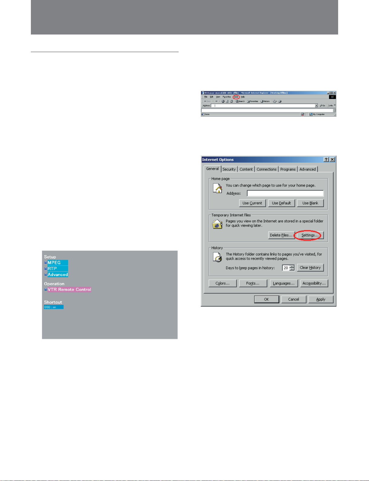
1 In the “Tools” menu, select “Internet Options.”
The “Internet Options” dialog box appears.
2 In the “General” tab, “Temporary Internet files”
section, click the “Settings” button.
The MSB-2000 GUI appears.
The default value for the IP address is
“192.168.1.2.”
For details of how to set the IP address, see “To change
the IP address” (page 14).
The “Settings” dialog box appears.
.........................................................................................................................................................................................................
1) Microsoft is a registered trademark of Microsoft
Corporation in the USA and other countries.
29
Page 30
Changing Settings Using a Web Browser
3 Under “Check for newer versions of stored pages”
select “Every visit to the page.”
<For Netscape Navigator1)>
Notes
•Please use Netscape Navigator version 4.7 or later.
•When using Netscape Navigator, while the MSB-
2000 GUI is displayed, source files may appear, or
the download window. In this case it is necessary to
run regedit.exe, to change the registry settings for a
cgi file. Doing this, however, may affect the
operation of other applications.
2 In the tree display, select “Advanced,” and check
“Enable JavaScript.”
3 In the tree display, select the “Cache” subnode of
“Advanced,” and under “Document in cache is
compared to document on network” select “Every
time.”
1 In the “Edit” menu, select “Preferences.”
The “Preferences” dialog box appears.
.........................................................................................................................................................................................................
1) Netscape Navigator is a registered trademark of
Netscape Communications Corporation in the U.S. and
other countries.
30
Page 31
Changing Settings Using a Web Browser
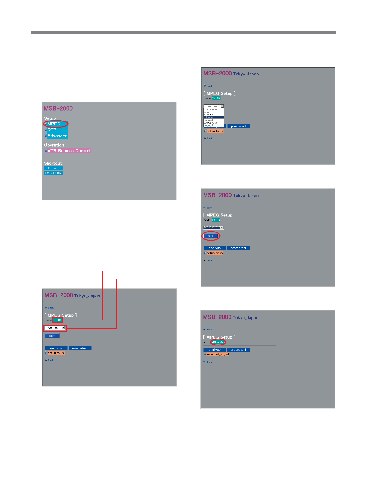
Changing the operation mode
To change the operation mode from the GUI, use the
following procedure.
1 In the GUI, click “MPEG” under “Setup.”
The MPEG Setup screen appears.
2 In the MPEG Setup screen, click the operation
mode display (indicating the current operation
mode).
3 Select the desired operation mode (for example
“sdi_to_asi”) from the list box.
4 Click the SET button.
The list box for operation mode selection appears.
Operation mode display
Opration mode list box
(Example display with “tx-rx” selected)
The unit’s operation mode changes and the new
operation mode is displayed.
31
Page 32
Changing Settings Using a Web Browser
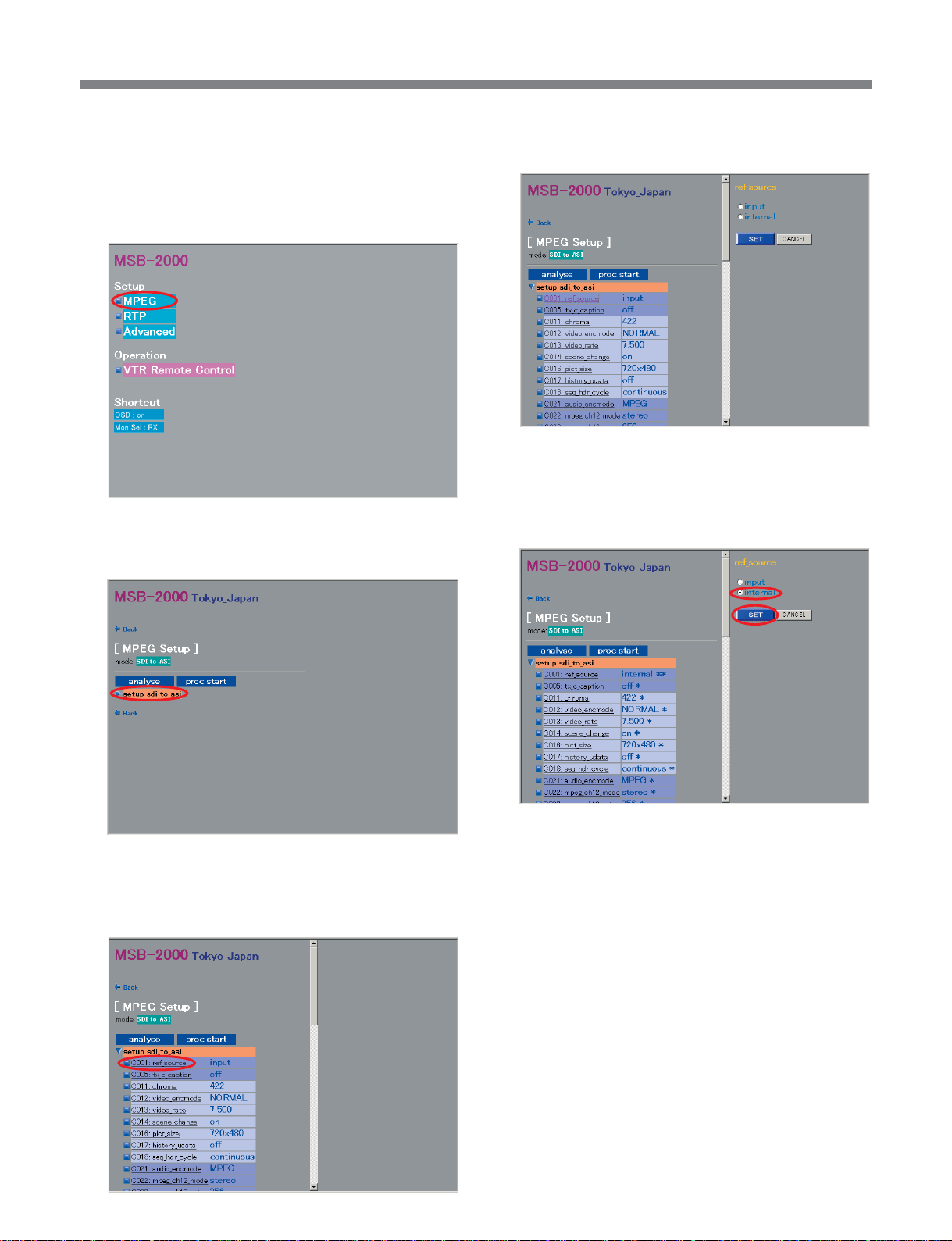
Changing Setup
Use the following procedure.
1 In the GUI, click “MPEG” under “Setup.”.
The MPEG Setup screen appears.
2 In the MPEG Setup screen, click “setup.”
A setting selection/input window appears at the
right of the screen.
4 Enter the setting value, or turn on the radio button
for the value you want to select, then click the SET
button.
This changes the setting, and “**” appears.
Submenu items of “setup” appear.
3 Click on the submenu item to be set (for example
“C001:ref_source”).
If the setting value is out of range
An error message appears in the setting indication
space. Reenter the setting.
For details of error messages, see page 86.
To cancel the setting change
Click the CANCEL button.
To select “auto” in “C013:video_rate” and
“C061:ts_rate”
In the field to enter the setting value, enter “auto.”
32
Page 33
Changing Settings Using a Web Browser
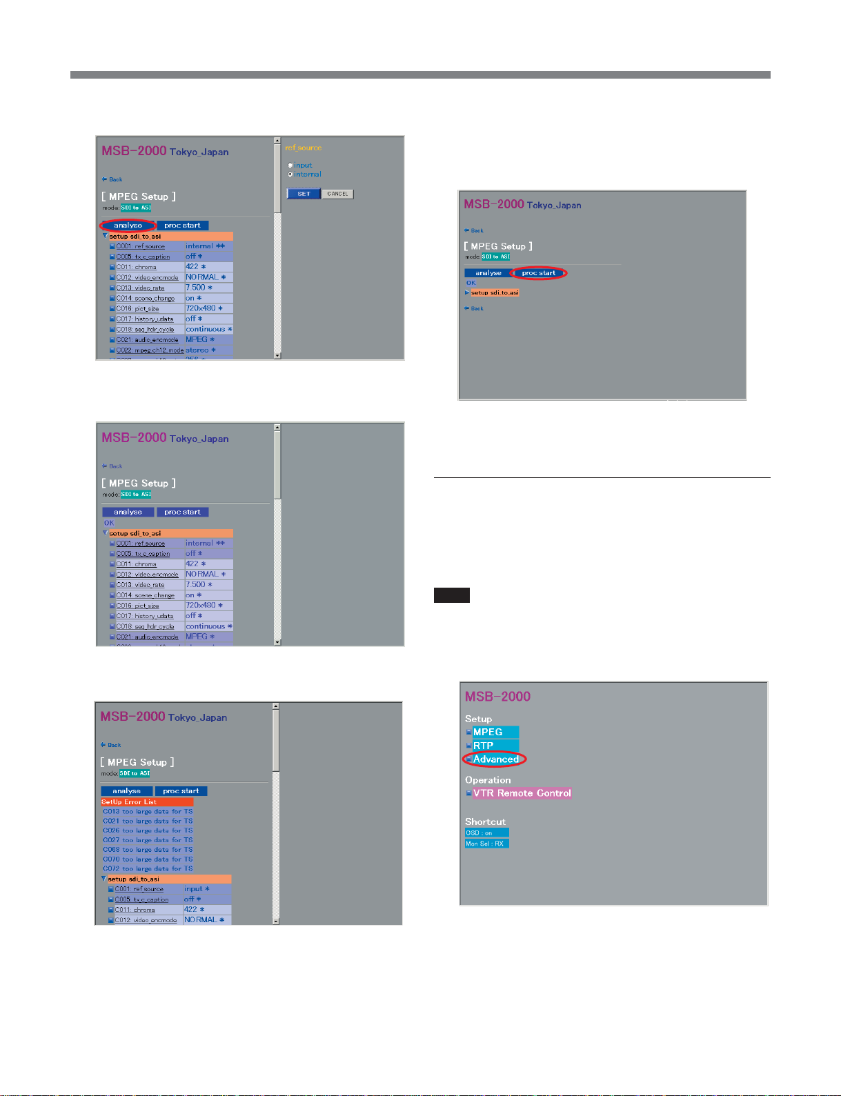
5 To check the settings, press the analyse button.
If there is no problem with the settings, “OK”
appears below the analyse button.
6 To confirm the settings, press the proc start button.
If there is no problem with the settings, “OK”
appears and the unit restarts.
For more details of the menus, see the List of Menus
(page 36).
Remote control of a VTR
If there is a problem with the settings, below the
analyze button, “SetUp Error List” is displayed.
For remote control of a VTR connected to the
REMOTE1 connector or REMOTE2 connector of this
unit from the GUI, use the following procedure.
Note
Set the VTR to enable remote control through a 9-pin
remote control cable.
1 In the GUI, click “Advanced” under “Setup.”
The Advanced Setup screen appears.
33
Page 34
Changing Settings Using a Web Browser
2 Perform the operations 1) to 3) below to enable
control of VTR.
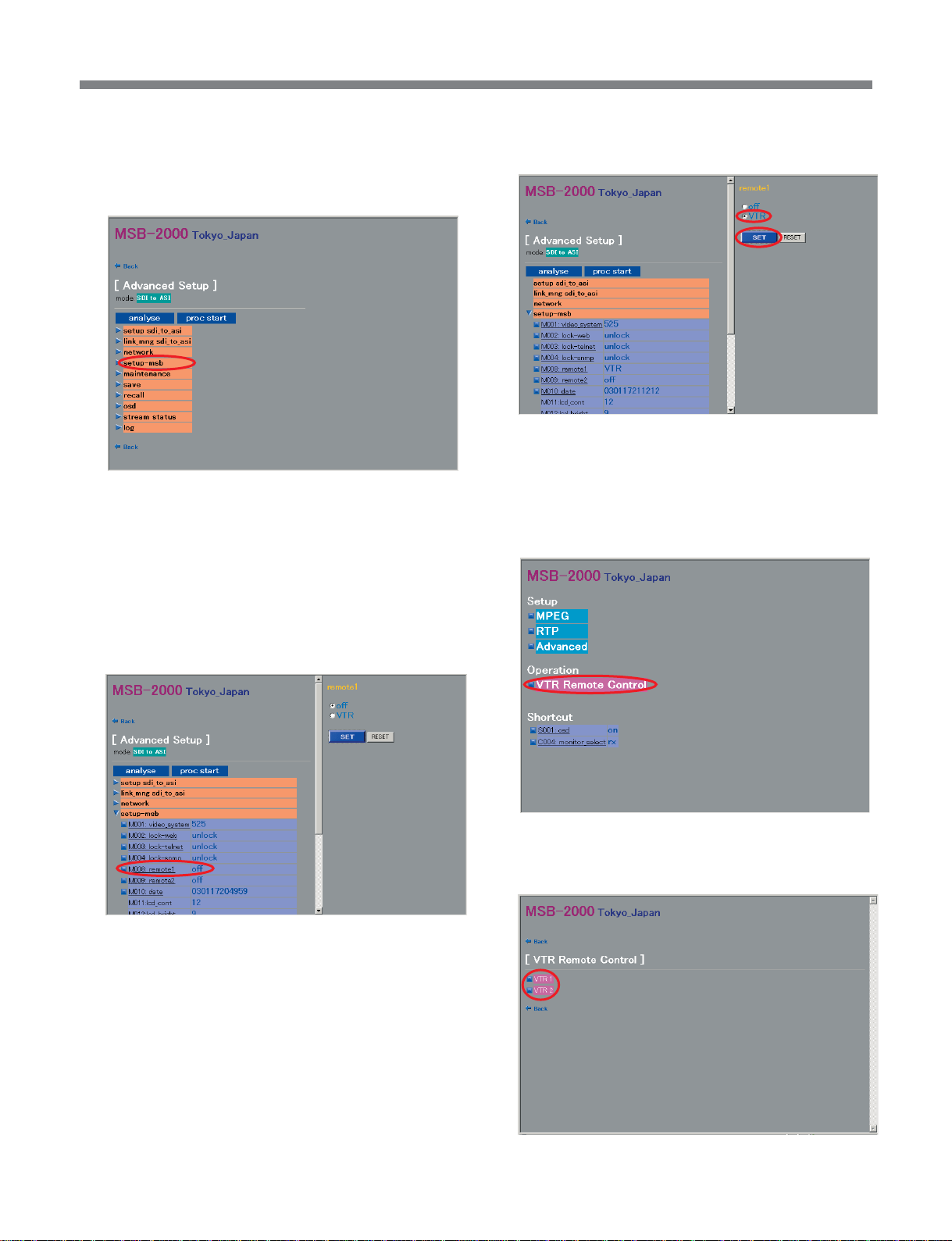
1) Click “setup-msb.”
Menu items of “setup-msb” appear.
2) Click the menu item “M008:remote1” or
“M009:remote2”. (The description hereafter
assumes that “M008:remote1” has been
selected.)
3) Turn on the VTR radio button, and click the
SET button.
This enables the VTR connected to the
REMOTE1 connector to be controlled from this
unit.
3 In the GUI, click “VTR Remote Control” under
“Operation.”
A setting selection window appears at the right
of the screen.
The VTR selection screen appears.
4 Click “VTR 1” or “VTR 2.”
The VTR control window appears.
34
Page 35
Changing Settings Using a Web Browser
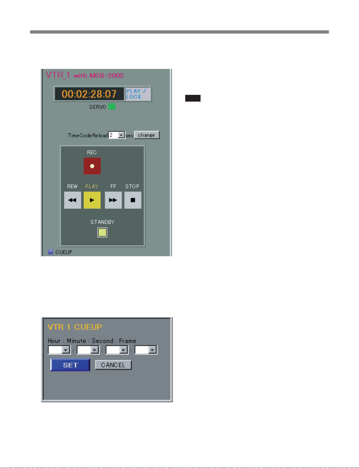
5 Select the timecode reload time from the list box,
and click the change button.
8 Enter the timecode, and click the SET button.
This cues up the VTR to the specified timecode
position.
Note
When remotely controlling the VTR, remember to take
into account any network delay.
6 Click the REC, REW, PLAY, FF, and STOP
buttons to control the VTR.
7 To cue up the VTR to a desired position, click the
CUEUP button.
The Cueup dialog box appears.
35
Page 36

List of Menus
List of Menus
The menu items are in the following categories.
A:proc (process)
B:mode
C: setup (tx-rx, tx-rx (cm), sdi_to_asi, asi_to_sdi,
sdti-cp_to_asi, asi_to_sdti-cp)
E:link_mng
L:network
M:setup-msb
N:maintenance
P:save
R:recall
S:osd
T:status
U:log
In the following tables, the factory default settings are
enclosed in boxes.
The following symbols are also used.
*: Not supported by Versions 1.01 to 1.30.
**: Available when the MSBA-20IP is installed.
Menu items not included in the categories
listed at left
help (RS232C/telnet)
info (RS232C/telnet)
remote1 “stop” “play” “rec” “ff” “rew” “cueup
{hhmmssff}”
“standby_on” “standby_off”
“status” “tc”
remote2 “stop” “play” “rec” “ff” “rew” “cueup
{hhmmssff}”
“standby_on” “standby_off”
“status” “tc”
snmp*** “init” “sys” “host” “comm” “trap”
For details of the snmp menu, see the section “SNMP
Commands” (page 90).
A:proc (process) menu
This is used as a setting value execution command.
Item number Category Item Function
A proc start Checks the consistency of setting values, and if there is no problem
carries out the setting change.
If there is an inconsistency, returns the command number of the
related setting.
analyse Checks the consistency of setting values, and if there is no problem
returns OK.
If there is an inconsistency, returns the command number of the
related setting.
B:mode menu
This is used as a operating mode selection command.
Item number Category Item Function
B mode tx-rx Bidirectional encoder/decoder mode (sdi_to_asi/asi_to_sdi)
tx-rx (cm) Bidirectional endoder/decoder mode, communication mode
sdi_to_asi SDI input encoder mode
asi_to_sdi SDI output decoder mode
sdti-cp_to_asi SDTI-CP input encoder mode
asi_to_sdti-cp SDTI-CP output decoder mode
36
Page 37
List of Menus
C:setup menu
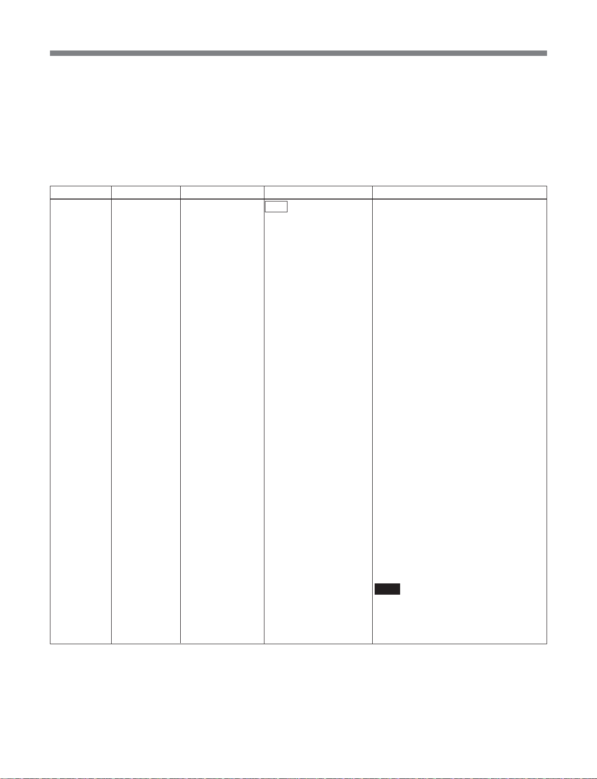
In this menu, you set setting values that depend on the
operating mode. Depending on the operating mode set
in the “B:mode” menu, the setting items corresponding
to the mode are selected. If the arguments are omitted,
the current setting is given as the return value.
•In tx-rx mode
Item number Category Item Arguments Function
C001 setup (Tx) ref_source input The SDI input is used as reference for the
system clock.
The internal frame phase is determined by
following the frame phase of the input.
When the SDI is switched with a router
switch or similar, if the phase difference of
the input video is within ±10 µs, the
decoded video is switched without
transients appearing. If within the Window
(±1.5H), then there are no transients on the
ASI TS stream. If the Window is exceeded,
in order to follow the input, and reestablish
the frame phase lock, the TS stream is
interrupted for a few seconds.
Use this on condition that the input signal
is stable, in order to use a fixed latency.
internal The SDI input is used as reference for the
system clock.
The internal frame phase is determined
from the phase of the first video frame
input. At the time of SDI input switching,
therefore, with the relative phase of the
input frame and internal frame, the latency
fluctuates within a range of one frame.
Depending on the latency fluctuation, an
offset is applied to the audio PTS, and lip
sync is adjusted. Therefore, depending on
the phase difference between input frame
and internal frame, the audio stream may
be interrupted for several seconds.
With the switching timing, image
degradation occurs up to a maximum of
one frame, but transients do not appear on
the ASI TS stream.
Use this when using asynchronous SDI
switched with a router switch or similar, in
order to output a stable TS stream even if
there is degradation in the input signal.
Note
If the switching timing of the input signal is
outside the standard (SMPTE RP168),
there may be degradation of the TS stream
or image.
37
Page 38
List of Menus
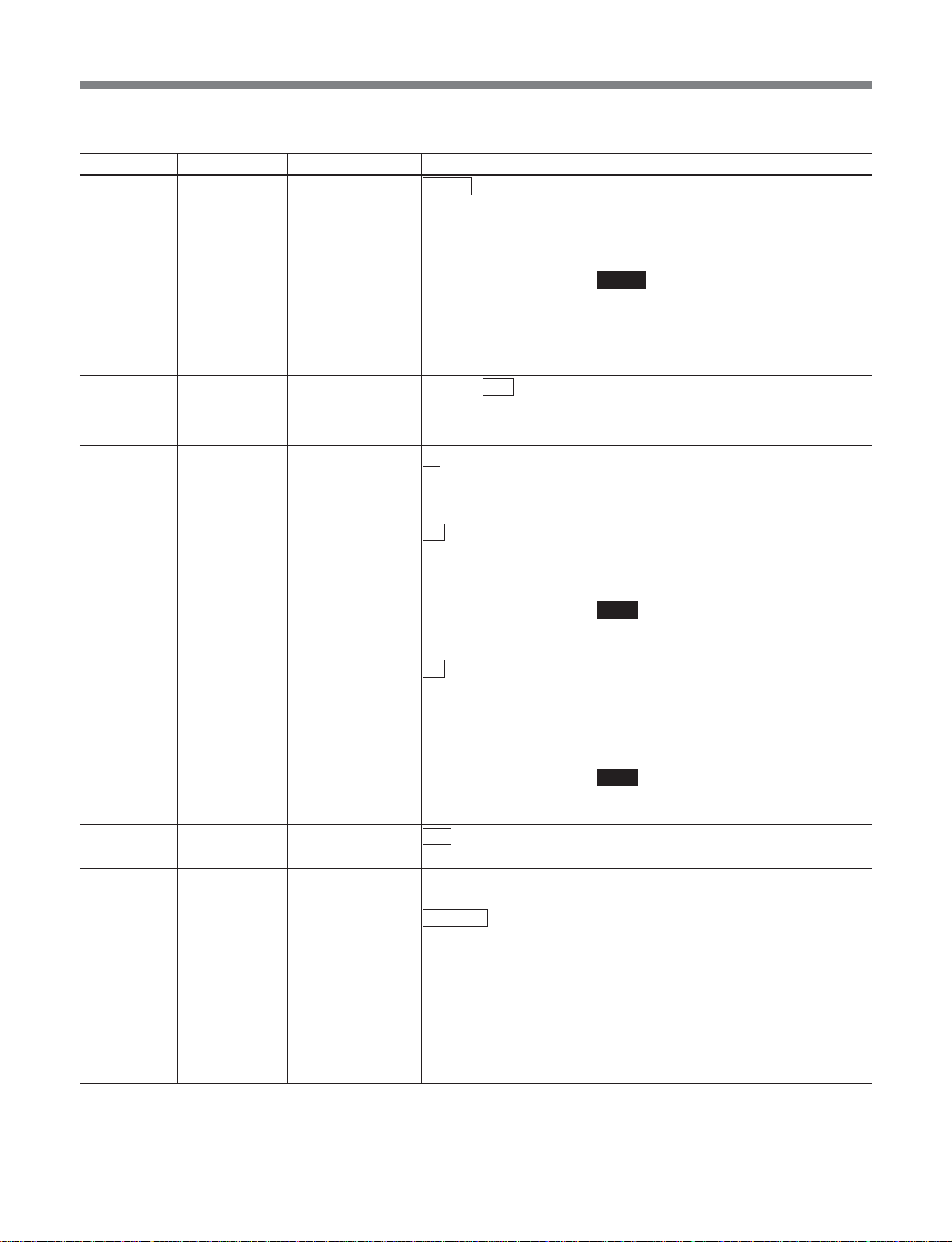
(In tx-rx mode)
Item number Category Item Arguments Function
C002 setup (Rx) frame_sync_ref stream The STC obtained from the input stream is
used as the reference for SDI output.
ref_in The external analog composite input to the
REF IN connector is used as the reference
for SDI output.
Notes
• The analog reference must be a signal
such as black burst, with no amplitude
fluctuation.
• When ref_in is selected, the wordlength
for linear PCM audio samples is 16 bits.
C003 setup (Rx) sync_phase 0x600 to 800 to 9ff Specifies any hexadecimal value from
0x600 to 0x9ff, to enable fine adjustment of
the SDI output sync phase.
The adjustment range is ±18.9 µs.
C004 setup monitor_select rx Selects the decoder monitor for the monitor
tx Selects the encoder monitor for the monitor
C005 setup (Tx) tx_c_caption off Disables processing to transmit closed
on Enables processing to transmit closed
C006 setup (Rx) rx_c_caption off Disables processing to put closed captions
on Enables processing to put closed captions
C011 setup (Tx) chroma 422 This is 422P@ML.
420 This is MP@ML.
C012 setup (Tx) video_encmode IMX This IMX encoding mode is characterized
NORMAL This encoding mode is M=3 with Long
LD This is a low delay mode, with All P Intra
NORMAL_BL This encoding mode is M=3 with Long
output.
output.
captions as Picture user data.
captions as Picture user data.
Note
This item is effective only when
video_system is 525.
transmitted as Picture user data on base
band.
transmitted as Picture user data on base
band.
Note
This item is effective only when
video_system is 525.
by All Intra CBG.
GOP CBR.
This yields a fixed latency, regardless of
the set bit rate.
slice.
GOP CBR.
This yields the minimum latency,
depending on the set bit rate.
38
Page 39
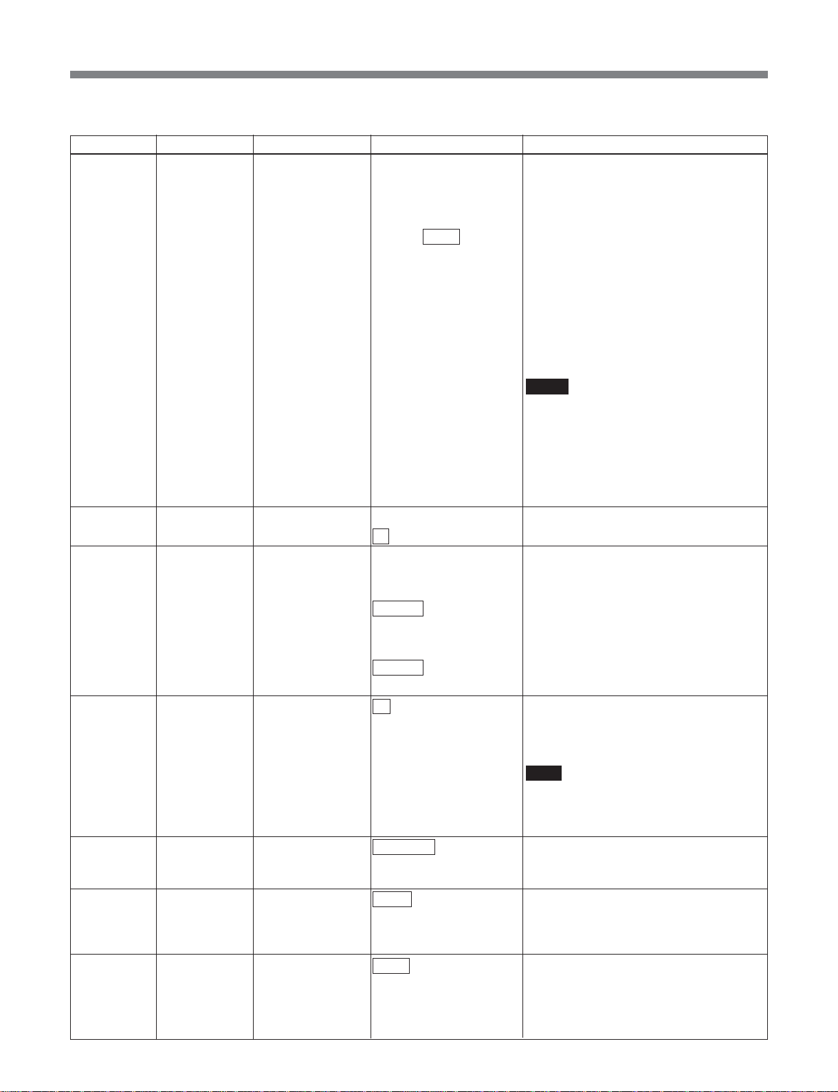
List of Menus
(In tx-rx mode)
Item number Category Item Arguments Function
C013 setup (Tx) video_rate auto The video ES bit rate is calculated
manual The video ES bit rate can be specified in
4.000 to 7.500 to 50.000 units of 2 kbps. If a certain degree of error
C014 setup (Tx) scene_change off Disables scene change processing.
on Enables scene change processing.
C016 setup (Tx) pict_size Sets the picture size when encoding is
720x480 Sets the picture size to 720x480.
720x512 Sets the picture size to 720x512.
720x576 Sets the picture size to 720x576.
720x608 Sets the picture size to 720x608.
C017* setup (Tx) history_udata off History data for parameter referring re-
on History data for parameter referring re-
C018 setup (Tx) seq_hdr_cycle continuous Puts the sequence header on every
interstitial Puts the sequence header interstitially.
C021 setup (Tx) audio_encmode MPEG Specifies the audio encoding as MPEG1
LPCM Specifies the audio encoding as linear
C022 setup (Tx) mpeg_ch12_mode stereo Specifies the audio mode for channels 1
dual Specifies the audio mode for channels 1
off Disables the audio for channels 1 and 2.
automatically from the TS rate and audio
settings. An 'A' appears after the numeric
value.
occurs, this is controlled to be below the
setting value.
Argument unit Mbps
When video_enc mode is IMX:
30.000, 35.000, 40.000, 45.000, 50.000
Mbps
When chroma mode is 420:
4.000 to 15.000 Mbps
In other cases:
6.000 to 30.000 Mbps
Notes
• When the MSBA-20IP is installed, keep
ts_rate within 35.000 Mbps.
• If “N014:maintenance video_rate” is set to
“extended,” and video_encmode is other
than IMX, the minimum limit for
video_rate is 2 Mbps. Note, however, that
operation cannot be guaranteed at
present.
performed.
• When video_system is 525:
• When video_system is 625:
encoding is not included in the stream.
encoding is included in the stream.
Note
• This is supported as an option.
• This item is effective only when
video_encmode is normal.
picture.
layerII.
PCM (SMPTE 302M).
and 2 as stereo.
and 2 as dual.
39
Page 40
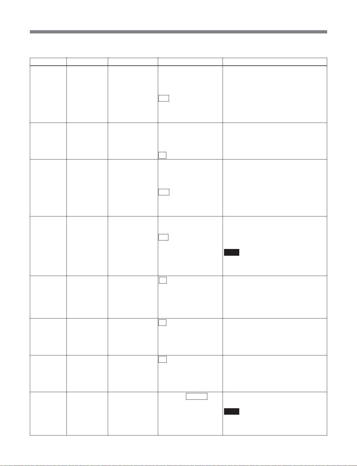
List of Menus
(In tx-rx mode)
Item number Category Item Arguments Function
C023 setup (Tx) mpeg_ch12_rate 128 Sets the bit rate of the audio for channels 1
192 Sets the bit rate of the audio for channels 1
256 Sets the bit rate of the audio for channels 1
384 Sets the bit rate of the audio for channels 1
C024 setup (Tx) mpeg_ch34_mode stereo Specifies the audio mode for channels 3
dual Specifies the audio mode for channels 3
off Disables the audio for channels 3 and 4.
C025 setup (Tx) mpeg_ch34_rate 128 Sets the bit rate of the audio for channels 3
192 Sets the bit rate of the audio for channels 3
256 Sets the bit rate of the audio for channels 3
384 Sets the bit rate of the audio for channels 3
C026 setup (Tx) lpcm_channel 1-2 Specifies channels 1 and 2 for linear PCM.
3-4 Specifies channels 3 and 4 for linear PCM.
1-4 Specifies channels 1, 2, 3, and 4 for linear
C027 setup (Tx) lpcm_word_len 16 Sets the linear PCM sample word length to
20 Sets the linear PCM sample word length to
24 Sets the linear PCM sample word length to
C028 setup (Tx) tx_audio_sg off Disables the internal test signal generator.
1 kHz Enables the internal test signal generator
silence Enables the internal test signal generator
C051 setup (Rx) rx_audio_sg off Disables the internal test signal generator.
1 kHz Enables the internal test signal generator
silence Enables the internal test signal generator
C052 setup (Rx) lip_sync –20.000 to +00.000 Carries out lip sync fine adjustment.
to +20.000 Unit: ms
and 2 to 128 kbps.
and 2 to 192 kbps.
and 2 to 256 kbps.
and 2 to 384 kbps.
and 4 as stereo.
and 4 as dual.
and 4 to 128 kbps.
and 4 to 192 kbps.
and 4 to 256 kbps.
and 4 to 384 kbps.
PCM.
Note
If “tx-rx” is selected in the B:mode menu,
note that only 4 channels at the maximum
of Linear PCM Audio are supported.
16 bits.
20 bits.
24 bits.
to output a 1 kHz sine wave.
to output silence.
to output a 1 kHz sine wave.
to output silence.
Note
When set to a negative value, note that
operation may not be guaranteed,
depending on the system status.
40
Page 41
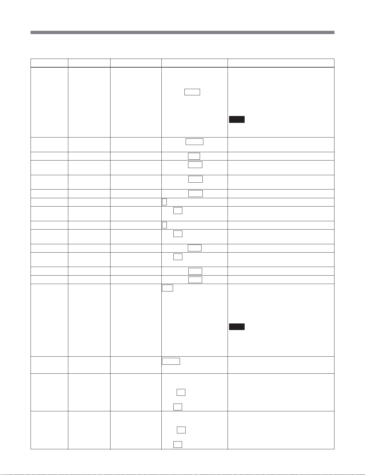
List of Menus
(In tx-rx mode)
Item number Category Item Arguments Function
C061 setup (Tx) ts_rate auto The TS rate is calculated automatically. An
manual The TS rate can be specified in units of
3.000 to 8.448 to 68.000 1 kbps. If a certain degree of error occurs,
C062 setup (Tx) tx_program_no 00001 to 00200 to 65535 Specifies the program number declared in
C063 setup (Tx) video_pid 0x0010 to 00ff to 1ffe Specifies the video PID.
C064 setup (Tx) mpeg_ch12_pid 0x0010 to 0101 to 1ffe Specifies the PID for MPEG audio
C065 setup (Tx) mpeg_ch34_pid 0x0010 to 0102 to 1ffe Specifies the PID for MPEG audio
C066 setup (Tx) lpcm_pid 0x0010 to 0100 to 1ffe Specifies the PID for linear PCM audio.
C067 setup (Tx) pat_version 0 to 31 Specifies the PAT version number.
C068 setup (Tx) pat_interval 1 to 33 to 100 Sets the PAT generation interval.
C069 setup (Tx) pmt_version 0 to 31 Specifies the PMT version number.
C070 setup (Tx) pmt_interval 1 to 33 to 100 Sets the PMT generation interval.
C071 setup (Tx) pcr_pid 0x0010 to 00fe to 1ffe Specifies the PID for PCR.
C072 setup (Tx) pcr_interval 1 to 33 to 100 Sets the PCR generation interval.
C073 setup (Tx) program_map_pid 0x0010 to 00c8 to 1ffe Specifies the PID for PMT.
C074* setup (Tx) network_pid 0x0010 to 0064 to 1ffe Specifies the PID for NIT.
C075 setup (Tx) tx_packet_size 188 Specifies the output TS packet size as 188
204 Specifies the output TS packet size as 204
C076 setup (Tx) tx_asi_mode packet Outputs output TS in packet mode.
burst Outputs output TS in burst mode.
C091 setup (Rx) vitc_line1 off Disables processing to put VITC
10 to 18 to 20 (525) Specifies line number to hold VITC
7 to 21 to 22 (625)
C092 setup (Rx) vitc_line2 off Disables processing to put VITC
10 to 18 to 20 (525) Specifies line number to hold VITC
7 to 21 to 22 (625)
‘A’ appears after the numeric value.
this is controlled to be below the setting
value.
Argument unit: Mbps
Note
When the MSBA-20IP is installed, keep
ts_rate within 35.000 Mbps.
PAT.
channels 1 and 2.
channels 3 and 4.
Unit: 1 ms
Unit: 1 ms
Unit: ms
bytes.
bytes.
(16 bytes of dummy data inlucluded.)
Note
When an MSBA-20IP board is installed,
the TS packet size for an MPEG stream
output through RTP is fixed at 188 bytes,
irrespective of this setting.
transmitted as private data on base band.
transmitted as private data.
transmitted as private data on base band.
transmitted as private data.
41
Page 42
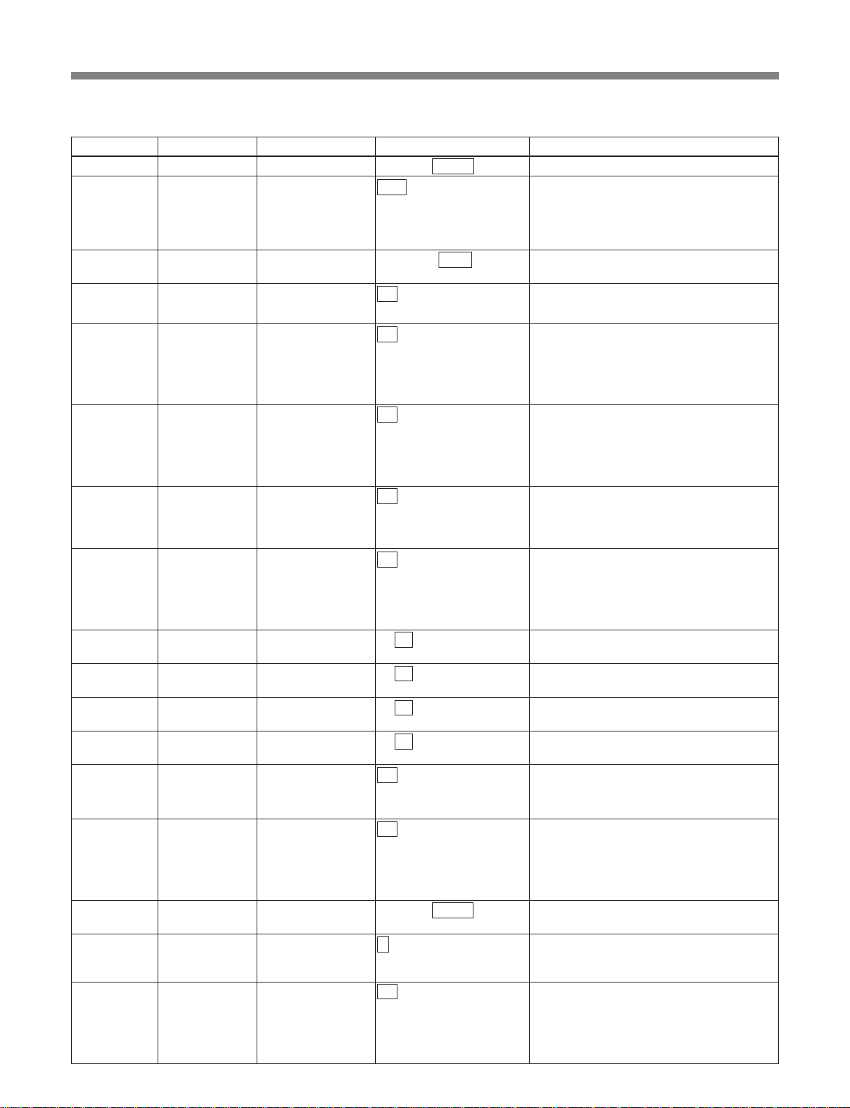
List of Menus
(In tx-rx mode)
Item number Category Item Arguments Function
C101 setup (Rx) rx_program_no 00001 to 00200 to 65535 Specifies program number for decoding.
C102 setup (Rx) rx_packet_size auto Automatically recognizes input TS packet
size.
188
204
C111 setup (Tx) pri_pid_base 0x0010 to 00c0 to 1ff7 Specifies the base PID for transferring
C112* setup (Tx) tx_umid off Disables UMID.
on Enables UMID. PID is “pri_pid_base” +0.
C113 setup (Tx) tx_line_data1 off Disables uncompressed line data
on Enables uncompressed line data
C114 setup (Tx) tx_line_data2 off Disables uncompressed line data
on Enables uncompressed line data
C115 setup (Tx) tx_line_base 12 to 21 Specifies the line number of the
C116* setup (Tx) tx_vanc_data off Disables ancillary data processing in the
on Enables ancillary data processing in the
C117* setup (Tx) tx_vanc1_did 0x 00 to ff Specifies the DID for vertical blanking
C118* setup (Tx) tx_vanc1_sdid 0x 00 to ff Specifies the SDID for vertical blanking
C119* setup (Tx) tx_vanc2_did 0x 00 to ff Specifies the DID for vertical blanking
C120* setup (Tx) tx_vanc2_sdid 0x 00 to ff Specifies the SDID for vertical blanking
C121 setup (Tx) tx_vitc_data off Disables VITC private data transfer.
on Enables VITC private data transfer.
C124* setup (Tx) tx_udata1 off Disables getting user data1 from the UDP
on Enables getting user data1 from the UDP
C125* setup (Tx) tx_udata1_port 05000 to 09000 to 65535 Sets the UDP port No. for picking up user
C126* setup (Tx) tx_udata1_rate 1 to 30 Specifies rate for getting user data1 from
C127* setup (Tx) tx_udata2 off Disables getting user data 2 from the UDP
on Enables getting user data 2 from the UDP
Sets input TS packet size to fixed 188 bytes.
Sets input TS packet size to fixed 204 bytes.
private data.
processing of 1st line.
processing of 1st line.
PID is “pri_pid_base” +1.
processing of 2nd line.
processing of 2nd line.
PID is “pri_pid_base” +1.
uncompressed line. This line and the
following line can be transferred as
uncompressed lines.
vertical blanking interval.
vertical blanking interval. PID is
“pri_pid_base” +2.
interval ancillary data.
interval ancillary data.
interval ancillary data.
interval ancillary data.
PID is “pri_pid_base” +3.
port, via the MSBA-20IP.
port, via the MSBA-20IP.
PID is “pri_pid_base” +6.
data1 from the MSBA-20IP.
the MSBA-20IP.
Unit: Mbps
port, via the MSBA-20IP.
port, via the MSBA-20IP.
PID is “pri_pid_base” +7.
42
Page 43
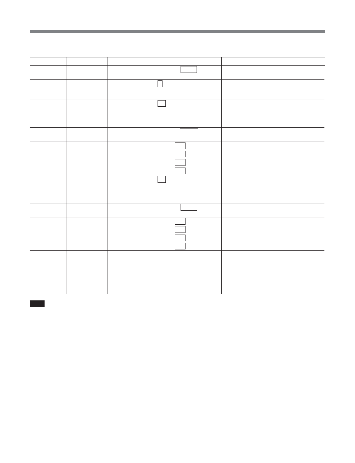
List of Menus
(In tx-rx mode)
Item number Category Item Arguments Function
C128* setup (Tx) tx_udata2_port 05000 to 09001 to 65535 Sets the UDP port No. for picking up user
data 2 from the MSBA-20IP.
C129* setup (Tx) tx_udata2_rate 1 to 30 Specifies rate for getting user data 2 from
the MSBA-20IP.
Unit: Mbps
C141* setup (Rx) rx_udata1 off Disables user data1 output from the UDP
port, via the MSBA-20IP.
on Enables user data1 output from the UDP
port, via the MSBA-20IP.
C142* setup (Rx) dst_udata1_port 05000 to 09000 to 65535 Sets the UDP port No. for outputting user
data1 from the MSBA-20IP.
C143* setup(Rx) dst_udata1_ip 000 to 192 to 255. Sets the destination IP address for output
000 to 168 to 255.
000 to 001 to 255.
000 to 003 to 255
C144* setup (Rx) rx_udata2 off Disables user data 2 output from the UDP
on Enables user data 2 output from the UDP
C145* setup (Rx) dst_udata2_port 05000 to 09001 to 65535 Sets the UDP port No. for outputting user
C146* setup (Rx) dst_udata2_ip 000 to 192 to 255. Sets the destination IP address for output
000 to 168 to 255.
000 to 001 to 255.
000 to 003 to 255
C998 setup cancel – Cancels a setup change before execution.
C999 setup init – Returns setup items to their factory default
– setup list – Displays the list set in setup.
of user data1 from the MSBA-20IP.
port, via the MSBA-20IP.
port, via the MSBA-20IP.
data 2 from the MSBA-20IP.
of user data 2 from the MSBA-20IP
settings.
This is a special-purpose command for
RS232C/telnet operation.
.
Note
“C124” to “C146” are commands for I/O of UDP
port user data as DVB-ASI (option functions), but
are not currently supported.
43
Page 44
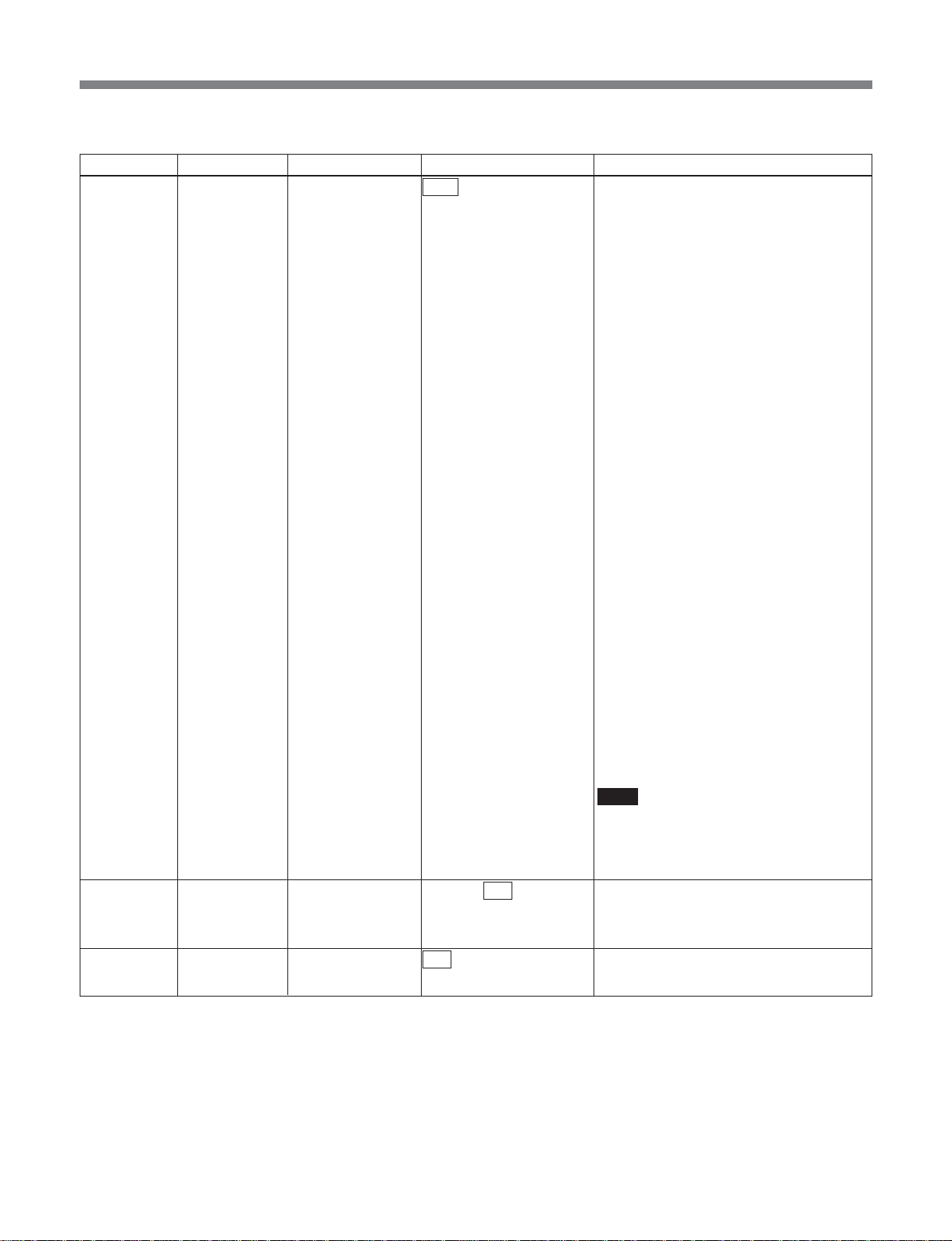
List of Menus
•In tx-rx (cm) mode
Item number Category Item Arguments Function
C001 setup (Tx) ref_source input The SDI input is used as reference for the
system clock.
The internal frame phase is determined by
following the frame phase of the input.
When the SDI is switched with a router
switch or similar, if the phase difference of
the input video is within ±10 µs, the
decoded video is switched without
transients appearing. If within the Window
(±1.5H), then there are no transients on the
ASI TS stream. If the Window is exceeded,
in order to follow the input, and reestablish
the frame phase lock, the TS stream is
interrupted for a few seconds.
Use this on condition that the input signal
is stable, in order to use a fixed latency.
internal The SDI input is used as reference for the
system clock.
The internal frame phase is determined
from the phase of the first video frame
input. At the time of SDI input switching,
therefore, with the relative phase of the
input frame and internal frame, the latency
fluctuates within a range of one frame.
Depending on the latency fluctuation, an
offset is applied to the audio PTS, and lip
sync is adjusted. Therefore, depending on
the phase difference between input frame
and internal frame, the audio stream may
be interrupted for several seconds.
With the switching timing, image
degradation occurs up to a maximum of
one frame, but transients do not appear on
the ASI TS stream.
Use this when using asynchronous SDI
switched with a router switch or similar, in
order to output a stable TS stream even if
there is degradation in the input signal.
Note
If the switching timing of the input signal is
outside the standard (SMPTE RP168),
there may be degradation of the TS stream
or image.
C003 setup (Rx) sync_phase 0x600 to 800 to 9ff Specifies any hexadecimal value from
C011 setup (Tx) chroma 422 This is 422P@ML.
420 This is MP@ML.
0x600 to 0x9ff, to enable fine adjustment of
the SDI output sync phase.
The adjustment range is ±18.9 µs.
44
Page 45
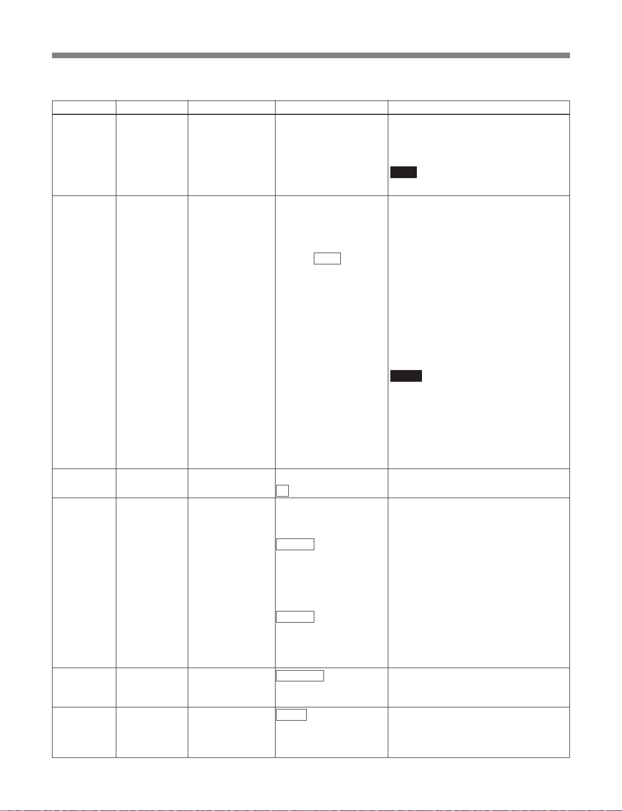
List of Menus
(In tx-rx (cm) mode)
Item number Category Item Arguments Function
C012 setup (Tx) video_encmode LD This is a low delay mode, with All P Intra
slice.
SLD* This is a low delay mode, using field
C013 setup (Tx) video_rate auto The video ES bit rate is calculated
manual The video ES bit rate can be specified in
4.000 to 7.500 to 50.000 units of 2 kbps. If a certain degree of error
C014 setup (Tx) scene_change off Disables scene change processing.
on Enables scene change processing.
C016 setup (Tx) pict_size Sets the picture size when encoding is
720x480 Sets the picture size to 720x480.
544x480 Sets the picture size to 544x480.
480x480 Sets the picture size to 480x480.
352x480 Sets the picture size to 352x480.
720x576 Sets the picture size to 720x576.
544x576 Sets the picture size to 544x576.
480x576 Sets the picture size to 480x576.
352x576 Sets the picture size to 352x576.
C018 setup (Tx) seq_hdr_cycle continuous Puts the sequence header on every
interstitial Puts the sequence header interstitially.
C021 setup (Tx) audio_encmode MPEG Specifies the audio encoding as MPEG1
LPCM Specifies the audio encoding as linear
structure.
Note
This is supported as an option.
automatically from the TS rate and audio
settings. An 'A' appears after the numeric
value.
occurs, this is controlled to be below the
setting value.
Argument unit Mbps
When video_enc mode is IMX:
30.000, 35.000, 40.000, 45.000, 50.000
Mbps
When chroma mode is 420:
4.000 to 15.000 Mbps
In other cases:
6.000 to 30.000 Mbps
Notes
• When the MSBA-20IP is installed, keep
ts_rate within 35.000 Mbps.
• If “N014:maintenance video_rate” is set to
“extended,” and video_encmode is other
than IMX, the minimum limit for
video_rate is 2 Mbps. Note, however, that
operation cannot be guaranteed at
present.
performed.
• When video_system is 525:
• When video_system is 625:
picture.
layerII.
PCM (SMPTE 302M).
45
Page 46

List of Menus
(In tx-rx (cm) mode)
Item number Category Item Arguments Function
C022 setup (Tx) mpeg_ch12_mode stereo Specifies the audio mode for channels 1
dual Specifies the audio mode for channels 1
off Disables the audio for channels 1 and 2.
C023 setup (Tx) mpeg_ch12_rate 128 Sets the bit rate of the audio for channels 1
192 Sets the bit rate of the audio for channels 1
256 Sets the bit rate of the audio for channels 1
384 Sets the bit rate of the audio for channels 1
C024 setup (Tx) mpeg_ch34_mode stereo Specifies the audio mode for channels 3
dual Specifies the audio mode for channels 3
off Disables the audio for channels 3 and 4.
C025 setup (Tx) mpeg_ch34_rate 128 Sets the bit rate of the audio for channels 3
192 Sets the bit rate of the audio for channels 3
256 Sets the bit rate of the audio for channels 3
384 Sets the bit rate of the audio for channels 3
C026 setup (Tx) lpcm_channel 1-2 Specifies channels 1 and 2 for linear PCM.
3-4 Specifies channels 3 and 4 for linear PCM.
1-4 Specifies channels 1, 2, 3, and 4 for linear
C027 setup (Tx) lpcm_word_len 16 Sets the linear PCM sample word length to
20 Sets the linear PCM sample word length to
24 Sets the linear PCM sample word length to
C028 setup (Tx) tx_audio_sg off Disables the internal test signal generator.
1 kHz Enables the internal test signal generator
silence Enables the internal test signal generator
C051 setup (Rx) rx_audio_sg off Disables the internal test signal generator.
1 kHz Enables the internal test signal generator
silence Enables the internal test signal generator
and 2 as stereo.
and 2 as dual.
and 2 to 128 kbps.
and 2 to 192 kbps.
and 2 to 256 kbps.
and 2 to 384 kbps.
and 4 as stereo.
and 4 as dual.
and 4 to 128 kbps.
and 4 to 192 kbps.
and 4 to 256 kbps.
and 4 to 384 kbps.
PCM.
Note
If “tx-rx” is selected in the B:mode menu,
note that only 4 channels at the maximum
of Linear PCM Audio are supported.
16 bits.
20 bits.
24 bits.
to output a 1 kHz sine wave.
to output silence.
to output a 1 kHz sine wave.
to output silence.
46
Page 47
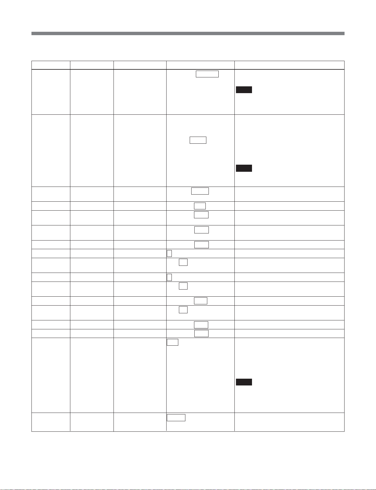
List of Menus
(In tx-rx (cm) mode)
Item number Category Item Arguments Function
C052 setup (Rx) lip_sync –20.000 to +00.000 Carries out lip sync fine adjustment.
C061 setup (Tx) ts_rate auto The TS rate is calculated automatically. An
C062 setup (Tx) tx_program_no 00001 to 00200 to 65535 Specifies the program number declared in
C063 setup (Tx) video_pid 0x0010 to 00ff to 1ffe Specifies the video PID.
C064 setup (Tx) mpeg_ch12_pid 0x0010 to 0101 to 1ffe Specifies the PID for MPEG audio
C065 setup (Tx) mpeg_ch34_pid 0x0010 to 0102 to 1ffe Specifies the PID for MPEG audio
C066 setup (Tx) lpcm_pid 0x0010 to 0100 to 1ffe Specifies the PID for linear PCM audio.
C067 setup (Tx) pat_version 0 to 31 Specifies the PAT version number.
C068 setup (Tx) pat_interval 1 to 33 to 100 Sets the PAT generation interval.
C069 setup (Tx) pmt_version 0 to 31 Specifies the PMT version number.
C070 setup (Tx) pmt_interval 1 to 33 to 100 Sets the PMT generation interval.
C071 setup (Tx) pcr_pid 0x0010 to 00fe to 1ffe Specifies the PID for PCR.
C072 setup (Tx) pcr_interval 1 to 33 to 100 Sets the PCR generation interval.
C073 setup (Tx) program_map_pid 0x0010 to 00c8 to 1ffe Specifies the PID for PMT.
C074* setup (Tx) network_pid 0x0010 to 0064 to 1ffe Specifies the PID for NIT.
C075 setup (Tx) tx_packet_size 188 Specifies the output TS packet size as 188
C076 setup (Tx) tx_asi_mode packet Outputs output TS in packet mode.
to +20.000 Unit: ms
Note
When set to a negative value, note that
operation may not be guaranteed,
depending on the system status.
‘A’ appears after the numeric value.
manual The TS rate can be specified in units of
3.000 to 8.448 to 68.000 1 kbps. If a certain degree of error occurs,
this is controlled to be below the setting
value.
Argument unit: Mbps
Note
When the MSBA-20IP is installed, keep
ts_rate within 35.000 Mbps.
PAT.
channels 1 and 2.
channels 3 and 4.
Unit: 1 ms
Unit: 1 ms
Unit: ms
bytes.
204 Specifies the output TS packet size as 204
bytes.
(16 bytes of dummy data inlucluded.)
Note
When an MSBA-20IP board is installed,
the TS packet size for an MPEG stream
output through RTP is fixed at 188 bytes,
irrespective of this setting.
burst Outputs output TS in burst mode.
47
Page 48
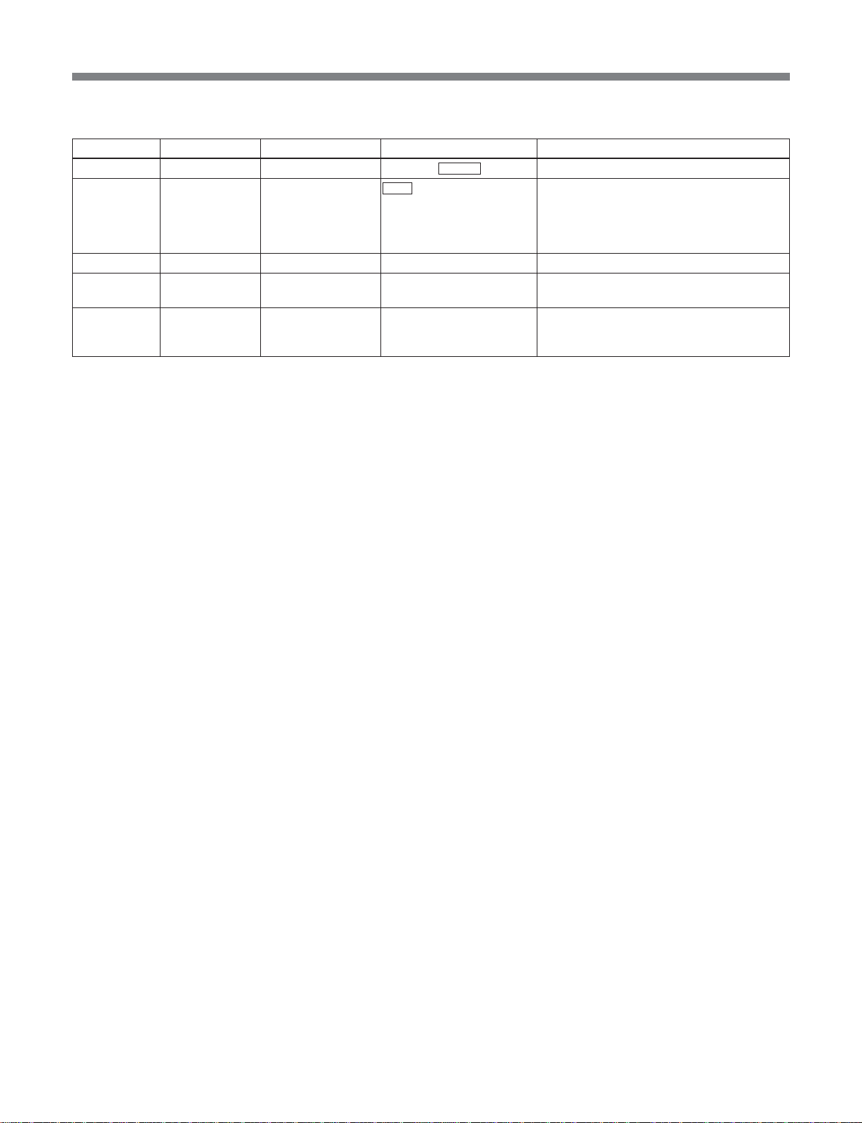
List of Menus
(In tx-rx (cm) mode)
Item number Category Item Arguments Function
C101 setup (Rx) rx_program_no 00001 to 00200 to 65535 Specifies program number for decoding.
C102 setup (Rx) rx_packet_size auto Automatically recognizes input TS packet
size.
188
204
C998 setup cancel – Cancels a setup change before execution.
C999 setup init – Returns setup items to their factory default
– setup list – Displays the list set in setup.
Sets input TS packet size to fixed 188 bytes.
Sets input TS packet size to fixed 204 bytes.
settings.
This is a special-purpose command for
RS232C/telnet operation.
48
Page 49
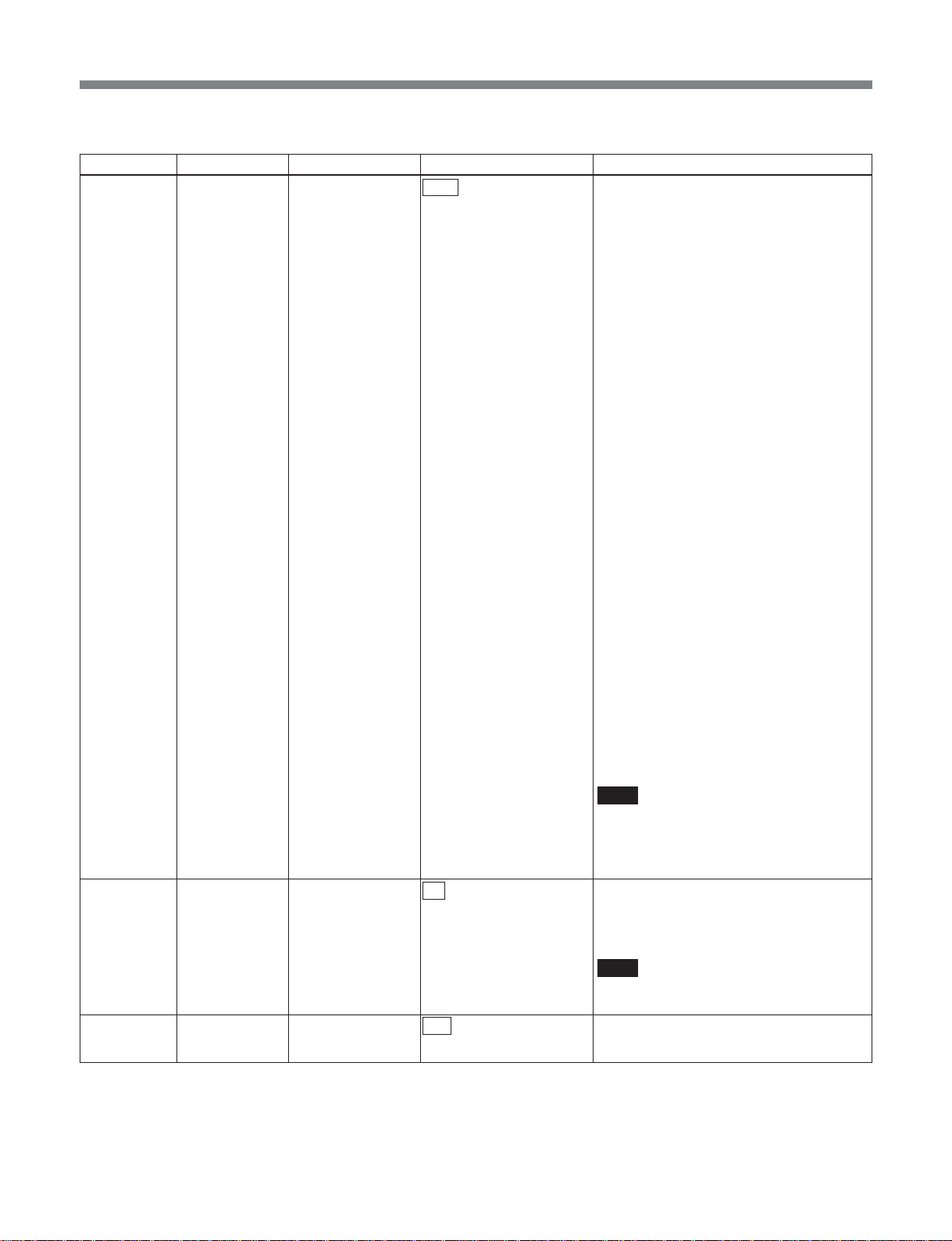
List of Menus
•In sdi_to_asi mode
Item number Category Item Arguments Function
C001 setup ref_source input The SDI input is used as reference for the
system clock.
The internal frame phase is determined by
following the frame phase of the input.
When the SDI is switched with a router
switch or similar, if the phase difference of
the input video is within ±10 µs, the
decoded video is switched without
transients appearing. If within the Window
(±1.5H), then there are no transients on the
ASI TS stream. If the Window is exceeded,
in order to follow the input, and reestablish
the frame phase lock, the TS stream is
interrupted for a few seconds.
Use this on condition that the input signal
is stable, in order to use a fixed latency.
internal The SDI input is used as reference for the
C005 setup tx_c_caption off Disables processing to transmit closed
on Enables processing to transmit closed
C011 setup chroma 422 This is 422P@ML.
420 This is MP@ML.
system clock.
The internal frame phase is determined
from the phase of the first video frame
input. At the time of SDI input switching,
therefore, with the relative phase of the
input frame and internal frame, the latency
fluctuates within a range of one frame.
Depending on the latency fluctuation, an
offset is applied to the audio PTS, and lip
sync is adjusted. Therefore, depending on
the phase difference between input frame
and internal frame, the audio stream may
be interrupted for several seconds.
With the switching timing, image
degradation occurs up to a maximum of
one frame, but transients do not appear on
the ASI TS stream.
Use this when using asynchronous SDI
switched with a router switch or similar, in
order to output a stable TS stream even if
there is degradation in the input signal.
Note
If the switching timing of the input signal is
outside the standard (SMPTE RP168),
there may be degradation of the TS stream
or image.
captions as Picture user data.
captions as Picture user data.
Note
This item is effective only when
video_system is 525.
49
Page 50
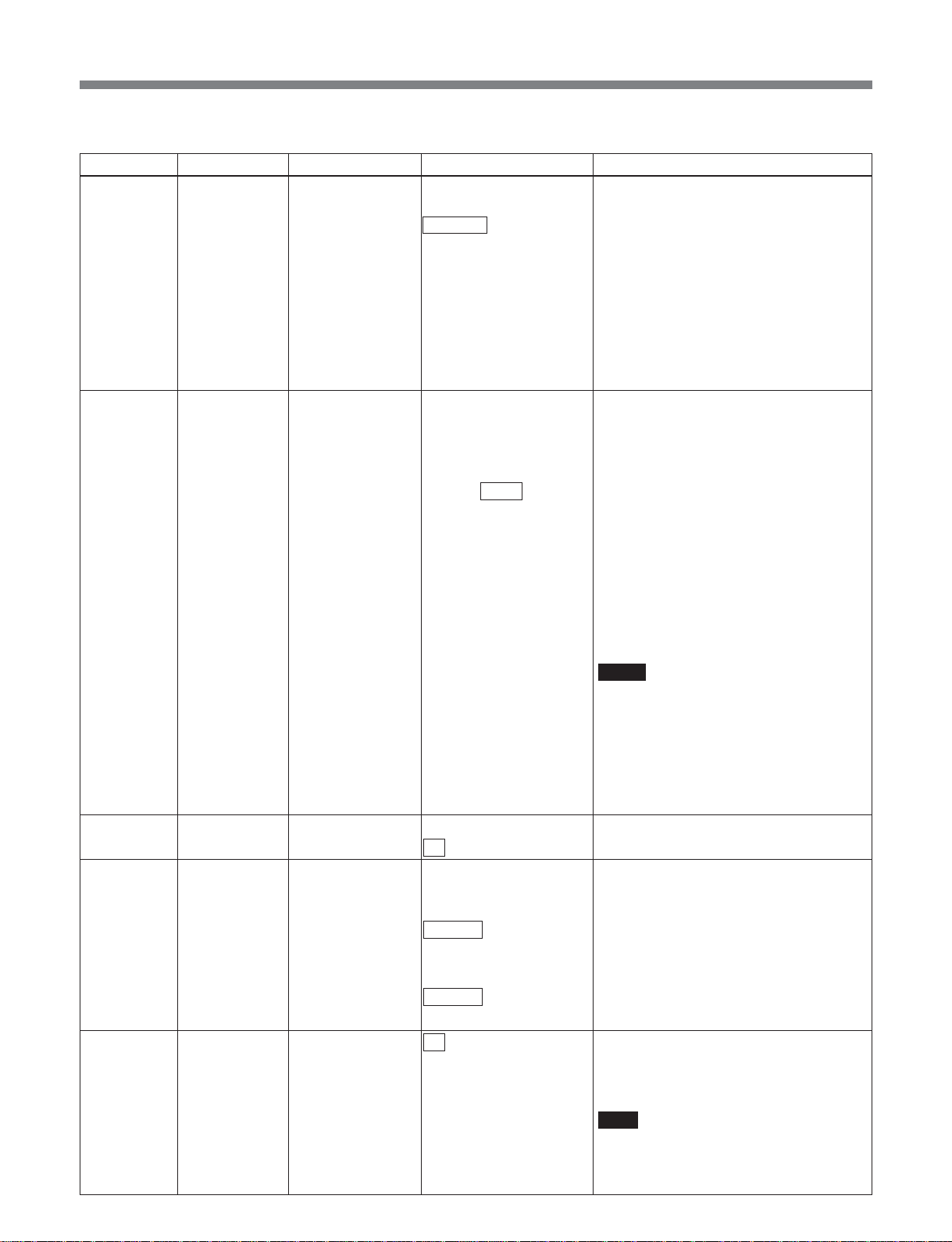
List of Menus
(In sdi_to_asi mode)
Item number Category Item Arguments Function
C012 setup video_encmode IMX This IMX encoding mode is characterized
NORMAL This encoding mode is M=3 with Long
LD This is a low delay mode, with All P Intra
NORMAL_BL This encoding mode is M=3 with Long
C013 setup video_rate auto The video ES bit rate is calculated
manual The video ES bit rate can be specified in
4.000 to 7.500 to 50.000
by All Intra CBG.
GOP CBR.
This yields a fixed latency, regardless of
the set bit rate.
slice.
GOP CBR.
This yields the minimum latency,
depending on the set bit rate.
automatically from the TS rate and audio
settings. An 'A' appears after the numeric
value.
units of 2 kbps. If a certain degree of error
occurs, this is controlled to be below the
setting value.
Argument unit: Mbps
When video_encmode is IMX:
30.000, 35.000, 40.000, 45.000, 50.000
Mbps
When chroma mode is 420:
4.000 to 15.000 Mbps
In other cases:
6.000 to 30.000 Mbps
Notes
• When the MSBA-20IP is installed, keep
ts_rate within 35.000 Mbps.
• If “N014: maintenance video_rate” is set
to “extended,” and video_encmode is
other than IMX, the minimum limit for
video_rate is 2 Mbps. Note, however, that
operation cannot be guaranteed at
present.
C014 setup scene_change off Disables scene change processing.
on Enables scene change processing.
C016 setup (Tx) pict_size Sets the picture size when encoding is
performed.
• When video_system is 525:
720x480 Sets the picture size to 720x480.
720x512 Sets the picture size to 720x512.
• When video_system is 625:
720x576 Sets the picture size to 720x576.
720x608 Sets the picture size to 720x608.
C017* setup (Tx) history_udata off History data for parameter referring re-
encoding is not included in the stream.
on History data for parameter referring re-
encoding is included in the stream.
Note
• This is supported as an option.
• This item is effective only when
video_encmode is normal.
50
Page 51

List of Menus
(In sdi_to_asi mode)
Item number Category Item Arguments Function
C018 setup (Tx) seq_hdr_cycle continuous Puts the sequence header on every
picture.
interstitial Puts the sequence header interstitially.
C021 setup audio_encmode MPEG Specifies the audio encoding as MPEG1
LayerII.
LPCM Specifies the audio encoding as linear
PCM (SMPET 302M).
C022 setup mpeg_ch12_mode stereo Specifies the audio mode for channels 1
and 2 as stereo.
dual Specifies the audio mode for channels 1
off Disables the audio for channels 1 and 2.
C023 setup mpeg_ch12_rate 128 Sets the bit rate of the audio for channels 1
192 Sets the bit rate of the audio for channels 1
256 Sets the bit rate of the audio for channels 1
384 Sets the bit rate of the audio for channels 1
C024 setup mpeg_ch34_mode stereo Specifies the audio mode for channels 3
dual Specifies the audio mode for channels 3
off Disables the audio for channels 3 and 4.
C025 setup mpeg_ch34_rate 128 Sets the bit rate of the audio for channels 3
192 Sets the bit rate of the audio for channels 3
256 Sets the bit rate of the audio for channels 3
384 Sets the bit rate of the audio for channels 3
C026 setup lpcm_channel 1-2 Specifies channels 1 and 2 for linear PCM.
3-4 Specifies channels 3 and 4 for linear PCM.
1-4 Specifies channels 1, 2, 3, and 4 for linear
1-8 Specifies channels 1, 2, 3, 4, 5, 6, 7, and 8
C027 setup lpcm_word_len 16 Sets the linear PCM sample word length to
20 Sets the linear PCM sample word length to
24 Sets the linear PCM sample word length to
C028 setup tx_audio_sg off Disables the internal test signal generator.
1 kHz Enables the internal test signal generator
silence Enables the internal test signal generator
and 2 as dual.
and 2 to 128 kbps.
and 2 to 192 kbps.
and 2 to 256 kbps.
and 2 to 384 kbps.
and 4 as stereo.
and 4 as dual.
and 4 to 128 kbps.
and 4 to 192 kbps.
and 4 to 256 kbps.
and 4 to 384 kbps.
PCM.
for linear PCM.
16 bits.
20 bits.
24 bits.
to output a 1 kHz sine wave.
to output silence.
51
Page 52
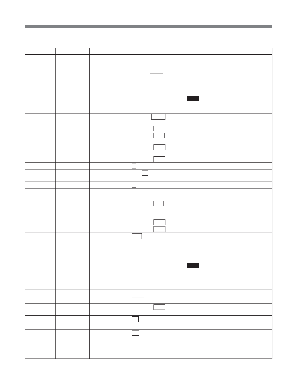
List of Menus
(In sdi_to_asi mode)
Item number Category Item Arguments Function
C061 setup ts_rate auto The TS rate is calculated automatically. An
manual The TS rate can be specified in units of
3.000 to 8.448 to 68.000
C062 setup tx_program_no 00001 to 00200 to 65535 Specifies the program number declared in
C063 setup video_pid 0x0010 to 00ff to 1ffe Specifies the video PID.
C064 setup mpeg_ch12_pid 0x0010 to 0101 to 1ffe Specifies the PID for MPEG audio
C065 setup mpeg_ch34_pid 0x0010 to 0102 to 1ffe Specifies the PID for MPEG audio
C066 setup lpcm_pid 0x0010 to 0100 to 1ffe Specifies the PID for linear PCM audio.
C067 setup pat_version 0 to 31 Specifies the PAT version number.
C068 setup pat_interval 1 to 33 to 100 Sets the PAT generation interval.
C069 setup pmt_version 0 to 31 Specifies the PMT version number.
C070 setup pmt_interval 1 to 33 to 100 Sets the PMT generation interval.
C071 setup pcr_pid 0x0010 to 00fe to 1ffe Specifies the PID for PCR.
C072 setup pcr_interval 1 to 33 to 100 Sets the PCR generation interval.
C073 setup program_map_pid 0x0010 to 00c8 to 1ffe Specifies the PID for PMT.
C074* setup network_pid 0x0010 to 0064 to 1ffe Specifies the PID for NIT.
C075 setup tx_packet_size 188 Specifies the output TS packet size as 188
204 Specifies the output TS packet size as 204
C076 setup tx_asi_mode packet Outputs output TS in packet mode.
burst Outputs output TS in burst mode.
C111 setup pri_pid_base 0x0010 to 00c0 to 1ff7 Specifies the base PID for transferring
C112* setup tx_umid off Disables UMID.
on Enables UMID. PID is “pri_pid_base” +0
C113 setup tx_line_data1 off Disables uncompressed line data
on Enables uncompressed line data
‘A’ appears after the numeric value.
1 kbps. If a certain degree of error occurs,
this is controlled to be below the setting
value.
Argument unit: Mbps
Note
When the MSBA-20IP is installed, keep
ts_rate within 35.000 Mbps.
PAT.
channels 1 and 2.
channels 3 and 4.
Unit: 1 ms
Unit: 1 ms
Unit: ms
bytes.
bytes.
(16 bytes of dummy data inlucluded.)
Note
When an MSBA-20IP board is installed,
the TS packet size for an MPEG stream
output through RTP is fixed at 188 bytes,
irrespective of this setting.
private data.
processing of 1st line.
processing of 1st line.
PID is “pri_pid_base” +1.
52
Page 53
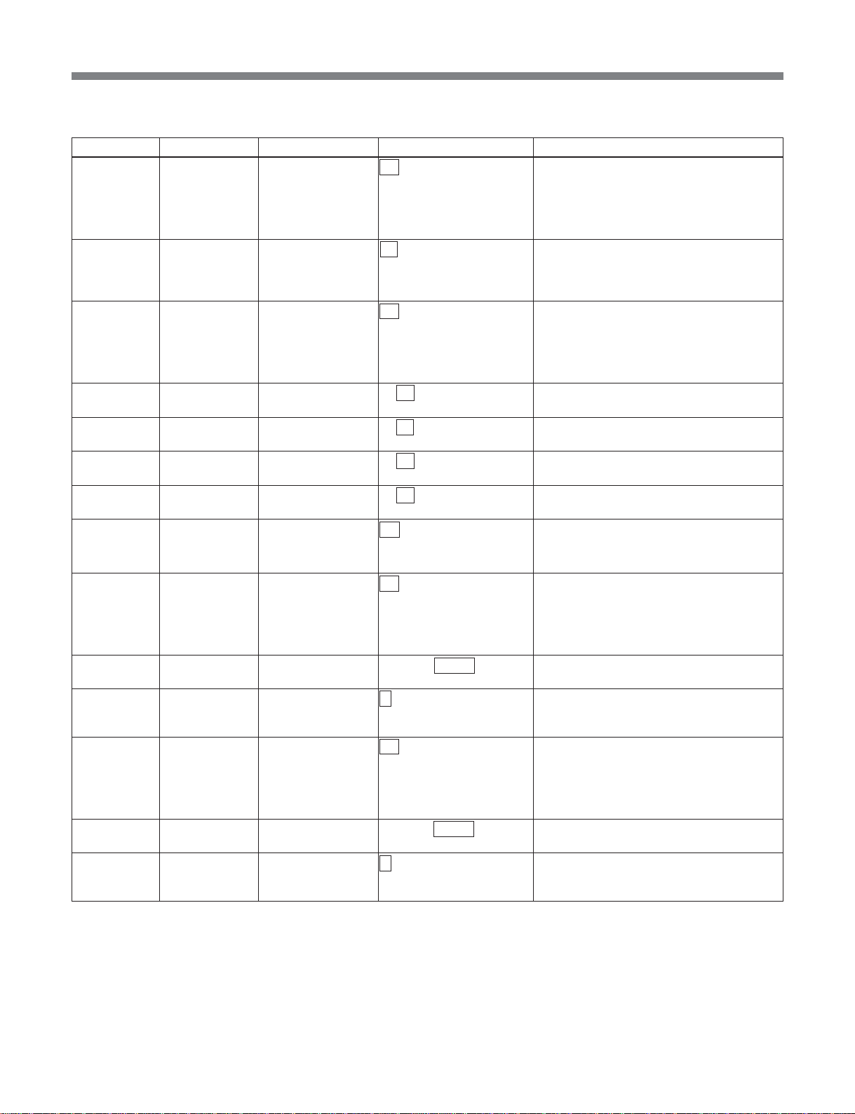
List of Menus
(In sdi_to_asi mode)
Item number Category Item Arguments Function
C114 setup tx_line_data2 off Disables uncompressed line data
on Enables uncompressed line data
C115 setup tx_line_base 12 to 21 Specifies the line number of the
C116* setup tx_vanc_data off Disables ancillary data processing in the
on Enables ancillary data processing in the
C117* setup tx_vanc1_did 0x 00 to ff Specifies the DID for vertical blanking
C118* setup tx_vanc1_sdid 0x 00 to ff Specifies the SDID for vertical blanking
C119* setup tx_vanc2_did 0x 00 to ff Specifies the DID for vertical blanking
C120* setup tx_vanc2_sdid 0x 00 to ff Specifies the SDID for vertical blanking
C121 setup tx_vitc_data off Disables VITC private data transfer.
on Enables VITC private data transfer.
C124* setup tx_udata1 off Disables getting user data1 from the UDP
on Enables getting User data1 from the UDP
C125* setup tx_udata1_port 05000 to 09000 to 65535 Sets the UDP port No. for picking up user
C126* setup tx_udata1_rate 1 to 30 Specifies rate for getting user data1 from
C127* setup tx_udata2 off Disables getting user data 2 from the UDP
on Enables getting user data 2 from the UDP
C128* setup tx_udata2_port 05000 to 09001 to 65535 Sets the UDP port No. for picking up user
C129* setup tx_udata2_rate 1 to 30 Specifies rate for getting user data 2 from
processing of 2nd line.
processing of 2nd line.
PID is “pri_pid_base” +1.
uncompressed line. This line and the
following line can be transferred as
uncompressed lines.
vertical blanking interval.
vertical blanking interval. PID is
“pri_pid_base” +2.
interval ancillary data.
interval ancillary data.
interval ancillary data.
interval ancillary data.
PID is “pri_pid_base” +3.
port, via the MSBA-20IP.
port, via the MSBA-20IP.
PID is “pri_pid_base” +6.
data1 from the MSBA-20IP.
the MSBA-20IP.
Unit: Mbps
port, via the MSBA-20IP.
port, via the MSBA-20IP.
PID is “pri_pid_base” +7.
data 2 from the MSBA-20IP.
the MSBA-20IP.
Unit: Mbps
53
Page 54

List of Menus
(In sdi_to_asi mode)
Item number Category Item Arguments Function
C998 setup cancel – Cancels a setup change before execution.
C999 setup init – Returns setup items to their factory default
– setup list – Displays the list set in setup.
Note
“C124” to “C129” are commands for outputting UDP
port user data to DVB-ASI (option functions), but are
not currently supported.
settings.
This is a special-purpose command for
RS232C/telnet operation.
54
Page 55
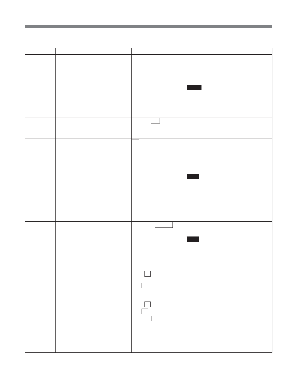
List of Menus
•In asi_to_sdi mode
Item number Category Item Arguments Function
C002 setup frame_sync_ref stream The STC obtained from the input stream is
used as the reference for SDI output.
ref_in The external analog composite input to the
REF IN connector is used as the reference
for SDI output.
Notes
• The analog reference must be a signal
such as black burst, with no amplitude
fluctuation.
• When ref_in is selected, the wordlength
for linear PCM audio samples is 16 bits.
C003 setup sync_phase 0x600 to 800 to 9ff Specifies any hexadecimal value from
0x600 to 0x9ff to enable fine adjustment of
the SDI output sync phase.
The adjustment range is ±18.9 µs.
C006 setup rx_c_caption off Disables processing to put closed captions
on Enables processing to put closed captions
C051 setup rx_audio_sg off Disables the internal test signal generator.
1 kHz Enables the internal test signal generator
silence Enables the internal test signal generator
C052 setup lip_sync –20.000 to +00.000 Carries out lip sync fine adjustment.
to +20.000 Unit: ms
C091 setup vitc_line1 off Disables processing to put VITC
10 to 18 to 20 (525) Specifies line number to hold VITC
7 to 21 to 22 (625)
C092 setup vitc_line2 off Disables processing to put VITC
10 to 18 to 20 (525) Specifies line number to hold VITC
7 to 21 to 22 (625)
C101 setup rx_program_no 00001 to 00200 to 65535 Specifies program number for decoding.
C102 setup rx_packet_size auto Automatically recognizes input TS packet
188
204 Sets input TS packet size to fixed 204
transmitted as Picture user data on base
band.
transmitted as Picture user data on base
band.
Note
This item is effective only when
video_system is 525.
to output a 1 kHz sine wave.
to output silence.
Note
When set to a negative value, note that
operation may not be guaranteed,
depending on the system status.
tarnsmitted as private data on base band.
tarnsmitted as private data.
tarnsmitted as private data on base band.
tarnsmitted as private data.
size.
Sets input TS packet size to fixed 188 bytes
bytes.
.
55
Page 56
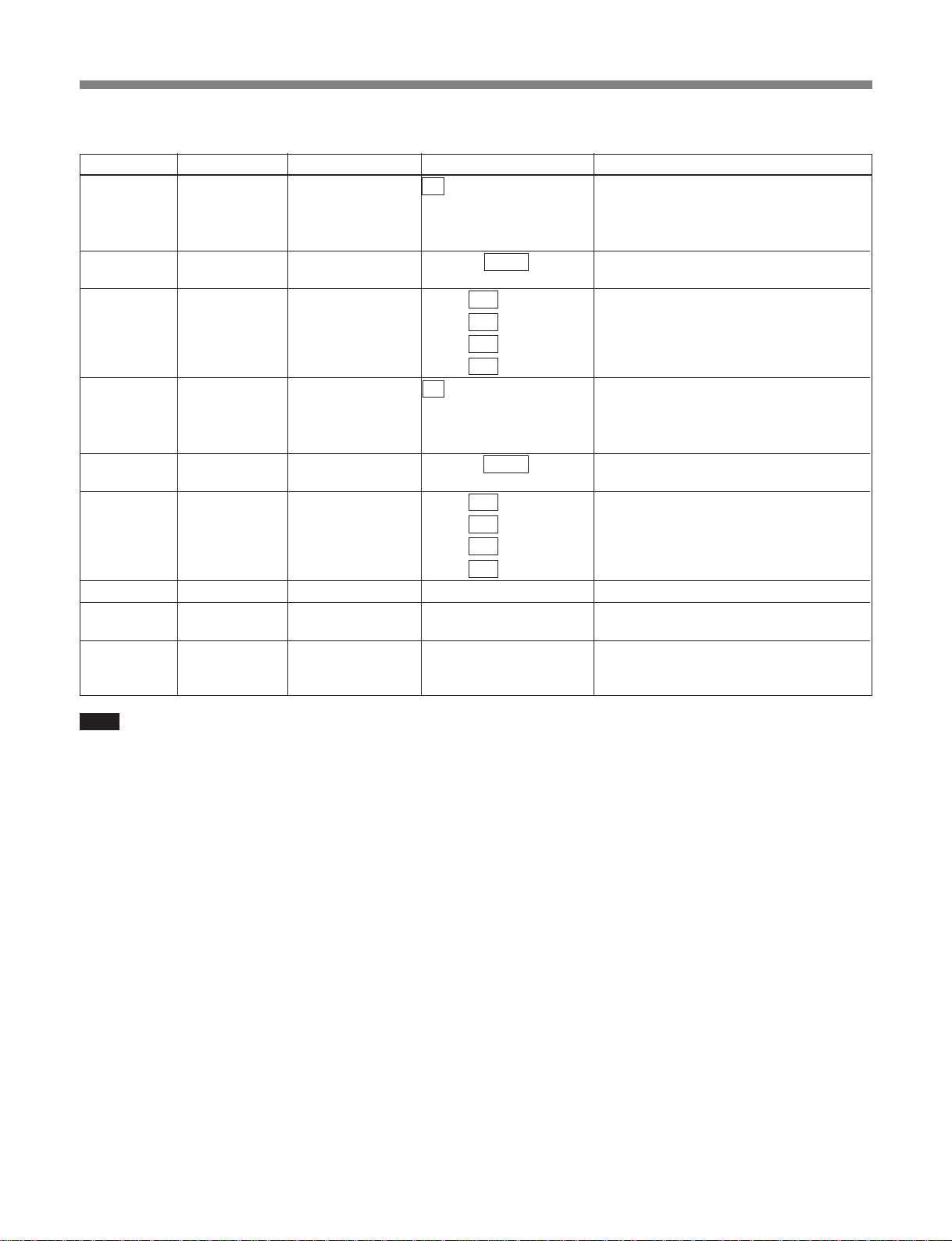
List of Menus
(In asi_to_sdi mode)
Item number Category Item Arguments Function
C141* setup rx_udata1 off Disables user data1 output from the UDP
on Enables user data1 output from the UDP
C142* setup dst_udata1_port 05000 to 09000 to 65535 Sets the UDP port No. for outputting user
C143* setup dst_udata1_ip 000 to 192 to 255. Sets the destination IP address for output
000 to 168 to 255.
000 to 001 to 255.
000 to 003 to 255
C144* setup rx_udata2 off Disables user data 2 output from the UDP
on Enables user data 2 output from the UDP
C145* setup dst_udata2_port 05000 to 09001 to 65535 Sets the UDP port No. for outputting user
C146* setup dst_udata2_ip 000 to 192 to 255. Sets the destination IP address for output
000 to 168 to 255.
000 to 001 to 255.
000 to 003 to 255
C998 setup cancel – Cancels a setup change before execution.
C999 setup init – Returns setup items to their factory default
– setup list – Displays the list set in setup.
port, via the MSBA-20IP.
port, via the MSBA-20IP.
data1 from the MSBA-20IP.
of user data1 from the MSBA-20IP.
port, via the MSBA-20IP.
port, via the MSBA-20IP.
data 2 from the MSBA-20IP.
of user data 2 from the MSBA-20IP.
settings.
This is a special-purpose command for
RS232C/telnet operation.
Note
“C141” to “C146” are commands for outputting
DVB-ASI user data to UDP port (option functions),
but are not currently supported.
56
Page 57
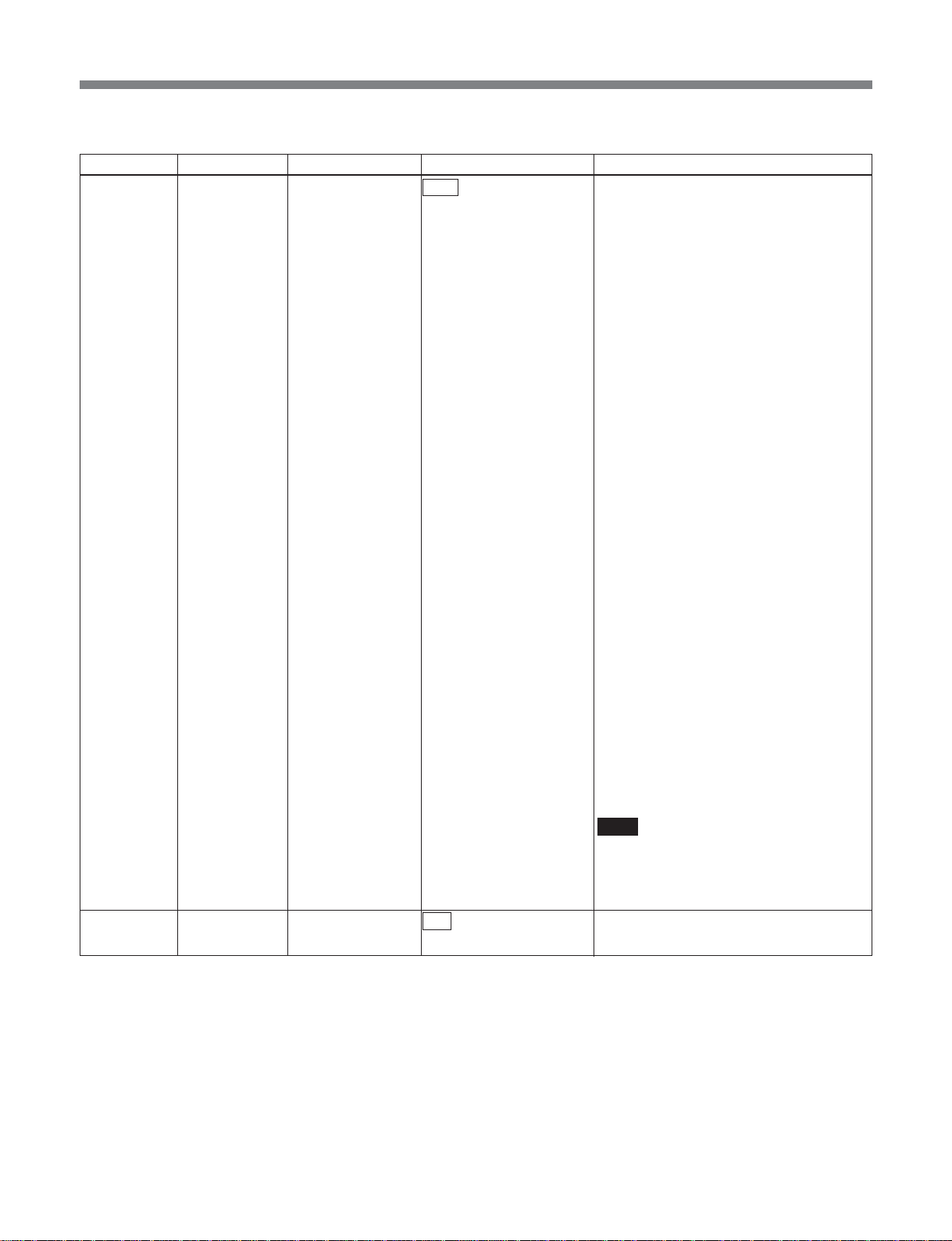
List of Menus
•In sdti-cp_to_asi mode
Item number Category Item Arguments Function
C001 setup ref_source input The SDTI-CP input is used as reference for
internal The SDTI-CP input is used as reference for
C011 setup chroma 422 This is 422P@ML.
420 This is MP@ML.
the system clock.
The internal frame phase is determined by
following the frame phase of the input.
When the SDTI-CP is switched with a
router switch or similar, if the phase
difference of the input video is within
±10 µs, the decoded video is switched
without transients appearing. If within the
Window (±1.5H), then there are no
transients on the ASI TS stream. If the
Window is exceeded, in order to follow the
input and reestablish the frame phase lock,
the TS stream is interrupted for a few
seconds.
Use this on condition that the input signal
is stable, in order to use a fixed latency.
the system clock.
The internal frame phase is determined
from the phase of the first video frame
input. At the time of SDTI-CP input
switching, therefore, with the relative phase
of the input frame and internal frame, the
latency fluctuates within a range of one
frame. Depending on the latency
fluctuation, an offset is applied to the audio
PTS, and lip sync is adjusted. Therefore,
depending on the phase difference
between input frame and internal frame,
the audio stream may be interrupted for
several seconds.
With the switching timing, image
degradation occurs up to a maximum of
one frame, but transients do not appear on
the ASI TS stream.
Use this when using asynchronous SDI
switched with a router switch or similar, in
order to output a stable TS stream even if
there is degradation in the input signal.
Note
If the switching timing of the input signal is
outside the standard (SMPTE RP168),
there may be degradation of the TS stream
or image.
57
Page 58
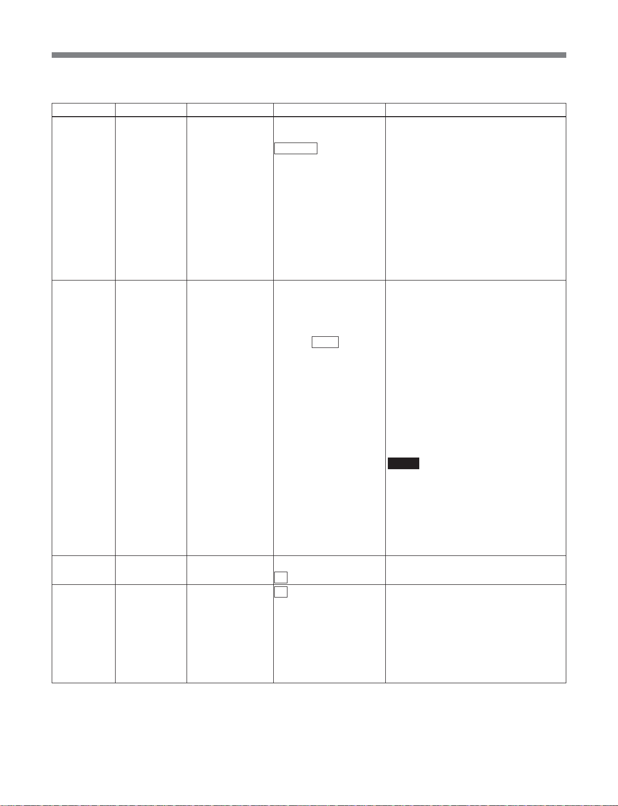
List of Menus
(In sdti-cp_to_asi mode)
Item number Category Item Arguments Function
C012 setup video_encmode IMX This IMX encoding mode is characterized
by All Intra CBG.
NORMAL This encoding mode is M=3 with Long
GOP CBR.
This yields a fixed latency, regardless of
the set bit rate.
LD This is a low delay mode, with All P Intra
NORMAL_BL This encoding mode is M=3 with Long
REENCODE* This is a reencode mode which reuses the
C013 setup video_rate auto The video ES bit rate is calculated
manual The video ES bit rate can be specified in
4.000 to 7.500 to 50.000 units of 2 kbps. If a certain degree of error
C014 setup scene_change off Disables scene change processing.
on Enables scene change processing.
C015* setup history off Invalidates encoding by reuse of the
part Validates encoding by partial reuse of the
full Validates encoding by entire reuse of the
slice.
GOP CBR.
This yields the minimum latency,
depending on the set bit rate.
history partially or entirely.
automatically from the TS rate and audio
settings. An ‘A’ appears after the numeric
value.
occurs, this is controlled to be below the
setting value.
Argument unit: Mbps
When video_encmode is IMX:
30.000, 35.000, 40.000, 45.000, 50.000
Mbps
When chroma mode is 420:
4.000 to 15.000 Mbps
In other cases:
6.000 to 30.000 Mbps
Notes
• When the MSBA-20IP is installed, keep
ts_rate within 35.000Mbps.
• If “N014: maintenance video_rate” is set
to “extended,” and video_encmode is
other than IMX, the minimum limit for
video_rate is 2 Mbps. Note, however, that
operation cannot be guaranteed at
present.
history.
When video_encmode is REENCODE, the
setting “part” or “full” can be selected.
history.
history.
58
Page 59

List of Menus
(In sdti-cp_to_asi mode)
Item number Category Item Arguments Function
C016 setup (Tx) pict_size Sets the picture size when encoding is
performed.
• When video_system is 525:
720x480 Sets the picture size to 720x480.
720x512 Sets the picture size to 720x512.
• When video_system is 625:
720x576 Sets the picture size to 720x576.
720x608 Sets the picture size to 720x608.
C018 setup (Tx) seq_hdr_cycle continuous Puts the sequence header on every
picture.
interstitial Puts the sequence header interstitially.
C021 setup audio_encmode MPEG Specifies the audio encoding as MPEG1
LayerII.
LPCM Specifies the audio encoding as Linear
PCM (SMPTE 302M).
C022 setup mpeg_ch12_mode stereo Specifies the audio mode for channels 1
and 2 as stereo.
dual Specifies the audio mode for channels 1
and 2 as dual.
off Disables the audio for channels 1 and 2.
C023 setup mpeg_ch12_rate 128 Sets the bit rate of the audio for channels 1
and 2 to 128 kbps.
192 Sets the bit rate of the audio for channels 1
and 2 to 192 kbps.
256 Sets the bit rate of the audio for channels 1
and 2 to 256 kbps.
384 Sets the bit rate of the audio for channels 1
and 2 to 384 kbps.
C024 setup mpeg_ch34_mode stereo Specifies the audio mode for channels 3
dual Specifies the audio mode for channels 3
off Disables the audio for channels 3 and 4.
C025 setup mpeg_ch34_rate 128 Sets the bit rate of the audio for channels 3
192 Sets the bit rate of the audio for channels 3
256 Sets the bit rate of the audio for channels 3
384 Sets the bit rate of the audio for channels 3
C026 setup lpcm_channel 1-2 Specifies channels 1 and 2 for linear PCM.
3-4 Specifies channels 3 and 4 for linear PCM.
1-4 Specifies channels 1, 2, 3, and 4 for linear
1-8 Specifies channels 1, 2, 3, 4, 5, 6, 7, and 8
and 4 as stereo.
and 4 as dual.
and 4 to 128 kbps.
and 4 to 192 kbps.
and 4 to 256 kbps.
and 4 to 384 kbps.
PCM.
for linear PCM.
59
Page 60
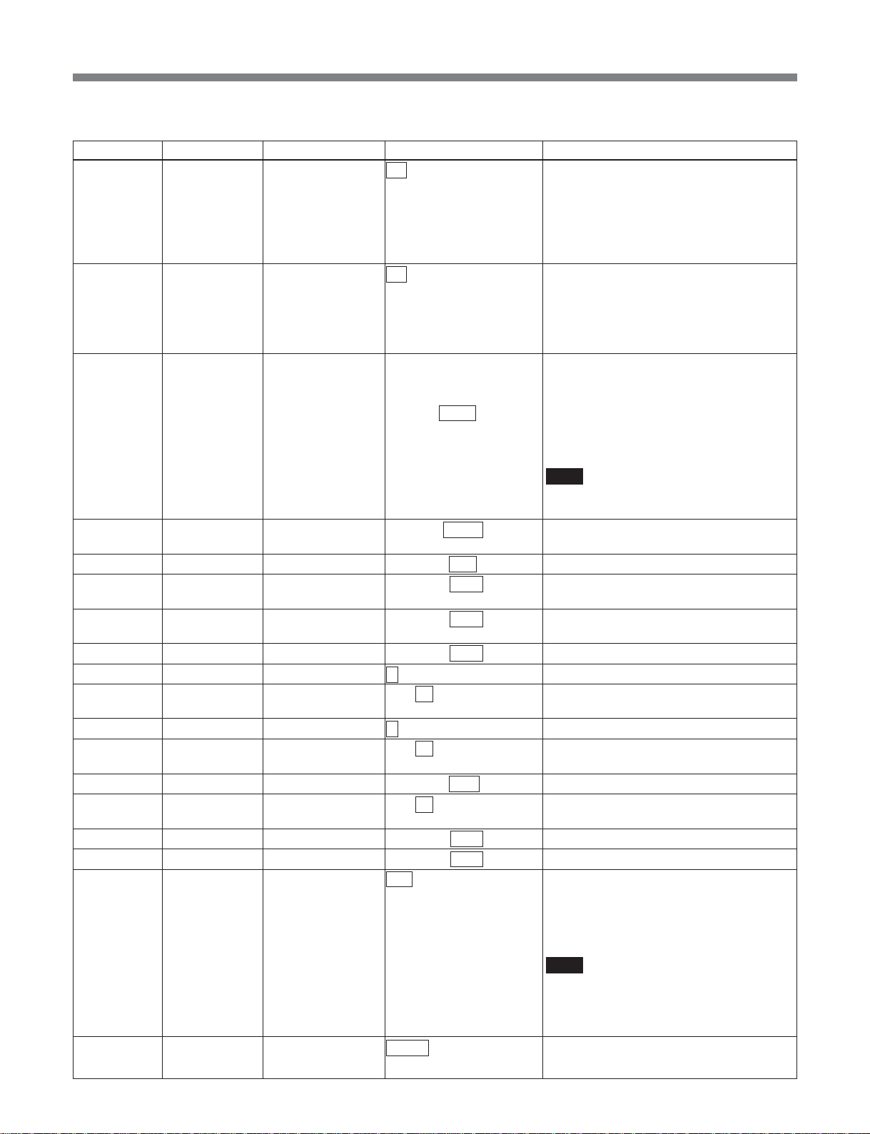
List of Menus
(In sdti-cp_to_asi mode)
Item number Category Item Arguments Function
C027 setup lpcm_word_len 16 Sets the linear PCM sample word length to
20 Sets the linear PCM sample word length to
24 Sets the linear PCM sample word length to
C028 setup tx_audio_sg off Disables the internal test signal generator.
1 kHz Enables the internal test signal generator
silence Enables the internal test signal generator
C061 setup ts_rate auto The TS rate is calculated automatically. An
manual The TS rate can be specified in units of
3.000 to 8.448 to 68.000 1 kbps. If a certain degree of error occurs,
C062 setup tx_program_no 00001 to 00200 to 65535 Specifies the program number declared in
C063 setup video_pid 0×0010 to 00ff to 1ffe Specifies the video PID.
C064 setup mpeg_ch12_pid 0×0010 to 0101 to 1ffe Specifies the PID for MPEG audio
C065 setup mpeg_ch34_pid 0×0010 to 0102 to 1ffe Specifies the PID for MPEG audio
C066 setup lpcm_pid 0×0010 to 0100 to 1ffe Specifies the PID for linear PCM audio.
C067 setup pat_version 0 to 31 Specifies the PAT version number.
C068 setup pat_interval 1 to 33 to 100 Sets the PAT generation interval.
C069 setup pmt_version 0 to 31 Specifies the PMT version number.
C070 setup pmt_interval 1 to 33 to 100 Sets the PMT generation interval.
C071 setup pcr_pid 0×0010 to 00fe to 1ffe Specifies the PID for PCR.
C072 setup pcr_interval 1 to 33 to 100 Sets the PCR generation interval.
C073 setup program_map_pid 0×0010 to 00c8 to 1ffe Specifies the PID for PMT.
C074* setup network_pid 0×0010 to 0064 to 1ffe Specifies the PID for NIT.
C075 setup tx_packet_size 188 Specifies the output TS packet size as 188
204 Specifies the output TS packet size as 204
C076 setup tx_asi_mode packet Outputs output TS in packet mode.
burst Outputs output TS in burst mode.
16 bits.
20 bits.
24 bits.
to output a 1 kHz sine wave.
to output silence.
‘A’ appears after the numeric value.
this is controlled to be below the setting
value.
Argument unit :Mbps
Note
When the MSBA-20IP is installed, keep
ts_rate within 35.000 Mbps.
PAT.
channels 1 and 2.
channels 3 and 4.
Unit: 1 ms
Unit: 1 ms
Unit: ms
bytes.
bytes.
(16 bytes of dummy data inlucluded.)
Note
When an MSBA-20IP board is installed,
the TS packet size for an MPEG stream
output through RTP is fixed at 188 bytes,
irrespective of this setting.
60
Page 61
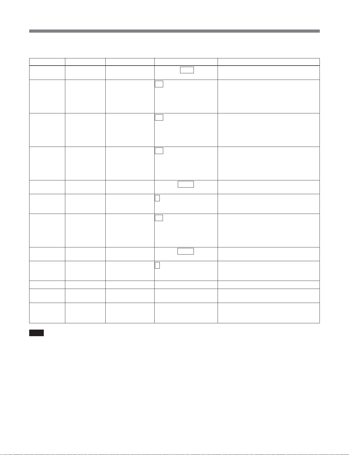
List of Menus
(In sdti-cp_to_asi mode)
Item number Category Item Arguments Function
C111* setup pri_pid_base 0×0010 to 00c0 to 1ff7 Specifies the base PID for transferring
C122* setup tx_system_item off Invalidates the transmission of SDTI-CP
on Validates the transmission of SDTI-CP
C123* setup tx_aux_item off Invalidates the transmisstion of SDTI-CP
on Validates the transmisstion of SDTI-CP
C124* setup tx_udata1 off Disables getting user data1 from the UDP
on Enables getting user data1 from the UDP
C125* setup tx_udata1_port 05000 to 09000 to 65535 Sets the UDP port No. for picking up user
C126* setup tx_udata1_rate 1 to 30 Specifies rate for getting user data1 from
C127* setup tx_udata2 off Disables getting user data 2 from the UDP
on Enables getting user data 2 from the UDP
C128* setup tx_udata2_port 05000 to 09001 to 65535 Sets the UDP port No. for picking up user
C129* setup tx_udata2_rate 1 to 30 Specifies Rate for getting user data 2 from
C998 setup cancel – Cancels a setup change before execution.
C999 setup init – Returns setup items to their factory default
– setup list – Displays the list set in setup.
private data.
“system_item”.
“system_item”.
PID is “pri_pid_base”+4.
“aux_item”.
“aux_item”.
PID is “pri_pid_base”+5.
port, via the MSBA-20IP.
port, via the MSBA-20IP.
PID is “pri_pid_base” +6.
data1 from the MSBA-20IP.
the MSBA-20IP.
Unit: Mbps
port via the MSBA-20IP.
port via the MSBA-20IP.
PID is “pri_pid_base” +7.
data 2 from the MSBA-20IP.
the MSBA-20IP.
Unit: Mbps
settings.
This is a special-purpose command for
RS232C/telnet operation.
Note
“C124” to “C129” are commands for outputting UDP
port user data to DVB-ASI (option functions), but are
not currently supported.
61
Page 62
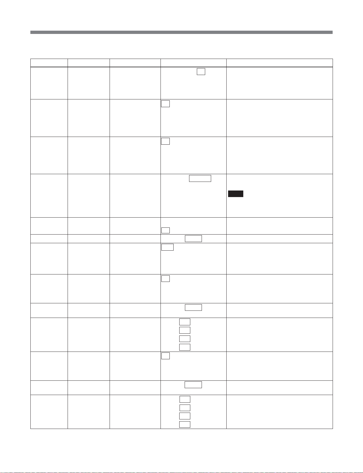
List of Menus
•In asi_to_sdti-cp mode
Item number Category Item Arguments Function
C013 setup video_rate 30, 35, 40, 45, 50 The video ES bit rate can be specified in
units of 5 Mbps.
The rate control method is All intra CBG
(IMX).
Unit: Mbps
C015* setup history off Invalidates history insertion into video ES.
part Validates partial history insertion into video
ES.
full Validates entire history insertion into video
ES.
C051 setup rx_audio_sg off Disables the internal test signal generator.
1 kHz Enables the internal test signal generator
to output a 1 kHz sine wave.
silence Enables the internal terÙ(signal generator
to output silence.
C052 setup lip_sync –20.000 to +00.000 to Carries out lip sync fine adjustment.
+20.000 Unit: ms
Note
When set to a negative value, note that
operation may not be guaranteed,
depending on the system status.
C081 setup fec_mode off Invalidates SDTI-CP FEC.
on Validates SDTI-CP FEC.
C101 setup rx_program_no 00001 to 00200 to 65535 Specifies program number for decoding.
C102 setup rx_packet_size auto Automatically recognizes input TS packet
size.
188
204
C141* setup rx_udata1 off Disables user data 1 output from the UDP
on Enables user data 1 output from the UDP
C142* setup dst_udata1_port 05000 to 09000 to 65535 Set the UDP port No. for outputting user
C143* setup dst_udata1_ip 000 to 192 to 255. Sets the destination IP address for output
000 to 168 to 255.
000 to 001 to 255.
000 to 003 to 255
C144* setup rx_udata2 off Disables user data 2 output from the UDP
on Enables user data 2 output from the UDP
C145* setup dst_udata2_port 05000 to 09001 to 65535 Sets the UDP port No. for outputting user
C146* setup dst_udata2_ip 000 to 192 to 255. Sets the destination IP address for
000 to 168 to 255.
000 to 001 to 255.
000 to 003 to 255
Sets input TS packet size to fixed 188 bytes.
Sets input TS packet size to fixed 204 bytes.
port, via the MSBA-20IP.
port, via the MSBA-20IP.
data 1 from the MSBA-20IP.
of user data1 from the MSBA-20IP.
port, via the MSBA-20IP.
port, via the MSBA-20IP.
data 2 from the MSBA-20IP.
outputting user
20IP.
data 2 from the MSBA-
62
Page 63

List of Menus
(In asi_to_sdti-cp mode)
Item number Category Item Arguments Function
C998 setup cancel – Cancels a setup change before execution.
C999 setup init – Returns setup items to their factory default
settings.
– setup list – Displays the list set in setup.
This is a special-purpose command for
RS232C/telnet operation.
Note
“C141” to “C146” are commands for outputting DVBASI user data to UDP port (option functions), but are
not currently supported.
63
Page 64
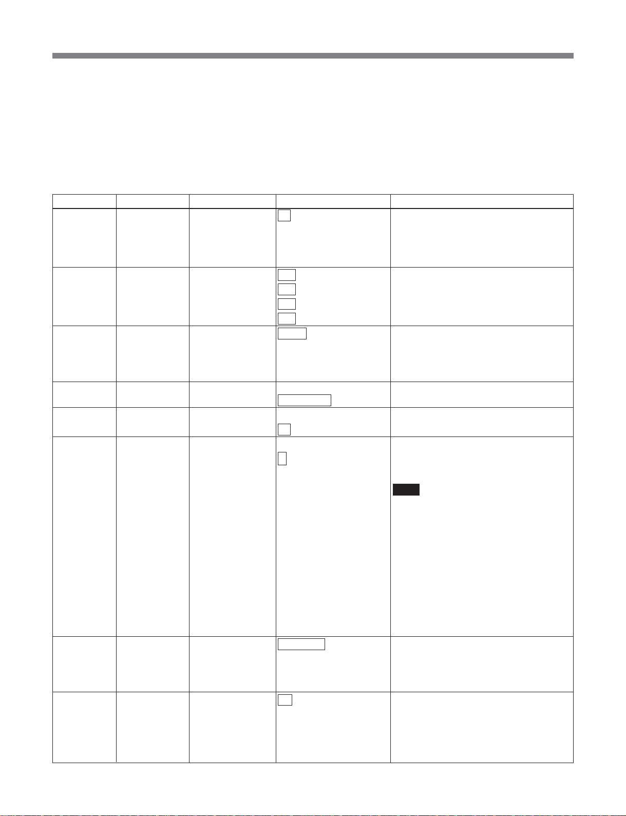
List of Menus
E:link_mng menu
In this menu, you set setting values that depend on the
operating mode. Depending on the operating mode set
in the “B:mode” menu, the setting items corresponding
to the mode are selected. If the arguments are omitted,
the current setting is given as the return value.
•In tx-rx mode
Item number Category Item Arguments Function
E001** link_mng (Tx) rtp_tx off Invalidates MPEG streaming output
through the MSBA-20IP.
on Validate MPEG streaming output through
the MSBA-20IP. Streaming supports up to
35 Mbps as a TS rate.
E002** link_mng (Tx) rtp_tx_ip 000 to 255. Sets the destination IP address for MPEG
000 to 255.
000 to 255.
000 to 255
E003** link_mng (Tx) rtp_tx_port 50000 to 65534 Sets the UDP port No. for MPEG
E004** link_mng (Tx) rtp_tx_ssrc 0x00000000 to Sets “SSRC” which is member of RTCP.
0x01234567 to 0xffffffff Default value is 0x01234567.
E005** link_mng (Tx) rtp_tx_fec_mode off Invalidates Error collection.
on Validate Error collection.
E006** link_mng (Tx) rtp_tx_format 1 Selects Streaming packet format.
2 1: 1 TS packet per IPdatagram
E007** link_mng (Tx) rtp_tx_cname MSB-2000 Sets “CNAME” which is member of RTCP.
E021** link_mng (Rx) rtp_rx off Invalidates MPEG streaming input through
on Validates MPEG streaming input through
streaming output through the MSBA-20IP
For Multicast transmission, select in the
range 224.0.0.0 to 239.255.255.255.
streaming output through the MSBA-20IP.
The port No. can only be set to an even
number. The RTCP port No. is the setting
value plus one.
2: 6 TS packets per IP datagram
Note
It is recommended to use a setting of “2”
with less overhead. Avoid using both “1”
and “2” on the same network.
The IP transfer bandwidth required for
each TS rate is as follows.
• For a setting of “1” when “C165” is “off”:
141% of TS rate
• For a setting of “1” when “C165” is “on”:
156% of TS rate
• For a setting of “2” when “C165” is “off”:
107% of TS rate
• For a setting of “2” when “C165” is “on”:
122% of TS rate
Default CNAME here is “MSB-2000”.
Maximum length is 15 characters.The
characters that can be used are ASCII
codes in the range 0x21 to 0x7d.
the MSBA-20IP.
the MSBA-20IP instead of ASI input
Streaming supports up to 35 Mbps as a TS
rate.
.
64
Page 65
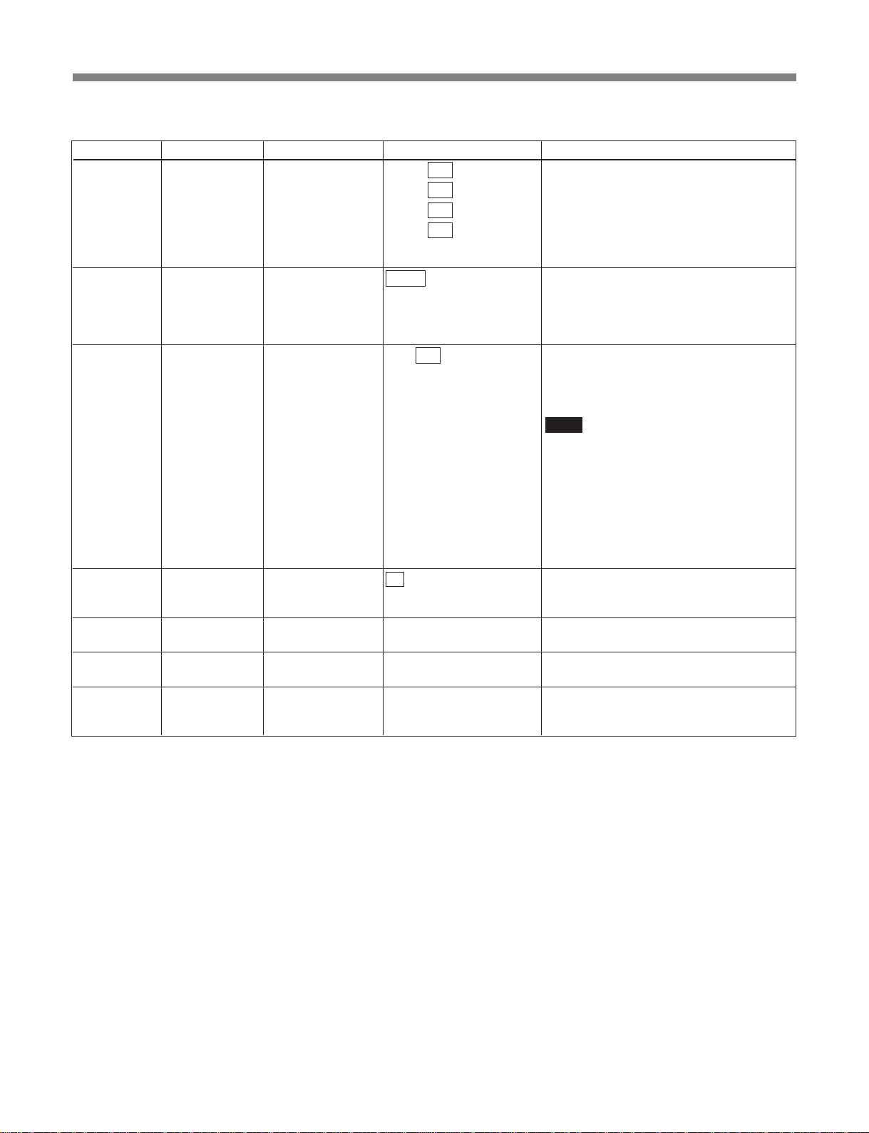
List of Menus
(In tx-rx mode)
Item number Category Item Arguments Function
E022** link_mng (Rx) rtp_rx_ip 000 to 255 . Sets the source IP address for MPEG
000 to 255 .
000 to 255 .
000 to 255
E023** link_mng (Rx) rtp_rx_port 50000 to 65534 Sets the UDP port No. which should be
E024** link_mng (Rx) buffer_depth 0 to 100 to 2000 Specifies the MSBA-20IP receiving buffer
E031** link_mng (Tx/Rx) tos_field 00 to ff Specifies the value (8 bits) of the Tos field
E998** link_mng cancel – Cancels a link_mng change before
E999** link_mng init – Returns link_mng items to their factory
–** link_mng list – Displays the list set in link_mng.
stream input through MSBA-20IP.
If set to 255.255.255.255 data will be
received regardless of the MPEG stream
input source IP address. However, to
receive multicasts, set in the range4.0.0.0
to 239.255.255.255.
obtained as an MPEG streaming data
through the MSBA-20IP. The port No. can
only be set to an even number. The RTCP
port No. is the setting value plus one.
depth.
The range of settings is from 0 to 2000 ms
(in 1 ms increments).
Note
Normally use the default setting of “100.”
The receiving buffer depth range ensuring
a correct operation depends on the setting
in “C061:ts_rate”, “C165:rtp_tx_fec_mode”
and “C166:rtp_tx_format” on the
transmitting side, so care is required when
changing the settings.
For details, refer to the Maintenance
Manual.
(Diff serve field) of IP packets output by the
MSBA-20IP.
execution.
default settings.
This is a special-purpose command for
RS232C/telnet operation.
65
Page 66
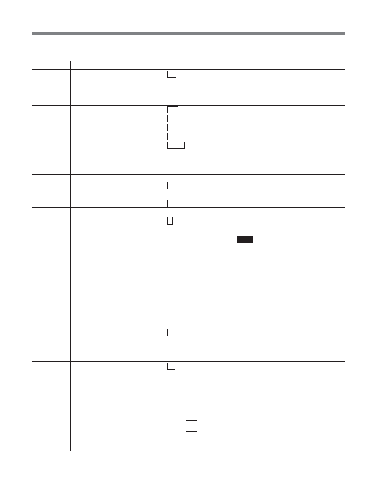
List of Menus
•In tx-rx (cm) mode
Item number Category Item Arguments Function
E001** link_mng (Tx) rtp_tx off Invalidates MPEG streaming output
through the MSBA-20IP.
on Validate MPEG streaming output through
E002** link_mng (Tx) rtp_tx_ip 000 to 255. Sets the destination IP address for MPEG
000 to 255.
000 to 255.
000 to 255
E003** link_mng (Tx) rtp_tx_port 50000 to 65534 Sets the UDP port No. for MPEG
E004** link_mng (Tx) rtp_tx_ssrc 0x00000000 to Sets “SSRC” which is member of RTCP.
0x01234567 to 0xffffffff Default value is 0x01234567.
E005** link_mng (Tx) rtp_tx_fec_mode off Invalidates Error collection.
on Validate Error collection.
E006** link_mng (Tx) rtp_tx_format 1 Selects Streaming packet format.
2 1: 1 TS packet per IPdatagram
E007** link_mng (Tx) rtp_tx_cname MSB-2000 Sets “CNAME” which is member of RTCP.
E021** link_mng (Rx) rtp_rx off Invalidates MPEG streaming input through
on Validates MPEG streaming input through
E022** link_mng (Rx) rtp_rx_ip 000 to 255 . Sets the source IP address for MPEG
000 to 255 .
000 to 255 .
000 to 255
the MSBA-20IP. Streaming supports up to
35 Mbps as a TS rate.
streaming output through the MSBA-20IP.
For Multicast transmission, select in the
range 224.0.0.0 to 239.255.255.255.
streaming output through the MSBA-20IP.
The port No. can only be set to an even
number. The RTCP port No. is the setting
value plus one.
2: 6 TS packets per IP datagram
Note
It is recommended to use a setting of “2”
with less overhead. Avoid using both “1”
and “2” on the same network.
The IP transfer bandwidth required for
each TS rate is as follows.
• For a setting of “1” when “C165” is “off”:
141% of TS rate
• For a setting of “1” when “C165” is “on”:
156% of TS rate
• For a setting of “2” when “C165” is “off”:
107% of TS rate
• For a setting of “2” when “C165” is “on”:
122% of TS rate
Default CNAME here is “MSB-2000”.
Maximum length is 15 characters.The
characters that can be used are ASCII
codes in the range 0x21 to 0x7d.
the MSBA-20IP.
the MSBA-20IP instead of ASI input
Streaming supports up to 35 Mbps as a TS
rate.
stream input through MSBA-20IP.
If set to 255.255.255.255 data will be
received regardless of the MPEG stream
input source IP address. However, to
receive multicasts, set in the range4.0.0.0
to 239.255.255.255.
66
Page 67
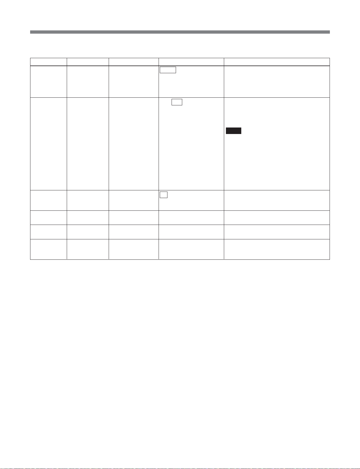
List of Menus
(In tx-rx (cm) mode)
Item number Category Item Arguments Function
E023** link_mng (Rx) rtp_rx_port 50000 to 65534 Sets the UDP port No. which should be
obtained as an MPEG streaming data
through the MSBA-20IP. The port No. can
only be set to an even number. The RTCP
port No. is the setting value plus one.
E024** link_mng (Rx) buffer_depth 0 to 100 to 2000 Specifies the MSBA-20IP receiving buffer
depth.
The range of settings is from 0 to 2000 ms
(in 1 ms increments).
Note
Normally use the default setting of “100.”
The receiving buffer depth range ensuring
a correct operation depends on the setting
in “C061:ts_rate”, “C165:rtp_tx_fec_mode”
and “C166:rtp_tx_format” on the
transmitting side, so care is required when
changing the settings.
For details, refer to the Maintenance
Manual.
E031** link_mng (Tx/Rx) tos_field 00 to ff Specifies the value (8 bits) of the Tos field
(Diff serve field) of IP packets output by the
MSBA-20IP.
E998** link_mng cancel – Cancels a link_mng change before
execution.
E999** link_mng init – Returns link_mng items to their factory
default settings.
–** link_mng list – Displays the list set in link_mng.
This is a special-purpose command for
RS232C/telnet operation.
67
Page 68
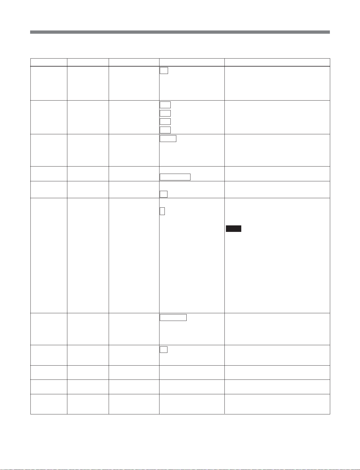
List of Menus
•In sdi_to_asi mode
Item number Category Item Arguments Function
E001** link_mng (Tx) rtp_tx off Invalidates MPEG streaming output
through the MSBA-20IP.
on Validate MPEG streaming output through
E002** link_mng (Tx) rtp_tx_ip 000 to 255. Sets the destination IP address for MPEG
000 to 255.
000 to 255.
000 to 255
E003** link_mng (Tx) rtp_tx_port 50000 to 65534 Sets the UDP port No. for MPEG
E004** link_mng (Tx) rtp_tx_ssrc 0x00000000 to Sets “SSRC” which is member of RTCP.
0x01234567 to 0xffffffff Default value is 0x01234567.
E005** link_mng (Tx) rtp_tx_fec_mode off Invalidates Error collection.
on Validate Error collection.
E006** link_mng (Tx) rtp_tx_format 1 Selects Streaming packet format.
2 1: 1 TS packet per IPdatagram
E007** link_mng (Tx) rtp_tx_cname MSB-2000 Sets “CNAME” which is member of RTCP.
E031** link_mng (Tx/Rx) tos_field 00 to ff Specifies the value (8 bits) of the Tos field
E998** link_mng cancel – Cancels a link_mng change before
E999** link_mng init – Returns link_mng items to their factory
–** link_mng list – Displays the list set in link_mng.
the MSBA-20IP. Streaming supports up to
35 Mbps as a TS rate.
streaming output through the MSBA-20IP
For Multicast transmission, select in the
range 224.0.0.0 to 239.255.255.255.
streaming output through the MSBA-20IP.
The port No. can only be set to an even
number. The RTCP port No. is the setting
value plus one.
2: 6 TS packets per IP datagram
Note
It is recommended to use a setting of “2”
with less overhead. Avoid using both “1”
and “2” on the same network.
The IP transfer bandwidth required for
each TS rate is as follows.
• For a setting of “1” when “C165” is “off”:
141% of TS rate
• For a setting of “1” when “C165” is “on”:
156% of TS rate
• For a setting of “2” when “C165” is “off”:
107% of TS rate
• For a setting of “2” when “C165” is “on”:
122% of TS rate
Default CNAME here is “MSB-2000”.
Maximum length is 15 characters.The
characters that can be used are ASCII
codes in the range 0x21 to 0x7d.
(Diff serve field) of IP packets output by the
MSBA-20IP.
execution.
default settings.
This is a special-purpose command for
RS232C/telnet operation.
.
68
Page 69
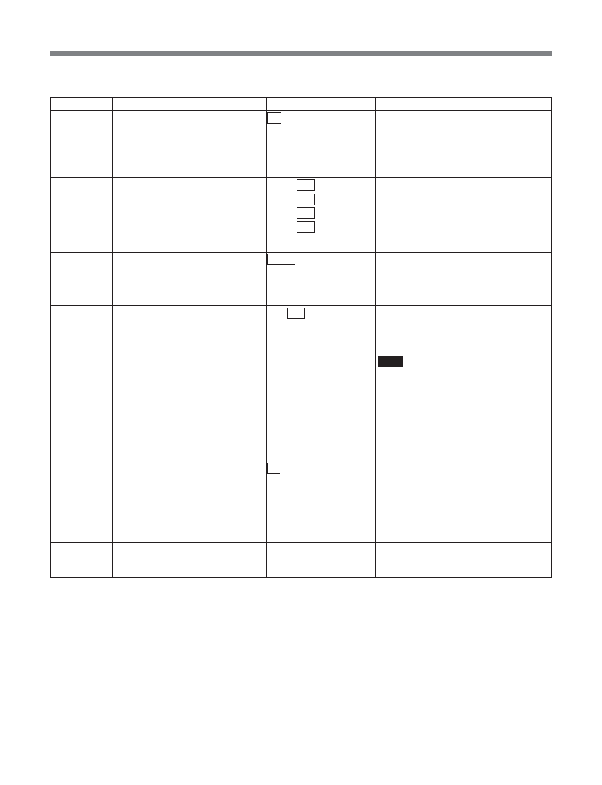
List of Menus
•In asi_to_sdi mode
Item number Category Item Arguments Function
E021** link_mng (Rx) rtp_rx off Invalidates MPEG streaming input through
the MSBA-20IP.
on Validates MPEG streaming input through
E022** link_mng (Rx) rtp_rx_ip 000 to 255 . Sets the source IP address for MPEG
000 to 255 .
000 to 255 .
000 to 255
E023** link_mng (Rx) rtp_rx_port 50000 to 65534 Sets the UDP port No. which should be
E024** link_mng (Rx) buffer_depth 0 to 100 to 2000 Specifies the MSBA-20IP receiving buffer
E031** link_mng (Tx/Rx) tos_field 00 to ff Specifies the value (8 bits) of the Tos field
E998** link_mng cancel – Cancels a link_mng change before
E999** link_mng init – Returns link_mng items to their factory
–** link_mng list – Displays the list set in link_mng.
the MSBA-20IP instead of ASI input
Streaming supports up to 35 Mbps as a TS
rate.
stream input through MSBA-20IP.
If set to 255.255.255.255 data will be
received regardless of the MPEG stream
input source IP address. However, to
receive multicasts, set in the range4.0.0.0
to 239.255.255.255.
obtained as an MPEG streaming data
through the MSBA-20IP. The port No. can
only be set to an even number. The RTCP
port No. is the setting value plus one.
depth.
The range of settings is from 0 to 2000 ms
(in 1 ms increments).
Note
Normally use the default setting of “100.”
The receiving buffer depth range ensuring
a correct operation depends on the setting
in “C061:ts_rate”, “C165:rtp_tx_fec_mode”
and “C166:rtp_tx_format” on the
transmitting side, so care is required when
changing the settings.
For details, refer to the Maintenance
Manual.
(Diff serve field) of IP packets output by the
MSBA-20IP.
execution.
default settings.
This is a special-purpose command for
RS232C/telnet operation.
69
Page 70
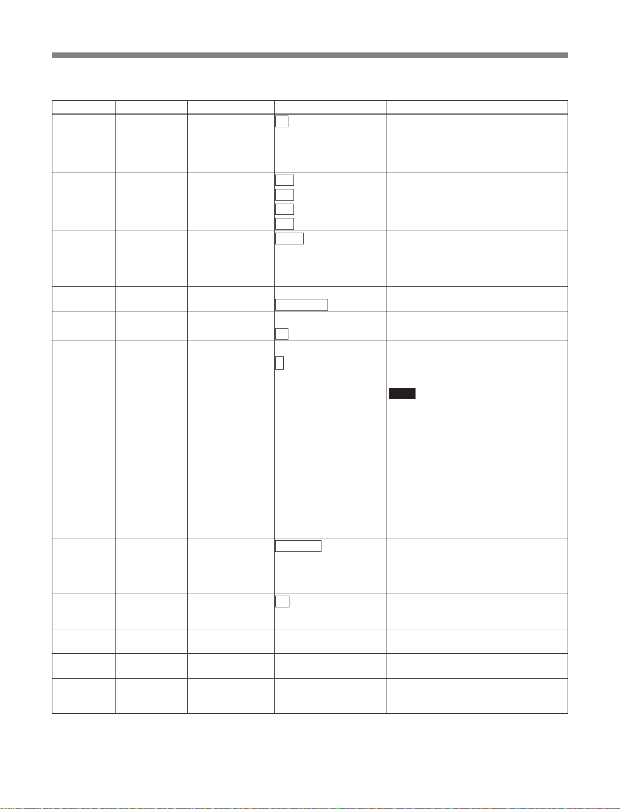
List of Menus
•In sdti-cp_to_asi mode
Item number Category Item Arguments Function
E001** link_mng (Tx) rtp_tx off Invalidates MPEG streaming output
through the MSBA-20IP.
on Validate MPEG streaming output through
E002** link_mng (Tx) rtp_tx_ip 000 to 255. Sets the destination IP address for MPEG
000 to 255.
000 to 255.
000 to 255
E003** link_mng (Tx) rtp_tx_port 50000 to 65534 Sets the UDP port No. for MPEG
E004** link_mng (Tx) rtp_tx_ssrc 0x00000000 to Sets “SSRC” which is member of RTCP.
0x01234567 to 0xffffffff Default value is 0x01234567.
E005** link_mng (Tx) rtp_tx_fec_mode off Invalidates Error collection.
on Validate Error collection.
E006** link_mng (Tx) rtp_tx_format 1 Selects Streaming packet format.
2 1: 1 TS packet per IPdatagram
E007** link_mng (Tx) rtp_tx_cname MSB-2000 Sets “CNAME” which is member of RTCP.
E031** link_mng (Tx/Rx) tos_field 00 to ff Specifies the value (8 bits) of the Tos field
E998** link_mng cancel – Cancels a link_mng change before
E999** link_mng init – Returns link_mng items to their factory
–** link_mng list – Displays the list set in link_mng.
the MSBA-20IP. Streaming supports up to
35 Mbps as a TS rate.
streaming output through the MSBA-20IP
For Multicast transmission, select in the
range 224.0.0.0 to 239.255.255.255.
streaming output through the MSBA-20IP.
The port No. can only be set to an even
number. The RTCP port No. is the setting
value plus one.
2: 6 TS packets per IP datagram
Note
It is recommended to use a setting of “2”
with less overhead. Avoid using both “1”
and “2” on the same network.
The IP transfer bandwidth required for
each TS rate is as follows.
• For a setting of “1” when “C165” is “off”:
141% of TS rate
• For a setting of “1” when “C165” is “on”:
156% of TS rate
• For a setting of “2” when “C165” is “off”:
107% of TS rate
• For a setting of “2” when “C165” is “on”:
122% of TS rate
Default CNAME here is “MSB-2000”.
Maximum length is 15 characters.The
characters that can be used are ASCII
codes in the range 0x21 to 0x7d.
(Diff serve field) of IP packets output by the
MSBA-20IP.
execution.
default settings.
This is a special-purpose command for
RS232C/telnet operation.
.
70
Page 71
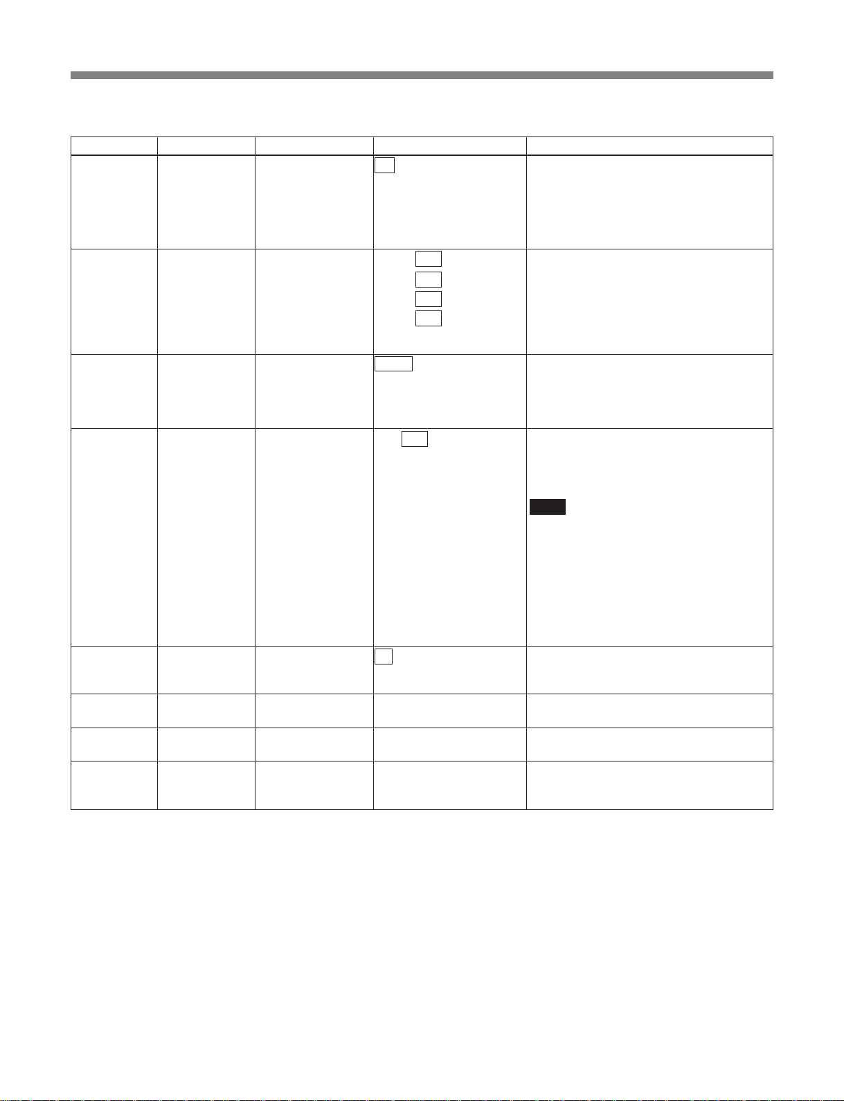
List of Menus
•In asi_to_sdti-cp mode
Item number Category Item Arguments Function
E021** link_mng (Rx) rtp_rx off Invalidates MPEG streaming input through
the MSBA-20IP.
on Validates MPEG streaming input through
E022** link_mng (Rx) rtp_rx_ip 000 to 255 . Sets the source IP address for MPEG
000 to 255 .
000 to 255 .
000 to 255
E023** link_mng (Rx) rtp_rx_port 50000 to 65534 Sets the UDP port No. which should be
E024** link_mng (Rx) buffer_depth 0 to 100 to 2000 Specifies the MSBA-20IP receiving buffer
E031** link_mng (Tx/Rx) tos_field 00 to ff Specifies the value (8 bits) of the Tos field
E998** link_mng cancel – Cancels a link_mng change before
E999** link_mng init – Returns link_mng items to their factory
–** link_mng list – Displays the list set in link_mng.
the MSBA-20IP instead of ASI input
Streaming supports up to 35 Mbps as a TS
rate.
stream input through MSBA-20IP.
If set to 255.255.255.255 data will be
received regardless of the MPEG stream
input source IP address. However, to
receive multicasts, set in the range4.0.0.0
to 239.255.255.255.
obtained as an MPEG streaming data
through the MSBA-20IP. The port No. can
only be set to an even number. The RTCP
port No. is the setting value plus one.
depth.
The range of settings is from 0 to 2000 ms
(in 1 ms increments).
Note
Normally use the default setting of “100.”
The receiving buffer depth range ensuring
a correct operation depends on the setting
in “C061:ts_rate”, “C165:rtp_tx_fec_mode”
and “C166:rtp_tx_format” on the
transmitting side, so care is required when
changing the settings.
For details, refer to the Maintenance
Manual.
(Diff serve field) of IP packets output by the
MSBA-20IP.
execution.
default settings.
This is a special-purpose command for
RS232C/telnet operation.
71
Page 72
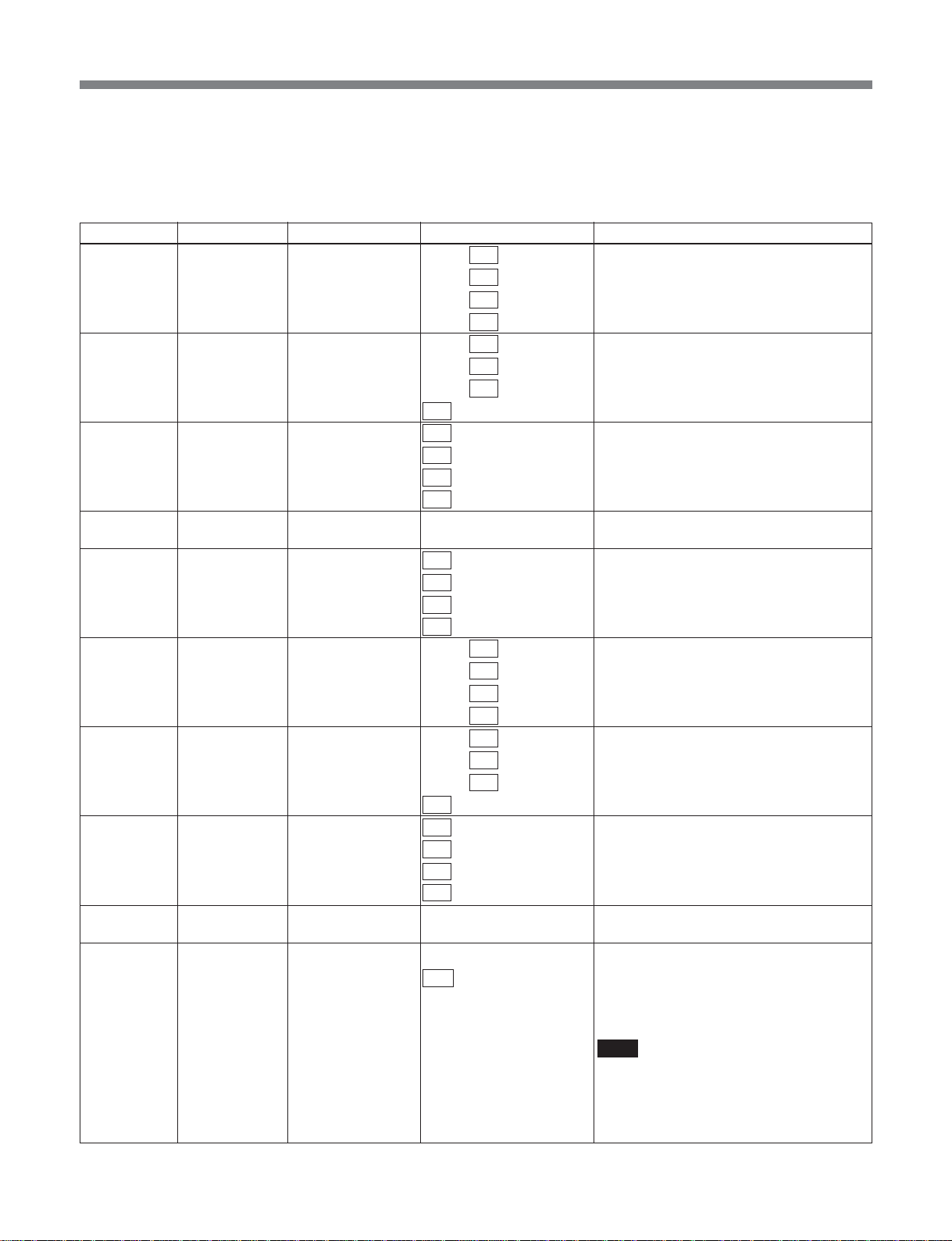
List of Menus
L:network menu
This menu is used to make settings for the Ethernet
interface of the MSB-2000 and the Ethernet option
board (MSBA-20IP).
Item number Category Item Arguments Function
L001 network ip_addr 000 to 192 to 255. Specifies the IP address of the MSB-2000.
000 to 168 to 255.
000 to 001 to 255.
000 to 002 to 255
L002 network netmask 000 to 255 . Specifies the net mask of the MSB-2000.
000 to 255 .
000 to 255 .
000 to 255
L003 network gateway 000 to 255. Specifies the default gate way of the
000 to 255.
000 to 255.
000 to 255
L004 network mac_addr – Display the machine address of the MSB-
L005 network ping 000 to 255. Specifies the destination IP address for
000 to 255.
000 to 255.
000 to 255
L011** network opt_ip_addr 000 to 192 to 255.
000 to 168 to 255.
000 to 002 to 255.
000 to 002 to 255
L012** network opt_netmask 000 to 255 . Specifies the net mask of the
000 to 255 .
000 to 255 .
000 to 255
L013** network opt_gateway 000 to 255. Specifies the default gateway for the
000 to 255.
000 to 255.
000 to 255
L014** network opt_mac_addr – Displays the machine address of the
L015** network phy_mode 100 This is a 100 Mbps full-duplex fixed mode.
auto This enables auto negotiation. As a result
MSB-2000.
2000.
ping.
Specifies the IP address of the MSBA-20IP.
MSBA-20IP.
MSBA-20IP.
MSBA-20IP.
of negotiation with the other end, the
connection is made at the highest speed
mode.
Note
Be sure to check the device connected at
the other end, and set to the same
communications mode. If not set to the
same communications mode, normal
operation may not be possible.
72
Page 73
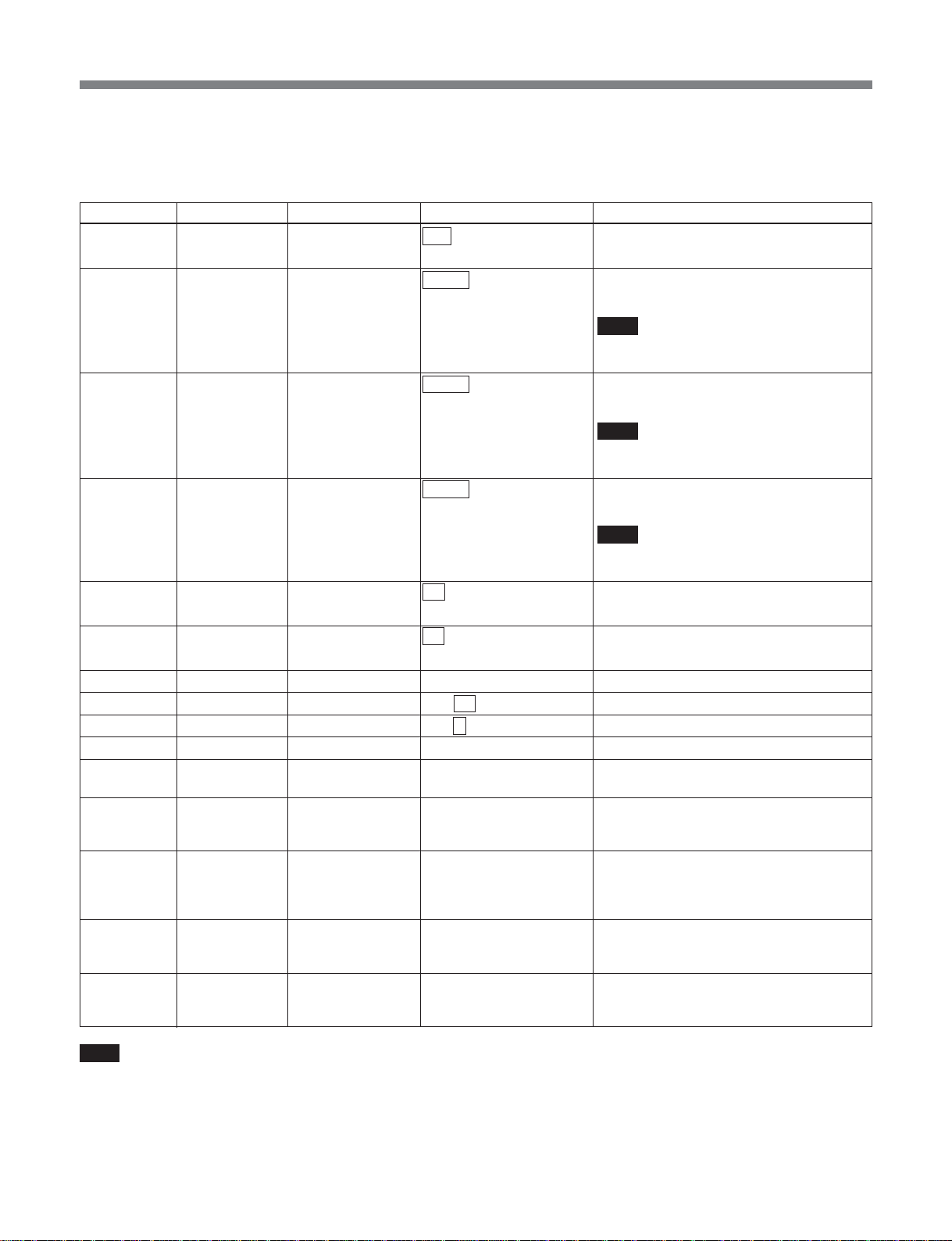
List of Menus
M:setup-msb menu
This menu contains common settings for the MSB-
2000.
Item number Category Item Arguments Function
M001 setup-msb video_system 525 Selects video system 525.
625*** Selects video system 625.
M002 setup-msb lock-web unlock Accepts control from from the web.
lock Inhibits control from the web.
Note
Even when control is disabled, this can be
unlocked through the web.
M003 setup-msb lock-telnet unlock Accepts control from telnet.
lock Inhibits control from telnet.
Note
Even when control is disabled, this can be
unlocked through telnet.
M004 setup-msb lock-snmp unlock Accepts control from snmp.
lock Inhibits control from snmp.
Note
Even when control is disabled, this can be
unlocked through snmp.
M008 setup-msb remote1 off Disables VTR remote 1.
VTR Enables VTR remote 1.
M009 setup-msb remote2 off Disables VTR remote 2.
VTR Enables VTR remote 2.
M010 setup-msb date [yymmdd]hhmm Sets the date and time.
M011 setup-msb lcd_cont 1 to 12 to 20 (not on help) Sets the LCD contrast.
M012 setup-msb lcd_bright 1 to 9 to 20 (not on help) Sets the LCD brightness.
M013 setup-msb serial_no –
M014** setup-msb opt_serial_no – Displays the serial number of the MSBA-
– setup-msb parameter_list – Displays all the currently set parameters.
– setup-msb parameter_file – Creates a parameter file named
– setup-msb parameter_load – Loads a parameter file named “PARAMS.”
– setup-msb list – Displays the list set for setup-msb.
Displays the serial number of the MSB-2000.
20IP.
This is a special-purpose command for
RS232C/telnet operation.
“PARAMS.”
This is a special-purpose command for
RS232C/telnet operation.
This is a special-purpose command for
RS232C/telnet operation.
This is a special-purpose command for
RS232C/telnet operation.
Note
The parameter file holds the values of all settings
in the B, C, E, L, M, N, S, and U menus and
SNMP menu.
For details of the parameter file, refer to the
Maintenance Manual.
73
Page 74
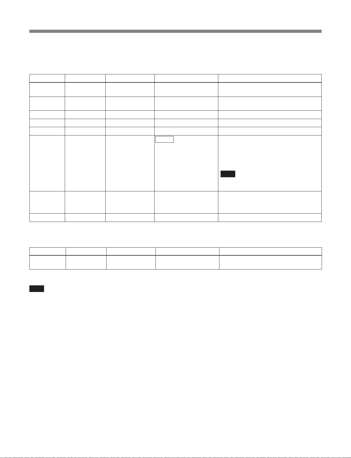
List of Menus
N:maintenance menu
This menu provides special commands for
maintenance. It is not normally used.
Item number Category Item Arguments Function
N001 maintenance version – Displays the version number of the MSB-
2000.
N002 maintenance opt_version – Displays the version number of the MSBA-
20IP.
N011 maintenance lcd_test – Tests front panel LCD.
N012 maintenance lamp_test – Tests front panel indicators.
N013 maintenance sw_test – Tests front panel switches.
N014 maintenance video_rate normal “C013:setup video_rate” can be set in the
normal range.
extended If “C012:setup video_encmode” is other
than “IMX,” the minimum limit for
“C013:setup video_rate” is 2 Mbps.
Note
Note that operation in “extended” mode
cannot be guaranteed at present.
N998 maintenance reset reset Stream process and below is reset;
Network is unaffected.
all Resets including network
N999 maintenance init – Returns settings to their factory defaults.
P:save menu
This menu saves user settings.
Item number Category Item Arguments Function
P save save 1 to 6 Up to six sets of user settings can be
saved.
Note
The user settings hold the values of all settings in the
B, C, E, L, M, N, S and U menus and SNMP menu.
You can check the contents of the user settings using a
parameter file.
For details of parameter files, refer to the Maintenance
Manual.
74
Page 75

List of Menus
R:recall menu
This menu recalls user settings.
Item number Category Item Arguments Function
R recall recall 1 to 6 Recalls the specified set of settings from
S:osd menu
This menu makes OSD-related settings.
Item number Category Item Arguments Function
S001 osd display off Invalidates OSD output to the SDI MON
on Validates OSD output to the SDI MON
S002 osd control push ENTER to For OSD operation, the arrow keys are
enter dedicated to the OSD for cursor
push MENU to This disconnects the arrow keys from the
enter OSD.
the six sets of user settings.
(SUPER) connector.
(SUPER) connector.
movement.
T:status menu
These commands are used to display information
obtained from the input signal.
Item number Category Item Arguments Function
– status all – Displays all information from T001 to T057.
T001 status ts_rate – Outputs the measured value of the TS bit
rate on the ASI IN connector in asi_to_sdi/
asi_to_sdti-cp/tx-rx/tx-rx (cm) mode.
In any other mode or when there is no
input TS stream, outputs “--------” signifying
that this is invalid.
T002 status pat_version – Outputs the TS stream PAT version during
selection/decoding in asi_to_sdi/
asi_to_sdti-cp/tx-rx/tx-rx (cm) mode.
In any other mode or when there is no
input TS stream, outputs “--------” signifying
that this is invalid.
If the value is not within the tolerance of
the MSB specification, “not accepted.” is
appended to the output.
Permitted values: 0≤num≤31
T003 status pat_interval – Outputs the TS stream PAT interval
(average value over TBD seconds) during
selection/decoding, in asi_to_sdi/
asi_to_sdti-cp/tx-rx/tx-rx (cm) mode.
In any other mode or when there is no
input TS stream, outputs “--------” signifying
that this is invalid.
If the value is not within the tolerance of
the MSB specification, “not accepted.” is
appended to the output.
Permitted values: 0≤num≤200
75
Page 76

List of Menus
Item number Category Item Arguments Function
T004 status pmt_version – Outputs the TS stream PMT version during
selection/decoding, in asi_to_sdi/
asi_to_sdti-cp/tx-rx/tx-rx (cm) mode.
In any other mode or when there is no
input TS stream, outputs “--------” signifying
that this is invalid.
If the value is not within the tolerance of
the MSB specification, “not accepted.” is
appended to the output.
Permitted values: 0≤num≤31
T005 status pmt_interval – Outputs the TS stream PMT interval
T006 status program_list – Outputs a list of program numbers written
T007 status rx_program_no – Outputs the selected program number in
T008 status program_map_pid – Outputs the PMT PID written in TS stream
(average value over TBD seconds) during
selection/decoding in asi_to_sdi/
asi_to_sdti-cp/tx-rx/tx-rx (cm) mode.
In any other mode or when there is no
input TS stream, outputs “--------” signifying
that this is invalid.
If the value is not within the tolerance of
the MSB specification, “not accepted.” is
appended to the output.
Permitted values: 0≤num≤200
in TS stream PAT in asi_to_sdi/asi_to_sdticp/tx-rx/tx-rx (cm) mode.
In any other mode or when there is no
input TS stream, outputs “--------” signifying
that this is invalid.
If the value is not within the tolerance of
the MSB specification, “not accepted.” is
appended to the output.
Permitted values: 1≤num≤65535
A list of program numbers for a maximum
of 12 programs is output.
asi_to_sdi/asi_to_sdti-cp/tx-rx/tx-rx (cm)
mode.
In any other mode or when there is no
input TS stream, outputs “--------” signifying
that this is invalid.
If the value is not within the tolerance of
the MSB specification, “not accepted.” is
appended to the output.
Permitted values: 1≤num≤65535
PAT in asi_to_sdi/asi_to_sdti-cp/tx-rx/tx-rx
(cm) mode.
In any other mode or when there is no
input TS stream, outputs “--------” signifying
that this is invalid.
If the value is not within the tolerance of
the MSB specification, “not accepted.” is
appended to the output.
Permitted values: 0x10≤num≤0x1ffe
76
Page 77

List of Menus
Item number Category Item Arguments Function
T009 status network_pid – Outputs the NIT PID written in the TS
stream PAT in asi_to_sdi/asi_to_sdti-cp/txrx/tx-rx (cm) mode.
In any other mode or when there is no
input TS stream, outputs “--------” signifying
that this is invalid.
If the value is not within the tolerance of
the MSB specification, “not accepted.” is
appended to the output.
Permitted values: 0x10≤num≤0x1ffe
T010 status pcr_pid – In asi_to_sdi/asi_to_sdti-cp/tx-rx/tx-rx (cm)
T011 status pcr_interval – Outputs the TS stream PCR interval during
T012 status video_pid – Outputs the TS stream video PID during
T013 status mpeg_ch12_pid – Outputs the PID of the first MPEG audio
T014 status mpeg_ch34_pid – In the same way as above, displays the
mode, outputs the PCR PID written in the
TS stream PAT.
In any other mode or when there is no
input TS stream, outputs “--------” signifying
that this is invalid.
If the value is not within the tolerance of
the MSB specification, “not accepted.” is
appended to the output.
Permitted values: 0x10≤num≤0x1ffe
selection/decoding in asi_to_sdi/
asi_to_sdti-cp/tx-rx/tx-rx (cm) mode.
In any other mode or when there is no
input TS stream, outputs “--------” signifying
that this is invalid.
If the value is not within the tolerance of
the MSB specification, “not accepted.” is
appended to the output.
Permitted values: 0≤num≤200
selection/decoding in asi_to_sdi/
asi_to_sdti-cp/tx-rx/tx-rx (cm) mode.
In any other mode or when there is no
input TS stream, outputs “--------” signifying
that this is invalid.
If the value is not within the tolerance of
the MSB specification, “not accepted.” is
appended to the output.
Permitted values: 0x10≤num≤0x1ffe
stream in the PAT from the TS stream
audio stream during selection/decoding in
asi_to_sdi/asi_to_sdti-cp/tx-rx/tx-rx (cm)
mode.
In any other mode or when there is no
input TS stream, outputs “--------” signifying
that this is invalid.
If the value is not within the tolerance of
the MSB specification, “not accepted.” is
appended to the output.
Permitted values: 0x10≤num≤0x1ffe
PID for MPEG audio channels 3 and 4
currently being decoded.
77
Page 78

List of Menus
Item number Category Item Arguments Function
T015 status lpcm_pid – Outputs the PID of the first LPCM audio
stream in the PAT from the TS stream
audio stream during selection/decoding in
asi_to_sdi/asi_to_sdti-cp/tx-rx/tx-rx (cm)
mode.
In any other mode or when there is no
input TS stream, outputs “--------” signifying
that this is invalid.
If the value is not within the tolerance of
the MSB specification, “not accepted.” is
appended to the output.
Permitted values: 0x10≤num≤0x1ffe
T016 status lpcm_channel – In asi_to_sdi/asi_to_sdti-cp/tx-rx/tx-rx (cm)
mode, when an LPCM audio stream is
being selected/decoded, shows the
lpcm_channel being decoded.
Depending on the input, “1-2”, “3-4”, “1-4”,
or “1-8” is output.
In cases other than this, outputs “--------”
signifying that this is invalid.
T017 status lpcm_word_len – In asi_to_sdi/asi_to_sdti-cp/tx-rx/tx-rx (cm)
mode, when an LPCM audio stream is
being selected/decoded, shows the word
length of the lpcm audio stream being
decoded.
Depending on the input, “16”, “20”, or “24”
is output.
In cases other than this, outputs “--------”
signifying that this is invalid.
T018 status lpcm_avail_ch – In asi_to_sdi/asi_to_sdti-cp/tx-rx/tx-rx (cm)
T019 status mpeg_ch12_mode – In asi_to_sdi/asi_to_sdti-cp/tx-rx/tx-rx (cm)
T020 status mpeg_ch12_rate – In asi_to_sdi/asi_to_sdti-cp/tx-rx/tx-rx (cm)
T021 status mpeg_ch34_mode – Similar to T019, outputs the mpeg_ch34
T022 status mpeg_ch34_rate – Similar to T020, outputs the mpeg_ch34
mode, when an LPCM audio stream is
being selected/decoded, shows in bitmap
fashion which channels of LPCM are
present or absent.
If channels 1/2: “12------”
If channels 3/4: “--34----”
If channels 1-4: “1234----”
In cases other than this, outputs “--------”
signifying that this is invalid.
mode, when decoding an MPEG audio
stream corresponding to MPEG_ch12,
outputs the mode of the stream.
The output value is “single” “dual” “stereo”,
or “joint stereo”.
In cases other than this, outputs “--------”
signifying that this is invalid.
mode, when decoding an MPEG audio
stream corresponding to MPEG_ch12,
outputs the bit rate of the stream. (The last
status is latched, and output.)
The output value is “96kbps” “112kbps”
“128 kbps” “160kbps” “192kbps” “224kbps”
“256 kbps” “320kbps” or “384kbps”.
In cases other than this, outputs “--------”
signifying that this is invalid.
mode.
bitrate.
78
Page 79

List of Menus
Item number Category Item Arguments Function
T023 status profile_level – Outputs the TS stream video ES profile
and level during selection/decoding in
asi_to_sdi/asi_to_sdti-cp/tx-rx/tx-rx (cm)
mode.
The output value is “MP@ML” “MP@HL”
“4:2:2P@ML” or “4:2:2P@HL”.
In cases other than this, outputs “--------”.
T024 status video_encmode – Outputs the TS stream video ES encode
T025 status video_rate – Outputs the measured value of the TS
T026 status vitc – In asi_to_sdi/asi_to_sdti-cp/tx-rx/tx-rx (cm)
T027 status rx_c_caption – In asi_to_sdi/asi_to_sdti-cp/tx-rx/tx-rx (cm)
T028 status history – In asi_to_sdi/asi_to_sdti-cp/tx-rx/tx-rx (cm)
T029 status umid – In asi_to_sdi/asi_to_sdti-cp/tx-rx/tx-rx (cm)
T030 status pri_data – In asi_to_sdi/asi_to_sdti-cp/tx-rx/tx-rx (cm)
mode during selection/decoding in
asi_to_sdi/asi_to_sdti-cp/tx-rx/tx-rx (cm)
mode.
The output value is “LD All P” “LD ALL I”
“LD IPPP” or “LONG”.
In cases other than this, outputs “--------”.
stream video ES rate during selection
decoding in asi_to_sdi/asi_to_sdti-cp/tx-rx/
tx-rx (cm) mode.
If the value is not within the tolerance of
the MSB specification, “not accepted.” is
appended to the output.
In cases other than this, outputs “--------”.
Permitted values: 0≤num≤51
mode, during selection/decoding of a TS
stream, outputs whether or not a private
stream is included on which VITC can be
placed.
When the input is present: “present”
When no input is present: “absent”
In cases other than this, outputs “--------”.
mode, indicates whether closed captions
are present.
When the input is present: “present”
When no input is present: “absent”
In cases other than this, outputs “--------”.
mode, indicates whether history is present.
When the input is present: “present”
When no input is present: “absent”
In cases other than this, outputs “--------”.
mode, during selection/decoding of a TS
stream, outputs whether or not a private
stream is included on which UMID can be
placed.
When the input is present: “present”
When no input is present: “absent”
In cases other than this, outputs “--------”.
mode, during a selection/decoding of a TS
stream, outputs a private stream list.
In any other mode or when there is no
input TS stream, outputs “--------” signifying
that this is invalid.
If the value is not within the tolerance of
the MSB specification, “not accepted.” is
appended to the output.
Permitted values: 0x10≤num≤0x1ffe
A maximum of three private stream ids are
output.
79
Page 80

List of Menus
Item number Category Item Arguments Function
T031 status pict_size – In asi_to_sdi/asi_to_sdti-cp/tx-rx/tx-rx (cm)
mode, during selection/decoding of a TS
stream, outputs the video ES pict_size
(image frame).
The output value is “720×480” “544×480”
“480×480” “352×480” “352×240” “720×512”
“720×608” “720×576” “544×576” “480×576”
“352×576” “352×288” or “Other”.
In cases other than this, outputs “--------”.
T032 status ref – In all modes, indicates whether there is an
input on the ref connector.
When present: “present”
When absent: “absent”
T033 status sdi_sdti – In tx-rx/tx-rx (cm) sdi_to_asi mode,
indicates whether there are SDI signals on
the sdi/sdti-cp connector.
When the input is present: “present”
When no input is present: “absent”
In sdti-cp_to_asi mode, indicates whether
there are SDTI-CP signals on the sdi/sdti
connector.
When the input is present: “present”
When no input is present: “absent”
In asi_to_sdi/asi_to_sdti-cp mode, outputs
“--------” signifying that this is invalid.
T034 status asi – In tx-rx/tx-rx (cm) asi_to_sdi/asi_to_sdti-cp
mode, indicates whether or not there is an
input on the ASI connector.
When present: “present”
When absent: “absent”
In asi_to_sdi/asi_to_sdti-cp mode, outputs
“--------” signifying that this is invalid.
T035 status cascade_asi – In the case of mux on, whether or not there
T041 status link_status – In all modes, displays the connection
T042 status link_speed – In all modes, when link_status is “up,” the
is an input on the Cascade ASI input
connector.
When present: “present”
When absent: “absent”
When mux off, outputs “--------” signifying
that this is invalid.
status of the MSBA-20IP 100BASE-TX
connector.
If connected: “up”
If not connected: “down”
Note that when the MSBA-20IP board is
not installed, “RTP option is not mounted”
is output.
communications speed is displayed, shown
as:
For a 10 Mbps connection: “10”
For a 100 Mbps connection: “100”
If link_status is “down,” “--------” is output.
Note that when the MSBA-20IP board is
not installed, “RTP option is not mounted”
is output.
80
Page 81

List of Menus
Item number Category Item Arguments Function
T043 status link_duplex – In all modes, when link_status is “up” this
shows the communications mode, as
follows:
When link_status is “up” and there is a fullduplex connection: “full-duplex”
For a half-duplex connection: “half-duplex”
If link_status is “down,” “--------” is output.
Note that when the MSBA-20IP board is
not installed, “RTP option is not mounted”
is output.
T044 status ether_rx_packet – In all modes, the number of Ethernet
T045 status ether_rx_error – In all modes, out of the Ethernet packets
T046 status rtp_rx_port_no – In asi_to_sdi/asi_to_sdti-cp/tx-rx/tx-rx (cm)
T047 status rtp_rx_packet – In asi_to_sdi/asi_to_sdti-cp/tx-rx/tx-rx (cm)
packets received by the MSBA-20IP in the
most recent one-second interval is shown.
The maximum output value is “65535.”
That is to say, if 65535 or more packets
are received in a second, the output is
“65535.”
Note that when the MSBA-20IP board is
not installed, “RTP option is not mounted”
is output.
received by the MSBA-20IP in the most
recent one-second interval, the number of
packets in which an FEC error was
detected is shown.
The maximum output value is “255.” That
is to say, if there were 255 or more error
packets in a second, the output is “255.”
Note that when the MSBA-20IP board is
not installed, “RTP option is not mounted”
is output.
mode, the port No. of the rtp packets
currently being received (udp port) is
output.
In sdi_to_asi/sdti-cp_to_asi mode, outputs
“--------” to indicate that this is invalid.
Permitted values:
50000≤rx_port_no≤65534, and
rx_port_no=0
For rx_port_no=0, to indicate that no rtp
packets are received, “--------” is output.
Note that when the MSBA-20IP board is
not installed, “RTP option is not mounted”
is output.
mode, outputs the number of RTP packets
received from the network in the most
recent one-second interval.
In sdi_to_asi/sdti-cp_to_asi mode, outputs
“--------” to indicate that this is invalid.
The maximum output value is “65535.”
That is to say, if 65535 or more RTP
packets are input in a second, the output is
“65535.”
Note that when the MSBA-20IP board is
not installed, “RTP option is not mounted”
is output.
81
Page 82

List of Menus
Item number Category Item Arguments Function
T048 status rtp_seq_error – In asi_to_sdi/asi_to_sdti-cp/tx-rx/tx-rx (cm)
mode, outputs the number of RTP
sequence discontinuities detected in the
most recent one-second interval.
In sdi_to_asi/sdti-cp_to_asi mode, outputs
“--------” to indicate that this is invalid.
The maximum output value is “255.” That
is to say, if there are 255 or more RTP
packet receiving errors are in a second, the
output is “255.”
Note that when the MSBA-20IP board is
not installed, “RTP option is not mounted”
is output.
T049 status rtp_rx_fec_mode – In asi_to_sdi/asi_to_sdti-cp/tx-rx/tx-rx (cm)
T050 status ts_corrected – In asi_to_sdi/asi_to_sdti-cp/tx-rx/tx-rx (cm)
T051 status ts_uncorrected – In asi_to_sdi/asi_to_sdti-cp/tx-rx/tx-rx (cm)
mode, indicates whether error correction is
enabled or disabled (fec_mode) for the
RTP packets currently being received.
In sdi_to_asi/sdti-cp_to_asi mode, outputs
“--------” to indicate that this is invalid.
If the stream has error correction, outputs
“on”, and if the stream has no error
correction, outputs “off.”
When no RTP packets are received, “-------
-” is output.
Note that when the MSBA-20IP board is
not installed, “RTP option is not mounted”
is output.
mode, when fec_mode is “on,” outputs the
number of TS packets in the most recent
one-second interval amended as a result of
applying FEC correction.
When fec_mode is “off,” or in asi_to_sdi/
asi_to_sdti-cp mode, outputs “--------” to
indicate that this is invalid.
The maximum output value is “255.” That
is to say, if FEC correction applies to 255
or more TS packets in a second, the output
is “255.”
Note that when the MSBA-20IP board is
not installed, “RTP option is not mounted”
is output.
mode, when fec_mode is “on,” outputs the
number of TS packets the most recent
one-second interval for which a correction
by FEC was not possible.
When fec_mode is “off,” or in sdi_to_asi/
sdti-cp_to_asi mode, outputs “--------” to
indicate that this is invalid.
The maximum output value is “255.” That
is to say, if 255 or more TS packets could
not be corrected in a second, the output is
“255.”
Note that when the MSBA-20IP board is
not installed, “RTP option is not mounted”
is output.
82
Page 83

List of Menus
Item number Category Item Arguments Function
T052 status rtp_rx_error – In asi_to_sdi/asi_to_sdti-cp/tx-rx/tx-rx (cm)
mode, when fec_mode is “on,” outputs the
total number of TS packets for which FEC
correction was not possible from the start
of receiving (when proc start is submitted)
until the command is submitted.
The maximum output value is “255.” That
is to say, when there are a total of 255 or
more TS packet for which FEC correction
was not possible, the output is “255.”
This status value only is reset to zero when
proc start is submitted.
Note that when the MSBA-20IP board is
not installed, “RTP option is not mounted”
is output.
T053 status rtp_rx_ssrc_no – In asi_to_sdi/asi_to_sdti-cp/tx-rx/tx-rx (cm)
mode, outputs the SSRC value of the
RTCP packet currently being received.
In sdi_to_asi/sdti-cp_to_asi mode, “--------”
is output.
If no RTCP packets are received, “--------”
is output.
Note that when the MSBA-20IP board is
not installed, “RTP option is not mounted”
is output.
T054 status rtcp_rx_cname – In asi_to_sdi/asi_to_sdti-cp/tx-rx/tx-rx (cm)
mode, outputs the CNAME field value of
the RTCP SDES packet currently being
received.
The output format is ASCII printable
characters (0x21≤x≤0x7d), with a
maximum of 15 characters, left aligned.
In sdi_to_asi/sdti-cp_to_asi mode, “--------”
is output.
If no RTCP packets are received, “--------”
is output.
Note that when the MSBA-20IP board is
not installed, “RTP option is not mounted”
is output.
T055 status rtp_tx – In sdi_to_asi/sdti-cp_to_asi/tx-rx/tx-rx (cm)
mode, outputs the RTP packet
transmission status.
In asi_to_sdi/asi_to_sdti-cp mode, outputs
“--------” to indicate that this is invalid.
If the rtp_tx command is “off,” “off” is
output.
If rtp_tx is “on,” but for any reason
transmission to the network is stopped,
“halt” is output.
If rtp_tx is “on,” and RTP packets are being
transmitted to the network, “running” is
output.
Note that when the MSBA-20IP board is
not installed, “RTP option is not mounted”
is output.
83
Page 84

List of Menus
Item number Category Item Arguments Function
T056 status rtp_tx_packet – In sdi_to_asi/sdti-cp_to_asi/tx-rx/tx-rx (cm)
mode, outputs the number of RTP packets
output to the network in the most recent
one-second interval.
In asi_to_sdi/asi_to_sdti-cp mode, outputs
“--------” to indicate that this is invalid.
The maximum output value is “65535.”
That is to say, if 65535 or more RTP
packets are output in a second, the output
is “65535.”
Note that when the MSBA-20IP board is
not installed, “RTP option is not mounted”
is output.
T057 status rtcp_tx_rr – In sdi_to_asi/sdti-cp_to_asi/tx-rx/tx-rx (cm)
mode, reports whether RTCP RR packets
are received for the RTP/RTCP packets
currently being transmitted, as follows:
If RR is being received: “alive”
If RR is not being received: “not alive”
In asi_to_sdi/asi_to_sdti-cp mode, outputs
“--------” to indicate that this is invalid.
Note that when the MSBA-20IP board is
not installed, “RTP option is not mounted”
is output.
84
Page 85
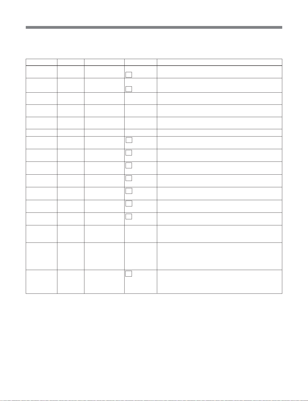
List of Menus
U:log menu
This menu makes log-related settings.
Item number Category Item Arguments Function
U001 log serial off Invalidates displaying logs on the serial on terminal.
U002 log telnet off Invalidates displaying logs on the telnet terminal.
U003 log dump_all – Makes a log file for 5000 logs. This log is updated cyclically.
U004 log dump_resume – Makes a log file for 1000 logs. This log is updated
U005 log dump_sub – Makes a log file for 1000 logs. This shows logs form
U006 log clear – Clears all logs.
– log filter_critical off Do not filter the Critical Error Log for telnet/serial output.
– log filter_major off Do not filter the Major Error Log for telnet/serial output.
– log filter_minor off Do not filter the Minor Error Log for telnet/serial output.
– log filter_warning off Do not filter the Warning Log for telnet/serial output.
– log filter_clear off Do not filter the Clear Error Log for telnet/serial output.
– log filter_command off Do not filter the Command Log for telnet/serial output.
– log filter_status off Do not filter the Status Log for telnet/serial output.
– log alarm_counts – For each of transmitting and receiving, output the number of
– log alarm_list critical Output the uncleared errors and warnings whose numbers
– log level_change off Do not change the log level.
on Validates displaying logs on the serial terminal.
on Validates displaying logs on the telnet terminal.
The File name is “logfile”. (Volatile)
cyclically. The File name is “logfile”. (Non volatile)
power on. The File name is “logfile”. (Volatile)
on Filter the Critical Error Log for telnet/serial output.
on Filter the Major Error Log for telnet/serial output.
on Filter the Minor Error Log for telnet/serial output.
on Filter the Warning Log for telnet/serial output.
on Filter the Clear Error Log for telnet/serial output.
on Filter the Command Log for telnet/serial output.
on Filter the Status Log for telnet/serial output.
errors and warnings that have not yet been cleared (as
three-digit decimal values).
major are shown by log alarm_counts, according to the
minor parameters, in device number order.
warning If the arguments are omitted, output all types in the
sequence critical, ... , warning.
on Change the log level.
code_load Record the codefile for changing the log level on this device.
code_list Output the codefile recorded on this device.
Supplementary information
The parameters of the “setup” class require the “proc
start” to be executed before they can be reflected in
real operation. Until the “proc start” is executed, the
return messages for them represent the values changed
with commands of the “setup” class.
•When there are parameters whose settings differ from
the values used in real operation, an “*” is postfixed
to the return message.
•When the value of a parameter being set or read
differs from its value used in real operation, an “**”
is postfixed to the return message.
85
Page 86

List of Menus
Notes
1.When video_system is changed, pict_size
correspondingly switches:
— between 525/“720x480” and 625/“720x576”, or
— between 525/“720x512” and 625/“720x608”.
2.When “setup-msb lock” is executed, the user interface
showing arguments can be used for “read only” with the
“setup-msb lock” being the only exception. The “proc
analyse” is also inhibited.
3.Unlike other commands, the “setup sync_phase” and
“setup lip_sync” commands in the setup menu become
effective without requiring the “proc start” to be executed.
4.In PID settings such as “video_pid”, “mpeg_ch12_pid”,
“mpeg_ch34_pid” and “lpcm-pid”, values 10 to 1f are
sometimes used as special id’s. Using values in the range
of 20 to 1ffe is therefore recommended. Similarly, for
“pri_pid_base”, the range of 20 to 1ff7 is recommended.
5.The log menu items filter_critical, filter_major,
filter_minor, filter_warning, filter_clear, filter_command,
filter_status, alarm_counts, alarm_list, and level_change
can only be controlled by Telnet/RS-232C.
For details of the log, refer to the Maintenance Manual
(supplied separately).
6.For details of the codefile format, refer to the
Maintenance Manual (supplied separately).
Example return messages
•proc
“”(NULL)
•proc start
“OK” or Command list if NG
•proc analyse
“OK” or Command list if NG
•setup init
“Initialized”
•setup cancel
“canceled”
•setup-msb mac_addr
##:##:##:##:##:##
•setup-msb ping
“{IP address} is alive” or “no answer from {IP
address}”
•setup-msb date
mm dd HH:MM:SS yyyy
yymmddHHMMSS (for front panel)
•setup-msb serial_no
#####
•maintenance version
Version and serial number of the unit
•maintenance reset
“OK”
•maintenance init
“Initialized”
Example error messages
Generally when a type error or the like is detected, the
error message “command not found” is returned.
•General commands of “setup” and “setup-msb”
classes;
“ERROR. Please do “init””: Resume data is
erroneous.
“ERROR”: Resume data is erroneous. (message for
the front panel)
“invalid parameter”: Un-covered argument
“out of range min=###” or “out of range max=###”:
Argument value is smaller than allowable.
“out of range”: Argument value is smaller than
allowable. (message for the front panel)
•maintenance reset, mode
“system is not ready”: The system under the network
host is not ready or has some troubles.
“not ready”: The system under the network host is not
ready or has some troubles. (message for the front
panel)
Consistency of setting values.
When “proc start” is executed, setting consistency is
checked and then the setup values are reflected in
operation.
When “proc analyse” is executed, setting consistence
is checked without having the setup values stored to
memory.
For the consistency check, the following requirements
are checked in the numbered order.
1. chroma vs. encmode
The consistency between 4:2:0 and IMX.
• “video_encmode IMX is not allowed for 4:2:0”
• “video_encmode NG” (message for the front
panel)
2. encmode vs. video_rate (4:2:2 only)
Video bit rate consistency
IMX allows 30Mbps as the lowest bit rate.
• “video_rate lower limit is 30Mbps”
• “video_rate≥30” (message for the front panel)
For other than the IMX, the highest video bit rate is
30Mbps.
• “video_rate upper limit is 30Mbps”
• “video_rate≤30” (message for front panel)
86
Page 87

List of Menus
3. chroma vs. video_rate
In case of 4:2:0, the highest video bit rate is 15Mbps
and the lowest is 4Mbps.
• “video_rate upper limit is 15Mbps”
• “video_rate≤15” (message for the front panel)
• “video_rate lower limit is 4Mbps”
• “video_rate≥4” (message for the front panel)
In case of 4:2:2 other than for the IMX, the lowest
video bit rate is 6Mbps.
• “video_rate lower limit is 6Mbps”
• “video_rate≥6” (message for front panel)
4. video_rate vs. ts_rate
(1) If video_rate = “auto”, ts_rate = “auto” and
rtp_tx = “off” or “RTP option is not mounted”,
the video bit rate constitutes the highest bit rate
for the mode.
4:2:0: video_rate = 15Mbps
4:2:2 not IMX: video_rate = 30Mbps
4:2:2 IMX: video_rate = 50Mbps
and then the ts_rate is calculated. If the
calculated ts_rate is larger than allowable, the
following message appears.
“too large data for TS”
“too large stream” (for the front panel)
(2) When video_rate = “auto”, ts_rate = “auto”, and
rtp_tx = “on”
Setting ts_rate to the maximum value (35 Mbps)
when an MSBA-20IP is installed, the video_rate
is back-calculated.
If the calculated video_rate is larger than the
maximum allowable value for the mode, the
maximum value for the mode is made the
video_rate.
4:2:0: video_rate = 15Mbps
4:2:2 not IMX: video_rate = 30Mbps
4:2:2 IMX: video_rate = 50Mbps
If the calculated video_rate is smaller than the
following minimum allowable value for the
mode, it constitutes an error.
4:2:0: video_rate = 4Mbps
4:2:2 not IMX: video_rate = 6Mbps
4:2:2 IMX: video_rate = 30Mbps
The message “no room for video” is returned.
(3) If video_rate ≠ “auto” and ts_rate = “auto”, the
ts_rate is calculated automatically with the
video_rate used as reference.
If an overflow occurs, the following message is
returned:
“too large data for TS”
“too large stream” (message for the front
panel)
(4) If video_rate = “auto” and ts_rate ≠“auto”, the
video_rate is calculated automatically with the
ts_rate used as the reference.
If the calculated video_rate is larger than the
maximum allowable value for the mode, the
maximum value for the mode is made the
video_rate.
4:2:0: video_rate = 15Mbps
4:2:2 not IMX: video_rate = 30Mbps
4:2:2 IMX: video_rate = 50Mbps
If the calculated video_rate is smaller than the
following minimum allowable value for the
mode, it constitutes an error.
4:2:0: video_rate = 4Mbps
4:2:2 not IMX: video_rate = 6Mbps
4:2:2 IMX: video_rate = 30Mbps
The message “no room for video” is returned.
(5) If video_rate ≠ “auto” and ts_rate ≠ “auto”, the
ts_rate is calculated automatically with the
video_rate used as reference.
If the calculated value of ts_rate is larger than
the ts_rate, it constitutes an error.
“too large data for TS”
“too large stream”: (message for the front
panel)
5. Duplicate registration of PID
Whether audio_encmode and private_stream are on
or off, duplicate registration is not allowed except
for a combination of video and pcr. The PIDs are
checked in the following order:
video_pid
mpeg_ch12_pid
mpeg_ch34_pid
lpcm_pid
pcr_pid
program_map_pid
network_pid
pri_pid_base(+7)
If any duplicate registration of PID is detected, it
constitutes an error.
“video_pid & lpcm_pid are duplicated”
“PID video=lpcm” (message for the front panel)
“mpeg_ch12_pid & pri_pid are duplicated”
“PID mp12=private” (message for the front
panel)
87
Page 88

List of Menus
6. pict_size
4:2:0 allows only 720x480/720x576.
IMX allows only 720x512/720x608.
4:2:2 except for IMX allows both sizes.
If an error is detected, the message “pict_size NG”
is returned.
7. audio_encmode
IMX allows only LPCM as audio encoding mode. If
mpeg audio is detected in this mode, it constitutes
an error.
“MPEG audio is not allowed for IMX video”
“audio_encmode NG” (message for the front
panel)
8. rtp
When rtp_tx is set to “on”, the upper limit for
ts_rate is 35 Mbps.
“ts_rate≤35 (RTP)”
When rtp_tx/rtp_rx is set to “on”, if any of
tx_udata1/tx_udata2/
rx_udata1/rx_udata2 is also “on”, this generates a
check fail.
“RTP and UserData are alternative”
“set rtpudata” (for front panel)
9. closed caption
If tx_c_caption is “on” and video_encmode is
“IMX”, this generates a check fail.
“no_tx_c_caption with IMX video”
“tx_c_caption/IMX” (for front panel)
All these nine items are checked, and a number of lines
of text is given as return message to show the check
results.
Message examples
•for the front panel
“C011,C012 video_encmode NG
C011,C013 video_rate≤15”
•for others (Serial/ Telnet/ Http)
“C011 video_encmode IMX is not allowed for 4:2:0
C012 video_encmode IMX is not allowed for 4:2:0
C011 video_rate upper limit is 15Mbps
C013 video_rate upper limit is 15Mbps”
88
Page 89

Simple Network Management Protocol (SNMP)
Simple Network Management Protocol (SNMP)
This unit supports the following groups of SNMP V1
MIB2:
•System Gp.
1)
•Interface Gp.
•IP Gp.
•ICMP Gp.
•TCP Gp.
2)
•UDP Gp.
•SNMP Gp.
3)
For information about the SNMP commands supported
by this unit, Private Management Information Base
(MIB), and SNMP traps, see the pages indicated
below.
•SNMP commands
Organization of commands (page 90)
Details of commands (page 90)
•Private MIB
Organization of system information (page 93)
Details of system information (page 93)
Organization of commands (page 94)
Details of commands (page 96)
Organization of status information (page 100)
Details of status information (page 102)
Organization of msb traps (page 107)
Details of msb traps (page 108)
•SNMP Traps (page 110)
Notes
•For some MIBs, there is no support.
1) The sysORTable and sysORLastChange are not
supported.
2) The tcpConnTable is not supported.
3) snmpSilentDrops and snmpProxyDrops are not
supported.
•When the SNMP Trap setting is “Enable”, consider
around 118 kbps as the upper limit on UDP packet
traffic to the Network Node Manager.
•Use SNMP in a network environment protected by a
firewall or other security measures.
•Carry out the loading of Private MIB definition files
to the Network Node Manager in the sequence sonysmi.mib, sony-common.mib, and sony-msb2000.mib.
Similarly, unload in the order: sony-msb2000.mib,
sony-common.mib, sony-smi.mib.
89
Page 90

Simple Network Management Protocol (SNMP)
y
[
]
SNMP Commands
The organization and details of the SNMP commands
are as follows.
Organization of SNMP commands
snmp init
sys
comm
host
trap
list
name
contact
location
list
add
clear
list
add
clear
list
switch
select
<name>
<name>
<name>
<name>
<name>
<name>
<name>
[enable_all/enable_select/disable_all]
warning
clear_warning
minor
clear_minor
major
clear_major
critical
command
status
summar
[ro/wo/rw]
<community>
<community>
[enable/disable]
[enable/disable]
[enable/disable]
[enable/disable]
[enable/disable]
[enable/disable]
[enable/disable]
[enable/disable]
[enable/disable]
enable/disable
[enable_trap/disable_trap]
ip_addr
ip_addr
Details of SNMP commands
(1) snmp init:
Initializes the values of the SNMP commands
resumed in nonvolatile RAM.
This command is required when the unit is powered
on for the first time after installation or software
upgrading.
The initial command values are as follows:
•snmp sys name “” (NULL)
•snmp sys contact “” (NULL)
•snmp sys location “” (NULL)
•snmp comm “public” rw enable_trap
•snmp host “” (NULL)
•snmp trap switch disable_all
•snmp trap select clear disable
•snmp trap select warning disable
•snmp trap select minor disable
•snmp trap select major disable
•snmp trap select critical disable
•snmp trap select command disable
•snmp trap select status disable
After making command settings, it is necessary to
power off and on again.
(2) snmp sys list
Shows the settings of SNMP sysName, sysContact,
and sysLocation.
(3) snmp sys name <name>
Sets SNMP sysName. The maximum length is 24
characters.
This command is resumed.
(4) snmp sys contact <name>
Sets SNMP sysContact. The maximum length is 24
characters.
This command is resumed.
90
Page 91

Simple Network Management Protocol (SNMP)
(5) snmp sys location <name>
Sets SNMP sysLocation. The maximum length is
24 characters.
This command is resumed.
(6) snmp comm list
Displays the SNMP community name.
(7) snmp comm add <name> [ro/wo/rw]
[enable_trap/disable_trap]
Adds an SNMP community name. The maximum
length is 24 characters.
ro/wo/rw means Read-Only/Write-Only/ReadWrite.
Traps are controlled by enable_trap/disable_trap.
SNMP community name allows up to 5 names.
This command is resumed.
(8) snmp comm clear <name>
Clears the SNMP community name.
This command is resumed.
(9)snmp host list
Displays the SNMP host (manager).
(10)snmp host add <name> <community> ip_addr
Relates the SNMP host name to a community and
sets its IP address.
The maximum length is 24 characters.
The SNMP host allows up to 5 hosts.
This command is resumed.
(11)snmp host clear <name> <community> ip_addr
Clears the SNMP host.
This command is resumed.
(12)snmp trap list
Displays the SNMP trap setting status.
(13)snmp trap switch [enable_all/enable_select/
disable_all]
Sets SNMP traps.
•enable_all: Enable all traps.
•enable_select: Enable selected traps only.
•disable_all: Disable all trap.
This command is resumed.
(14) snmp trap select warning [enable/disable]
Sets/Unsets MSB-2000/MSBA-20IP warnings as
a trap.
This command is available when the trap switch is
set to enable_select.
This command is resumed.
(15) snmp trap select clear_warning [enable/
disable]
Sets whether or not to output a clear warning trap.
This command is resumed.
If the argument is omitted, the error message
“invalid parameter” is returned.
(16)snmp trap select minor [enable/disable]
Sets/Unsets MSB-2000/MSBA-20IP minor errprs
as a trap.
This command is available when the trap switch is
set to enable_select.
This command is resumed.
(17)snmp trap select clear_minor [enable/disable]
Sets whether or not to output a clear minor error
trap.
This command is resumed.
If the argument is omitted, the error message
“invalid parameter” is returned.
(18)snmp trap select major [enable/disable]
Sets/Unsets MSB-2000/MSBA-20IP major errors
as a trap.
This command is available when the trap switch is
set to enable_select.
This command is resumed.
(19) snmp trap select clear_major [enable/disable]
Sets whether or not to output a clear major error
trap.
This command is resumed.
If the argument is omitted, the error message
“invalid parameter” is returned.
(20)snmp trap select critical [enable/disable]
Sets/Unsets MSB-2000/MSBA-20IP critical errors
as a trap.
This command is available when the trap switch is
set to enable_select.
This command is resumed.
91
Page 92

Simple Network Management Protocol (SNMP)
(21)snmp trap select command [enable/disable]
Sets/Unsets MSB-2000/MSBA-20IP commands as
a trap.
This command is available when the trap switch is
set to enable_select.
This command is resumed.
(22) snmp trap select status [enable/disable]
Sets/Unsets MSB-2000/MSBA-20IP status as a
trap.
This command is available when the switch is set
to enable_select.
This command is resumed.
(23)snmp trap select summary [enable/disable]
Sets whether or not to output a summary trap.
This command is resumed.
If the argument is omitted, the error message
“invalid parameter” is returned.
Note
A “summary trap” refers to the following seven
logs.
•30030035 Status SDI/SDTI input present/absent
•30030036 Status ASI input present/absent
•30030076 Status --- Tx is up ---
•30030077 Status --- Rx is up ---
•30030073 Status RTP link status up/down
•12053010 Picture Freeze (Rx)
•10053010 Picture Freeze (Rx) (CLEAR)
The following specific example settings output the
above seven traps only within the status log, minor
log, and clear minor log:
snmp trap select summary enable
snmp trap select status disable
snmp trap select minor disable
snmp trap select clear_minor disable
By this means, the trap traffic can be reduced.
92
Page 93

Simple Network Management Protocol (SNMP)
Private Management Information Base (MIB)
The organization of the SNMP Private MIB supported
by the unit and the details of its system information,
Organization of Private MIB system information
Shown inside parentheses are object IDs. “122” is
Sony’s ID number.
• • •
1.3.6.1
system
1
private
4
informationTable
1
reset (1.3.6.1.4.1.122.8501.4.102.1.2)
2
lockSnmp (1.3.6.1.4.1.122.8501.4.102.1.3)
3
videoSystem (1.3.6.1.4.1.122.8501.4.102.1.4)
4
enterprise
1
sony
122
informationEntry
1
professionalV1
8501
commands, status information and traps are described
in the following.
proV1Product
4
informationIndex (1.3.6.1.4.1.122.8501.4.102.1.1.1.1)
1
modelName (1.3.6.1.4.1.122.8501.4.102.1.1.1.2)
2
serialNumber (1.3.6.1.4.1.122.8501.4.102.1.1.1.3)
3
version (1.3.6.1.4.1.122.8501.4.102.1.1.1.4)
4
videoSystem (1.3.6.1.4.1.122.8501.4.102.1.1.1.5)
5
proV1MultiStreamBridge
102
Details of Private MIB system information
(1.1.1.1) informationIndex (Read-Only)
Index
1, 2
(1.1.1.2) modelName (Read-Only)
Model Name
Index 1: MSB2000
Index 2: RTP option
(1.1.1.3) serialNumber (Read-Only)
Serial Number
0 to 99999
(1.1.1.4) version (Read-Only)
Version
(1.1.1.5) videoSystem (Read-Write)
Video System
0: None
1: 525
2: 625
(1.2) reset (Read-Write)
System Reset
0: None
1: Reset
(1.3) reset (Read-Write)
System Reset
0: None
1: Reset
Note that this is Read-Only when “setup-msb locksnmp” is set to “lock.”
(1.4) lockSnmp (Read-Only)
SNMP lock status
0: None
1: Lock
2: Unlock
93
Page 94

Simple Network Management Protocol (SNMP)
Organizatioin of Private MIB commands
Shown inside parentheses are object IDs. “122” is
Sony’s ID number.
• • •
1.3.6.1
private4enterprise
1
sony
122
professionalV1
8501
proV1Product
4
proV1MultiStreamBridge
102
proV1MSBcommand
2
proV1MSBmode (1.3.6.1.4.1.122.8501.4.102.2.1)
1
proV1MSBprocessTable
2
proV1MSBsetupTable
3
proV1MSBprocessEntry
1
proV1MSBsetupEntry
1
proV1MSBprocessIndex (1.3.6.1.4.1.122.8501.4.102.2.2.1.1)
1
proV1MSBprocessStart (1.3.6.1.4.1.122.8501.4.102.2.2.1.2)
2
proV1MSBprocessAnalyse (1.3.6.1.4.1.122.8501.4.102.2.2.1.3)
3
proV1MSBsetupIndex (1.3.6.1.4.1.122.8501.4.102.2.3.1.1)
1
proV1MSBsetupRefSource (1.3.6.1.4.1.122.8501.4.102.2.3.1.2)
2
proV1MSBsetupFrameSyncRef (1.3.6.1.4.1.122.8501.4.102.2.3.1.3)
3
proV1MSBsetupSyncPhase (1.3.6.1.4.1.122.8501.4.102.2.3.1.4)
4
proV1MSBsetupMonitorSelect (1.3.6.1.4.1.122.8501.4.102.2.3.1.5)
5
proV1MSBsetupChroma (1.3.6.1.4.1.122.8501.4.102.2.3.1.6)
6
proV1MSBsetupVideoEncmode (1.3.6.1.4.1.122.8501.4.102.2.3.1.7)
7
proV1MSBsetupVideoRate (1.3.6.1.4.1.122.8501.4.102.2.3.1.8)
8
proV1MSBsetupPictSize (1.3.6.1.4.1.122.8501.4.102.2.3.1.9)
9
proV1MSBsetupAudioEncmode (1.3.6.1.4.1.122.8501.4.102.2.3.1.10)
10
proV1MSBsetupMpegCh12Mode (1.3.6.1.4.1.122.8501.4.102.2.3.1.11)
11
proV1MSBsetupMpegCh12Rate (1.3.6.1.4.1.122.8501.4.102.2.3.1.12)
12
proV1MSBsetupMpegCh34Mode (1.3.6.1.4.1.122.8501.4.102.2.3.1.13)
13
proV1MSBsetupMpegCh34Rate (1.3.6.1.4.1.122.8501.4.102.2.3.1.14)
14
proV1MSBsetupLpcmChannel (1.3.6.1.4.1.122.8501.4.102.2.3.1.15)
15
proV1MSBsetupLpcmWordLen (1.3.6.1.4.1.122.8501.4.102.2.3.1.16)
16
proV1MSBsetupTsRate (1.3.6.1.4.1.122.8501.4.102.2.3.1.17)
17
proV1MSBsetupTxProgramNo (1.3.6.1.4.1.122.8501.4.102.2.3.1.18)
18
proV1MSBsetupVideoPid (1.3.6.1.4.1.122.8501.4.102.2.3.1.19)
19
proV1MSBsetupMpegCh12Pid (1.3.6.1.4.1.122.8501.4.102.2.3.1.20)
20
proV1MSBsetupMpegCh34Pid (1.3.6.1.4.1.122.8501.4.102.2.3.1.21)
21
proV1MSBsetupLpcmPid (1.3.6.1.4.1.122.8501.4.102.2.3.1.22)
22
proV1MSBsetupPmtPid (1.3.6.1.4.1.122.8501.4.102.2.3.1.23)
23
proV1MSBsetupPcrPid (1.3.6.1.4.1.122.8501.4.102.2.3.1.24)
24
94
Page 95

Simple Network Management Protocol (SNMP)
proV1MSBsetupRxProgramNo (1.3.6.1.4.1.122.8501.4.102.2.3.1.25)
25
proV1MSBsetupTxCcaption (1.3.6.1.4.1.122.8501.4.102.2.3.1.26)
26
proV1MSBsetupRxCcaption (1.3.6.1.4.1.122.8501.4.102.2.3.1.27)
27
proV1MSBsetupTxVitcdata (1.3.6.1.4.1.122.8501.4.102.2.3.1.28)
28
proV1MSBsetupVitcLine1 (1.3.6.1.4.1.122.8501.4.102.2.3.1.29)
29
proV1MSBsetupVitcLine2 (1.3.6.1.4.1.122.8501.4.102.2.3.1.30)
30
proV1MSBsetupHistoryUdata (1.3.6.1.4.1.122.8501.4.102.2.3.1.31)
31
proV1MSBsetupSeqHdrCycle (1.3.6.1.4.1.122.8501.4.102.2.3.1.32)
32
proV1MSBsetupTxLineData1 (1.3.6.1.4.1.122.8501.4.102.2.3.1.33)
33
proV1MSBsetupTxLineData2 (1.3.6.1.4.1.122.8501.4.102.2.3.1.34)
34
proV1MSBsetupTxLineBase (1.3.6.1.4.1.122.8501.4.102.2.3.1.35)
35
proV1MSBlistTable
4
proV1MSBlinkMngTable
5
proV1MSBlistEntry
1
proV1MSBlinkMngEntry
1
proV1MSBlistIndex (1.3.6.1.4.1.122.8501.4.102.2.4.1.1)
1
proV1MSBlistVideo (1.3.6.1.4.1.122.8501.4.102.2.4.1.2)
2
proV1MSBlistAudio (1.3.6.1.4.1.122.8501.4.102.2.4.1.3)
3
proV1MSBlistTs (1.3.6.1.4.1.122.8501.4.102.2.4.1.4)
4
proV1MSBlistPrivate (1.3.6.1.4.1.122.8501.4.102.2.4.1.5)
5
proV1MSBlistRtp (1.3.6.1.4.1.122.8501.4.102.2.4.1.6)
6
proV1MSBlinkMngIndex (1.3.6.1.4.1.122.8501.4.102.2.5.1.1)
1
proV1MSBlinkMngRtpTx (1.3.6.1.4.1.122.8501.4.102.2.5.1.2)
2
proV1MSBlinkMngRtpTxIp (1.3.6.1.4.1.122.8501.4.102.2.5.1.3)
3
proV1MSBlinkMngRtpTxPort (1.3.6.1.4.1.122.8501.4.102.2.5.1.4)
4
proV1MSBlinkMngRtpTxFecmode (1.3.6.1.4.1.122.8501.4.102.2.5.1.5)
5
proV1MSBlinkMngRtpTxFormat (1.3.6.1.4.1.122.8501.4.102.2.5.1.6)
6
proV1MSBlinkMngRtpTxSsrc (1.3.6.1.4.1.122.8501.4.102.2.5.1.7)
7
proV1MSBlinkMngRtpTxCname (1.3.6.1.4.1.122.8501.4.102.2.5.1.8)
8
proV1MSBlinkMngRtpRx (1.3.6.1.4.1.122.8501.4.102.2.5.1.9)
9
proV1MSBlinkMngRtpRxIp (1.3.6.1.4.1.122.8501.4.102.2.5.1.10)
10
proV1MSBlinkMngRtpRxPort (1.3.6.1.4.1.122.8501.4.102.2.5.1.11)
11
proV1MSBlinkMngBufferDepth (1.3.6.1.4.1.122.8501.4.102.2.5.1.12)
12
proV1MSBlinkMngTosField (1.3.6.1.4.1.122.8501.4.102.2.5.1.13)
13
95
Page 96

Simple Network Management Protocol (SNMP)
Details of Private MIB commands
(2.1) proV1MSBmode (Read-Write)
Mode
0: None
1: SDI to ASI
2: SDTI-CP to ASI
3: ASI to SDI
4: ASI to SDTI-CP
5: Tx-Rx
6: Tx-Rx (cm)
(2.2.1.1) proV1MSBprocessIndex (Read-only)
Index
1
(2.2.1.2) proV1MSBprocessStart (Read-Write)
Process Start
0: None
1: Start
(2.2.1.3) proV1MSBprocessAnalyse (Read-
Only)
Process Analyse
OK or Error Message
(2.3.1.1) proV1MSBsetupIndex (Read-only)
Index
1
(2.3.1.2) proV1MSBsetupRefSource (Read-
Write)
Reference Source
0: None
1: Input
2: Internal
(2.3.1.5) proV1MSBsetupMonitorSelect (ReadWrite)
Monitor select
0: None
1: Rx
2: Tx
(2.3.1.6) proV1MSBsetupChroma (Read-Write)
Video chroma format
0: None
1: 4:2:2
2: 4:2:0
(2.3.1.7) proV1MSBsetupVideoEncmode
(Read-Write)
Video encode mode
0: None
1: IMX
2: NORMAL_BL
3: NORMAL
4: LD
5: SLD
(2.3.1.8) proV1MSBsetupVideoRate (ReadWrite)
Video bitrate (Kbps)
auto
or
4.000 to 15.000 (2kbps step):420 MP@ML (LONG
GOP)
6.000 to 30.000 (2kbps step):422 P@ML (LONG
GOP)
30.000 to 50.000 (5Mbps step):422 P@ML (IMX All
I)
(2.3.1.3) proV1MSBsetupFrameSyncRef (Read-
Write)
Frame synchronize
0: None
1: Stream input
2: Reference input
(2.3.1.4) proV1MSBsetupSyncPhase (Read-
Write)
Video sync phase
0x600 to 0x9FF (HEX)
This command requires a prefix “0x” to an argument.
(2.3.1.9) proV1MSBsetupPictSize (Read-Write)
Video picture size
0: None
1: 720x480 (525)
2: 720x512 (525):422
3: 720x576 (625)
4: 720x608 (625):422
(2.3.1.10) proV1MSBsetupAudioEncmode
(Read-Write)
Audio encode mode
0: None
1: LPCM
2: MPEG
96
Page 97

Simple Network Management Protocol (SNMP)
(2.3.1.11) proV1MSBsetupMpegCh12Mode
(Read-Write)
Audio MPEG channel-12 mode
0: None
1: stereo
2: dual
3: off
(2.3.1.12) proV1MSBsetupMpegCh12Rate
(Read-Write)
Audio MPEG channel-12 bitrate
0: None
1: 128 kbps
2: 192 kbps
3: 256 kbps
4: 384 kbps
(2.3.1.13) proV1MSBsetupMpegCh34Mode
(Read-Write)
Audio MPEG channel-34 mode
0: None
1: stereo
2: dual
3: off
(2.3.1.14) proV1MSBsetupMpegCh34Rate
(Read-Write)
Audio MPEG channel-34 bitrate
0: None
1: 128 kbps
2: 192 kbps
3: 256 kbps
4: 384 kbps
(2.3.1.15) proV1MSBsetupLpcmChannel
(Read-Write)
Audio LPCM channel
0: None
1: 1-2 ch
2: 3-4 ch
3: 1-4 ch
4: 1-8 ch
(2.3.1.16) proV1MSBsetupLpcmWordLen
(Read-Write)
Audio LPCM word length
0: None
1: 16 bit
2: 20 bit
3: 24 bit
(2.3.1.17) proV1MSBsetupTsRate (Read-Write)
Transport stream bitrate (kbps)
auto
or
3.000 to 68.000 (1kbps step)
(2.3.1.18) proV1MSBsetupTxProgramNo
(Read-Write)
Tx program number
1 to 65535
(2.3.1.19) proV1MSBsetupVideoPid (ReadWrite)
Video PID
0x10 to 0x1FFE (HEX)
This command requires a prefix “0x” to an argument.
(2.3.1.20) proV1MSBsetupMpegCh12Pid
(Read-Write)
Audio MPEG channel-12 PID
0x10 to 0x1FFE (HEX)
This command requires a prefix “0x” to an argument.
(2.3.1.21) proV1MSBsetupMpegCh34Pid
(Read-Write)
Audio MPEG channel-34 PID
0x10 to 0x1FFE (HEX)
This command requires a prefix “0x” to an argument.
(2.3.1.22) proV1MSBsetupLpcmPid (ReadWrite)
Audio LPCM PID
0x10 to 0x1FFE (HEX)
This command requires a prefix “0x” to an argument.
(2.3.1.23) proV1MSBsetupPmtPid (Read-Write)
PMT PID
0x10 to 0x1FFE (HEX)
This command requires a prefix “0x” to an argument.
(2.3.1.24) proV1MSBsetupPcrPid (Read-Write)
PCR PID
0x10 to 0x1FFE (HEX)
This command requires a prefix “0x” to an argument.
(2.3.1.25) proV1MSBsetupRxProgramNo
(Read-Write)
Rx program number
1 to 65535
97
Page 98

Simple Network Management Protocol (SNMP)
(2.3.1.26) proV1MSBsetupTxCcaption (Read-
Write)
Tx Closed Caption
0: None
1: OFF
2: ON
(2.3.1.27) proV1MSBsetupRxCcaption (Read-
Write)
Rx Closed Caption
0: None
1: OFF
2: ON
(2.3.1.28) proV1MSBsetupTxVitcdata (Read-
Write)
Tx VITC data
0: None
1: OFF
2: ON
(2.3.1.29) proV1MSBsetupVitcLine1 (Read-
Write)
VITC line 1
OFF
or
10 - 20 (525)
7 - 22 (625)
(2.3.1.30) proV1MSBsetupVitcLine2 (Read-
Write)
VITC line 2
OFF
or
10 - 20 (525)
7 - 22 (625)
(2.3.1.31) proV1MSBsetupHistoryUdata (Read-
Write)
History User Data
0: None
1: OFF
2: ON
(2.3.1.32) proV1MSBsetupSeqHdrCycle (Read-
Write)
Sequence Header Cycle
0: None
1: continuous
2: interstitial
(2.3.1.33) proV1MSBsetupTxLineData1 (ReadWrite)
Tx Line Data1
0: None
1: OFF
2: ON
(2.3.1.34) proV1MSBsetupTxLineData2 (ReadWrite)
Tx Line Data2
0: None
1: OFF
2: ON
(2.3.1.35) proV1MSBsetupTxLineBase (ReadWrite)
Tx Line Base
12 - 21
(2.4.1.1) proV1MSBlistIndex (Read-Only)
Index
1
(2.4.1.2) proV1MSBlistVideo (Read-Only)
Setup Video List
(2.4.1.3) proV1MSBlistAudio (Read-Only)
Setup Audio List
(2.4.1.4) proV1MSBlistTs (Read-Only)
Setup Ts List
(2.4.1.5) proV1MSBlistPrivate (Read-Only)
Setup Private List
(2.4.1.6) proV1MSBlistRtp (Read-Only)
Setup Rtp List
(2.5.1.1) proV1MSBlinkMngIndex
Index
1
(2.5.1.2) proV1MSBlinkMngRtpTx
RTP Tx
0: None
1: OFF
2: ON
98
Page 99

Simple Network Management Protocol (SNMP)
(2.5.1.3) proV1MSBlinkMngRtpTxIp
RTP Tx IP address
0.0.0.0 - 255.255.255.255
For Multicast transmission, select in the range
224.0.0.0 to 239.255.255.255.
(2.5.1.4) proV1MSBlinkMngRtpTxPort
RTP Tx Port
50000 - 65534 (even number)
(2.5.1.5) proV1MSBlinkMngRtpTxFecmode
RTP Tx FEC mode
0: None
1: OFF
2: ON
(2.5.1.6) proV1MSBlinkMngRtpTxFormat
RTP Tx Format
0: None
1: Format 1 (1 TS packet per IP datagram)
2: Format 2 (6 TS packets per IP datagram)
(2.5.1.7) proV1MSBlinkMngRtpTxSsrc
RTP Tx SSRC number
0x0 - 0xFFFFFFFF (HEX)
The “0x” prefix must appear at the beginning of the
setting value: e.g. 0xfe.
(2.5.1.12) proV1MSBlinkMngBufferDepth
RTP Buffer Depth
0 - 2000
(2.5.1.13) proV1MSBlinkMngTosFieldx
RTP TOS Field
0x0-0xFF(HEX)
The "0x" prefix must appear at the beginning of the
setting value: e.g. 0xfe.
(2.5.1.8) proV1MSBlinkMngRtpTxCname
RTP Tx Cname
MAX 15 characters
(2.5.1.9) proV1MSBlinkMngRtpRx
RTP Rx
0: None
1: OFF
2: ON
(2.5.1.10) proV1MSBlinkMngRtpRxIp
RTP Rx IP address
0.0.0.0 - 255.255.255.255
If set to 255.255.255.255, the data will be received
regardless of the MPEG stream input source IP
address. However, to receive multicasts, set in the
range 224.0.0.0 to 239.255.255.255.
(2.5.1.11) proV1MSBlinkMngRtpRxPort
RTP Rx Port
50000 - 65534 (even number)
99
Page 100

Simple Network Management Protocol (SNMP)
Organization of Private MIB status information
Shown inside parentheses are object IDs. “122” is
Sony’s ID number.
• • •
1.3.6.1
private
4
enterprise
1
sony
122
professionalV1
8501
proV1Product
4
proV1MultiStreamBridge
102
proV1MSBstatus
3
proV1MSBstatusTable
1
proV1MSBstatusEntry
1
proV1MSBstatusIndex (1.3.6.1.4.1.122.8501.4.102.3.1.1.1)
1
proV1MSBstatusTsRate (1.3.6.1.4.1.122.8501.4.102.3.1.1.2)
2
proV1MSBstatusProgramList (1.3.6.1.4.1.122.8501.4.102.3.1.1.3)
3
proV1MSBstatusRxProgramNo (1.3.6.1.4.1.122.8501.4.102.3.1.1.4)
4
proV1MSBstatusPmtPid (1.3.6.1.4.1.122.8501.4.102.3.1.1.5)
5
proV1MSBstatusPcrPid (1.3.6.1.4.1.122.8501.4.102.3.1.1.6)
6
proV1MSBstatusVideoPid (1.3.6.1.4.1.122.8501.4.102.3.1.1.7)
7
proV1MSBstatusMpegCh12Pid (1.3.6.1.4.1.122.8501.4.102.3.1.1.8)
8
proV1MSBstatusMpegCh34Pid (1.3.6.1.4.1.122.8501.4.102.3.1.1.9)
9
proV1MSBstatusLpcmPid (1.3.6.1.4.1.122.8501.4.102.3.1.1.10)
10
proV1MSBstatusLpcmChannel (1.3.6.1.4.1.122.8501.4.102.3.1.1.11)
11
proV1MSBstatusLpcmWordLen (1.3.6.1.4.1.122.8501.4.102.3.1.1.12)
12
proV1MSBstatusMpegCh12Mode (1.3.6.1.4.1.122.8501.4.102.3.1.1.13)
13
proV1MSBstatusMpegCh12Rate (1.3.6.1.4.1.122.8501.4.102.3.1.1.14)
14
proV1MSBstatusMpegCh34Mode (1.3.6.1.4.1.122.8501.4.102.3.1.1.15)
15
proV1MSBstatusMpegCh34Rate (1.3.6.1.4.1.122.8501.4.102.3.1.1.16)
16
proV1MSBstatusProfileLevel (1.3.6.1.4.1.122.8501.4.102.3.1.1.17)
17
proV1MSBstatusVideoEncMode (1.3.6.1.4.1.122.8501.4.102.3.1.1.18)
18
proV1MSBstatusVideoRate (1.3.6.1.4.1.122.8501.4.102.3.1.1.19)
19
proV1MSBstatusPictSize (1.3.6.1.4.1.122.8501.4.102.3.1.1.20)
20
proV1MSBstatusRefIn (1.3.6.1.4.1.122.8501.4.102.3.1.1.21)
21
proV1MSBstatusSdiSdtiIn (1.3.6.1.4.1.122.8501.4.102.3.1.1.22)
22
proV1MSBstatusAsiIn (1.3.6.1.4.1.122.8501.4.102.3.1.1.23)
23
proV1MSBstatusCascadeAsiIn (1.3.6.1.4.1.122.8501.4.102.3.1.1.24)
24
proV1MSBstatusRxCcaption (1.3.6.1.4.1.122.8501.4.102.3.1.1.25)
25
100
 Loading...