

Page 1

Multi-Room
Distribution System
for Sony Digitai Sateiiite Receiver
Installation Manual
9-936-299-01 (1)
DIGITAL SATELLITE SYSTEM
MRD-D1
© 1995 by Sony Corporation
Page 2

Caution
This unit is not designed for outdoor use and should be installed in a
clean, dry location.
Radio Interference Information
This equipment has been tested and found to comply with the limits for
a Class B digital device, pursuant to Part 15 of the FCC Rules. These
limits are designed to provide reasonable protection against harmful
interference in a residential installation. This equipment generates, uses,
and can radiate radio frequency energy and, if not installed and used in
accordance with the instructions, may cause harmful interference to
radio communications. However, there is no guarantee that interference
will not occur in a particular installation. If this equipment does cause
harmful interference to radio or television reception, which can be
determined by turning the equipment off and on, the user is
encouraged to try to correct the interference by one or more of the
following measures:
— Reorient or relocate the receiving antenna
— Increase the separation between the equipment and receiver
— Connect the equipment into an outlet on a circuit different from
that to which the receiver is connected.
— Consult the dealer or an experienced radio TV technician for
help.
Trademarks
Sony is a registered trademark of Sony Corporation.
DSS® is a registered trademark of DIRECTV, Inc., a unit of Hughes
Electronics Corporation.
Patent Notice
Products utilize the following: U.S. Patent No. 4,509,211; Taiwan Patent
No. 25,991; United Kingdom Patent No. 2,140,182 with Hong Kong
Registration 182; Canadian Patent No. 1,200,024; other patents issued
and pending, all of which are licensed by Multiplex Technology, Inc.
from Xantech Corporation.
Page 3

Contents
Introduction
Inspection.........................................................................5
Preparation for Use..........................................................6
installation Instructions
Connectiong the Remote TVs
Setting up and Tuning the Modulator
System Diagram
^ Common Questions...................................................................14
Specifications..................................................................15
Limited Warranty.............................................back cover
.....................................................................
.................................................
.......................................
..........................
.............................................................
10
11
13
4
7
Page 4

Introduction
Congratulations on selecting the MRD-Dl multi-room distribution
system for use with your Sony brand DSS® (Digital Satellite System).
With it you will be able to enjoy crisp, clear pictures from the DSS
receiver at up to five additional viewing locations within your home. As
an added benefit, MRD-Dl will also distribute video and audio from a
second source such as a VCR or laserdisc player.
Each video source connected to MRD-Dl is capable of being operated
by infrared (IR) remote control from any of five viewing locations. The
system is provided with one IR target (the device which enables IR
commands to be sent from a remote viewing location to the video
source) and two IR emitters (devices which actuate the video source).
In the event you require remote control at additional viewing locations
within your home, your Sony dealer can provide additional IR target
units (EAC-Tl) for use with MRD-Dl.
To order Sony brand DSS Accessories, visit your local retailer or call toll
free 1-800-488-7669 Monday-Friday 7;00am - 7:00pm and Saturday
8:00am - 4:30pm CST. American Express, Visa, Master Card, and
Discover Card accepted.
Please read this manual thoroughly before attempting installation.
Note
• The MRD-Dl distributes mono audio which is not full DSS signal quality.
4 Introduction
Page 5
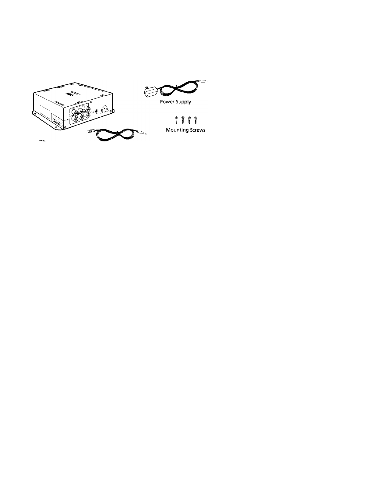
Inspection
Your MRD-Dl multi-room distribution system consists of a modulator
unit, a power supply, two IR emitter assemblies, an IR target, four
mounting screws, and a channel tuning tool as shown.
Modulator Unit
IR Target IR Emitter (2) Tuning Tool
Introduction
Page 6

Preparation for Use
Before installing your MRD-Dl, please read the following brief
discussion of its parts and what they do:
Modulator Unit
The modulator unit accepts the video input from your Sony DSS
receiver and one other video device of your choosing (VCR, laserdisc
player, etc.) and creates an "in-house" television channel for them. The
unit also accepts the input from an off-air antenna or cable service and
provides some amplification of the signal. The outputs from the
modulator unit can be connected to up to five TVs: two located within
30 ft. of the unit, and three located within 100 ft. of the unit. When
connected to remote TVs, a Sony IR target EAC-Tl must be used in
order to use your remote control.
Power Supply
The MRD-Dl is designed to operate from a 12 V AC power source. The
power supply provided with your system will make the necessary
voltage conversions when connected to 110 V AC, 60 Hz power.
Under no circumstances should you substitute the power supply
provided with MRD-Dl.
IR Emitters
There are two IR emitters provided with MRD-Dl. The IR emitters
connect to the modulator unit and are to be placed over the IR receiver
located on the video sources. One emitter is provided for each source.
IR Target
One IR target is provided with MRD-Dl. The IR target is to be installed
in a remote viewing room and is connected to the modulator urrit via a
75-ohm coaxial cable. This IR target must be exposed so you can point
your remote control at it.
Introduction
Page 7

Installation Instructions
1 Make certain that your present system is functioning correctly
prior to installing MRD-Dl. Ensure that all antenna or cable
signals are being received on all TVs that will be connected to
MRD-Dl.
2 Determine whether your home TV service is cable (CATV) or off-
air (anterma).
Note
• You should make written notes on this step so that you can refer to
them later.
□ If cable: determine the highest charmel number delivering a
-^cture signal, excluding channels 95-99. If uncertain, contact
your local cable company.
□ If antenna: time the TV one channel at a time from channel 14
to channel 36. Write down the channel number of each channel
that has no trace of a picture.
3 Deternune which of the remote TVs will be provided with IR
control capability using the IR target provided with MRD-Dl.
Note
• You can, at a later time, move the target to another remote TV, or add
more IR targets. For now, you need to plan where the target will be
used.
4 Select an installation location for the modulator unit that satisfies
all of the following conditions:
□
is close to the DSS receiver and the second video source;
□
has 110 volt AC power within easy access;
□
can connect easily to the coaxial input that delivers either the
antenna or cable signal to the main TV;
permits connection of the IR emitters to the video sources
within the length of the emitter cable (6 ft.);
□
is clean and dry and likely to stay that way. Mounting near
window or door openings is strongly discouraged.
Installation Instructions
Page 8

Fasten the modulator unit to the desired location using the
mounting screws provided with the unit. The orientation is not
critical. Mounting that enables clear access to the top of the unit for
tuning and easy access to connectors on the left and right sides of
the unit is most desirable.
Connect the modulator unit to the video sources (when viewed
from the end, the video and audio input cormectors on the left are
for INPUT 1 and those on the right are for INPUT 2).
Connect the DSS receiver video and audio outputs to INPUT 1 and
the second video source (optional) to INPUT 2.
Video
(Yellow)
Audio L \anini Ibi
(White) Audio R
(Red)
jmii 1^1
* 1 ^
z
I- 1
Video
(Yellow)
i=CZBro°<
Audio R
(Red)
Audio L
(White)
7 Connect the coaxial cable from the antenna or the cable source
directly to the modulator unit using the connector labeled RF IN.
8 Connect the main TV to the modulator unit using a coaxial cable
between the VHF/UHF input of the TV and one of the cormectors
labeled LOCAL RF OUT on the modulator unit.
Note
• Whe7t the second video source is a VCR, connect the other LOCAL RF OUT
connector to the VCR input connector using a coaxial cable.
8 Installation Instructions
Page 9

9 Connect the IR emitters to the modulator unit. With firm pressure,
place one of the adhesive backed IR emitters over the remote
sensor on the DSS receiver. Repeat the procedure for the second
video source.
DSS Receiver
Note
• You may have to refer to the owners manual of the second video
source to determine the location of its remote sensor.
Your modulator unit is now ready for use and can be turned on,
tuned and tested without connecting the remote TVs. If you wish
to turn on now, proceed to the section of this manual dealing with
set-up and tuning the modulator unit on page 11. If you wish to
connect the remote TVs now, proceed to page 10.
Installation Instructions
Page 10

Connecting the Remote TVs
1 MRD-Dl will support (provide signal for, and IR remote control of
two video sources for) five remote TV locations. Connect the
modulator unit directly to each TV via a 75-ohm coaxial cable and
an IR target.
Notes
• Additional IR targets can be added as desired. They are available from
your Sony dealer.
• If the system is improperly tuned, the power indicator will blink. Do
not ignore a blinking power indicator even if the TV is showing a
picture. Repeat the tuning procedure.
10 Installation Instructions
Page 11

Setting up and Tuning the Modulator
Perform the following steps after your multi-room distribution system
has been connected properly.
1 Connect the output (mini-jack) of the power supply to the modulator
unit and plug the power supply into a 110 V AC wall outlet.
The green LED Power indicator should illuminate. If it does not,
recheck all power connections.
2 Turn on the main TV. The mode of your TV (CATV or antenna)
will determine the "in-house" channels you will use.
□ If antenna, you will use UHF channels between 14 and 35
inclusively.
□ TF cable, you will use CATV channels between 54 and 86
inclusively.
Refer to your notes made of channels delivered to your home
(page 7).
3 Select your "in-house" channels and make a written note of what
they will be. Select a charmel for the second video source even if
one will not be used.
□ For CATV: use channels higher than that of your notes.
Highest Channel
34
65 67
□ For antenna: select any bf the' unused channels provided that
they are at least one unused channel apart from one another and
at least one unused channel away from a channel with a picture.
Highest Channel
15,16,17, 20,
24,25,26
14,15,19,20, 21
Set INPUT 1
54
Set INPUT 1 Set INPUT 2
16
14 20
Installation Instructions 11
Set INPUT 2
56
69
26
Page 12

Note
• INPUT 2 must be higher than INPUT 1 when using CATV channels,
and INPUT 1 and INPUT 2 must be separated by at least one unused
channel.
• If the MRD-Dl is improperly tuned, the power indicator will blink. Do
not ignore a blinking power indicator even if the TV is showing a
picture. Repeat the tuning procedure until the power indicator is
steady on.
4 Tune your TV to the channel you selected for INPUT 1. Turn on
the DSS receiver.
5 Using the tuning tool provided, turn the first two rotary controls
on the top of the modulator unit to the channel number selected in
step 3. Begin the tuning process by setting the first digit of the
channel with the first rotary control, and then the second digit of
the charmel with the second rotary control. Tune only one channel
at a time.
\
MODULATOR
LINE 1
LINE 2
3
%
When the channel is selected, the main TV should be displaying a
picture. This confirms proper operation and channel tuning. The
DSS channel will now be available on every TV connected to the
system.
Repeat steps 4 and 5 using your second video source and your
selected INPUT 2 number. If there is no second source, set INPUT 1.
12 Installation Instructions
J
Page 13

System Diagram
A/V Cable
DSS Receiver
«TfUITE.« ^ ▼ ▼ ▼
nil 0 II ® .^.™c
lllllllllllll “y* a ® ¿ I
ÍW5 • ó ® ® ® ® @
V
- Audio/
Video Out
Hs:©"
©-□
*
A
•/
' Coaxial Cable
to VHF/UHF
Input
IR Target EAC-T1
(1 Supplied)
Coaxial Cable
to VHF/UHF
Input
Installation Instructions 13
Page 14

Common Questions
Can the modulator be connected to a remote TV without using an IR target?
Yes, but you won't have remote control capability. You can add an IR
target at any time to get remote control capability. If you add an IR
target, unplug the modulator unit before attaching it.
Can an amplifier be used on the output of the modulator to drive a signal over longer cable paths?
No. The IR remote control feature will be defeated if an external
amplifier is used.
Can I use any remote control with the IR target?
The remote control you use with the IR target must be capable of
operating the component you want to control. The Sony RM-Y130
remote commander can control a DSS receiver, TV, VCR, cable box, and
laserdisc player, and has a learning feature for non-preprogrammed
components.
Can a splitter be used on one or more of the remote video outputs
to operate multiple TV's on that line?
No. The MRD-Dl Multi-room Distribution System is a pre-engineered
system providing optimum signal levels to each TV for clear, crisp
picture quality. Each time a splitter is added there is lowering of signal
level called insertion loss. Insertion losses upset system performance.
Additionally, not all splitters pass DC voltage. Inability to pass DC
voltage will cause the IR feature to be defeated.
Can I change from the off-air antenna to cable without problems?
Yes. Even though cable channels are set at different frequencies than
off-air channels, MRD-Dl will accommodate and work with either. If
you change from one signal source to the other, you will have to retime
your system following the procedures of this manual.
14 Common Questions
Page 15

Specifications
General
Size (H/W/D)
Mass
Power
Performance
Signal Inputs
Signal Outputs
RF carriers
RF Power Output
Antenna Isolation
172 X 140 X 51 mm (6.8 x 5.5 x 2.0 in.)
1.19 kg (2 lbs, 10 oz.)
Transformer Input: 115 VAC, 60 Hz
Transformer Output: 12 VAC, 60 Hz
Consumption: 7 watts, typical
1 for CATV or Antenna
2 for video devices such as satellite receiver, VCR
or laserdisc player
5 for connecting to main TV, input to VCR and up
to 3 remote TVs
Note: All outputs support IR operation of remote
devices when cormected to a target assembly.
Stability ±1 kHz
Frequency ranges: UHF channels 14 to 35
CATV channels 54 to 86
Charmel width: 6.0 MHz
Audio offset: 4.5 MHz
Sidebands: Double
Modulator: 12.0 dBmV nominal (4000 pvolts)
15.5 dBmV maximum (5670 pvolts)
Greater than 60 dB
Video Performance
Differential Gain: 4%, typical
Differential Phase error: 4°, typical
Signal to Noise Ratio
Input Signal Level
45 dB, typical
Video: 1.0 volt peak to peak into 75 Q
Audio: 2.8 volt peak to peak into 47 kQ
Controls and Indicators
Function
Control/Indicator Type
Output Channel Select Four rotary indicators:
one (1) pair for each
output channel.
Power On/Off
IR System Enabled
Green LED Indicator
Red LED Indicator
Purpose
Select output channel.
a) Confirms power
applied.
b) Blinks to aid channel
selector positioning.
a) Confirms IR repeater
system enabled.
15
Page 16

Limited Warranty
If this product should prove defective in workmanship or material
during the period of one (1) year from the date of original purchase at
retail, the same will be replaced by either the Seller, or Sony Electronics
Inc.
SUCH REPLACEMENT SHALL BE THE SOLE REMEDY OF THE
CONSUMER, AND THERE SHALL BE NO LIABILITY ON THE PART
OF THE MANUFACTURER, DISTRIBUTOR OR SELLER FOR ANY
LOSS OR DAMAGE, DIRECT OR CONSEQUENTIAL, ARISING OUT
OF THE USE OF, OR INABILITY TO USE, THIS PRODUCT. Some
states of the United States do not allow the exclusion of incidental or
consequential damages, so the above exclusion may not apply to you.
This warranty gives you specific rights and you may also have other
rights which vary from state to state.
To locate the servicer or dealer nearest you, for service assistance or
resolution of a service problem, or for product information or operation,
call:
SONY DIGITAL SATELLITE SYSTEM INFORMATION CENTER
1-800-838-7669
For an accessory or part not available from your authorized dealer, call:
1-800-488-SONY (7669)
Sony Corporation Printed in U.S.A.
 Loading...