

Sony MO DISK DRIVE SMO-F551, SMO-F561 User Manual
3-864-285-12(1)
SMO-F551
1998 by Sony Corporation Printed in Japan
MO Disk Drive
User’s Guide
Safety Regulations
Owner’s Record
The model and serial numbers are located on the top of the
drive. Record the serial number in the space provided
below.
Refer to them whenever you call upon your Sony dealer
regarding this product.
Model No. SMO-F551
Serial No._________________________
Information
You are cautioned that any changes or modifications not
expressly approved in this manual could void your
authority to operate this equipment.
WARNING
To prevent fire or shock hazard, do not expose the
unit to rain or moisture.
To avoid electrical shock, do not open the cabinet.
Refer servicing to qualified personnel only.
CAUTION
As the laser beam used in the SMO-F551 is harmful to
the eyes, do not attempt to disassemble the unit.
Refer servicing to qualified personnel only.
The use of optical instruments with this product will
increase eye hazard.
The use of controls or adjustments or performance of
procedures other than those specified herein may result
in hazardous radiation.
This MO drive is classified as a CLASS 1 LASER
PRODUCT.
CLASS 1
LASER PRODUCT
LASER KLASSE 1
PRODUKT
LASER RADIATION WHEN OPEN. AVOID DIRECT EXPOSURE TO BEAM.
RADIATIONS DU LASER EN CAS D'OUVERTURE, EVITER TOUTE EXPOSITION DIRECTE AU FAISCEAU.
LASERSTRAHLUNG, WENN ABDECKUNG GEÖFFNET. NICHT DEM STRAHL AUSSETZEN.
LASERSTRÅLING VED ÅBNING, UNDGÅ UDS/ETTELSE FOR STRÅLING.
LASERSTRÅLING NÅR DEKSEL ÅPNES, UNNGÅ EKSPONERING FOR STRÅLEN.
LASERSTRÅLNING NÄR DENNA DEL ÄR ÖPPNAD, STRÅLEN ÄR FARLIG.
AVATTAESSA OLET ALTTIINA LASERSÄTEILYLLE, ÄLÄ KATSO SÄTEESEN.
DANGER
DANGER
VORSICHT
ADVARSEL
ADVARSEL
VARNING
VARO!
LUOKAN 1 LASERLAITE
KLASS 1 LASER APPARAT
VAROITUS!
Laitteen käyttäminen muulla kuin tässä käyttöohjeessa
mainitulla tavalla saattaa altistaa käyttäjän
turvallisuusluokan 1 ylittävälle näkymättömälle
lasersäteilylle.
VARNING
Om apparaten används på annat sätt än i denna
bruksanvisning specificerats, kan användaren utsättas för
osynlig laserstrålning, som överskrider gränsen för
laserklass 1.
LASER RADIATION WHEN OPEN. AVOID DIRECT EXPOSURE TO BEAM.
RADIATIONS DU LASER EN CAS D'OUVERTURE, EVITER TOUTE EXPOSITION DIRECTE AU FAISCEAU.
LASERSTRAHLUNG, WENN ABDECKUNG GEÖFFNET. NICHT DEM STRAHL AUSSETZEN.
LASERSTRÅLING VED ÅBNING, UNDGÅ UDS/ETTELSE FOR STRÅLING.
LASERSTRÅLING NÅR DEKSEL ÅPNES, UNNGÅ EKSPONERING FOR STRÅLEN.
LASERSTRÅLNING NÄR DENNA DEL ÄR ÖPPNAD, STRÅLEN ÄR FARLIG.
AVATTAESSA OLET ALTTIINA LASERSÄTEILYLLE, ÄLÄ KATSO SÄTEESEN.
DANGER
DANGER
VORSICHT
ADVARSEL
ADVARSEL
VARNING
VARO!
Denne merkelappen er festet på apparatets innside.
Denna varningsskylt finns inuti apparaten.
Denne mærkat sidder indeni apparatet.
Tmä tarra on kiinnitetty laitteen sisään.
Tekniske Data
■ Laser
Type Halveder GaAlAs
laser
Bølgelengde 685 nm ± 10 nm
Maksimum utgang 30 mW
Specifikationer
■ Laser
Typ Halvledarlaser av typ
GaAlAs
Våglängd 685 nm ± 10 nm
Maximal uteffekt 30 mW
Specifikationer
■ Laser
Type Halvlederlaser
GaAlAs laser
Bølgelængde 685 nm ± 10 nm
Max. udgangseffekt 30 mW
Diese Ausrüstung erfüllt die Europäischen EMCBestimmungen für die Verwendung in folgender /
folgenden Umgebung(en):
• Wohngegenden
• Gewerbegebiete
• Leichtindustriegebiete
(Diese Austüstung erfüllt die Bestimmungen der Norm
EN55022, Klasse B.)
Precautions
Safety Considerations
■ Power supply
• Be sure to use +5 V, +12 V DC.
Damage Prevention
■ Do not subject the drive to shock or vibration
■ Location requirements
Careful consideration should be given to the following in
selecting a site to install or store your drive.
Avoid the following conditions:
• High humidity
• High temperatures
• Direct sunlight
• Dust
• Strong vibration
• Wide temperature fluctuations
■ Moving the drive
Be sure to remove the disk cartridge when the drive is not
being used. Also never move or transport the drive with the
disk cartridge still inserted.
■ If problems occur
If any problems occur, turn off the power and unplug the
drive, contact your dealer.
Warning about Cleaning
In the drive, preventive measures are taken to guard against
dust. It is unnecessary to clean the optical lens of your
drive. Using a lens cleaning cartridge may damage the
drive.
Cooling Requirements
Forced-air cooling is required throughout the drive,
preventing overheat of the drive mechanism and electrical
components. Forced-air cooling must be provided as a
system integration.
This maximum temperature is applicable to all operating
conditions specified in this manual.
Measuring Point Maximum Temperature
Disk Cartridge 55 °C (131 °F)
The temperature conditions specified in this
manual must always be met for the SMO-F551 to
function properly.
This label is located on the
top of the drive unit
enclosure.
Dieses Etikett befindet sich
auf der Oberseite des
Laufwerksgehäuses.
This label is located
on the drive unit’s
internal chassis.
Dieses Etikett
befindet sich auf dem
inneren Chassis des
Laufwerkes.
DANGER
LASER RADIATION WHEN OPEN.
AVOID DIRECT EXPOSURE TO BEAM.
DANGER
RADIATIONS DU LASER EN CAS D’OUVERTURE.
EVITER TOUTE EXPOSITION DIRECTE AU FAISCEAU.
VORSICHT LASERSTRAHLUNG. WENN ABDECKUNG
GEöFFNET. NICHT DEM STRAHL AUSSETZEN.
■ Operating environment
Installation ±10°
Temperature
Operating 5 °C to 45 °C
(gradient 10° C/h or 18 °F/h)
Relative humidity
Operating 10 % to 90 % (no condensation)
■ Power supply and others
Power supply +5 V ±5%, 0.8 A (typ.)
+12 V ±5%, 0.9 A (typ.)
Dimensions 41.3 × 146.0 × 203.0 mm (H ×W×D)
(without Front Panel)
Weight 1.5 kg
Design and specifications are subject to change without
notice.
■ Compatible Media
SMO-F551 is compatible with the following 5 1/4 inch
(130 mm) Magneto Optical Disks.
Compatibility
Type Description ISO Standard
Read Write
®®8× R/W 5.2GB 2048 bytes/sector ISO/IEC 15286
®®8× R/W 4.8GB 1024 bytes/sector (working draft)
®®8× R/W 4.1GB 512 bytes/sector
®®8× WO 5.2GB 2048 bytes/sector
®®8× WO 4.8GB 1024 bytes/sector
®®8× WO 4.1GB 512 bytes/sector
®®4× R/W 2.6GB 1024 bytes/sector ISO/IEC 14517
®®4× R/W 2.3GB 512 bytes/sector
®®4× WO 2.6GB 1024 bytes/sector
®®4× WO 2.3GB 512 bytes/sector
®®4× DOW 2.6GB 1024 bytes/sector
®®4× DOW 2.3GB 512 bytes/sector
® × 2× R/W 1.3GB 1024 bytes/sector ISO/IEC 13549
® × 2× R/W 1.2GB 512 bytes/sector
® × 2× WO 1.3GB 1024 bytes/sector
® × 2× WO 1.2GB 512 bytes/sector
® × 1× R/W 650MB 1024 bytes/sector ISO/IEC 10089
® × 1× R/W 594MB 512 bytes/sector
® × 1× WO 650MB 1024 bytes/sector ISO/IEC 11560
® × 1× WO 594MB 512 bytes/sector
W/R : Rewritable, WO : Write-Once, DOW : Direct Overwrite
Specifications
Switch setting and Assignments
Configuration and Location of Parts
SCSI Terminator
SMO-F551 features an internal SCSI bus terminator. When
the drive is connected at the end of the SCSI chain,
functional switch #11 (Enable Terminator) may be used to
terminated the SCSI connection.
For a single ended cable, 50-signal conductor flat cable or a
25-signal twisted cable can be used. The cable length shall
not exceed six meters.
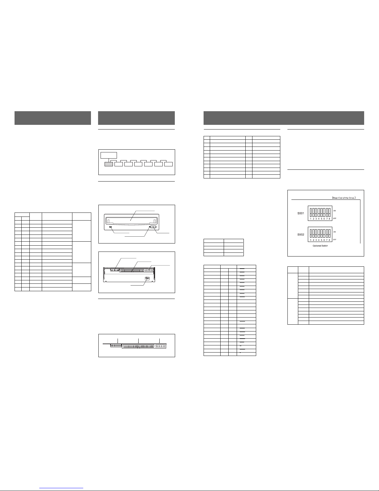
Optional Switch Setting
SMO-F551 features Optional Switch S501 and S502.
These two optional dip switches allow the user to set the
drive configurations.
Top Panel View
Optional Dip Switch Assignments
Optional Switch
Description
Switch Number
1 Reserved
2 Reserved
3 Disable Command Eject
S501 4 Reserved
5 Reserved
6 Reserved
7 Disable Write Cache
8 Disable Auto Spin-up
1 Reserved
2 Reserved
3 Reserved
S502 4 Reserved
5 Disable SCAM Selection
6 Reserved
7 Reserved
8
Enable Write Cache for Write and Verify Command
System Configuration
SMO-F551 is connected to a host computer through its
SCSI interface. The maximum of seven peripheral devices
can be linked as a daisy chain on the SCSI bus.
Host Computer
SCSI Cable
SMO-F551 SCSI peripheral devices
System Configuration Example
Location of Parts
This section provides a general description of the SMOF551 Magneto-Optical disk drive.
Front Panel
Disk Insertion Slot
Eject Button
Emergency Eject Hole
BUSY Indicator
Front View
Rear Panel
Functional Switch
GND Terminal
DC Power Connector
SCSI Connector
Rear View
SCSI and DC Power Connector
The SCSI and DC Power Connector is located at the upper
rear of the drive. The drive uses a Molex 53450-5431
combination 50 pin SCSI and 4 pin DC Power male header.
Recommended female connectors:
SCSI connector: 3M type number 7950-6500
DC Power connector: AMP 1-480424-0 MATE-N-LOCK
Functional Switch SCSI Connector DC Power Connector
49
A1
2501
1
A12
4
B1
B12
SCSI and DC Power Connector
Functional Switch Connector Pin Assignments
A1 SCSI ID2 B1 GND
A2 SCSI ID1 B2 GND
A3 SCSI ID0 B3 GND
A4 Disable SCSI Parity B4 GND
A5 Disable Write Cache B5* Reserved
A6 Disable Auto Spin-up B6* Reserved
A7 Force Verify for Write command B7* Reserved
A8 Disable Manual Eject B8* Reserved
A9 Enable Fast SCSI B9* Reserved
A10 Device Type B10* Reserved
A11 Enable Termination B11 GND
A12 Terminator Power B12 Terminator Power Source
* This pin is NOT directly connected to the GND. Do not use this pin as
GND. SMO-F551 drives the signal to GND level depending on the
functional switch setting. Otherwise, the signal is not driven to GND
level.
WARNING: Write cache is enabled as default
setting. The integrity of the buffer memory content
is not guaranteed through power cycling.
Caution: “Disable Write Cache” setting works as an ”OR”
function with the optional dip switch setting.
Caution: When the Fast SCSI function is used, it is
recommended that the host system and SCSI cables should
conform to the Fast SCSI.
DC Power Connector Pin Assignments
Pin Number Description
1 DC +12V
2 +12V Return
3 +5V Return
4 DC +5V
Pin Assignments of SCSI Connector
Signal Name Pin No. Signal Name
GND 1 2 DB0
GND 3 4 DB1
GND 5 6 DB2
GND 7 8 DB3
GND 9 10 DB4
GND 11 12 DB5
GND 13 14 DB6
GND 15 16 DB7
GND 17 18 DBP
GND 19 20 GND
GND 21 22 GND
GND 23 24 GND
OPEN 25 26 (TERM PW)
GND 27 28 GND
GND 29 30 GND
GND 31 32 ATN
GND 33 34 GND
GND 35 36 BSY
GND 37 38 ACK
GND 39 40 RST
GND 41 42 MSG
GND 43 44 SEL
GND 45 46 C/D
GND 47 48 REQ
GND 49 50 I/O
The bar “—” above the signal indicates active low.
 Loading...