

Page 1

Home Theater
System
4-230-773-12(1)
Operating Instructions
Mode d’emploi
Gebruiksaanwijzing
Bruksanvisning
GB
FR
NL
SE
HT-K215
2000 Sony Corporation
Page 2

WARNING
To prevent fire or shock
hazard, do not expose
the unit to rain or
moisture.
To avoid electrical shock, do not open
the cabinet. Refer servicing to qualified
personnel only.
Precautions
On safety
• Should any solid object or liquid fall into
the cabinet, unplug the amplifier and
have it checked by qualified personnel
before operating it any further.
On power sources
• Before operating the amplifier, check that
the operating voltage is identical with
your local power supply. The operating
voltage is indicated on the nameplate at
the bottom of the amplifier.
• The amplifier is not disconnected from
the AC power source (mains) as long as
it is connected to the wall outlet, even if
the amplifier itself has been turned off.
• If you are not going to use the amplifier
for a long time, be sure to disconnect the
amplifier from the wall outlet. To
disconnect the mains lead, grasp the
plug itself; never pull the cord.
• The AC power cord (mains lead) must be
changed, at a qualified service shop only.
• The mains switch is located on the front
exterior.
On placement
• Do not install the appliance in a confined
space, such as a bookcase or built in
cabinet.
• Place the amplifier in a location with
adequate ventilation to prevent heat
buildup and prolong the life of the
amplifier.
• Do not place the amplifier near heat
sources, or in a place subject to direct
sunlight, excessive dust or mechanical
shock.
• Do not place anything on top of the
cabinet that might block the ventilation
holes and cause malfunctions.
• Do not set the speakers in an inclined
position.
• Do not place the speakers in locations
that are:
– Extremely hot or cold
– Dusty or dirty
– Very humid
– Subject to vibrations
– Subject to direct sunlight
On operation
• Before connecting other components, be
sure to turn off and unplug the amplifier.
• Do not drive the speaker system with a
continuous wattage exceeding the
maximum input power of the system.
• If the polarity of the speaker connections
are not correct, the bass tones will be
weak and the position of the various
instruments obscure.
• Contact between bare speaker wires at
the speaker terminals may result in a
short-circuit.
• The speaker grille cannot be removed.
Do not attempt to remove the grille on
the speaker system. If you try to remove
it, you may damage the speaker.
If you encounter color irregularity on a
nearby TV screen
This speaker system is magnetically
shielded to allow it to be installed near a
TV set. However, color irregularities may
still be observed on certain types of TV
sets.
If color irregularity is observed…
p Turn off the TV set once, then turn it
on again after 15 to 30 minutes.
If color irregularity is observed again…
p Place the speakers further away from
the TV set.
If howling occurs
Reposition the speakers or turn down the
volume on the amplifier.
On cleaning
• Clean the cabinet, panel and controls
with a soft cloth slightly moistened with
a mild detergent solution. Do not use
any type of abrasive pad, scouring
powder or solvent such as alcohol or
benzine.
If you have any question or problem
concerning your amplifier, please
consult your nearest Sony dealer.
GB
2
Page 3
About This Manual
Conventions
• The instructions in this manual describe the controls on
the amplifier and speakers. You can also use the
controls on the supplied remote if they have the same or
similar names as those on the amplifier.
• The following icon is used in this manual:
z Indicates hints and tips for making the task easier.
This amplifier incorporates Dolby* Digital and Pro Logic
Surround and the DTS** Digital Surround System.
Manufactured under license from Dolby Laboratories.
*
“Dolby”, “AC-3”, “Pro Logic” and the double-D symbol a are
trademarks of Dolby Laboratories.
Confidential unpublished Works. © 1992-1997 Dolby Laboratories.
All rights reserved.
Manufactured under license from Digital Theater Systems, Inc. US
**
Pat. No. 5,451,942 and other worldwide patents issued and pending.
“DTS” and “DTS Digital Surround” are trademarks of Digital
Theater Systems, Inc. © 1996 Digital Theater Systems, Inc. All
rights reserved.
Demonstration Mode
The demonstration will activate the first time you turn on the
power. When the demonstration starts, the following message
appears in the display :
“NOW DEMONSTRATION MODE IF YOU FINISH
DEMONSTRATION PLEASE PRESS POWER KEY
WHILE THIS MESSAGE APPEARS IN THE DISPLAY
THANK YOU”
To cancel the demonstration
Press ?/1 to turn the amplifier off while the above message is
being displayed. The next time you turn the amplifier on, the
demonstration will not appear.
To view the demonstration
Hold down SET UP and press ?/1 to turn on the power.
Notes
• Running the demonstration will clear the amplifier’s
memory. For details on what will be cleared, see “Clearing
the amplifier's memory” on page 14.
• There will be no sound when the demonstration mode is
activated.
TABLE OF CONTENTS
Hooking Up the Components 4
Unpacking 4
Setting Up the Amplifier 5
Video Component Hookups 6
Digital Component Hookups 7
5.1CH/SAT Hookups 8
Other Hookups 9
Hooking Up and Setting Up the
Speaker System 10
Speaker System Hookup 11
Performing Initial Setup Operations 14
Multi Channel Surround Setup 15
Before You Use Your Amplifier 20
Location of Parts and Basic
Operations 21
Front Panel Parts Descriptions 21
Enjoying Surround Sound 23
Selecting a Sound Field 24
Understanding the Multi-Channel Surround
Displays 27
Customizing Sound Fields 29
Other Operations 32
Using the Sleep Timer 33
Additional Information 34
Troubleshooting 34
Specifications 36
Glossary 38
Settings Using SURR, LEVEL, and SET UP
buttons 39
Remote Button Description 40
Index 42
GB
GB
3
Page 4
Hooking Up
Unpacking
the
Components
This chapter describes how to connect
various audio and video components
to the amplifier. Be sure to read the
sections for the components you have
before you actually connect them to
the amplifier.
Check that you received the following items with the
amplifier:
• Remote commander (remote) (1)
• Size AA (R6) batteries (2)
• Speakers
• Front speakers (2)
• Rear speakers (2)
• Center speaker (1)
• Subwoofer (1)
• Speaker connecting cord, long (2)
• Speaker connecting cord, short (3)
• Monaural connecting cord (1 phono to 1 phono) (1)
• Foot pads (20)
• Screw (1)
• Amplifier stand (1)
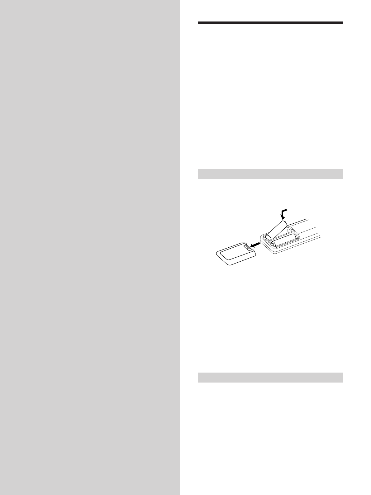
Inserting batteries into the remote
Insert R6 (size-AA) batteries with the + and – properly
oriented in the battery compartment. When using the
remote, point it at the remote sensor g on the amplifier.
]
}
}
]
z
When to replace batteries
Under normal conditions, the batteries should last for about 6
months. When the remote no longer operates the amplifier,
replace all batteries with new ones.
Notes
• Do not leave the remote in an extremely hot or humid place.
• Do not use a new battery with an old one.
• Do not expose the remote sensor to direct sunlight or lighting
apparatuses. Doing so may cause a malfunction.
• If you don’t use the remote for an extended period of time,
remove the batteries to avoid possible damage from battery
leakage and corrosion.
Before you get started
• Turn off the power to all components before making
any connections.
• Do not connect the AC power cords until all of the
connections are completed.
• Be sure to make connections firmly to avoid hum and
noise.
• When connecting an audio cord, be sure to match the
color-coded pins to the appropriate jacks on the
components: white (left, audio) to white; and red (right,
audio) to red.
GB
4
Page 5
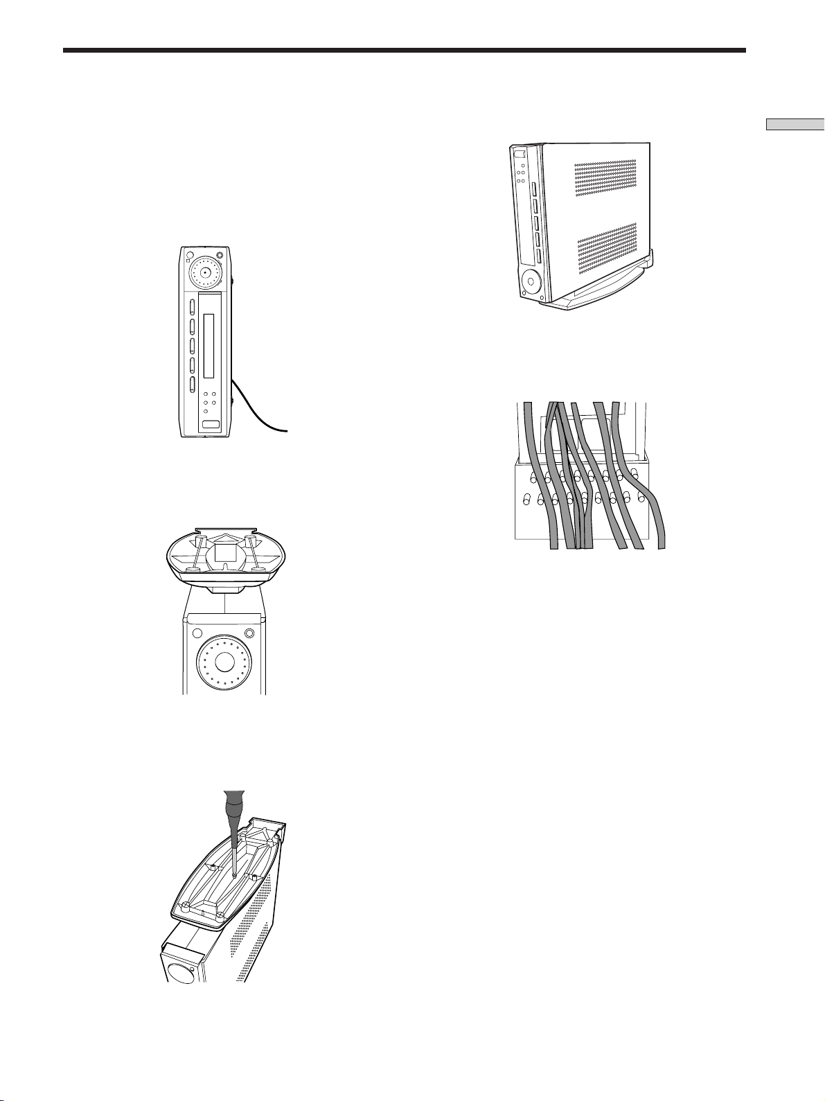
Setting Up the Amplifier
You can place the amplifier flat on a surface or on the
amplifier stand. Make sure that you do not place anything
on top of the amplifier.
1 Turn the amplifier to its side.
Be sure to place the amplifier with the ?/1 (power)
button at the bottom.
R
SOUND FIELD MODE
MASTER VOLUME
–+
VIDEO TV DVD AUX 5.1CH/SAT
+–
SURR LEVEL SET UP
?/1
2 Place the amplifier stand on top of the amplifier.
Be sure to align the hole on the stand to the hole on the
amplifier.
5 Place the amplifier stand on a flat surface.
Hooking Up the Components
Note
You can dress the power cord and other wires at the amplifier
stand as shown below.
3 Press to insert the stand to the amplifier.
4 Insert the screw and tighten it.
GB
5
Page 6
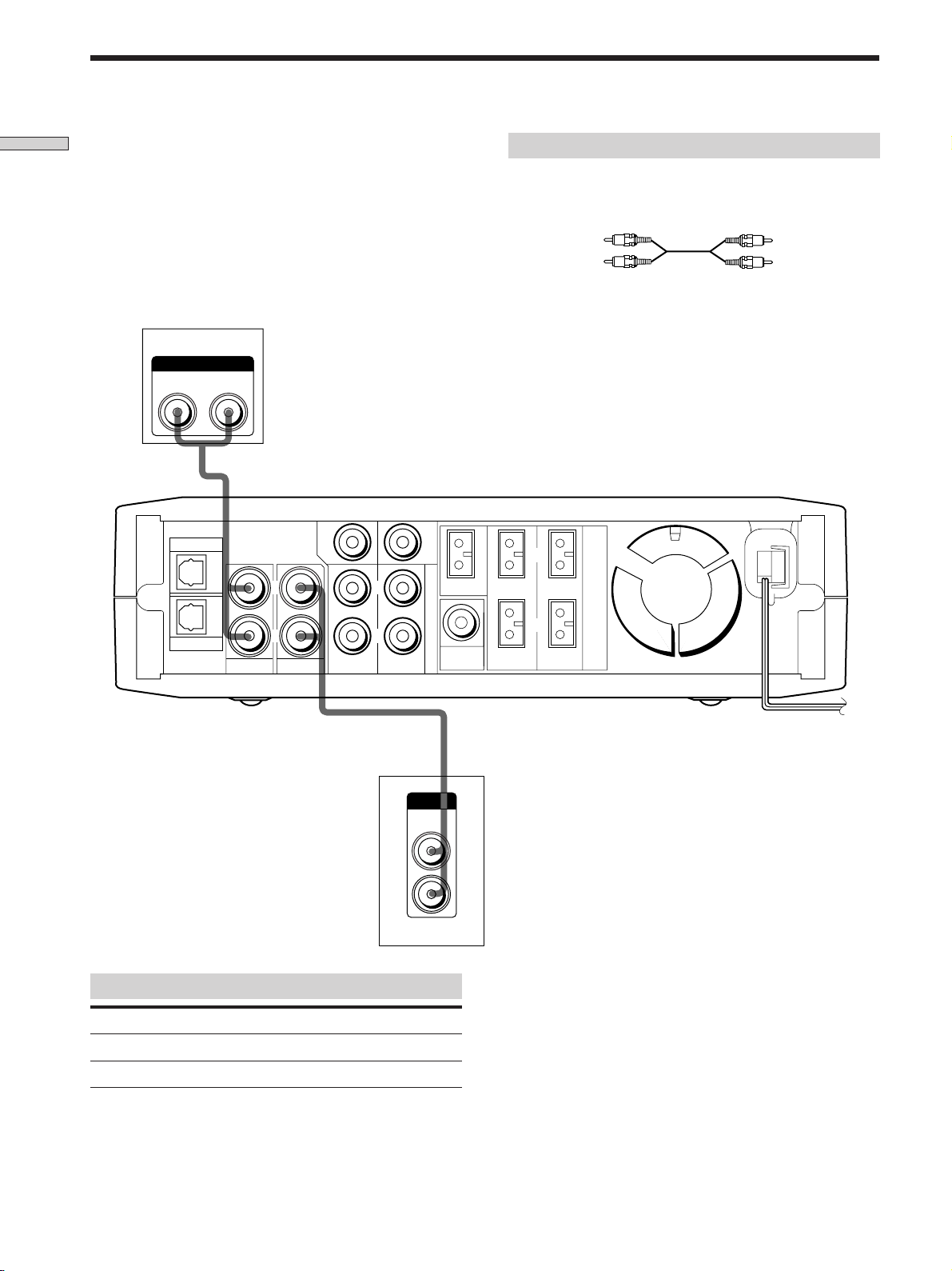
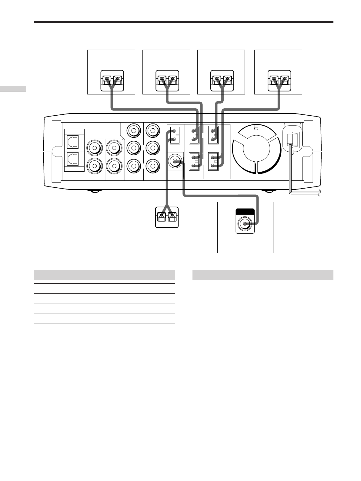
Video Component Hookups
Hooking Up the Components
TV
OUTPUT
AUDIO OUT
RL
DVD
Required cords
Audio cord (not supplied)
When connecting a cord, be sure to match the color -coded pins
to the appropriate jacks on the components.
White (L)
Red (R)
OUTPUT
AUDIO OUT
CENTER
L
L
WOOFER
CENTER
5.1CH/SAT
IMPEDANCE USE 8-16 Ω
L
SPEAKERS
White (L)
Red (R)
AUX
TV VIDEO FRONT
R
R
REAR
Jacks for connecting video components
Connect a To the
TV TV jacks
VCR VIDEO jacks
ç
OUTPUT
AUDIO
OUT
VCR
WOOFER
OUT
L
R
R
FRONT REAR
ç
IN OUT
INPUT OUTPUT
AUDIO
IN
L
R
AUDIO
OUT
GB
6
Page 7
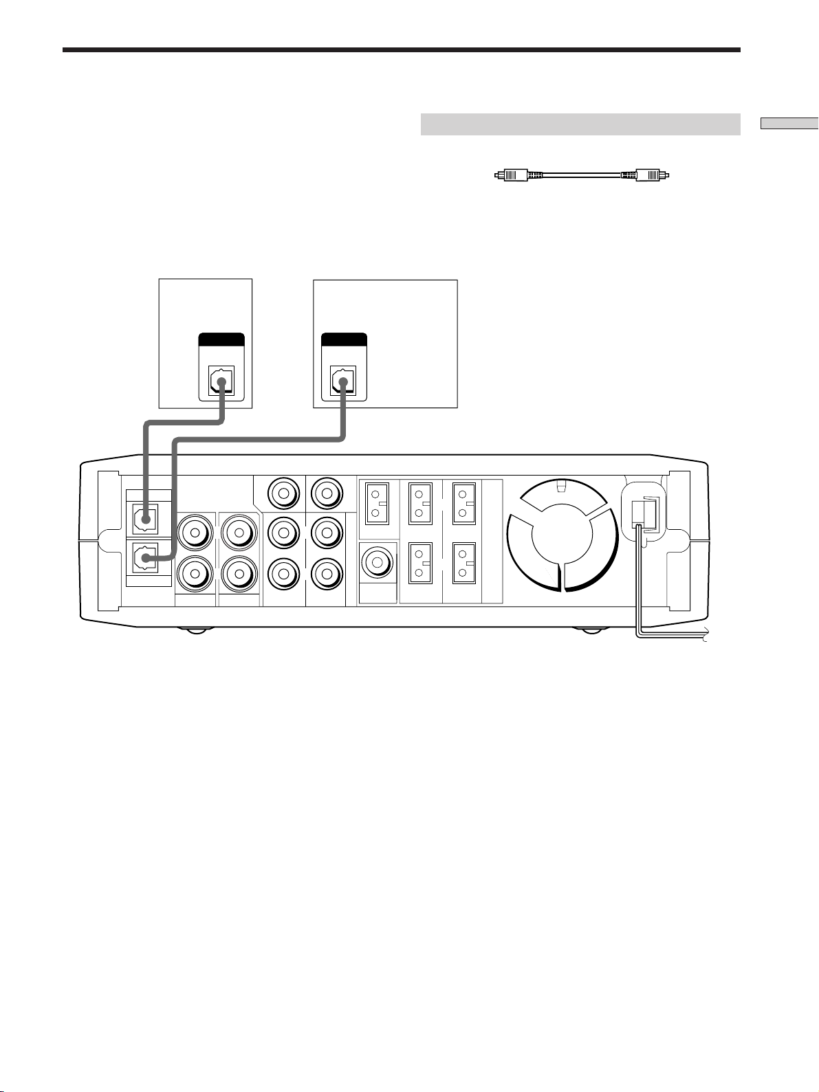
Digital Component Hookups
Connect the digital output jacks of your DVD player and
audio components (CD player, MD deck, etc.) to the
amplifier’s digital input jacks to bring the multi channel
surround sound of a movie theater into your home. To
enjoy full effect of multi channel surround sound, five
speakers (two front speakers, two rear speakers, and a
center speaker) and a sub woofer are required.
L
OUTPUT
DIGITAL
OPTICAL
CD player,
MD deck, etc.
WOOFER
5.1CH/SAT
DVD player
DVD
(etc.)
OUTPUT
DIGITAL
OPTICAL
CENTER
L
CENTER
Required cords
Optical digital cords (not supplied)
Black Black
Note
The optical digital input jacks on the amplifier are compatible
with sampling frequencies of 32 kHz, 44.1 kHz, 48 kHz and
96 kHz.
IMPEDANCE USE 8-16 Ω
L
SPEAKERS
Hooking Up the Components
AUX
TV VIDEO FRONT
R
R
WOOFER
REAR
Note
Connect the video jack of your DVD player to the VIDEO IN jack
of your TV.
OUT
R
FRONT REAR
GB
7
Page 8
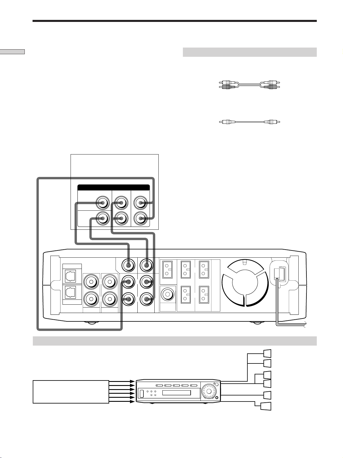
5.1CH/SAT Hookups
Hooking Up the Components
Although this amplifier incorporates a multi channel
decoder, it is also equipped with 5.1CH/SAT jacks. These
connections allow you to enjoy multichannel software
encoded in formats other than Dolby Digital (AC-3) and
DTS. If your DVD player is equipped with 5.1CH
OUTPUT jacks, you can connect them directly to the
amplifier to enjoy the sound of the DVD player’s multi
channel decoder. Alternatively, the 5.1CH/SAT jacks can
be used to connect an external multi channel decoder.
To fully enjoy multi channel surround sound, you will
need five speakers (two front speakers, two rear speakers,
and a center speaker) and a subwoofer. Refer to the
instruction manual supplied with your DVD player, multi
channel decoder, etc., for details on the 5.1 channel input
hookups.
CENTER
DVD player,
Multichannel decoder, etc.
5.1CH OUTPUT
REAR
FRONT
Required cords
Audio cords (not supplied)
Two for the 5.1CH/SAT FRONT and REAR jacks
White (L) White (L)
Red (R) Red (R)
Monaural audio cords (not supplied)
Two for the 5.1CH/SAT CENTER and WOOFER jacks
Black Black
Note
When using the connections described below, adjust the level of
your surround speakers, center speaker and subwoofer from the
DVD player or multichannel decoder.
WOOFER
REAR
WOOFER
CENTER
5.1CH/SAT
WOOFER
OUT
L
R
FRONT REAR
DVD
AUX
TV VIDEO FRONT
CENTER
L
R
L
R
Example of a DVD player hookup using the 5.1 CH/SAT jacks
5.1 CH/SAT
VIDEO TV DVD AUX 5.1CH/SAT
?/1
DVD player
Note
See page 11 for details on speaker system hookup.
SURR LEVEL SET UP
+–
IMPEDANCE USE 8-16 Ω
SPEAKERS
SPEAKERS
FRONT
MASTER VOLUME
R
SPEAKERS
REAR/CENTER
–+
SUB WOOFER
SOUND FIELD MODE
Front Speaker (L)
Front Speaker (R)
Rear Speaker (L)
Rear Speaker (R)
Center Speaker
Active Woofer
GB
8
Page 9
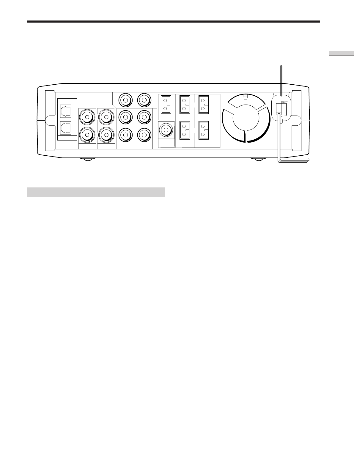
Other Hookups
REAR
WOOFER
CENTER
5.1CH/SAT
WOOFER
DVD
AUX
TV VIDEO FRONT
CENTER
L
R
L
R
Connecting the AC power cord
Before connecting the AC power cord of this amplifier to a
wall outlet:
• Connect the speaker system to the amplifier (see page
11).
OUT
L
R
FRONT REAR
IMPEDANCE USE 8-16 Ω
SPEAKERS
AC power cord
To a wall outlet
Hooking Up the Components
b
Connect the AC power cord(s) of your video components
to a wall outlet.
Note
If the AC power cord is disconnected for about two weeks, the
amplifier’s entire memory will be cleared and the demonstration
will start.
GB
9
Page 10

Hooking Up
SET UP
R
?/1
VIDEO TV DVD AUX 5.1CH/SAT
SURR LEVEL SET UP
+–
SOUND FIELD MODE
MASTER VOLUME
–+
and Setting Up
the Speaker
System
This chapter describes how to hook
up your speaker system to the
amplifier, how to position each
speaker, and how to set up your
speakers to enjoy multi channel
surround sound.
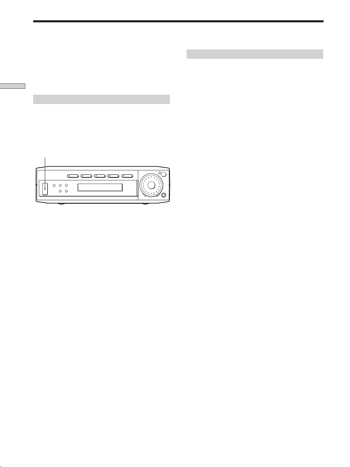
+/– buttons
Brief descriptions of buttons and control
used to set up the speaker system
SET UP button: Press to enter the setup mode when
specifying speaker types and distances.
+/– buttons: Use to select parameters after pressing the
SET UP button.
GB
10
Page 11
Speaker System Hookup
Required cords
Speaker connecting cords (supplied)
One white for SPEAKERS FRONT LEFT
One red for SPEAKERS FRONT RIGHT
One green for SPEAKERS CENTER
One blue for SPEAKERS REAR LEFT
One yellow for SPEAKERS REAR RIGHT
Hooking Up and Setting Up the Speaker System
(–)
(+)
Monaural connecting cord (supplied)
One for an active sub woofer
Black Black
Speaker plug
Notes
• Make sure that you insert the speaker connecting cords
according to the colour as labelled on the top of the amplifier of
the speaker plug ends.
• The polarity of the speaker plugs is fixed on the amplifier.
11
GB
Page 12
Speaker System Hookup
Front speaker (L)
}
]
Hooking Up and Setting Up the Speaker System
CENTER
DVD
L
R
AUX
TV VIDEO FRONT
L
R
Front speaker (R)
}
WOOFER
CENTER
5.1CH/SAT
WOOFER
REAR
OUT
}
Rear speaker (L)
]
FRONT REAR
}
L
R
]
IMPEDANCE USE 8-16 Ω
SPEAKERS
]
INPUT
Rear speaker (R)
}
]
Center speaker
Terminals for connecting the speakers
Connect the To the
Front speakers (8 ohm) SPEAKERS FRONT terminals
Rear speakers (8 ohm) SPEAKERS REAR terminals
Center speaker (8 ohm) SPEAKERS CENTER terminals
Active sub woofer WOOFER OUT jack
Active sub woofer
Notes on speaker system hookup
• Make sure the plus (+) and the minus (–) terminals on
the speakers are matched to the corresponding plus (+)
and minus (–) terminals on the speaker plugs.
• Make sure all connections are firm. Contact between
bare speaker wires at the speaker terminals may cause a
short-circuit.
Tip
All striped wires are plus (+) in polarity, and should be connected
to the plus (+) speaker terminals.
12
GB
Page 13
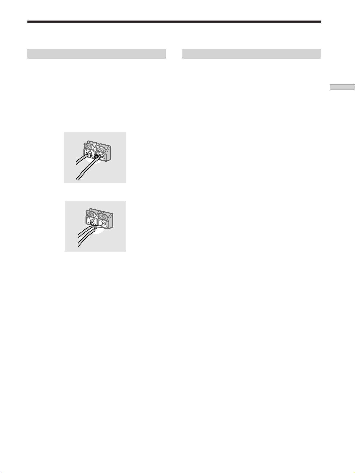
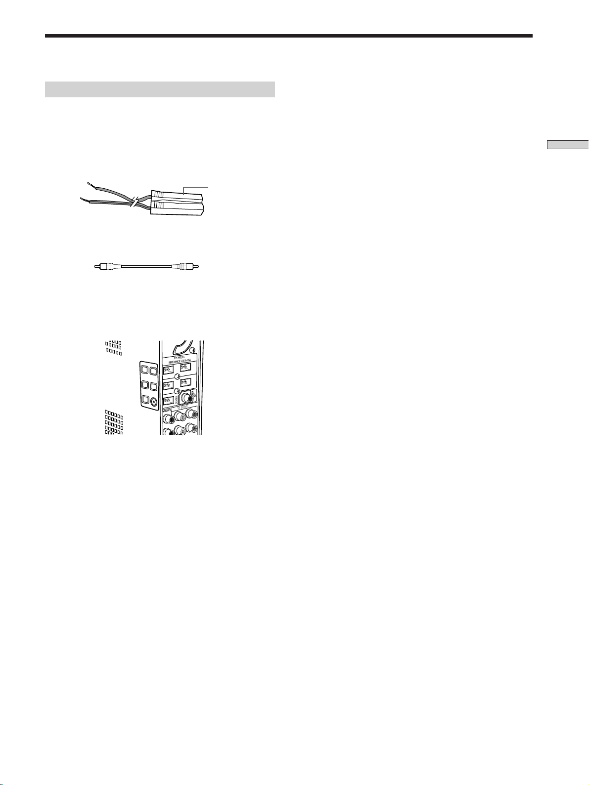
To avoid short-circuiting the speakers
Short-circuiting of the speakers may damage the
amplifier. To prevent this, make sure to take the following
precautions when connecting the speakers.
To avoid damaging your speakers
Make sure that you turn down the volume before you
turn off the amplifier. When you turn on the amplifier, the
volume remains at the level you turn off the amplifier.
Make sure the stripped ends of each speaker cord
does not touch another speaker terminal or the
stripped end of another speaker cord.
Examples of poor conditions of the speaker cord
Stripped speaker cord is touching another speaker terminal.
Stripped cords are touching each other due to excessive
removal of insulation.
Hooking Up and Setting Up the Speaker System
After connecting all the components, speakers,
and AC power cord, output a test tone to check
that all the speakers are connected correctly. For
details on outputting a test tone, see page 18.
If no sound is heard from a speaker while outputting a
test tone or a test tone is output from a speaker other than
the one whose name is currently displayed on the
amplifier, the speaker may be short-circuited. If this
happens, check the speaker connection again.
13
GB
Page 14
Performing Initial Setup Operations
Once you have made speaker connections and have
turned on the power for the first time, clear the
amplifier’s memory. After you have done this, set the
speaker sizes, speaker locations and other initial system
settings that are necessary.
Hooking Up and Setting Up the Speaker System
Clearing the amplifier’s memory
Before you use your amplifier for the first time or when
you want to clear the amplifier’s memory, do the
following.
If the Demonstration appears when the power is turned
on, this procedure is not necessary.
?/1
VIDEO TV DVD AUX 5.1CH/SAT
?/1
SURR LEVEL SET UP
+–
1 Turn off the amplifier.
MASTER VOLUME
R
–+
SOUND FIELD MODE
Setting up the amplifier
Before you use your amplifier for the first time, use the
SET UP button to adjust settings to correspond to your
system. You can set the following items. For details on
how to adjust each setting, see the page in parentheses.
• Set the speaker size (page 15).
• Set the speaker distance (page 17).
2 Hold down ?/1 for four seconds.
The currently selected function, then the
demonstration message appears in the display and the
items including the following are reset or cleared:
• All sound field parameters are reset to their factory
settings.
• All adjustments made with the SET UP button are
reset to their factory settings.
• The sound field memorized for each program source
is cleared.
14
GB
Page 15
Multi Channel Surround Setup
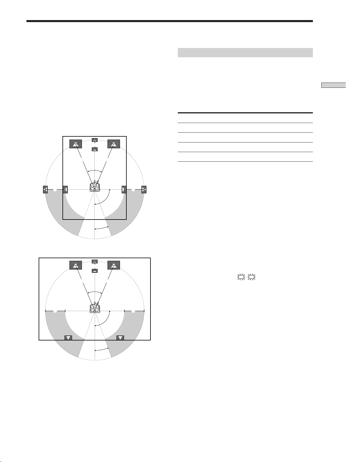
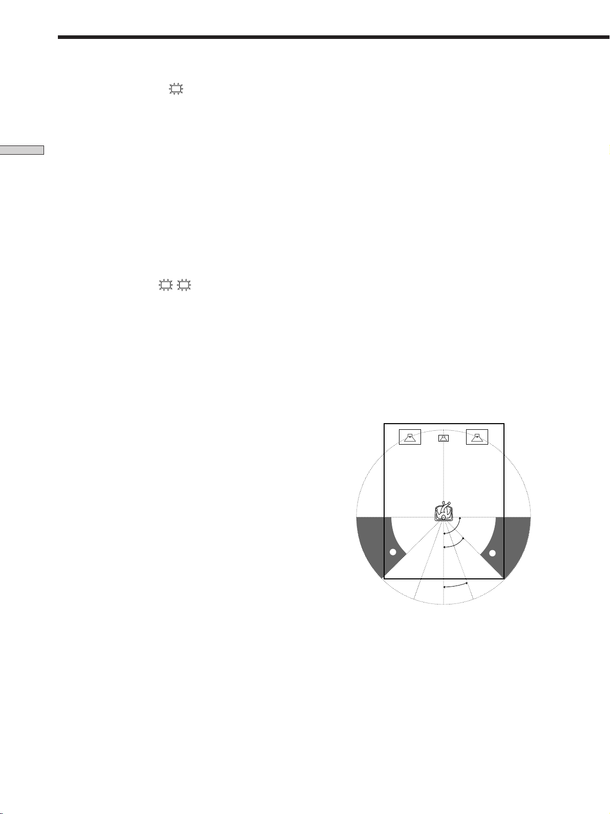
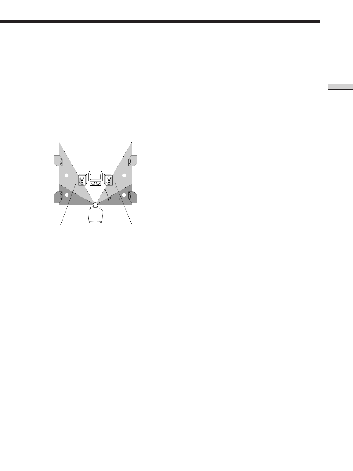
For the best possible surround sound all speakers should
be the same distance from the listening position (A).
(However, this unit lets you to place the center speaker up
to 1.5 meters (5 feet) closer (B) and the rear speakers up
to 4.5 meters (15 feet) closer (C) to the listening position.
The front speakers can be placed from 1.0 to 12.0 meters
(3 to 40 feet) from the listening position (A).)
You can place the rear speakers either behind you or to
the side, depending on the shape of your room (etc.).
When the rear speakers are placed to the side
B
A A
45°
CC
90°
20°
When the rear speakers are placed behind you
B
Specifying the speaker parameters
For HT-K215, the speaker size and sub woofer selection
has been preset to MICRO SP. (Micro Satellite Speaker)
according to the supplied speaker system. If you change
the speaker system, choose NORM. SP. (Normal Speaker)
to adjust the speaker size and sub woofer selection. When
you choose MICRO SP., the speaker size and the sub
woofer selection has been configurated as follows:
Speakers
Front
Center
Rear
Woofer
You cannot change the configuration if you choose MICRO SP.
Settings
SMALL
SMALL
SMALL
YES
1 Press ?/1 to turn on the amplifier.
2 Press SET UP repeatedly to select the parameter
you want to adjust.
3 Press +/– to select the setting you want.
The setting is stored automatically.
4 Repeat steps 2 and 3 until you have set all of the
parameters that follow.
The following speaker size setup is applicable for
NORM. SP.
Hooking Up and Setting Up the Speaker System
A A
45°
CC
90°
20°
Note
Do not place the center speaker farther away from the listening
position than the front speakers.
p Front speaker size (
L R
)
Initial setting : LARGE
• If you connect large speakers that will effectively
reproduce bass frequencies, select “LARGE”. Normally,
select “LARGE”.
• If the sound is distorted, or you feel a lack of surround
effects when using multi channel surround sound,
select “SMALL” to activate the bass redirection circuitry
and output the front channel bass frequencies from the
sub woofer.
• When the front speaker is set to “SMALL”, the center
and rear speakers are also automatically set to
“SMALL” (unless previously set to “NO”).
15
GB
Page 16
Multi Channel Surround Setup
p Center speaker size (
C
)
Initial setting : LARGE
• If you connect a large speaker that will effectively
reproduce bass frequencies, select “LARGE”. Normally,
select “LARGE”. However, if the front speakers are set
Hooking Up and Setting Up the Speaker System
to “SMALL”, you cannot set the center speaker to
“LARGE”.
• If the sound is distorted, or you feel a lack of surround
effects when using multi channel surround sound,
select “SMALL” to activate the bass redirection circuitry
and output the center channel bass frequencies from the
front speakers (if set to “LARGE”) or sub woofer. *
• If you do not connect the center speaker, select “NO”.
The sound of the center channel will be output from the
front speakers.*
2
p Rear speaker size (LS RS)
Initial setting : LARGE
• If you connect large speakers that will effectively
reproduce bass frequencies, select “LARGE”. Normally,
select “LARGE”. However, if the front speakers are set
to “SMALL”, you cannot set the rear speakers to
“LARGE”.
• If the sound is distorted, or you feel a lack of surround
effects when using multi channel surround sound,
select “SMALL” to activate the bass redirection circuitry
and output the rear channel bass frequencies from the
sub woofer or other “LARGE” speakers.
• If you do not connect rear speakers, select “NO”.*
z
About speaker sizes (LARGE and SMALL)
Internally, the LARGE and SMALL settings for each speaker
determine whether or not the internal sound processor will cut
the bass signal from that channel. When the bass is cut from a
channel the bass redirection circuitry sends the corresponding
bass frequencies to the sub woofer or other “LARGE” speaker.
However, since bass sounds have a certain amount of
directionality it best not to cut them, if possible. Therefore, even
when using small speakers, you can set them to “LARGE” if you
want to output the bass frequencies from that speaker. On the
other hand, if you are using a large speaker, but prefer not to
1
have bass frequencies output from that speaker, set it to
“SMALL”.
If the overall sound level is lower than you prefer, set all speakers
to “LARGE”.
p Rear speaker position (REAR PL.)*
Initial setting : BEHIND
This parameter lets you specify the location of your rear
speakers for proper implementation of the Digital Cinema
Sound surround modes in the “VIRTUAL” sound fields.
Refer to the illustration below.
• Select “SIDE” if the location of your rear speakers
corresponds to section A.
• Select “BEHIND” if the location of your rear speakers
corresponds to section B.
This setting only effects the surround modes in the
“VIRTUAL” sound fields.
3
z
*1~*3 correspond to the following Dolby Pro Logic modes
*1 NORMAL
*2 PHANTOM
*3 3 STEREO
90°
A
45°
B
20°
A
B
* These parameters are not available when “Rear speaker
size (REAR)” is set to “NO”.
16
GB
Page 17
p Rear speaker height (REAR HGT.)*
Initial setting : LOW
This parameter lets you specify the height of your rear
speakers for proper implementation of the Digital Cinema
Sound surround modes in the “VIRTUAL” sound fields.
Refer to the illustration below.
• Select “LOW” if the location of your rear speakers
corresponds to section A.
• Select “HIGH” if the location of your rear speakers
corresponds to section B.
This setting only affects the surround modes in the
“VIRTUAL” sound fields.
B
A
B
60
A
30
* These parameters are not available when “Rear speaker
size (REAR)“ is set to “NO”.
z
About the rear speaker position (SIDE, and BEHIND)
This setting is designed specifically for implementation of the
Digital Cinema Sound modes in the “VIRTUAL” sound fields.
With the Digital Cinema Sound modes, speaker position is not as
critical as other modes. All of the modes in the “VIRTUAL”
sound fields were designed under the premise that the rear
speaker would be located behind the listening position, but
presentation remains fairly consistent even with the rear speakers
positioned at a rather wide angle. However, if the speakers are
pointing toward the listener from the immediate left and right of
the listening position, the “VIRTUAL” sound fields will not be
effective unless the rear speaker position parameter is set to
“SIDE”.
Nevertheless, each listening environment has many variables,
such as wall reflections, and you may obtain better results using
“BEHIND” if your speakers are located high above the listening
position, even if they are to the immediate left and right.
Therefore, although it may result in a setting contrary to the
“Rear speaker position” explanation, we recommend that you
play back multi channel surround encoded software and listen to
the effect each setting has on your listening environment. Choose
the setting that provides a good sense of spaciousness and that
best succeeds in forming a cohesive space between the surround
sound from the rear speakers and the sound from the front
speakers. If you are not sure which sounds best, select
“BEHIND” and then use the speaker distance parameter and
speaker level adjustments to obtain proper balance.
p Sub woofer selection (SUB WOOFER)
Initial setting : YES
• If you connect a sub woofer, select “YES”.
• If you do not connect a sub woofer, select “NO”. This
activates the bass redirection circuitry and outputs the
LFE signals from other speakers.
• In order to take full advantage of the Dolby Digital
(AC-3) bass redirection circuitry, we recommend that
you set your sub woofer’s cut off frequency as high as
possible.
p Front speaker distance (FRONT)
Initial setting : 5.0 meter
Set the distance from your listening position to the front
(left or right) speaker (A on page 15).
• Front speaker distance can be set in 0.1 meter (1 foot)
steps from 1.0 to 12.0 meters (3 to 40 feet).
• If both speakers are not placed an equal distance from
your listening position, set the distance to the closest
speaker.
p Center speaker distance (CENTER)
Initial setting : 5.0 meter
Set the distance from your listening position to the center
speaker.
• Center speaker distance can be set in 0.1 meter (1 foot)
steps from a distance equal to the front speaker distance
(A on page 15) to a distance 1.5 meters (5 feet) closer to
your listening position (B on page 15).
• Do not place the center speaker farther away from your
listening position than the front speakers.
p Rear speaker distance (REAR)
Initial setting : 3.5 meter
Set the distance from your listening position to the rear
(left or right) speaker.
• Rear speaker distance can be set in 0.1 meter (1 foot)
steps from a distance equal to the front speaker distance
(A on page 15) to a distance 4.5 meters (15 feet) closer
to your listening position (C on page 15).
• Do not place the rear speakers farther away from your
listening position than the front speakers.
• If both speakers are not placed an equal distance from
your listening position, set the distance to the closest
speaker.
Hooking Up and Setting Up the Speaker System
17
GB
Page 18

Multi Channel Surround Setup
z
About speaker distances
This amplifier allows you to input the speaker position in terms
of distance. However, it is not possible to set the center speaker
farther away than the front speakers. Also, the center speaker can
not be set more that 1.5 meters (5 feet) closer than the front
Hooking Up and Setting Up the Speaker System
speakers.
Likewise, the rear speakers cannot be set farther away from the
listening position than the front speakers. And they can be no
more than 4.5 meters (15 feet) closer.
This is because incorrect speaker placement is not conducive to
enjoy the surround sound.
Please note that, setting the speaker distance closer than the
actual location of the speakers will cause a delay in the output of
the sound from that speaker. In other words, the speaker will
sound like it is farther away.
For example, setting the center speaker distance 1~2 m (3~6 feet)
closer than the actual speaker position will create a fairly realistic
sensation of being “inside” the screen. If you cannot obtain a
satisfactory surround effect because the rear speakers are too
close, setting the rear speaker distance closer (shorter) than the
actual distance will create a larger soundstage. (1 foot
corresponds to a 1 ms difference.)
Adjusting these parameters while listening to the sound often
results in much better surround sound. Give it a try!
Note
If you are using a Sony DVD player together with this home
theater system, set your DVD player to the following
configuration:
Speakers
Front
Center
Rear
Subwoofer
If you are using a non Sony DVD player, refer to the operating
instructions supplied with the DVD player for speaker setup.
Settings
SMALL
SMALL
SMALL
YES
Adjusting the speaker volume
Use the remote while seated in your listening position to
adjust the volume of each speaker.
Note
This amplifier incorporates a new test tone with a frequency
centered at 800 Hz for easier speaker volume adjustment.
1 Press ?/1 to turn on the amplifier.
2 Press TEST TONE on the supplied remote.
You will hear the test tone from each speaker in
sequence.
3 Adjust the volume level so that the volume of the
test tone from each speaker sounds the same
when you are in your main listening position.
• To adjust the balance of the front right and front left
speakers, press MENU </> to select the front
balance parameter.
Use +/– on the remote to adjust the level. (or see
page 27).
• To adjust the balance of the rear right and rear left
speakers, press MENU </> to select the rear balance
parameter.
Use +/– on the remote to adjust the level. (or see
page 27).
• To adjust the volume level of the center speaker,
press MENU </> to select the center parameter.
Use +/– on the remote to adjust the level.
• To adjust the volume level of the rear speaker, press
MENU </> to select the rear parameter.
Use +/– on the remote to adjust the level.
4 Press TEST TONE on the remote again to turn off
the test tone.
Note
The test tone cannot be output when the amplifier is set to
5.1CH/SAT.
18
GB
z
You can adjust the volume level of all speakers at the same
time
Rotate MASTER VOLUME on the amplifier or press MASTER
VOL +/– on the remote.
Page 19
Notes
• The front balance, rear balance, center level, and rear level are
shown in the display during adjustment.
• Although these adjustments can also be made via the front
panel using the LEVEL menu (when the test tone is output, the
amplifier switches to the LEVEL menu automatically), we
recommend you follow the procedure described above and
adjust the speaker levels from your listening position using the
remote control.
z
When setting the volume levels for each speaker
Let’s assume that you have matched the sound levels of all the
speakers using the test tone. Although this lays the foundation
for high quality surround sound, it may be necessary to make
further adjustments while listening to playback of actual
software. This is because most software contains center and rear
channels recorded at slightly lower levels than the two front
channels.
When you actually play back software recorded in multi channel
surround, you will notice that increasing the center and rear
speaker levels produces a better blend between the front and
center speakers and greater cohesion between the front and rear
speakers. Increasing the level of the center speaker about 1 dB,
and the rear speakers about 1~2 dB is likely to produce better
results.
In other words, in order to create a more cohesive soundstage
with balanced dialog, we recommend that you make some
adjustments while playing your software. Changes of only 1 dB
can make a huge difference in the character of the soundstage.
Adjusting the sound
Slight adjustments to the system can enhance your sound
enjoyment.
Adjusting the subwoofer
LEVEL
POWER
MIN MAX
LEVEL
1 Rotate LEVEL to adjust the volume.
Set the volume level to best suit your preference
according to the programme source.
Note
To enjoy high-quality sound, do not turn the subwoofer volume
too high.
Hooking Up and Setting Up the Speaker System
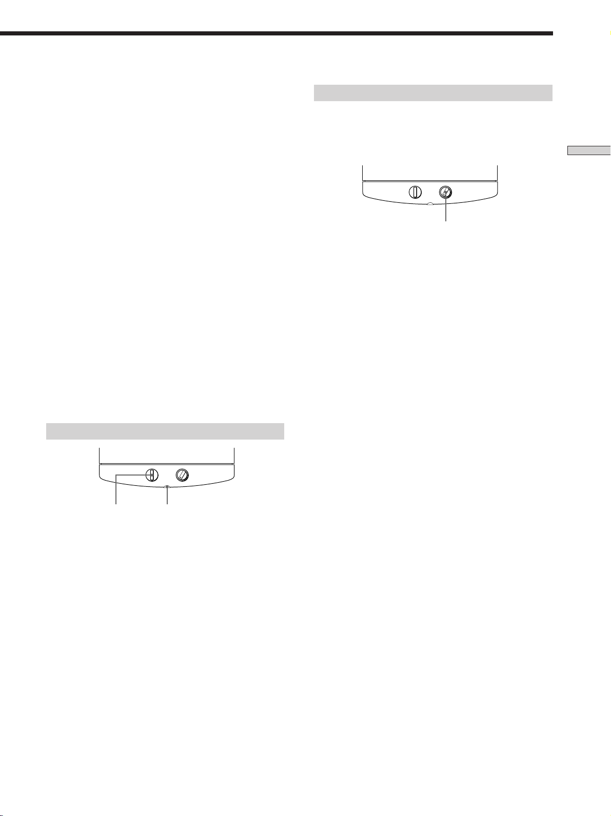
Listening to the sound
LEVEL
POWER
MIN MAX
POWER
POWER indicator
First, turn down the volume on the amplifier. The volume
should be set to minimum before you begin playing the
programme source.
1 Turn on the amplifier and select the programme
source.
2 Press POWER on the subwoofer.
The POWER indicator on the subwoofer lights up in
green.
3 Play the programme source.
19
GB
Page 20
Before You Use Your Amplifier
Checking the connections
After connecting all of your components to the amplifier,
do the following to verify that the connections were made
correctly.
Hooking Up and Setting Up the Speaker System
?/1 MASTER VOLUME
?/1
SURR LEVEL SET UP
Function buttons
VIDEO TV DVD AUX 5.1CH/SAT
+–
1 Press ?/1 to turn on the amplifier.
2 Press a function button to select a component
(program source) that you connected (e.g., VIDEO,
TV).
3 Turn on the component and start playing it.
4 Rotate MASTER VOLUME to turn up the volume.
MASTER VOLUME
R
–+
SOUND FIELD MODE
There is no sound no matter which component is
selected.
, Check that both the amplifier and all components
are turned on.
, Check that the volume level on the display is not
set to VOL MIN by turning the MASTER
VOLUME.
, Check that all speaker cords are connected
correctly.
, Press MUTING on the remote to turn off the
MUTING function.
There’s no sound from a specific component.
, Check that the component is connected correctly to
audio input jacks for that component.
, Check that the cord(s) used for the connection is
(are) fully inserted into the jacks on both the
amplifier and the component.
If you encounter a problem that is not included above, see
“Troubleshooting” on page 34.
If you do not obtain normal sound output after
performing this procedure, look for the reason in the
checklist on this page and take the appropriate measures
to correct the problem.
20
GB
Page 21

Location of
Parts and Basic
Operations
This chapter provides information
about the locations and functions of
the buttons and controls on the front
panel. It also explains basic
operations.
Front Panel Parts
Descriptions
Location of Parts and Basic Amplifier Operations
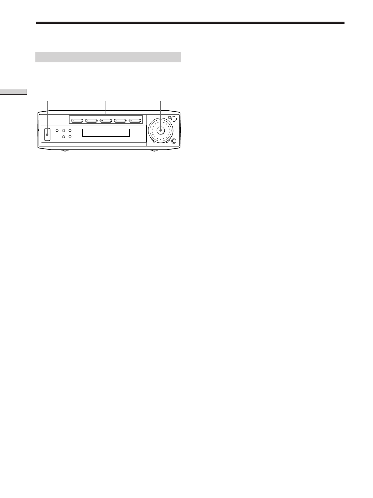
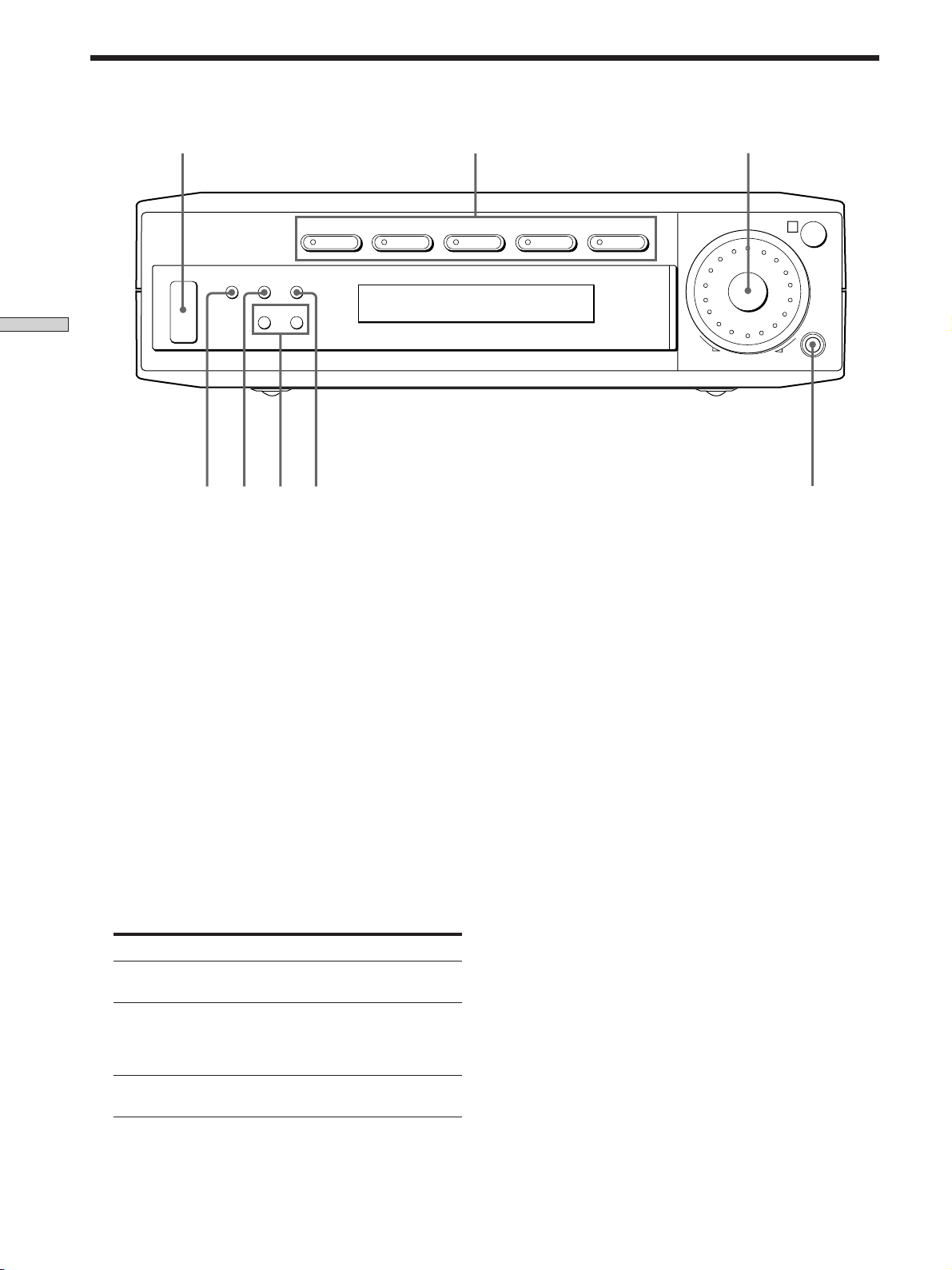
1 ?/1 switch
Press to turn the amplifier on and off.
2 Function buttons
Press one of the buttons to select the component you
want to use.
To select Press
VCR VIDEO
TV TV
DVD player DVD
An audio component AUX
DVD through AC-3 5.1 CH/SAT
decoder
After selecting the component, turn on the component
you selected and play the program source.
• After selecting VCR or DVD player, turn on the TV and set
the TV’s video input to match the component you selected.
21
GB
Page 22
Front Panel Parts Descriptions
1
VIDEO TV DVD AUX 5.1CH/SAT
?/1
SURR LEVEL SET UP
+–
Location of Parts and Basic Amplifier Operations
45 67
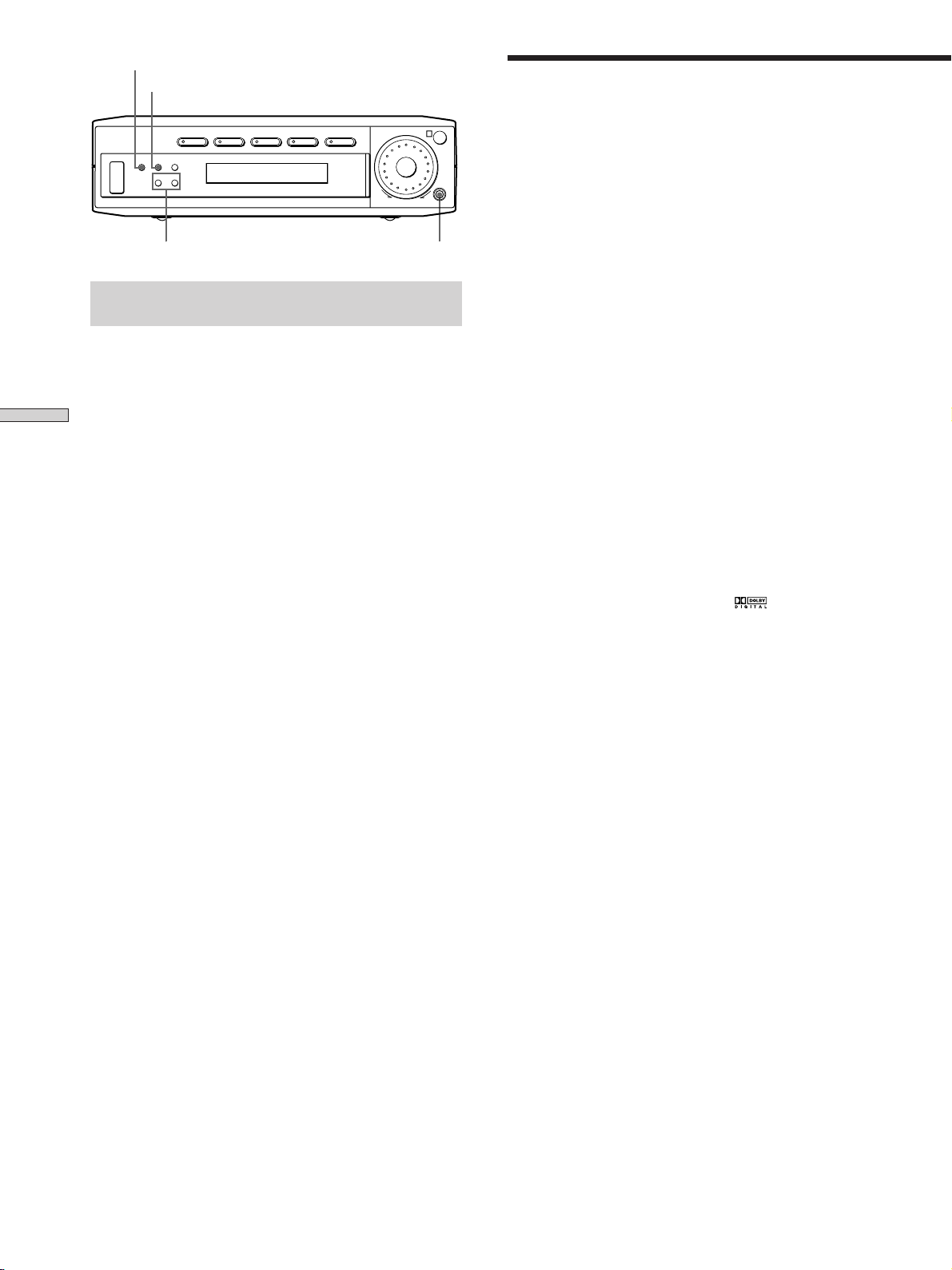
3 MASTER VOLUME control
After turning on the component you selected, rotate to
adjust the volume.
23
MASTER VOLUME
R
+
SOUND FIELD MODE
8
7 +/– buttons
Press to adjust the selected speaker level and surround
parameters (etc.).
4 SURR button
Press repeatedly to activate the surround parameters
(page 29) and to adjust the various surround
parameters (effect level, wall type, etc.). You can then
make various settings using the +/– buttons (7).
5 LEVEL button
Press repeatedly to activate the speaker level
parameters (page 30) and to adjust the various speaker
level parameters (front balance, rear balance, etc.). You
can then make various settings using the +/– buttons
(7).
6 SET UP button
Press repeatedly to activate the setup mode and to
select any of the following indications. You can then
make various settings using the +/– buttons (7).
When you select You can
Speaker type Specify the type of speakers.
(page 15)
Speaker setup Specify the front, center, rear
speaker sizes, the rear speaker
position, and whether or not you
are using a sub woofer. (page 15)
Speaker Distance Specify the front, center, and rear
speaker distances. (page 17)
8 SOUND FIELD MODE
Press repeatedly to activate the sound field selection
mode and to select the sound field you want (page 24).
22
GB
Page 23

Enjoying
Surround
Sound
This chapter describes how to set up
the amplifier to enjoy surround
sound. You can enjoy multi channel
surround when playing back software
encoded with Dolby Digital or DTS.
You can take advantage of surround sound simply by
selecting one of the amplifier’s pre-programed sound
modes. They bring the exciting and powerful sound of
movie theaters and concert halls into your home. You can
also customize the sound modes to obtain the sound you
desire by changing the various surround parameters.
The amplifier contains a variety of different sound modes.
The cinema sound modes are designed for use when
playing back movie software (DVD, LD, etc.) encoded
with multi channel surround sound or Dolby Pro Logic.
In addition to decoding the surround sound, some of
these modes also provide sound effects commonly found
in movie theaters.
The virtual sound modes contain compelling applications
of the Sony Digital Cinema Sound digital signal
processing technology. They shift the sound away from
the actual speaker locations to simulate the presence of
several “virtual” speakers.
The music (etc.) sound modes are designed for use with
standard audio sources and TV broadcasts. They add
reverberation to the source signal to make you feel as if
you were in a concert hall or stadium (etc.). Use these
sound modes with two-channel sources like CD and
stereo broadcasts of sports programs or musical concerts.
For more information about the sound modes, see pages
25 - 26.
Enjoying Surround Sound
A.F.D.
The “Auto Format Decoding” sound mode presents the
sound exactly as it was encoded, without adding any
reverberation (etc.).
To fully enjoy surround sound, you must register the
number and location of your speakers. See “MultiChannel Surround setup” starting on page 15 to set the
speaker parameters before enjoying surround sound.
23
GB
Page 24
SURR
LEVEL
Selecting a Sound Field
Brief descriptions of buttons used to
enjoy surround sound
LEVEL button: Press to customize the level parameters.
SURR button: Press to customize the surround
Enjoying Surround Sound
parameters in the current sound field.
+/– buttons: Use to adjust parameters and select sound
fields (etc.).
SOUND FIELD MODE button: Press to activate the sound
field selection mode.
?/1
SURR LEVEL SET UP
+/– buttons
VIDEO TV DVD AUX 5.1CH/SAT
+–
MASTER VOLUME
R
–+
SOUND FIELD MODE
SOUND FIELD MODE
You can enjoy surround sound simply by selecting one of
the pre-programed sound fields according to the program
you want to listen to.
1 Press SOUND FIELD MODE.
The current sound field is indicated in the display.
2 Press SOUND FIELD MODE repeatedly to select the
sound field you want.
See the table starting on page 25 for information on
each sound field.
To turn the sound field off
Press SOUND FIELD MODE repeatedly to select A.F.D or
2 CH.
z
The amplifier memorizes the last sound field selected for
each program source (Sound Field Link)
Whenever you select a program source, the sound field that was
last applied is automatically applied again. For example, if you
listen to CD with HALL as the sound field, change to a different
program source, then return to CD, HALL will be applied again.
z
You can identify Dolby Surround-encoded software by
looking at the packaging
Dolby Digital discs are labeled with the logo, and Dolby
Surround encoded programs are labeled with the A
logo.
24
GB
Page 25
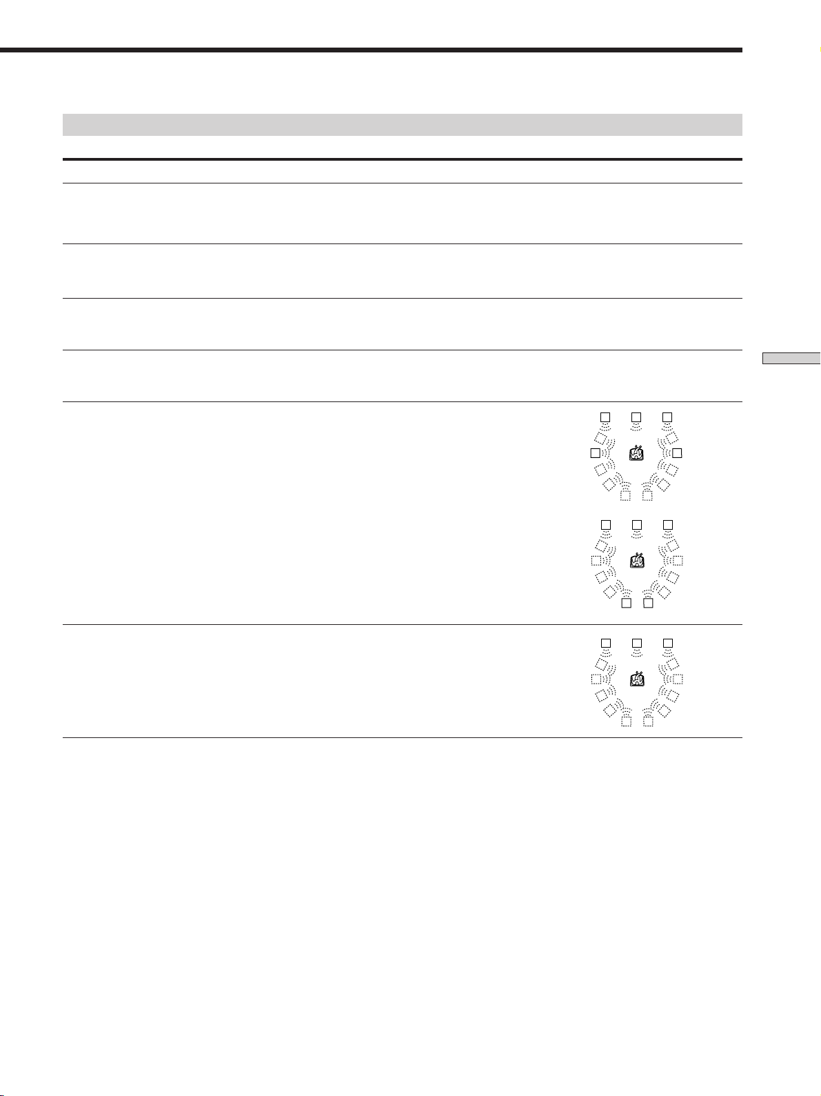
Sound field information
Sound field Effect Notes
NORM.SURR.
(NORMAL SURROUND)
Software with multi channel surround audio signals is
played according to the way it was recorded.
Software with two channel audio signals, is decoded
with Dolby Pro Logic to create surround effects.
CINEMA A
(CINEMA STUDIO A)
CINEMA B
(CINEMA STUDIO B)
CINEMA C
(CINEMA STUDIO C)
V.M.DIMENS.*
(VIRTUAL MULTI
DIMENSION)
V.SEMI M.D.*
(VIRTUAL SEMI-MULTI
DIMENSION)
Reproduces the sound characteristics of the Sony
Pictures Entertainment “Cary Grant Theater” cinema
production studio.
Reproduces the sound characteristics of the Sony
Pictures Entertainment “Kim Novak Theater” cinema
production studio.
Reproduces the sound characteristics of the Sony
Pictures Entertainment scoring stage.
Uses 3D sound imaging to create an array of virtual rear
speakers positioned higher than the listener from a
single pair of actual rear speakers. This mode creates
four sets of virtual speakers surrounding the listener at
approximately a 30° angle of elevation.
Uses 3D sound imaging to create virtual rear speakers
from the sound of the front speakers without using
actual rear speakers. This mode creates five sets of
virtual speakers surrounding the listener at a 30° angle
of elevation.
This is a standard mode, great for
watching most type of movie.
This mode is ideal for watching sciencefiction or action movies with lots of sound
effects.
This mode is ideal for watching musicals
or classic films where music is featured in
the soundtrack.
LCR
SIDE**
LS
LCR
BEHIND**
LS
LCR
LS
RSLS
RS
RSLS
RSLS
RS
** See
RSLS
RSLS
page 16
RSLS
RS
Enjoying Surround Sound
* “VIRTUAL” sound field: Sound field with virtual speakers.
25
GB
Page 26
Selecting a Sound Field
Sound field information
Sound field Effect Notes
HALL
Reproduces the acoustics of a rectangular concert hall.
Ideal for soft acoustic sounds.
JAZZ
(JAZZ CLUB)
LIVE
(LIVE HOUSE)
GAME
Notes
• The effects provided by the virtual speakers may cause increased noise in the playback signal.
Enjoying Surround Sound
• When listening to sound fields that employ the virtual speakers, you will not be able to hear any sound coming directly from the rear
speakers.
Use the buttons on the remote to operate the following modes
AUTO FORMAT DECODING
(Press the A.F.D. button)
2 CHANNEL
(Press the 2CH/OFF button)
Reproduces the acoustics of a jazz club.
Reproduces the acoustics of a 300-seat live house.
Obtains maximum audio impact from video game
software.
Automatically detects the type of audio signal being
input (Dolby Digital, Dolby Pro Logic, or standard two
channel stereo) and performs the proper decoding if
necessary. This mode presents the sound as it was
recorded/encoded, without adding any effects.
Outputs the sound from the front left and right
speakers only. Standard two channel (stereo) sources
completely bypass the sound field processing. Multi
channel surround formats are downmixed to two
channels.
Great for rock or pop music.
Be sure to set the game machine to stereo
mode when using game software with
stereo sound capabilities.
The ”Auto Format Decoding” sound mode
presents the sound exactly as it was
encoded, without adding any
reverberation (etc.).
This allows you to play any source using
only the front left and right speakers.
Note
To listen to two channel (stereo) sources using the front left and right speakers and a sub woofer, use the AUTO FORMAT DECODING
mode.
26
GB
Page 27
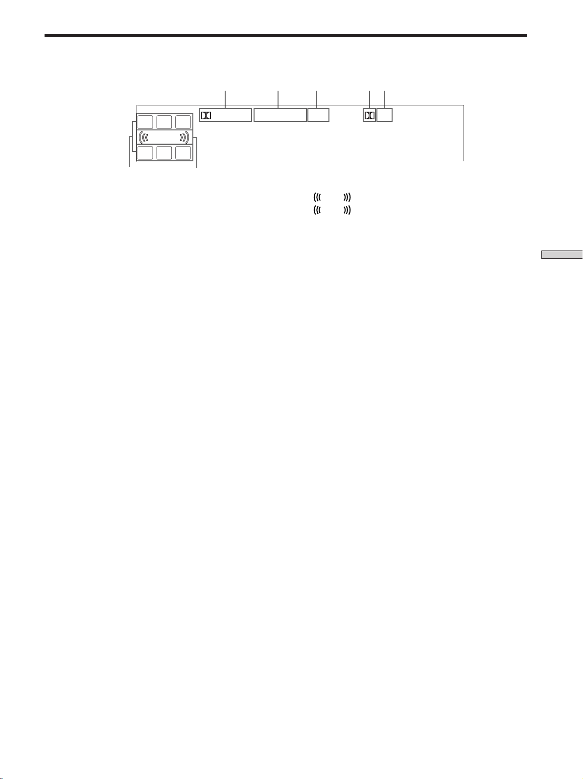
Understanding the Multi-Channel Surround Displays
1 4 5
L
CR
DIGITAL PRO LOGIC OPT
LFE
LS S RS
6
1 ; DIGITAL
This indicator lights up when a sound field other than
2 CHANNEL is selected and the unit is decoding
signals recorded in the Dolby Digital (AC-3) format.*
* However, this indicator does not light when the recording format
is 2/0 or 2/0 Pro logic.
2 PRO LOGIC
Lights up when the amplifier applies Pro Logic
processing to two channel signals in order to output
the center and surround channel signals.**
** However, this indicator does not light if the center and rear
speakers are set to “NO”, and the A.F.D. or NORMAL
SURROUND sound fields are selected.
3 OPT
Lights up when the source signal is a digital signal
being input through the OPT terminal.
7
2 3
7
contains the LFE (Low Frequency Effect) channel and
when the sound of the LFE channel signal is actually
being reproduced.
dts
L F E
L F E
will light up when the disc being played
Enjoying Surround Sound
4 ;
Lights up when Dolby Digital (AC-3) signals are input
through the OPT terminal.
5 dts
Lights up when DTS signals are input through the
OPT terminal.
6 Playback channel indicators
The letters light up to indicate the channels being
played back.
L: Front Left R: Front Right
C: Center (monaural) LS: Left Surround
RS: Right Surround
S: Surround (monaural or the rear components
obtained by Pro Logic processing)
The boxes around the letters light up to indicate the
speakers used to playback the channels.
See the next page for details regarding the playback
channel indicators.
27
GB
Page 28
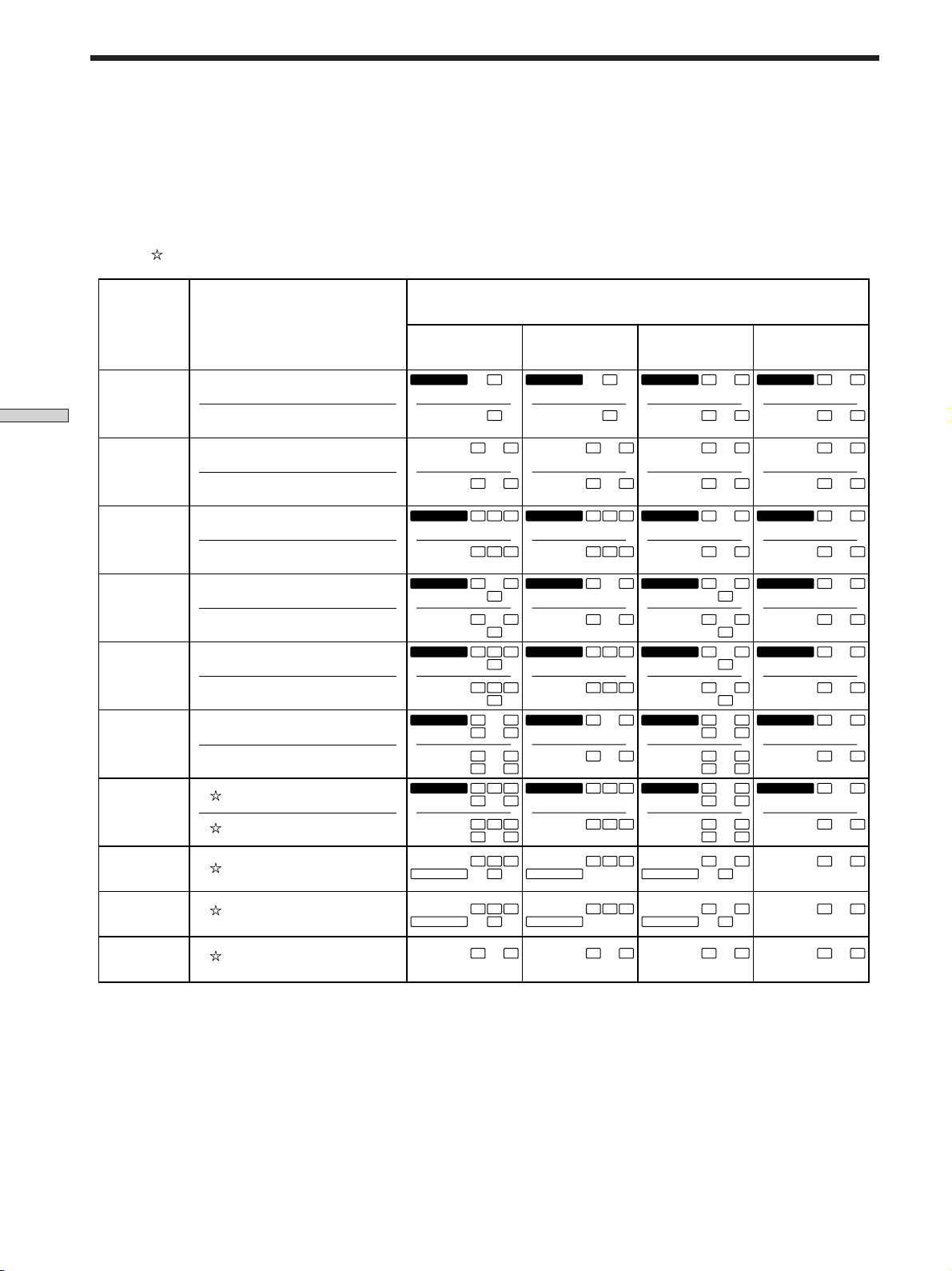
Understanding the Multi-Channel Surround Displays
Source sound displays
The letters (L, C, R, etc.) indicate the source sound. The box around the letters varies to show how the amplifier downmixes
the source sound (based on the speakers settings). When using music sound modes such as HALL or JAZZ CLUB, the
amplifier adds reverberation based on the source sound.
The following table shows how the indicators light up when using AUTO FORMAT DECODING mode.
Although the table below shows almost all of the configurations available from multi channel surround signals, the ones
marked “
” are the most common.
Recording
(Front/Rear)
Enjoying Surround Sound
Format
1/0
2/0*
3/0
2/1
3/1
2/2
3/2
2/0**
Input Channel Display
DOLBY DIGITAL [1/0]
DTS [1/0]
DOLBY DIGITAL [2/0]
DTS [2/0]
DOLBY DIGITAL [3/0]
DTS [3/0]
DOLBY DIGITAL [2/1]
DTS [2/1]
DOLBY DIGITAL [3/1]
DTS [3/1]
DOLBY DIGITAL [2/2]
DTS [2/2]
DOLBY DIGITAL [3/2]
DTS [3/2]
DOLBY DIGITAL [2/0]
All speakers
present
DIGITALaC
dts
dts
DIGITALaL C R
dts
DIGITALaLSR
dts
DIGITALaL CSR
dts
DIGITALaLLSR
dts
DIGITALaLLSC R
dts
PRO LOGIC
Source sound and Output Channel Display
Rear speakers
absent
DIGITALaC
C
dts
L R L R L R L R
L R L R L R
L C R
LSR
L CSR
LLSR
LLSC R
L CSR
RS
RS
RS
RS
dts
dts
dts
dts
dts
dts
PRO LOGIC
DIGITALaL C R
L C R
DIGITALaL
L
DIGITALaL CSR
L CSR
DIGITALaLLSR
LLSR
DIGITALaLLSC R
LLSC R
L CSR
C
R
S
R
S
RS
RS
RS
RS
Center speaker
absent
DIGITALaC
dts
dts
DIGITALaL CR
dts
DIGITALaLSR
dts
DIGITALaL CSR
dts
DIGITALaLLSR
dts
DIGITALaLLSCR
dts
PRO LOGIC
C
L CR
LSR
L CSR
LLSR
LLSCR
L CSR
Rear/center
speakers absent
DIGITALaC
dts
dts
DIGITALaL CR
dts
DIGITALaL
dts
DIGITALaL CSR
dts
DIGITALaLLSR
RS
dts
RS
DIGITALaLLSCR
RS
dts
RS
PRO LOGIC
C
L R
L CR
S
L
S
L CSR
LLSR
LLSCR
L CSR
R
R
RS
RS
RS
RS
DOLBY PROLOGIC
PCM XX kHz***
PRO LOGIC
L CSR
L R L R L R L R
PRO LOGIC
L CSR
PRO LOGIC
L CSR
PRO LOGIC
* Signals with Dolby surround encoded flag OFF
**Signals with Dolby surround encoded flag ON
*** The sampling rate is displayed.
Notes
• The amplifier performs Pro Logic decoding and the display conforms to 2/0** when using the following movie sound modes with
2/0* or STEREO PCM format signals. (CINEMA A, B, C, V.M.DIMENS., and V.SEMI M.D.)
• When using music sound modes such as HALL or JAZZ CLUB with standard audio formats e.g., PCM, the amplifier creates rear
signals from the front L and R signals. In this case, sound is output from the rear speakers, but output channel indicators for the rear
speakers do not light.
GB
28
L CSR
Page 29

Customizing Sound Fields
By adjusting the surround parameters, you can customize
the sound fields to suit your particular listening situation.
Once you customize a sound field, the changes are stored
in memory indefinitely (unless the amplifier is unplugged
for about two weeks). You can change a customized
sound field any time by making new adjustments to the
parameters.
See the table on page 31 for the parameters available in
each sound field.
To get the most from multi channel
surround sound
Position your speakers and do the procedures described
in “Multi Channel Surround Setup” starting on page 15
before you customize a sound field.
Adjusting the surround parameters
The SURR menu contains parameters that let you
customize various aspects of the current sound field. The
settings available in this menu are stored individually for
each sound field.
Wall type (WALL)
Initial setting : midpoint
When sound is reflected off soft material, such as a
curtain, the high frequency elements are reduced. A hard
wall is highly reflective and does not significantly affect
the frequency response of the reflected sound. This
parameter lets you control the level of the high
frequencies to alter the sonic character of your listening
environment by simulating a softer (S) or harder (H) wall.
The midpoint designates a neutral wall (made of wood).
Reverberation (REVB.)
Initial setting : midpoint
Before sound reaches our ears, it is reflected
(reverberated) many times between the left and right
walls, ceiling, and floor. In a large room, sound takes more
time to bounce from one surface to another than in a
smaller room. This parameter lets you control the spacing
of the early reflections to simulate a sonically larger (L) or
smaller (S) room.
• The reverberation can be adjusted from REVB. S. 1 ~
REVB. S. 8 (short) to REVB. L. 1 ~ REVB. L. 8 (long) in
17 steps.
• The midpoint (REVB. MID) designates a standard room
with no adjustment.
Enjoying Surround Sound
1 Start playing a program source encoded with multi
channel surround sound.
2 Press SURR repeatedly to select the parameter you
want to adjust.
3 Press the +/– buttons to select the setting you
want.
The setting is stored automatically.
Effect level (EFFECT)
Initial setting : (depends on sound mode)
This parameter lets you adjust the “presence” of the
current surround effect.
29
GB
Page 30

Customizing Sound Fields
Adjusting the level parameters
The LEVEL menu contains parameters that let you adjust
the balance and speaker volumes of each speaker. The
settings available in this menu are applied to all sound
fields.
1 Start playing a program source encoded with multi
2 Press LEVEL repeatedly to select the parameter you
3 Press the +/– buttons to select the setting you
Enjoying Surround Sound
*Front balance (
Initial setting : balance
Lets you adjust the balance between the front left and
right speakers.
• The balance can be adjusted ±8 steps.
• These settings can also be adjusted using the supplied
remote. See “Adjusting the speaker volume” (page 18).
channel surround sound.
want to adjust.
want.
The setting is stored automatically.
L R
)
*Sub woofer level (S.W. xx)
Initial setting : 0 dB
Lets you adjust the level of the sub woofer.
• The level can be adjusted in 1 dB steps from –10 dB to
+6 dB.
* The parameters can be adjusted separately for 5.1 CH/SAT.
*Rear balance (
Initial setting : balance
Lets you adjust the balance between the rear left and right
speakers.
• The balance can be adjusted ±8 steps.
• These settings can also be adjusted using the supplied
remote. See “Adjusting the speaker volume” (page 18).
*Rear level (REAR)
Initial setting : 0 dB
Lets you adjust level of the rear (left and right) speakers.
• The level can be adjusted in 1 dB steps from –10 dB to
+6 dB.
• These settings can also be adjusted directly using the
supplied remote. See “Adjusting the speaker volume”
(page 18).
*Center level (CTR)
Initial setting : 0 dB
Lets you adjust the level of the center speaker.
• The level can be adjusted in 1 dB steps from –10 dB to
+6 dB.
LS RS
)
30
GB
Page 31

Resetting customized sound fields to the
factory settings
1 If the power is on, press ?/1 to turn off the power.
2 Hold down SOUND FIELD MODE and press ?/1.
“SURR. CLR.” appears in the display and all sound
fields are reset at once.
Adjustable parameters for each sound field
EFFECT WALL REVERB FRONT REAR REAR CENTER
LEVEL TYPE TIME BAL. BAL. LEVEL LEVEL
2CH rr
A.F.D. rr rrr
NORMAL SURROUND rr rrr
CINEMA STUDIO A rrrrrr
CINEMA STUDIO B rrrrrr
CINEMA STUDIO C rrrrrr
V. MULTI DIMENSION rr rrr
V. SEMI–M. DIMENSION rrr
HALL rrrr r rrr
JAZZ CLUB rrrr r rrr
LIVE HOUSE rrrr r rrr
GAME rrrr r rrr
SUB WOOFER
LEVEL
Enjoying Surround Sound
5.1CH/SAT rr rrr
GB
31
Page 32

Other
Operations
SLEEP
SYSTEM
STANDBY
5.1 CH
ENTER/EXECUTIVE
(
p
P
? / 1
DVD
AUX
EXIT/RETURN
)
ANT
TV/VTR
SLEEPAV? / 1
TV VIDEO
MENU DISPLAY
TITLE
0
TV/
VIDEO
TV VOL
TV CH
VTR CH
A.F.D. SOUND2CH/OFF
Brief descriptions of buttons that appear
in this chapter
SLEEP button: Press to set the amplifier off automatically
at a specified time.
32
GB
Page 33

Using the Sleep Timer
You can set the amplifier to turn off automatically at a
specified time.
Press SLEEP on the remote while the power is on.
Each time you press SLEEP, the time changes as shown
below.
n 2:00:00 n 1:30:00n 1:00:00 n 0:30:00 n OFF
The display dims after you have specified the time.
z
You can freely specify the time
First, press SLEEP on the remote, then specify the time you want
using the +/– buttons. The sleep time changes in 1 minute
intervals. You can specify up to 5 hours.
z
You can check the time remaining before the amplifier turns
off
Press SLEEP on the remote. The remaining time appears in the
display.
Other Operations
33
GB
Page 34

Additional
Troubleshooting
Information
If you experience any of the following difficulties while
using the amplifier, use this troubleshooting guide to help
you remedy the problem. Also, see “Checking the
connections” on page 20 to verify that the connections are
correct. Should any problem persist, consult your nearest
Sony dealer.
There’s no sound or only a very low-level sound
is heard.
, Check that the speakers and components are
connected securely.
, Make sure that you’ve selected the correct
component on the amplifier.
, Press MUTING on the remote if MUTING appears
on the display.
, The protective device on the amplifier has been
activated because of a short circuit. Turn off the
amplifier, eliminate the short-circuit problem and
turn on the power again.
The left and right sounds are unbalanced or
reversed.
, Check that the speakers and components are
connected correctly and securely.
, Adjust front balance parameter in the LEVEL
menu.
Severe hum or noise is heard.
, Check that the speakers and components are
connected securely.
, Check that the connecting cords are away from a
transformer or motor, and at least 3 meters (10 feet)
away from fluorescent light.
, Move your TV away from the audio components.
, The plugs and jacks are dirty. Wipe them with a
cloth slightly moistened with alcohol.
No sound is heard from the center speaker.
, Make sure the sound field function is on (press
SOUND FIELD MODE).
, Select a sound field containing the word “cinema”
or “virtual” (see pages 24 - 26).
, Adjust the speaker volume (see page 18).
, Select MICRO SP. from the SET UP menu (see
page 15).
34
GB
Page 35

No sound or only a very low-level sound is heard
from the rear speakers.
, Make sure the sound field function is on (press
SOUND FIELD MODE).
, Select a sound field containing the word “cinema”
or “virtual” (see pages 24 - 26).
, Adjust the speaker volume (see page 18).
, Select MICRO SP. from the SET UP menu (see
page 15).
No sound is heard from the sub woofer.
, Select MICRO SP. from the SET UP menu (see
page 15).
The surround effect cannot be obtained.
, Make sure the sound field function is on (press
SOUND FIELD MODE).
The remote does not function.
, Point the remote at the remote sensor g on the
amplifier.
, Remove any obstacles in the path between the
remote and the amplifier.
, Replace both batteries in the remote with new
ones, if they are weak.
, Make sure you select the correct function on the
remote.
, If the remote is set to operate the TV only, use the
remote to select a source or component other than
TV before operating the amplifier or other
component.
Reference sections for clearing the
amplifier’ s memory
To clear See
All memorized settings page 14
Customized sound fields page 31
Additional Information
35
GB
Page 36

Specifications
Amplifier section
POWER OUTPUT
Rated Power Output at Stereo mode
(8 ohms 1 kHz, THD
0.7%)
25 W + 25 W
Reference Power Output
(8 ohms 1 kHz, THD
0.7%)
Front: 25 W + 25 W
Center: 25 W
Rear: 25 W + 25 W
Frequency response
DVD, TV, VIDEO, AUX:
20 Hz - 20 kHz + 0.5/
–2 dB
Inputs (Analog)
5.1CH/SAT, TV, VIDEO:
Sensitivity: 250 mV
Impedance: 50
kilohms
a)
S/N
: 96 dB (A, 250
mVb))
Inputs (Digital)
DVD, AUX (optical):
Sensitivity: –
Impedance: –
S/N: 100 dB (A, 20
kHz LPF)
Outputs SUB WOOFER:
Voltage: 2 V
Impedance: 1
kilohms
General
Power requirements
220-230 V AC, 50/60 Hz
Power consumption
120 W
Dimensions 296.5 × 215 × 60 mm
including projecting
parts and controls
Mass (Approx.)
4.2 kg
a) INPUT SHORT
Additional Information
b) Weighted network, input level
36
GB
Page 37

Speaker Section
SS-MS215 Front, center and rear
speakers
Speaker system
Full range, magnetically
shielded
Speaker units
5 cm cone type
Enclosure type
Bass reflex
Rated impedance
8 ohms
Power handling capacity (Maximum
input power)
60 watts
SA-WMS215 subwoofer
System Speaker system
Active subwoofer,
magnetically shielded
Speaker unit Woofer: 16 cm cone type
Enclosure type Acoustically Loaded
Bass Reflex
Continuous RMS power output (8 ohms,
20 - 250 Hz
50 W
Reproduction frequency range
32 Hz - 250 Hz
High frequency cut-off frequency
250 Hz
General
Power requirements
220 - 230 V AC, 50/60 Hz
Power consumptions
45 W
Dimensions (w/h/d)
Approx. 240 x 285 x
355mm including
front panel
Mass Approx. 8 kg
Supplied accessories
See page 4.
Design and specifications are subject to
change without notice.
Sensitivity level
84 dB (1 W, 1m)
Frequency range
150 Hz - 20, 000 Hz
Dimensions (w/h/d)
Approx. 76 x 100 x
86mm including
front grille
Mass Approx. 425 g
Input
LINE IN (input pin jack)
Specification indicated are measured at
230 V AC, 50 Hz.
Additional Information
37
GB
Page 38

Glossary
Surround sound
Sound that consists of three elements:
direct sound, early reflected sound
(early reflections) and reverberative
sound (reverberation). The acoustics
of the surrounding space affect the
way these three sound elements are
heard. Surround sound combines
these sound elements in such a way
that you actually can sense the size of
the venue, as well as its type.
• Types of sound
Early reflections
Direct sound
• Transition of sound from rear speakers
Direct sound
Level
Early
reflections
Additional Information
Early reflection time
Reverberation
Reverberation
Time
Dolby Digital (AC-3)
This sound format for movie theaters
is more advanced than Dolby Pro
Logic Surround. In this format, the
rear speakers output stereo sound
with an expanded frequency range
and a sub woofer channel for deep
bass is independently provided. This
format is also called “5.1” because the
sub woofer channel is counted as 0.1
channel (since it functions only when
a deep bass effect is needed). All six
channels in this format are recorded
separately to realize superior channel
separation. Furthermore, since all the
signals are processed digitally, less
signal degradation occurs. The name
“AC-3” comes from the fact that it is
the third audio coding method to be
developed by the Dolby Laboratories
Licensing Corporation.
Digital Cinema Sound
This is the generic name of the
surround sound produced by digital
signal processing technology
developed by Sony. Unlike previous
surround sound fields mainly
directed at the reproduction of music,
Digital Cinema Sound is designed
specifically for the enjoyment of
movies.
Dolby Pro Logic Surround
As one method of decoding Dolby
Surround, Dolby Pro Logic Surround
produces four channels from twochannel sound. Compared with the
former Dolby Surround system,
Dolby Pro Logic Surround reproduces
left-to-right panning more naturally
and localizes sounds more precisely.
To take full advantage of Dolby Pro
Logic Surround, you should have one
pair of rear speakers and a center
speaker. The rear speakers output
monaural sound.
GB
38
Page 39

Settings Using SURR, LEVEL, and SET UP buttons
You can make various settings using the LEVEL, SURR, SET UP buttons, and + /– buttons. The table below shows each of
the settings that these buttons can make.
Press
SURR button
LEVEL button
SET UP
Press button repeatedly to
Press + /– button to select See page
select
EFFECT LEVEL depends on sound mode (in 16 steps)
WALL TYPE between –8 to +8 (in 1 increment steps)
REVERBERATION TIME between –8 to +8 (in 1 increment steps)
FRONT BALANCE
REAR BALANCE
REAR LEVEL
CENTER LEVEL
SUB WOOFER LEVEL
* Speaker type NORM. SP. or MICRO SP.
(FRONT) LARGE or SMALL
L R
C
(CENTER) LARGE, SMALL, or NO
LS RS
(REAR) LARGE, SMALL, or NO
REAR PL. PL. SIDE or PL. BEHD.
REAR HGT. HGT. LOW or HGT. HIGH
SUB WOOFER S.W. YES or S.W. NO
(FRONT) XX.X METER between 3 feet (1.0 meters) and 40 feet (12.0
L R
C
(CENTER) XX.X METER between FRONT and 5 feet (1.5 meters) (in 1 foot
LS RS
(REAR) XX.X METER between FRONT and 15 feet (4.5 meters) (in 1
between –8 to +8 (in 1 increment steps)
between –8 to +8 (in 1 increment steps)
between –10 dB to +6 dB (in 1 dB steps)
between –10 dB to +6 dB (in 1 dB steps)
between –10 dB to +6 dB (in 1 dB steps)
meters) (in 1 foot (0.1 meter) steps)
(0.1 meter) steps)
foot (0.1 meter) steps)
29
30
15
Additional Information
* When you press the SET UP button, you can select NORM. SP. (for normal speakers) or MICRO SP. (for Micro Satellite speakers).
(page 15)
39
GB
Page 40

Remote Button Description
For buttons not described on previous pages and buttons
with names different from the buttons on the main unit.
Remote Button Operations Function
m/M VCR/DVD/ Fast forward or rewinds.
./> DVD/CD/ Skips tracks.
X VCR/DVD/ Pauses play.
N VCR/DVD/ Starts play.
x VCR/DVD/ Stops play.
AV/ TV/VCR/ Turns on or off the
?/1 DVD/LDP power.
ENTER/ TV/VCR/ Confirm setting.
EXECUTE DVD
ANT TV/ VCR Selects outputs signal
VCR from the antena terminal:
MENU TV/VCR/ Display menu.
TITLE DVD Display current DVD
EXIT/ TV/DVD Exit from menu mode or
RETURN return to previous screen.
Additional Information
DISPLAY TV/DVD/ Selects information
>
>
> TV/VCR/ To move the cursor to the
< TV/VCR/ To move the cursor to the
CD/LDP
LDP
CD/LDP
CD/LDP
CD/LDP
TV signal or VCR
programme.
DVD programs.
title.
LDP displayed on the TV
screen.
TV/VCR/ To increase a value or
DVD move the cursor
upwards on the menu
screen such as VIDEO
CONTROL/ AUDIO
CONTROL/ SET UP/
LANGUAGE/ DEMO
TV/VCR/ To decrease the value or
DVD move the cursor
downwards on the menu
screen such as VIDEO
CONTROL/AUDIO
CONTROL/SET UP/
LANGUAGE/DEMO
DVD right side of the menu
screens.
DVD left side of the menu
screen.
Remote Button Operations Function
VTR CH VCR VCR channel selection.
+/–
TV CH TV TV channel selection.
+/–
TV VOL TV To adjust the TV volume.
+/–
* The menu control keys may not operate on certain Sony TVs.
40
GB
Page 41

Changing the factory setting of a function
button
If the factory settings of the SYSTEM CONTROL/
FUNCTION buttons don’t match your system
components, you can change them. The following table
shows the possibility of alternate function assignment for
each button.
MENU
control keys
SYSTEM
STANDBY
5.1 CH
ENTER/EXECUTIVE
? / 1
DVD
AUX
EXIT/RETURN
SLEEPAV? / 1
TV VIDEO
MENU DISPLAY
TITLE
SYSTEM
CONTROL/
FUNCTION
Button
VIDEO
DVD, AUX
Possible assignment
VTR1, VTR 2, VTR 3
DVD, LDP, CD
• Initial setting of VIDEO is VTR 3.
• Sony VCR’s are operated with a VTR 1, 2, or 3 setting
that corresponds to Beta, 8mm and VHS, respectively.
Resetting key table for function key VIDEO
VTR 1
VTR 2
VTR 3
CURSOR UP
ENTER/EXECUTE
CURSOR DOWN
Resetting key table for function key DVD, AUX
DVD
LD
CD
Note
EXIT/RETURN
DISPLAY
CURSOR RIGHT
There is no initial setting for AUX. You need to reset this key
according to the equipment connected to the AUX input jack.
(
)
p
0
TV/
VIDEO
VTR CH TV VOL
ANT
TV/VTR
P
TV CH
For example, if you connect a Sony LD player to the DVD
jacks, you can assign the DVD button to set the remote to
control the LD player.
1 Hold down the SYSTEM CONTROL/FUNCTION
button whose function you want to change (DVD, for
example).
2 Press the corresponding button of the component
you want to assign to the SYSTEM CONTROL/
FUNCTION button (DISPLAY, LD player, for
example).
Now you can use the DVD button to control your Sony
LD player.
To reset a button to its factory setting
Repeat the above procedure.
Additional Information
To reset all the function buttons to their factory setting
Press ?/1, A V ?/1 and MASTER VOL – at the same time.
41
GB
Page 42

Index
A
AC-3. See Dolby Digital (AC-3)
Adjusting
speaker volumes 18
surround parameters 29
B
Basic amplifier operations
21 - 22
Batteries 4
C
Changing
effect level 29
Checking the connections 20
Clearing amplifier’s memory 14
Connecting. See Hookups
Customizing sound fields 29
D
Demonstration mode 3
Dolby Digital (AC-3) 38
Dolby Pro Logic Surround 38
E, F, G
Effect level 29
Additional Information
H
Hookups
5.1CH/SAT 8
AC power cord 9
digital components 7
speaker system 11
video components 6
P, Q
Parameter 29, 30, 31
S
Selecting
component 21
sound field 24
Sleep timer 33
Sound field
adjustable parameters 31
customizing 29
pre-programmed 24 - 26
resetting 31
selecting 24
Speakers
adjusting speaker volume 18
connection 11
placement 15
Supplied accessories 4
Surround sound 15 - 18, 23 - 31
T
Troubleshooting 34
U, V, W, X, Y, Z
Unpacking 4
42
GB
Page 43

AVERTISSEMENT
Afin d’éviter tout risque
d’incendie ou
d’électrocution, éviter
d’exposer l’appareil à la
pluie ou à l’humidité.
Afin d’écarter tout risque
d’électrocution, garder le coffret fermé.
Ne confier l’entretien de l’appareil qu’à
un personnel qualifié.
Précautions
Sécurité
• Si un solide ou un liquide tombait dans
le coffret, débranchez l’amplificateur et
faites-le vérifier par un technicien
qualifié avant de le remettre en service.
Sources d’alimentation
• Avant de mettre l’amplificateur en
service, vérifiez que sa tension de
fonctionnement correspond à celle du
courant secteur local. La tension de
fonctionnement est indiquée sur la
plaquette signalétique située au bas de
l’amplificateur.
• L’amplificateur n’est pas déconnecté de
la source d’alimentation tant qu’il est
branché sur une prise murale (secteur),
même si vous le mettez hors tension.
• Si vous ne comptez pas utiliser
l’amplificateur pendant un certain
temps, débranchez-le de la prise murale.
Pour débrancher le cordon, tirez sur la
fiche et jamais sur le cordon proprement
dit.
• Si le cordon d’alimentation secteur doit
être remplacé, faites appel à un
professionnel uniquement.
• L’interrupteur d’alimentation se trouve
sur le panneau avant.
Installation
• N’installez pas l’amplificateur dans un
espace confiné, comme dans une
bibliothèque ou un meuble encastré.
• Installez l’amplificateur dans un endroit
bien ventilé pour éviter tout risque de
surchauffe interne et prolonger la durée
de vie des composants.
• N’installez pas l’amplificateur près
d’une source de chaleur, dans un endroit
en plein soleil, poussiéreux ou exposé à
des chocs mécaniques.
• Ne posez rien sur le coffret qui puisse
bloquer les orifices de ventilation et
provoquer un mauvais fonctionnement.
• N’installez pas les enceintes dans une
position inclinée.
• Ne laissez pas les enceintes dans un
endroit :
– Extrêmement chaud ou froid
– Poussiéreux ou sale
– Très humide
– Sujet à des vibrations
– Exposé à la lumière directe du soleil
Fonctionnement
• Avant de raccorder d’autres appareils,
mettez l’amplificateur hors tension et
débranchez-le.
• Ne poussez pas le système d’enceintes à
une puissance excédant la capacité
d’entrée maximum du système.
• Si la polarité des connexions de
l’enceinte n’est pas correcte, les tonalités
graves seront faibles et la position des
différents instruments pourra paraître
instable.
• Le contact de deux fils d’enceintes
dénudés au niveau des bornes de
l’enceinte peut provoquer un courtcircuit.
• La grille de l’enceinte ne peut pas être
retirée. Ne tentez pas de retirer la grille
de l’enceinte. Si vous essayez de la
retirer, vous risquez d’endommager
l’enceinte.
Si les couleurs des images d’un
téléviseur proches sont instables
Cette enceinte possède un blindage
magnétique afin de pouvoir être installée
près d’un téléviseur. Cependant, il est
possible que des irrégularités de couleurs
puissent toutefois être observées sur
certains téléviseurs.
Si des irrégularités de couleurs sont
observées...
p Eteignez le téléviseur, puis rallumez-
le après 15 ou 30 minutes.
Si des irrégularités de couleurs sont
toujours observées...
p Eloignez les enceintes du téléviseur.
Si un sifflement se produit
Repositionnez les enceintes ou baissez le
volume de l’amplificateur.
Nettoyage
• Nettoyez le coffret, le panneau et les
commandes avec un chiffon doux
légèrement imprégné d’une solution
détergente neutre. N’utilisez pas de
tampon abrasif, poudre à récurer ou
solvant, comme de l’alcool ou de la
benzine.
En cas de question ou de problème
concernant l’amplificateur, consultez
le revendeur Sony le plus proche.
FR
2
Page 44

Au sujet de ce manuel
Conventions
• Les instructions dans ce manuel décrivent les
commandes de l’amplificateur. Vous pouvez aussi
utiliser les touches de la télécommande qui ont le même
nom ou un nom similaire.
• L’icône suivante est utilisée dans ce mode d’emploi:
z Indique des conseils et suggestions pouvant faciliter
certaines opérations.
Cet l’amplificateur intègre les systèmes surround Dolby*
Digital et Pro Logic et DTS** Digital.
Fabriqué sous licence de Dolby Laboratories. “Dolby”, “AC-3”, “Pro
*
Logic” et le symbole double-D a sont des marques commerciales de
Dolby Laboratories.
Projet confidentiel non publié. © 1992-1997 Dolby Laboratories, Inc.
Tous droits réservés.
** Fabriqué sous licence de Digital Theater Systems, Inc. Brevet
enregistré sous le No. 5.451.942 aux Etats-Unis et brevets
enregistrés ou en cours d’homologation dans d’autres pays. “DTS” et
“DTS Digital Surround” sont des marques de Digital Theater
Systems, Inc. © 1996 Digital Theater Systems, Inc. Tous droits
réservés.
TABLE DES MATIÈRES
Raccordement des appareils 4
Déballage 4
Configuration de l’amplificateur 5
Raccordement d’appareils vidéo 6
Raccordement d’appareils numériques 7
Raccordements 5.1 CH/SAT 8
Autres raccordements 9
Raccordement et configuration du
système acoustique 10
Raccordement du système acoustique 11
Opérations de réglage initial 14
Configuration du surround multicanal 15
Avant la mise en service de l’amplificateur 20
Mode de démonstration
La démonstration des fonctions de l’appareil commence la
première fois que vous mettez l’appareil sous tension. Lorsque
la démonstration commence, le message suivant apparaît
dans la fenêtre d’affichage:
“NOW DEMONSTRATION MODE IF YOU FINISH
DEMONSTRATION PLEASE PRESS POWER KEY
WHILE THIS MESSAGE APPEARS IN THE DISPLAY
THANK YOU”
Pour annuler la démonstration
Appuyez sur ?/1 pour éteindre l’amplificateur pendant
l’affichage du message ci-dessus. A la prochaine mise sous
tension de l’amplificateur, la démonstration n’apparaîtra pas.
Pour voir la démonstration
Tenez SET UP enfoncée tout en appuyant sur ?/1 pour mettre
l’amplificateur sous tension.
Remarques
• L’activation de la démonstration supprime la mémoire de
l’amplificateur, Pour les détails sur ce qui est supprimé, voir
“Annulation de la mémoire de l’amplificateur” à la page 14.
• Aucun son n’est diffusé lorsque le mode de démonstration
est activé.
Nomenclature et opérations
élémentaires 21
Description des éléments du panneau avant 21
Utilisation du son surround 23
Sélection d’un champ sonore 24
Signification des diverses indications du surround
multicanal 27
Personnalisation des champs sonores 29
Autres opérations 32
Utilisation du temporisateur 33
Informations complémentaires 34
Guide de dépannage 34
Spécifications 36
Glossaire 38
Réglages à l’aide des touches SURR, LEVEL,
et SET UP 39
Nomenclature de la télécommande 40
Index 42
FR
FR
3
Page 45

Raccordement
Déballage
des appareils
Ce chapitre explique comment
raccorder divers appareils audio et
vidéo à l’amplificateur. Veuillez lire
les paragraphes concernant les
appareils que vous avez avant de les
raccorder à l’amplificateur.
Vérifiez si les accessoires suivants se trouvent dans l’emballage.
• Télécommande (1)
• Piles de format AA (R6) (2)
• Enceintes (5)
• Enceinte avant (2)
• Enceinte arrière (2)
• Enceinte centrale (1)
• Caisson de grave amplifié (1)
• Cordon de raccordement de l’enceinte, long (2)
• Cordon de raccordement de l’enceinte, court (3)
• Cordon de connexion monophonique (1 phono vers 1
phono) (1)
• Blocs (20)
• Vis (1)
• Support d’amplificateur (1)
Mise en place des piles dans la
télécommande
Insérez des piles R6 (format AA) en faisant correspondre les
bornes + et – avec le schéma dans le logement. Pour utiliser la
télécommande, dirigez-la vers le détecteur
}
g
de l’amplificateur.
]
}
]
z
Remplacement des piles
Dans des conditions d’utilisation normales, les piles durent environ 6
mois. Quand vous ne pouvez plus faire fonctionner l’amplificateur
avec la télécommande, remplacez toutes les piles par des neuves.
Remarques
• Ne laissez pas la télécommande dans un endroit extrêmement
chaud ou humide.
• N’insérez pas une pile neuve avec une pile usée.
• N’exposez pas le détecteur infrarouge aux rayons directs du
soleil ni à un éclairage puissant pour éviter tout problème de
fonctionnement.
• Si vous prévoyez de ne pas utiliser la télécommande pendant
un certain temps, enlevez les piles pour éviter tout dommage
dû à une fuite d’électrolyte et à la corrosion.
Avant de commencer
• Mettez tous les appareils hors tension avant d’effectuer
les liaisons.
• Ne raccordez les cordons d’alimentation secteur que
lorsque toutes les liaisons sont terminées.
• Enfoncez les fiches à fond dans les prises pour éviter
tout bourdonnement et bruit.
• Lors du raccordement d’un cordon audio, branchez les
fiches sur les prises de même couleur: blanc (audio,
gauche) à blanc et rouge (audio, droit) à rouge.
FR
4
Page 46

Configuration de l’amplificateur
Vous pouvez placer l’amplificateur à plat sur une surface
ou sur le support de l’amplificateur. Assurez-vous de ne
rien placer sur l’ amplificateur.
1 Tournez l’amplificateur sur son côté.
Assurez-vous de placer l’amplificateur en positionnant
la touche ?/1 (marche/arrêt) en bas.
R
SOUND FIELD MODE
MASTER VOLUME
–+
VIDEO TV DVD AUX 5.1CH/SAT
+–
SURR LEVEL SET UP
?/1
2 Placez le support de l’amplificateur sur
l’amplificateur.
Assurez-vous d’aligner le trou du support avec le trou
de l’amplificateur.
5 Placez le support de l’amplificateur sur une surface
plate.
Remarque
Vous pouvez préparer le cordon d’alimentation et les autres
câbles sur le support de l’amplificateur comme le montre
l’illustration ci-dessous.
Raccordement des appareils
3 Appuyez pour insérer le support sur l’amplificateur.
4 Insérez la vis et serrez-la.
FR
5
Page 47

Raccordement d’appareils vidéo
Raccordement des appareils
TV
OUTPUT
AUDIO OUT
RL
DVD
AUX
TV VIDEO FRONT
Cordons nécessaires
Cordons audio (non fournis)
Lorsque vous raccordez des appareils, veillez à insérer les fiches
dans les prises de même couleur.
Blanc (G)
Rouge (D)
OUTPUT
AUDIO OUT
REAR
WOOFER
CENTER
5.1CH/SAT
WOOFER
OUT
L
R
FRONT REAR
IMPEDANCE USE 8-16 Ω
SPEAKERS
CENTER
L
R
L
R
Blanc (G)
Rouge (D)
OUTPUT
Magnétoscope
Prises pour le raccordement des appareils
vidéo
Branchez Sur
un TV les prises TV
un magnétoscope les prises VIDEO
ç
AUDIO
OUT
ç
IN OUT
INPUT OUTPUT
AUDIO
IN
L
AUDIO
OUT
R
L
R
FR
6
Page 48

Raccordement d’appareils numériques
Raccordez les prises d’entrée numériques de votre lecteur
DVD et des composants audio (lecteur CD, platine MD,
etc.) aux prises d’entrée numériques de l’amplificateur
pour amener le son spatial multi-canal d’un film dans
votre foyer. Pour obtenir un son surround multicanal
parfait, cinq enceintes (deux enceintes avant, deux
enceintes arrière et une enceinte centrale) et un caisson de
grave sont indispensables.
Lecteur DVD
DVD
(etc.)
OUTPUT
DIGITAL
OPTICAL
CENTER
L
L
Lecteur CD,
platine MD, etc.
OUTPUT
DIGITAL
OPTICAL
WOOFER
CENTER
5.1CH/SAT
Cordons nécessaires
Cordons numériques optiques (non fournis)
Noir Noir
Remarque
Les prises d’entrée numériques optiques de l’amplificateur sont
compatibles avec les fréquences d’échantillonnage de 32 kHz,
44.1kHz, 48 kHz et 96 kHz.
IMPEDANCE USE 8-16 Ω
L
SPEAKERS
Raccordement des appareils
AUX
TV VIDEO FRONT
R
R
REAR
Remarque
Raccordez la prise vidéo de votre lecteur DVD à la prise
VIDEO IN de votre téléviseur TV.
WOOFER
OUT
R
FRONT REAR
FR
7
Page 49

Raccordements 5.1 CH/SAT
Raccordement des appareils
Bien que cet amplificateur contienne un décodeur
multicanal, il est aussi équipé de prises 5.1CH/SAT. Ces
liaisons vous permettent d’écouter des logiciels
multicanal codés dans d’autres formats que Dolby Digital
(AC-3) et DTS. Si votre lecteur DVD est équipé de prises
5.1CH OUTPUT, vous pourrez les relier directement à
l’amplificateur pour bénéficier du son traité par le
décodeur multicanal du lecteur DVD. Sinon, les prises
5.1CH/SAT peuvent servir au raccordement d’un
décodeur multicanal autonome.
Pour tirer le meilleur parti du son surround multicanal, il
est nécessaire de raccorder cinq enceintes (deux enceintes
avant, deux enceintes arrière et une enceinte centrale) et
un caisson de grave. Reportez-vous au mode d’emploi
fourni avec le lecteur DVD, le décodeur multicanal, etc.
pour les détails sur le raccordement à l’entrée 5.1 canaux.
Lecteur DVD
Décodeur multicanal, etc.
5.1CH OUTPUT
CENTER
REAR
FRONT
Cordons nécessaires
Cordons audio (non fournis)
Deux pour les prises 5.1CH/SAT FRONT et REAR
Blanc (G) Blanc (G)
Rouge (D) Rouge (D)
Cordons audio monophoniques (non fournis)
Deux pour les prises 5.1CH/SAT CENTER et WOOFER
Noir Noir
Remarque
Lors de l’utilisation des raccordements décrits ci-dessous, ajustez
le niveau de vos haut-parleurs d’environnement, du haut-parleur
central et du haut-parleur des graves du lecteur DVD ou du
décodeur multi-canal.
WOOFER
REAR
WOOFER
CENTER
5.1CH/SAT
WOOFER
OUT
L
R
FRONT REAR
IMPEDANCE USE 8-16 Ω
SPEAKERS
DVD
AUX
TV VIDEO FRONT
CENTER
L
R
L
R
Exemple de raccordement d’un lecteur DVD aux prises 5.1CH/SAT
5.1 CH/SAT
VIDEO TV DVD AUX 5.1CH/SAT
?/1
Lecteur DVD
SURR LEVEL SET UP
+–
Remarque
Voir page 11 pour les détails sur le raccordement du système acoustique.
MASTER VOLUME
R
–+
SOUND FIELD MODE
SPEAKERS
FRONT
SPEAKERS
REAR/CENTER
SUB WOOFER
Enceinte avant (G)
Enceinte avant (D)
Enceinte arrière (G)
Enceinte arrière (D)
Enceinte centrale
Caisson de grave
amplifié
FR
8
Page 50

Autres raccordements
WOOFER
5.1CH/SAT
REAR
DVD
AUX
TV VIDEO FRONT
CENTER
L
R
L
R
Raccordement du cordon d’alimentation
secteur
Avant de raccorder le cordon d’alimentation secteur de
l’amplificateur à une prise murale:
• Raccordez le système acoustique à l’amplificateur (voir
page 11).
CENTER
WOOFER
OUT
L
R
FRONT REAR
IMPEDANCE USE 8-16 Ω
SPEAKERS
Cordon d’alimentation secteur
A une prise murale
Raccordement des appareils
b
Raccordez le(s) cordon(s) d’alimentation secteur de l’autre
ou des autres appareils vidéo à une prise murale.
Remarque
Si vous laissez le cordon d’alimentation débranché pendant deux
semaines environ, toute la mémoire de l’amplificateur sera
effacée et la démonstration commencera.
FR
9
Page 51

Raccordement
SET UP
R
?/1
VIDEO TV DVD AUX 5.1CH/SAT
SURR LEVEL SET UP
+–
SOUND FIELD MODE
MASTER VOLUME
–+
et
configuration
du système
acoustique
Ce chapitre indique comment relier le
système acoustique à l’amplificateur,
positionner chaque enceinte et
configurer les enceintes pour obtenir
un véritable son surround multicanal.
Touches +/–
Brève description des touches et
commandes nécessaires à la configuration
du système acoustique
Touche SET UP: Appuyez sur cette touche pour accéder
au mode de réglage lors de la désignation du type
d’enceintes ou de la distance des enceintes.
Touches +/–: Servent à sélectionner des paramètres après
une pression sur la touche SET UP.
FR
10
Page 52

Raccordement du système acoustique
Cordons nécessaires
Cordon de raccordement de l’enceinte (fourni)
Une blanche pour le SPEAKERS FRONT LEFT
Une rouge pour le SPEAKERS FRONT RIGHT
Une verte pour le SPEAKERS CENTER
Une bleue pour le SPEAKERS REAR LEFT
Une jaune pour le SPEAKERS REAR RIGHT
Raccordement et configuration du système acoustique
(–)
(+)
Cordon de connexion monophonique (fourni)
Un pour un caisson de grave amplifié
Noir Noir
Prises de
haut-parleurs
Remarques
• Vérifiez que vous avez inséré les cordons de raccordement des
extrémités des prises des haut-parleurs en suivant la
description des couleurs affichée dans la partie supérieure de
l’amplificateur.
• La polarité de la prise des haut-parleurs est définie sur
l’amplificateur.
11
FR
Page 53

Raccordement du système acoustique
Enceinte avant (L)
}
Enceinte avant (R)
]
Raccordement et configuration du système acoustique
CENTER
DVD
L
R
AUX
TV VIDEO FRONT
L
R
REAR
}
}
WOOFER
CENTER
5.1CH/SAT
WOOFER
OUT
Enceinte arrière (L)
]
FRONT REAR
}
L
R
]
IMPEDANCE USE 8-16 Ω
SPEAKERS
Enceinte arrière (R)
]
INPUT
}
]
Enceinte centrale
Bornes pour le raccordement des
enceintes
Branchez Sur
les enceintes avant (8 ohms) les bornes SPEAKERS FRONT
les enceintes arrière (8 ohms) les bornes SPEAKERS REAR
l’enceinte centrale (8 ohms) les bornes SPEAKERS CENTER
le caisson de grave amplifié la prise WOOFER OUT
Caisson de grave
amplifié
Remarques sur le raccordement du
système acoustique
• Assurez-vous que les terminaux plus (+) et moins (–)
des haut-parleurs correspondent aux terminaux plus (+)
et moins (–) des prises des haut-parleurs.
• Assurez-vous que toutes les connexions sont fermes. Le
contact de deux fils d’enceintes dénudés au niveau des
terminaux de l’enceinte peut provoquer un courtcircuit.
Suggestion
La polarité de tous les fils rayés est plus (+) et ces fils devront être
raccordés aux terminaux plus (+) des haut-parleurs.
12
FR
Page 54

Pour éviter de court-circuiter les enceintes
Un court-circuit des enceintes peut endommager
l’amplificateur. Pour éviter cela, veillez à prendre les mesures
suivantes au moment du raccordement des enceintes.
Assurez-vous que les extrémités dénudées de
chaque cordon d’enceinte ne touchent aucune
autre borne d’enceinte ou l’extrémité dénudée
d’un autre cordon d’enceinte.
Exemples de branchement dangereux d’un
cordon d’enceinte
Le cordon d’enceinte dénudé touche une autre borne
d’enceinte.
Pour éviter d’endommager les hautparleurs
Assurez-vous que vous avez baissé le volume avant de
mettre l’amplificateur hors tension. Lorsque vous mettez
l’amplificateur sous tension, le volume reste au niveau sur
lequel il était réglé lorsque vous l’avez mis hors tension.
Raccordement et configuration du système acoustique
Les cordons dénudés sont en contact car une partie trop
importante de leur gaine a été enlevée.
Après le raccordement de tous les appareils, des
enceintes et du cordon d’alimentation, générez
un signal de test pour vérifier si toutes les
enceintes ont été raccordées correctement. Pour
les détails sur l’émission d’un signal de test, voir
page 18.
Si aucun son n’est fourni par une enceinte pendant
l’émission d’un signal de test ou si un signal de test est
émis par une enceinte différente de celle indiquée sur
l’amplificateur, il est possible que l’enceinte soit courtcircuitée. Dans ce cas, vérifiez de nouveau le
raccordement de l’enceinte.
13
FR
Page 55

Opérations de réglage initial
Après avoir effectué toutes les liaisons et mis
l’amplificateur sous tension pour la première fois, annulez
la mémoire. Ensuite, réglez la taille et la position des
enceintes, et effectuer les réglages nécessaires. Puis,
spécifiez les paramètres des enceintes (taille, position, etc.)
Raccordement et configuration du système acoustique
et effectuez toutes les opérations de réglage initial
nécessaires à la configuration du système acoustique.
Annulation de la mémoire de
l’amplificateur
Avant d’utiliser l’amplificateur pour la première fois, ou
quand vous souhaitez effacer la mémoire de
l’amplificateur, effectuez les opérations suivantes.
Si la démonstration apparaît lorsque l’amplificateur est
sous tension, cette opération est inutile.
?/1
VIDEO TV DVD AUX 5.1CH/SAT
?/1
SURR LEVEL SET UP
+–
MASTER VOLUME
R
–+
SOUND FIELD MODE
Réglage de l’amplificateur
Avant d’utiliser l’amplificateur pour la première fois,
réglez les paramètres suivants en fonction de votre
système à l’aide de la touche SET UP. Pour les détails sur
chaque réglage, voir la page entre parenthèses.
• Réglage de la taille des enceintes. (page 15)
• Réglage de la distance des enceintes. (page 17)
1 Mettez l’amplificateur hors tension.
2 Appuyez sur ?/1 pendant quatre secondes.
La fonction actuellement sélectionnée, puis le message
de démonstration apparaissent sur l’afficheur. Tous les
paramètres suivants sont réinitialisés ou effacés:
• Tous les paramètres de champs sonores sont
réinitialisés à leurs réglages d’usines.
• Tous les réglages effectués avec la touche SET UP
sont réinitialisés à leurs valeurs d’usine.
• Le champ sonore mémorisé pour chaque source
sonore est effacé.
14
FR
Page 56

Configuration du surround multicanal
Pour obtenir le meilleur son surround possible, toutes les
enceintes doivent être à égale distance de la position
d’écoute (A).
(Toutefois, l’ampli-tuner permet de rapprocher l’enceinte
centrale (B) de 1,5 mètre (5 pieds) au maximum et les
enceintes arrière (C) de 4,5 mètres (15 pieds) au
maximum de la position d’écoute.
Les enceintes avant peuvent être placées de 1 à 12 mètres
(3 à 40 pieds) de la position d’écoute (A).)
Vous pouvez placer les enceintes arrière derrière ou de
chaque côté de votre position d’écoute, selon la forme de
la pièce, etc.
Quand vous disposez les enceintes sur les côtés
B
A A
45°
CC
Spécification des paramètre des enceintes
Pour le modèle HT-K215, la taille de l’enceinte et la
sélection du caisson de basses ont été préréglées sur
MICRO SP. (haut parleur Micro Satellite) en fonction du
système d’enceinte fourni. Si vous changez de système
d’enceinte, choisissez NORM. SP. (haut parleur
traditionnel) pour modifier la taille de l’enceinte et la
sélection du caisson de basses. Lorsque vous choisissez
MICRO SP., la taille des haut-parleurs et la sélection des
graves est configurée comme suit :
Hauts parleurs
Avant
Central
Arrière
Caisson de basses
Si vous choisissez MICRO SP., cette configuration ne peut pas
être modifiée.
Paramètres
SMALL (Petit)
SMALL (Petit)
SMALL (Petit)
YES (Oui)
1 Appuyez sur ?/1 pour mettre l’amplificateur sous
tension.
Raccordement et configuration du système acoustique
90°
20°
Quand vous disposez les enceintes à l’arrière
B
A A
45°
CC
90°
20°
Remarque
L’enceinte centrale et les enceintes arrière ne doivent pas être plus
éloignées de la position d’écoute que les enceintes avant.
2 Appuyez plusieurs fois sur SET UP pour
sélectionner le paramètre que vous souhaitez
ajuster.
3 Appuyez sur +/– pour sélectionner le paramètre
voulu.
Le réglage est sauvegardé automatiquement.
4 Répétez les étapes 2 et 3 jusqu’à ce que tous les
paramètres suivants soient réglés.
La configuration de la taille des haut-parleurs suivante
s’applique au type NORM. SP.
p Taille des enceintes avant (L R)
Réglage initial : LARGE
• Si vous raccordez des enceintes avant de grande taille
qui restituent efficacement les basses fréquences,
sélectionnez “LARGE”. Normalement, sélectionnez
“LARGE”.
• Si le son présente de la distorsion, ou s’il vous semble
que les graves font défaut quand vous utilisez le son
surround multicanal, sélectionnez “SMALL” pour
activer le circuit de réaiguillage du grave. Les basses
fréquences de la voie avant seront restituées par le
caisson de grave.
• Si les enceintes avant sont réglées sur “SMALL”, les
enceintes centrale et arrière se régleront également sur
“SMALL” (si elles n’ont pas été réglées sur “NO”).
15
FR
Page 57

Configuration du surround multicanal
p Taille de l’enceinte centrale (C )
Réglage initial : LARGE
• Si vous raccordez une enceinte centrale de grande taille
qui reproduit efficacement les basses fréquences,
sélectionnez “LARGE”. Normalement, sélectionnez
Raccordement et configuration du système acoustique
“LARGE”. Cependant, si les enceintes avant sont
réglées sur “SMALL”, vous ne pourrez pas régler
l’enceinte centrale sur “LARGE”.
• Si le son présente de la distorsion, ou s’il vous semble
que les graves font défaut quand vous utilisez le son
surround multicanal, sélectionnez “SMALL” pour
activer le circuit de réaiguillage du grave. Les basses
fréquences de la voie centrale seront restituées par les
enceintes avant (si elles sont réglées sur “LARGE”) ou
par le caisson de grave.*
1
• Si vous ne raccordez pas d’enceinte centrale,
sélectionnez “NO”.
Le son de la voie centrale sera fourni par les enceintes
2
avant.*
p Taille des enceintes arrière (LS RS)
Réglage initial : LARGE
• Si vous raccordez des enceintes arrière de grande taille
qui reproduisent efficacement les basses fréquences,
sélectionnez “LARGE”. Normalement, sélectionnez
“LARGE”. Cependant, si les enceintes avant sont
réglées sur “SMALL”, vous ne pourrez pas régler les
enceintes arrière sur “LARGE”.
• Si le son présente de la distorsion, ou s’il vous semble
que les graves font défaut quand vous utilisez le son
surround multicanal, sélectionnez “SMALL” pour
activer le circuit de réaiguillage du grave. Les basses
fréquences de la voie arrière seront restituées par le
caisson de grave ou d’autres enceintes réglées sur
“LARGE”.
• Si vous ne raccordez pas d’enceintes arrière,
sélectionnez “NO”.*
z
*1~*3 correspondent aux modes Dolby Pro Logic suivants
*1 NORMAL
*2 PHANTOM
*3 3 STEREO
3
z
Au sujet de la taille des enceintes (LARGE et SMALL)
Les réglages LARGE et SMALL de chaque enceinte déterminent
si le processeur de son interne doit couper ou non le signal grave
d’une voie. Lorsque le grave d’une voie est coupé, le circuit de
réaiguillage du grave transmet les basses fréquences
correspondantes au caisson de grave ou à une autre enceinte
réglée sur “LARGE”.
Cependant, comme les sons de basses fréquences se caractérisent
en partie par leur directionnalité, il vaut mieux ne pas les couper.
Même lorsque vous utilisez des enceintes de petites dimensions,
vous pouvez sélectionner “LARGE” si vous voulez que ces
enceintes fournissent les basses fréquences. Si par contre, vous
utilisez des enceintes de grandes dimensions, mais ne voulez pas
qu’elles fournissent les basses fréquences, réglez-les sur
“SMALL”.
Si le niveau général du son est à votre avis trop faible, réglez
toutes les enceintes sur “LARGE”.
p Position des enceintes arrière (REAR PL.)*
Réglage initial : BEHIND
Ce paramètre permet de spécifier la position des enceintes
arrière pour employer de façon adéquate les modes
surround du Digital Cinema Sound dans le genre
VIRTUAL. Reportez-vous à l’illustration ci-dessous.
• Sélectionnez “SIDE” si la position des enceintes arrière
correspond à la section A.
• Sélectionnez “BEHIND” si la position des enceintes
arrière correspond à la section B.
Ce réglage n’agit qu’avec les modes surround du genre
VIRTUAL.
90°
A
45°
B
A
B
16
20°
* Ces paramètres ne sont pas disponibles quand le
paramètre “Taille des enceintes arrière (REAR)” est
réglé sur “NO”.
FR
Page 58

p Hauteur des enceintes arrière (REAR HGT.)*
Réglage initial : LOW
Ce paramètre permet de désigner la hauteur des enceintes
arrière pour employer de façon adéquate les modes
surround du Digital Cinema Sound dans le genre
VIRTUAL. Reportez-vous à l’illustration ci-dessous.
• Sélectionnez “LOW” si la position des enceintes arrière
correspond à la section A.
• Sélectionnez “HIGH” si la position des enceintes arrière
correspond à la section B.
Ce réglage n’agit qu’avec les modes surround du genre
VIRTUAL.
B
A
B
60
A
30
* Ces paramètres ne sont pas disponibles quand le
paramètre “Taille des enceintes arrière (REAR)” est
réglé sur “NO”.
z
Au sujet de la position des enceintes arrière (SIDE et
BEHIND)
Ce réglage est prévu spécialement pour l’emploi des modes
Digital Cinema Sound du genre VIRTUAL.
Lorsque les modes Digital Cinema Sound sont sélectionnés, la position
des enceintes n’est pas aussi importante que dans les autres modes. Tous
les modes du genre VIRTUAL sont conçus pour les cas où les enceintes
arrière sont placées derrière la position d’écoute, mais la présentation
reste consistante même si les enceintes arrière sont placées en grand
angle. Cependant, si les enceintes arrière sont à droite et gauche de
l’auditeur et dirigées directement vers lui, les modes VIRTUAL ne seront
pas efficaces si la position des enceintes arrière n’est pas réglée sur
“SIDE”.
Néanmoins, chaque environnement d’écoute consiste en de
nombreuses variables, telles la réflexion des murs, et vous
obtiendrez peut-être de meilleurs résultats avec “BEHIND” si vos
enceintes se trouvent plus haut que la position d’écoute, même si
elles sont immédiatement à gauche et à droite.
Par conséquent, il est conseillé de reproduire un logiciel codé
dans le format surround multicanal et d’écouter l’effet obtenu
avec chaque réglage, bien que le résultat puisse être contraire aux
explications de “Position des enceintes arrière”. Choisissez le
réglage qui procure la plus grande sensation d’espace et qui
parvient le mieux à créer un espace homogène entre le son
surround des enceintes arrière et le son des enceintes avant.
Si vous ne parvenez pas à déterminer quel est le meilleur réglage,
sélectionnez “BEHIND” et réglez la distance et le niveau des
enceintes pour obtenir la balance adéquate.
p Sélection du caisson de grave (SUB WOOFER)
Réglage initial : YES
• Si vous raccordez un caisson de grave, sélectionnez
“YES”.
• Si vous ne raccordez pas de caisson de grave,
sélectionnez “NO”. Le circuit de réaiguillage du grave
s’activera et fournira les signaux LFE aux autres
enceintes.
• Pour profiter au maximum du circuit de réaiguillage du
grave du Dolby Digital (AC-3), nous vous conseillons
de régler la fréquence de coupure du caisson de grave le
plus haut possible.
p Distance des enceintes avant (FRONT)
Réglage initial : 5,0 mètres
Réglez la distance de votre position d’écoute à l’enceinte
avant (gauche ou droite) (A à la page 15).
• La distance des enceintes avant peut être réglée par
paliers de 0,1 mètre (1 pied) de 1,0 à 12,0 mètres (3 à 40
pieds).
• Si les deux enceintes ne sont pas placées à égale
distance de la position d’écoute, réglez la distance de
l’enceinte la plus proche.
p Distance de l’enceinte centrale (CENTER)
Réglage initial : 5,0 mètres
Réglez la distance de votre position d’écoute à l’enceinte
centrale.
• La distance de l’enceinte centrale peut être réglée par
paliers de 0,1 mètre (1 pied) depuis une distance égale à
celle des enceintes avant (A à la page 15) jusqu’à une
distance de 1,5 mètre (5 pieds) de votre position
d’écoute (B à la page 15).
• Do not place the center speaker farther away from your
listening position than the front speakers.
p Distance des enceintes arrière (REAR)
Réglage initial : 3.5 mètres
Réglez la distance de votre position d’écoute à l’enceinte
arrière (gauche ou droite).
• La distance des enceintes arrière peut être réglée par
paliers de 0,1 mètre (1 pied) depuis une distance égale à
la distance des enceintes avant (A à la page 15) jusqu’à
une distance de 4,5 mètres (15 pieds) de votre position
d’écoute (C à la page 15).
• Ne placez pas les enceintes arrière plus loin de votre
position d’écoute que les enceintes avant.
• Si les deux enceintes ne sont pas placées à égale
distance de la position d’écoute, réglez la distance de
l’enceinte la plus proche.
Raccordement et configuration du système acoustique
17
FR
Page 59

Configuration du surround multicanal
z
Au sujet de la distance des enceintes
L’amplificateur vous permet d’indiquer la position des enceintes
en fonction de la distance. Toutefois, il n’est pas possible
d’installer l’enceinte centrale plus loin que les enceintes avant par
rapport à la position d’écoute. L’enceinte centrale ne peut pas être
non plus rapprochée de plus de 1,5 mètre (5 pieds) par rapport
Raccordement et configuration du système acoustique
aux enceintes avant.
De même, les enceintes arrière ne peuvent pas être plus éloignées
de la position d’écoute que les enceintes avant, et elles ne
peuvent pas non plus être rapprochées de plus de 4,5 mètres (15
pieds).
En effet, une mauvaise disposition des enceintes ne permet pas
d’obtenir un son surround adéquat.
Notez aussi que la réduction de la distance d’une enceinte par
rapport à sa position réelle entraînera un retard de la sortie du
son de cette enceinte. En d’autres termes, vous aurez l’impression
que le son vient de plus loin.
Par exemple, si vous réduisez de 1 à 2 m (3 à 6 pieds) la distance
de l’enceinte centrale par rapport à sa position réelle, vous aurez
l’impression d’être “dans” l’écran. Si vous ne parvenez pas à
obtenir un effet surround satisfaisant parce que les enceintes
arrière sont trop rapprochées, vous créerez un espace sonore plus
ample en réduisant le réglage de la distance des enceintes arrière.
(1 pied correspond à une différence de 1 ms.)
Le réglage de ces paramètres tout en contrôlant le son obtenu
donne souvent un bien meilleur son surround. Essayez pour voir!
Remarque
Si vous utilisez un lecteur DVD Sony avec ce système de cinéma
personnel (Home Video), définissez votre lecteur DVD sur la
configuration suivante :
Haut-parleurs
Avant
Centre
arrière
Subwoofer (haut-parleur
d’extrêmes graves)
Si vous utilisez un lecteur DVD autre que Sony, reportez-vous
aux instructions d’utilisation fournies avec le lecteur DVD pour
la configuration des haut-parleurs.
Paramètres
SMALL
SMALL
SMALL
YES
Réglage du volume des enceintes
Utilisez la télécommande pour régler le volume de chaque
enceinte à partir de votre position d’écoute.
Remarque
Cet amplificateur offre un nouveau générateur de signal de test
dont la fréquence est centrée autour de 800 Hz. Ce générateur
permet d’effectuer plus aisément le réglage du volume des
enceintes.
1 Appuyez sur ?/1 pour mettre l’amplificateur sous
tension.
2 Appuyez sur TEST TONE de la télécommande
fournie.
Le signal de test sort successivement de chaque
enceinte.
3 Réglez le niveau de volume de sorte que le signal
de test sortant de chaque enceinte soit perçu au
même volume à votre position d’écoute.
• Pour ajuster la balance des haut-parleurs avant droit
et avant gauche, appuyez sur MENU </> pour
sélectionner le paramètre de la balance avant.
Utilisez +/– sur la télécommande pour ajuster le
niveau. (ou voir page 27).
• Pour ajuster la balance des haut-parleurs arrière
droit et arrière gauche, appuyez sur MENU </>
pour sélectionner le paramètre de la balance arrière.
Utilisez +/– sur la télécommande pour ajuster le
niveau. (ou voir page 27).
• Pour ajuster le niveau de volume du haut-parleur
central, appuyez sur MENU </> pour sélectionner
le paramètre central.
Utilisez +/– de la télécommande pour ajuster le
niveau.
• Pour ajuster le niveau de volume du haut-parleur
arrière, appuyez sur MENU </> pour sélectionner
le paramètre arrière.
Utilisez +/– de la télécommande pour ajuster le
niveau.
18
FR
4 Appuyez une nouvelle fois sur TEST TONE de la
télécommande pour arrêter le signal de test.
Remarque
Le signal de test ne peut pas être émis quand l’amplificateur est
réglé sur 5.1CH/SAT.
z
Vous pouvez régler le niveau de volume de toutes les
enceintes en même temps
Tournez MASTER VOLUME sur l’amplificateur ou appuyez sur
MASTER VOL +/– de la télécommande.
Page 60

Remarques
• La balance avant, la balance arrière, le niveau central et le
niveau arrière sont indiqués sur l’afficheur pendant le réglage.
• Bien que ces réglages puissent être effectués par l’intermédiaire
du panneau avant en utilisant le menu LEVEL (quand le signal
de test est généré, l’amplificateur passe automatiquement au
menu LEVEL), nous vous conseillons de suivre la procédure
décrite plus haut et d’ajuster le niveau des enceintes à partir de
votre position d’écoute en utilisant la télécommande.
z
Lors du réglage du niveau de volume de chaque enceinte
Supposons que vous avez ajusté le niveau sonore de chaque
enceinte avec le signal de test. Bien que ce réglage soit apte à
restituer un son surround de qualité, il pourra être nécessaire de
l’affiner à la lecture de certains logiciels. Ceci est dû au fait que
les voies centrale et arrière de la plupart des logiciels sont à un
niveau légèrement inférieur aux deux voies avant.
A la lecture de logiciels enregistrés dans le format surround
multicanal, vous noterez qu’une augmentation du niveau des
enceintes centrale et arrière produit une meilleure fusion des
voies avant et centrale et une plus grande homogénéité entre les
enceintes avant et arrière. L’augmentation de 1 dB du niveau de
l’enceinte centrale et de 1 à 2 dB du niveau des enceintes arrière
produira dans la plupart des cas de meilleurs résultats.
En d’autres termes, pour créer un espace sonore homogène avec
des dialogues équilibrés, il est conseillé de faire quelques
réglages complémentaires en reproduisant le logiciel. Le
changement de 1 dB seulement peut produire une énorme
différence.
Réglez le son
Vous pouvez apporter de légers réglages au système afin
d’améliorer votre confort d’écoute.
Réglage du caisson de grave amplifié
LEVEL
POWER
MIN MAX
LEVEL
1 Tournez la molette LEVEL pour régler le volume.
Réglez le niveau du volume afin de l’adapter au
mieux à votre source sonore.
Remarque
Afin de profiter d’une haute qualité sonore, n’augmentez pas
trop le volume du caisson de grave amplifié.
Raccordement et configuration du système acoustique
Ecoute du son
LEVEL
POWER
MIN MAX
POWER
L’indicateur POWER
D’abord, baissez le volume de l’amplificateur. Le volume
doit être réglé sur minimum avant de commencer à lire la
source programme.
1 Mettez l’amplificateur sous tension et sélectionnez
la source du programme.
2 Appuyez sur POWER sur le caisson de grave.
L’indicateur POWER du caisson de grave s’allume en
vert.
3 Lisez la source sonore.
19
FR
Page 61

Avant la mise en service de l’amplificateur
Vérification des raccordements
Après avoir raccordé tous les appareils à l’amplificateur,
procédez de la façon suivante pour vérifier si tous les
raccordements sont corrects.
Raccordement et configuration du système acoustique
?/1 MASTER VOLUME
?/1
SURR LEVEL SET UP
Touches de fonction
VIDEO TV DVD AUX 5.1CH/SAT
+–
1 Appuyez sur ?/1 pour mettre l’amplificateur sous
tension.
2 Appuyez sur une touche de fonction pour
sélectionner un appareil (source de programme)
qui a été relié (ex. Le magnétoscope ou téléviseur)
à l’amplificateur.
3 Mettez l’appareil sous tension et commencez la
lecture.
MASTER VOLUME
R
–+
SOUND FIELD MODE
Aucun son quel que soit l’appareil sélectionné.
, Assurez-vous que l’amplificateur et tous les
appareils sont sous tension.
, Vérifiez si le niveau du volume dans la fenêtre
d’affichage n’est pas réglé sur VOL MIN en
agissant sur MASTER VOLUME.
, Assurez-vous que tous les cordons d’enceinte sont
raccordés correctement.
, Appuyez sur la touche MUTING de la
télécommande pour désactiver la fonction
MUTING.
Aucun son fourni par un appareil particulier.
, Assurez-vous que l’appareil est raccordé
correctement aux prises d’entrée audio de cet
appareil.
, Assurez-vous que le ou les cordons utilisés pour la
liaison sont bien insérés dans les prises de
l’amplificateur et de l’appareil.
Si le problème n’est pas mentionné ci-dessus, reportezvous à “Guide de dépannage” à la page 34.
4 Tournez MASTER VOLUME pour augmenter le
volume.
Si vous n’obtenez pas une sortie sonore normale après
avoir suivi cette procédure, cherchez-en la raison dans la
liste de vérification et prenez les mesures appropriées
pour corriger le problème.
20
FR
Page 62

Nomenclature
et opérations
élémentair es
Ce chapitre vous indique
l’emplacement et la fonction de
chaque touche et commande du
panneau avant et décrit les opérations
élémentaires.
Description des éléments
du panneau avant
Nomenclature et opérations élémentaires
1 Commutateur ?/1
Sert à mettre l’amplificateur sous et hors tension.
2 Touches de fonction
Servent à sélectionner l’appareil que vous voulez
utiliser.
Pour sélectionner Appuyez sur
un magnétoscope VIDEO
un TV TV
un lecteur DVD DVD
un appareil audio AUX
DVD par le décodeur 5.1CH/SAT
AC-3
Après avoir sélectionné l’appareil, mettez-le sous
tension et reproduisez la source de programme.
• Après avoir sélectionné un magnétoscope ou un lecteur
DVD, allumez le téléviseur et réglez l’entrée vidéo du
téléviseur afin qu’elle corresponde à l’appareil sélectionné.
21
FR
Page 63

Description des éléments du panneau avant
Nomenclature et opérations élémentaires
1
VIDEO TV DVD AUX 5.1CH/SAT
?/1
SURR LEVEL SET UP
+–
45 67
3 Commande MASTER VOLUME
Après avoir mis l’appareil sélectionné sous tension,
tournez la commande pour régler le volume.
4 Touche SURR
Appuyez plusieurs fois pour activer les paramètres
spatiaux (page 29) et pour ajuster les différents
paramètres spatiaux (niveau d’effet, etc.). Vous
pouvez effectuer différents réglages à l’aide des
touches +/– (7).
5 Touche LEVEL
Appuyez plusieurs fois pour activer les paramètres de
niveau des haut-parleurs (page 30) et pour ajuster les
différents paramètres de niveau des haut-parleurs
(balance avant, balance arrière, etc.). Vous pouvez
ensuite effectuer différents réglages à l’aide des
touches +/– (7).
6 Touche SET UP
Appuyez plusieurs fois pour activer le mode de
configuration et pour sélectionner des indications
suivantes. Vous pouvez ensuite effectuer différents
réglages à l’aide des touches +/– (7).
23
MASTER VOLUME
R
+
SOUND FIELD MODE
8
Lorsque vous Vous pouvez
sélectionnez
Type de haut-parleur Spécifiez le type des haut-
Réglage des enceintes Spécifier la taille des enceintes
Distance des enceintes Spécifier la distance des enceintes
7 Touches + /–
Appuyez pour ajuster le niveau sélectionné des hautparleurs et les paramètres spatiaux (etc.).
8 SOUND FIELD MODE (Mode de champ sonore)
Appuyez plusieurs fois pour activer le mode de
sélection de champ sonore et pour sélectionner le
champ sonore voulu (page 24).
parleurs (page 15)
avant, centrale, arrière, la
position des enceintes arrière et
l’emploi ou non d’un caisson de
grave. (page 15)
avant, centrale et arrière.
(page 17)
22
FR
Page 64

Utilisation du
son surround
Ce chapitre indique comment régler
l’amplificateur pour obtenir un son
surround. Vous bénéficierez aussi
d’un son surround multicanal à la
lecture de logiciels codés dans le
format Dolby Digital ou DTS.
Vous pouvez obtenir un son surround en sélectionnant
simplement un des modes préprogrammés de
l’amplificateur. Ainsi, vous pourrez restituer chez vous le
son vivant et omniprésent d’un cinéma ou d’une salle de
concert. Vous pouvez aussi personnaliser chaque mode
sonore en réglant les divers paramètres surround.
L’amplificateur contient une variété de modes sonores
différents. Les modes sonores de type cinéma sont conçus
pour être utilisés lors de la reproduction de films (DVD,
LD, etc.) codés avec un son surround multicanal ou Dolby
Pro Logic. Certains de ces modes décodent non seulement
le son surround mais incluent aussi des effets sonores
habituellement présents dans les salles de cinéma.
Les modes sonores virtuels contiennent des applications
attrayantes de la technologie de traitement du signal
numérique Sony Digital Cinema Sound. Ces modes
sonores décalent le son par rapport à la position actuelle
des enceintes pour simuler la présence de plusieurs
enceintes “virtuelles”.
Les modes sonores musicaux (etc.) sont conçus pour être
utilisés avec des sources audio normales et des émissions
de télévision. Ils ajoutent de la réverbération au signal de
la source pour simuler l’ambiance d’une salle de concert
ou d’un stade (etc.). Utilisez ces modes sonores avec des
sources à deux voies comme les CD et les retransmissions
stéréo de programmes sportifs et de concerts musicaux.
Pour plus d’informations sur les modes sonores, voir les
pages 25 à 26.
Utilisation du son surround
A.F.D.
Le mode sonore “Auto Format Decoding” restitue le son
tel qu’il a été codé, sans réverbération complémentaire
(etc.).
Pour bénéficier d’un son surround parfait, vous devez
indiquer le nombre et l’emplacement de vos enceintes.
Voir “Configuration du surround multicanal” à partir de
la page 15 pour le réglage des paramètres d’enceintes
avant l’utilisation du son surround.
23
FR
Page 65

SURR
LEVEL
Sélection d’un champ
Utilisation du son surround
MASTER VOLUME
R
–+
SOUND FIELD MODE
?/1
SURR LEVEL SET UP
Touches +/–
VIDEO TV DVD AUX 5.1CH/SAT
+–
SOUND FIELD MODE
Brève description des touches utilisées
pour le son surround
Touche LEVEL: Appuyez pour personnaliser les
paramètres de niveau.
Touche SURR: Appuyez pour personnaliser les
paramètres surround dans le champ sonore actuel.
Touches +/–: Utilisez cette molette pour ajuster les
paramètres et sélectionner les champs sonores (etc.).
Touches SOUND FIELD MODE: Appuyez sur cette touche
pour activer le mode de sélection du champ sonore.
sonore
Vous pouvez bénéficier du son surround en sélectionnant
simplement le champ sonore préprogrammé le mieux
adapté au programme écouté.
1 Appuyez sur SOUND FIELD MODE.
Le champ sonore actuellement sélectionné est indiqué
sur l’afficheur.
2 Appuyez plusieurs fois sur SOUND FILED MODE
pour sélectionner le champ sonore de votre choix.
Voir le tableau à partir de la page 25 pour les détails
sur chaque champ sonore.
Pour mettre le champ sonore hors service
Appuyez plusieurs fois sur SOUND FIELD MODE pour
sélectionner A.F.D ou 2 CH.
z
L’amplificateur mémorise le dernier champ sonore
sélectionné pour chaque source de programme (Liaison de
champ sonore)
Chaque fois que vous sélectionnez une source de programme, le
dernier champ sonore appliqué à cette source est
automatiquement réutilisé. Par exemple, si vous écoutez un CD
avec le champ sonore HALL, changez de source de programme
puis revenez au CD, HALL sera à nouveau appliqué au CD.
z
Vous pouvez identifier un logiciel codé en Dolby Surround en
regardant son emballage
Les disques Dolby Digital portent une étiquette avec le logo
et les programmes encodés Dolby Surround portent une
étiquette avec le logo A.
24
FR
Page 66

Informations de champ sonore
Champ sonore Effet Remarques
NORM.SURR.
(NORMAL SURROUND)
Un logiciel contenant des signaux audio surround
multicanal est reproduit comme il a été enregistré.
Un logiciel contenant des signaux audio à 2 voies est
décodé en Dolby Pro Logic pour créer des effets
surround.
CINEMA A
(CINEMA STUDIO A)
CINEMA B
(CINEMA STUDIO B)
CINEMA C
(CINEMA STUDIO C)
V.M.DIMENS.*
(VIRTUAL MULTI
DIMENSION)
(Son virtuel multidimension)
V.SEMI M.D.*
(VIRTUAL SEMI-MULTI
DIMENSION)
(Son virtuel semimultidimension)
Reproduit les caractéristiques sonores du studio de
production cinématographique “Cary Grant Theater”
de Sony Pictures Entertainment.
Reproduit les caractéristiques sonores du studio de
production cinématographique “Kim Novak Theater”
de Sony Pictures Entertainment.
Reproduit les caractéristiques sonores du studio
d’arrangement musical de Sony Pictures Entertainment.
Emploie la représentation sonore 3D pour créer tout un
éventail d’enceintes arrière virtuelles, positionnées plus
haut que l’auditeur, à partir d’une seule paire
d’enceintes arrière. Ce mode crée quatre paires
d’enceintes virtuelles qui entourent l’auditeur à un
angle de 30° environ d’élévation.
Emploie la représentation sonore 3D pour créer des
enceintes arrière virtuelles avec le son des enceintes
avant, sans utiliser les enceintes arrière réelles. Ce mode
crée cinq paires d’enceintes virtuelles qui entourent
l’auditeur à un angle de 30° d’élévation.
C’est le mode standard. Excellent pour
regarder la plupart des films.
Ce mode est idéal pour regarder les films
de science-fiction ou d’action contenant
une grande quantité d’effets sonores.
Ce mode est idéal pour les comédies
musicales et les films classiques où la
musique est sur la piste sonore.
LCR
SIDE**
LS
LCR
BEHIND**
LS
RSLS
RS
RSLS
RSLS
RS
** Voir
RSLS
page 16
LCR
RSLS
LS
RS
RSLS
Utilisation du son surround
* Champ sonore “VIRTUAL”: Champ sonore avec enceintes virtuelles.
25
FR
Page 67

Sélection d’un champ sonore
Informations de champ sonore
Champ sonore Effet Remarques
HALL
Reproduit l’acoustique d’une salle de concert
rectangulaire.
Idéal pour restituer des sons doux.
Utilisation du son surround
JAZZ
(JAZZ CLUB)
LIVE
(LIVE HOUSE)
GAME
Reproduit l’acoustique d’un club de jazz.
Reproduit l’acoustique d’un club de 300 places.
Permet d’obtenir un impact sonore maximal pour les
jeux vidéo.
Idéal pour la musique rock ou pop.
Réglez la console vidéo sur le mode stéréo
avec les jeux pouvant restituer le son en
stéréo.
Remarques
• Les effets produits par les enceintes virtuelles peuvent entraîner une augmentation du bruit dans le signal de lecture.
• Quand vous écoutez les champs sonores utilisant les enceintes virtuelles, vous ne pouvez entendre aucun son venant directement des
enceintes arrière.
Utilisez les touches de la télécommande pour faire fonctionner les modes suivants.
AUTO FORMAT DECODING
(Appuyez sur la touche A.F.D.)
2 CHANNEL
(Appuyez sur la touche 2CH/
OFF)
Détecte automatiquement le type de signal audio fourni
(Dolby Digital, Dolby Pro Logic ou deux voies stéréo) et
effectue le décodage adéquat. Ce mode présente le son
tel qu’il a été enregistré/codé sans ajouter d’effets.
Fournit le son des enceintes avant gauche et droite
seulement. Les sources à deux voies normales (stéréo)
contournent complètement le traitement de champ
sonore. Les formats surround multicanal sont mixés sur
deux voies.
Le mode sonore “Auto Format
Decoding” restitue le son tel qu’il a été
codé, sans réverbération complémentaire
(etc.).
Vous pouvez ainsi reproduire toute
source en utilisant seulement les
enceintes avant gauche et droite.
Remarque
Pour écouter des sources à deux voies (stéréo) en utilisant les enceintes avant gauche et droite et un caisson de grave, utilisez le mode
AUTO FORMAT DECODING.
26
FR
Page 68

Signification des diverses indications du surround
multicanal
1 4 5
L
CR
DIGITAL PRO LOGIC OPT
LFE
LS S RS
6
1 ; DIGITAL
S’allume quand un champ sonore autre que 2
CHANNEL est activé et que l’appareil décode les
signaux enregistrés dans le format Dolby Digital
(AC-3).*
* Cependant, cet indicateur ne s’allume pas lorsque le format
d’enregistrement est 2/0 ou 2/0 Pro Logic.
2 PRO LOGIC
S’allume quand l’appareil applique aux signaux à
deux voies le traitement Pro Logic pour fournir les
signaux sur les voies centrale et surround.**
** Cependant, cette indicateur ne s’allume pas si le haut parleur
central et les haut-parleurs arrière sont réglés sur “NO”, et que
les champs de son A.F.D. ou NORMAL SURROUND sont
sélectionnés.
7
2 3
7
contient le canal LFE (Low Frequency Effect - Effet à
basse fréquence) et lorsque le son du signal du canal
LFE est en cours de reproduction.
dts
L F E
L F E
s’allumera si le disque en cours de lecture
Utilisation du son surround
3 OPT
S’allume quand le signal source est un signal
numérique fourni par la prise OPT.
4 ;
S’allume lorsque des signaux DOLBY DIGITAL (AC-3)
sont émis via le terminal OPT.
5 dts
S’allume lorsque les signaux DTS sont entrés via le
terminal OPT.
6 Indicateurs des voies de lecture
Ces lettres s’allument pour indiquer les voies en cours
de lecture.
L: Avant gauche R: Avant droite
C: Centrale (monophonie) LS: Surround gauche
RS: Surround droite
S: Surround (monophonie ou les composantes arrière
obtenues par le traitement Pro Logic)
Les cadres qui entourent les lettres s’allument pour
indiquer les enceintes utilisées pour restituer chaque
voie.
Voir la page suivante pour les détails concernant les
indicateurs des voies de lecture.
27
FR
Page 69

Signification des diverses indications du surround multicanal
Affichage de la source
Les lettres (L, C, R, etc.) indiquent la source. Le cadre autour des lettres varie pour indiquer comment l’amplificateur mixe
la source sonore (en fonction des réglages d’enceintes). Quand vous utilisez les modes sonores musicaux comme HALL ou
JAZZ CLUB, l’amplificateur ajoute de la réverbération en fonction de la source.
Le tableau suivant indique comment les indicateurs s’allument quand vous utilisez le mode AUTO FORMAT DECODING.
Bien que le tableau suivant montre presque toutes les configurations possibles avec les signaux surround multicanal, les
plus courantes sont signalées par “
” .
Utilisation du son surround
Format
d’enregistrement
(Avant/
Arrière)
1/0
2/0*
3/0
2/1
3/1
2/2
3/2
2/0**
Indication des voies d’entrée
DOLBY DIGITAL [1/0]
DTS [1/0]
DOLBY DIGITAL [2/0]
DTS [2/0]
DOLBY DIGITAL [3/0]
DTS [3/0]
DOLBY DIGITAL [2/1]
DTS [2/1]
DOLBY DIGITAL [3/1]
DTS [3/1]
DOLBY DIGITAL [2/2]
DTS [2/2]
DOLBY DIGITAL [3/2]
DTS [3/2]
DOLBY DIGITAL [2/0]
Configuration des enceintes et voies de lecture
Toutes les enceintes
présentes
DIGITALaC
dts
dts
DIGITALaL C R
dts
DIGITALaLSR
dts
DIGITALaL CSR
dts
DIGITALaLLSR
dts
DIGITALaLLSC R
dts
PRO LOGIC
C
L R L R L R L R
L R L R L R
L C R
LSR
L CSR
RS
LLSR
RS
RS
LLSC R
RS
L CSR
Enceintes arrière
absentes
DIGITALaC
dts
dts
DIGITALaL C R
dts
DIGITALaL
dts
DIGITALaL CSR
dts
DIGITALaLLSR
dts
DIGITALaLLSC R
dts
PRO LOGIC
C
L C R
S
L
S
L CSR
LLSR
LLSC R
L CSR
Enceinte centrale
absente
DIGITALaC
dts
dts
DIGITALaL CR
dts
R
DIGITALaLSR
R
dts
DIGITALaL CSR
dts
DIGITALaLLSR
RS
dts
RS
DIGITALaLLSCR
RS
dts
RS
PRO LOGIC
C
L CR
LSR
L CSR
RS
LLSR
RS
RS
LLSCR
RS
L CSR
Enceintes arrière/
centrale absentes
DIGITALaC
dts
dts
DIGITALaL CR
dts
DIGITALaL
dts
DIGITALaL CSR
dts
DIGITALaLLSR
dts
DIGITALaLLSCR
dts
PRO LOGIC
C
L R
L CR
S
L
S
L CSR
RS
LLSR
RS
RS
LLSCR
RS
L CSR
R
R
DOLBY PROLOGIC
PCM XX kHz***
PRO LOGIC
L CSR
L R L R L R L R
PRO LOGIC
L CSR
PRO LOGIC
L CSR
PRO LOGIC
* Signaux avec indicateur de codage Dolby Surround désactivé
**Signaux avec indicateur de codage Dolby Surround activé
*** Fréquence d’échantillonnage affichée
Remarques
• L’amplificateur effectue le décodage Pro Logic et l’affichage se conforme à 2/0** quand vous utilisez les modes sonores de type
cinéma avec les signaux de format 2/0* ou STEREO PCM. (CINEMA A, B, C, V.M.DIMENS. et V.SEMI M.D.)
• Quand vous utilisez des modes sonores musicaux comme HALL ou JAZZ CLUB avec des formats audio standard tels que PCM,
l’amplificateur crée des signaux arrière à partir des signaux avant G et D. Dans ce cas, le son est fourni par les enceintes arrière, mais
les indicateurs de voies de sortie pour les enceintes arrière ne s’allument pas.
FR
28
L CSR
Page 70

Personnalisation des champs sonores
En ajustant les paramètres spatiaux, vous pouvez
personnaliser les champs sonores pour qu’ils
correspondent à votre situation d’écoute précise.
Lorsqu’un champ sonore a été préréglé, les changements
restent mémorisés indéfiniment (à moins que
l’amplificateur soit débranché pendant deux semaines
environ). Vous pouvez changer un champ sonore
personnalisé quand vous voulez en effectuant simplement
de nouveaux réglages.
Voir le tableau de la page 31 pour les paramètres
disponibles pour chaque champ sonore.
Pour tirer le meilleur parti du son
surround multicanal
Positionnez les enceintes et effectuez les opérations
décrites dans “Configuration du surround multicanal” à
partir de la page 15 avant de personnaliser un champ
sonore.
Réglage des paramètres surround
Le menu SURR contient certains paramètres qui vous
permettent de personnaliser divers aspects du champ
sonore actuel. Les réglages disponibles dans ce menu sont
sauvegardés individuellement pour chaque champ
sonore.
Type de paroi (WALL)
Réglage initial : Point central
Quand le son se réfléchit sur un matériau doux, comme
des rideaux, les éléments des hautes fréquences sont
réduits. Une paroi dure réfléchit énormément le son et
n’influence guère la réponse en fréquence du son réfléchi.
Ce paramètre vous permet de contrôler le niveau des
hautes fréquences pour modifier le caractère de
l’acoustique de votre environnement en simulant une
paroi douce (S) ou dure (H).
Le point central désigne une paroi neutre, par exemple de
bois.
Réverbération (REVB.)
Réglage initial : Point central
Avant que le son n’atteigne les oreilles de l’auditeur, il est
réfléchi (réverbéré) plusieurs fois entre les murs gauche et
droit, le plafond et le sol. Dans une grande pièce, le son
met plus de temps à rebondir d’une surface à l’autre que
dans une petite pièce. Ce paramètre vous permet de
contrôler l’espacement des premières réflexions pour
simuler une grande pièce (L) ou une petite pièce (S).
• La réverbération peut être ajustée de REVB. S. 1 ~
REVB. S. 8 (courte) à REVB. L. 1 ~ REVB. L. 8 (longue)
selon 17 niveaux.
• Le point central (REVB. MID) désigne une pièce
normale sans réglage.
Utilisation du son surround
1 Commencez la lecture d’une source de programme
codée avec le son surround multicanal.
2 Appuyez plusieurs fois sur SURR pour sélectionner
le paramètre que vous souhaitez ajuster.
3 Appuyez sur les touches +/– pour sélectionner le
paramètre souhaité.
Le réglage est sauvegardé automatiquement.
Niveau de l’effet (EFFECT)
Réglage initial : (dépend du mode sonore)
Ce paramètre sert à ajuster la “présence” de l’effet
surround actuel.
29
FR
Page 71

Personnalisation des champs sonores
Utilisation du son surround
Réglage des paramètres de niveau
Le menu LEVEL contient des paramètres qui vous
permettent d’ajuster la balance et le volume sonore de
chaque enceinte. Les réglages disponibles dans le menu
sont appliqués à tous les champs sonores.
1 Commencez la lecture d’une source de programme
codée dans le format surround multicanal.
2 Appuyez plusieurs fois sur LEVEL pour sélectionner
le paramètre que vous souhaitez ajuster.
3 Appuyez sur les touches +/– pour sélectionner le
paramètre souhaité.
Le réglage est sauvegardé automatiquement.
*Balance avant (
Réglage initial : balance
Permet de régler la balance entre les enceintes avant
gauche et droite.
• La balance peut être réglée sur ±8 incréments.
• Ce réglage peut aussi être ajusté avec la télécommande
fournie. Voir “Réglage du volume des enceintes” (page
18).
L R
)
*Niveau du caisson de grave (S.W. xx)
Réglage initial: 0 dB
Permet d’ajuster le niveau du caisson de grave.
• Le niveau peut être ajusté par paliers de 1 dB de –10 dB
à +6 dB.
* Les paramètres peuvent être ajustés séparément pour 5.1 CH/SAT.
*Balance arrière (
Réglage initial: balance
Permet de régler la balance entre les enceintes arrière
gauche et droite.
• La balance peut être réglée sur ±8 incréments.
• Ce réglage peut aussi être ajusté avec la télécommande
fournie. Voir “Réglage du volume des enceintes” (page
18).
*Niveau arrière (REAR)
Réglage initial: 0 dB
Permet de régler le niveau des enceintes arrière (gauche et
droite).
• Le niveau peut être ajusté par paliers de 1 dB de –10 dB
à +6 dB.
• Ce réglage peut aussi être ajusté avec la télécommande
fournie. Voir “Réglage du volume des enceintes” (page
18).
*Niveau central (CTR)
Réglage initial: 0 dB
Permet d’ajuster le niveau de l’enceinte centrale.
• Le niveau peut être ajusté par paliers de 1 dB de –10 dB
à +6 dB.
LS RS
)
30
FR
Page 72

Rétablissement des réglages usine des
champs sonores
1 Si l’amplificateur est sous tension, appuyez sur ?/1
pour le mettre hors tension.
2 Tout en maintenant SOUND FIELD MODE enfoncée,
appuyez sur ?/1.
“SURR. CLR.” apparaît sur l’afficheur et tous les
champs sonores d’origine sont rétablis.
Paramètres réglables pour chaque champ sonore
EFFECT WALL REVERB FRONT REAR REAR CENTER
LEVEL TYPE TIME BAL. BAL. LEVEL LEVEL
2CH rr
A.F.D. rr rrr
NORMAL SURROUND rr rrr
CINEMA STUDIO A rrrrrr
CINEMA STUDIO B rrrrrr
CINEMA STUDIO C rrrrrr
V. MULTI DIMENSION rr rrr
V. SEMI–M. DIMENSION rrr
HALL rrrr r rrr
JAZZ CLUB rrrr r rrr
LIVE HOUSE rrrr r rrr
GAME rrrr r rrr
SUB WOOFER
LEVEL
Utilisation du son surround
5.1CH/SAT rr rrr
FR
31
Page 73

Autres
opérations
SLEEP
SYSTEM
STANDBY
5.1 CH
ENTER/EXECUTIVE
(
p
P
? / 1
DVD
AUX
EXIT/RETURN
)
ANT
TV/VTR
SLEEPAV? / 1
TV VIDEO
MENU DISPLAY
TITLE
0
TV/
VIDEO
TV VOL
TV CH
VTR CH
A.F.D. SOUND2CH/OFF
Brève description des touches qui
apparaissent dans ce chapitre
Touche SLEEP: Appuyez pour désactiver l’amplificateur
automatiquement à un moment précis.
32
FR
Page 74

Utilisation du
temporisateur
L’amplificateur peut être réglé pour s’éteindre
automatiquement après l’écoulement d’un temps précis.
Appuyez sur SLEEP de la télécommande lorsque
l’amplificateur est allumé.
A chaque pression sur SLEEP, le temps change de la façon
suivante.
n 2:00:00 n 1:30:00n 1:00:00 n 0:30:00 n OFF
L’affichage s’obscurcit après que le temps a été spécifié.
z
Un autre temps peut être désigné
Appuyez d’abord sur la touche SLEEP de la télécommande, puis
spécifiez la durée à l’aide des touches +/–. Le temps change par
intervalles de 1 minute. Vous pouvez désigner 5 heures au
maximum.
z
Vous pouvez vérifier le temps restant jusqu’à la mise hors
tension de l’amplificateur
Appuyez sur SLEEP de la télécommande. Le temps restant
apparaît sur l’afficheur.
Autres opérations
33
FR
Page 75

Informations
Guide de dépannage
complémentaires
Si vous rencontrez un des problèmes suivants quand vous
utilisez l’amplificateur, utilisez ce guide de dépannage
pour essayer de le résoudre. Reportez-vous aussi à
“Vérification des raccordements” à la page 20 pour voir si
toutes les liaisons sont correctes. Si le problème persiste,
consultez votre revendeur Sony.
Pas de son ou son extrêmement faible.
, Vérifiez si les enceintes et les appareils sont
raccordés correctement.
, Vérifiez si vous avez sélectionné le bon appareil
sur l’amplificateur.
, Appuyez sur la touche MUTING de la
télécommande lorsque MUTING s’affiche à l’écran.
, Le dispositif de protection de l’amplificateur s’est
déclenché à cause d’un court-circuit. Mettez
l’amplificateur hors tension, éliminez la cause du
court-circuit, puis remettez l’amplificateur sous
tension.
Les sons des voies gauche et droite sont
déséquilibrés ou inversés.
, Vérifiez si les enceintes et les appareils sont
raccordés correctement.
, Ajustez le paramètre de balance avant du menu
LEVEL.
Bourdonnement ou parasites importants.
, Vérifiez si les enceintes et les appareils sont
raccordés correctement.
, Assurez-vous que les cordons de liaison ne sont
pas à proximité d’un transformateur ou d’un
moteur et qu’ils se trouvent à au moins 3 mètres
(10 pieds) d’une lampe fluorescente.
, Eloignez le téléviseur des appareils audio.
, Les fiches et les prises sont sales. Essuyez-les avec
un chiffon légèrement imprégné d’alcool.
Aucun son fourni par l’enceinte centrale.
, Assurez-vous que le champ sonore a été activé
(appuyez sur SOUND FIELD MODE).
, Sélectionnez un champ sonore contenant le mot
“cinema” ou “virtual” (voir pages 24 à 26).
, Réglez le volume des enceintes correctement (voir
page 18).
, Sélectionnez MICRO SP. dans le menu SET UP
menu (voir page 15).
34
FR
Page 76

Pas de son ou son très faible en provenance des
enceintes arrière.
, Assurez-vous que le champ sonore a été activé
(appuyez sur SOUND FIELD MODE).
, Sélectionnez un champ sonore contenant le mot
“cinema” ou “virtual” (voir pages 24 à 26).
, Réglez le volume des enceintes correctement (voir
page 18).
, Sélectionnez MICRO SP. dans le menu SET UP
menu (voir page 15).
Aucun son n’est émis par le haut-parleur
d’extrêmes graves.
, Sélectionnez MICRO SP. dans le menu SET UP
menu (voir page 15).
Impossible d’obtenir l’effet surround.
, Assurez-vous que le champ sonore a été activé
(appuyez sur SOUND FIELD MODE).
La télécommande ne fonctionne pas.
, Dirigez la télécommande vers le détecteur g de
l’amplificateur.
, Enlevez tout obstacle éventuel entre la
télécommande et l’amplificateur.
, Si les piles de la télécommande sont faibles,
remplacez-les toutes les deux par des neuves.
, Veillez à sélectionner la fonction appropriée sur la
télécommande.
, Si la télécommande est réglée pour le téléviseur
seulement, utilisez la télécommande pour
sélectionner une source ou un appareil autre que le
téléviseur avant de faire fonctionner
l’amplificateur et l’autre appareil.
Pages de référence pour l’annulation de la
mémoire de l’amplificateur
Pour annuler Voir
Tout le contenu de la mémoire Page 14
Les champs sonores personnalisés page 31
Informations complémentaires
35
FR
Page 77

Spécifications
Inputs (Digital)
Section Amplificateur
Puissance de sortie
Puissance de sortie nominale en mode stéréo
(8 ohms 1 kHz, THD 0.7%)
25 W + 25 W
Puissance de sortie de référence
(8 ohms 1 kHz, THD 0.7%)
Avant: 25 W + 25 W
Centre: 25 W
Arrière: 25 W + 25 W
Réponse en fréquence
DVD, TV, VIDEO, AUX:
20 Hz - 20 kHz +0,5/
–2 dB
Entrées (analogiques)
5.1CH/SAT, TV, VIDEO:
Sensibilité: 250 mV
Impédance: 50 kilohms
a)
S/B
: 96 dB (A, 250
b)
mV
)
Entrées (numériques)
DVD, AUX (optique):
Sensibilité: –
Impédance: –
S/B: 100 dB (A,
20 kHz LPF)
Sorties
SUB WOOFER:
Tension: 2 V
Impédance: 1 kilohm
Généralités
Alimentation
Consommation
Dimensions
Poids (Env.)
220-230 V CA, 50/60 Hz
120 W
Env. 296.5 x 215 x 60 mm
saillies et commandes
comprises
4.2kg
Informations complémentaires
a) INPUT SHORT
b) Réseau pondéré, niveau d’entrée
36
FR
Page 78

Section enceinte
SS-MS215 Enceintes avant,
centrale et arrière
Système d’enceinte
Plage complète, à
blindage magnétique
Unités d’enceinte
5 cm, type conique
Type d’enceinte
Bass reflex
Impédance nominale
8 ohms
Capacité électrique
(Puissance d’entrée maximale)
60 watts
Caisson de grave amplifié SAWMS215
Système Système d’enceinte
Caisson de grave
amplifié actif, à
blindage magnétique
Unité d’enceinte
Type d’enceinte
Puissance de sortie RMS continue
(8 ohms, 20 - 250 Hz)
Gamme de fréquences de reproduction
Haut-parleur de
graves : 16 cm, type
conique
Bass Reflex à charge
acoustique
50 W
32 Hz - 250 Hz
Généralités
Alimentation
220 - 230 CA V, 50/60 Hz
Consommation électrique
45 W
Dimensions Environ 240 x 285 x
355 mm, y compris le
panneau avant
Poids (approx.)
Environ 8 kg
Accessoires fournis
Voir page 4.
La conception et les spécifications sont
modifiables sans préavis.
Niveau de sensibilité
84 dB (1 W, 1m)
Gamme de fréquences
150 Hz - 20.000 Hz
Dimensions (l/h/p)
Environ 76 x 100 x 86
mm avec la grille
avant
Poids
Environ 425 g
Fréquence de rupture de haute fréquence
250 Hz
Entrée
LINE IN (prise d’entrée)
Les spécifications indiquées sont
mesurées à 230 V CA, 50 Hz.
Informations complémentaires
37
FR
Page 79

Glossaire
Informations complémentaires
Son surround
Le son surround comprend trois
éléments: le son direct, le son
immédiatement réfléchi (premières
réflexions) et le son réverbéré
(réverbération). Ces trois éléments
sont affectés par l’acoustique de la
pièce. Le son surround combine ces
trois éléments de sorte que l’on peut
réellement sentir la dimension et le
type de la pièce.
• Types de son
Réverbération
Premières réflexions
Son direct
• Transition du son des enceintes arrière
Son direct
Niveau
Temps des premières
Premières
réflexions
réflexions
Réverbération
Temps
Dolby Pro Logic Surround
C’est une méthode de décodage du
son Dolby Surround. Le Dolby Pro
Logic Surround produit un son à
quatre voies à partir d’un son à deux
voies. Comparé à l’ancien système
Dolby Surround, le Dolby Pro Logic
Surround restitue de façon plus
naturelle le panoramique gauchedroite et localise plus précisément les
sons.
Pour pouvoir profiter pleinement du
Dolby Pro Logic Surround, vous
devez avoir au moins deux enceintes
arrière et une enceinte centrale. Les
enceintes arrière fournissent un son
monophonique.
Dolby Digital (AC-3)
Il s’agit d’un format sonore pour le
cinéma plus évolué que le Dolby Pro
Logic Surround. Dans ce format, les
enceintes arrière restituent un son en
stéréophonie avec une plus grande
plage de fréquences, et une voie
indépendante est fournie pour la
restitution de l’extrême grave par un
caisson de grave. Ce format est appelé
“5.1” parce que la voie restituée par le
caisson de grave est comptée comme
0,1 voie (puisqu’elle ne fournit le
grave que lorsqu’il est nécessaire
d’ajouter un effet d’extrême grave).
Pour obtenir une meilleure séparation
des voies, les six voies sont
enregistrées séparément. Par ailleurs,
la dégradation du signal est moins
importante parce que tous les signaux
sont traités numériquement. Le nom
“AC-3” vient du fait qu’il s’agit de la
troisième méthode de codage
développée par Dolby Laboratories
Licensing Corporation.
Digital Cinema Sound
C’est le nom générique du son
surround produit par une technologie
de traitement numérique du signal
mise au point par Sony. A la différence
des autres champs sonores surround
qui servent surtout pour la
reproduction de la musique, le Digital
Cinema Sound est avant tout conçu
pour les films.
38
FR
Page 80

Réglages à l’aide des touches SURR, LEVEL, et SET UP
Vous pouvez effectuer un certain nombre de réglages avec les touches LEVEL, SURR, SET UP, et les touches +/–. Ces
réglages sont indiqués dans les tableaux suivants.
Appuyez sur
Touche SURR EFFECT LEVEL selon le mode sonore (en 16 paliers) 29
Touche LEVEL
SET UP
Appuyez plusieurs fois sur la
touche pour sélectionner
WALL TYPE de –8 à +8 (par paliers d’un incrément)
REVERBERATION TIME de –8 à +8 (par paliers d’un incrément)
FRONT BALANCE de –8 à +8 (par paliers d’un incrément)
REAR BALANCE de –8 à +8 (par paliers d’un incrément)
REAR LEVEL de –10 dB à +6 dB (par paliers d’un dB)
CENTER LEVEL de –10 dB à +6 dB (par paliers d’un dB)
SUB WOOFER LEVEL de –10 dB à +6 dB (par paliers d’un dB)
*Type de haut-parleurs NORM. SP. ou MICRO SP.
(FRONT) LARGE ou SMALL
L R
C
(CENTER) LARGE, SMALL, ou NO
LS RS
(REAR) LARGE, SMALL, ou NO
REAR PL. PL. SIDE ou PL. BEHD.
REAR HGT. HGT. LOW ou HGT. HIGH
SUB WOOFER S.W. YES ou S.W. NO
(FRONT) XX.X METER
L R
C
(CENTER) XX.X METER
LS RS
(REAR) XX.X METER
Appuyez sur la touche +/– pour
sélectionner
de 1,0 mètre (3 pieds) à 12,0 mètres (40 pieds)
(par paliers de 0,1 mètre (1 pied))
de FRONT à 1,5 mètre (5 pieds) (par paliers de
0,1 mètre (1 pied))
de FRONT à 4,5 mètres (15 pieds) (par paliers de
0,1 mètre (1 pied))
Voir page
30
15
Informations complémentaires
* Lorsque vous appuyez sur la touche SET UP, vous pouvez sélectionner NORM. SP. (pour des haut-parleurs traditionnels) ou MICRO SP.
(pour des haut-parleurs Micro Satellite). (voir page 15)
39
FR
Page 81

Nomenclature de la télécommande
Informations complémentaires
Commandes qui ne sont pas expliquées auparavant et
dont les noms ne correspondent pas à ceux des
commandes de l’amplificateur.
Commande
m/M
./>
X
N
x
AV/
?/1
Contrôle
magnétoscope/
Le lecteur
DVD/
Le lecteur CD/
Le lecteur LD
Le lecteur
DVD/
Le lecteur CD/
Le lecteur LD
magnétoscope/
Le lecteur
DVD/
Le lecteur CD/
Le lecteur LD
magnétoscope/
Le lecteur
DVD/
Le lecteur CD/
Le lecteur LD
magnétoscope/
Le lecteur
DVD/
Le lecteur CD/
Le lecteur LD
Le téléviseur/
magnétoscope/
Le lecteur
DVD/
Le lecteur LD
Fonction
Avance rapide ou
rebobinage.
Saut de plages.
Pause de lecture.
Commencement de la
lecture.
Arrêt de la lecture.
Mise sous ou hors tension.
Commande
>
>
>
<
VTR CH
+/–
TV CH
+/–
TV VOL
+/–
* Les touches de commande MENU peuvent ne pas fonctionner
sur certains téléviseurs Sony.
Contrôle
Le téléviseur/
magnétoscope/
Le lecteur DVD
Le téléviseur/
magnétoscope/
Le lecteur DVD
Le téléviseur/
magnétoscope/
Le lecteur DVD
Le téléviseur/
magnétoscope/
Le lecteur DVD
magnétoscope
Le téléviseur
Le téléviseur
Fonction
Pour augmenter une
valeur ou déplacer le
curseur vers le haut sur un
écran de menu tel que
VIDEO CONTROL/
AUDIO CONTROL/SET
UP/LANGUAGE/DEMO.
Pour diminuer une valeur
ou déplacer le curseur vers
le bas sur un écran de
menu tel que VIDEO
CONTROL/AUDIO
CONTROL/SET UP/
LANGUAGE/DEMO.
Pour déplacer le curseur
vers le côté droit de l’écran
de menu.
Pour déplacer le curseur
sur le côté gauche de
l’écran de menu.
Sélection des canaux du
magnétoscope.
Sélection des canaux du
téléviseur.
Ajustement du volume du
téléviseur.
ENTER/
EXECUTE
ANT TV/
VTR
MENU
TITLE
EXIT/
RETURN
DISPLAY
FR
40
Le téléviseur/
magnétoscope/
Le lecteur DVD
magnétoscope
Le téléviseur/
magnétoscope/
Le lecteur DVD
Le lecteur DVD
Le téléviseur/
Le lecteur DVD
Le téléviseur/
Le lecteur
DVD/
Le lecteur LD
Confirmation des réglages.
Sélection du signal de
sortie de la borne
d’antenne: signal du
téléviseur ou du
magnétoscope.
Affichage du menu.
Affiche du titre du DVD
actuel.
Sortie du mode de menu
ou retour sur le menu
précédent.
Sélectionne les
informations affichées sur
l’écran du téléviseur.
Page 82

Changement des réglages usine des
touches de fonction
Si les réglages usine des touches SYSTEM CONTROL/
FUNCTION ne correspondent pas aux composants de
votre chaîne, vous pouvez les changer. Le tableau suivant
montre les possibilités d’alterner l’affectation des
fonctions de chaque touche.
Touche Affectation possible
VIDEO VTR 1, VTR 2, VTR 3
DVD, AUX DVD, LDP, CD
• Le réglage par défaut de VIDEO est VTR 3.
• Les magnétoscopes Sony fonctionnent avec les réglages VTR 1,
2 ou 3 qui correspondent respectivement aux formats Beta, 8
mm et VHS.
Réinitialisation du clavier numérique pour la touche de fonction
VIDEO
VTR 1 CURSOR UP
VTR 2 ENTER/EXECUTE
VTR 3 CURSOR DOWN
Réinitialisation du clavier numérique pour la touche de fonction
DVD, AUX
SYSTEM
STANDBY
5.1 CH
ENTER/EXECUTIVE
(
p
P
? / 1
DVD
AUX
EXIT/RETURN
)
ANT
TV/VTR
TV CH
SYSTEM
CONTROL/
FUNCTION
Touches de
commande
MENU
SLEEPAV? / 1
TV VIDEO
MENU DISPLAY
TITLE
0
TV/
VIDEO
VTR CH TV VOL
Par exemple, si vous raccordez un lecteur LD à la prise
DVD, vous pouvez affecter la touche DVD au contrôle du
lecteur LD.
1 Tenez enfoncée la touche SYSTEM CONTROL/
FUNCTION dont vous voulez changer la fonction
(par exemple, DVD).
2 Appuyez sur la touche correspondant au composant
auquel vous voulez affecter la touche SYSTEM
CONTROL/FUNCTION (par exemple, DISPLAY
pour le lecteur LD).
DVD EXIT/RETURN
LD DISPLAY
CD CURSOR RIGHT
Remarque
AUX ne disposant pas de réglage initial, vous n’avez pas besoin
de réinitialiser cette touche en fonction de l’équipement raccordé
à la prise d’entrée AUX.
Maintenant, vous pouvez utiliser la touche DVD
pour contrôler votre lecteur LD Sony.
Pour remettre une touche à sa valeur par défaut
Répétez les opérations ci-dessus.
Pour remettre toutes les touches de fonction à leur valeur
par défaut
Appuyez sur ?/1, A V ?/1 et MASTER VOL – en même temps.
Informations complémentaires
41
FR
Page 83

Index
A, B
AC-3. Voir Dolby Digital (AC-3)
Accessoires fournis 4
Annulation de la mémoire de
l’amplificateur 14
C
Champ sonore
paramètres réglables 31
personnalisation 29
préprogrammé 24 - 26
réinitialisation 29
sélection 24
Changement
du niveau de l’effet 29
D
Déballage 4
Digital Cinema Sound 38
Dolby Digital (AC-3) 38
Dolby Pro Logic Surround 38
E, F
Enceintes
position 15
raccordement 11
réglage du volume 18
M
Mode de démonstration 3
N
Niveau de l’effet 29
O
Opérations élémentaires 21 - 22
P, Q
Paramètre 29, 30, 31
Personnalisation des champs
sonores 29
Piles 4
R
Raccordements
à l’entrée 5.1CH/SAT 8
d’appareils numériques 7
d’appareils vidéo 6
du cordon d’alimentation
secteur 9
du système acoustique 11
Réglage
des paramètres surround 29
du volume des enceintes 18
S
Sélection
d’un appareil 21
d’un champ sonore 24
Signal de test 18
Son surround 15 - 18, 23 - 31
T, U
Temporisateur 33
V, W, X, Y, Z
Vérification des raccordements
20
Informations complémentaires
G, H, I, J, K, L
Guide de dépannage 34
42
FR
Page 84

WAARSCHUWING
Stel het apparaat niet
bloot aan regen of vocht,
om gevaar voor brand of
een elektrische schok te
voorkomen.
Open nooit de behuizing, om gevaar voor
elektrische schokken te vermijden. Laat
reparaties aan de erkende vakhandel over.
Bij dit product zijn batterijen
geleverd. Wanneer deze leeg zijn,
moet u ze niet weggooien maar
inleveren als KCA.
NL
2
V oorzorgsmaatr egelen
Veiligheid
• Mocht er vloeistof of een voorwerp in
het apparaat terechtkomen, trek dan de
stekker uit het stopcontact en laat het
apparaat eerst nakijken door een
deskundige, alvorens het weer in
gebruik te nemen.
Stroomvoorziening
• Controleer voor het aansluiten van het
apparaat eerst of de bedrijfspanning
ervan wel overeenkomt met de
plaatselijke netspanning. De
gebruiksspanning wordt aangegeven op
het plaatje aan de onderkant van de
versterker.
• Zolang het netsnoer op het stopcontact is
aangesloten, blijft er spanning op de
versterker staan, zelfs nadat het apparaat
is uitgeschakeld.
• Trek de stekker van het netsnoer uit het
stopcontact wanneer u denkt de
versterker geruime tijd niet te zullen
gebruiken. Om de aansluiting op het
stopcontact te verbreken, mag u
uitsluitend aan de stekker trekken; trek
nooit aan het snoer.
• Indien het netsnoer vervangen moet
worden, mag dit alleen uitgevoerd
worden door een erkend
onderhoudscentrum.
• De aan/uit-schakelaar bevindt zich aan
de voorkant van het apparaat.
Opstelling
• Plaats het apparaat niet in een afgesloten
ruimte, zoals een boekenrek of
ingebouwde kast.
• Zet de versterker op een goed
geventileerde plaats, met rondom vrije
luchtdoorstroming, om oververhitting
van de inwendige onderdelen te
voorkomen, in het belang van een
langdurige betrouwbare werking.
• Plaats de versterker niet in de buurt van
een warmtebron of in direct zonlicht.
Vermijd tevens plaatsen met veel stof,
vocht en mechanische trillingen of
schokken.
• Zet niets bovenop het apparaat. De
ventilatie-openingen aan de bovenzijde
mogen niet geblokkeerd worden, in het
belang van een juist functioneren van het
apparaat en een langere levensduur van
de componenten.
• Zet de luidsprekers niet in een hellende
stand.
• Zet de luidsprekers niet op plaatsen:
– Waar het extreem warm of koud is
– Met veel stof of vuil
– Waar het zeer vochtig is
– Waar ze onderhevig zijn aan trillingen
– Waar ze blootstaan aan felle zon
on again after 15 to 30 minutes.
Bediening
• Alvorens u andere apparatuur gaat
aansluiten, dient u de versterker uit te
schakelen en de stekker uit het
stopcontact te trekken.
• Laat het luidsprekersysteem niet continu
werken met een vermogen dat hoger ligt
dan de maximale belastbaarheid.
• Als de polariteit van de
luidsprekeraansluitingen niet correct is,
zullen de lage tonen te zwak klinken en
is de positie van de diverse instrumenten
vaag.
• Contact tussen ontblote
luidsprekerdraden aan de
luidsprekeraansluitingen kan leiden tot
kortsluiting.
• De luidsprekergrille kan niet worden
verwijderd. Probeer de grille niet te
verwijderen, anders kunt u de
luidspreker beschadigen.
Als de kleurweergave van een TVtoestel in de buurt is verstoord
Dit luidsprekersysteem is magnetisch
afgeschermd zodat het in de nabijheid van
een TV-toestel kan worden gezet. Toch is
het mogelijk dat bij bepaalde types TVtoestellen de kleurweergave is verstoord.
Als de kleurweergave is verstoord…
p Zet het TV-toestel af en zet het na 15
tot 30 minuten weer aan.
Als de kleurweergave nog steeds is
verstoord…
p Zet de luidsprekers verder van het
TV-toestel af.
Bij rondzingen
Stel de luidsprekers anders op of zet het
volume van de versterker lager.
Reiniging
• Gebruik voor het reinigen van de
ombouw, het voorpaneel en de
bedieningsorganen een zachte doek, licht
bevochtigd met wat milde vloeibare
zeep. Gebruik geen schuurspons,
schuurmiddelen of vluchtige stoffen
zoals spiritus of benzine.
Mocht u na het doorlezen van de
gebruiksaanwijzing nog vragen over
of problemen met het apparaat
hebben, aarzel dan niet contact op te
nemen met de dichtstbijzijnde Sony
handelaar.
Page 85

Omtrent deze handleiding
Algemene opzet
•
Alle aanwijzingen in de tekst beschrijven de bediening met
de toetsen op de versterker zelf. U kunt echter ook de
toetsen van de afstandsbediening gebruiken met dezelfde
of soortgelijke namen als die op de versterker.
• Op een aantal plaatsen in deze gebruiksaanwijzing treft
u het onderstaande symbool aan:
z Dit symbool vestigt uw aandacht op handige tips,
die de bediening vergemakkelijken.
Deze versterker is uitgerust met Dolby* Digital en Pro
Logic Surround akoestiek en het DTS** Digital Surround
akoestieksysteem.
* Vervaardigd in licentie van Dolby Laboratories. “Dolby”, “AC-3”,
“Pro Logic” en het dubbele D-symbool ; zijn handelsmerken van
Dolby Laboratories.
Vertrouwelijke onuitgegeven werken. Copyright 1992-1997 Dolby
Laboratories, Inc. Alle rechten voorbehouden.
** Vervaardigd onder licentie van Digital Theater Systems, Inc.
Patentnummer 5,451,942 in de Verenigde Staten. Patenten in andere
landen zijn aangevraagd. “DTS” en “DTS Digital Surround” zijn de
handelsmerken van Digital Theater Systems, Inc. © 1996 Digital
Theater Systems, Inc. Alle rechten voorbehouden.
Demonstratiefunctie
De demonstratiefunctie wordt automatisch geactiveerd
wanneer u het apparaat de eerste maal inschakelt. Wanneer de
demonstratie begint, verschijnt in het uitleesvenster de
volgende mededeling:
“NOW DEMONSTRATION MODE IF YOU FINISH
DEMONSTRATION PLEASE PRESS POWER KEY
WHILE THIS MESSAGE APPEARS IN THE DISPLAY
THANK YOU”
Annuleren van de demonstratiefunctie
Druk op ?/1 om de versterker uit te schakelen terwijl
bovenstaande mededeling in het uitleesvenster wordt
getoond. De volgende keer dat u het apparaat inschakelt, zal
de demonstratiefunctie niet geactiveerd worden.
Activeren van de demonstratiefunctie
Houd de SET UP toets ingedrukt en druk dan op de ?/1 toets
om de versterker in te schakelen.
INHOUDSOPGAVE
Aansluiten van de apparatuur 4
Uitpakken 4
De versterker instellen 5
Aansluiten van video-apparatuur 6
Aansluiten van digitale apparatuur 7
5.1 CH/SAT-aansluitingen 8
Andere aansluitingen 9
Aansluiten en opstellen van de
luidsprekers 10
Aansluiten van de luidsprekers 11
Voorbereidingen treffen voor weergave 14
Opstelling voor meerkanaals Surround akoestiek 15
Voor u de versterker gaat gebruiken. 20
Bedieningsorganen en
basisbediening van de versterker 21
Bedieningsorganen op het voorpaneel 21
NL
Genieten van Surround Sound
akoestiek 23
Keuze van een klankbeeld 24
Uitleg van de meerkanaals-akoestiekaanduidingen
27
Bijregelen van de klankbeelden 29
Overige bedieningsfuncties 32
Automatisch uitschakelen met de sluimerfunctie 33
Opmerkingenen
• Wanneer de versterker een demonstratie geeft, wordt het
geheugen gewist. Zie “Het geheugen van de versterker
wissen” op blz. 14 voor nadere bijzonderheden betreffende
hetgeen er gewist wordt.
• El sonido no se oye mientras el modo de demostración está
activado.
Aanvullende informatie 34
Verhelpen van storingen 34
Technische gegevens 36
Verklarende woordenlijst 38
Instellingen waarvoor de SURR, LEVEL, en SET UP
toetsen worden gebruikt 39
Beschrijving van de afstandsbediening 40
Index 42
3
NL
Page 86

Aansluiten van
Uitpakken
de apparatuur
In dit hoofdstuk wordt beschreven
hoe u diverse audio- en videoapparatuur kunt aansluiten op de
versterker. Lees vooral de relevante
paragrafen voor uw apparatuur
alvorens u enig apparaat op de
versterker gaat aansluiten.
Kontroleer of het onderstaande bijgeleverd toebehoren
inderdaad in de verpakking van de versterker aanwezig
is:
• Afstandsbediening (1)
• R6 (AA-formaat) batterijen (2)
• Luidsprekers (5)
• Voorluidsprekers (2)
• Achterluidsprekers (2)
• Middenluidsprekers (1)
• Subwoofer (1)
• Luidsprekeraansluitsnoer, lang (2)
• Luidsprekeraansluitsnoer, kort (3)
• Mono-aansluitsnoer (1 phono op 1 phono) (1)
• Voetplaatjes (20)
• Schroeven (1)
• Stander voor versterker (1)
Aanbrengen van batterijen in de
afstandsbediening
Leg de R6 (AA-formaat) batterijen in de afstandsbediening,
met de juiste polariteit van (+) en (–), zoals aangegeven in het
batterijvak. Voor gebruik van de afstandsbediening richt u deze
op de g afstandsbedieningssensor voorop de versterker.
]
}
z
Wanneer de batterijen te vervangen
Bij normaal gebruik zal een stel batterijen ongeveer 6 maanden meegaan.
Als de versterker niet meer naar behoren op de afstandsbediening
reageert, is het tijd alle batterijen door nieuwe te vervangen.
Opmerkingen
• Leg de afstandsbediening niet op een al te warme of vochtige plaats.
• Gebruik geen oude en nieuwe batterijen naast elkaar.
• Let op dat de afstandsbedieningssensor van de versterker niet wordt
blootgesteld aan directe zonnestraling of fel lamplicht, anders zal de
afstandsbediening niet naar behoren functioneren.
• Wanneer u denkt de afstandsbediening geruime tijd niet te gebruiken,
kunt u de batterijen er beter uit verwijderen, om eventuele
beschadiging door batterijlekkage en corrosie te voorkomen.
Alvorens met aansluiten te beginnen
• Schakel eerst alle betrokken apparatuur uit, alvorens u
begint met het aansluiten ervan.
• Sluit de netsnoeren van de apparatuur pas op het
stopcontact aan nadat alle andere aansluitingen in orde zijn.
• Zorg dat alle aansluitingen stevig vast zitten, om brom
en andere bijgeluiden te voorkomen.
• Let bij het aansluiten van de audio snoeren op dat u
links en rechts niet verwisselt: witte stekkers op witte
stekkerbussen (voor het linker audiokanaal) en rode
stekkers op rode stekkerbussen (voor het rechter
kanaal).
}
]
NL
4
Page 87

De versterker instellen
Plaats de versterker op een effen ondergrond of op de
stander van de versterker. Plaats geen objecten boven op
de versterker.
1 Leg de versterker op een zijkant.
Zorg dat de aan/uit-knop ?/1 zich onderaan bevindt.
R
SOUND FIELD MODE
MASTER VOLUME
–+
VIDEO TV DVD AUX 5.1CH/SAT
+–
SURR LEVEL SET UP
?/1
2 Plaats de stander boven op de versterker.
Zorg dat de gaten van de stander en de versterker zijn
uitgelijnd.
5 Plaats de stander op een effen ondergrond.
Aansluiten van de apparatuur
Opmerking
U kunt als volgt de stekker aanbrengen voor de voedingskabel en
de andere kabels van de versterker.
3 Druk de stander in de versterker.
4 Plaats de schroef en draai deze vast.
NL
5
Page 88

Aansluiten van video-apparatuur
Aansluiten van de apparatuur
TV
OUTPUT
AUDIO OUT
RL
DVD
Vereiste aansluitsnoeren
Audio-aansluitsnoeren (niet bijgeleverd)
Sluit bij alle snoeren de stekkers van een bepaalde kleur aan op de
stekkerbussen met dezelfde kleur , op de betreffende apparaten.
wit (L) wit (L)
rood (R) rood (R)
OUTPUT
AUDIO OUT
CENTER
L
L
WOOFER
CENTER
5.1CH/SAT
IMPEDANCE USE 8-16 Ω
L
SPEAKERS
AUX
TV VIDEO FRONT
R
R
REAR
Video-aansluitingen
Verbind een met de
TV TV stekkerbussen
Videorecorder VIDEO stekkerbussen
WOOFER
OUT
ç
OUTPUT
AUDIO
OUT
L
R
Videorecorder
R
FRONT REAR
ç
IN OUT
INPUT OUTPUT
AUDIO
IN
L
R
AUDIO
OUT
NL
6
Page 89

Aansluiten van digitale apparatuur
Verbind de digitale uitgangen van de DVD-speler en
audiocomponenten (CD-speler, minidisc-recorder, etc.)
met de digitale ingangen van de versterker en haal de
surround sound van een bioscoop in huis. Om deze
meerkanaals Surround Sound op zijn best te horen, zijn er
vijf gewone luidsprekers nodig (twee voorluidsprekers,
twee achterluidsprekers en een middenluidspreker) plus
een speciale lagetonenluidspreker.
DVD videospeler
(e.d.)
OUTPUT
DIGITAL
OPTICAL
DVD
L
CENTER
Compact disc speler,
minidisc-recorder, etc.
OUTPUT
DIGITAL
OPTICAL
WOOFER
L
CENTER
5.1CH/SAT
Vereiste aansluitsnoeren
Optisch digitaal aansluitsnoer (niet bijgeleverd)
zwart zwart
Opmerking
De optische digitale ingangen op de versterker kunnen worden
gebruikt voor schakelfrequenties van 32 kHz, 44.1 kHz, 48 kHz
en 96 kHz.
IMPEDANCE USE 8-16 Ω
L
SPEAKERS
Aansluiten van de apparatuur
AUX
TV VIDEO FRONT
R
R
REAR
Opmerking
Verbind de video-aansluiting van uw DVD-speler met de
VIDEO IN aansluiting van uw TV.
WOOFER
OUT
R
FRONT REAR
NL
7
Page 90

5.1 CH/SAT-aansluitingen
Aansluiten van de apparatuur
decodeertrap, is hij tevens voorzien van een compleet stel 5.1CH/
SAT meerkanaals-ingangsaansluitingen die u kunt gebruiken voor
weergave van meerkanaals-software gecodeerd in andere formaten
dan Dolby Digital (AC-3) en DTS. Als uw DVD videospeler
beschikt over 5.1CH OUTPUT meerkanaals-uitgangen, kunt u
deze rechtstreeks aansluiten op dit apparaat om te luisteren naar
de geluidsweergave via de meerkanaals-decodeertrap van de DVD
videospeler. Bovendien kunt u op de 5.1CH/SAT desgewenst ook
een externe meerkanaals-decodeereenheid aansluiten.
Om de meerkanaals Surround Sound op zijn best te horen, zijn er
vijf gewone luidsprekers nodig (twee voorluidsprekers, twee
achterluidsprekers en een middenluidspreker) plus een speciale
lagetonenluidspreker. Zie de gebruiksaanwijzing van uw DVD
videospeler, meerkanaals-decodeereenheid e.d. voor nadere
bijzonderheden over de benodigde 5.1 meerkanaals
ingangsaansluitingen.
meerkanaals-decodeereenheid, enz.
CENTER
WOOFER
Alhoewel deze versterker is uitgerust met een eigen meerkanaals-
DVD videospeler,
5.1CH OUTPUT
REAR
Vereiste aansluitsnoeren
Audio-aansluitsnoeren (niet bijgeleverd)
Twee stuks, voor de 5.1CH /SAT FRONT en REAR aansluitingen
wit (L) wit (L)
rood (R) rood (R)
Mono-aansluitsnoeren (niet bijgeleverd)
Twee stuks, voor de 5.1CH/SAT CENTER en WOOFER
aansluitingen
zwart zwart
Opmerking
Als u de hierna beschreven verbindingen gebruikt, moet u het
niveau van luidsprekers voor en achter, de centrale luidspreker
en de subwoofer aanpassen via de DVD-speler of via de decoder
met meerdere kanalen.
FRONT
REAR
WOOFER
CENTER
5.1CH/SAT
WOOFER
OUT
L
R
FRONT REAR
IMPEDANCE USE 8-16 Ω
SPEAKERS
DVD
AUX
TV VIDEO FRONT
CENTER
L
R
L
R
Voorbeeld voor het aansluiten van een DVD videospeler met behulp van de 5.1CH/SAT
stekkerbussen
Linker voorluidspreker
Rechter voorluidspreker
5.1 CH/SAT
VIDEO TV DVD AUX 5.1CH/SAT
?/1
DVD videospeler
SURR LEVEL SET UP
+–
Opmerking
Zie blz. 11 e.v. voor nadere details over het aansluiten van de luidsprekers.
SPEAKERS
FRONT
MASTER VOLUME
R
SPEAKERS
REAR/CENTER
–+
SUB WOOFER
SOUND FIELD MODE
Linker achterluidspreker
Rechter achterluidspreker
Middenluidspreker
Actieve
lagetonenluidspreker
NL
8
Page 91

Andere aansluitingen
WOOFER
5.1CH/SAT
REAR
DVD
AUX
TV VIDEO FRONT
CENTER
L
R
L
R
Aansluiten van het netsnoer
Alvorens u de netsnoerstekker van deze versterker in het
stopcontact steekt:
• Sluit eerst alle luidsprekers op de versterker aan (zie
blz. 11).
CENTER
WOOFER
OUT
L
R
FRONT REAR
IMPEDANCE USE 8-16 Ω
SPEAKERS
Netsnoer
naar een stopcontact
Aansluiten van de apparatuur
b
Sluit de netsnoeren van uw video-apparatuur aan op een
gewoon wandstopcontact.
Opmerking
Als de stekker ongeveer twee weken lang uit het stopcontact
blijft, zal het geheugen van de versterker geheel gewist worden
en dan zal bij het volgende gebruik weer een demonstratie van
de functies worden gegeven.
NL
9
Page 92

Aansluiten en
SET UP
R
?/1
VIDEO TV DVD AUX 5.1CH/SAT
SURR LEVEL SET UP
+–
SOUND FIELD MODE
MASTER VOLUME
–+
opstellen van
de
luidsprekers
In dit hoofdstuk volgt een
beschrijving voor het aansluiten van
de luidsprekers op de versterker, het
opstellen van de luidsprekers en het
afregelen ervan voor de beste
meerkanaals Surround Sound
kwaliteit.
knoppen + /–
Kort overzicht van de toetsen en regelaars
die u gebruikt voor het instellen van de
luidsprekers
Insteltoets (SET UP): Druk op deze toets wanneer u
instellingen wilt maken voor het soort luidsprekers en de
luidsprekerafstanden.
Knoppen + /– : Voor het kiezen van de parameters na
indrukken van de SET UP toets.
NL
10
Page 93

Aansluiten van de luidsprekers
Vereiste aansluitsnoeren
Luidsprekersnoeren (bijgeleverd)
Een witte voor SPEAKERS FRONT LEFT
Een rode voor SPEAKERS FRONT RIGHT
Een groene voor SPEAKERS CENTER
Een blauwe voor SPEAKERS REAR LEFT
Een gele voor SPEAKERS REAR RIGHT
Aansluiten en opstellen van de luidsprekers
(–)
(+)
Mono-aansluitsnoer (bijgeleverd)
Eén, voor de actieve lagetonenluidspreker
zwart zwart
Luidsprekerstekkers
Opmerkingen
• Hou bij het aansluiten van de luidsprekers rekening met de
kleuren die bovenaan op de versterker zijn aangegeven.
• De stekkers hebben een vaste aansluiting op de versterker, op
basis van de polariteit van de stekker.
11
NL
Page 94

Aansluiten van de luidsprekers
Aansluiten en opstellen van de luidsprekers
voorluidspreker
}
DVD
AUX
TV VIDEO FRONT
Linker
L
R
CENTER
voorluidspreker
]
L
R
REAR
Rechter
}
}
WOOFER
CENTER
5.1CH/SAT
WOOFER
OUT
achterluidspreker
]
FRONT REAR
}
L
R
]
Linker
IMPEDANCE USE 8-16 Ω
SPEAKERS
INPUT
achterluidspreker
]
Rechter
}
]
Middenluidspreker
Luidspreker-aansluitingen
Verbind de met de
Voorluidsprekers (8 ohm) SPEAKERS FRONT
stekkerbussen
Achterluidsprekers (8 ohm) SPEAKERS REAR
stekkerbussen
Middenluidspreker (8 ohm) SPEAKERS CENTER
stekkerbussen
Actieve lagetonenluidspreker WOOFER OUT
stekkerbus
Actieve
lagetonenluidspreker
Opmerkingen over het aansluiten van de
luidsprekers
• Zorg dat de positieve (+) en negatieve (–) aansluitingen
op de luidsprekers overeenkomen met de positieve (+)
en negatieve (–) aansluitingen van de
luidsprekerstekkers.
• Zorg ervoor dat alle aansluitingen stevig vastzitten.
Contact tussen ontblote luidsprekerdraden aan de
luidsprekeraansluitingen kan leiden tot kortsluiting.
Tip
De gestreepte draden hebben een positieve (+) polariteit en
moeten worden aangesloten op de positieve (+) ingangen van de
luidsprekers.
12
NL
Page 95

Om kortsluiting van de luidsprekers te
voorkomen
Kortsluiting in de luidsprekercircuits kan schade aan de
versterker veroorzaken. Om dit te voorkomen, dient u bij
het aansluiten van de luidsprekers de volgende
aanwijzingen in acht te nemen.
Zorg dat de gestripte uiteinden van de
luidsprekerdraden elkaar niet raken; laat ze niet
zover uitsteken dat ze kortsluiting met andere
aansluitpunten kunnen maken.
Onjuist aangesloten luidsprekersnoeren
De draad van een luidsprekersnoer raakt een andere
aansluitklem.
Voorkom beschadiging van de
luidsprekers
Zorg ervoor dat u het volume dicht zet alvorens de
versterker af te zetten. Bij het afzetten van de versterker
blijft de volume-instelling immers behouden.
Aansluiten en opstellen van de luidsprekers
De gestripte uiteinden van de luidsprekerdraden raken
elkaar, omdat er teveel van de isolatie is verwijderd.
Na het aansluiten van alle geluidsbronnen,
luidsprekers en het netsnoer dient u voor het
gebruik eerst een testtoon weer te geven om te
controleren of alle luidsprekers naar behoren zijn
aangesloten. Nadere aanwijzingen voor het
weergeven van een testtoon vindt u op bladzijde
18.
Als een van de luidsprekers geen geluid geeft bij
weergave van de testtoon of als het geluid klinkt via een
andere luidspreker dan er op de versterker wordt
aangegeven, kan er kortsluiting zijn in de luidsprekeraansluitingen. In dat geval dient u de aansluitingen van
de luidsprekers nog eens te controleren.
13
NL
Page 96

Voorbereidingen treffen voor weergave
Aansluiten en opstellen van de luidsprekers
Nadat u de luidsprekers hebt aangesloten en de versterker
voor het eerst hebt ingeschakeld, dient u het geheugen van
het apparaat te wissen. Vervolgens kiest u het
luidsprekerformaat en de luidspreker-opstelling en tr eft u
de andere voorbereidingen die nodig zijn voor weergave.
Het geheugen van de versterker wissen
Voor het eerste gebruik van de versterker of wanneer u
het geheugen van het apparaat wilt wissen, gaat u als
volgt te werk. Als er automatisch een demonstratie begint
wanneer u het apparaat inschakelt, hoeft u het geheugen
niet te wissen.
?/1
MASTER VOLUME
R
–+
SOUND FIELD MODE
?/1
VIDEO TV DVD AUX 5.1CH/SAT
SURR LEVEL SET UP
+–
1 Schakel de versterker uit.
Voorbereiden van de versterker voor
weergave
Voor het eerste gebruik van de de versterker dient u met
de SET UP toets bepaalde instellingen aan te passen aan
de configuratie van uw stereo-installatie. Het gaat om de
onderste instellingen. Zie voor nadere aanwijzingen over
het instellen de tussen haakjes aangegeven bladzijden.
• Luidsprekerformaat (blz. 15).
• Luidsprekerafstanden (blz. 17).
2 Houd de ?/1 aan/uit-schakelaar vier seconden lang
ingedrukt.
Nu toont het uitleesvenster eerst de gekozen
geluidsbron en dan een aankondiging van de
demonstratie, terwijl de volgende onderdelen worden
gewist of teruggesteld in de uitgangsstand:
• Alle klankbeeldparameters worden teruggesteld op
de oorspronkelijke fabrieksinstellingen.
• Alle instellingen die zijn gemaakt met de SET UP
toets keren terug naar de fabrieksinstellingen.
• De opgeslagen geluidsvelden voor de afzonderlijke
programma’s worden gewist.
14
NL
Page 97

Opstelling voor meerkanaals Surround akoestiek
Voor de beste, ruimtelijk klinkende akoestiekweergave
zouden alle luidsprekers in principe op gelijke afstand
van uw luisterplaats (A) moeten staan.
(Deze versterker biedt u echter de mogelijkheid de
middenluidspreker tot ongeveer 1,5 meter dichterbij te
zetten (B) en de achterluidsprekers tot ongeveer
4,5 meter dichterbij uw luisterplaats (C). Bovendien
kunnen de voorluidsprekers zowel dichterbij als verderaf
gezet worden, van 1,0 tot 12,0 meter van uw luisterplaats
(A).)
U kunt kiezen of u de achterluidsprekers achter uw
luisterplaats wilt zetten of aan weerszijden er naast,
afhankelijk van de vorm van uw kamer (enz.).
Met de akoestiekluidsprekers naast u
B
A A
45°
CC
Vaststellen van het type luidsprekers
Bij de HT-K215 zijn luidsprekergrootte en subwoofer
vooringesteld op MICRO SP. (microsatellietluidspreker)
afhankelijk van het meegeleverde luidsprekersysteem. Als
u verandert van luidsprekersysteem, kies dan NORM. SP.
(Geuone luidspreker) om luidsprekergrootte en
subwoofer te kiezen. Bij MICRO SP. geldt de volgende
configuratie voor het formaat van de luidsprekers en de
selectie van de subwoofer:
Luidspekers
Voor
Midden
Achter
Woofer
U kunt de configuratie niet wijzigen als u MICRO SP. kiest.
Instellingen
SMALL (Klein)
SMALL (Klein)
SMALL (Klein)
YES (Ja)
1 Druk op de +/1 toets om de versterker in te
schakelen.
2 Druk een aantal keren op SET UP om de parameter
te selecteren die u wilt aanpassen.
Aansluiten en opstellen van de luidsprekers
90°
20°
Met de akoestiekluidsprekers achter u
B
A A
45°
CC
90°
20°
Opmerking
Zet de middenluidspreker of de achterluidsprekers niet verder
van uw luisterplaats dan de voorluidsprekers.
3 Druk op +/– om de gewenste instelling te
selecteren.
De gekozen instelling wordt automatisch vastgelegd.
4 Herhaal de stappen 2 en 3 tot u alle hieronder
genoemde parameters hebt ingesteld.
Bij NORM. SP. geldt de volgende instelling voor het
formaat van de luidsprekers.
x Formaat van de voorluidsprekers (L R)
Oorspronkelijke instelling: LARGE
• Zijn er grote voorluidsprekers aangesloten die alle lage
tonen zonder problemen kunnen weergeven, dan kiest u
de stand “LARGE”. Gewoonlijk zal de stand “LARGE”
het best voldoen.
• Klinkt het geluid vervormd, of is de ruimtelijke weergave
van meerkanaals Surround Sound niet naar wens, met te
weinig basweergave, dan kiest u de stand “SMALL” om
de basverdelingscircuits in te schakelen, zodat de laagste
frequenties van de voorkanalen worden overgeheveld
naar de aparte lagetonen-luidspreker.
• Als u voor de voorluidsprekers de stand “SMALL” kiest,
worden de middenluidspreker en de achterluidsprekers
ook automatisch ingesteld op “SMALL” (tenzij u eerder
de stand “NO” hebt gekozen).
15
NL
Page 98

Opstelling voor meerkanaals Surround akoestiek
Aansluiten en opstellen van de luidsprekers
x Formaat van de middenluidspreker (C )
Oorspronkelijke instelling: LARGE
• Is er een grote middenluidspreker aangesloten die alle
lage tonen zonder problemen kan weergeven, dan kiest u
de stand “LARGE”. Gewoonlijk zal de stand “LARGE”
het best voldoen. Als de voorluidsprekers echter zijn
ingesteld op “SMALL”, kunt u de middenluidspreker
niet instellen op “LARGE”.
• Klinkt het geluid vervormd, of is de ruimtelijke weergave
van meerkanaals Surround Sound niet naar wens, met te
weinig basweergave, dan kiest u de stand “SMALL” om
de basverdelingscircuits in te schakelen, zodat de laagste
frequenties van het middenkanaal worden overgeheveld
naar de voorluidsprekers (als die op “LARGE” zijn
ingesteld) of naar de aparte lagetonen-luidspreker.
*1
• Sluit u geen middenluidspreker aan, kies dan de stand
“NO”. Al het geluid van het middenkanaal wordt dan
weergegeven door de voorluidsprekers.
*2
x Formaat van de achterluidsprekers (LS RS)
Oorspronkelijke instelling: LARGE
• Zijn er grote achterluidsprekers aangesloten die alle lage
tonen zonder problemen kunnen weergeven, dan kiest u
de stand “LARGE”. Gewoonlijk zal de stand “LARGE”
het best voldoen. Als de voorluidsprekers echter zijn
ingesteld op “SMALL”, kunt u de achterluidsprekers niet
instellen op “LARGE”.
• Klinkt het geluid vervormd, of is de ruimtelijke weergave
van meerkanaals Surround Sound niet naar wens, met te
weinig basweergave, dan kiest u de stand “SMALL” om
de basverdelingscircuits in te schakelen, zodat de laagste
frequenties van de achterkanalen worden overgeheveld
naar de aparte lagetonen-luidspreker of naar een ander
stel “LARGE” luidsprekers die hier beter op zijn
berekend.
• Sluit u geen achterluidsprekers aan, kies dan de stand
*3
“NO”.
z
Betreffende de luidsprekerformaten (LARGE en SMALL)
Bij de interne signaalverwerking bepaalt de keuze van het
LARGE of SMALL luidsprekerformaat voor elk stel luidsprekers
of de ingebouwde akoestiekprocessor de laagste frequenties al
dan niet naar de betreffende luidspreker(s) zal uitsturen. Als de
lage tonen uit een bepaald kanaal worden verwijderd, zullen de
basverdelingscircuits die frequenties overbrengen naar de aparte
lagetonen-luidspreker of naar een ander stel “LARGE”
luidsprekers die er beter op zijn berekend.
Aangezien echter ook de lage tonen een zekere mate van
richtingsgevoeligheid hebben, is het beter het gehele
frequentiespectrum van de verschillende kanalen intact te laten,
indien mogelijk. Daarom kunt u zelfs met een stel kleine
luidsprekers toch de stand “LARGE” kiezen als u de lage tonen
ook door die luidsprekers wilt laten weergeven. En andersom,
als u grote luidsprekers aansluit maar niet wilt dat ze de laagste
tonen weergeven, kunt u voor die luidsprekers best “SMALL”
kiezen.
Als de totale geluidsindruk minder is dan gewenst, kiest u dan
voor alle luidsprekers de stand “LARGE”.
x Opstelling van de achterluidsprekers
(REAR PL.)*
Oorspronkelijke instelling: BEHIND
Met deze parameter kunt u de plaats van uw
achterluidsprekers invoeren, voor een juiste werking van
de Digital Cinema Sound klankbeelden in het VIRTUAL
genre. Zie de onderstaande afbeelding.
• Stel in op “SIDE” als de plaats van uw
achterluidsprekers binnen het zijgebied A valt.
• Stel in op “BEHIND” als uw achterluidsprekers
helemaal achteraan staan, in het gebied B.
Deze instelling is alleen van invloed op de klankbeelden
in het VIRTUAL genre.
z
*1~*3 komen overeen met de volgende Dolby Pro Logic
standen voor de middenkanaal-aanpassing
*1 NORMAL
*2 PHANTOM
*3 3 STEREO
NL
16
90°
A
45°
B
20°
A
B
* Deze parameters zijn niet beschikbaar als er eerder voor
de achterluidsprekers (REAR) “NO” is gekozen.
Page 99

x Hoogte van de achterluidsprekers (REAR HGT.)*
Oorspronkelijke instelling: LOW
Met deze parameter kiest u de hoogte van uw
achterluidsprekers, voor een juiste werking van de Digital
Cinema Sound klankbeelden in het VIRTUAL genre.
Zie de onderstaande afbeelding.
• Stel in op “LOW” als uw achterluidsprekers op de grond
staan of vrij laag zijn opgehangen, in het gebied A.
• Stel in op “HIGH” als uw achterluidsprekers relatief
hoog aan de wand hangen, in het gebied B.
Deze instelling is alleen van invloed op de klankbeelden
in het VIRTUAL genre.
B
A
B
60
A
30
* Deze parameters zijn niet beschikbaar als er eerder voor
de achterluidsprekers (REAR) “NO” is gekozen.
z
Betreffende de opstelling van de achterluidsprekers (SIDE,
en BEHIND)
Deze instelling is speciaal bestemd voor de Digital Cinema Sound
klankbeelden in het VIRTUAL genre. Bij deze klankbeelden is de
luidspreker-opstelling niet zo’n overheersende factor als bij de
andere akoestiekfuncties. Al de VIRTUAL klankbeelden zijn
gebaseerd op de veronderstelling dat de achterluidsprekers geheel
achter de luisterplaats zouden staan of hangen, maar het
klankbeeld blijft grotendeels zoals bedoeld, ook wanneer de
achterluidsprekers nogal opzij en ver uiteen staan. Als de
achterluidsprekers echter pal naast de luisteraar hangen en recht
op oorhoogte gericht zijn, zullen de VIRTUAL klankbeelden alleen
klinken zoals bedoeld wanneer u voor de opstelling van de
achterluidsprekers de stand “SIDE” hebt gekozen. Ook dat geldt
echter niet in alle gevallen, aangezien de akoestiek van elke
luisterruimte wordt bepaald door een heel stel variabelen, zodat u
misschien wel betere resultaten bereikt met de “BEHIND”
opstelling als de luidsprekers hoog boven uw luisterplaats hangen,
ook al is dat pal ter weerszijden ervan.
Daarom kunt u wellicht het best een favoriete geluidsbron met
meerkanaals Surround Sound afspelen en dan goed luisteren welk
effect elke instelling op de uiteindelijke klank heeft, ook al kan dit
wel eens leiden tot een andere instelling dan hierboven
aangegeven onder “Opstelling van de achterluidsprekers (REAR
PL.)”. Kies de stand die een fraai open, ruimtelijk gevoel oplevert,
met een zo hecht mogelijke samenhang tussen het geluid van de
voorluidsprekers en dat van de achterluidsprekers.
Als u geen duidelijke voorkeur kunt uitspreken tussen de
verschillende instellingen, kies dan de stand “BEHIND” en
gebruik dan de luidsprekerafstand-parameter en de
geluidssterkte-instellingen om de weergave optimaal af te regelen.
x Aanwezigheid van een lagetonen-luidspreker
(SUB WOOFER)
Oorspronkelijke instelling: YES
• Als u een lagetonen-luidspreker hebt aangesloten, stelt
u hierbij in op “YES”.
• Gebruikt u geen aparte lagetonen-luidspreker, dan stelt
u in op “NO”. Hiermee schakelt u de
basverdelingscircuits in, zodat de LFE laagfrequente
signalen worden overgenomen door de andere
luidsprekers.
• Om volledig profijt te trekken van de Dolby Digital
(AC-3) basverdelingscircuits willen wij u aanbevelen
om de bovengrensfrequentie voor de lagetonenluidspreker zo hoog mogelijk in te stellen.
x Afstand van de voorluidsprekers (FRONT)
Oorspronkelijke instelling: 5,0 meter
Stel hier de afstand in van uw luisterplaats tot de linker of
rechter voorluidspreker (afstand A op blz. 15).
• De afstand van de voorluidsprekers is instelbaar in
stapjes van 0,1 meter, van minimaal 1,0 meter tot
maximaal 12,0 meter van uw luisterplaats.
• Als de beide voorluidsprekers niet precies even ver van
uw luisterplaats staan, kiest u hier de afstand van de
dichtstbijzijnde luidspreker.
x Afstand van de middenluidspreker (CENTER)
Oorspronkelijke instelling: 5,0 meter
Stel hier de afstand in van uw luisterplaats tot de
middenluidspreker.
• De afstand van de middenluidspreker is instelbaar in
stapjes van 0,1 meter, van (maximaal) dezelfde afstand
als de voorluidsprekers (afstand A op blz. 15) tot
1,5 meter dichter bij uw luisterplaats (afstand B op blz.
15).
• Plaats de middenluidspreker niet op grotere afstand
van uw luisterplaats dan de voorluidsprekers.
x Afstand van de achterluidsprekers (REAR)
Oorspronkelijke instelling: 3,5 meter
Stel hier de afstand in van uw luisterplaats tot de linker of
rechter achterluidspreker.
• De afstand van de achterluidsprekers is instelbaar in
stapjes van 0,1 meter, van (maximaal) dezelfde afstand
als de voorluidsprekers (afstand A op blz. 15) tot
4,5 meter dichter bij uw luisterplaats (afstand C op blz.
15).
• Plaats de achterluidsprekers niet op grotere afstand van
uw luisterplaats dan de voorluidsprekers.
• Als de beide achterluidsprekers niet precies even ver
van uw luisterplaats verwijderd zijn, kiest u hier de
afstand van de dichtstbijzijnde luidspreker.
Aansluiten en opstellen van de luidsprekers
17
NL
Page 100

Aansluiten en opstellen van de luidsprekers
Opstelling voor meerkanaals Surround akoestiek
z
Betreffende de afstand van de luidsprekers
U kunt de weergave van dit apparaat aanpassen aan de plaats
van de aangesloten luidsprekers, door de luidsprekerafstand in te
stellen. Het is echter niet mogelijk de middenluidspreker verder
af te zetten dan de linker en rechter voorluidsprekers. Bovendien
kunt u de middenluidspreker niet meer dan 1,5 meter dichter bij
uw luisterplaats zetten dan de voorluidsprekers.
Evenmin kunt u de achterluidsprekers verder van uw
luisterplaats zetten dan de voorluidsprekers. En ook weer niet
meer dan 4,5 meter dichterbij.
Deze beperkingen gelden omdat een onevenwichtige opstelling
van de luidsprekers niet geschikt is voor de weergave van
akoestiekeffecten.
Wanneer u de luidsprekerafstand dichterbij kiest dan de feitelijke
afstand, zal het geluid via die luidspreker(s) met een grotere
vertraging worden weergegeven. Met andere wooden, de
luidsprekers klinken dan verder weg.
Als u bijvoorbeeld de afstand van de middenluidspreker 1 tot 2
meter dichterbij instelt dan de feitelijke afstand, zal dit een vrij
natuurgetrouw effect geven, alsof u zich “in” de actie op het
beeldscherm bevindt. En als u geen goed akoestiekeffect verkrijgt
omdat de achterluidsprekers te dichtbij staan, kunt u door het
verminderen van de luidsprekerafstand (dichterbij kiezen dan de
werkelijke afstand) een dieper ruimtelijk effect creëren. (1 voet
komt overeen met 1 milliseconde vertragingstijd.)
Door deze parameter bij te regelen terwijl u aandachtig naar een
geluidsbron luistert, kunt u vaak een aanzienlijke verbetering in
akoestiek bewerkstelligen. Probeer het maar eens!
Opmerking
Als u een DVD-speler van Sony gebruikt voor deze
thuisbioscoop, moet u de DVD-speler als volgt configureren:
Luidsprekers
Voorkant
Midden
Achterkant
Subwoofer
Wanneer u geen DVD-speler van Sony gebruikt, raadpleegt u de
bedieningsinstructies bij de DVD-speler voor informatie over de
instelling van de luidsprekers.
Instellingen
SMALL (Klein)
SMALL (Klein)
SMALL (Klein)
YES (Ja)
Bijregelen van de geluidssterkte van de
luidsprekers
Stel alle luidsprekers op een evenredige geluidssterkte in
vanaf uw luisterplaats, met de afstandsbediening.
Opmerking
Dit apparaat is voorzien van een nieuwe testtoon in de
frequentieband rond 800 Hz, om het instellen van de luidsprekers
te vergemakkelijken.
1 Druk op de ?/1 toets om de versterker in te
schakelen.
2 Druk op de TEST TONE toets van de bijgeleverde
afstandsbediening.
Nu zult u een testtoon horen die achtereenvolgens
door elk van de luidsprekers wordt weergegeven.
3 Stel de geluidssterkte zo in dat de testtoon op uw
luisterplaats voor uw gehoor via alle luidsprekers
even luid doorkomt.
• Als u de balans van de luidsprekers rechtsvoor en
linksvoor wilt aanpassen, drukt u op MENU </> en
selecteert u de betreffende parameter. Pas het niveau
aan met +/– op de afstandsbediening (zie ook
pagina 27).
• Als u de luidsprekers rechtsachter en linksachter,
wilt aanpassen, drukt u op MENU </> en selecteert
u de betreffende parameter. Pas het niveau aan met
+/– op de afstandsbediening (zie ook pagina 27).
• Om de geluidssterkte van de middenluidspreker in
te stellen, drukt u op MENU </> om de parameter
“center” te kiezen.
Gebruik +/– op de afstandsbediening om de
geluidssterkte te regelen.
• Om de geluidssterkte van de achterluidspreker in te
stellen, drukt u op MENU </> om de parameter
“rear” te kiezen.
Gebruik +/– op de afstandsbediening om de
geluidssterkte te regelen.
4 Druk weer op de TEST TONE toets van de
afstandsbediening om de testtoon uit te schakelen.
18
NL
Opmerking
Er kan geen testtoon worden weergegeven wanneer de versterker
staat ingesteld op 5.1CH/SAT meerkanaals-weergave.
z
U kunt ook alle luidsprekers tegelijk harder of zachter
zetten:
Draai aan de MASTER VOLUME knop van de versterker of druk
op de MASTER VOL +/– toetsen van de afstandsbediening.
 Loading...