

Sony Model DAV-SR4W User Manual
2-108-846-11(1)
DVD Home Theatre
System
Operating Instructions
DAV -SR4W
©2004 Sony Corporation
3
WARNING
To prevent fire or shock hazard, do not
expose the unit to rain or mo ist u r e.
Do not install the appliance in a confined space, such
as a bookcase or built-in cabinet.
To prevent fire, do not cover the ventil at ion of the
apparatus with news papers, table-cloths, curtains, etc.
And don’t place lighted candle s on the apparatus.
To prevent fire or shock hazard, do not place obje c ts
filled with liquids, such as vases , on the ap pa ratus.
Don’t throw away the battery with
general house waste, dispose of it
correctly as chemical waste.
This appliance is
classified as a CLASS 1
LASER product. The
label is located on the
bottom of the unit.
Precautions
Safety
• If anything falls into the cabinet, unplug the unit and
have it checked by qualified person nel before
operating it any further.
• The unit is not disconnected from the AC power
source (mains) as long as it is connected to the wall
outlet (mains), even if the u nit itself has been turned
off.
• Unplug the unit from the wall outle t if you do not
intend to use it for an extended period of time. To
disconnect the cord, pull it out by the plug, never by
the cord.
Installing
• Allow adequate air circulation to prevent internal
heat buildup.
• Do not place the unit on surfaces (rugs, blankets, etc.)
or near materials (curtains, draperies) that may block
the ventilation slots.
• Do not install the unit near heat sour c es suc h as
radiators, or air ducts, or in a place subject to direct
sunlight, excessive dust, mechanical vibration, or
shock.
• Do not install the unit in a n inclined position. It is
designed to be operated in a horizontal position only.
• Keep the unit and discs away from equipme nt with
strong magnets, such as microwave ovens, or large
loudspeakers.
• Do not place heavy objects on the unit.
• If the unit is brought directly from a cold to a warm
location, moisture may condense inside the DVD
Home Theatre System and cause d amage to the
lenses. When you first install the unit, or when you
move it from a cold to a warm location, wait for about
30 minutes before operating th e unit.
GB
2

Welcome!
Thank you for purchasing Sony DVD Home
Theatre System. Before operating this system,
please read this manual thoroughly and retain it
for future re ference.
Precautions
On power sources
AC power cord must be changed only at the qualifi ed
service shop.
On placement
• Place the system in a location with adequate
ventilation to prevent heat b uil d- up in the system.
• At high volume, over long periods of time, the cabinet
becomes hot to the touch. This is not a malfunction.
However, touching the cabinet should be avoided. Do
not place the unit in a confined space where
ventilation is poor as this may cause overheating.
• Do not block the cooling fan or ventilation slots by
putting anything on the system. Also, do not place the
system on a soft surfa ce such as a rug th at might block
the ventilation holes on the bottom . Th e sys tem is
equipped with a high power amplifier. If the cooling
fan or ventilation slots are blocke d, the unit can
overheat and malfunction.
• Do not place the system in a location near heat
sources, or in a place subject to dire ct sunlight,
excessive dust, or mechanical shock.
On operation
• If the system is brought directly from a cold to a warm
location, or is placed in a very damp room, moisture
may condense on the lenses inside the system. Should
this occur, the system may not opera te pr ope r ly. In
this case, remove the dis c and leave the syst em turned
on for about half an hour until the moisture
evaporates.
• When you move the system, take out any disc. If you
don’t, the disc may be damaged.
• For power saving purposes, set the system to standby
mode by pressing the "/1 button (the STANDBY
indicator lights up). To tur n of f th e sys te m
completely, remove the AC power cord (main s lead)
from the wall outlet (mains).
On adjusting volume
Do not turn up the volume while listening to a section
with very low level inputs or no audio signa ls. If you
do, the speakers may be damaged when a peak level
section is suddenly played.
On cleaning
Clean the cabinet, pa nel, and c ontro ls wi th a so ft clo th
slightly moistened with a mild detergent solutio n. D o
not use any type of abrasive pad, scouring powder or
solvent such as alcohol or benzine.
If you have any questions or problems concerning your
system, please consult your ne are st S ony de a le r .
On cleaning discs
Do not use a commercially available CD/DVD
cleaning disc. It may cause a malfunc ti o n .
On your TV’s color
If the speakers should cause the TV screen to have
color irregularity, turn off the TV at once then turn it
on after 15 to 30 minutes. If color irregularity should
persist, place the speakers farther away from the set.
The nameplate is located on the bottom exterior of the
unit.
IMPORTANT NOTICE
Caution: This system is capable of holdi ng a st ill
video image or on-screen display ima ge on your
television screen indefinitely. If you leave the still
video image or on-screen display ima ge displayed
on your TV for an extended period of time you risk
permanent damage to your television screen.
Projection televisions are especially susceptible to
this.
On moving the system
When you carry the system, use the following
procedure to protect the inner mechanism.
1 Make sure that a disc is removed from the
system.
2 Press FUNCTION repeatedly to select
“DVD.”
3 Press ., >, and Z simultaneously.
The front panel display is changed to
“MECHA LOCK.”
To cancel, press "/1.
4 Remove the AC power cord (mains lead)
from the wall outlet (mains).
GB
3

Table of Contents
Welcome!................................................ 3
Precautions..............................................3
About This Manual.................................6
This System Can Play the Following
Discs .................................................6
Terms for Discs.......................................6
Notes about Discs...................................8
Guide to the Control Menu Display........9
Getting Started
Unpacking.............................................11
Inserting Batteries into the Remote.......11
Step 1: Speaker System Hook up...........12
Step 2: Antenna (aerial) Hook up s.........19
Step 3: TV and Video Component
Hookups..........................................21
Step 4: Connecting the AC Power Cords
(Mains Leads).................................24
Step 5: Adjusting the Wireless
System ............................................25
Step 6: Performing the Quick Setup.....30
Speaker Setup........................................32
Playing Discs
Playing Discs........................................33
Resuming Playback from the Point Where
You Stopped the Disc.....................35
(Resume Play)
Using the DVD’s Menu........................36
Playing VIDEO CDs with PBC Functions
(Ver. 2.0)................. .... ....................36
(PBC Playback)
Playing an MP3 Audio Track ...............37
Playing JPEG Image Files .................... 39
Creating Your Own Program................41
(Program Play)
Playing in Random Order .....................43
(Shuffle Play)
Playing Repeatedly...............................44
(Repeat Play)
Searching for a Particular Point on
a Disc..............................................45
(Scan, Slow-motion Play)
Searching for a Title/Chapter/Track/
Index/Album/File............................46
Viewing Disc Information....................48
Sound Adjustments
Changing the Sound .......................... ...52
Enjoying Surround Sound ....................54
Selecting the Surround Back Decoding
Mode...............................................58
Using the Sound Effect.........................60
Using Various Additional
Functions
Changing the Angles............................61
Displaying Subtitles..............................62
Locking Discs....................................... 63
(CUSTOM PARENTAL
CONTROL, PARENTAL
CONTROL)
Other Operations
Controlling TV with the Supplied
Remote ...........................................68
Using the SONY TV DIRECT
Function.......................................... 70
Using the Video or Other Units............ 72
Enjoying Multiplex Broadcast Sound
(DUAL MONO).............................72
Enjoying the Radio...............................73
Using the Radio Data System (RDS)... 76
Using the Sleep Timer..........................77
Changing the Brightness of the Front
Panel Display..................................77
Returning to the Default Settings......... 78
GB
4

Settings and Adj ustments
Using the Setup Display........................79
Setting the Display or Sound Track
Language ........................................80
(LANGUAGE SETUP)
Settings for the Display.........................80
(SCREEN SETUP)
Custom Settings....................................82
(CUSTOM SETUP)
Settings for the Speakers.......................83
(SPEAKER SETUP)
Quick Setup and Resetting
the System.................... .... ...............88
(SETUP)
Additional Information
Troubleshooting....................................89
Specifications........................................92
Glossary ................................................94
Index to Parts and Controls...................98
Language Code List............................103
DVD Setup Menu List........................104
AMP Menu List..................................106
Index ...................................................107
Quick Reference for Remote
Commander ......................Back cover
GB
5
About This Manual
• The instructions in this manual describe the
controls on the rem ote. You can also use the
controls on the system if they have the same or
similar names as those on the remote.
• The following symbols are used in this
manual.
Format of
discs
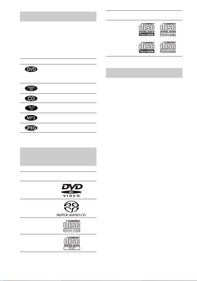
CD-R/CD-RW
(audio data)
(MP3 files)
(JPEG files)
Disc logo
Symbol Meaning
Functions available for DVD
VIDEOs, DVD-Rs/DVD-RWs in
video mode, and DVD+Rs/
DVD+RWs
Functions available in VIDEO CD
mode
Functions available in CD mode
Functions available in Super Audio
CD and Audio CD mode
Functions available for MP3* audio
tracks
Functions available for JPEG files
* MP3 (MPEG1 Audio Layer 3) is a standard format
defined by ISO/MPEG which compre sses audio data.
This System Can Play the Following Discs
Format of
discs
DVD VIDEO
Super Audio
CD
VIDEO CD
Audio CD
Disc logo
The “DVD VIDEO” logo is a trademark.
Terms fo r D is c s
• Title
The longest section of a pi ct ure or music
feature on a DVD, movie, etc., in video
software, or the entire album in audio
software.
• Chapter
Section of a picture or a music pi ece that is
smaller than titles. A title is composed of
several chapters. Depending on the disc, no
chapters may be r ecorded.
• Album
Section of a music piece or an image on a data
CD containing MP3 audio tracks or JPEG
files.
• Track
Section of a picture or a music pi ece on a
VIDEO CD, Super Audio CD, CD, or MP3.
• Index (Super Audio CD, CD) / Video
Index (VIDEO CD)
A number that divides a track into sections to
easily locate the point you want on a VIDEO
CD, Super Audio CD, or CD. Depending on
the disc, no indexes may be recorde d.
• Scene
On a VIDEO CD with PBC functions
(page 36), the menu screens, moving pictures
and still pictures are divided into sections
called “scenes. ”
• File
Section of a picture on a data CD containing
JPEG image files.
GB
6
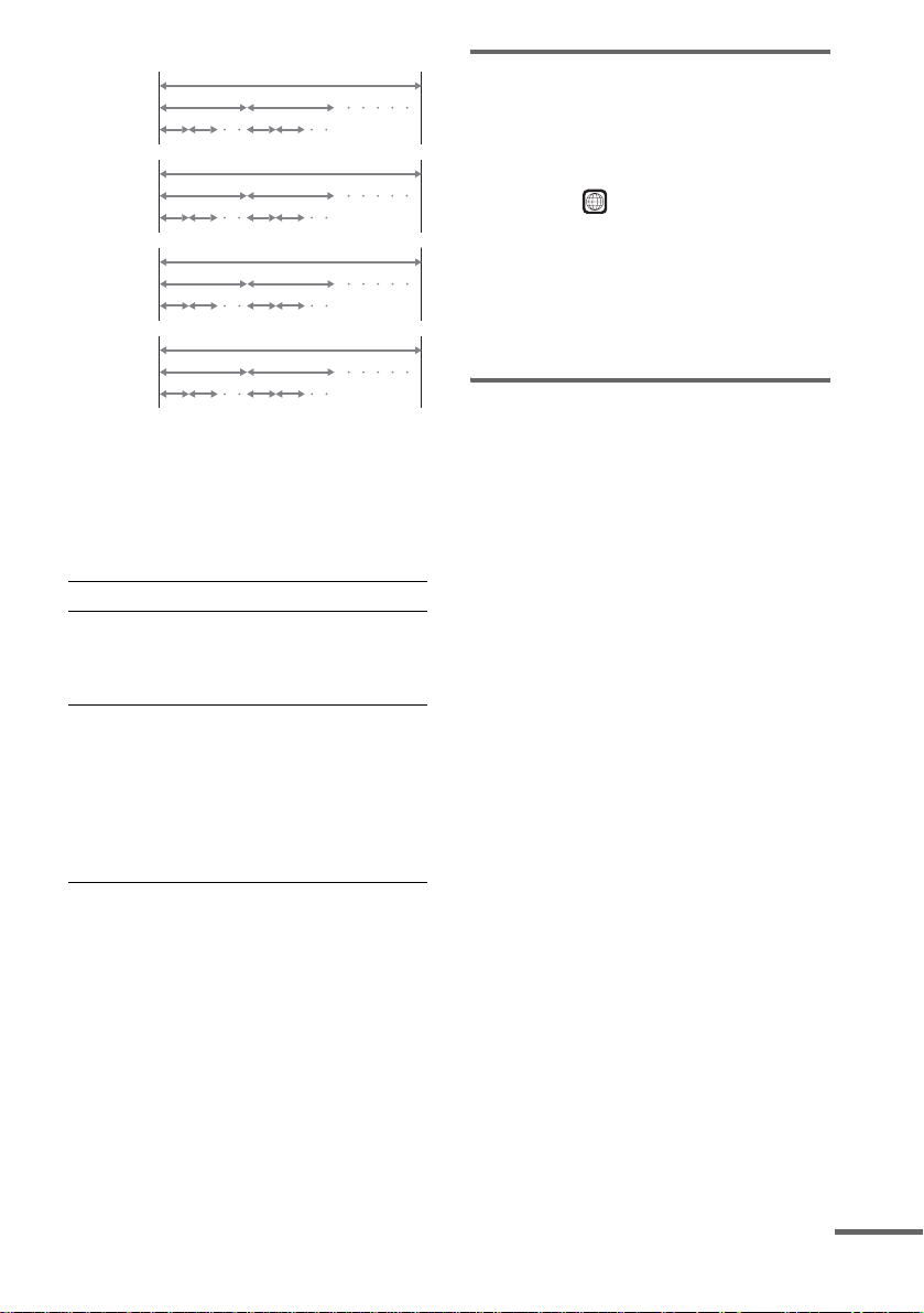
Disc
DVD
structure
VIDEO
CD, Super
Audio CD,
or CD
structure
MP3
structure
JPEG
structure
Title
Chapter
Track
Index
Album
Track
Album
File
Disc
Disc
Disc
Note on PBC (Playback Control)
(VIDEO CDs)
This system confo rms to Ver. 1.1 an d Ver. 2.0 of
VIDEO CD standards. You can enjoy two kinds
of playback depending on the disc type.
Disc type You can
VIDEO CDs
without PBC
functions
(Ver. 1.1 discs)
VIDEO CDs
with PBC
functions
(Ver. 2.0 discs)
Enjoy video playback (moving
pictures) as well as music.
Play interactive software using
menu screens displayed on the
TV screen (PBC Playback), in
addition to the video playback
functions of Ver. 1.1 discs.
Moreover, you can play highresolution still pictures, if they
are included on the disc.
About Multi Session CD
• This system can p lay Multi Ses sion CDs when
an MP3 audio trac k i s contained in th e fi rst
session. Any subsequent MP3 audio tracks
recorded in lat er sessions can also be played
back.
• This system can p lay Multi Ses sion CDs when
a JPEG image file is contained in the first
session. Any subsequent JPEG image files
recorded in lat er sessions can also be played
back.
• If audio tracks and images in music CD format
or video CD format are recorded in the first
session, only th e fi rst session will be playe d
back.
Region code
Your system ha s a region code printed on the
back of the unit and will only play DVDs labeled
with the same region code.
DVDs labeled will also play on this system.
ALL
If you try to play any ot her DVD, the message
[Playback prohibited by area limitations.] will
appear on the TV screen. Depending on the
DVD, no region code indication may be given
even though playing the DVD is prohibited by
area restrictions.
Examples of discs that the system cannot play
The system cannot play the following discs:
• CD-ROMs (except for extension “.MP3 ,”
“.JPG,” or “.JPEG”)
• CD-Rs/CD-RWs other than those recorded in
the following formats:
– audio CD format
– video CD format
– MP3/JPEG format that conforms to
ISO9660* Level 1/Level 2, or its extended
format, Joliet
• Data part of CD -Extras
• DVD-ROMs
• DVD Audio discs
• DVD-RAMs
• DVD-RWs in VR (Video Recording) mode
• Progressi ve JPEG file
* A logical format of files and folders on CD-ROMs,
defined by ISO (International Organiz a tion for
standardization)
Do not load the fo llowing discs:
• A DVD with a different region code (page7,
96).
• A disc that is neither standard nor circular
(e.g., card, heart, or star shape).
• A disc with pa per or stickers on it.
• A disc that has adhesive or cellophane tape still
left on it.
continued
GB
7
Notes about CD-R/CD-RW/DVD-R/DVD-RW (Video
mode)/DVD+R/DVD+RW
In some cases, CD-R/CD-RW/DVD-R/DVD-RW
(Video mode)/DVD+R/DVD+RW cannot be played
on this player due to the recording quality or physical
condition of the disc, or the characteristics of the
recording device and authoring sof tware.
The disc will not play if it has not been correctl y
finalized. For more information, see the operating
instructions for the recording device.
Note that discs created in the Packet Write format
cannot be played.
Music discs encoded with copyright protection
technologies
This product is designed to play back dis cs that
conform to the Compact Disc (CD) standa rd.
Recently, various music discs encoded with copyright
protection technologies are m arke ted by some record
companies. Please be aware that among those discs,
there are some that do not conform to the CD standard
and may not be playable by this product .
* Manufactured under license from Dolby
Laboratories.
“Dolby”, “Pro Logic”, and the double-D symbol are
trademarks of Dolby Laboratories.
**Manufactured under license from Digital Theater
Systems, Inc.
“DTS”, “DTS-ES”, “Neo:6”, and “DTS Digital
Surround” are trademark s of Digit al Theat er
Systems, Inc.
Notes about Discs
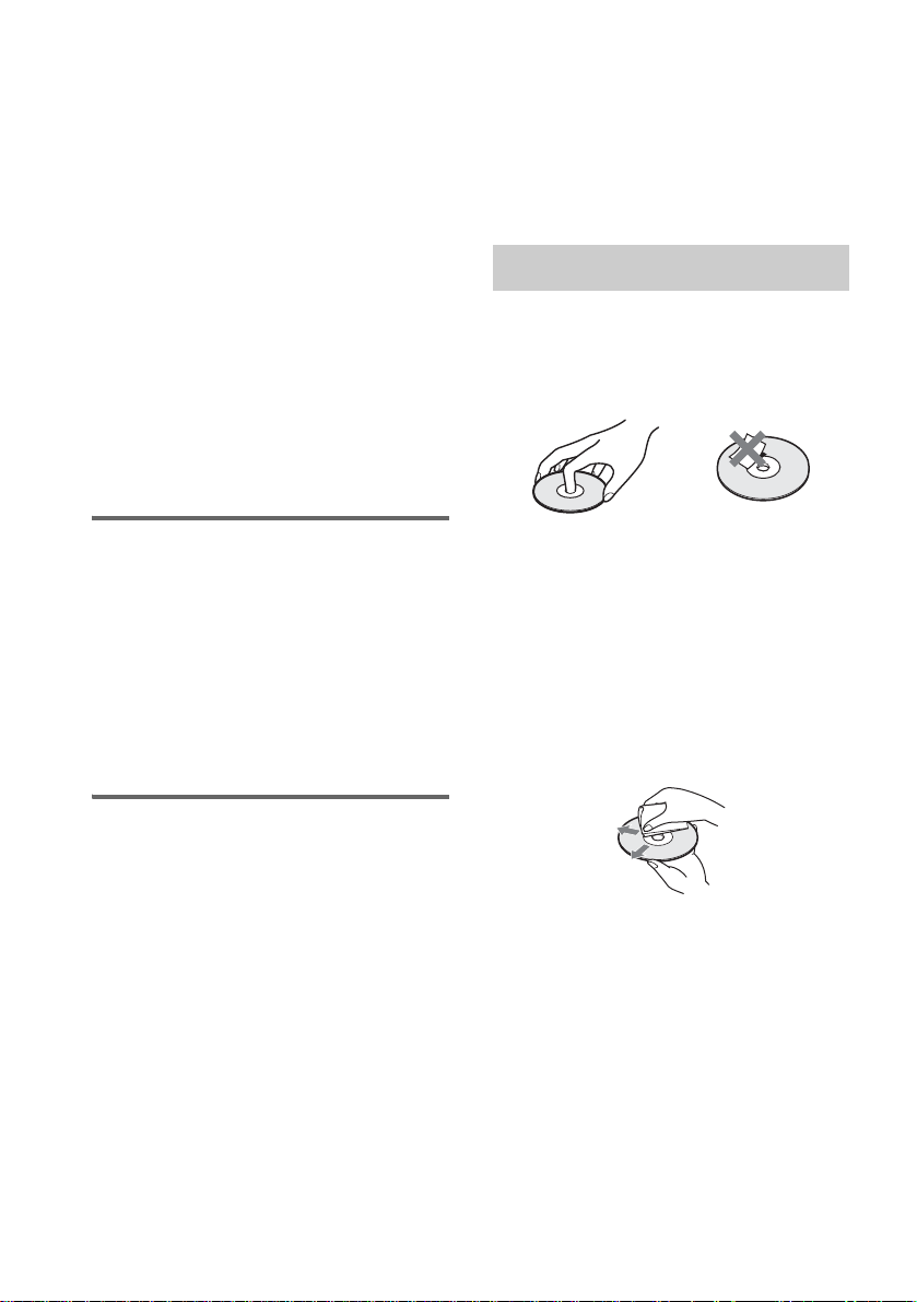
On handling discs
• To keep the disc cl ean, handle the disc by its
edge. Do not touch th e surface.
• Do not stick paper or tape on the disc.
Note on playback operations of DVDs and VIDEO CDs
Some playback operations of DVDs and VIDEO
CDs may be intentionally set by software
producers. Since this system plays DVDs and
VIDEO CDs according to the disc contents the
software producers designed, some playback
features may not be available. Also, re fer to the
instructions supplied with the DVDs or VIDEO
CDs.
Copyrights
This product incorporates copyright protect io n
technology that is protected by U.S. patents and
other intellectual property rights. Use of this
copyright protection te chnology must be
authorized by Macrovision, and is intended for
home and other limited viewing uses onl y unless
otherwise authorized by Macrovision. Reverse
engineering or dis as sembly is prohibited.
This system incorporates with Dolby* Digital
and Dolby Pro Logic (I I) adaptive matrix
surround decoder and the DTS** Digital
Surround System.
• Do not expose t he disc to direct sunlight or
heat sources such as hot air ducts, or leave it in
a car parked in direct sunlight as the
temperature ma y rise considerably inside the
car.
• After playing, store the disc in its case.
On cleaning
• Before play i ng, clean the di sc with a cleaning
cloth.
Wipe the disc from the center out.
• Do not use solvents such as benzine, thinner,
commerciall y avai labl e clea ners, or anti -stat ic
spray intended for vinyl LPs.
This system can only play back a standard
circular dis c. Using ne ither stan dard nor cir cular
discs (e.g . , card, hear t , or star shape) may ca use
a malfunction.
Do not use a disc that has a commercially
available accessory attached, such as a label or
ring.
GB
8
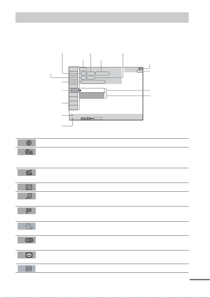
Guide to the Control Menu Display
Use the Control Menu to select a function that you would like to use. The Control Menu display appears
when the DVD DISPLAY button is pressed. For details, refer to the page in parentheses.
Total number of
Currently playing title number (VIDEO
CD/Super Audio CD/CD: track number)
Currently playing ch apter
number (VIDEO CD/Super
Audio CD/CD: index number)
Playing time
Icon of selected
Control Menu item
Control Menu items
titles or tracks
recorded
Disc name or
disc type
DVD
1 2 ( 2 7 ) TITLE 12
1 8 ( 3 4
T
1: ENGLISH
2: FRENCH
3: SPANISH
Currently playing
title name
)
1 : 3 2 : 5 5
Total number of chapters or indexes recorded
Playback status
(NPlayback, XPause, xStop, etc.)
DVD
Type of disc being
played back
Current setting
Options
Function name of selected
Control Menu item
Operation message
SUBTITLE
Select:
List of Control Menu Items
DISC Displays the di sc name or the disc type inser ted into the system.
TITLE (DVD only) (page 46)/
SCENE (only VIDEO CD in PBC playback) /
TRACK (VIDEO CD only) (page 46)
CHAPTER (DVD only) (page 47)/
INDEX (VIDEO CD only) (page 47)
ALBUM (MP3 only) (page 38, 46) Selects the album (MP3) to be pla ye d.
TRACK (Super Audio CD/CD/
MP3 only) (page 38, 46)
INDEX (Super Audio CD/CD only)
(page 47)
TIME (page 47) Checks the elapsed time and the remaining playback time.
AUDIO (DVD/VIDEO CD/Super
Audio CD/CD/MP3 only) (page52)
SUBTITLE (DVD only) (page 62) Displays the subtitles.
ENTER
Selects the title (DVD), or the track (VIDEO CD) to be
played.
Displays the scene (VIDEO CD in PBC play b ack).
Selects the chapter (DVD) or the index (VIDEO CD) to be
played.
Selects the track (Super Audio CD/CD/MP3) to be played.
Displays the index and selects the index (Super Audio CD) to
be played.
Inputs the time code for picture and music searching.
Changes the audio setting .
Changes the subtitle langua ge .
ALBUM (JPEG only) (page 39) Selects the album (JP EG ) to be played.
continued
GB
9
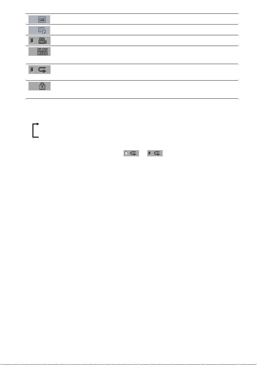
FILE (JPEG only) (page 39) Selects the file (JPEG) to be played.
DATE (JPEG only) (page 51) Displays the date information.
ANGLE (DVD onl y) (p a ge 61) Changes the angle.
PLAYMODE (VIDEO CD/Super
Audio CD/CD/MP3/JPEG only) (page43)
REPEAT (page 44) Plays the entire disc (all titles/all tracks), one title/chapter/
CUSTOM PARENTAL
CONTROL (page 63)
Tips
• Each time you press DVD DISPLAY, the Control Menu display changes as follows:
Control Menu display
Selects the play mode.
track/album, or contents of program repeatedly.
Sets the disc to prohibit playing.
m
Control Menu display off
The Control Menu items vary, depending on the disc.
• The Control Menu icon indicator lights up in green t unless you se t th e [ REPEAT] setting to
[OFF].
• The [ANGLE] indicator lights up in green only when multiple angles are recorded on the disc.
10
GB
Getting Started
Unpacking
Check that you have the following items:
•Speakers (5)
• Subwoofer (1)
• IR transmitter
• IR receiver
• IR receiver stand
• AM loop antenna (aerial) (1)
• FM wire antenna (a erial) (1)
• Speaker co rds (3.5m × 3, 10 m × 1)
• Remote Com m ander (remote) RM-SP320 (1)
• Size AAA (R03) batteries (2)
• Operating Instructions
• Speakers - Connection and Installation (card)
(1)
a)
The cords of the IR transmitter and IR receiv er are
for this system only. You cannot use a
commercial ly available exte n sion cord.
b)
Used when the IR receiv er of the surround s peaker
(L) cannot receive infrared ray beca use of the
position. For details, see “Using the IR rec eiv e r ”
(page 27).
a)b)
a)
(1)
(1)
b)
(1)
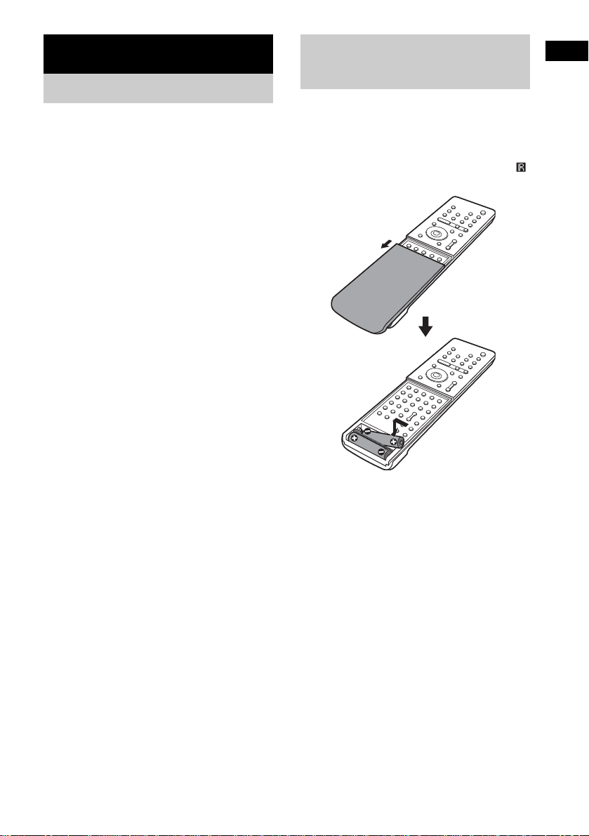
Inserting Batteries into
Getting Started
the Remote
You can control the system using the supplied
remote. Insert two size AAA (R03) batteries b y
matching the 3 and # ends on the batteries to
the markings inside the compartment. When
using the remote, point it at the remote s ensor
on the system.
Remove the cover.
Notes
• Do not leave the remote in an extremely hot or humid
place.
• Do not use a new battery with an old one.
• Do not drop any foreign object into the remote casing,
particularly when replac ing th e ba tteries.
• Do not expose the remote sensor to dir ect li ght from
the sun or lighting apparatus. Doi ng so ma y c au se a
malfunction.
• If you do not use the remote for an extended period of
time, remove the batteries to avoid possible damage
from battery leakage and corros ion.
11
GB
Step 1: Speaker System Hookup
Connect the supplied speaker system usi ng the supplied speaker cor ds by matching the colors of the
jacks to those of the cords. Do not connect any speakers other than those supplied with this system.
To obtain the best possible surround sound, specify the speak er par ameters (distance, level, etc.) on
page 32.
Required cords
Speaker cords
The connector and the color tube of the speaker cords are the same color as the label of the jacks to be
connected.
(–)
(+)
color tube
(–)
(+)
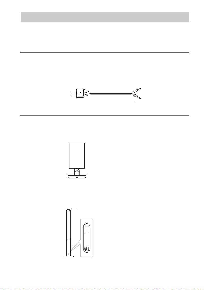
Required equipments for the wireless system
IR transmitter
Transmits the sound by the infrared ray. Connect it to the system.
Surround speaker (L)
The surround speaker (L) incorpora tes the IR receiver. It re ceives the sound from the IR tra nsmitter and
sends it to the surround speaker (R).
Connect the sur round speaker (R).
IR receiver
POWER
ON
12
OFF
ONLY FOR
DIR-R2
Rear side of the surround speaker (L)
GB
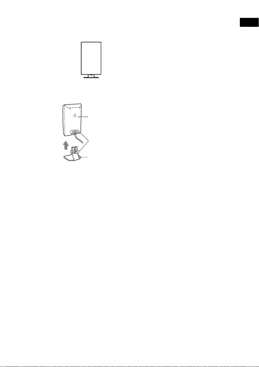
IR receiver
Used when the IR receiver of the surround speaker cannot receive infrared ray because of the position.
Connect to the sur round speaker (L). For de ta ils, see “Using the IR receiver” (page 27).
When using the IR receiver stand, attach the stand so that both delta marks on the IR receiver and stand
are aligned.
IR receiver
Delta marks
IR receiver stand
Note
When you connect the IR receiver to the surround speaker (L), the IR receiver is activated and the IR receiver of the
surround speaker (L) is not activated automatically.
Getting Started
13
GB
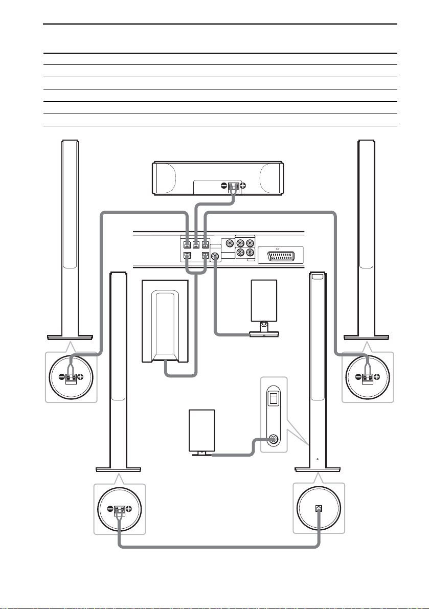
Terminals for connecting the speakers
Connect the To the
Front speakers SPEAKER FRONT L (white) and R (red) jacks of the system
Center speaker SPEAKER CENTER (green) jack of the system
Subwoofer SPEAKER WOOFER (purple) jacks of the system
Surround speaker (R) SPEAKER (gray) jack of the surround speaker (L)
IR transmitter DIR-T1 (pink) jack of the system
Bottom of the
front speaker
Surround
speaker (R)
Front speaker (R)
Center speaker
SPEAKER
CENTER FRONT LFRONT R
Subwoofer
IR receiver
Use when you do not use
the IR receiver of the
surround speaker (L)
(page 27).
Bottom of the
surround speaker
RL
DIR-T1
SURROUND
RL
BACK
WOOFERWOOFER
Rear side of the
surround speaker (L)
Bottom of the
surround speaker
VIDEO
AUDIO IN
EURO AV OUTPUT(TO TV)
AUDIO IN
SAT
IR transmitter
POWER
ON
OFF
ONLY FOR
DIR-R2
Front speaker (L)
Bottom of the
front speaker
Surround
speaker (L)
with IR receiver
ONLY FOR
SS-TS21
SPEAKER
14
GB
Note on placing speakers
• Do not set the speakers in an inclined position.
• Do not place the speakers in locations that ar e:
– Extremely hot or cold
– Dusty or dirty
– Very humid
– Subject to vibrations
– Subject to direct sunlight
• Use caution when placing the subwoofer or tall speakers on a specially treated (waxed, oiled, polished, etc.) floor,
as staining or discoloration ma y result.
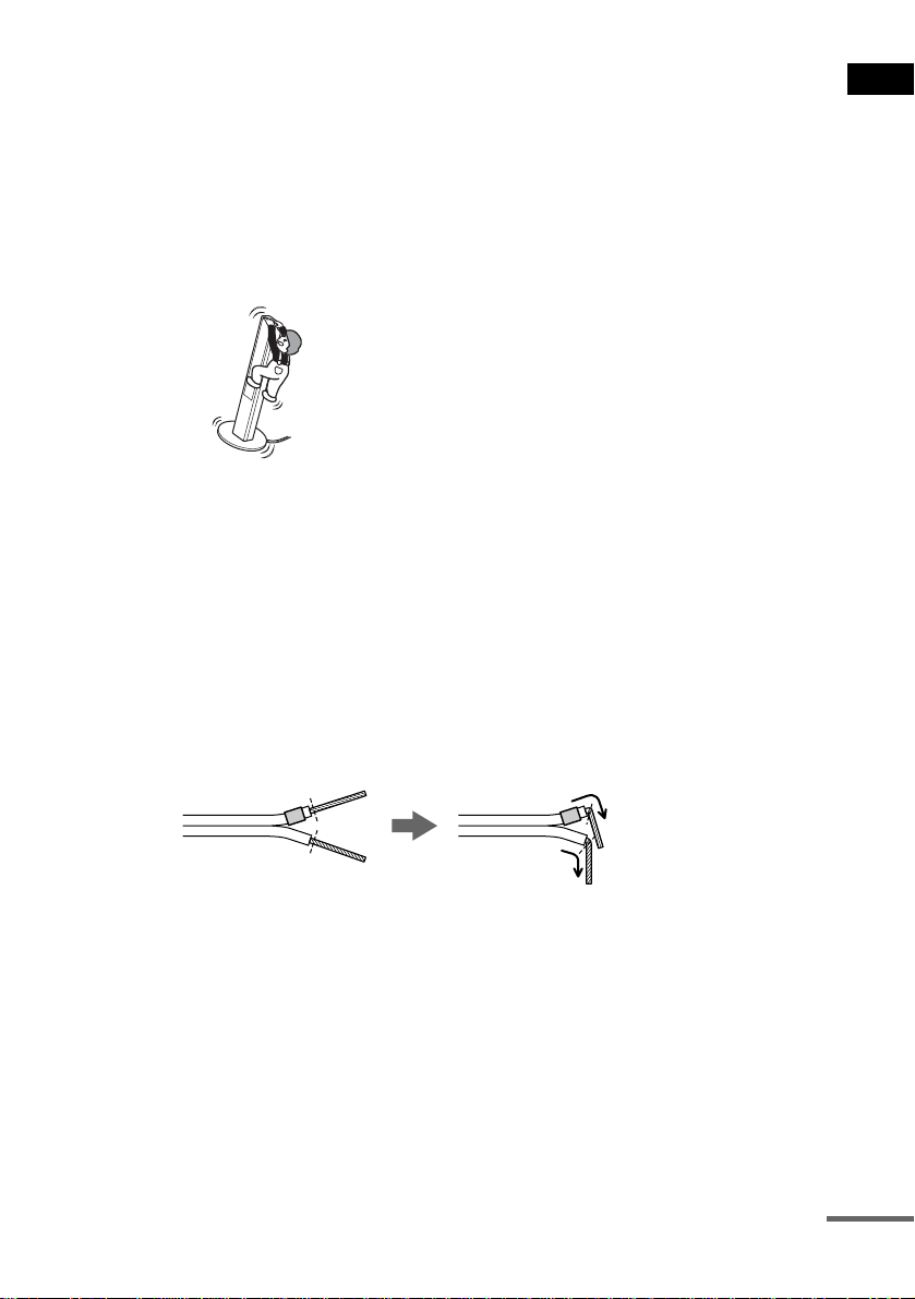
• Do not lean or ha ng on the spe ak er, as th e spea ke r may fall down.
Notes on placing IR transmitter and surround speaker (L) (or IR receiver)
• Do not install the surround speaker (L) (or IR receiver) in a place exposed to direct sunlight or strong light such as
an incandescent la mp.
• The cords of the IR transmitter and IR receiver are for th is sys tem only. You cannot use a commercially available
extension cord.
Tip for the surround speaker (L)
You can swap the surround speaker (L) and (R) positions, depending on the wall outlet and speaker layout (page 24).
Note
Do not catch the speaker cab le insulation in the SPEAKER jack.
Tip
Connect the speaker cable aft er bendi ng the speak er wire at the en d of the in sulation . This pre vents the speaker ca ble
from being caught in the SPEAKER jack.
Getting Started
continued
15
GB
To connect the surround back speaker
This system is compatible with the 6.1 surround system. When you enjoy a DVD that is compatible
with the 6.1 surround system such as a DTS-ES disc, connect the surround back speaker (not supplied)
and set its param eters (see “Settings fo r t h e Speakers” on page 83).
SPEAKER
VIDEO
AUDIO IN
DIR-T1
SURROUND
RL
RL
BACK
AUDIO IN
EURO AV OUTPUT(TO TV)
SAT
CENTER FRONT LFRONT R
WOOFERWOOFER
OPTICAL
DIGITAL IN
AM
FM 75
COAXIAL
SAT
Amplifier
AUDIO
IN
Surround back speaker
Tip
You can also enjoy the 6.1 surround sound when you pl ay a 2 or 5.1 chann el sour c e by using the sur r ound back
decoding function (see “Selecting the Surround Back Decoding Mode” on page 58).
To avoid short-circuiting the speakers
Short-circuiting of the speakers may damage the system. To prevent this, be sure to follow these
precautions w hen conne cting the speakers. Ma ke sure th e bare wire of each spea ker cord do es not tou ch
another speaker jack or the bare wire of anot her speaker cord.
Examples of poor conditions of the speaker cord
Stripped speaker cord is
touching another speaker
terminal.
Stripped cords are touching
each other due to excessive
removal of insulation.
16
After connectin g al l the components, speakers , an d A C power cord (mains lead), out put a test tone to
check that all the speakers are connected correctly. For details on outputting a test tone, see page 85.
If no sound is heard from a speaker while outputting a test tone, or a test tone is output from a speaker
other than the one currently displayed in the front panel display, the speaker may be short-circuited. If
this happens, check the speaker connect i on again.
Notes
• Be sure to match the speaker cord to the appropr iate termi nal on the c omponent s: 3 to 3, and # to #. If the cords
are reversed, the sound will lack bass and may be distorted.
• If you connect the speaker cord incorrect ly or t urn up the vo lume i n a stat e of a s hort ci rcui t, “PR OTEC T” app ears
in the front panel display and the system e nte r s sta ndby mode. In this case, disconnect and then reconnect th e AC
power cord (mains lead) from the wall outlet (mains), and then turn the system on.
GB
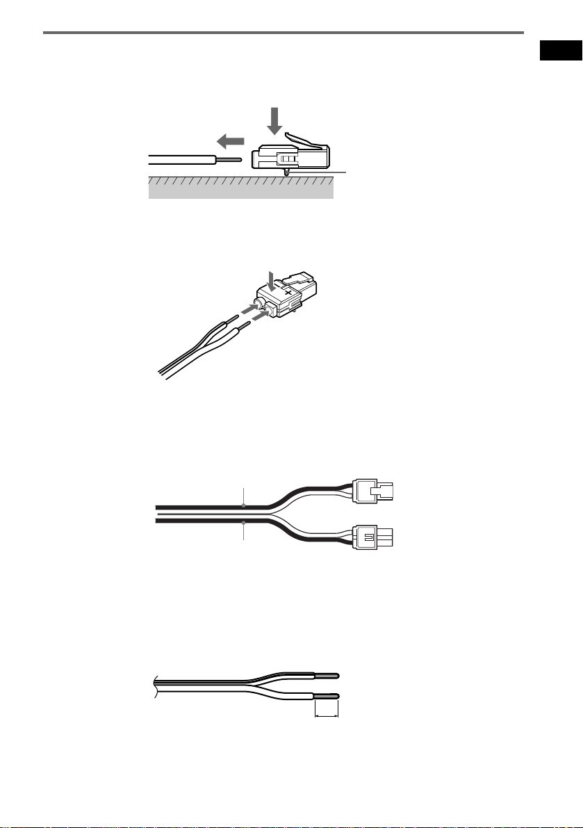
To change the speaker cables
If you want to use a different speaker cable, you can detach the plug for attachment to another cable.
Detaching
Catcher
With the catcher facing down, press and hold the plug down against a flat surface and remove the cords
from plug.
Attaching
While pressing t he plug down against a flat surface, insert the new speaker cords.
Note that the cord marked with a line should be attached to the minus (-) side of the plug.
Notes
• Be careful not to damage the surface you use (desk, etc.) when atta ch in g /detaching the speaker cords.
• When using the subwoofer cord, note that the two outside black cords or the cords marked with letters are negative.
(–)
(–)
(+)
Getting Started
(+)
(–)
• If you connect the subwoofer cord incorrectly or turn up the volume in a state of a short circuit, “PROTECT”
appears in the front panel display and the system enters standby mode. In this case, disconnect and then reconnect
the AC power cord (mains lead) from the wall outlet (mains), and then turn the sys t em on.
Tips
• You can use any commercially sold speaker cable of gauge cord AWG #18 - AWG #22.
• B efore attaching a new cable, strip off 10 mm (13/32 in.) of its insulat ion and twist the bare wires of both cords.
10 mm
(–)
17
GB
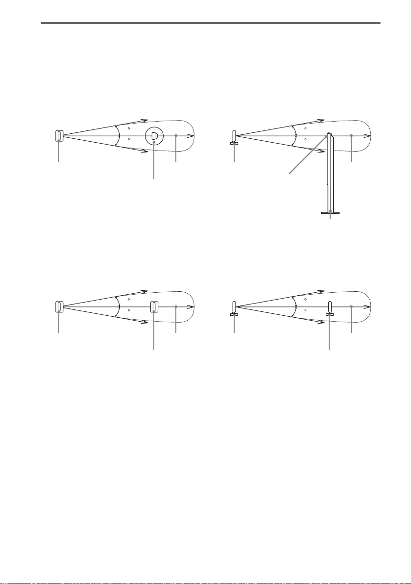
About the wireless system
This wireless system adopts the Digital Infra red Audio Transmission sy stem (page 94). The following
diagram indic at es the infrared transmis si on area (the range that the inf rared rays can reach).
When using the IR receiver of the surround speaker (L)
Top view
IR transmitter
Infrared signal
10
10
Approx. 10m
Surround speaker (L)
Side view
IR transmitter
Infrared signal
10
10
Approx. 10m
IR receiver
Surround speaker (L)
When using the IR receiver
Top view
Infrared signal
10
10
IR transmitter
IR receiver
Notes
Approx. 10m
• Do not install the surround speaker (L) (or IR receiver) in a place exposed to direct sunlight or strong light such as
an incandescent lamp.
• Do not use the surround speaker (L) (or IR receiver) that is not supplied with the system.
Side view
IR transmitter
Infrared signal
10
10
Approx. 10m
IR receiver
18
GB
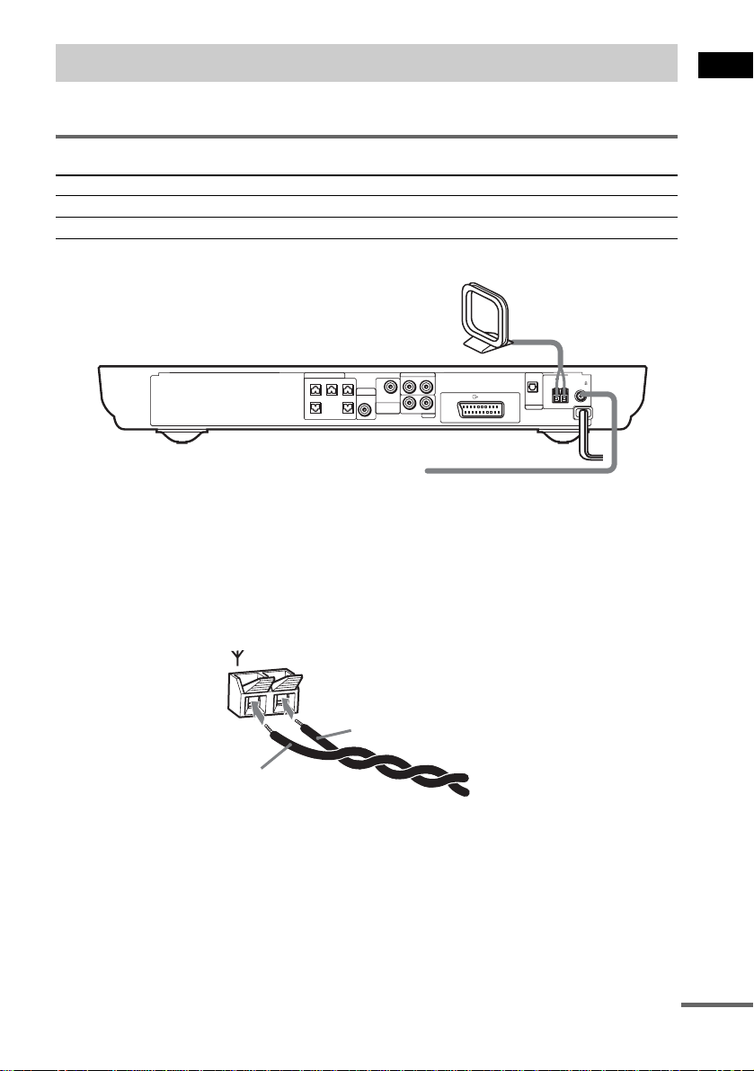
Step 2: Antenna (aerial) Hookups
Connect the supplied AM/FM antennas (aerials) for listening to the radio.
Terminals for connecting the antennas (aerials)
Connect the To the
AM loop antenna ( aerial) AM terminals
FM wire antenna (ae r ial) FM 75Ω COAXIAL jack
AM loop antenna (aerial)
Getting Started
SPEAKER
VIDEO
AUDIO IN
DIR-T1
SURROUND
RL
RL
BACK
AUDIO IN
SAT
EURO AV OUTPUT(TO TV)
CENTER FRONT LFRONT R
WOOFERWOOFER
OPTICAL
DIGITAL IN
AM
FM 75
COAXIAL
SAT
FM wire antenna (aerial)
Notes
• To pr e ve nt noise pickup, keep the AM loop antenna (aerial) away from the system and other components.
• B e sure to fully extend the FM wire antenna (aerial).
• Af te r con nec t ing the FM wire antenna (aerial), keep it as horizonta l as possible.
Tip
When you connect the supplied AM loop ant en na (a eria l), the cord (A) and the cord (B) can be connected in either
terminal.
AM
A
B
continued
19
GB

Tip
If you have poor FM reception, use a 75-ohms coaxial cable (not supplied) to connect the system to an outdoor
FM antenna (aerial) as shown below.
Outdoor FM
antenna (aerial)
System
AM
FM 75
COAXIAL
20
GB
Step 3: TV and Video Component Hookups
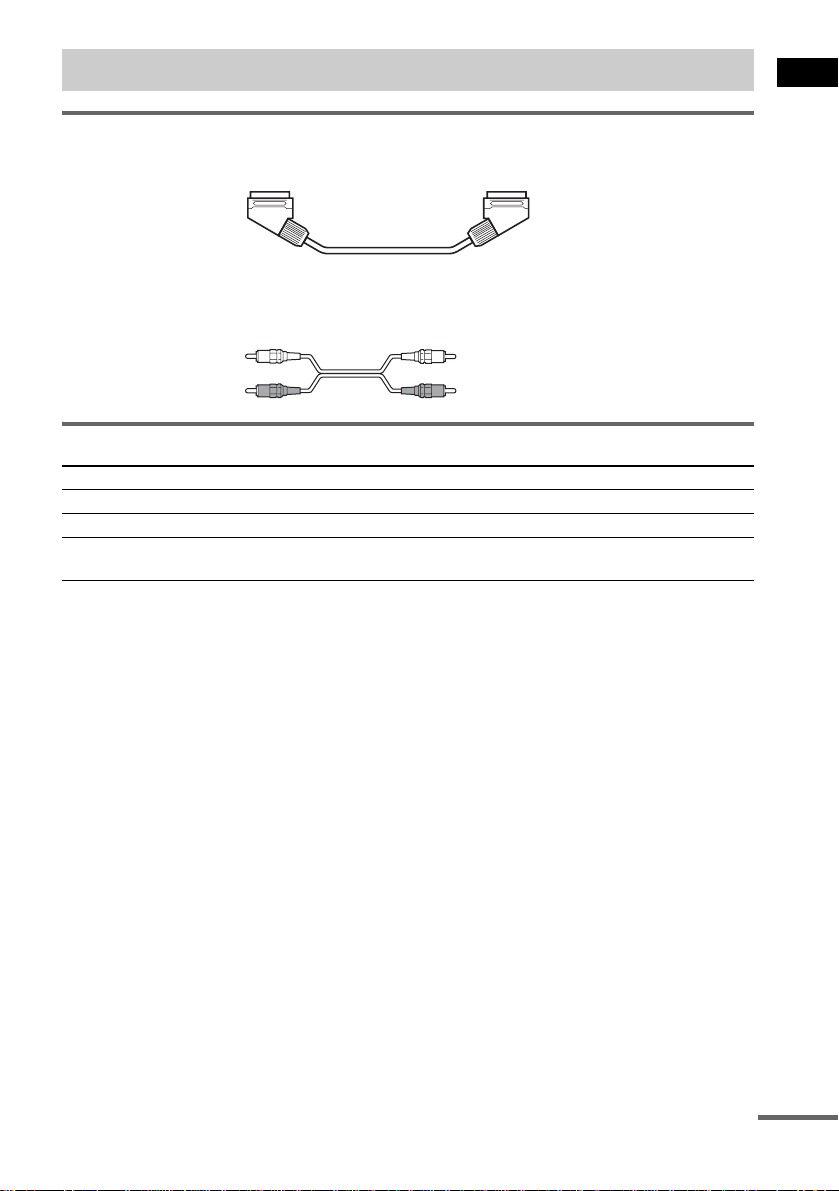
Required cords
SCART (EURO AV) cord for connecting a TV (not supplied)
Audio cords (not supplied)
When connectin g a cord, be sure to match the color-coded sleeves to th e appropriate jacks on the
components.
White (L/audio)
Red (R/audio)
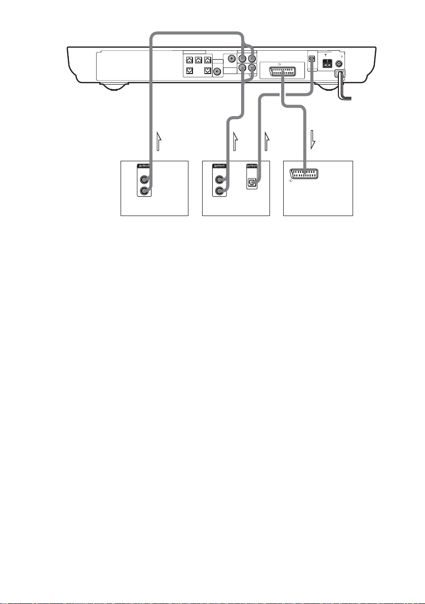
Terminals for connecting video compon ent s
Connect the To the
TV (VIDEO IN) T EURO AV OUTPUT (TO TV) jack
VCR (AUDIO OUT) VIDEO (AUDIO IN) jacks
Digital satellite rec ei ver
(AUDIO OUT)
Connecting the system to a TV
Connect the system t o your TV using the SCART (EUR O A V ) cord. Be sure to connect the S CA R T
(EURO AV) cord to the T EURO AV OUTPUT (TO TV) jack on the system.
When you connect using the SCART (EURO AV) cord, check that the TV conforms to S video or RGB
signals. If the TV conforms to S vid eo, change the input mode of the TV to RGB signals. Refer to the
operating instructions supplied with the TV to be connected.
SAT (AUDIO IN) jacks
Getting Started
continued
21
GB
SPEAKER
VIDEO
AUDIO IN
DIR-T1
SURROUND
RL
RL
BACK
AUDIO IN
EURO AV OUTPUT(TO TV)
SAT
CENTER FRONT LFRONT R
WOOFERWOOFER
OPTICAL
DIGITAL IN
AM
FM 75
COAXIAL
SAT
OUT INOUT OUT
AUDIO
OUT
L
R
VCR
AUDIO
L
R
Digital satellite receiver or
PlayStation 2 etc.
OPTICAL
OUT
DIGITAL
OUT
EURO AV
INTPUT(FROM VIDEO)
TV
Notes
• Make connections securely to prevent unwanted noise.
• Refer to the instruc tions supplied with the TV.
• The system cannot output component video signals.
• The system cannot output an audio signal to the connected TV. Only the audio signal of the TV is output from the
system speakers.
Tips
• When you want to output the TV sound or stereo sound of a 2 channel source from the 6 speakers, select any sound
field other than “AUTO FORMAT DIRECT AUTO” or “2CH STEREO” (page 54).
• If a distortion occurs during playback of the component that is connected to the VIDEO AUDIO IN jacks, connect
the component to the SAT AUDIO IN jacks.
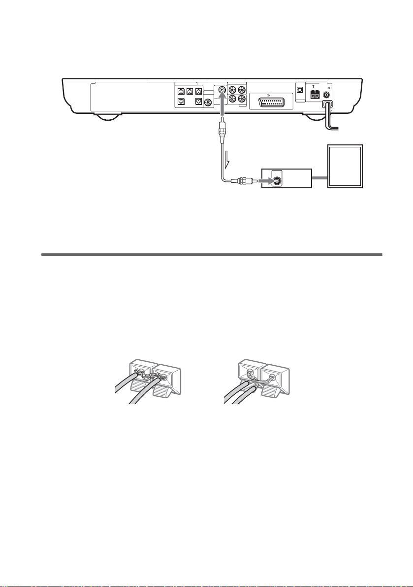
If you connect a digital satellite receiver with an OPTICAL OUT jack
The digital satellite receiver can be connect ed to th e SAT OPTICAL DIGITAL IN jack ins tead of the
SAT AUDIO IN (L/R) jacks of the system.
The system can accept bo th the dig ital and an alogue si gnals. Di gital si gnals hav e priori ty over anal ogue
signals. If the digital signal ceases, the analogue signal will be processed after 2 seconds.
If you connect a digital satellite receiver without an OPTICAL OUT jack
Connect the digital satellite receiver to the SAT AUDIO IN (L/R) jacks only of the system.
To listen to the game machine (e.g., PlayStation 2) sound by using the
system
Connect the audio output ja cks of the game machine to the SAT AUDIO IN (L/R) jacks of th e system
with the audio cord s (not supplied).
Notes
• The system does not output S video signals.
• When you select VIDEO or SAT by pressing FUNCTION (page 72), the audio signal from the AUDIO IN (L/R)
jack is output to the connected speakers. The audio signal is not output from the T EURO AV OUTPUT (TO TV)
jack.
22
GB

When connecting to a standard 4:3 screen TV
Depending on the disc, the image may not fit your TV screen.
If you want to change the aspect ratio, please refer to page 80.
Getting Started
23
GB
Step 4: Connecting the AC Power Cords (Mains Leads)
Before connecting the AC power cords (mains lead s) of this system and the surroun d speaker (L) to a
wall outlet (mains), connect the front and center speakers to the system and surround speaker (R) to the
surround speaker (L) (see page 14).
When placing the surround
speaker (L) in the (R) position
Depending on the lo cat ion of the wall outlet
(mains), you can also place the surround speaker
(L) (with the IR receiver) in the (R) position if
necessary.
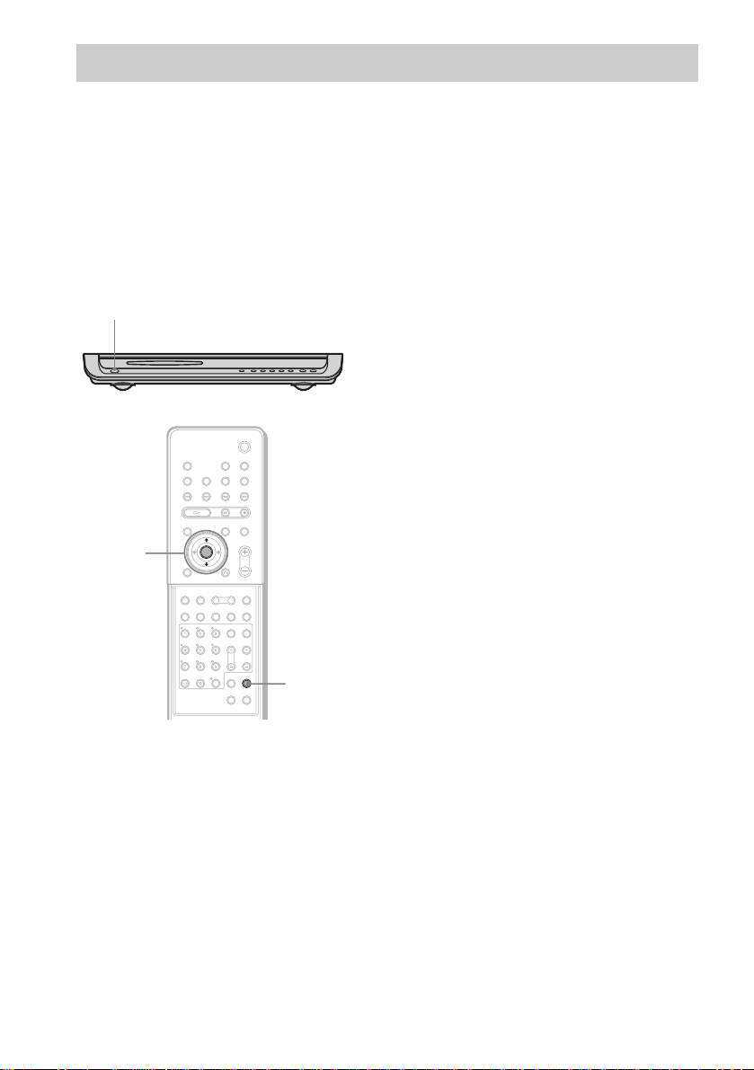
"/1
4 Press X/x repeatedly until “SL SR
REV” appears in the front panel
display, then press ENTER or c.
5 Press X/x repeatedly until the item you
want to set appears in the front panel
display.
xOFF (default)
Sets the surround speaker (L) (with the IR
receiver) in the (L) position.
xON
Sets the surround speaker (L) (with the IR
receiver) in the (R) position.
6 Press AMP MENU.
The AMP menu turns off.
C/X/x/c/
ENTER
24
AMP MENU
With cover opened.
1 Press "/1 on the system to turn the
system on.
2 Press AMP MENU.
3 Press X/x repeatedly until
“CUSTOMIZE” appears in the front
panel display, then press ENTER or c.
The system enters the Customize Menu
mode.
GB
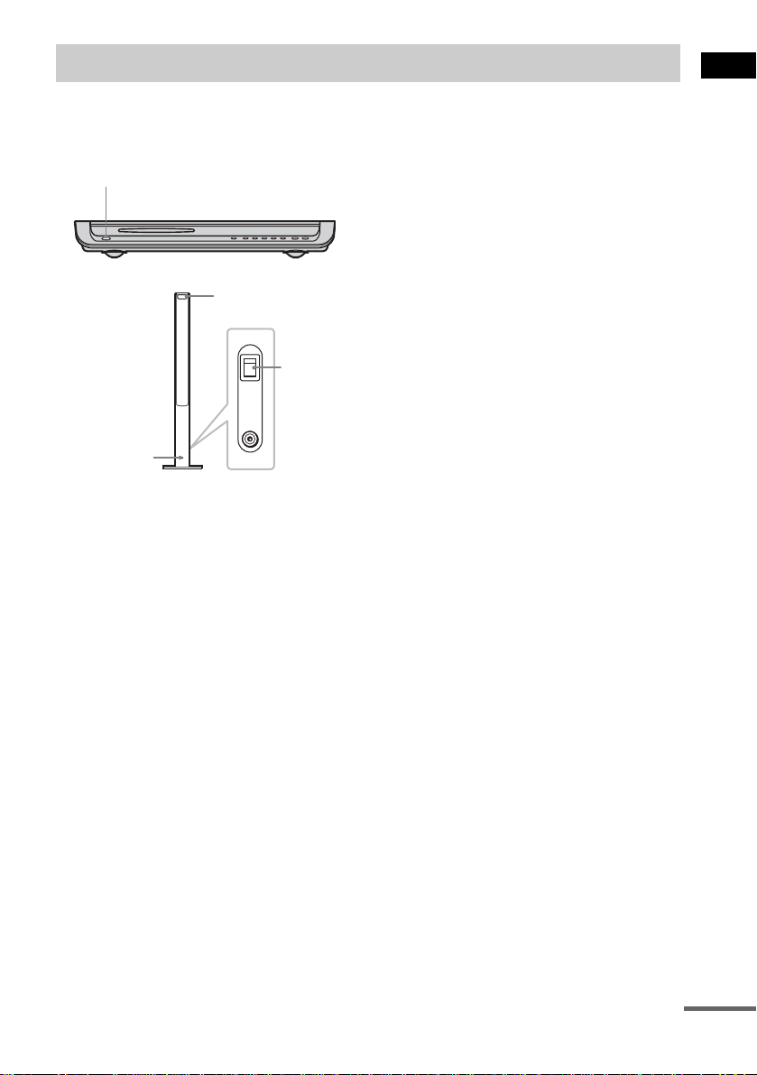
Step 5: Adjusting the Wireless System
After connecting the speakers, IR transmitter,
and the AC power cords (mains leads), ad ju st
the wireless system for good transmission.
"/1
IR receiver
POWER
ON
POWER
OFF
ONLY FOR
DIR-R2
POWER/ON
LINE indicator
Rear side of the
surround speaker (L)
Tip
The IR transmitter is movabl e for easy r e orientation.
Notes
• Make sure that there is no obstruction such as a
person or object between the IR transmitter and the IR
receiver of the surround speaker (L). Otherwise, the
sound from the surround speakers may be interrupted.
• If the POWER/ON LINE indicator turns red, the
transmission is incomplete. Adjust the position of the
IR transmitter and surround speake r (L) unt il the
POWER/ON LINE indicator turns green.
• If the POWER/ON LINE indicator flashes in red, the
IR receiver of the s urround speaker (L) is receiving an
infrared ray from another Sony’s wireless product.
Move the IR transmi tt er and/or the surround s p eak er
(L) so that the POWER/ O N LINE in dicator turns
green.
1 Press "/1 on the system and POWER
on the surround speaker (L) to turn on.
The system and surround speaker (L) turn
on and the POWER/ON LIN E i ndi c at or
turns red.
2 Orient the IR transmitter and the IR
receiver of the surround speaker (L) to
face each other.
Adjust the position until the POWER/ON
LINE indi c ator turns gre en.
Getting Started
continued
25
GB
Example for installation
Position the IR transmitter and surround speaker (L) as illustrated.
Install the IR transmitter and IR receiver of the su rround speake r (L) in direct li ne with each oth er, and
adjust the orientation of the IR transmitter and surround speaker (L) until the POWER/ON LINE
indicator turns green.
Top view
IR transmitter
IR receiver of the
surround speaker (L)
Front
speaker (L)
Surround
speaker (L)
Center speaker
TV
Listening position
Front
speaker (R)
Subwoofer
Surround
speaker (R)
26
GB
Using the IR receiver
Depending on th e speaker layout (i.e. when placing the surround speaker (L) toward the listening
position, etc.), or when there is obstruc tio n , such as a person or objec t betwe en the IR tra ns mitte r a nd
the IR rece iver of the su rround s peaker ( L), yo u can use the e xterna l IR re ceiver (suppli ed) i nstead. The
IR receiver is compact and easy to install.
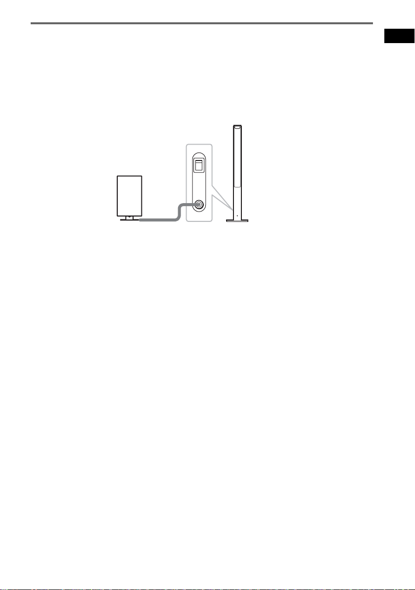
To connect the IR receiver
Connect the cord of the IR receiver to the DIR-R2 jack of the surround speaker (L).
Rear side of the
surround speaker (L)
POWER
ON
OFF
ONLY FOR
IR receiver
Notes
• Whe n you connect the IR receiver to the surround speaker (L), the IR receiver is activated and the IR receiver of
the surround speaker (L ) is not activated automatically.
• When using the IR receiver, install it following the guidelines of the IR receiver of the surround speaker (L).
DIR-R2
Getting Started
27
GB
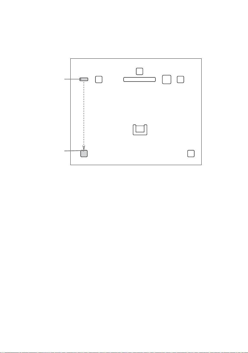
Hanging the IR transmitter and IR receiver on a wall
You can hang the IR transmitter and IR receiver on a wall when:
– there is an obstruction between the IR transmitter and the IR receiver.
– people often pass between the IR transmitter and the IR receiver.
When hanging both the IR transmitter and IR receiver, adjust the position of the IR transmitter after
deciding the posi t ion of the IR receiver.
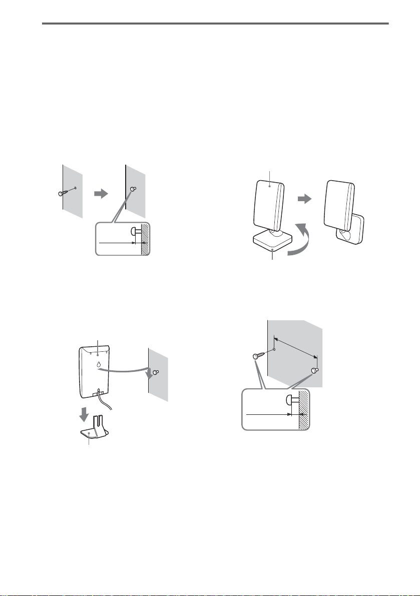
To hang the IR receiver on a wall
1 Install a commercially available screw
in the wall so that it protrudes 4 mm.
4 mm
To hang the IR transmitter on a
wall
1 Rotate the stand of the IR transmitter.
IR transmitter
Stand
2 Detach the IR receiver stand and hang
it via hole on the rear side of the IR
receiver on the screw.
Make sure that the IR receiver does not
move after installation.
IR receiver
2 Install 2 commercially available screws
in the wall so that it protrudes 4 mm.
Install the screws 30 mm apart.
30 mm
28
4 mm
IR receiver stand
Tip
When reattaching the IR receiver stand to the IR
receiver, attach the stand so that both delta marks on
the IR receiver and stand are alig ned (page 13).
GB
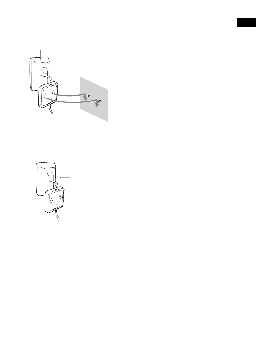
3 Hang the IR transmitter via hole on the
bottom of the stand on the screw.
Make sure that the IR transmitter does not
move afte r installatio n .
IR transmitter
Stand
Tip
You can store the cords in the troughs in the bottom of
the stand.
Stand
Notes
• Use screws suitable for the material and strength of
the wall.
• Do not install the IR tran smitter or IR receiver to a
wall of low strength.
• Sony is not liable for any damage or accident incurred
by incorrect installation (i.e. low strength wall, etc.),
incorrect use of this product, or natu ral disaster.
• When connecting/disconnecting cords, detach the IR
transmitter or IR receiver from the wall first.
Getting Started
Troughs
29
GB
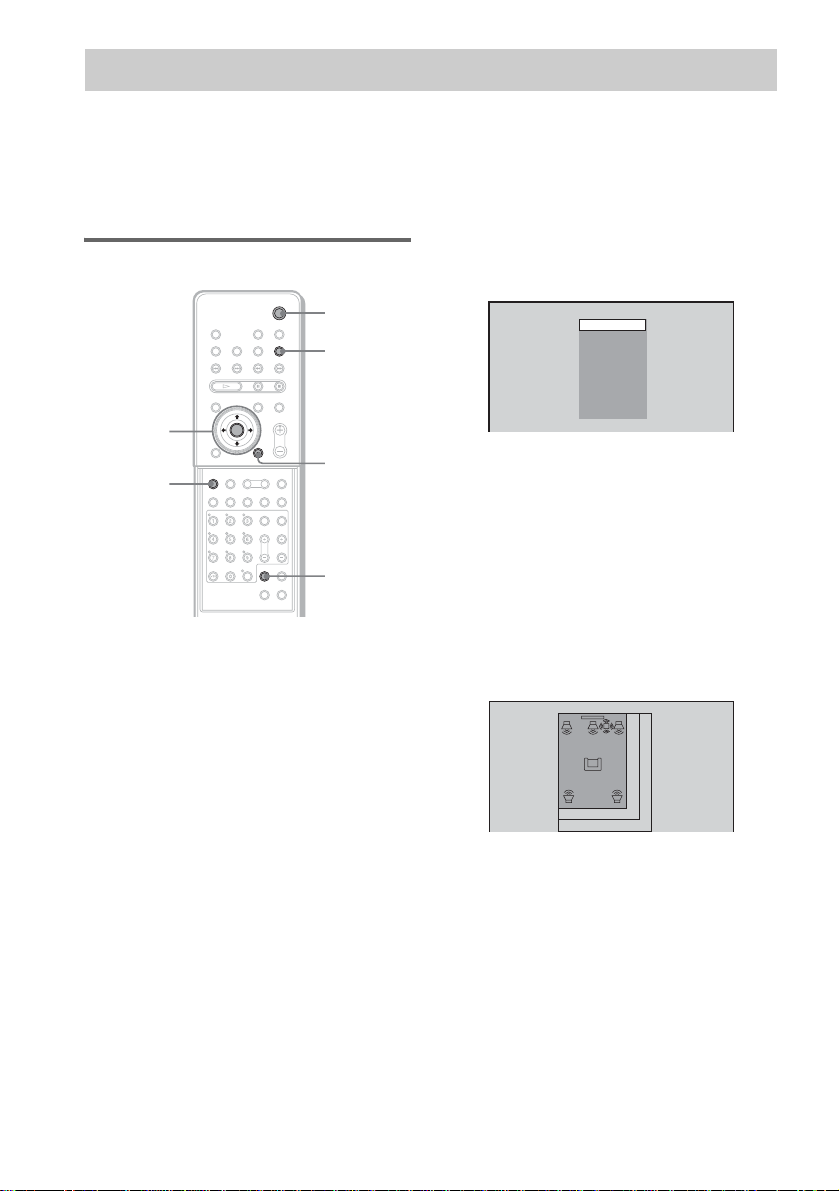
Step 6: Performing the Quick Setup
After completing the first 4 steps, make initial settings using the Quick Setup. You can set the initial
setting of [LANGUAGE SETUP], [ROOM SIZE], [LISTENING POSITION], and [TV TYPE] step by
step.
After performing the Quick Setu p, th e system is read y for p laying back of mo vies, mu sic CDs, etc. To
perform further speakers settings, see “Settings for the Speakers” on page83.
How to use the Quick Setup
"/1
FUNCTION
C/X/x/c/
ENTER
DVD
SETUP
With cover opened.
O RETURN
CLEAR
1 Turn on your TV.
2 Switch the input selector on the TV to
this system.
3 Press "/1.
4 Press FUNCTION to select “DVD.”
The guide message appears on the TV
screen.
Note
When a disc is in the system, the guide message
does not appear on the TV screen.
5 Press ENTER.
[LANGUAGE SETUP] appears.
LANGUAGE SETUP
Notes
• The selectable language is different dep en ding
on the area.
• Th e languag e you select in [LANGUAGE
SETUP] is also used for [OSD], [DVD MENU],
and [SUBTITLE] (page 80).
ENGLISH
FRANÇAIS
DEUTSCH
ITALIANO
ESPAÑOL
NEDERLANDS
DANSK
SVENSKA
SUOMI
PORTUGUÉS
6 Select a lan gua ge us ing X/x, then
press ENTER.
Setting is selected and [ROOM SIZE]
appears.
ROOM SIZE
FRONT:
m
SMALL
1 . 6
SURROUND:
m
1 . 6
30
GB
 Loading...