

Sony MKS8080, MKS8082 Operating manual

AUX BUS REMOTE PANEL
MKS-8080/8082
OPERATION MANUAL [English]
1st Edition
WARNING
To prevent fire or shock hazard, do not expose the unit to rain
or moisture.
Using this unit at a voltage other than 120V may require the
use of a different line cord or attachment plug, or both. To
reduce the risk of fire or electric shock, refer servicing to
qualified service personnel.
To avoid electrical shock, do not open the cabinet. Refer
servicing t o qualified personnel only.
VORSICHT
Um Feuergefahr und die Gefahr eines elektrischen Schlages
zu vermeiden, darf das G erät weder Rege n noch Feuchti gkeit
ausgesetzt werden.
Um einen elektrischen Schlag zu vermeiden, darf das
Gehäuse nicht geöffnet werden. Überlassen Sie
Wartungsarbeiten stets nur qualifiziertem Fachpersonal.
For the customers in the USA
This equipment has bee n tested and found to compl y with the
limits for a Class A digital device, pursuant to Part 15 of the
FCC Rules. These limits are design ed to provid e reason able
protection against harmful interference when the equipment is
operated in a commercial environment. This equipment
generates, uses, an d can radiate rad io frequency e nergy and,
if not installed and used in accordance with the instruction
manual, may cause harmful interference to radio
communications. Ope ration o f thi s equipm ent in a reside ntial
area is likely to cause harmful interference in which case the
user will be required to correct the interference at his own
expense.
You are cautioned that any changes or modifications not
expressly approved i n this manual co uld void your a uthority to
operate this equipment.
The shielded interface cable recommended in this manual
must be used with this equipment in order to comply with the
limits for a digital device pursuant to Subpart B of Part 15 of
FCC Rules.
This symbol is inte nded to a lert the user to
the presence of important operating and
maintenance (ser vicing) instruct ions in the
literature accompanyi ng the app lia nc e.
For the customers in Europe
This product with the CE marking comp lies with bo th the EMC
Directive (89/336/EEC ) and the Lo w Volta ge Di rect iv e (73/23/
EEC) issued by the Co mmissi on of t he European Comm unity.
Compliance with these directives implies conformity to the
following European standards:
• EN60950: Product Safety
• EN55103-1: Electromagnetic Interference (Emission)
• EN55103-2: Electromagnetic Susceptibility (Immunity)
This product is intended for use in the following
Electromagnetic Environment(s): E4 (controlled EMC
environment, ex. TV studio).
Pour les clients européens
Ce produit portant la marque CE est conforme à la fois à la
Directive sur la compatibilité électromagnétique (EMC) (89/
336/CEE) et à la Directive sur les basses tensions (73/23/
CEE) émises par la Commiss ion de la Communauté
Européenne.
La conformité à ces directives implique la conformité aux
normes européennes sui va nte s:
• EN60950: Sécurité des produits
• EN55103-1: Interférences électromagnétiques (émission)
• EN55103- 2: Sensibilité électr omagnétique (immunité)
Ce produit est prévu pour être utilisé dans les envi ronnements
électromagnétiques suivants: E4 (environnement EMC
contrôlé, ex. studio de télévision).
Für Kunden in Europa
Dieses Produkt besitzt die CE-Kennzeichnung und erfüllt
sowohl die EMV-Direktiv e (89/336/EEC) als au ch die Direktive
Niederspannung (73/23/EEC) der EG-Kommission.
Die Erfüllung dieser Direktiven bedeutet Konformität für die
folgenden Europäischen Normen:
• EN60950: Produktsicherheit
• EN55103-1: Elektromagnetische Interferenz (Emission)
• EN55103-2: Elektromagnetische Empfindlichkeit
(Immunität)
Dieses Produkt ist für den Einsatz unter folgenden
elektromagnetischen Bedingungen ausgelegt: E4
(kontrollierter EMV-Bereich, z.B. Fern sehstudio).
WARNING: THIS WARNING IS APPLICABLE FOR USA
ONLY.
If used in USA, use the UL LISTED power cord specified
below.
DO NOT USE ANY OTHER POWER CORD.
Plug Cap Parallel blade with ground pin
(NEMA 5-15P Configuration)
Cord Type SJT, three 16 or 18 AWG wires
Length Less than 2.5 m (8 ft. 3 in.)
Rating Minimum 10 A, 125 V
2

WARNING
This unit has no power switch.
When installing the unit, incorporate a readily accessible
disconnect device in the fixed wiring, or connect the power
cord to socket-outlet which must be pro vided near the unit a nd
easily accessible.
If a fault should occur d uring operation of the u nit, operate the
disconnect device to switch the power supply off, or
disconnect the power cord.
WARNUNG
Dieses Gerät hat keinen Netzschalter.
Beim Einbau des Geräts ist daher im Festkabel ein leicht
zugänglicher Unterbrecher einzufügen, oder das Netzkabel
muß mit in der Nähe des Geräts befindlichen, leicht
zugänglichen Wandsteckdose verbunden werden.
Wenn während des Betriebs eine Fun ktionsstörung auftritt , ist
der Unterbrecher zu betätigen bzw. das Netzkabel
abzuziehen, damit die Stromversorgung zum Gerät
unterbrochen wird.
AVERTISSEMENT
Cet appareil n’a pas d’interrupteur d’alimentation.
Quand vous installez l’appareil, branchez un interrupteur
d’alimentation facile d’accès sur le câble fixe ou raccordez le
cordon d’alimentation à une prise proche de l ’appareil et facile
d’accès.
En cas de problème en cours d’utilisation, déconnectez
l’appareil par l’interrupteur d'alimentation ou débranchez le
cordon d'alimentation.
WARNING
THIS APPARATUS MUST BE EARTHED.
WARNUNG
DIESES GERÄT MUSS GEERDET WERDEN.
AVERTISSEMENT
CET APPAREIL DOIT ÊTRE RELIÉ À LA TERRE.
3

Table of Contents
Overview ...............................................................................5
Features......................................................................................5
System Connection Example.................................................... 6
Location and Function of Parts...........................................7
MKS-8080 Parts ....................................................................... 7
MKS-8082 Parts ....................................................................... 8
Functions of the Parts on the Front Panel..................................9
Functions of the Parts on the Rear Panel.................................11
Preparations .......................................................................12
Settings on the Control Terminal.............................................12
Preparations for the MKS-8080/8082......................................12
Making the Settings With Buttons (Setup Function)...............15
Operations ..........................................................................16
Signal Selection.......................................................................16
Assignment (Setting the Name for a Source Select Button)....16
Breakaway (MKS-8082 Only).................................................16
Menu Operations................................................................17
Calling the Setting Displays ....................................................17
Display and Entry Method for Names.....................................18
Menu Item C: SET SWITCHER ID (for AUX mode)............18
Menu Item D: SET AUX DESTINATION/SOURCE (for AUX
mode)..............................................................................19
Menu Item H: SET PHANTOM TABLE
(for Router mode)...........................................................20
Menu Item N: SET PANEL TABLE (for Router mode).........23
Menu Item R: SET ROUTE ....................................................25
Menu Item O: SET AVAILABLE DESTINATION...............27
Menu Item L: COPY TABLE DATA FROM.........................29
Menu Item Y: SET DISPLAY MODES..................................29
Menu Item Z: SET PANEL STATUS.....................................30
Menu Item S: DISPLAY DESCRIPTION NAME..................33
Error Messages ..................................................................34
Specifications.....................................................................35
4
Table of Contents

Overview
The MKS-8080/8082 AUX Bus Remote Panel switches
AUX input/output signals to/from an MVS-8000 Multi
Format Switcher System connected to the primary station
of the S-BUS data link.
The MKS-8080 occupies 1 unit in hei ght in a st andard 19inch rack, and has 32 source select buttons and four r eentry
buttons.
The MKS-8082 occupies 3 units in he ight in a standard 19 inch rack. The unit has 16 destination select buttons in
addition to the buttons of the MKS-8080. The signal name
can be labeled on each source select button and destination
select buttons.
Features
AUX signal assignment linking with the
MVS-8000
Settings of the select buttons made on the MVS-8000 are
automatically set to the MKS-8080/8082, which enables
control of operations of the linked MVS-8000. On the
MKS-8082, the signal names are indicated on the but tons,
and the arrangement of the signals set on the buttons can
be changed.
Routing switcher controllable (MKS-8082 only)
While the RTR button is lit (RTR mode), you can control
the routing switcher. Using this function, you can switch
signals in an emergency, with MVS-8000 switching
disabled.
Routing function (MKS-80 82 on ly )
When you use the routing function, you can expand the
number of sources without using the cascade connection.
If you select expanded input as a source, the name of the
actually selected source will appear.
Compatibility with P1 and P2 S-BUS protocols
Both the P1 (matrix si ze of 512 × 512 with 8 levels
P2 (matrix size of 1024 × 512 with 16 levels and matrix
size of 1024 × 1024 with 8 levels) S-BUS protocols are
supported.
1) Levels
To handle different kinds of signa ls simultaneously, it is necessary to use a
routing switcher for each type of signal. The types are called “levels”. For
example, a recording to be made on a VTR requires the use of five signal
levels: video, audio 1, audio 2, tim e code, and remote-control signal s.
1)
) and
Custom-configuring the unit with the select
buttons
Using the select buttons in combination, you can set your
own configuration for this uni t, including source select ion,
signal assignment to the select buttons, and level
breakaways.
Preset display window
The preset display window indicates the current status and
entry/preset information. The operation mode can be set
separately from a connected computer with the terminal
software installed (hereinafter called the terminal).
Displaying a source or de sti na tio n na me on the
buttons (MKS-8082 only)
Each source or destination name defined wit h the terminal
can be shown on a key label on its button. You can easily
replace any key label so that an updated indication can
reflect any setting change on the terminal.
Different sources for levels selectable
(breakaway function) (MKS-8082 only)
You can select and display different sources for levels.
This is called the breakaway function.
Chop function for automatic toggling between
two sources (MKS-8082 only)
Two sources are switched alternately at a specified interval
automatically.
Several cros spoint s swi tchab le wit h the touch of
a button (phantom function or sarvo function)
(MKS-8082 RTR mode only)
When multiple crosspoints have been set as a phantom on
the terminal, all the crosspoints defined with a phantom
name can be switched by pressing one button.
Connectable with a single cable
The unit can be connected to the S-BUS data link of a
digital routing switcher using a single 75-ohm coaxial
cable, and can control the switcher.
Self-diagnostic functions
When the power is turned on, the ROM, RAM, and S-BUS
data link, are automatically checked as to whether they
function correctl y. The buttons on the front panel ligh t one
after another to show th at there is no problem in inte rnal
connections.
Operation on 100 V to 240 V AC without voltage
selection
The unit can operate on voltages between 100 and 240 V
AC without voltage ad aptation.
Large select buttons whose functions can be
distinguis hed by color (MKS -8082 only)
Large select buttons on the front panel are employed for
easy operation. They light in green, red, or amber, giving
status information or showing the available cho ic es to the
operator.
Overview
5
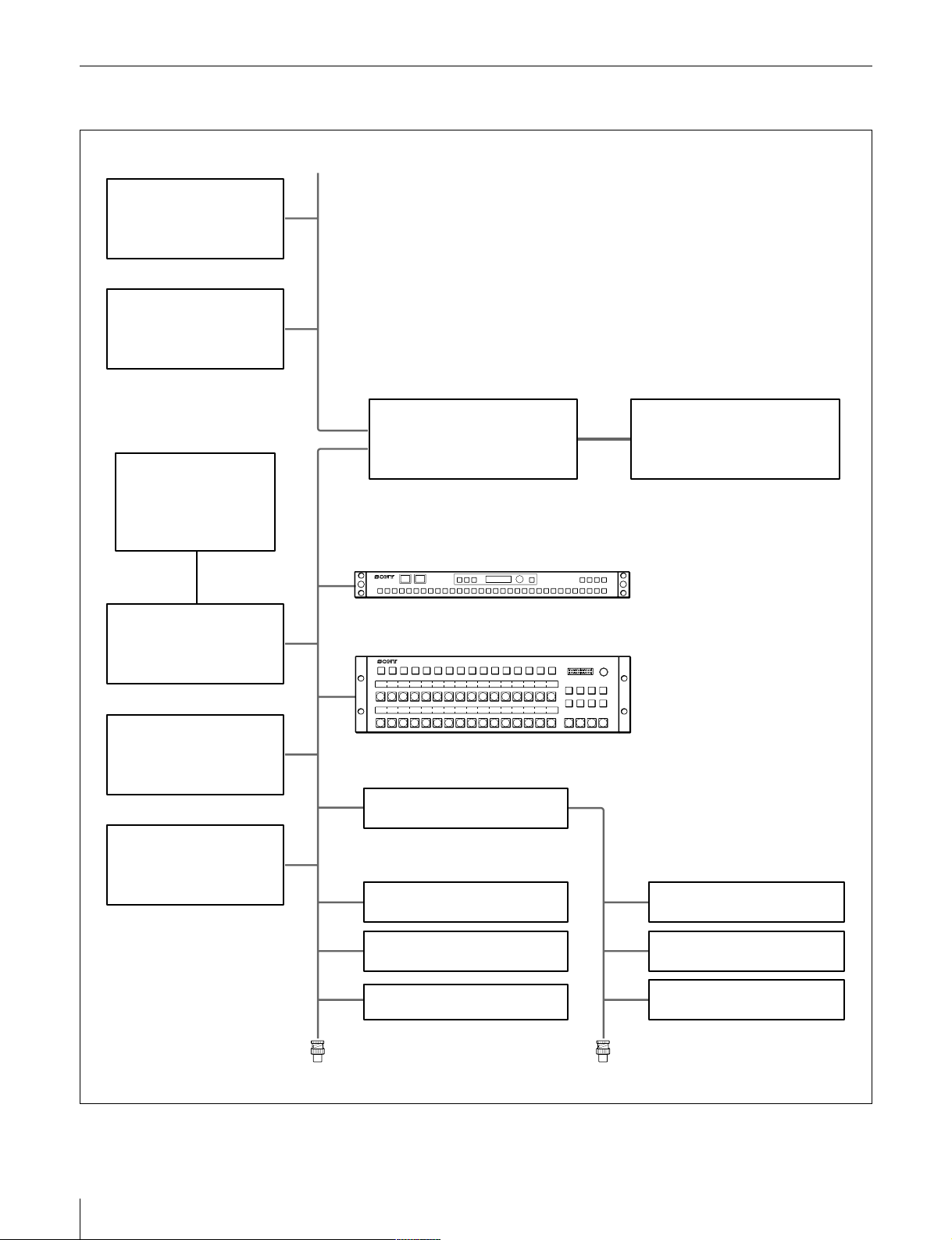
System Connection Example
MVS-8000
Multi Format Switcher
Processor
PFV-SP3300
Signal Processing Unit
Computer with the
terminal software installed
(for setup)
RS-232C
(D-sub 9-pin)
PFV-D10 + BKPF-R70A
S-BUS primary station
HDS-X5800
Router Processor
PFV-SP3300
Signal Processing Unit
(100Base-TX)
MKS-8010
System Control Unit
S-BUS (BNC) Control LAN
12345678910111213141516171819202122
AUX Bus Remote Panel
1 2 3 4 5 6 7 8 910111213141516
1 2 3 4 5 6 7 8 9 10 11 12 13 14 15 16
17 18 19 20 21 22 23 24 25 26 27 28 29 30 31 32
AUX Bus Remote Panel
BKPF-R70A + BZR-IF310
S-BUS sub-net controller
BKS-R-series
Remote Control Panel
KEY X-HOLD DEST M/E 1 M/E 2 M/E 3 P/P
ASSIGN
23 24 25 26 27 28 29 30 31 32
AUX BUS REMOTE PANEL MKS-8080
MKS-8080
AUX BUS REMOTE PANEL MKS-8082
ASGN DEST LEVEL RTR
XPT
LOCK
KEY
HOLD
(CHOP)
M/E1M/E2M/E
3
MKS-8082
CCP-8000 series
Center Control Panel
SELECTOR
CLEAR
P/P
BKS-R-series
Remote Control Panel
6
Overview
75Ω terminator
BKS-R-series
Remote Control Panel
BKS-R-series
Remote Control Panel
BKS-R-series
Remote Control Panel
BKS-R-series
Remote Control Panel
75Ω terminator
Location and Function of Parts
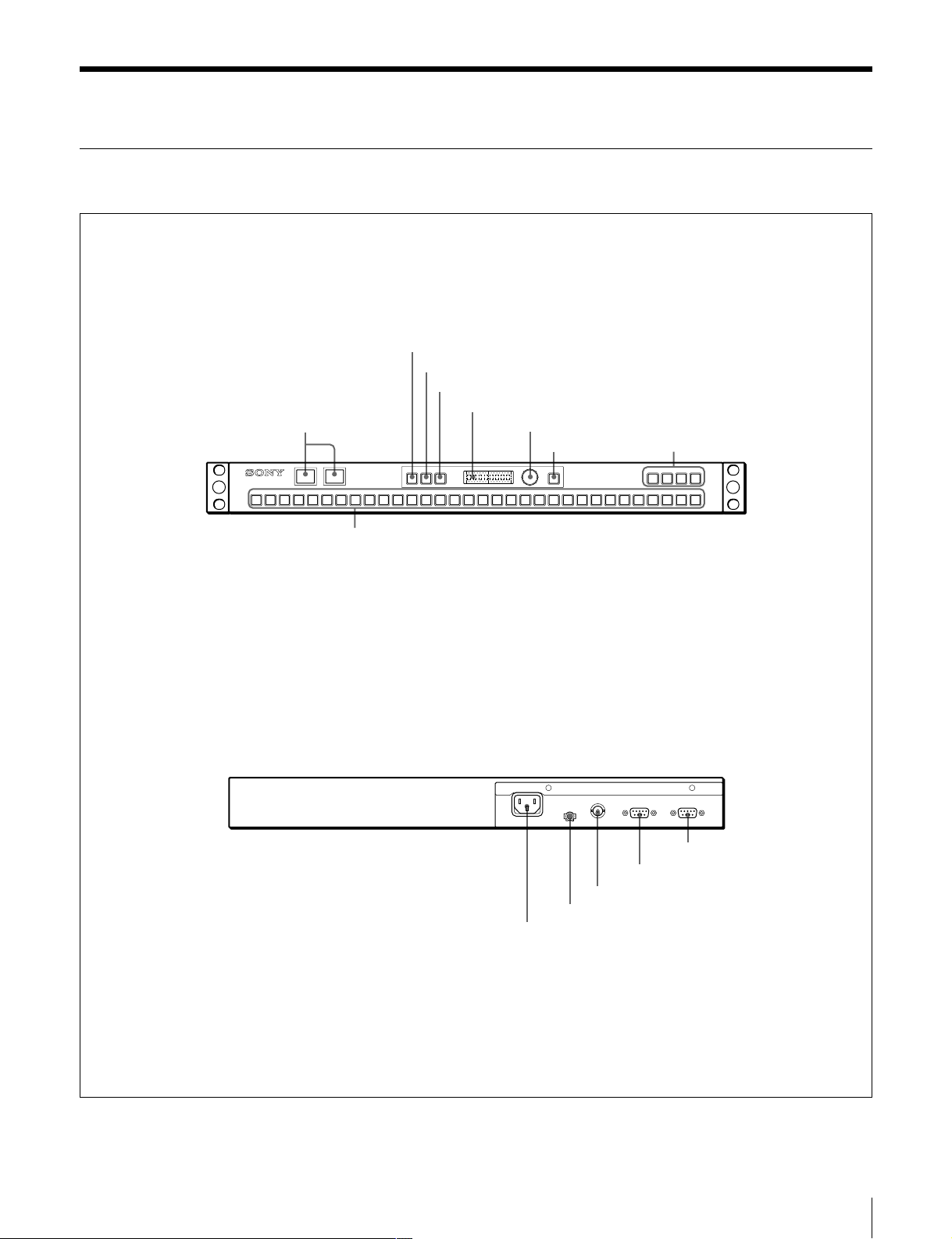
MKS-8080 Parts
Front panel
bKEY button
cX-HOLD button
dDEST button
ePreset display window
aTally lamps
KEY X-HOLD DEST M/E 1 M/E 2 M/E 3 P/P
12345678910111213141516171819202122
iSource select buttons
fSelector knob
gASSIGN button
ASSIGN
23 24 25 26 27 28 29 30 31 32
AUX BUS REMOTE PANEL MKS-8080
hReentry buttons
Rear panel
REMOTE 1
-AC IN
U
cREMOTE 1 connector
bGround terminal
a~ AC IN connector
REMOTE 2
RS-232C
eREMOTE 2 connector
dRS-232C connector
Location and Functio n of Parts
7
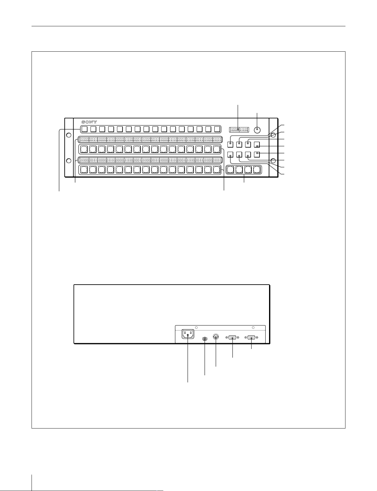
MKS-8082 Parts
Front panel
5 Preset display window
6 SELECTOR knob
12345678910111213141516
12345678910111213141516
17 18 19 20 21 22 23 24 25 26 27 28 29 30 31 32
qa Source display windows
0 Destination select buttons
Rear panel
AUX BUS REMOTE PANEL MKS-8082
SELECTOR
ASGN DEST LEVEL RTR
XPT
LOCK
KEY
M/E1M/E2M/E
CLEAR
HOLD
(CHOP)
P/P
3
8 Reentry buttons
9 Source select buttons
7 ASGN button
4 DEST button
qs LEVEL button
qd RTR button
qf CLEAR button
qg LOCK (CHOP) button
3 XPT HOLD button
2 KEY button
8
Location and Function of Parts
REMOTE 1
-AC IN
U
cREMOTE 1 connector
bGround terminal
a~ AC IN connector
REMOTE 2
RS-232C
eREMOTE 2 connector
dRS-232C connector

Functions of the Parts on the Front
Panel
a TALLY lamps (MKS-8080)
When the tally function is activated for one or more tally
groups, the tally status of the source selected for the
destination to be controlled is indicated.
For details on the tally setting, see “Menu Item Y: SET
DISPLAY MODES” on page 29.
e Preset display window
Shows the destination to be controlled in normal
operations. When an error is generated, an error message
appears. When you turn the SELECTOR knob, the name
selected with the knob is displayed for about 30 seconds.
This shows the status in up to eight characters according to
the operation mode and display format.
The display format can be set independently from the
terminal. For setting from the terminal, see “Menu Item
Y: SET DISPLAY MODES” on page 29.
b KEY button
Selects a source signal in AUX mode: VIDEO or KEY.
When the button is not lit, VIDEO is selected, and when
the button is lit, KEY is selected.
c X-HOLD (crosspoint ho ld) button (MKS-8080),
XPT HOLD (crosspoint hold) button (MKS-8082)
In AUX mode (RTR button not lit)
Press to light the button in green, and the crosspoint hold
function is enabled. Even i f snapsh ot is p er for med on t he
MVS-8000, the button assignment will not change linked
with the snapshot operation.
In RTR mode (RTR button lit) (MKS -8082 only)
Press to light the butt on in green, and the destin ation is
protected. You cannot switch the input signals with the
source select buttons. In a system using multiple control
units, the XPT HOLD buttons on all the units that sele ct
the same destination will be lit, and the source select
buttons on those units will be disabled.
If the selected destination is protected on another station,
the button lights in r ed. If y ou pr e ss th is b ut ton , t he I D of
the station will be displayed.
To release the crosspoint hold/protect setting
You can release it by either of the following methods:
• Pressing the X-HOLD/XPT HOLD button on the control
unit which has set the crosspoint hold/protect to make
the button go dark.
• Release from the terminal connected to the primary
station.
Note
You can set how the crosspoint hold/protect function
operates when the X-HOLD/XPT HOLD button is
pressed, by using PROTECT MODE in Menu Z.
For details, see “Menu It em Z: SE T PANEL S TATU S” on
page 30.
d DEST (destinatio n) button
Sets the displayed item on the preset display window when
you turn the SELECTOR knob. When the button is not lit,
the source name is displayed, and when the button is lit , the
destination name is displayed.
In AUX mode
When you turn the SELECTOR knob, the source name
appears in the left half of the window, and the button
number in the right half.
In RTR mode
The displayed contents vary depending on the display
format, as shown below.
1:NORMAL
There are two display formats according to the setting of
primary station menu item “J: NAME STYLE.”
TYPE+NUM (type name + number): The type na me and
a number (total of seven charac ters) of the d estina tion
and that of the source are displayed.
DESCRIP. NAME: All eight characters in the window
are used to show a descript ion of a sign al. For a signa l
for which no description has been specif i ed, th e Typ e
+ Number name is displayed.
2:2+2CHAR
The destination and source to be controlled are displayed
using four characters among the descriptions of the
corresponding signals. The ab breviation of a description is
obtained according to the format o f Sony-made production
switchers, which uses the first two and last two characters
of a description.
3:4CHAR
The destination and source to be controlled are displayed
using the first four characters among the descriptions of
the corresponding signals. In the left half of the window,
the source name is displayed in source mode, and the
destination name in destination mode .
If you have assigned the TAKE function to a button on
Menu N, normally the current inpu t operation is displayed ,
and when you press the button, the source selected last for
the destination currently controlled appears.
For details, see “Menu Item N: SET PANEL TABLE (for
Router mode)” on page 23.
Location and Functio n of Parts
9

f SELECTOR knob
Turning the knob shows the destination name in the preset
display window when the DEST button is lit, and the
source name when the button is not lit.
When you turn the knob while holding the ASSIGN/
ASGN button pressed, type names appear in the preset
display window one by one. If you release the ASSIGN/
ASGN button and turn the knob, the names classified
under the type name appear one by one in the preset
window.
You can limit the selectable range of names from the
terminal, as described below.
• A source on which secret has been set will be skipped.
• The selectable range is limited according to the available
source/destination table.
g ASSIGN button (MKS-8080), ASGN (assign)
button (MKS-8082)
The ASSIGN/ASGN butto n has the following two
functions:
To change the settings for the source select buttons and
reentry buttons
In RTR mode pressing a source select button or reentry
button while holding the ASSIGN/ASGN button pressed
assigns the source name displayed in the preset display
window to the pressed button.
In AUX mode, pressing a source select button or reentry
button while holding the ASSIGN/ASGN button pressed
assigns the source name displayed in the preset display
window to the pressed button, repl acing th e original name.
Normally, buttons 1 to 32 are set as source select buttons,
and buttons 121 to 124 are as reentry buttons. When the
SHIFT function is used, b ut ton s 33 to 64 are set as source
select buttons, and the buttons 125 to 128 as reentry
buttons.
To select by type
When you turn the SELECTOR knob while holding the
ASSIGN/ASGN button pressed, type name (TYPE)
appears in the preset display wi ndow. When the name you
wish to select appears, release the ASSIGN/ASGN butt on
and turn the SELECTOR kno b. The source or desti nati on
of the selected type will appear. You can easily select a
signal by classifying them using the type name.
h Reentry button
Selects a reentry input signal.
i Source select buttons
Select the source assigned to a button.
In AUX mode, source selection is linked with the MVS8000, but while the X-HOLD/XPT HOLD button is lit, the
current status is retained .
Signals are assigned to the buttons with the assign
operation or from the terminal. Once the signals are
assigned, the settings are held even if the power is turned
off, and each button functions according what you have
assigned it to do.
Level-select mode (LEVEL button lit) (MKS-8082
only)
The buttons indicate t he level s that can be co ntrolled from
this unit. The levels to be contro lled can be set from the
terminal.
The button for the level being selected lights in bright
green. Buttons for cont roll able bu t unsel ected levels ligh t
in amber if the levels have been specified on the primary
station. Buttons for the levels that have not been specified
on the primary station do not light.
The default level is displayed when the power is turned on,
when the destination is changed, or when the current level
is cleared. (If the default is “0,” the display is achieved
using the level table of the primary station.)
j Destinatio n select buttons (MKS-8082 only)
Select the destination assigned to a button.
k Source display windows (MKS-8082 only)
Show the source name assigned to the corresponding
source select button. The expanded input appears in the
window corresponding to the button for which expansion
input has been assigned by the routing function.
l LEVEL button (MKS-8082 only)
Press to light the button, and the unit enters the levelselection mode. In level-selection mode, eight source
select buttons show the levels selectable on this unit.
m RTR button (MKS-8082 only)
Selects the operation mode, AUX or RTR. When the
button is not lit, the unit is in AUX mode, and when the
button is lit, the unit is in RTR mode.
n CLEAR button (MKS-8082 only)
Press this button in the following cases:
• To cancel the operation being performed
• To return to the status set from the terminal after setting
the levels using the le vel select button on this uni t
• To clear an error message displayed in the preset display
window
o LOCK (CHOP) button (MKS-8082 only)
This button has two functions: lock function and chop
function.
Lock function
Press to light this button in red, and the buttons on the front
panel other than this bu tton will be disabled. Th is prevents
switching by touching the select buttons accidentally.
If you press a select button while the LOCK (CHOP)
button is lit in red, the following message appears in the
preset display window.
<<<<LOCK mode>>>>CSUMxxxxID=xxxVer.1.00
“CSUM” means the ROM checksum, and “xxx” is the
station number of this unit.
10
Location and Function of Parts

If you press the button while it is lit in red, the button goes
dark, and the lock is released.
CHOP function
When you hold the butt on pressed for abo ut 3 seconds, the
button lights in green, and the chop mode is obtained. In
chop mode, the source before the chop mode and a source
selected in chop mode are switched alternately at a
specified interval.
In chop mode, CHOP appears in the preset display
window, and turning the SELECTOR knob changes the
interval for toggling between the two signals.
Functions of the Parts on the Rear
Panel
a -AC IN (AC power input) connector
Connect to an AC power source using the designated AC
power cord.
b Ground terminal
For signal grounding.
c REMOTE 1 connector (BNC type)
Connect to the S-BUS line using the T-bridge (supplied)
and a 75-ohm coaxial cable (BELDEN 8281 or
equivalent).
d RS-232C connector (D-sub 9-pin)
For servicing. Connect via an RS-232C cable to a
computer for downloading software and monitoring
communication status.
e REMOTE 2 connector (D-sub 9-pin)
For RS-422A remote control.
Location and Functio n of Parts
11
Preparations
Settings on the Control Terminal
Before switching signals with this unit, the following
preparations should be made on t he t erminal co nnec ted t o
the primary station of the S-BUS data lin k.
1
Set the type names of sources, such as VTR, FLM,
AUX, etc.
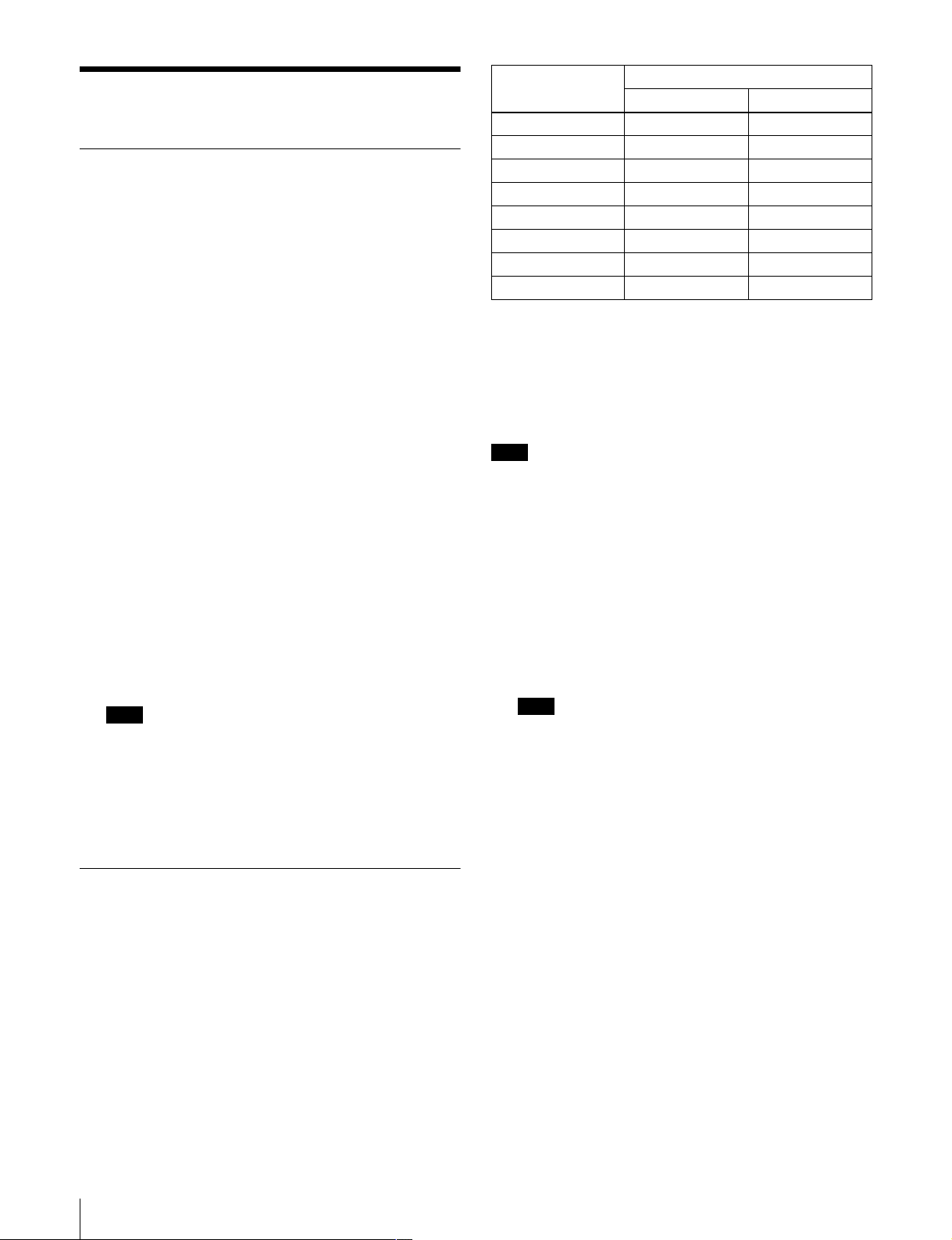
Button No. Input value
Unlit Lit
Button [1] 01
Button [2] 02
Button [3] 04
Button [4] 08
Button [5] 016
Button [6] 032
Button [7] 064
Button [8] 0 128
Up to 32 type names may be set.
2
Set the source names using a type name and number,
such as FLM34.
The list of registered source names is called the source
table.
3
Set the destination names using a type name and
number, such as VTR089.
The list of registered destination names is called the
destination table.
4
Set the level to be controlled for each destination.
5
Set the station number of this unit (see “Setting the
station number”).
6
Set the specified station to an active unit.
Note
If the station is not activated even when it is connec ted
to an active S-BUS data li nk, switc hing of crossp oints
cannot be made, while destination selection and
crosspoint display are enabled.
Example:
If buttons [1], [2] and [4] are lit, the station number is 11
(1 + 2 + 8).
For the button numbers, see “Making the Settings With
Buttons (Setup Function)” on page 15.
Note
Do not assign the same number to more than one uni t
connected to a routing switcher.
1
Press and hold the X-HOLD/XPT HOLD button and
LOCK (CHOP) or KEY button together for about 5
seconds until “Reset” appears in the preset display
window to restart the unit (so f twa r e reset).
2
During restarting (lighting statuses of the buttons are
being checked), press and hold source select buttons
[1], [2], [3], and [4] to ente r sta tion number setting
mode.
Note
When the power is turned ON for the first time, station
number setting mode is automatically set, and steps 1
and 2 are not required.
3
Press the appropriate source select buttons.
7
Setup the global phantom, etc. as required.
Preparations for the MKS-8080/8082
You may use up to 253 control u nits, includin g this unit, in
combination to expand the number of sources and
destinations, or use this unit alone.
Setting the station number
Set the station number using the source/destination select
buttons [1] to [8]. The station number is obtained by
adding the binary place values of the buttons that are lit.
12
Preparations
The ID number will appear in the Preset display
window in the format ID = xxx.
4
Press the ASSIGN/ASGN button.
The set station number is registered.
The registered station number is held even if the power
is turned off.
 Loading...