

Sony CCP-6224, CCP-6324, MKS-8010B, MKS-8011A, MKS-8013A Operation Manual
...
CENTER CONTROL PANEL PACK
CCP-6000/8000
CCP-6224 CCP-6324 MKS-8010B MKS-8011A
MKS-8013A MKS-8014A MKS-8015A MKS-8017A
MKS-8018A MKS-8019A MKS-8020A MKS-8021A
MKS-8021ASC MKS-8022A MKS-8022ASC MKS-8023AB
MKS-8024A MKS-8025MS MKS-8026A MKS-8027A
MKS-8028A MKS-8030A MKS-8031AJS MKS-8031ATB
MKS-8032A MKS-8033A MKS-8034ADK MKS-8034AFB
MKS-8035A MKS-8036A MKS-8040 MKS-8041
MKS-8042 MKS-8075A MKS-8076 HK-PSU02
OPERATION MANUAL [English]
3rd Edition (Revised 1)
3206011220

WARNING
To reduce the risk of fire or electric shock,
do not expose this apparatus to rain or
moisture.
generates, uses, and can radiate radio frequency energy and,
if not installed and used in accordance with the instruction
manual, may cause harmful interference to radio
communications. Operation of this equipment in a residential
area is likely to cause harmful interference in which case the
user will be required to correct the interference at his own
expense.
To avoid electrical shock, do not open the
cabinet. Refer servicing to qualified
personnel only.
THIS APPARATUS MUST BE EARTHED.
AVERTISSEMENT
Afin de réduire les risques d’incendie ou
d’électrocution, ne pas exposer cet
appareil à la pluie ou à l’humidité.
Afin d’écarter tout risque d’électrocution,
garder le coffret fermé. Ne confier
l’entretien de l’appareil qu’à un personnel
qualifié.
CET APPAREIL DOIT ÊTRE RELIÉ À LA
TERRE.
You are cautioned that any changes or modifications not
expressly approved in this manual could void your authority to
operate this equipment.
All interface cables used to connect peripherals must be
shielded in order to comply with the limits for a digital device
pursuant to Subpart B of Part 15 of FCC Rules.
This device complies with Part 15 of the FCC Rules. Operation
is subject to the following two conditions: (1) this device may
not cause harmful interference, and (2) this device must
accept any interference received, including interference that
may cause undesired operation.
For the customers in Canada
This Class A digital apparatus complies with Canadian ICES-
003.
Pour les clients au Canada
Cet appareil numérique de la classe A est conforme à la
norme NMB-003 du Canada.
This symbol is intended to alert the user to the
presence of important operating and
maintenance (servicing) instructions in the
literature accompanying the appliance.
WARNUNG
Um die Gefahr von Bränden oder
elektrischen Schlägen zu verringern, darf
dieses Gerät nicht Regen oder Feuchtigkeit
ausgesetzt werden.
Um einen elektrischen Schlag zu
vermeiden, darf das Gehäuse nicht
geöffnet werden. Überlassen Sie
Wartungsarbeiten stets nur qualifiziertem
Fachpersonal.
DIESES GERÄT MUSS GEERDET
WERDEN.
For the customers in the USA
This equipment has been tested and found to comply with the
limits for a Class A digital device, pursuant to Part 15 of the
FCC Rules. These limits are designed to provide reasonable
protection against harmful interference when the equipment is
operated in a commercial environment. This equipment
WARNING: THIS WARNING IS APPLICABLE FOR USA
ONLY.
If used in USA, use the UL LISTED power cord specified
below.
DO NOT USE ANY OTHER POWER CORD.
Plug Cap Parallel blade with ground pin
(NEMA 5-15P Configuration)
Cord Type SJT, three 16 or 18 AWG wires
Length Minimum 1.5m (4 ft .11in.), Less than 2.5 m
(8 ft .3 in.)
Rating Minimum 10A, 125V
Using this unit at a voltage other than 120V may require the
use of a different line cord or attachment plug, or both. To
reduce the risk of fire or electric shock, refer servicing to
qualified service personnel.
WARNING: THIS WARNING IS APPLICABLE FOR OTHER
COUNTRIES.
1.Use the approved Power Cord (3-core mains lead) /
Appliance Connector / Plug with earthing-contacts that
conforms to the safety regulations of each country if
applicable.
2.Use the Power Cord (3-core mains lead) / Appliance
Connector / Plug conforming to the proper ratings (Voltage,
Ampere).
2

If you have questions on the use of the above Power Cord /
Appliance Connector / Plug, please consult a qualified service
personnel.
AVERTISSEMENT
1.Utilisez un cordon d’alimentation (câble secteur à 3 fils)/
fiche femelle/fiche mâle avec des contacts de mise à la terre
conformes à la réglementation de sécurité locale applicable.
2.Utilisez un cordon d’alimentation (câble secteur à 3 fils)/
fiche femelle/fiche mâle avec des caractéristiques
nominales (tension, ampérage) appropriées.
Pour toute question sur l’utilisation du cordon d’alimentation/
fiche femelle/fiche mâle ci-dessus, consultez un technicien du
service après-vente qualifié.
WARNUNG
1.Verwenden Sie ein geprüftes Netzkabel (3-adriges
Stromkabel)/einen geprüften Geräteanschluss/einen
geprüften Stecker mit Schutzkontakten entsprechend den
Sicherheitsvorschriften, die im betreffenden Land gelten.
2.Verwenden Sie ein Netzkabel (3-adriges Stromkabel)/einen
Geräteanschluss/einen Stecker mit den geeigneten
Anschlusswerten (Volt, Ampere).
Wenn Sie Fragen zur Verwendung von Netzkabel/
Geräteanschluss/Stecker haben, wenden Sie sich bitte an
qualifiziertes Kundendienstpersonal.
For the customers in Europe (Except for MKS-8042)
This product with the CE marking complies with the EMC
Directive issued by the Commission of the European
Community.
Compliance with this directive implies conformity to the
following European standards:
• EN55103-1: Electromagnetic Interference (Emission)
• EN55103-2: Electromagnetic Susceptibility (Immunity)
This product is intended for use in the following
Electromagnetic Environment: E4 (controlled EMC
environment, ex. TV studio).
Pour les clients en Europe (hormis MKS-8042)
Ce produit portant la marque CE est conforme à la Directive
sur la compatibilité électromagnétique (EMC) émise par la
Commission de la Communauté européenne.
La conformité à cette directive implique la conformité aux
normes européennes suivantes:
• EN55103-1 : Interférences électromagnétiques (émission)
• EN55103-2 : Sensibilité électromagnétique (immunité)
Ce produit est prévu pour être utilisé dans l’environnement
électromagnétique suivant: E4 (environnement EMC contrôlé,
ex. studio de télévision).
Für Kunden in Europa (ohne MKS-8042)
Dieses Produkt besitzt die CE-Kennzeichnung und erfüllt die
EMV-Richtlinie der EG-Kommission.
Angewandte Normen:
• EN55103-1: Elektromagnetische Verträglichkeit
(Störaussendung)
• EN55103-2: Elektromagnetische Verträglichkeit
(Störfestigkeit
Für die folgende elektromagnetische Umgebung: E4
(kontrollierter EMV-Bereich, z.B. Fernsehstudio).
For the customers in Europe, Australia and New Zealand
WARNING
This is a Class A product. In a domestic environment, this
product may cause radio interference in which case the user
may be required to take adequate measures.
Pour les clients en Europe, Australie et Nouvelle-Zélande
AVERTISSEMENT
Il s’agit d’un produit de Classe A. Dans un environnement
domestique, cet appareil peut provoquer des interférences
radio, dans ce cas l’utilisateur peut être amené à prendre des
mesures appropriées.
Für Kunden in Europa, Australien und Neuseeland
WARNUNG
Dies ist eine Einrichtung, welche die Funk-Entstörung nach
Klasse A besitzt. Diese Einrichtung kann im Wohnbereich
Funkstörungen verursachen; in diesem Fall kann vom
Betreiber verlangt werden, angemessene Maßnahmen
durchzuführen und dafür aufzukommen.
For the customers in Europe
The manufacturer of this product is Sony Corporation, 1-7-1
Konan, Minato-ku, Tokyo, Japan.
The Authorized Representative for EMC and product safety is
Sony Deutschland GmbH, Hedelfinger Strasse 61, 70327
Stuttgart, Germany.
This apparatus shall not be used in the residential area.
Pour les clients en Europe
Le fabricant de ce produit est Sony Corporation, 1-7-1 Konan,
Minato-ku, Tokyo, Japon.
Le représentant autorisé pour EMC et la sécurité des produits
est Sony Deutschland GmbH, Hedelfinger Strasse 61, 70327
Stuttgart, Allemagne.
Ne pas utiliser cet appareil dans une zone résidentielle.
Für Kunden in Europa
Der Hersteller dieses Produkts ist Sony Corporation, 1-7-1
Konan, Minato-ku, Tokyo, Japan.
Der autorisierte Repräsentant für EMV und Produktsicherheit
ist Sony Deutschland GmbH, Hedelfinger Strasse 61, 70327
Stuttgart, Deutschland.
Dieser Apparat darf nicht im Wohnbereich verwendet werden.
Periodic inspections
To guarantee safe long-term operation, periodic inspections
are recommended. Please contact your Sony representative
for detailed information about the content and cost of periodic
inspections.
3

For the customers in Taiwan only (MKS-8010B only)
For the customers in the USA (MKS-8011A only)
Lamp in this product contains mercury. Disposal of these
materials may be regulated due to environmental
considerations. For disposal or recycling information, please
contact your local authorities or the Electronic Industries
Alliance (www.eiae.org).
Pour les clients aux Etats-Unis (MKS-8011A uniquement)
La lampe dans ce produit contient du mercure. La disposition
de ces matériaux peut être réglementée suite à des
considérations environnementales. Pour obtenir des
informations de disposition ou de recyclage, veuillez
communiquer avec vos autorités locales ou la
Telecommunications Industry Association (www.eiae.org).
For the State of California, USA only (MKS-8010B only)
Perchlorate Material - special handling may apply, See
www.dtsc.ca.gov/hazardouswaste/perchlorate
Perchlorate Material : Lithium battery contains perchlorate.
4

Table of Contents
Overview ............................................................................... 7
Features......................................................................................7
Units and Modules..................................................................... 7
Optional Accessories ................................................................. 9
Location and Function of Parts.........................................10
MKS-8010B Front Panel ........................................................ 10
MKS-8010B Rear Panel ......................................................... 11
MKS-8011A Menu Panel ....................................................... 13
Main Panel .............................................................................. 13
AUX Panel.............................................................................. 14
MKS-8025MS “Memory Stick”/USB Module....................... 14
MKS-8075A Extension Adaptor ............................................ 15
MKS-8076 Memory Card/USB Adaptor................................ 15
Example System Configuration ........................................16
MVS/DVS System Configuration .......................................... 16
Center Control Panel Connection ........................................... 17
Exchanging Button Labels ................................................19
Adjusting Fader Torque..................................................... 19
Power Supply Unit Status Indicators................................ 20
Care of the Control Panel ..................................................20
About “Memory Stick” ....................................................... 21
Specifications..................................................................... 22
Center Control Panel................................................................22
Main Panel ............................................................................... 23
AUX panel ...............................................................................23
MKS-8010B System Control Unit...........................................23
MKS-8011A Menu Panel ........................................................24
CCP-6224 2M/E Control Panel ...............................................25
CCP-6324 3M/E Control Panel ...............................................25
MKS-8013A 32 AUX Bus Module .........................................25
MKS-8014A 24 AUX Bus Module .........................................25
MKS-8015A 16 AUX Bus Module .........................................25
MKS-8017A 32 XPT Module .................................................25
MKS-8018A 24 XPT Module .................................................25
MKS-8019A 16 XPT Module .................................................25
MKS-8020A Standard Transition Module .............................. 26
MKS-8021A Simple Transition Right Module ....................... 26
MKS-8021ASC Simple Transition Compact Right Module... 26
MKS-8022A Simple Transition Left Module..........................26
MKS-8022ASC Simple Transition Compact Left Module .....26
MKS-8023AB Compact Key Transition Module.................... 26
MKS-8024A Flexi Pad Module............................................... 26
Table of Contents
5

MKS-8025MS “Memory Stick”/USB Module........................ 27
MKS-8026A 10 Key Pad Module ...........................................27
MKS-8027A Compact Transition Right Module ....................27
MKS-8028A Compact Transition Left Module ......................27
MKS-8030A Key Frame Module ............................................27
MKS-8031AJS Joystick Module .............................................27
MKS-8031ATB Track Ball Module........................................ 27
MKS-8032A DSK Fader Module............................................ 28
MKS-8033A Utility/Shotbox Module .....................................28
MKS-8034ADK DSK/FTB Module........................................28
MKS-8034AFB FTB Module.................................................. 28
MKS-8035A Key Control Module ..........................................28
MKS-8036A Device Control Module .....................................28
MKS-8040 Blank Panel (1/3) ..................................................28
MKS-8041 Blank Panel (1/2) ..................................................28
MKS-8042 Blank Panel (1/6) ..................................................29
MKS-8075A Extension Adaptor .............................................29
MKS-8076 Memory Card/USB Adaptor.................................29
HK-PSU02 Power Supply Unit ............................................... 29
6
Table of Contents

Overview
The CCP-6000/8000 Center Control Panel Pack provides
control panels for operation of the MVS-6000/8000 Multi
Format Switcher system and their peripheral devices. It
has a wide range of application, being usable in studios and
the ENG and OB vans of large-scale live production
systems as well as in postproduction editing systems.
“CCP-6000/8000 Center Control Panel” is a generic name
of the control panels which are comprised of the following
three components.
graphics for registered patterns. Registered effects are
evident at a glance, a significant advantage in live
situations where decisions must be made instantly. The
menu control block features a large, touch-sensitive LCD
panel for speedy menu operations.
Special features for mid- and large-scale
live switcher systems
The center control panel was designed with many features
for live operation, such as shotbox functions, source name
display on cross-point buttons, the ability to recall
snapshots and other effect memory settings directly on the
Flexi Pad
TM
, and redundant power supply.
Main Panel
The main panel, comprised of various types of operation
modules, provides the operating controls of the system.
The CCP-8000 can be flexibly comprised by choosing the
numbers of M/E banks (2 to 4) and cross-point buttons (16,
24 or 32) and adding the auxiliary bus module. (The layout
of the CCP-6000 is fixed.)
The auxiliary bus module can also be removed from the
main panel and used as an AUX panel.
Operation modules can be mounted in the MKS-8075A
Extension Adaptor and MKS-8076 Memory Card/USB
Adaptor for installation apart from the main panel.
Menu Panel
The menu panel provides a GUI interface for making
system settings.
System Control Unit
The system control unit provides control functions for the
center control panel as a whole. It also supplies power to
the various panels.
In this manual, CCP-6000 is distinguished from
CCP-8000. CCP-6000 indicates the control panels
including CCP-6224 or CCP-6324, and the other control
panels are referred as CCP-8000.
Features
Powerful external device control
The center control panel can control devices such as Sony
routing switchers and IF processors. Control of devices
such as VTRs and DDRs can be linked to timelines of
switchers and DME.
Generous storage capacity
The center control panel has an internal hard disk drive for
storage of settings and still pictures from switcher frame
memory. They can also be storage to “Memory Sticks” and
other memory cards.
Units and Modules
CCP-6224 2M/E Control Panel
This is a 2M/E control panel equipped with 24 columns of
cross-point buttons.
CCP-6324 3M/E Control Panel
This is a 3M/E control panel equipped with 24 columns of
cross-point buttons.
MKS-8010B System Control Unit
A system control unit to provide control functions for the
center control panel as a whole and supply power to the
various panels.
Free control panel layout (CCP-8000)
The modular configuration of the center control panel
allows operation modules to be freely laid out in the way
that best meets your requirements.
Intuitive, easy-to-use man-machine
interface
The Flexi PadTM and shotbox sections feature LCD display
buttons that can display the names of registered effects or
MKS-8011A Menu Panel
A menu operation panel equipped with a 10.4-inch color
LCD touch screen.
MKS-8013A 32 AUX Bus Module
An auxiliary bus control module with 32 cross-point
buttons.
Overview
7

MKS-8014A 24 AUX Bus Module
An auxiliary bus control module with 24 cross-point
buttons.
MKS-8015A 16 AUX Bus Module
An auxiliary bus control module with 16 cross-point
buttons.
section with a split fader and a Flexi Pad section. The fader
lever is at a different position than on the MKS-8021ASC.
MKS-8023AB Compact Key Transition
Module
A key transition operation module for 2/4-keyer
transitions. Used in combination with the MKS-8021A/
8021ASC/8022A/8022ASC.
MKS-8017A 32 XPT Module
An M/E or PGM/PST bank cross-point module with 32
cross-point buttons.
MKS-8018A 24 XPT Module
An M/E or PGM/PST bank cross-point module with 24
cross-point buttons.
MKS-8019A 16 XPT Module
An M/E or PGM/PST bank cross-point module with 16
cross-point buttons.
MKS-8020A Standard Transition Module
A transition operation module for an M/E bank or the
PGM/PST bank. Comprised of a transition operation
section and a key transition operation section.
MKS-8021A Simple Transition Right
Module
A transition operation module for an M/E bank or the
PGM/PST bank. Comprised of a transition operation
section with a split fader and a Flexi Pad section. The fader
lever is at a different position than on the MKS-8022A.
MKS-8021ASC Simple Transition Compact
Right Module
A transition operation module for an M/E bank or the
PGM/PST bank. Comprised of a transition operation
section with a split fader and a Flexi Pad section. The fader
lever is at a different position than on the MKS-8022ASC.
MKS-8024A Flexi Pad Module
An operation module for Flexi Pad operations. Used in
combination with the MKS-8020A.
MKS-8025MS “Memory Stick”/USB Module
A module equipped with a “Memory Stick” slot and three
DEVICE connectors.
MKS-8026A 10 Key Pad Module
A numeric keypad module.
MKS-8027A Compact Transition Right
Module
A transition operation module for an M/E bank or the
PGM/PST bank. Features a simple key transition operation
section. A compact module that fits in 1/2 rack width.
MKS-8028A Compact Transition Left
Module
Identical to the MKS-8027A, but with the fader lever on
the left side.
MKS-8030A Key Frame Module
A module for key frame operations.
MKS-8031AJS Joystick Module
A module for DME operations using a joystick and for
switcher wipe positioner operations.
MKS-8022A Simple Transition Left Module
A transition operation module for an M/E bank or the
PGM/PST banks. Comprised of a transition operation
section with a split fader and a Flexi Pad section. The fader
lever is at a different position than on the MKS-8021A.
MKS-8022ASC Simple Transition Compact
Left Module
A transition operation module for an M/E bank or the
PGM/PST bank. Comprised of a transition operation
8
Overview
MKS-8031ATB Track Ball Module
A module for DME operations using a track ball and for
switcher wipe positioner operations.
MKS-8032A DSK Fader Module
An operation module for fader lever operations on four
downstream keys.
MKS-8033A Utility/Shotbox Module
An operation module to provide buttons that may be used
as utility buttons or shotbox recall buttons.

MKS-8034ADK DSK/FTB Module
An operation module for operations on two downstream
keys and for fade to black and preview selector operations.
(This module is the MKS-8034AFB module with the
addition of controls for DSK operations.)
MKS-8034AFB FTB Module
An operation module for fade to black and preview
selector operations.
MKS-8035A Key Control Module
An operation module for key adjustments and other
operations.
MKS-8036A Device Control Module
An operation module for disk recorder/VTR control
operations.
MKS-8040 Blank Panel (1/3)
A blank panel to fill parts of the main panel which are not
filled by the modules in its current configuration.
SWC-5005 50-pin Panel Cable (5 m/16 ft)
SWC-5010 50-pin Panel Cable (10 m/33 ft)
RMM-10 Rack Mount Kit
MKS-8041 Blank Panel (1/2)
A blank panel to fill parts of the main panel which are not
filled by the modules in its current configuration.
MKS-8042 Blank Panel (1/6)
A blank panel to fill parts of the main panel which are not
filled by the modules in its current configuration.
MKS-8075A Extension Adaptor
An adaptor which allows modules to be installed apart
from the main panel.
MKS-8076 Memory Card/USB Adaptor
An adaptor that allows the MKS-8025MS to be installed
apart from the main panel.
HK-PSU02 Power Supply Unit (on MKS8010B)
A backup power supply unit. The MKS-8010B is supplied
standard with one power unit. Installing an HK-PSU02
gives two power units.
This allows a backup system to be constructed which will
operate normally even if one of the power supply units
fails.
Optional Accessories
SWC-5002 50-pin Panel Cable (2 m/7 ft)
Overview
9
Location and Function of Parts
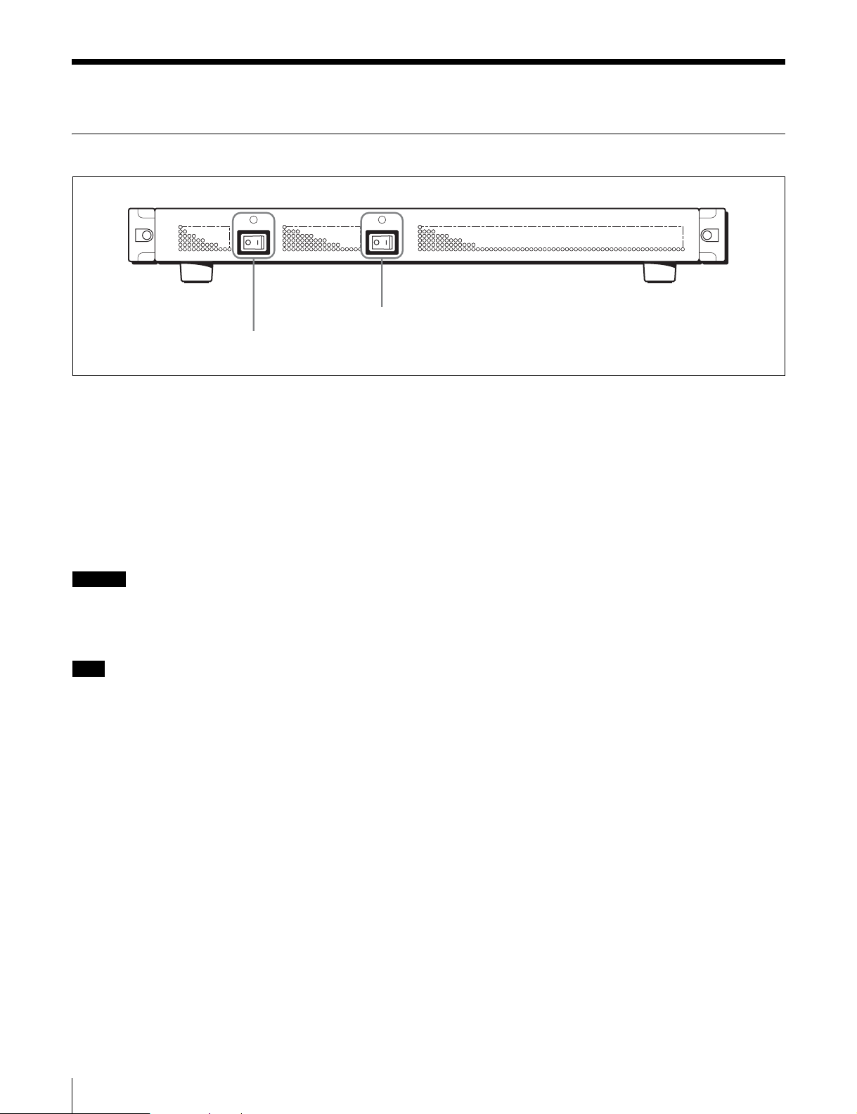
MKS-8010B Front Panel
POWER A POWER B
POWER B switch and status indicator
POWER A switch and status indicator
POWER A and B switches and status indicators
The POWER switches turn the unit on and off. The unit is
powered on when the POWER switches are on the “?” side,
and powered off when the POWER switches are on the
“a” side. The status indicators light in green when the unit
is powered on.
Depending on the configuration of your unit, an optional
Backup Power Supply Unit may not be installed. In this
case, there is no POWER B switch indicator.
Caution
Before installing an optional Backup Power Supply Unit in
your unit, be sure to contact your Sony service
representative.
Note
If a status indicator does not light when you turn a POWER
switch on, there may be a fault in the power circuits. Turn
the POWER switch off and contact your Sony service
representative.
10
Location and Function of Parts
 Loading...