

Sony Md Walkman MZ-R37 Service Manual
– 1 –
MICROFILM
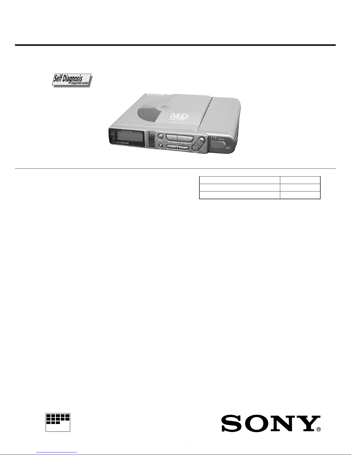
MZ-R37
SERVICE MANUAL
PORTABLE MINIDISC RECORDER
SPECIFICATIONS
US Model
Canadian Model
AEP Model
UK Model
E Model
Australian Model
Tourist Model
Model Name Using Similar Mechanism MZ-R55
MiniDisc Mechanism Type MT-MZR37-161
Optical Pick-up Type KMS-280A
US and foreign patents licensed from Dolby Laboratories
Licensing Corporation.
System
Audio playing system
MiniDisc digital audio system
Laser diode properties
Material: GaAlAs
Wavelength: λ = 780 nm
Emission duration: continuous
Laser output: less than 44.6 µW
(This output is the value measured at a
distance of 200 mm from the lens surface on
the optical pick-up block with 7 mm
aperture.)
Recording and playback time
Maximum 74 minutes (MDW-74, stereo
recording)
Maximum 148 minutes (MDW-74, monaural
recording)
Revolutions
400 rpm to 900 rpm (CLV)
Error correction
Advanced Cross Interleave Reed Solomon
Code (ACIRC)
Sampling frequency
44.1 kHz
Sampling rate converter
Input: 32 kHz / 44.1 kHz / 48 kHz
Coding
Adaptive TRansform Acoustic Coding (ATRAC)
Modulation system
EFM (Eight to Fourteen Modulation)
Number of channels
2 stereo channels
1 monaural channel
Frequency response
20 to 20,000 Hz ± 3 dB
Wow and Flutter
Below measurable limit
Inputs
MIC (PLUG IN POWER): stereo mini-jack,
0.35–1.38 mV
(OPTICAL) LINE IN: stereo mini-jack with
optical (digital) in
• Line in: 69–194 mV
• Optical (digital) in: wave length 660 nm
Outputs
PHONES/REMOTE: stereo mini-jack,
maximum output level 5 mW + 5 mW, load
impedance 16 ohm
LINE OUT: stereo mini-jack, 194 mV, load
impedance 10 kilohm or greater
General
Power requirements
Sony AC Power Adaptor (supplied)
connected at the DC IN 4.5 V jack:
120 V AC, 60 Hz (US, Canadian model)
220–230 V AC, 50/60 Hz (AEP model)
230–240 V AC, 50 Hz (UK model)
240 V AC, 50 Hz (Australian and New Zealand model)
Two nickel-cadmium rechar geable batteries
NC-AA (supplied)
Two LR6 (size AA) alkaline batteries (not supplied)
– Continued on next page –
Ver 1.3 1999. 11
With SUPPLEMENT-1
(9-926-952-81)
With SUPPLEMENT-2
(9-926-952-82)
– 2 –
Battery operation time
1)
Batteries Recording
2)
Playback
Two NC-AA Approx. Approx.
nickel-cadmium
3 hours 5 hours
rechargeable batteries
Two LR6 (size AA) ––––
3)
Approx.
Sony alkaline dry batteries 13 hours
1)
The battery life may be shorter due to
operating conditions and the temperature
of the location.
2)
When you record, use fully charged
rechargeable batteries.
3)
Recording time may differ according to the
alkaline batteries.
Dimensions
Approx. 116.8 × 18.5 × 86.1 mm (w/h/d)
(4 5/8 × 3/4 × 3 1/2 in.)
Mass
Approx. 160 g (5.6 oz) the recorder only
Approx. 220 g (7.8 oz) incl. a recordable MD,
and two NC-AA nickel-cadmium
rechargeable batteries
Supplied accessories
Optical cable (1) (MC-918)
AC power adaptor (1) (AC-MZR37)
Headphones with a remote control (1) (SZR-S17)
NC-AA nickel-cadmium rechargeable batteries (2)
Rechargeable battery carrying case (1)
Design and specifications are subject to change without notice.
SAFETY-RELATED COMPONENT WARNING!!
COMPONENTS IDENTIFIED BY MARK ! OR DOTTED LINE WITH
MARK ! ON THE SCHEMATIC DIAGRAMS AND IN THE PARTS
LIST ARE CRITICAL TO SAFE OPERATION.
REPLACE THESE COMPONENTS WITH SONY PARTS WHOSE
PART NUMBERS APPEAR AS SHOWN IN THIS MANUAL OR IN
SUPPLEMENTS PUBLISHED BY SONY.
Flexible Circuit Board Repairing
• Keep the temperature of the soldering iron around 270°C
during repairing.
• Do not touch the soldering iron on the same conductor of the
circuit board (within 3 times).
• Be careful not to apply force on the conductor when soldering
or unsoldering.
Notes on chip component replacement
• Never reuse a disconnected chip component.
• Notice that the minus side of a tantalum capacitor may be
damaged by heat.
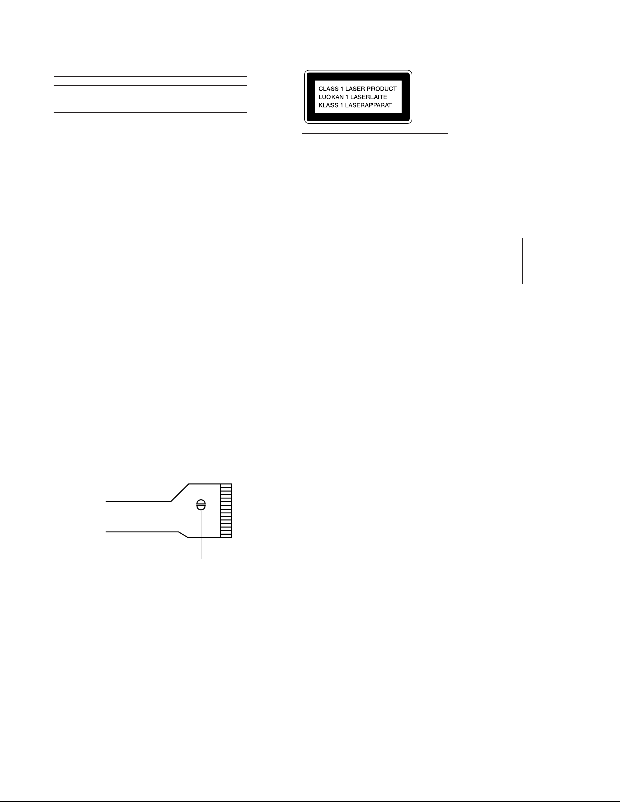
Precautions for Laser Diode Emission Check
When checking the emission of the laser diode during adjustments, never view directly downwards as this may lead to
blindness.
Precautions for Using Optical Pick-up (KMS-280A)
As the laser diode inside the optical pick-up damages by static
electricity easily, solder the laser tap of the Optical pick-up
flexible board when handling. Also take the necessary measures
to prevent damages by static electricity. Handle the Optical pickup flexible board with care as it breaks easily.
Laser tap
Optical Pick-up flexible board
ATTENTION AU COMPOSANT AYANT RAPPORT
À LA SÉCURITÉ!!
LES COMPOSANTS IDENTIFIÉS P AR UNE MARQUE ! SUR LES
DIAGRAMMES SCHÉMA TIQUES ET LA LISTE DES PIÈCES SONT
CRITIQUES POUR LA SÉCURITÉ DE FONCTIONNEMENT. NE
REMPLACER CES COMPOSANTS QUE PAR DES PIÈCES SONY
DONT LES NUMÉROS SONT DONNÉS DANS CE MANUEL OU
DANS LES SUPPLÉMENTS PUBLIÉS PAR SONY.
CAUTION
Use of controls or adjustments or performance of procedures
other than those specified herein may result in hazardous
radiation exposure.
IN NO EVENT SHALL SELLER BE
LIABLE FOR ANY DIRECT,
INCIDENTAL OR CONSEQUENTIAL
DAMAGES OF ANY NATURE, OR
LOSSES OR EXPENSES RESULTING
FROM ANY DEFECTIVE PRODUCT
OR THE USE OF ANY PRODUCT.
“MD WALKMAN” is a trademark of Sony
Corporation.
This MiniDisc player is classified as a CLASS 1 LASER
product.
The CLASS 1 LASER
PRODUCT label is located on
the bottom exterior.

– 3 –
1. GENERAL
Looking at the controls ...................................................... 4
2. SELF-DIAGNOSTIC
2-1. General ............................................................................... 5
2-2. Test Mode Setting .............................................................. 5
2-3. Operation in Test Mode Setting ......................................... 5
2-4. Releasing the Test Mode .................................................... 5
2-5. Self-Diagnostic Mode ........................................................ 5
2-6. Clearing the Error Indication Code
and T otal Recording Time .................................................. 6
3. DISASSEMBLY
3-1. Panel, Bottom..................................................................... 7
3-2. Panel (SV) Assy, Front ....................................................... 7
3-3. LCD Module ...................................................................... 8
3-4. Connector ........................................................................... 8
3-5. Main Board ........................................................................ 9
3-6. Panel (SV) Assy, Upper ..................................................... 9
3-7. Cabinet (SV) Assy ........................................................... 10
3-8. OP Block Assy ................................................................. 10
3-9. Holder Assy...................................................................... 11
TABLE OF CONTENTS
4. TEST MODE
4-1. General ............................................................................. 12
4-2. Test Mode Setting ............................................................ 12
4-3. Test Mode Structure......................................................... 12
4-4. Manual Mode ................................................................... 12
4-5. Overall Adjustment Mode (Assy Mode).......................... 15
4-6. Hybrid Mode, Key Check Mode...................................... 16
5. ELECTRICAL ADJUSTMENTS........................... 17
6. DIAGRAMS
6-1. IC Pin Descriptions .......................................................... 20
6-2. Block Diagram – Servo Section –.................................... 25
6-3. Block Diagram – Audio Section – ................................... 27
6-4. Block Diagram – System Control Section – .................... 29
6-5. Printed Wiring Board ....................................................... 31
6-6. Schematic Diagram – Main Section (1/3) –..................... 35
6-7. Schematic Diagram – Main Section (2/3) –..................... 38
6-8. Schematic Diagram – Main Section (3/3) –..................... 41
7. EXPLODED VIEWS
7-1. Panel Section.................................................................... 49
7-2. Cabinet (SV) Assy Section .............................................. 50
7-3. Mechanism Deck Section ................................................ 51
8. ELECTRICAL PARTS LIST................................... 52
SERVICING NOTE
1) When repairing this device with the power on, if you remove
the main board or open the upper panel assy, this device stops
working.
In this case, you can work without the device stopping by
fastening the hook of the OPEN1 switch (S801) with tape.
2) This set is designed to perform automatic adjustment for each
adjustment and write its value to EEPROM. Therefore, when
EEPROM (IC803) has been replaced in service, be sure to perform automatic adjustment and write resultant values to the new
EEPROM.
Refer to page 12 for details.
panel assy, uppe
r
MAIN board
tape
S801
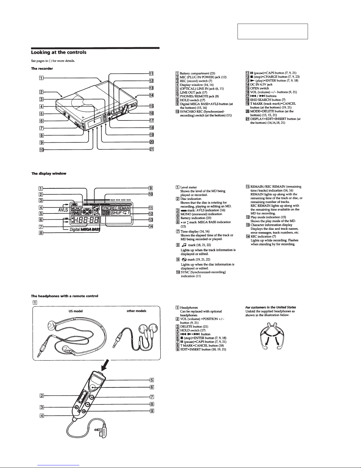
– 4 –
SECTION 1
GENERAL
This section is extracted from
instruction manual.
– 5 –
SECTION 2
SELF-DIAGNOSTIC
2-1. GENERAL
This set uses the self-diagnostic system in which if an error occurs
in playback/recording mode, the error is detected by the model
control and power control blocks of the microprocessor and information on the cause is stored as history in EEPROM.
By viewing this history in test mode, it helps you to analyze a fault
and determine its location.
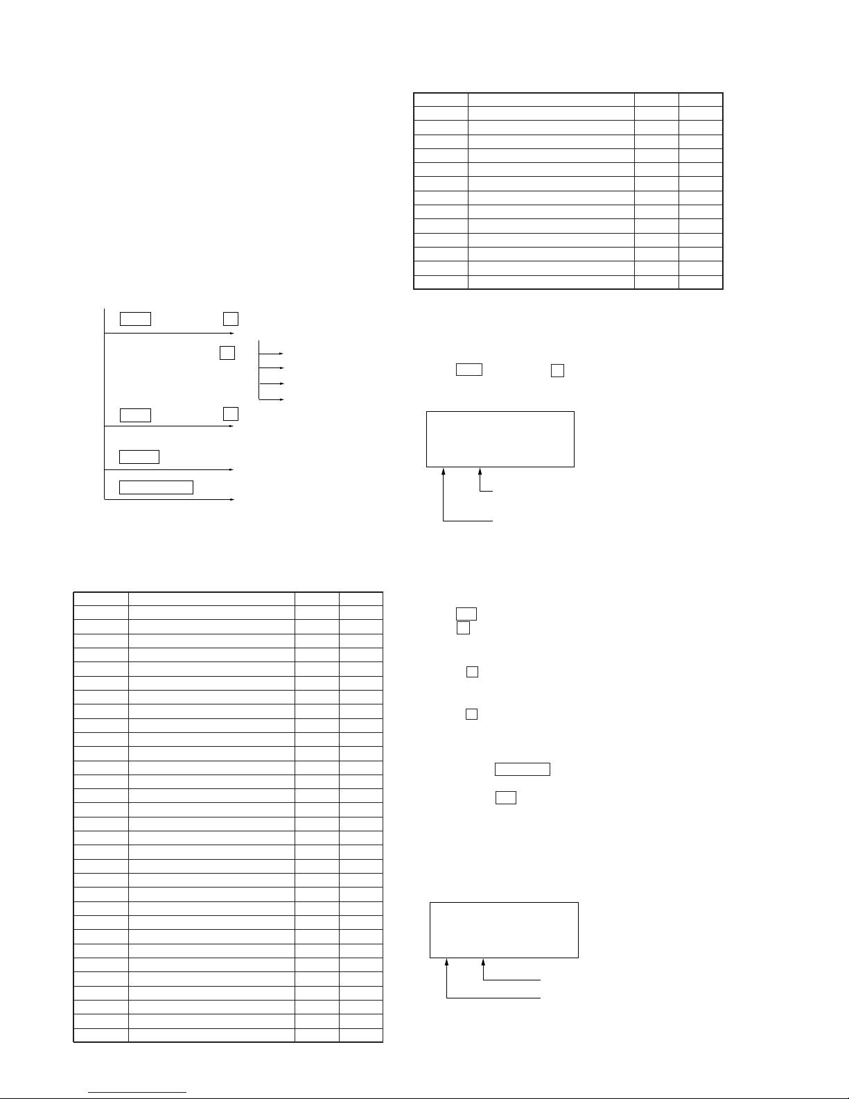
2-2. TEST MODE SETTING
There are two different methods to set the test mode:
1 Short BP801 (TEST) on the main board with a solder bridge
(connect pin @§ of IC801 to the ground). Then, turn on the
power.
2 In the normal mode, use the keys on the unit to perform the
following operations:
Press and hold down ( and press the keys below in this turn:
+ n + n =n = n + n = n + n
= n P n P
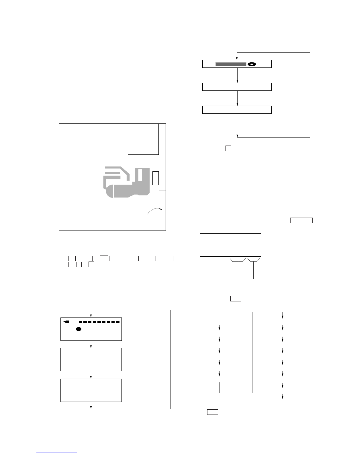
2-3. OPERATION IN TEST MODE SETTING
When the test mode is set, the LCD shows repeated cycles of the
following display:
1) Unit LCD
2) Remote controller LCD
• Holding down P allows the current display to be maintained
while it being depressed.
2-4. RELEASING THE TEST MODE
For test mode set with the method 1:
Turn off the power and open the solder bridge on BP801 on the
main board.
For test mode set with the method 2:
Turn off the power.
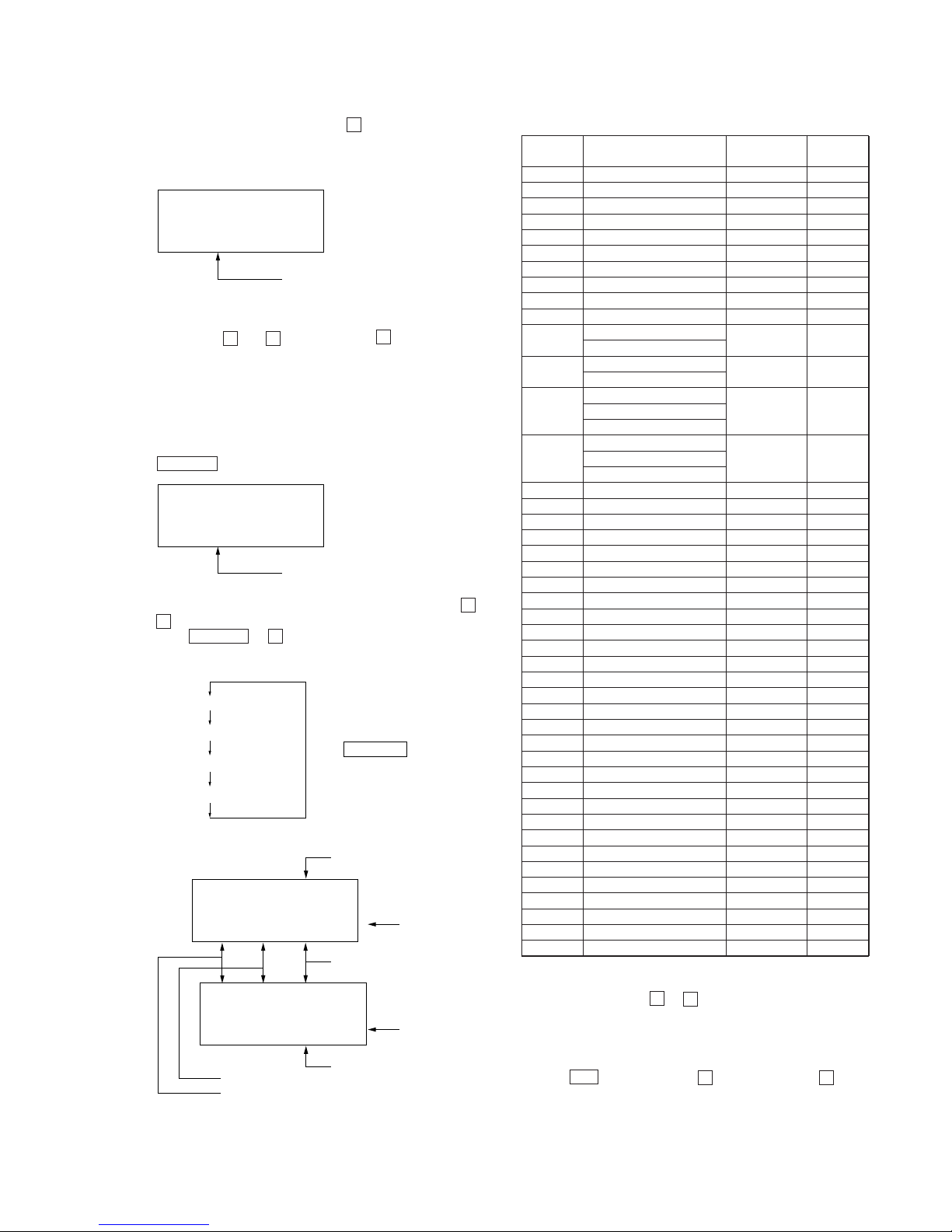
2-5. SELF-DIAGNOSTIC MODE
1. Go into the test mode.
2. With the unit LCD indicators all flashing, press DISPLAY key
to go into the self-diagnostic mode.
3. Then, eac h time ) ke y is pressed, the reference information
display changes as given below.
• Press = key to go back to the previous display.
C401
X801
26
25
IC801
IC301
BP801
(TEST)
MAIN BOARD (SIDE B)
All ON
All OFF
Microprocessor
version
display
Vr. 1.00
188:88 pppppp
ı
1st ‚ XX
1st 1 ‚‚
1st 2 ‚‚
1st ‚ XX
N ‚ XX
N 1 ‚‚
N 2 ‚‚
N-1 ‚ XX
N-1 1 ‚‚
N-1 2 ‚‚
N-2 ‚ XX
N-2 1 ‚‚
N-2 2 ‚‚
R XXXX
(return)
888
ı
Vr. 1.‚‚
All ON
All OFF
Microprocessor
version
display
Error indication code
History code
1st0 00
– 6 –
• Description of History Codes
History code number Description
1st 0 The first error
1st 1
1st 2
00 indicated
N 0 The last error
N1
N2
00 indicated
N-1 0 One error before the last.
N-1 1
N-1 2
00 indicated
N-2 0 Two errors before the last.
N-2 1
N-2 2
00 indicated
R Total recording time *1)
*1) Total recording time
Total recording time is recorded in minutes as an index for load to
the OP . It is recorded in he xadecimal format and up to 65,535 min.
(about 886 discs of 74-minute disc) can be counted. It returns to
“0000h” when recorder goes beyond this limit.
Example :REC 000A n Approx. 10 min.
REC 00A0 n Approx. 160 min.
REC 0A00 n Approx. 2,560 min.
• Description of Error Indication Codes
Problem Indication code Meaning of code Description
No error 00
Abnormal stop
during recording
Abnormal disc RPM.
01 Servo error Focus out of alignment.
Attempt to access an abnormal address.
02 ADIP read error Unable to read the ADIP address.
03 Shock detected during write Jumped by 1.5 tracks or more due to shock during write.
Shock detected during
04
laser down
Shock detected when laser was moving down.
Abnormal stop
during playback
11 No focus applied Focus could not be applied.
12 CRC error Unable to read the address.
15 FG error Abnormal rotation of disc.
Abnormal stop of
recording/playback
caused by power
system
21 Lower voltage due to overload Power voltage reduced due to overload.
22 Momentary interruption Momentary interruption detected.
23
Lower power voltage in motor Power voltage for motor continuously reduced to less than
system 1V.
24 Low power voltage in DSP
2-6. CLEARING THE ERROR INDICATION CODE
AND TOT AL RECORDING TIME
After repair, reset the error indication code.
Reset the total recording time when you have replaced the OP.
1. Go into the self-diagnostic mode. (See page 5.)
2. To reset the error indication code, slide REC c key when
the code is displayed.
(All data including 1st, N , N-1 and N-2 are reset.)
3. T o reset the total recording time, slide REC c key when the
time is displayed.
– 7 –
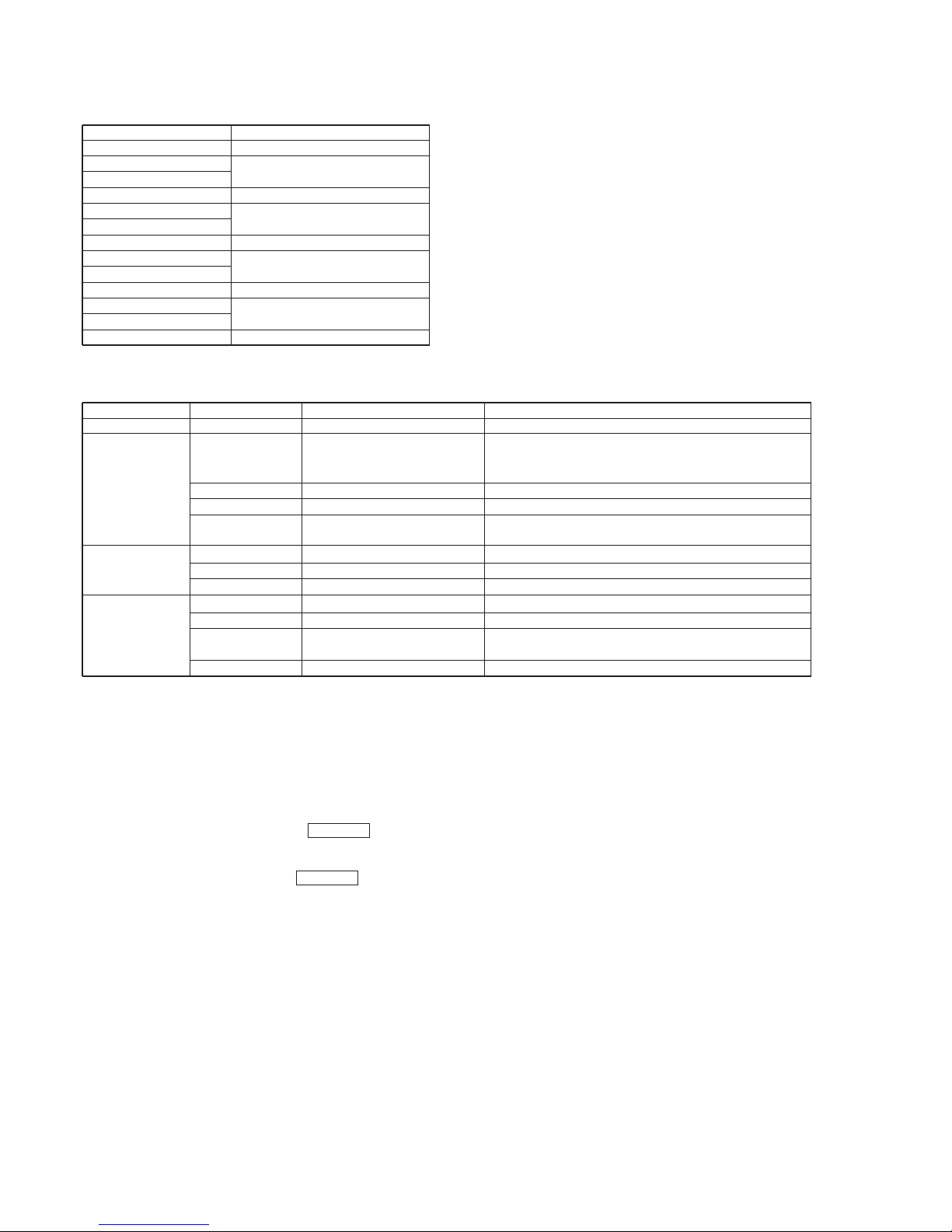
Note : This set can be disassemble according to the following sequence.
SECTION 3
DISASSEMBLY
3-1. PANEL, BOTTOM
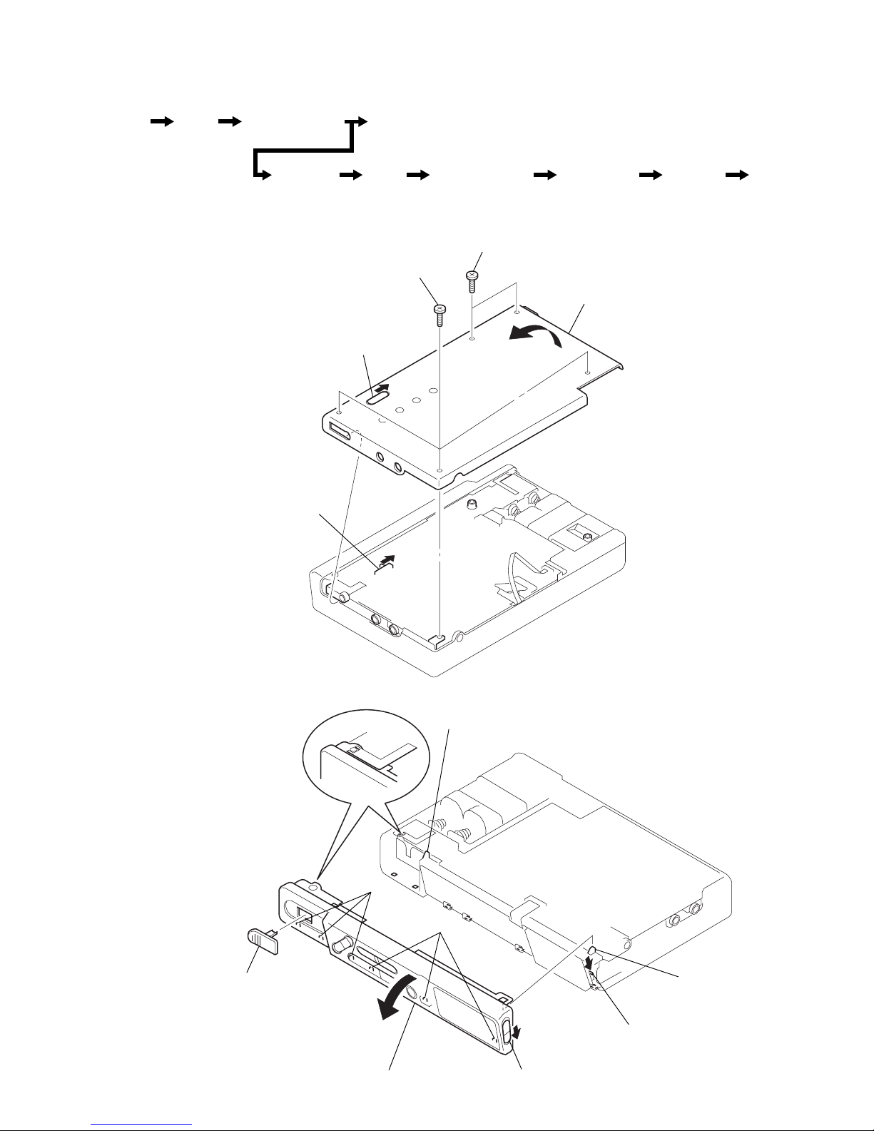
3-2. PANEL (SV) ASSY, FRONT
Note : Follow the disassembly procedure in the numerical order given.
Set Panel,
Bottom
Panel (SV) Assy,
Front
Panel (SV) Assy,
Upper
LCD Module
Connector Main
Board
Cabinet (SV)
Ass
y
OP Block
Ass
y
Holder
Ass
y
1
1.7x4.5, tapping
2
1.7x4.5, tapping
3
panel, bottom
knob
switch
1
knob (OPEN)
2
claw
5
panel (SV) assy, front
3
claw
4
claws
claws
knob
switch
– 8 –
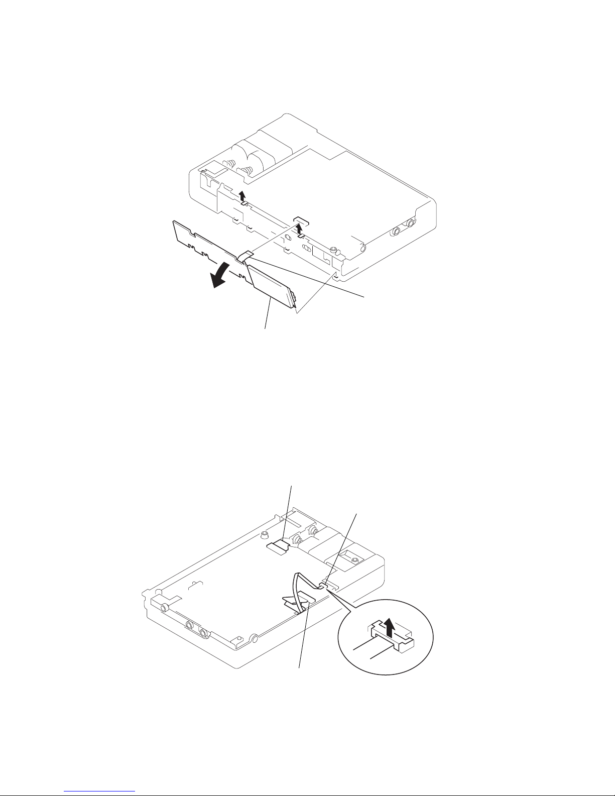
3-3. LCD MODULE
3-4. CONNECTOR
5
LCD module
1
CN801
2
4
3
1
CN601
2
CN702
3
CN701

– 9 –
3-5. MAIN BOARD
3-6. PANEL (SV) ASSY, UPPER
1
1.7x4.5, tapping
claws
2
1.7x4.5, tapping
3
4
MAIN board
4
claw
3
bearing (stopper
)
1
M1.4, precision
8
panel (SV) assy, upper
6
boss
5
claw
2
7

– 10 –
3-7. CABINET (SV) ASSY
3-8. OP BLOCK ASSY
1
MD, step
2
MD, step
4
cabinet (SV) ass
y
3
mechanism block assy
1
M1.4x3.0 locking
3
shaft, mai
n
4
flexible board
adhesive sheet
OP block assy
2
M1.4x3.0
– 11 –
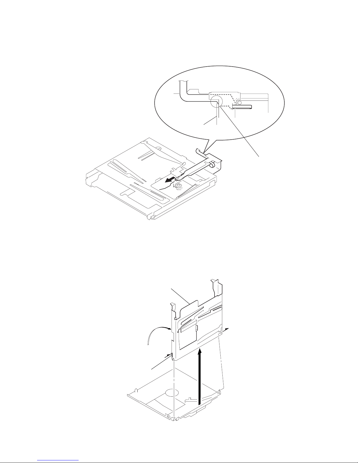
3-9. HOLDER ASSY
• Location of the Flexible Board
• Be careful to avoid contact
of the lens with the chassis
when installing the OP block
assy.
Align this portion of the
flexible board with the
marked line on the holder.
marked line
1
claw
4
holder assy
2
3
• Notes for Installation of the OP Block Assy
– 12 –
SECTION 4
TEST MODE
4-1. GENERAL
This set provides the Overall adjustment mode (Assy mode) that
allows CD and MO disk to be automatically adjusted when in the
test mode. In this Assy mode, the system discriminates between
CD and MO disk and then automatically perform adjustments for
them in sequence. If a fault is found, the system displays its location. Also, the Serv o mode allows each indi vidual adjustment to be
automatically adjusted.
4-2. TEST MODE SETTING
See page 5.
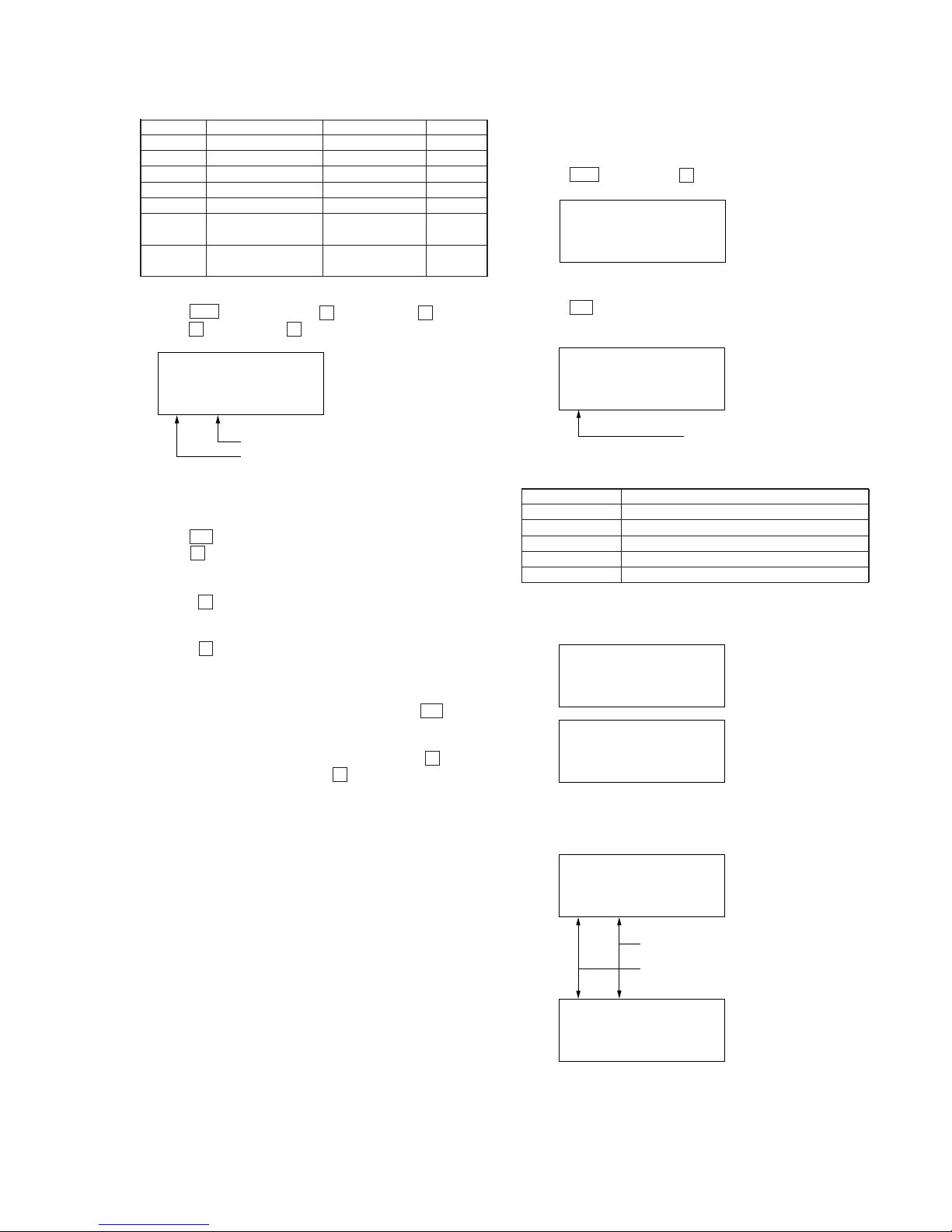
4-3. TEST MODE STRUCTURE
Test mode
4-4. MANUAL MODE
(1) Servo Mode
• How to Transfer in the Servo Mode:
Mode No. Test Description Check Write
000 Servo mode
010 Offset correction value indication
011 VC offset correction
012 Focus bias correction
013 FE offset correction
014 ABCD offset correction
015 All servo ON
016 Temperature indication
020 Laser power adjustment
021 Laser CD/MO read adjustment ® (08)
022 Laser MO write adjustment ® (4C)
023 Sled normal ® (45)
024 Sled intermittent ® (65)
025 Sled access ® (30)
030 MO test adjustment
031 MO focus search adjustment
032 MO read EF balance adjustment ® (0F)
033 MO read ABCD level ® (07)
034 MO write EF balance adjustment ® (10)
035 MO write ABCD level ® (18)
036 Laser MO read adjustment ® (08)
037 MO focus gain ® (30)
038 MO tracking gain ® (30)
039 MO focus bias ®® (0B)
040 Low reflection CD test adjustment
041
Low reflection CD focus search adjustment
042
Low reflection CD EF balance adjustment
® (10)
043 Low reflection CD ABCD level ® (06)
044 Laser low reflection CD read ® (08)
045 Low reflection CD focus gain ® (30)
046 Low reflection CD tracking gain ® (30)
Mode No. Test Description Check Write
047 Low reflection CD focus bias ®® (00)
050 CD test adjustment
051 CD focus search adjustment
052 CD EF balance adjustment ® (10)
053 CD ABCD level adjustment ® (15)
054 Laser CD read ® (08)
055 CD focus gain ® (30)
056 CD tracking gain ® (30)
057 CD focus bias ®® (00)
060 Recording test
061 32 cluster full recording
062 Recording shock
063 32 cluster full playback
Check : Mode to display error rate and cluster.
Write : Mode to permit adjustment (Default value given in paren
theses).
1. Go into the test mode.
2. Press + or VOLUME + key to set the servo mode.
Unit LCD display
3. Press the keys below to change the mode No.
( : Increases the one place.
p : Sets the one place to 0.
This key brings the ten place to 0 if the one place is
0.
VOLUME + :Increases the ten place by 10 if the one place is 0.
Increases the adjustment value if the one place
is non-zero.
VOLUME – : Decreases the ten place by 10 if the one place is 0.
Decreases the adjustment value if the one place is
non-zero.
Note) Press the REC c key is the mode “33” to shift to the
mode “34”.
Press the ( key is the mode “34” to shift to the mode
“35”.
• How to Adjust in Servo Mode:
1. When the servo mode is set to the appropriate mode for each
adjustment, the lower two digits of the mode No. and the value
stored in EEPROM are displayed and flashing.
Manual Mode
Servo Mode
Audio Mode
Mechanism Mode
Power Mode
or VOLUME key
VOLUME key
Overall Adjustment Mode
or VOLUME key
Hybrid Mode (ALL Mode)
+
–
+
=
+
EDIT/ENTER key
MODE key
Key Check Mode
(Assy Mode)
Adjustment value
(The data can be changed/written when flashing.
)
Mode No.
(The lower two digits are indicated.
Three digits are indicated on the
remote controller LCD.)
XX XX SERVO
Adjustment value (flashing
)
Mode No. (lower two digits
)
XX XX SERVO
– 13 –
(2) Audio Mode
• How to Transfer in the Audio Mode
Mode No. Test Description Write
Change
Description
100 Audio mode
110 Audio playback
111 L/R=1 kHz 0 dB Playback VOL HP output
112 L=1 kHz 0 dB Playback VOL HP output
113 R=1 kHz 0 dB Playback VOL HP output
114 L/R – ∞ dB Playback VOL HP output
115
L/R=1 kHz 0 dB & EVR max
Playback VOL HP output
116
L/R=1 kHz 0 dB & AVLS on
Playback VOL HP output
117 INFI ZERO & BEEP Playback VOL HP output
120 Audio recording test
121 LINE manual recording
Recording VOL HP output
*1) MIC manual recording
122
DEMP LINE manual recording
Recording VOL HP output
*1) DEMP MIC manual recording
123 LINE automatic recording
*1) OPT automatic recording HP VOL HP output
MIC automatic recording
124
DEMP LINE automatic recording
*1)
DEMP OPT automatic recording
HP VOL HP output
DEMP MIC automatic recording
130 DIGITAL A GC ADJ1
131 MIC UP SR ® (30)
132 MIC DOWN SR ® (FA)
133 MIC THD0 ® (D0)
134 MIC GAIN ® (00)
135 MIC A TT A CK ® (A0)
136 MIC RECOVER ® (F8)
137 MIC THD2 ® (F0)
138 MIC GAIN2 ® (D0)
139 MIC RTIME ® (01)
140 DIGITAL A GC ADJ2
141 LINE UP SR ® (17)
142 LINE DOWN SR ® (FF)
143 LINE THD0 ® (D0)
144 LINE GAIN ® (0C)
145 LINE A TT A CK ® (33)
146 LINE RECOVER ® (FB)
147 LINE THD2 ® (E4)
148 LINE GAIN2 ® (5F)
149 LINE RTIME ® (04)
150 DIGITAL A GC ADJ3
151 MAN UP SR ® (C0)
152 MAN DOWN SR ® (40)
153 AUTO THD3 ® (51)
154 AUTO LMT UP SR ® (FF)
155 AUTO LMT DOWN SR ® (E0)
156 MAN THD3 ® (51)
157 MANU LMT UP SR ® (FF)
158 MANU LMT DOWN SR ® (A0)
159 THD1 ® (1A)
*1) The port is detected and the input is automatically selected.
Contents changed : Contents to be changed when VOLUME
+ or – key is pressed.
Write : Mode to permit adjustment
(Default value given in parentheses)
1. Go into the test mode.
2. Press + key or VOLUME + key and VOLUME + key in
this turn to set the audio mode.
2. To perform automatic adjustment for an adjustment item with
the mode number 030 to 047, press P key.
If the result of adjustment is OK, the adjustment value changes
from flashing to steady on and it is automatically written to
EEPROM.
3. To perform manual adjustment, change the adjustment v alue with
VOLUME + or – key, and press P key to write it to
EEPROM.
Note) Normally, automatic adjustment should be performed. Do
not execute manual adjustment.
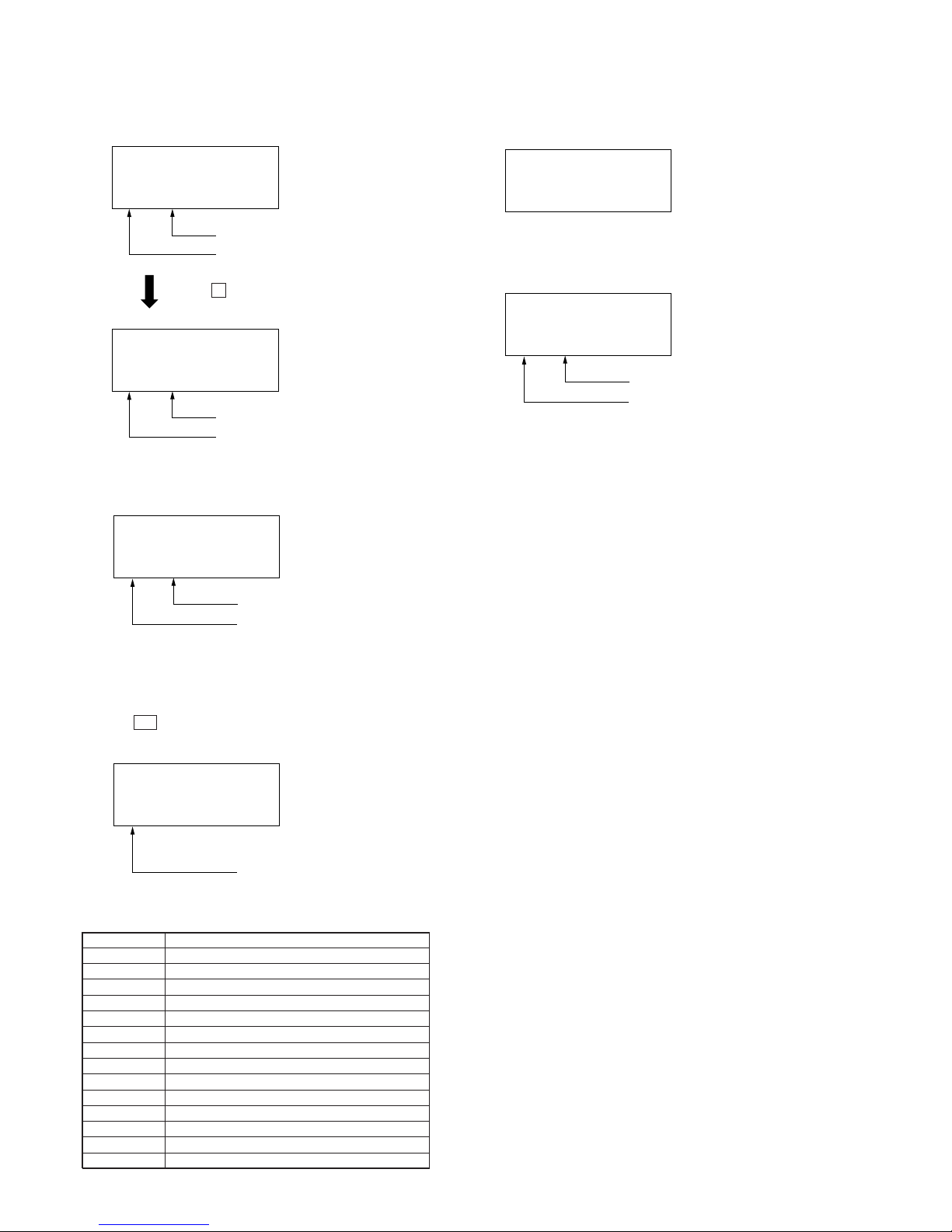
• System Gain Mode
1. This mode allows the system gain to be freely adjusted. Press
DISPLAY key to enter this mode.
2. Increase or decrease the adjustment value with V OLUME + or
– key.
3. Press DISPLAY or p key to return to the normal mode.
4. For the error rate display enabled:
Note) In normal service, do not adjust the system gain mode.
Adjustment value
(flashing to steady on
)
32 OF SERVO
Adjustment value (flashing
)
32 OF S-GAIN
Adjustment value (flashing)
Mode No. (lower two digits)
39 OA 000a4F
39 OA 000b4F
Cluster value
Indicate of block error rate
ATT error value
Block error value
Indicate of AT error rate
Normal Mode
System gain Mode
AT error rate
Press DISPLAY key
Block error rate

– 14 –
3. Press the keys below to change the mode number.
( : Increases the one place.
p : Sets the one place to 0.
This key brings the ten place to 0 if the one place
is 0.
VOLUME + : Increases the ten place by 10 if the one place is 0.
Increases the adjustment value if the one place is
non-zero.
VOLUME – : Decreases the ten place by 10 if the one place is 0.
Decreases the adjustment value if the one place is
non-zero.
• How to Adjust in the Audio Mode
1. When the audio mode is set to the appropriate mode for each
adjustment, the lower tow digits of the mode No. and the value
stored in EEPROM are displayed and flashing.
2. Change the adjustment value with VOLUME + or – key and
press P key to write the new value to EEPROM.
• How to Check in the Audio Mode
The audio mode allows the checks below to be performed:
1. For the mode numbers of 111 to 113, 115 and 116, pressing P
key will activ ate a beep. But for the mode number of 117, pressing P key will not activate a beep. (No beep sounds when
c HOLD switch is put on.)
2. For the mode numbers of 121 to 124, pressing Digital MEGA
BASS key will display the DBB mode for the adjustment v alue.
1 : Mode 1
2 : Mode 2
13 : OFF
(This will not be accepted when the LINE OUT jack is plugged.
The display will be 13 : OFF when LINE OUT jack is plugged
in Modes 1 and 2.)
Unit LCD display (3) Mechanism Mode
• How to Transfer the Mode in the Mechanism Mode:
Mode No. Test Description Operation
200 FUNCTION Stepper control
210 MECHA test Initial position return
211 HEAD adjustment Operation variation changing (19)
212 REC position Recording head descent
220 RESUME Resume
221 RESUME CLEAR Resume clear/initialization
( ) : Default value
1. Go into the test mode.
2. Press + or V OLUME + and VOLUME + and VOLUME
+ in this turn to set the mechanism mode.
Unit LCD display
3. Press the keys below to change the mode No.
( : Increases the one place.
p : Sets the one place to 0.
This key brings the ten place to 0 if the one place is
0.
VOLUME + : Increases the ten place by 10 if the one place is 0.
Increases the adjustment value if the one place
is non-zero.
VOLUME – : Decreases the ten place by 10 if the one place is 0.
Decreases the adjustment value if the one place is
non-zero.
• How to Check in the Mechanism Mode
The mechanism mode allows the checks below to be performed:
1. For the mode numbers of 200, 210 to 212, 220 and 221, pressing
= key will move the optical pickup to the inner radius.
Pressing + key will move the pickup to the outer radius.
2. For the mode numbers of 211 and 212, pressing P key will
start aging. Pressing p key will stop aging.
• Mode No. 211 ... Sled aging with stepper at playback position.
• Mode No. 212 ... Sled aging with stepper at recording position.
3. With the mode number 210 selected, pressing P k ey will start
aging with steeper at between home and recording positions.
p key will stop aging.
Adjustment value
(The data can be changed/written when flashing.
)
Mode No.
(Lower two digits are displayed.)
XX XX AUDIO
Adjustment value
Mode No.
(Lower two digits are displayed.
)
XX XX MECHA
– 15 –
1. Go into the test mode.
2. Press + key or VOLUME + and VOLUME + and VOLUME + and VOLUME + in this turn to set the power mode.
3. Press the keys below to change the mode No.
( :Increases the one place.
p : Sets the one place to 0.
This key brings the ten place to 0 if the one place is
0.
VOLUME + : Increases the ten place by 10 if the one place is 0.
Increases the adjustment value if the one place
is non-zero.
VOLUME – : Decreases the ten place by 10 if the one place is 0.
Decreases the adjustment value if the one place is
non-zero.
Note) With the mode number 310 selected, pressing ( key will
transfer to the mode number (311) for the currently operating power.
With the mode number 300 selected, pressing P key will
set the sleep mode. Pressing p key will release it.
• How to Check in the Power Mode
1. For the mode numbers of 311, the voltage of the currently
operating power is displayed.
4-5. O VERALL ADJUSTMENT MODE (ASSY MODE)
• How to Adjust in Assy Mode
1. Go into the test mode.
2. Press = or VOLUME – key.
3. Insert the test CD (TDYS-1) or an available SONY CD.
4. Press ( key . The system discr iminates between CD and MO
and performs automatic adjustment for CD.
• CD Automatic Adjustment
Mode No. Adjustment Description
052 CD EF balance adjustment
053 CD ABCD level adjustment
055 CD focus gain
056 CD tracking gain
057 CD focus bias
5. If the result of automatic adjustment is OK, the following display appears:
6. If the result of automatic adjustment is NG, the following display appears:
Adjustment value
Mode No.
(Lower two digits are displayed.
)
XX XX POWER
XX ASSY-M
Mode No. under adjustment.
51 CD-RUN
CD-OK
MD-OK
(CD)
(MD)
XX XX MD-OK
Result of adjustment
NG mode No. (lower two digits
)
XX XX CD-NG
(4) Power Mode
Mode No. Test Description Indication value Remark
300 POWER test
310 POWER SUPPLY
311 DC IN +B voltage value
320 CHG TEST
321 Charging start
322 BATT under CHGMNT
voltage value
323 BATT under +B CHGMNT
voltage value
– 16 –
* For the mode numbers of 039 and 057, if the focus bias value is
NG, the following display is repeated:
While P key is being depressed
* For the mode numbers of 039 and 061, if the At error rate is NG,
the following display is repeated:
7. If NG, set the servo mode. Perform automatic adjustment for
the items not accepted (see the servo mode).
8. Insert a MO disk.
9. Press ( key . The system discriminates between CD and MO
and performs automatic adjustment for the MO disk.
• MO Automatic Adjustment
Mode No. Adjustment Description
032 MO read EF balance adjustment
033 MO read ABCD level
034 MO write EF balance adjustment
035 MO write ABCD level
037 MO focus gain
038 MO tracking gain
061 32 cluster full recording
062 Recording shock
063 32 cluster full playback
039 MO focus bias
042 Low refrection CD EF balance adjustment
043 Low refrection CD ABCD level
044 Laser low reflection CD read
046 Low refrection CD tracking gain
10. If the result of automatic adjustment is OK, the following display appears:
11. If the result of automatic adjustment is NG, the following display appears:
12. If NG, set the servo mode. Perform automatic adjustment for
the items not accepted (see the servo mode).
4-6. HYBRID MODE, KEY CHECK MODE
These modes are not used in normal service.
Focus bias value
Mode No.
Error code (01 to 04)
Meaning of focus bias
55 30
77 01
At error value
Mode No. (lower two digits
)
39 03
Mode No. (lower two digits)
61
00
Result of adjustment
NG Mode No. (lower two digits
)
82 00
– 17 –
SECTION 5
ELECTRICAL ADJUSTMENTS
PRECAUTIONS FOR ADJUSTMENT
1) Perform all adjustments in the order given in the test mode.
After adjusting, exit the test mode.
2) Use the following tools and measuring instruments.
• Test CD TDYS-1
(Part No. : 4-963-646-01)
• Recorded MO disk PTDM-1
(Part No. : J-2501-054-A)
• Laser power meter LPM-8001
(Part No. : J-2501-046-A)
• Oscilloscope (Frequency band above 40 MHz. Perform the
calibration of probe first before measuring.)
• Digital voltmeter
3) Unless specified othewise, supply DC 4.5V from the DC IN 4.5V
jack.
4) Swtich, knob positions
HOLD switch .............. OFF
AVLS switch ................ NORM
LASER POWER CHECK
Connection :
Adjustment Method :
1. Set the servo mode of the test mode (Mode : 000).
2. Press the ( key, and set the laser power adjustment mode
(Mode : 020) using the VOLUME + or – key.
3. Press the = key and move the optical pick-up to the inner
most circumference.
4. Open the cover and set the laser power meter on the objective
lens of the optical pick-up.
5. Press the ( key, and set the laser CD/MO read adjustment
mode (Mode : 021).
6. Check that the laser power meter reading is 0.85 ± 0.085 mW.
7. Check that the voltage between AP5117 (VCC) and AP574
(LDI0) at this time is below 40 mV.
8. Press the ( key, and set the laser MO write adjustment
mode (Mode : 022).
9. Check that the laser power meter reading is 6.8 ± 0.68 mW.
10. Press the P key to finalize the adjustment data.
11. Check that the voltage between AP5117 (VCC) and AP574
(LDI0) at this time is below 80 mV.
12. Press the p key.
13. Exit the test mode.
Adjustment Location : See page 19.
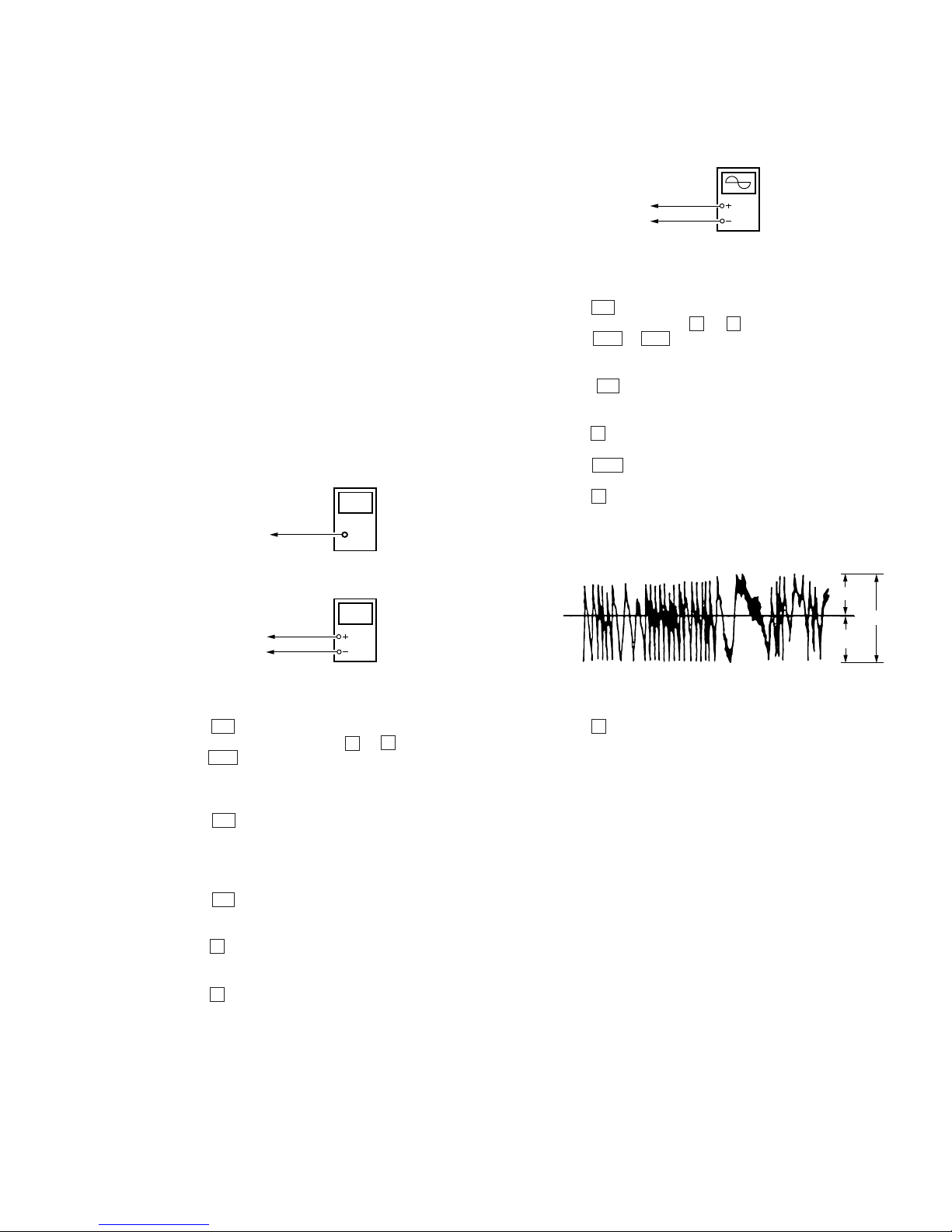
MO TRA VERSE ADJUSTMENT
Connection :
Adjustment Method :
1. Set the servo mode of the test mode (Mode : 000).
2. Press the ( key , and set the MO test adjustment mode (Mode
: 030) using the VOLUME + or – key.
3. Press the = or + key and move the optical pick-up to
the center circumference.
4. Insert any MO disk available on the market.
5. When the ( key is pressed, the MO read EF balance adjustment mode (Mode : 032) will be set after MO focus search
adjustment mode (Mode : 031).
6. Press the P key to perform automatic adjustment, and check
that the traverse waveform is symmetrical at the top and bottom.
7. Slide the REC key and set the MO write EF balance adjust
ment mode (Mode : 034).
8. Press the P key to perform automatic adjustment, and check
that the traverse wav eform is symmetrical at the top and bottom.
9. Check that the traverse level at this time is above 1.0 Vp-p.
10. Press the p key.
11. Exit the test mode.
Note) Using a recorded disk in this adjustment will erase the data.
Adjustment Location : See page 19.
digital voltmete
r
MAIN board
AP5117 (VCC)
AP574 (LDI0)
laser
power meter
Optical pick-up
objective lens
oscilloscop
e
MAIN board
SP526 (TE)
AP503 (VC)
A
B
C
Specification : A = B, C 1.0 Vp-p
0 V
(Traverse waveform)
>
=
 Loading...