

Page 1
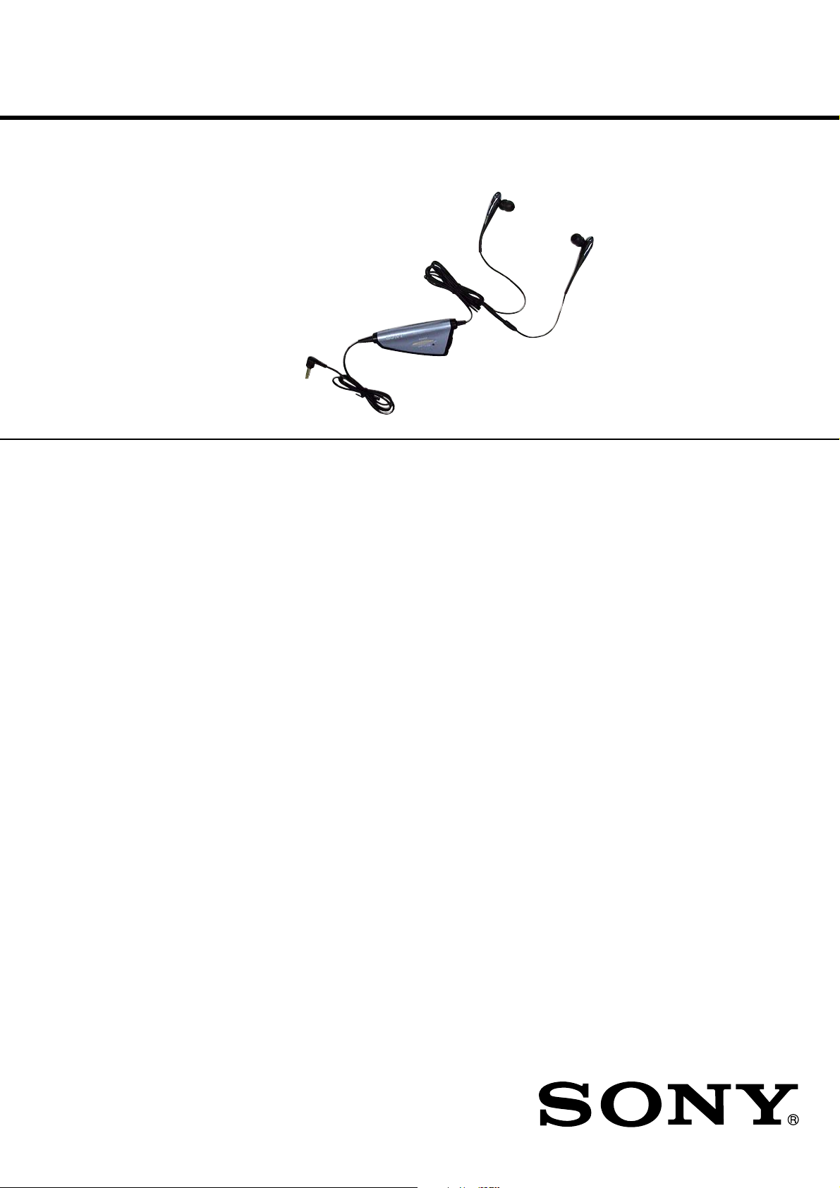
MDR-NC11A
SERVICE MANUAL
Ver. 1.1 2005.08
SPECIFICATIONS
General
Type dynamic, closed
Driver units 9 mm dia
Power handling capacity
50 mW
Impedance 20 ohms at 1 kHz
(when the power is on)
8 ohms at 1 kHz
(when the power is off)
Sensitivity 102 dB/mW (when the power is on)
98 dB/mW (when the power is off)
Frequency response
10 − 22,000 Hz
Frequency range of active noise attenuation
50 − 1,500 Hz more than 10 dB at
300 Hz
Power source DC 1.5 V, 1 × R03 (size AAA) battery
Mass Approx. 47 g (1.7 oz) including batterybox, cord, and battery
US Model
Tourist Model
Note on chip component replacement
• Never reuse a disconnected chip componet
• Notice that the minus side of a teamtalum capacitor may be damaged by
heat
Supplied accessories
Sony R03 (size AAA) battery (1)
Earbuds (S × 2, M × 2, L × 2)
Holder (1)
Carrying case (1)
Plug adaptor for in-flight use* (single/dual) (1)
Operating Instructions (1)
* May not be compatible with some in-flight music services.
Design and specifications are subject to change without notice.
9-879-188-02
2005H05-1
© 2005.08
Sony Corporation
Personal Audio Group
Published by Sony Engineering Corporation
NOISE CANCELING HEADPHONES
Page 2
MDR-NC11A
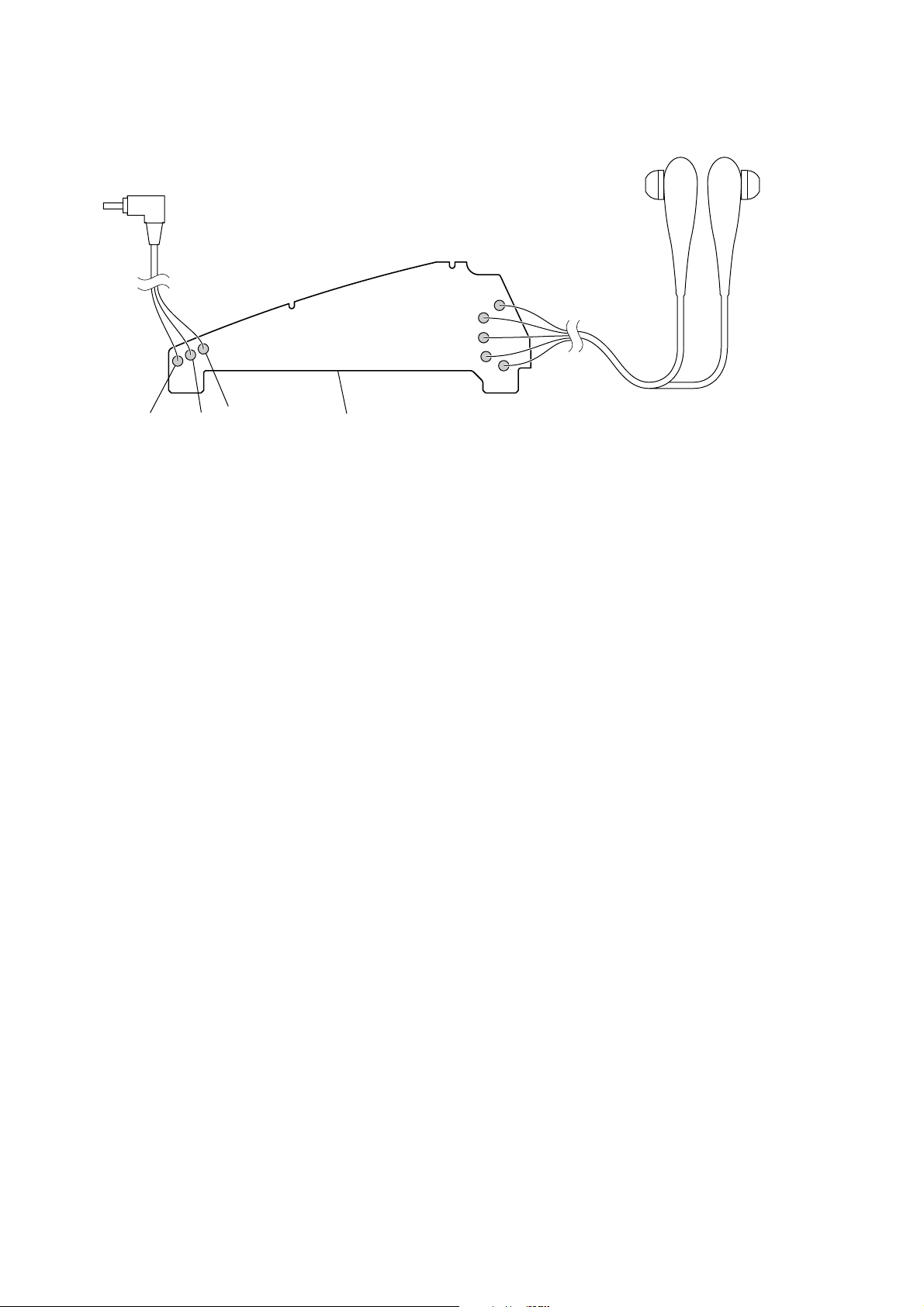
WIRING DIAGRAM
SECTION 1
SERVICING NOTE
brown
blue
yellow
green
red
red
white
black
main board (conductor side)
2
Page 3
This section is extracted from
instruction manual.
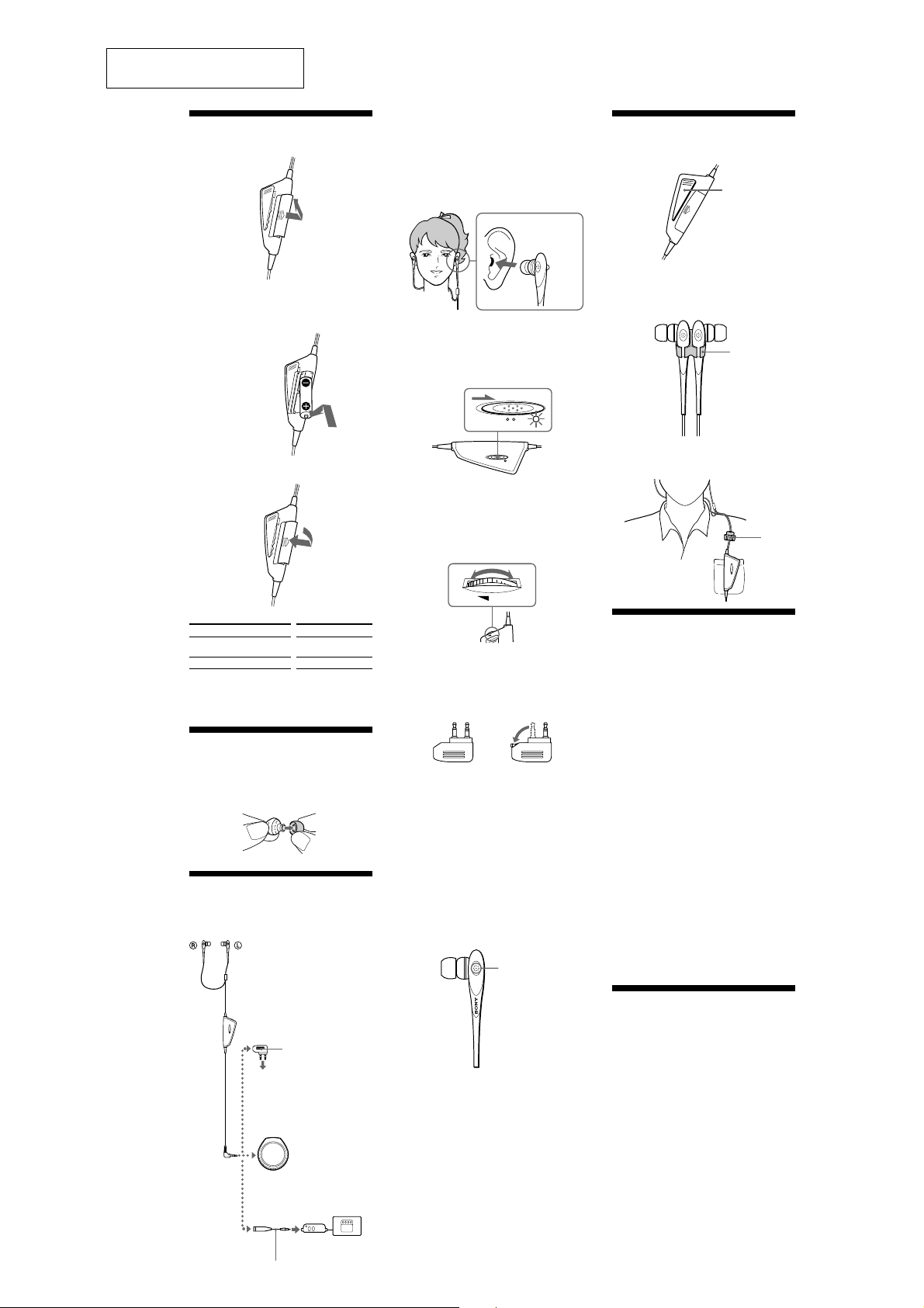
Installing a battery
Open the lid on the rear side of the battery box.
1
SECTION 2
GENERAL
2
Wear the headphones marked R in your right
ear and the one marked L in your left ear. Push
the earbud into your ear carefully so that the
earbud fits the hole of your ear snugly.
Note
Unless the headphones correctly fit your ears, noise
canceling will not function.
Adjust the earbuds position to sit on your ear comfortably,
and push them into the inside of your ears so that they fit
your ears snugly.
MDR-NC11A
Using the clip
You can fasten the battery box by its clip on a shirt pocket.
Clip
2
Insert one R03 (size AAA) battery by matching
the + and − on the battery to the + and − in the
battery box.
Insert the # end first.
3
Close the lid.
Battery life
Battery
Sony alkaline battery LR03/AM4 (N)
Sony battery R03/UM-4 (NU)
When to replace the battery
Replace the battery with a new one when the POWER
indicator dims.
Approx. hours
40 hours
20 hours
Selecting the
earbuds
The M size earbuds are attached to the headphones before
shipment. If you feel the M size earbuds do not suit your
ears, replace them with the supplied S or L size earbuds.
Listening to music
Connect the headphones to the AV equipment.
1
When connecting to dual or
stereo mini jacks of in-flight
musicservices.
Plug adaptor (supplied)
To headphone jack
on airplane seats
When connecting to the
headphone jack (stereo mini
jack) of a WALKMAN*, etc.
When connecting to the
remote control of a
WALKMAN*, etc.
R
3
Turn on the power of the headphones.
The power indicator lights in red. The power
switch is located on the battery box. When
power is turned on, ambient noise is reduced,
and you can listen to music more clearly at a
lower volume.
4
Turn on the power of the AV equipment.
5
Adjust the volume.
Turn the VOL control.
(If you turn down the volume, the sound does
not mute completely.)
*WALKMAN is a registered trademark of Sony
Corporation.
Notes on using on the airplane
•
The supplied plug adaptor can be connected to dual and
stereo mini jacks.
•
Do not use the headphones when use of electronic
equipment is prohibited or when use of personal
headphones for inflight music services is prohibited.
If you have any questions or problems concerning the
system that are not covered in this manual, please consult
the nearest Sony dealer.
After listening to music
Turn off the power of the headphones.
Notes
• The noise canceling function is only effective for noise in the
low frequency band. Although noise is reduced, it is not
canceled completely.
• Do not cover the microphone of the headphones with your
hands. The noise canceling function may not work properly.
• The noise canceling function may not work properly unless
the headphones are put on firmly.
• You can use the headphones even without turning on the
power. In this case, the noise canceling function is not active,
and the headphones operate as passive headphones.
• After you turn on the power of the headphones, you may hear
a slight hiss. This is the operating sound of the noise canceling
function, not a malfunction.
• In a quiet place, or depending on certain noises, you may feel
that the noise canceling function is not effective, or that noise
is accentuated. In this case, turn off the power of the
headphone.
• Interference noise can occur from nearby cellular phones.
Should this occur, locate the headphones further away from
the cellular phone(s).
dual jacks
L
L
POWER
ONOFF
VOL
L
O
V
stereo mini jacks
Microphone
When carrying the headphones
You can attach the headphones to the supplied holder to
keep them together. The headphones and the battery box
can also be separately stored in the partitioned carrying case
(supplied).
Holder
While using the headphones, you can attach the holder to
the headphone cord.
Holder
Precautions
•
Clean the headphones with a soft dry cloth.
•
Do not leave the jackplug dirty otherwise the sound may
be distorted.
•
Be sure to bring the headphones to the Sony dealer when
requiring a change of earbuds or repair work.
•
The CE mark on the unit is valid only for products
marketed in the European Union.
•
Do not leave the headphones in a location subject to direct
sunlight, heat or moisture.
•
Do not subject the headphones to excessive shock.
•
Handle the driver units carefully.
•
To clean the earbuds, first remove them from the
headphones, and then clean them with water and mild
detergent. After cleaning, dry each earbud carefully
before use.
•
The earbuds will need to be replaced from time to time. If
they are worn out by daily use or longtime storage,
replace them with new ones.
•
If you fell drowsy or sick while using these headphones,
stop use immediately.
Notes on headphones
Preventing hearing damage
Avoid using headphones at high volume. Hearing experts
advise against continuous, loud and extended play. If you
experience a ringing in your ears, reduce the volume or
discontinue use.
Do not use headphones while driving and
cycling, etc.
As headphones reduce outside sounds, they may cause a
traffic accident. Also, avoid listening with your headphones
in situations where hearing must not be impaired, for
example, a railroad crossing, a construction site, etc.
Features
•
Noise canceling headphones reduce ambient noise, and
provide a quieter environment to enhance audio
entertainment. Ambient sound is synthesized with an
anti-sound signal produced by the noise canceling circuit,
and reduced.
•
Ultra compact earphones with 9mm driver unit fits
comfortably in the ear and closed type earphone structure
delivers deep bass sound.
•
Soft silicon rubber earbuds are used for stable and
comfortable fit in the ears.
•
Volume control function for easy connecting to your
portable audio player.
•
New earphone holder minimizes cord tangles during
strage.
•
Operates as passive headphones when noise canceling
circuit is not activated.
•
Plug adaptor is supplied to connect directly to stereo or
dual jack of inflight music services.
PC-MP1HG
(not supplied)
3
Page 4
MDR-NC11A
SECTION 3
ELECTRICAL ADJUSTMENT
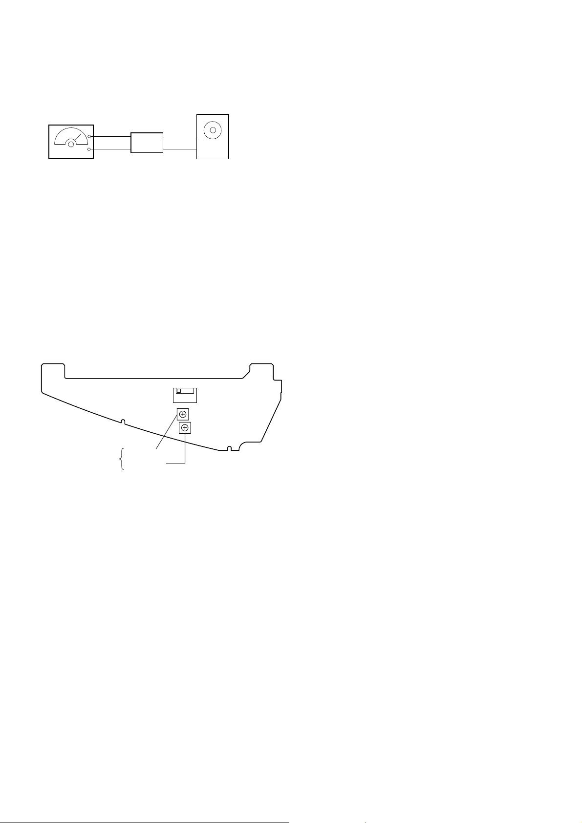
NOISE CANCEL VOLUME ADJUSTMENT
Connection:
speaker
AF oscillator
+
amplifier
–
Procedure:
1. Generate a sine wave of specific frequency (250 Hz) from a
AF oscillator, and output it from a speaker placed at the forward
position.
2. Mount this headphones on the ear, and turn on the [POWER]
switch.
3. With this headphones mounted, adjust the RV1 (L-ch) and
RV51 (R-ch) so that the volume from the speaker becomes
lowest aurally.
Note:
When the headphones are not covered with the ear pieces completely, the
adjustment may not be performed correctly.
Make sure that the ear pieces cover the headphone completely.
Adjustment Location:
– MAIN BOARD (Component Side) –
NOISE CANCEL RV51 (R-ch)
VOLUME ADJUSTMENT RV1 (L-ch)
S101
[POWER]
OFF t ON
4
Page 5

SECTION 4
DIAGRAMS
• Note for Printed Wiring Board and Schematic Diagram
MDR-NC11A
Note on Printed Wiring Board:
• X : parts extracted from the component side.
• Y : parts extracted from the conductor side.
•
(The other layers' patterns are not indicated.)
Caution:
Pattern face side: Parts on the pattern face side seen from
(Conductor Side) the pattern face are indicated.
Parts face side: Parts on the parts face side seen from
(Component Side) the parts face are indicated.
: Pattern from the side which enables seeing.
Note on Schematic Diagram:
• All capacitors are in µF unless otherwise noted. (p: pF)
50 WV or less are not indicated except for electrolytics
and tantalums.
• All resistors are in Ω and 1/
specified.
• C : panel designation.
• A : B+ Line.
• H : adjustment for repair.
• Power voltage is dc 1.5 V and fed with regulated dc po wer
supply from battery terminal.
• Voltages and waveforms are dc with respect to ground
under no-signal conditions.
no mark : POWER ON
(): POWER OFF
• Voltages are taken with a V OM (Input impedance 10 MΩ).
Voltage variations may be noted due to normal production tolerances.
• Waveforms are taken with a oscilloscope.
Voltage variations may be noted due to normal production tolerances.
• Circled numbers refer to waveforms.
• Signal path.
F : LINE INPUT (POWER ON)
J : LINE INPUT (POWER OFF)
4
W or less unless otherwise
5
Page 6

MDR-NC11A
• Waveforms
IC102 1 (S.D),
1
Q101 (Collector)
36.4 µs
5 mV/DIV, 20 µs/DIV
Q201-1 (Base)
2
200 mV/DIV, 20 µs/DIV
Q201-1 (Collector),
3
Q202-1 (Base)
36.4 µs
36.4 µs
20 mVp-p
1.1 Vp-p
0.8 Vp-p
Q202-2 (Collector)
7
5 mV/DIV, 20 µs/DIV
20 mVp-p
36.4 µs
200mV/DIV, 20 µs/DIV
Q201-2 (Base)
4
200mV/DIV, 20 µs/DIV
Q201-2 (Collector),
5
Q202-1 (Collector),
Q202-2 (Base)
36.4 µs
200 mV/DIV, 20 µs/DIV
Q202 (Emitter)
6
0.8 Vp-p
36.4 µs
1.3 Vp-p
70 mVp-p
36.4 µs
20 mV/DIV, 20 µs/DIV
6
Page 7

4-1. PRINTED WIRING BOARD
1 2 3 4 5 6
MAIN BOARD (COMPONENT SIDE)
A
IC101
DRY BATTERY
SIZE "AAA"
(IEC DESIGNATION R03)
1PC. 1.5V
S101
POWER
OFF ON
−
1
−
2
MDR-NC11A
• Semiconductor
Location
Ref. No. Location
D201 B-5
IC101 B-3
IC102 B-3
Q2 D-4
Q52 D-4
Q101 D-4
Q201 B-5
Q202 B-4
B
C
D
E
MAIN BOARD (CONDUCTOR SIDE)
P1
(LINE INPUT)
BLK
WHT
RED
JC101
IC102
D201
−
1
−
2
POWER ON
RV101
VOL
1-683-881-
BLU
YEL
GRN
BRN
RED
1-683-881-
12
(12)
GRN/BRN
RED/BRN
(MICROPHONE/HEADPHONE)
HP1
BRN
12
(12)
(L-ch)
(R-ch)
(L-ch)
(R-ch)
1
3
5
4
1B
2C
2B
2C
E
1C 1C
2B
E
1B
MDR-NC11A
77
Page 8

MDR-NC11A
Ver. 1.1
4-2. SCHEMATIC DIAGRAM BOARD
HP1
(1/2)
(MICROPHONE)
BLU
(L-ch)
1000p
P1
(LINE INPUT)
NAT
WHT
RED
BLK
• See page 6 for Waveforms
R1
2.7k
C2
0.047
R2 R4
4.7k 1k
C5
1
S101
POWER
C8
100
VOL
-1
-2
6.3V
6.3V
C58
100
-1 -2
VCC
GND
Q202
UMA4N-TR
LED DRIVE,
OSC
R206
820
C204
D201
CL-196HR
POWER ON
0.1
DRY BATTERY
SIZE"AAA"
(IEC DESIGNATION R03)
1PC. 1.5V
GRN
G/N
RED
R/N
HP1(2/2)
(HEADPHONE)
(L-ch)
(R-ch)
TP103
C111
10
C105
0.1
C112
10V
0.1
C201
1
R201
R101
47k
C104
0.01
C106
10V
27
10
R202
10k
C202
2200p
Q201
UMW1N-TR
LED DRIVE,
OSC
R13
R63
4.7
4.7
C15C65
0.10.1
R204R203
10k10k
C203
2200p
-1 -2
8.22.2
R64 R65 C67
2.2 8.2 220
C66C109
10
10V
C16
10
10V
R205
4.7k
C17R15R14
220
4V
4V
R6
47k
C6
1
RV1R5R3C113C1
2.2k470k4.7k0.010.1
ON
OFF
-1-2
C9 C12
0.22 2200p
C10R8 R11 C11
0.2218 10k 0.47
C59 C62
0.22 2200p
2SC4154TP
BUFFER AMP
R10R9
2.2k6.8k
Q2
R7 C7
2.2k 1
C13
R12
10k
0.22
TP3
TP53
C61R61C60R58
0.4710k0.2218
C63R62R60R59
0.2210k2.2k6.8k
DTA123YUA
SWITCHING
C14
2200p
C64
2200p
C108
0.01
10
10V
Q101
C114
0.01
TK70203CS2G0L
IC101RV101
LA4537M500/500
POWER AMP
REGULATOR
IC102
VIN VOUT
D
N
.D
S
G
JC101
D
N
G
0
(R-ch)
MDR-NC11A
1000p
R51 R56
2.7k 47k
YEL
NAT
C52
0.047
R52 R54
4.7k 1k
C55C51
10.1
Q52
2SC4154TP
C56
1
BUFFER AMP
R57 C57
RV51R53 R55
2.2k4.7k 470k
2.2k 1
88
Page 9

SECTION 5
EXPLODED VIEWS
MDR-NC11A
Ver. 1.1
NOTE:
• -XX and -X mean standardized parts, so they
may have some difference from the original
one.
• Color Indication of Appearance Parts
Example:
KNOB, BALANCE (WHITE) . . . (RED)
↑↑
Parts Color Cabinet's Color
• Items marked “*” are not stocked since they
are seldom required for routine service. Some
delay should be anticipated when ordering
these items.
• The mechanical parts with no reference
number in the exploded views are not supplied.
• Accessories are given in the last of the
electrical parts list.
HP1
7
7
not supplied
6
P1
4
13
2
not
supplied
1
Ref. No. Part No. Description Remark
13-235-824-01 KNOB, POWER (BLACK, BLUE)
13-235-824-11 KNOB, POWER (WHITE)
2 X-2024-592-1 CASE (UPPER) SUB ASSY (BLACK)
2 X-2024-594-1 CASE (UPPER) SUB ASSY (WHITE)
2 X-2024-977-1 CASE (UPPER) SUB ASSY (BLUE)
14
9
10
3
12
11
Ref. No. Part No. Description Remark
9 3-235-820-01 LID, BATTERY CASE (BLACK, BLUE)
9 3-235-820-11 LID, BATTERY CASE (WHITE)
10 X-2024-596-2 CASE (LOWER) SUB ASSY (WHITE)
10 X-3382-038-2 CASE (LOWER) SUB ASSY (BLACK, BLUE)
* 11 A-3178-431-A MAIN BOARD, COMPLETE
14
33-831-441-11 CUSHION (T)
43-236-543-01 BUSHING (LOWER), BATTERY CASE
(BLACK, BLUE)
43-236-543-21 BUSHING (LOWER), BATTERY CASE (WHITE)
63-235-828-01 BUSHING (UPPER), BATTERY CASE
(BLACK, BLUE)
63-235-828-21 BUSHING (UPPER), BATTERY CASE (WHITE)
74-220-438-11 PIECE (M), EAR (WHITE)
74-220-438-21 PIECE (M), EAR (BLACK, BLUE)
12 3-235-827-01 TERMINAL (-), BATTERY
13 3-235-826-01 TERMINAL (+), BATTERY
14 3-225-458-01 SCREW (DIA. 2), TAPPING
HP1 A-1086-288-A HEADPHONE ASSY (BLACK)
HP1 A-1086-705-A HEADPHONE ASSY (BLUE)
HP1 A-1133-848-A HEADPHONE ASSY (WHITE)
P1 1-823-514-11 CORD (WITH PLUG) (BLACK, BLUE)
P1 1-823-514-21 CORD (WITH PLUG) (WHITE)
9
Page 10

MDR-NC11A
Ver. 1.1
SECTION 6
ELECTRICAL PARTS LIST
MAIN
NOTE:
• Due to standardization, replacements in the
parts list may be different from the parts
specified in the diagrams or the components
used on the set.
• -XX and -X mean standardized parts, so they
may have some difference from the original
one.
• RESISTORS
All resistors are in ohms.
METAL: Metal-film resistor.
METAL OXIDE: Metal oxide-film resistor.
F: nonflammable
Ref. No. Part No. Description Remark Ref. No. Part No. Description Remark
* A-3178-431-A MAIN BOARD, COMPLETE
*********************
< CAPACITOR >
C1 1-107-826-11 CERAMIC CHIP 0.1uF 10% 16V
C2 1-165-176-11 CERAMIC CHIP 0.047uF 10% 16V
C5 1-125-837-11 CERAMIC CHIP 1uF 10% 6.3V
C6 1-125-837-11 CERAMIC CHIP 1uF 10% 6.3V
C7 1-125-837-11 CERAMIC CHIP 1uF 10% 6.3V
• Items marked “*” are not stocked since they
are seldom required for routine service.
Some delay should be anticipated when
ordering these items.
• SEMICONDUCTORS
In each case, u: µ, for example:
uA... : µA... uPA... : µPA...
uPB... : µPB... uPC... : µPC...
uPD... : µPD...
• CAPACITORS
uF: µF
• COILS
uH: µH
C202 1-162-966-11 CERAMIC CHIP 0.0022uF 10% 50V
C203 1-162-966-11 CERAMIC CHIP 0.0022uF 10% 50V
C204 1-107-826-11 CERAMIC CHIP 0.1uF 10% 16V
D201 8-719-077-09 LED CL-196HR-CD-T (POWER ON)
When indicating parts by reference
number, please include the board.
< LED >
< IC >
C8 1-128-964-11 TANTALUM CHIP 100uF 20% 6.3V
C9 1-127-715-11 CERAMIC CHIP 0.22uF 10% 16V
C10 1-127-715-11 CERAMIC CHIP 0.22uF 10% 16V
C11 1-125-891-11 CERAMIC CHIP 0.47uF 10% 10V
C12 1-162-966-11 CERAMIC CHIP 0.0022uF 10% 50V
C13 1-127-715-11 CERAMIC CHIP 0.22uF 10% 16V
C14 1-162-966-11 CERAMIC CHIP 0.0022uF 10% 50V
C15 1-107-826-11 CERAMIC CHIP 0.1uF 10% 16V
C16 1-104-851-11 TANTALUM CHIP 10uF 20% 10V
C17 1-137-859-11 TANTALUM CHIP 220uF 20% 4V
C51 1-107-826-11 CERAMIC CHIP 0.1uF 10% 16V
C52 1-165-176-11 CERAMIC CHIP 0.047uF 10% 16V
C55 1-125-837-11 CERAMIC CHIP 1uF 10% 6.3V
C56 1-125-837-11 CERAMIC CHIP 1uF 10% 6.3V
C57 1-125-837-11 CERAMIC CHIP 1uF 10% 6.3V
C58 1-128-964-11 TANTALUM CHIP 100uF 20% 6.3V
C59 1-127-715-11 CERAMIC CHIP 0.22uF 10% 16V
C60 1-127-715-11 CERAMIC CHIP 0.22uF 10% 16V
C61 1-125-891-11 CERAMIC CHIP 0.47uF 10% 10V
C62 1-162-966-11 CERAMIC CHIP 0.0022uF 10% 50V
C63 1-127-715-11 CERAMIC CHIP 0.22uF 10% 16V
C64 1-162-966-11 CERAMIC CHIP 0.0022uF 10% 50V
C65 1-107-826-11 CERAMIC CHIP 0.1uF 10% 16V
C66 1-104-851-11 TANTALUM CHIP 10uF 20% 10V
C67 1-137-859-11 TANTALUM CHIP 220uF 20% 4V
C104 1-162-970-11 CERAMIC CHIP 0.01uF 10% 25V
C105 1-107-826-11 CERAMIC CHIP 0.1uF 10% 16V
C106 1-104-851-11 TANTALUM CHIP 10uF 20% 10V
C108 1-162-970-11 CERAMIC CHIP 0.01uF 10% 25V
C109 1-104-851-11 TANTALUM CHIP 10uF 20% 10V
C111 1-104-851-11 TANTALUM CHIP 10uF 20% 10V
C112 1-107-826-11 CERAMIC CHIP 0.1uF 10% 16V
C113 1-162-970-11 CERAMIC CHIP 0.01uF 10% 25V
C114 1-162-970-11 CERAMIC CHIP 0.01uF 10% 25V
C201 1-125-837-11 CERAMIC CHIP 1uF 10% 6.3V
IC101 8-759-835-58 IC LA4537M-TE-L-E
IC102 6-707-191-01 IC TK70203CS2G0L
< SHORT >
JC101 1-216-864-11 SHORT CHIP 0
< TRANSISTOR >
Q2 8-729-602-21 TRANSISTOR 2SC4154-F
Q52 8-729-602-21 TRANSISTOR 2SC4154-F
Q101 8-729-924-28 TRANSISTOR DTA123YU
Q201 8-729-050-11 TRANSISTOR UMW1NTR
Q202 8-729-055-39 TRANSISTOR UMA4N-TR
< RESISTOR >
R1 1-216-826-11 METAL CHIP 2.7K 5% 1/10W
R2 1-218-863-11 METAL CHIP 4.7K 0.5% 1/10W
R3 1-218-863-11 METAL CHIP 4.7K 0.5% 1/10W
R4 1-218-847-11 METAL CHIP 1K 0.5% 1/10W
R5 1-216-853-11 METAL CHIP 470K 5% 1/10W
R6 1-216-841-11 METAL CHIP 47K 5% 1/10W
R7 1-216-825-11 METAL CHIP 2.2K 5% 1/10W
R8 1-216-800-11 METAL CHIP 18 5% 1/10W
R9 1-218-867-11 METAL CHIP 6.8K 0.5% 1/10W
R10 1-216-825-11 METAL CHIP 2.2K 5% 1/10W
R11 1-216-833-11 METAL CHIP 10K 5% 1/10W
R12 1-216-833-11 METAL CHIP 10K 5% 1/10W
R13 1-216-793-11 METAL CHIP 4.7 5% 1/10W
R14 1-216-789-11 METAL CHIP 2.2 5% 1/10W
R15 1-216-796-11 METAL CHIP 8.2 5% 1/10W
R51 1-216-826-11 METAL CHIP 2.7K 5% 1/10W
R52 1-218-863-11 METAL CHIP 4.7K 0.5% 1/10W
R53 1-218-863-11 METAL CHIP 4.7K 0.5% 1/10W
R54 1-218-847-11 METAL CHIP 1K 0.5% 1/10W
R55 1-216-853-11 METAL CHIP 470K 5% 1/10W
10
Page 11

MDR-NC11A
Ver. 1.1
MAIN
Ref. No. Part No. Description Remark Ref. No. Part No. Description Remark
R56 1-216-841-11 METAL CHIP 47K 5% 1/10W
R57 1-216-825-11 METAL CHIP 2.2K 5% 1/10W
R58 1-216-800-11 METAL CHIP 18 5% 1/10W
R59 1-218-867-11 METAL CHIP 6.8K 0.5% 1/10W
R60 1-216-825-11 METAL CHIP 2.2K 5% 1/10W
R61 1-216-833-11 METAL CHIP 10K 5% 1/10W
R62 1-216-833-11 METAL CHIP 10K 5% 1/10W
R63 1-216-793-11 METAL CHIP 4.7 5% 1/10W
R64 1-216-789-11 METAL CHIP 2.2 5% 1/10W
R65 1-216-796-11 METAL CHIP 8.2 5% 1/10W
R101 1-216-841-11 METAL CHIP 47K 5% 1/10W
R201 1-216-802-11 METAL CHIP 27 5% 1/10W
R202 1-216-833-11 METAL CHIP 10K 5% 1/10W
R203 1-216-833-11 METAL CHIP 10K 5% 1/10W
R204 1-216-833-11 METAL CHIP 10K 5% 1/10W
R205 1-216-829-11 METAL CHIP 4.7K 5% 1/10W
R206 1-216-820-11 METAL CHIP 820 5% 1/10W
< VARIABLE RESISTOR >
RV1 1-223-274-11 RES, ADJ CERMET 2.2K
RV51 1-223-274-11 RES, ADJ CERMET 2.2K
RV101 1-227-456-11 RES, VAR, CARBON 500/500 (VOL)
< SWITCH >
S101 1-771-337-21 SWITCH, SLIDE (POWER)
************************************************************
MISCELLANEOUS
**************
HP1 A-1086-288-A HEADPHONE ASSY (BLACK)
HP1 A-1086-705-A HEADPHONE ASSY (BLUE)
HP1 A-1133-848-A HEADPHONE ASSY (WHITE)
P1 1-823-514-11 CORD (WITH PLUG) (BLACK, BLUE)
P1 1-823-514-21 CORD (WITH PLUG) (WHITE)
************************************************************
ACCESSORIES
1-477-125-12 ADAPTOR, PLUG (DUAL) (for in-flight use)
3-046-415-11 PIECE (L), EAR (WHITE)
3-046-415-21 PIECE (L), EAR (BLACK, BLUE)
3-236-544-01 POUCH, CARRYING
3-236-545-01 HOLDER (TO FIX HEADPHONE)
2-348-583-01 MANUAL, INSTRUCTION (JAPANESE) (Tourist)
2-348-583-11 MANUAL, INSTRUCTION
2-348-583-21 MANUAL, INSTRUCTION
4-220-439-11 PIECE (S), EAR (WHITE)
4-220-439-21 PIECE (S), EAR (BLACK, BLUE)
************
(ENGLISH, FRENCH, SPANISH) (Tourist)
(ENGLISH, FRENCH, SPANISH) (US)
11
Page 12

MDR-NC11A
REVISION HISTORY
Clicking the version allows you to jump to the revised page.
Also, clicking the version at the upper right on the revised page allows you to jump to the next revised
page.
Ver. Date Description of Revision
1.0 2004.10 New
1.1 2005.08 Addition of US model
Revision of electrical parts (ENG-05002)
2
 Loading...