

Page 1

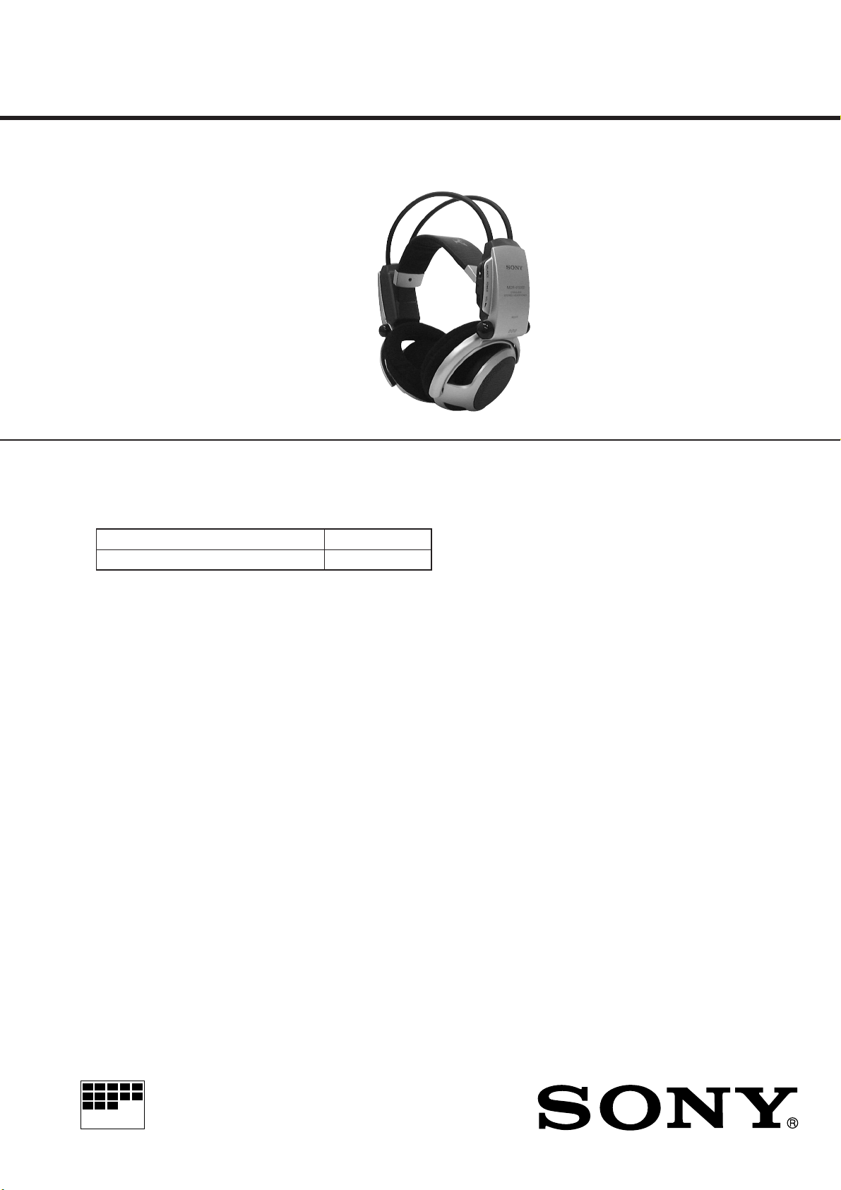
MDR-IF5000
SERVICE MANUAL
Ver 1.0 1998. 11
MDR-IF5000 is the component model block one in
•
MDR-DS5000.
COMPONENT MODEL NAME FOR MDR-DS5000
DIGITAL SURROUND PROCESSOR DP-IF5000
CORDLESS STEREO HEADPHONES MDR-IF5000
E Model
SPECIFICATIONS
Modulation System Frequency modulation
Carrier wave frequency Right channel 2.8 MHz
Left channel 2.3 MHz
Frequency response 12 – 24,000 Hz
Power requirements Rechargeable Ni-Cd
batteries (supplied) or
R6 (size AA) batteries
(dry-cell or
rechargeable, sold
separately)
Mass Approx. 280 g
(including the
supplied rechargeable
Ni-Cd batteries)
Design and specifications are subject to
change without notice.
Notes on Chip Component Replacement
• Never reuse a disconnected chip component.
• Notice that the minus side of a tantalum capacitor may be
damaged by heat.
CORDLESS STEREO HEADPHONES
MICROFILM
– 1 –
Page 2

– 2 –
SECTION 1
GENERAL
This section is extracted
from instruction manual.
Page 3

– 3 –
Page 4
SECTION 2
t
)
DISASSEMBLY
• The equipment can be removed using the following procedure.
Set Frame assy
Hanger (L)
Band Assy, Head
Frame assy
Hanger (R)
Band Assy, HeadRX board
Note : Follow the disassembly procedure in the numerical order given.
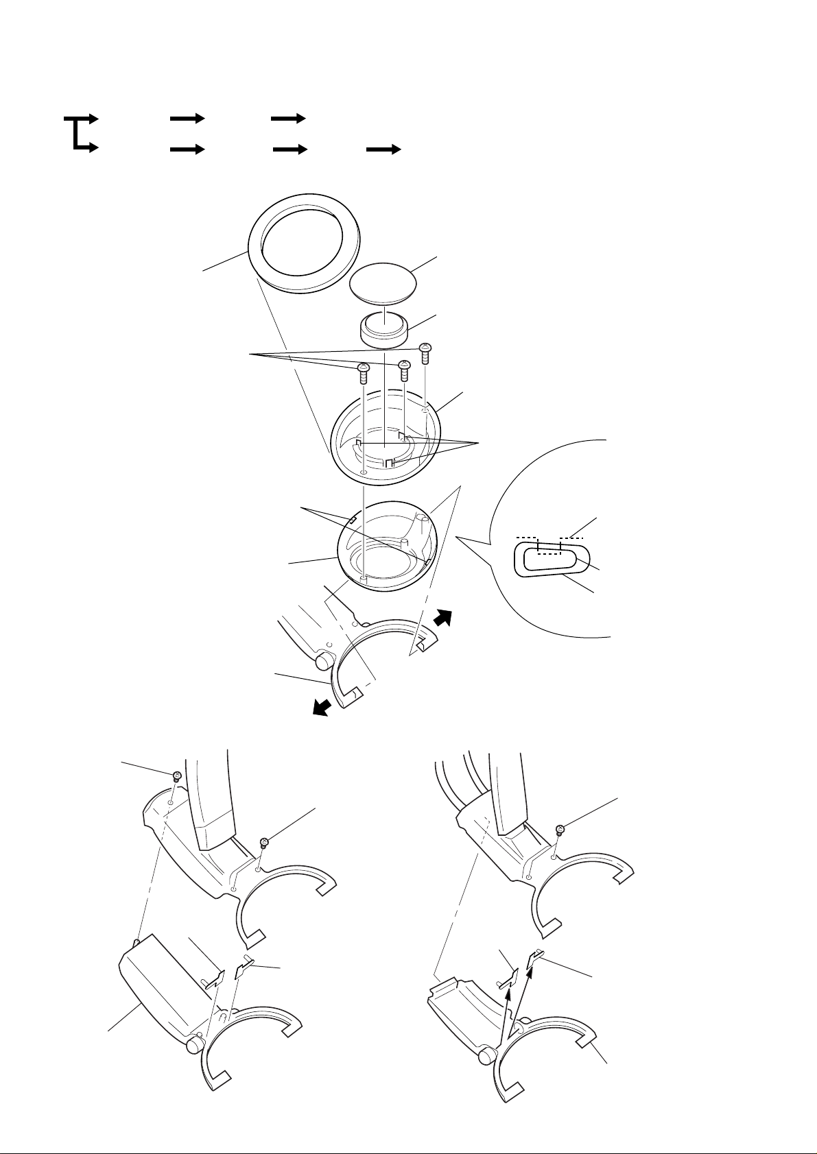
2-1. FRAME ASSY
• Remove the left and right ear
pads in the same manner.
1
pad (outer), ear
5
P 2.6X6
6
claws
2
pad (inner), ear
4
driver assy
7
plate, front
3
claws
plate, fron
8
frame assy
spread
9
hanger
spread
2-2. HANGER (L) 2-3. HANGER (R)
2
P 2.6X6
1
P 2.6X6
4
5
RX PD2
board (L-CH)
4
RX PD1 board (L-CH
RX PD2
board
(R-CH)
hanger
frame assy
1
P 2.6X6
3
RX PD1 board (R-CH)
3
hanger (L)
– 4 –
2
hanger (R)
Page 5

2-4. RX BOARD
1
P 2.6X6
2
RX board
2-5. BAND ASSY, HEAD
5
band assy, head
4
claws
3
stopper, PC board
2
RX SW board
1
wire
When installing,
take care to avoid extrusion
of wire from the hanger.
– 5 –
Page 6

SECTION 3
)
–
r
ELECTRICAL ADJUSTMENTS
Notes:
1. These adjustments are performed in the order that they are
discribed.
2. Adjustment and measurement are performed for each channel
unless otherwise specified.
3. Adjustment is made for right channel first and then the left
channel.
4. The power voltage at the headphones section is supplied with
1.2 V.
5. The processor section is used as jig to adjust the headphones
section (MDR-IF5000).
6. Adjustment is made with the RX SW board and RX PD1 and
RX PD2 boards (for both L-ch and R-ch) connected to the RX
board with wires (normal part).
0 dB=0.775 V
Tuning Adjustment
Preparation:
processor
(DP-IF5000)
headphones
(MDR-IF5000
Adjustment Location:
TP9
TP11
TUNING
ADJUSTMENT
(L-ch)
TUNING
ADJUSTMENT
(R-ch)
L34
L35
L54
L55
– RX board (component side)
1. Set the processor section (DP-IF5000) in test mode and operate
the set to generate a signal of 1 kHz and –10 dB. (Refer to
DP-IF5000 service manual page 7.)
2. Supply 1.2 V to between VCC and ground on the RX board.
3. Adjust RV11 (volume control) on the RX board to the minimum
level.
Setting:
distortion mete
RX board
TP11 (L-ch)
TP9 (R-ch)
+
–
1. Connect a distortion meter to TP11 (L-ch) and TP9 (R-ch) on
the RX board.
2. Adjust L34 and 35 for L-ch and L54 and 55 for R-ch on the
RX board so that the reading on the distortion meter is
minimized.
– 6 –
Page 7

4-1. BLOCK DIAGRAM
B+
(+3.0V)
SECTION 4
DIAGRAMS
L34,35
TUNING
(L)
QUAD COIL
8
AUDIO (L) MIXER LIMITER
IC31
SQUELCH TRIGGER
WITH
HYSTERESIS
MUTE
MDR-IF5000
14
INFRARED
SENSOR
D1-4
04
B+
(+1.7V)
RF AMP
Q1-3
BUFFER
Q4
B+
(+3.0V)
BPF
L54,55
TUNING
GND
AF
AMP
AF
AMP
OUT
VCC
OUT
MUTE
GND
VCC
15
AF
-1
L
B+
4
(+3.0V)
RV10
BALANCE
RV11
VOL
AF
B+
(+1.8V)
B+
(+1.7V)
-2
R
9
14
15
4
(+3.0V)
D10
POWER
++
B+
++
(POWER)
S10
VIN
4
3
FC1
FC2
2
VCC
6
VIN
4
3
FC1
FC2
2
VCC
6
DRIVER AMP (L-CH)
IC32
–
+
–
+
BIAS
CIRCUIT
DRIVER AMP (R-CH)
IC52
–
+
–
+
BIAS
CIRCUIT
DRY BATTERY
SIZE "AA"
(IEC DESIGNATION R6)
2PCS, 3V
NICKEL CADMIUM
BATTERY
(NC-AA)
700mAh 2.4V
VO1
VO2
VO1
VO2
5
8
5
8
SP31
L-CH
SP51
R-CH
• Signal path
: RF
OR
: ANALOG
OSC
2
OSC
OSCILLATOR
1
MIXER
16
16
1
2
8
IN
MIXER
IN
OSC
OSC
QUAD COIL
OSCILLATOR
BPF
(R)
MIXER
MIXER DEMODULATOR
MIXER
OUT
MIXER
OUT
AUDIO (R) MIXER LIMITER
2.3MHz BPF
3 5 9
L33
2.8MHz BPF
3 5
L53
IC51
LIMITER
IN
LIMITER
AMP
LIMITER
IN
LIMITER
AMP
SQUELCH TRIGGER
WITH
HYSTERESIS
DEMODULATOR
– 7 – – 8 –
Page 8
MDR-IF5000
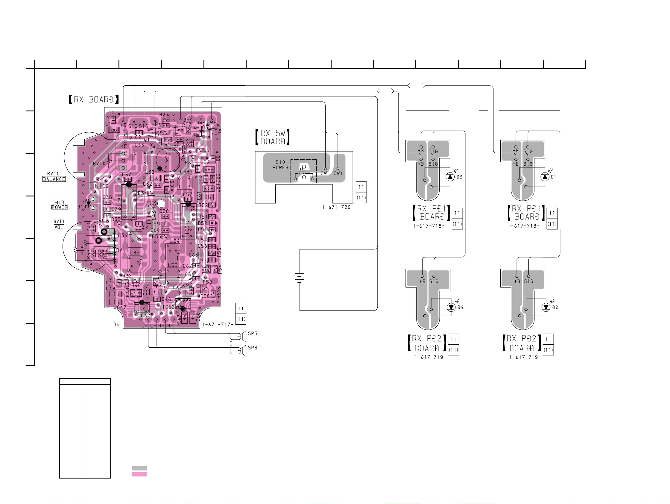
4-2. PRINTED WIRING BOARDS
A
B
C
D
E
F
1
-2
R
2345678910111213
L-CH
INFRARED
SENSOR
-1
L TP11
TP9
( )
DRY BATTERY
SIZE "AA"
(IEC DESIGNATION R6)
2PCS, 3V
OR
NICKEL CADMIUM
BATTERY
(NC-AA)
700mAh 2.4V
R-CH
B+
GND
G
• Semiconductor
Location
Ref. No. Location
D1 C-13
D2 F-13
D3 C-10
D4 F-10
D10 D-2
D51 D-5
D52 D-5
IC31 D-3
IC32 F-3
IC51 D-4
IC52 F-4
Q1 B-3
Q2 B-4
Q3 B-4
Q4 B-5
Note:
• X : parts extracted from the component side.
®
•
• : Pattern from the side which enables seeing.
• : Pattern of the rear side.
: Through hole.
– 9 – – 10 –
R-CH
L-CH
Page 9

4-3. SCHEMATIC DIAGRAM • Refer to page 13 for IC Block Diagrams.
MDR-IF5000
– 11 –
Note:
• All capacitors are in µF unless otherwise noted. pF: µµF
50 WV or less are not indicated except for electrolytics
and tantalums.
• All resistors are in Ω and 1/
specified.
¢
•
• C : panel designation.
• U : B+ Line.
• H : adjustment for repair.
• Power voltage is dc 3 V and fed with regulated dc power
: internal component.
supply from battery terminal.
4
W or less unless otherwise
• Total current is measured with POWER ON (no-signal) mode.
• Voltage is dc with respect to ground under no-signal
condition.
no mark : POWER ON
• Voltages are taken with a VOM (Input impedance 10 MΩ).
Voltage variations may be noted due to normal production tolerances.
• Signal path.
J : RF
F : ANALOG
– 12 –
Page 10

• IC Block Diagrams
IC31, 51 SC111711DR2
MIXER
INPUT
SCAN
GND MUTE
1516 14 13 12 11 10 9
SQUELCH TRIGGER WITH
HYSTERESIS
CONTROL
SQUELCHINFILTER
OUTPUT
FILTER
AMP
FILTER
INPUT
–
+
RECOVERD
AUDIO
+
AMP
AF
MIXER
OSCILLATOR
1 2 3 4 7 865
CRYSTAL
OSC
MIXER
OUTPUT
VCC
LIMITER
INPUT
IC32, 52 MC34119DTBEL
VO2
GND
Vcc
8 7 6 5
_
+
BIAS
CIRCUIT
LIMITER
AMP
DECOUPLING
+
_
DEMODULATOR
QUAD
VO1
COIL
4321
CD
CF 2
CF 1
V in
– 13 –
Page 11

NOTE:
• The mechanical parts with no reference
number in the exploded views are not supplied.
• Items marked “*” are not stocked since
they are seldom required for routine service.
Some delay should be anticipated
when ordering these items.
9
10
11
12
SECTION 5
EXPLODED VIEW
• -XX and -X mean standardized parts, so
they may have some difference from the
original one.
• Color Indication of Appearance Parts
Example :
KNOB, BALANCE (WHITE) ... (RED)
13
14
4
N
Parts Color Cabinet’s Color
3
N
2
1
22
26
not supplied
20
3
14
28
27
18
3
3
24
6
26
17
19
15
16
14
25
14
3
7
SP31
8
SP51
3
22
5
3
3
8
7
23
21
1 X-4951-063-1 BAND (F) ASSY, HEAD
2 X-4951-064-1 BAND (R) ASSY, HEAD
3 7-685-104-19 SCREW +P 2X6 TYPE2 NON-SLIT
4 X-4951-014-1 SUSPENDER ASSY
5 4-213-919-01 PLATE (L), FRONT
6 X-4950-548-1 FRAME (L) ASSY
7 4-213-911-01 PAD (OUTER), EAR
8 4-213-910-01 PAD (INNER), EAR
9 4-213-900-01 LID, BATTERY
10 4-961-876-01 TERMINAL (COMMONNESS), BATTERY
11 4-214-464-01 TERMINAL, (-) BATTERY
12 4-961-874-01 TERMINAL, (+) BATTERY
13 4-213-896-01 HANGER (L)
14 4-213-901-01 WINDOW, RAY CATCHER
* 15 1-671-718-11 RX PD1 BOARD (L-CH)
Ref. No. Part No. Description RemarkRef. No. Part No. Description Remark
* 16 1-671-719-11 RX PD2 BOARD (L-CH)
17 X-4951-066-1 LID (L) ASSY, HANGER
18 4-213-918-01 SPRING, TENSION
* 19 1-671-720-11 RX SW BOARD
* 20 A-4542-557-A RX BOARD, COMPLETE
21 X-4950-549-1 FRAME (R) ASSY
22 4-213-916-01 SCREEN
23 4-213-920-01 PLATE (R), FRONT
24 4-213-897-01 HANGER (R)
25 4-213-899-01 LID (R), HANGER
26 4-215-827-01 STOPPER, BAND
* 27 1-671-718-11 RX PD1 BOARD (R-CH)
* 28 1-671-719-11 RX PD2 BOARD (R-CH)
SP31 X-4951-065-1 DRIVER ASSY (L-CH)
SP51 X-4951-065-1 DRIVER ASSY (R-CH)
– 14 –
Page 12

SECTION 6
ELECTRICAL PARTS LIST
NOTE:
• Due to standardization, replacements in
the parts list may be different from the
parts specified in the diagrams or the
components used on the set.
• -XX and -X mean standardized parts, so
they may have some difference from the
original one.
• RESISTORS
All resistors are in ohms.
MET AL:Metal-film resistor.
METAL OXIDE: Metal oxide-film resistor.
F:nonflammable
Ref. No. Part No. Description Remark Ref. No. Part No. Description Remark
* A-4542-557-A RX BOARD, COMPLETE
*******************
< CAPACITOR >
• Items marked “*” are not stocked since
they are seldom required for routine service.
Some delay should be anticipated
when ordering these items.
• SEMICONDUCTORS
In each case, u : µ, for example:
uA.. : µA.. uP A.. : µPA..
uPB.. : µPB.. uPC.. : µPC.. uPD.. : µPD..
• CAP A CIT ORS
uF : µF
• COILS
uH : µH
C65 1-135-201-11 TANTALUM CHIP 10uF 20% 4V
C66 1-163-033-11 CERAMIC CHIP 0.022uF 50V
C67 1-135-201-11 TANTALUM CHIP 10uF 20% 4V
C68 1-135-180-21 TANTALUM CHIP 3.3uF 20% 6.3V
When indicating parts by reference
number, please include the board.
RX
C1 1-163-031-11 CERAMIC CHIP 0.01uF 50V
C2 1-163-243-11 CERAMIC CHIP 47PF 5% 50V
C3 1-163-031-11 CERAMIC CHIP 0.01uF 50V
C4 1-163-031-11 CERAMIC CHIP 0.01uF 50V
C5 1-163-031-11 CERAMIC CHIP 0.01uF 50V
C6 1-164-346-11 CERAMIC CHIP 1uF 16V
C7 1-126-246-11 ELECT CHIP 220uF 20% 4V
C8 1-164-346-11 CERAMIC CHIP 1uF 16V
C9 1-135-201-11 TANTALUM CHIP 10uF 20% 4V
C30 1-163-117-00 CERAMIC CHIP 100PF 5% 50V
C31 1-163-021-11 CERAMIC CHIP 0.01uF 10% 50V
C32 1-163-251-11 CERAMIC CHIP 100PF 5% 50V
C33 1-163-106-00 CERAMIC CHIP 36PF 5% 50V
C34 1-164-346-11 CERAMIC CHIP 1uF 16V
C37 1-163-031-11 CERAMIC CHIP 0.01uF 50V
C38 1-163-031-11 CERAMIC CHIP 0.01uF 50V
C39 1-163-031-11 CERAMIC CHIP 0.01uF 50V
C40 1-163-031-11 CERAMIC CHIP 0.01uF 50V
C42 1-117-720-11 CERAMIC CHIP 4.7uF 10V
C43 1-163-809-11 CERAMIC CHIP 0.047uF 10% 25V
C44 1-117-720-11 CERAMIC CHIP 4.7uF 10V
C45 1-135-201-11 TANTALUM CHIP 10uF 20% 4V
C46 1-163-033-11 CERAMIC CHIP 0.022uF 50V
C47 1-135-201-11 TANTALUM CHIP 10uF 20% 4V
C48 1-135-180-21 TANTALUM CHIP 3.3uF 20% 6.3V
C50 1-163-117-00 CERAMIC CHIP 100PF 5% 50V
C51 1-163-021-11 CERAMIC CHIP 0.01uF 10% 50V
C52 1-163-121-00 CERAMIC CHIP 150PF 5% 50V
C53 1-163-031-11 CERAMIC CHIP 0.01uF 50V
C54 1-163-031-11 CERAMIC CHIP 0.01uF 50V
< DIODE >
D10 8-719-066-57 LED SA2512 (POWER)
D51 8-719-421-40 DIODE MA77
D52 8-719-421-40 DIODE MA77
< IC >
IC31 8-759-473-72 IC SC111711DR2
IC32 8-759-463-98 IC MC34119DR2
IC51 8-759-473-72 IC SC111711DR2
IC52 8-759-463-98 IC MC34119DR2
< COIL >
L1 1-412-956-21 INDUCTOR 27uH
L32 1-412-957-11 INDUCTOR 33uH
L33 1-239-762-11 FILTER, BAND PASS
L34 1-416-885-11 COIL, DETECTION (A)
L35 1-416-886-11 COIL, DETECTION (B)
L51 1-412-959-11 INDUCTOR 47uH
L52 1-412-957-11 INDUCTOR 33uH
L53 1-239-763-11 FILTER, BAND PASS
L54 1-416-887-11 COIL, DETECTION (A)
L55 1-416-888-11 COIL, DETECTION (B)
< TRANSISTOR >
Q1 8-729-220-93 FET 2SK209-G
Q2 8-729-024-13 TRANSISTOR 2SA1256E4
Q3 8-729-809-77 TRANSISTOR 2SC3142-J4
Q4 8-729-216-22 TRANSISTOR 2SA1162-G
< RESISTOR >
C55 1-163-123-00 CERAMIC CHIP 180PF 5% 50V
C56 1-163-123-00 CERAMIC CHIP 180PF 5% 50V
C57 1-163-031-11 CERAMIC CHIP 0.01uF 50V
C58 1-163-031-11 CERAMIC CHIP 0.01uF 50V
C59 1-163-031-11 CERAMIC CHIP 0.01uF 50V
C60 1-163-031-11 CERAMIC CHIP 0.01uF 50V
C61 1-135-149-21 TANTALUM CHIP 2.2uF 20% 10V
C62 1-117-720-11 CERAMIC CHIP 4.7uF 10V
C63 1-163-809-11 CERAMIC CHIP 0.047uF 10% 25V
C64 1-117-720-11 CERAMIC CHIP 4.7uF 10V
R1 1-216-057-00 METAL CHIP 2.2K 5% 1/10W
R2 1-216-049-11 RES,CHIP 1K 5% 1/10W
R3 1-216-097-00 RES,CHIP 100K 5% 1/10W
R4 1-216-093-00 RES,CHIP 68K 5% 1/10W
R5 1-216-049-11 RES,CHIP 1K 5% 1/10W
R6 1-216-057-00 METAL CHIP 2.2K 5% 1/10W
R7 1-216-037-00 METAL CHIP 330 5% 1/10W
R8 1-216-001-00 METAL CHIP 10 5% 1/10W
R34 1-216-063-00 RES,CHIP 3.9K 5% 1/10W
R35 1-216-063-00 RES,CHIP 3.9K 5% 1/10W
– 15 –
Page 13

MDR-IF5000
RX RX PD1 RX PD2 RX SW
Ref. No. Part No. Description Remark Ref. No. Part No. Description Remark
R36 1-216-049-11 RES,CHIP 1K 5% 1/10W
R37 1-216-073-00 METAL CHIP 10K 5% 1/10W
R38 1-216-089-00 RES,CHIP 47K 5% 1/10W
R39 1-216-063-00 RES,CHIP 3.9K 5% 1/10W
R40 1-216-063-00 RES,CHIP 3.9K 5% 1/10W
R51 1-216-037-00 METAL CHIP 330 5% 1/10W
R52 1-216-097-00 RES,CHIP 100K 5% 1/10W
R53 1-216-111-00 METAL CHIP 390K 5% 1/10W
R54 1-216-061-00 METAL CHIP 3.3K 5% 1/10W
R55 1-216-063-00 RES,CHIP 3.9K 5% 1/10W
R56 1-216-049-11 RES,CHIP 1K 5% 1/10W
R57 1-216-073-00 METAL CHIP 10K 5% 1/10W
R58 1-216-089-00 RES,CHIP 47K 5% 1/10W
R59 1-216-063-00 RES,CHIP 3.9K 5% 1/10W
R60 1-216-069-00 METAL CHIP 6.8K 5% 1/10W
< VARIABLE RESISTOR >
RV10 1-223-516-11 RES, VAR, CARBON 50K (BALANCE)
RV11 1-223-517-11 RES, VAR, CARBON 50K/50K (VOL)
*************************************************************
* 1-671-720-11 RX SW BOARD
************
< SWITCH >
S10 1-572-467-61 SWITCH, PUSH (1 KEY) (POWER)
*************************************************************
MISCELLANEOUS
***************
SP31 X-4951-065-1 DRIVER ASSY (L-CH)
SP51 X-4951-065-1 DRIVER ASSY (R-CH)
* 1-671-718-11 RX PD1 BOARD (L-CH)
*************
< PHOTO DIODE >
D1 8-719-058-49 PHOTO DIODE PP508
*************************************************************
* 1-671-718-11 RX PD1 BOARD (R-CH)
D3 8-719-058-49 PHOTO DIODE PP508
*************************************************************
* 1-671-719-11 RX PD2 BOARD (L-CH)
D2 8-719-058-49 PHOTO DIODE PP508
*************************************************************
* 1-671-719-11 RX PD2 BOARD (R-CH)
*************
< PHOTO DIODE >
*************
< PHOTO DIODE >
*************
< PHOTO DIODE >
D4 8-719-058-49 PHOTO DIODE PP508
*************************************************************
Sony Corporation
9-924-998-11
Personal A&V Products Company
– 16 –
Printed in Singapore C1998. 12
98L047015-1
Published by Quality Engineering Dept.
(Shibaura)
Page 14
MDR-IF5000
SERVICE MANUAL
Ver 1.1 1999. 02
MDR-IF5000 is the component model block one in
•
MDR-DS5000.
COMPONENT MODEL NAME FOR MDR-DS5000
DIGITAL SURROUND PROCESSOR DP-IF5000
CORDLESS STEREO HEADPHONES MDR-IF5000
US Model
Canadian Model
AEP Model
UK Model
E Model
SPECIFICATIONS
Modulation System Frequency modulation
Carrier wave frequency Right channel 2.8 MHz
Left channel 2.3 MHz
Frequency response 12 – 24,000 Hz
Power requirements Rechargeable Ni-Cd
batteries (supplied) or
R6 (size AA) batteries
(dry-cell or
rechargeable, sold
separately)
Mass Approx. 280 g
(including the
supplied rechargeable
Ni-Cd batteries)
Design and specifications are subject to
change without notice.
Notes on Chip Component Replacement
• Never reuse a disconnected chip component.
• Notice that the minus side of a tantalum capacitor may be
damaged by heat.
CORDLESS STEREO HEADPHONES
MICROFILM
– 1 –
Page 15

– 2 –
SECTION 1
GENERAL
This section is extracted
from instruction manual.
Page 16

– 3 –
Page 17

SECTION 2
t
)
DISASSEMBLY
• The equipment can be removed using the following procedure.
Set Frame assy
Hanger (L)
Band Assy, Head
Frame assy
Hanger (R)
Band Assy, HeadRX board
Note : Follow the disassembly procedure in the numerical order given.
2-1. FRAME ASSY
• Remove the left and right ear
pads in the same manner.
1
pad (outer), ear
5
P 2.6X6
6
claws
2
pad (inner), ear
4
driver assy
7
plate, front
3
claws
plate, fron
8
frame assy
spread
9
hanger
spread
2-2. HANGER (L) 2-3. HANGER (R)
2
P 2.6X6
1
P 2.6X6
4
5
RX PD2
board (L-CH)
4
RX PD1 board (L-CH
RX PD2
board
(R-CH)
hanger
frame assy
1
P 2.6X6
3
RX PD1 board (R-CH)
3
hanger (L)
– 4 –
2
hanger (R)
Page 18

2-4. RX BOARD
1
P 2.6X6
2
RX board
2-5. BAND ASSY, HEAD
5
band assy, head
4
claws
3
stopper, PC board
2
RX SW board
1
wire
When installing,
take care to avoid extrusion
of wire from the hanger.
– 5 –
Page 19

SECTION 3
)
–
r
ELECTRICAL ADJUSTMENTS
Notes:
1. These adjustments are performed in the order that they are
discribed.
2. Adjustment and measurement are performed for each channel
unless otherwise specified.
3. Adjustment is made for right channel first and then the left
channel.
4. The power voltage at the headphones section is supplied with
1.2 V.
5. The processor section is used as jig to adjust the headphones
section (MDR-IF5000).
6. Adjustment is made with the RX SW board and RX PD1 and
RX PD2 boards (for both L-ch and R-ch) connected to the RX
board with wires (normal part).
0 dB=0.775 V
Tuning Adjustment
Preparation:
processor
(DP-IF5000)
headphones
(MDR-IF5000
Adjustment Location:
TP9
TP11
TUNING
ADJUSTMENT
(L-ch)
TUNING
ADJUSTMENT
(R-ch)
L34
L35
L54
L55
– RX board (component side)
1. Set the processor section (DP-IF5000) in test mode and operate
the set to generate a signal of 1 kHz and –10 dB. (Refer to
DP-IF5000 service manual page 7.)
2. Supply 1.2 V to between VCC and ground on the RX board.
3. Adjust RV11 (volume contr ol) on the RX board to the minimum
level.
Setting:
distortion mete
RX board
TP11 (L-ch)
TP9 (R-ch)
+
–
1. Connect a distortion meter to TP11 (L-ch) and TP9 (R-ch) on
the RX board.
2. Adjust L34 and 35 for L-ch and L54 and 55 for R-ch on the
RX board so that the reading on the distortion meter is
minimized.
– 6 –
Page 20

4-1. BLOCK DIAGRAM
B+
(+3.0V)
SECTION 4
DIAGRAMS
L34,35
TUNING
(L)
QUAD COIL
8
AUDIO (L) MIXER LIMITER
IC31
SQUELCH TRIGGER
WITH
HYSTERESIS
MUTE
MDR-IF5000
14
INFRARED
SENSOR
D1-4
04
B+
(+1.7V)
RF AMP
Q1-3
BUFFER
Q4
B+
(+3.0V)
BPF
L54,55
TUNING
GND
AF
AMP
AF
AMP
OUT
VCC
OUT
MUTE
GND
VCC
15
AF
-1
L
B+
4
(+3.0V)
RV10
BALANCE
RV11
VOL
AF
B+
(+1.8V)
B+
(+1.7V)
-2
R
9
14
15
4
(+3.0V)
D10
POWER
++
B+
++
(POWER)
S10
VIN
4
3
FC1
FC2
2
VCC
6
VIN
4
3
FC1
FC2
2
VCC
6
DRIVER AMP (L-CH)
IC32
–
+
–
+
BIAS
CIRCUIT
DRIVER AMP (R-CH)
IC52
–
+
–
+
BIAS
CIRCUIT
DRY BATTERY
SIZE "AA"
(IEC DESIGNATION R6)
2PCS, 3V
NICKEL CADMIUM
BATTERY
(NC-AA)
700mAh 2.4V
VO1
VO2
VO1
VO2
5
8
5
8
SP31
L-CH
SP51
R-CH
• Signal path
: RF
OR
: ANALOG
OSC
2
OSC
OSCILLATOR
1
MIXER
16
16
1
2
8
IN
MIXER
IN
OSC
OSC
QUAD COIL
OSCILLATOR
BPF
(R)
MIXER
MIXER DEMODULATOR
MIXER
OUT
MIXER
OUT
AUDIO (R) MIXER LIMITER
2.3MHz BPF
3 5 9
L33
2.8MHz BPF
3 5
L53
IC51
LIMITER
IN
LIMITER
AMP
LIMITER
IN
LIMITER
AMP
SQUELCH TRIGGER
WITH
HYSTERESIS
DEMODULATOR
– 7 – – 8 –
Page 21

MDR-IF5000
4-2. PRINTED WIRING BOARDS
A
B
C
D
E
F
1
-2
R
2345678910111213
L-CH
INFRARED
SENSOR
-1
L TP11
TP9
( )
DRY BATTERY
SIZE "AA"
(IEC DESIGNATION R6)
2PCS, 3V
OR
NICKEL CADMIUM
BATTERY
(NC-AA)
700mAh 2.4V
R-CH
B+
GND
G
• Semiconductor
Location
Ref. No. Location
D1 C-13
D2 F-13
D3 C-10
D4 F-10
D10 D-2
D51 D-5
D52 D-5
IC31 D-3
IC32 F-3
IC51 D-4
IC52 F-4
Q1 B-3
Q2 B-4
Q3 B-4
Q4 B-5
Note:
• X : parts extracted from the component side.
®
•
• : Pattern from the side which enables seeing.
• : Pattern of the rear side.
: Through hole.
– 9 – – 10 –
R-CH
L-CH
Page 22

4-3. SCHEMATIC DIAGRAM • Refer to page 13 for IC Block Diagrams.
MDR-IF5000
– 11 –
Note:
• All capacitors are in µF unless otherwise noted. pF: µµF
50 WV or less are not indicated except for electrolytics
and tantalums.
• All resistors are in Ω and 1/
specified.
¢
•
• C : panel designation.
• U : B+ Line.
• H : adjustment for repair.
• Power voltage is dc 3 V and fed with regulated dc power
: internal component.
supply from battery terminal.
4
W or less unless otherwise
• Total current is measured with POWER ON (no-signal) mode.
• Voltage is dc with respect to ground under no-signal
condition.
no mark : POWER ON
• Voltages are taken with a VOM (Input impedance 10 MΩ).
Voltage variations may be noted due to normal production tolerances.
• Signal path.
J : RF
F : ANALOG
– 12 –
Page 23

SECTION 5
EXPLODED VIEW
• IC Block Diagrams
IC31, 51 SC111711DR2
MIXER
INPUT
OSCILLATOR
1 2 3 4 7 865
CRYSTAL
IC32, 52 MC34119DTBEL
VO2
8 7 6 5
BIAS
CIRCUIT
SCAN
GND MUTE
1516 14 13 12 11 10 9
SQUELCH TRIGGER WITH
HYSTERESIS
MIXER
MIXER
GND
OUTPUT
Vcc
CF 2
OSC
CD
CONTROL
VCC
_
+
SQUELCHINFILTER
OUTPUT
LIMITER
AMP
LIMITER
INPUT
CF 1
DECOUPLING
+
_
4321
V in
FILTER
AMP
FILTER
RECOVERD
INPUT
–
+
DEMODULATOR
VO1
AUDIO
+
QUAD
COIL
AF
AMP
NOTE:
• The mechanical parts with no reference
number in the exploded views are not supplied.
• Items marked “*” are not stocked since
they are seldom required for routine service.
Some delay should be anticipated
when ordering these items.
9
10
11
14
6
26
22
5
28
12
3
• -XX and -X mean standardized parts, so
they may have some difference from the
original one.
• Color Indication of Appearance Parts
Example :
KNOB, BALANCE (WHITE) ... (RED)
Parts Color Cabinet’s Color
13
14
4
3
27
3
3
17
25
7
3
SP31
8
8
SP51
3
7
N
19
N
2
1
26
18
not supplied
20
3
24
16
15
14
14
3
22
23
21
Ref. No. Part No. Description RemarkRef. No. Part No. Description Remark
1 X-4951-063-1 BAND (F) ASSY, HEAD
* 16 1-671-719-11 RX PD2 BOARD (L-CH)
2 X-4951-064-1 BAND (R) ASSY, HEAD
3 7-685-104-19 SCREW +P 2X6 TYPE2 NON-SLIT
4 X-4951-014-1 SUSPENDER ASSY
5 4-213-919-01 PLATE (L), FRONT
* 19 1-671-720-11 RX SW BOARD
* 20 A-4542-557-A RX BOARD, COMPLETE
6 X-4950-548-1 FRAME (L) ASSY
7 4-213-911-01 PAD (OUTER), EAR
8 4-213-910-01 PAD (INNER), EAR
9 4-213-900-01 LID, BATTERY
10 4-961-876-01 TERMINAL (COMMONNESS), BATTERY
11 4-214-464-01 TERMINAL, (-) BATTERY
12 4-961-874-01 TERMINAL, (+) BATTERY
13 4-213-896-01 HANGER (L)
* 27 1-671-718-11 RX PD1 BOARD (R-CH)
* 28 1-671-719-11 RX PD2 BOARD (R-CH)
14 4-213-901-01 WINDOW, RAY CATCHER
* 15 1-671-718-11 RX PD1 BOARD (L-CH)
– 13 – – 14 –
17 X-4951-066-1 LID (L) ASSY, HANGER
18 4-213-918-01 SPRING, TENSION
21 X-4950-549-1 FRAME (R) ASSY
22 4-213-916-01 SCREEN
23 4-213-920-01 PLATE (R), FRONT
24 4-213-897-01 HANGER (R)
25 4-213-899-01 LID (R), HANGER
26 4-215-827-01 STOPPER, BAND
SP31 X-4951-065-1 DRIVER ASSY (L-CH)
SP51 X-4951-065-1 DRIVER ASSY (R-CH)
Page 24

SECTION 6
ELECTRICAL PARTS LIST
NOTE:
• Due to standardization, replacements in
the parts list may be different from the
parts specified in the diagrams or the
components used on the set.
• -XX and -X mean standardized parts, so
they may have some difference from the
original one.
• RESISTORS
All resistors are in ohms.
MET AL:Metal-film resistor.
METAL OXIDE: Metal oxide-film resistor.
F:nonflammable
Ref. No. Part No. Description Remark Ref. No. Part No. Description Remark
* A-4542-557-A RX BOARD, COMPLETE
*******************
< CAPACITOR >
• Items marked “*” are not stocked since
they are seldom required for routine service.
Some delay should be anticipated
when ordering these items.
• SEMICONDUCTORS
In each case, u : µ, for example:
uA.. : µA.. uPA.. : µPA..
uPB.. : µPB.. uPC.. : µPC.. uPD.. : µPD..
• CAPACITORS
uF : µF
• COILS
uH : µH
C65 1-135-201-11 TANTALUM CHIP 10uF 20% 4V
C66 1-163-033-11 CERAMIC CHIP 0.022uF 50V
C67 1-135-201-11 TANTALUM CHIP 10uF 20% 4V
C68 1-135-180-21 TANTALUM CHIP 3.3uF 20% 6.3V
When indicating parts by reference
number, please include the board.
RX
C1 1-163-031-11 CERAMIC CHIP 0.01uF 50V
C2 1-163-243-11 CERAMIC CHIP 47PF 5% 50V
C3 1-163-031-11 CERAMIC CHIP 0.01uF 50V
C4 1-163-031-11 CERAMIC CHIP 0.01uF 50V
C5 1-163-031-11 CERAMIC CHIP 0.01uF 50V
C6 1-164-346-11 CERAMIC CHIP 1uF 16V
C7 1-126-246-11 ELECT CHIP 220uF 20% 4V
C8 1-164-346-11 CERAMIC CHIP 1uF 16V
C9 1-135-201-11 TANTALUM CHIP 10uF 20% 4V
C30 1-163-117-00 CERAMIC CHIP 100PF 5% 50V
C31 1-163-021-11 CERAMIC CHIP 0.01uF 10% 50V
C32 1-163-251-11 CERAMIC CHIP 100PF 5% 50V
C33 1-163-106-00 CERAMIC CHIP 36PF 5% 50V
C34 1-164-346-11 CERAMIC CHIP 1uF 16V
C37 1-163-031-11 CERAMIC CHIP 0.01uF 50V
C38 1-163-031-11 CERAMIC CHIP 0.01uF 50V
C39 1-163-031-11 CERAMIC CHIP 0.01uF 50V
C40 1-163-031-11 CERAMIC CHIP 0.01uF 50V
C42 1-117-720-11 CERAMIC CHIP 4.7uF 10V
C43 1-163-809-11 CERAMIC CHIP 0.047uF 10% 25V
C44 1-117-720-11 CERAMIC CHIP 4.7uF 10V
C45 1-135-201-11 TANTALUM CHIP 10uF 20% 4V
C46 1-163-033-11 CERAMIC CHIP 0.022uF 50V
C47 1-135-201-11 TANTALUM CHIP 10uF 20% 4V
C48 1-135-180-21 TANTALUM CHIP 3.3uF 20% 6.3V
C50 1-163-117-00 CERAMIC CHIP 100PF 5% 50V
C51 1-163-021-11 CERAMIC CHIP 0.01uF 10% 50V
C52 1-163-121-00 CERAMIC CHIP 150PF 5% 50V
C53 1-163-031-11 CERAMIC CHIP 0.01uF 50V
C54 1-163-031-11 CERAMIC CHIP 0.01uF 50V
< DIODE >
D10 8-719-066-57 LED SA2512 (POWER)
D51 8-719-421-40 DIODE MA77
D52 8-719-421-40 DIODE MA77
< IC >
IC31 8-759-473-72 IC SC111711DR2
IC32 8-759-463-98 IC MC34119DR2
IC51 8-759-473-72 IC SC111711DR2
IC52 8-759-463-98 IC MC34119DR2
< COIL >
L1 1-412-956-21 INDUCTOR 27uH
L32 1-412-957-11 INDUCTOR 33uH
L33 1-239-762-11 FILTER, BAND PASS
L34 1-416-885-11 COIL, DETECTION (A)
L35 1-416-886-11 COIL, DETECTION (B)
L51 1-412-959-11 INDUCTOR 47uH
L52 1-412-957-11 INDUCTOR 33uH
L53 1-239-763-11 FILTER, BAND PASS
L54 1-416-887-11 COIL, DETECTION (A)
L55 1-416-888-11 COIL, DETECTION (B)
< TRANSISTOR >
Q1 8-729-220-93 FET 2SK209-G
Q2 8-729-024-13 TRANSISTOR 2SA1256E4
Q3 8-729-809-77 TRANSISTOR 2SC3142-J4
Q4 8-729-216-22 TRANSISTOR 2SA1162-G
< RESISTOR >
C55 1-163-123-00 CERAMIC CHIP 180PF 5% 50V
C56 1-163-123-00 CERAMIC CHIP 180PF 5% 50V
C57 1-163-031-11 CERAMIC CHIP 0.01uF 50V
C58 1-163-031-11 CERAMIC CHIP 0.01uF 50V
C59 1-163-031-11 CERAMIC CHIP 0.01uF 50V
C60 1-163-031-11 CERAMIC CHIP 0.01uF 50V
C61 1-135-149-21 TANTALUM CHIP 2.2uF 20% 10V
C62 1-117-720-11 CERAMIC CHIP 4.7uF 10V
C63 1-163-809-11 CERAMIC CHIP 0.047uF 10% 25V
C64 1-117-720-11 CERAMIC CHIP 4.7uF 10V
R1 1-216-057-00 METAL CHIP 2.2K 5% 1/10W
R2 1-216-049-11 RES,CHIP 1K 5% 1/10W
R3 1-216-097-00 RES,CHIP 100K 5% 1/10W
R4 1-216-093-00 RES,CHIP 68K 5% 1/10W
R5 1-216-049-11 RES,CHIP 1K 5% 1/10W
R6 1-216-057-00 METAL CHIP 2.2K 5% 1/10W
R7 1-216-037-00 METAL CHIP 330 5% 1/10W
R8 1-216-001-00 METAL CHIP 10 5% 1/10W
R34 1-216-063-00 RES,CHIP 3.9K 5% 1/10W
R35 1-216-063-00 RES,CHIP 3.9K 5% 1/10W
– 15 –
Page 25

MDR-IF5000
RX RX PD1 RX PD2 RX SW
Ref. No. Part No. Description Remark Ref. No. Part No. Description Remark
R36 1-216-049-11 RES,CHIP 1K 5% 1/10W
R37 1-216-073-00 METAL CHIP 10K 5% 1/10W
R38 1-216-089-00 RES,CHIP 47K 5% 1/10W
R39 1-216-063-00 RES,CHIP 3.9K 5% 1/10W
R40 1-216-063-00 RES,CHIP 3.9K 5% 1/10W
R51 1-216-037-00 METAL CHIP 330 5% 1/10W
R52 1-216-097-00 RES,CHIP 100K 5% 1/10W
R53 1-216-111-00 METAL CHIP 390K 5% 1/10W
R54 1-216-061-00 METAL CHIP 3.3K 5% 1/10W
R55 1-216-063-00 RES,CHIP 3.9K 5% 1/10W
R56 1-216-049-11 RES,CHIP 1K 5% 1/10W
R57 1-216-073-00 METAL CHIP 10K 5% 1/10W
R58 1-216-089-00 RES,CHIP 47K 5% 1/10W
R59 1-216-063-00 RES,CHIP 3.9K 5% 1/10W
R60 1-216-069-00 METAL CHIP 6.8K 5% 1/10W
< VARIABLE RESISTOR >
RV10 1-223-516-11 RES, VAR, CARBON 50K (BALANCE)
RV11 1-223-517-11 RES, VAR, CARBON 50K/50K (VOL)
*************************************************************
* 1-671-720-11 RX SW BOARD
************
< SWITCH >
S10 1-572-467-61 SWITCH, PUSH (1 KEY) (POWER)
*************************************************************
MISCELLANEOUS
***************
SP31 X-4951-065-1 DRIVER ASSY (L-CH)
SP51 X-4951-065-1 DRIVER ASSY (R-CH)
* 1-671-718-11 RX PD1 BOARD (L-CH)
*************
< PHOTO DIODE >
D1 8-719-058-49 PHOTO DIODE PP508
*************************************************************
* 1-671-718-11 RX PD1 BOARD (R-CH)
D3 8-719-058-49 PHOTO DIODE PP508
*************************************************************
* 1-671-719-11 RX PD2 BOARD (L-CH)
D2 8-719-058-49 PHOTO DIODE PP508
*************************************************************
* 1-671-719-11 RX PD2 BOARD (R-CH)
*************
< PHOTO DIODE >
*************
< PHOTO DIODE >
*************
< PHOTO DIODE >
D4 8-719-058-49 PHOTO DIODE PP508
*************************************************************
Sony Corporation
9-924-998-12
Personal A&V Products Company
– 16 –
Printed in Japan C1999. 2
99B0481-1
Published by Quality Engineering Dept.
(Shinagawa)
 Loading...