

Sony MDR-IF4000 User Manual

MDR-IF4000
SERVICE MANUAL
Ver. 1.1 2005. 02
• The MDR-IF4000 is the cordless stereo
headphones that comprises the MDRDS4000.
• MDR-DS4000 consists of the following models respectively.
Cordless stereo headphone MDR-IF4000
Digital surround processor DP-IF4000
SPECIFICATIONS
US Model
Canadian Model
AEP Model
E Model
General
Modulation System
Secondary carrier wave frequency
Playback frequency range
Power requirements
Supplied accessories
Design and specifications are subject to change without notice.
DQPSK-IM
3.75 MHz
10 – 22,000 Hz
Rechargeable nickel-metal hydride
batteries (supplied) or commercially
available (size AAA) alkaline batteries
Mass Approx. 300 g (11 oz) (including the
supplied rechargeable nickel-metal
hydride batteries)
Rechargeable nickel-metal hydride
batteries
BP-HP550 (550 mAh min.) (2)
Operating Instructions (1)
9-879-301-02
2005B02-1
© 2005.02
CORDLESS STEREO HEADPHONE
Sony Corporation
Personal Audio Company
Published by Sony Engineering Corporation

MDR-IF4000
Notes on chip component replacement
• Never reuse a disconnected chip component.
• Notice that the minus side of a tantalum capacitor may be
damaged by heat.
Unleaded solder
Boards requiring use of unleaded solder are printed with the lead
free mark (LF) indicating the solder contains no lead.
(Caution: Some printed circuit boards may not come printed with
the lead free mark due to their particular size.)
: LEAD FREE MARK
Unleaded solder has the following characteristics.
•Unleaded solder melts at a temperature about 40°C higher than
ordinary solder.
Ordinary soldering irons can be used but the iron tip has to be
applied to the solder joint for a slightly longer time.
Soldering irons using a temperature regulator should be set to
about 350°C.
Caution: The printed pattern (copper foil) may peel away if
the heated tip is applied for too long, so be careful!
• Strong viscosity
Unleaded solder is more viscous (sticky, less prone to flow)
than ordinary solder so use caution not to let solder bridges
occur such as on IC pins, etc.
• Usable with ordinary solder
It is best to use only unleaded solder but unleaded solder may
also be added to ordinary solder.
• Repaier DP-IF4000 with MDR-IF4000.
TABLE OF CONTENTS
Specifications ............................................................................ 1
1. GENERAL ................................................................... 3
2. DISASSEMBLY
2-1. Disassembly Flow ........................................................... 4
2-2. Front Plate (R) Assy ........................................................ 4
2-3. RX Board ......................................................................... 5
2-4. Hunger (R) ....................................................................... 5
2-5. Wiring On The Right Side ............................................... 6
2-6. Front Plate (L) Assy ........................................................ 6
2-7. Batt Board ........................................................................ 7
2-8. Hanger (L) ....................................................................... 7
2-9. Wiring On The Left Side ................................................. 8
2-10. Hunger Lid (L) ................................................................ 8
2-11. Wiring On The SW Board ............................................... 9
2-12. How To Hang The Tension Spring .................................. 9
3. DIAGRAMS
3-1. Circuit Boards Location .................................................. 10
3-2. Block Diagrams ............................................................... 11
3-3. Printed Wiring Board – Receiver Section – .................... 12
3-4. Printed Wiring Board – Power Section – ........................ 13
3-5. Schematic Diagram – Receiver Section – ....................... 14
4. EXPLODED VIEWS
4-1. Housing (L) Assy Section................................................ 17
4-2. Housing (R) Assy Section ............................................... 18
5. ELECTRICAL PARTS LIST .................................. 19
2
MDR-IF4000
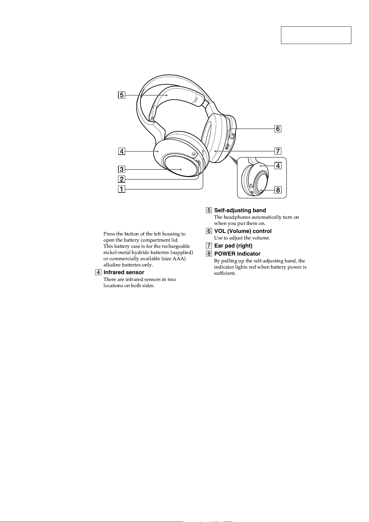
LOCATING THE CONTROLS
SECTION 1
GENERAL
This section is extracted
from instruction manual.
1 Ear pad (left)
2 Battery case button
3 Battery case
Press the button of the left housing to
open the battery compartment lid.
This battery case is for the rechargeable
nickel-metal hydride batteries (supplied)
or commercially available (size AAA)
alkaline batteries only.
4 Infrared sensor
There are infrared sensors in two
locations on both sides.
5 Self-adjusting band
The headphones automatically turn on
when you put them on.
6 VOL (Volume) control
Use to adjust the volume.
7 Ear pad (right)
8 POWER indicator
By pulling up the self-adjusting band, the
indicator lights red when battery power is
sufficient.
3
MDR-IF4000
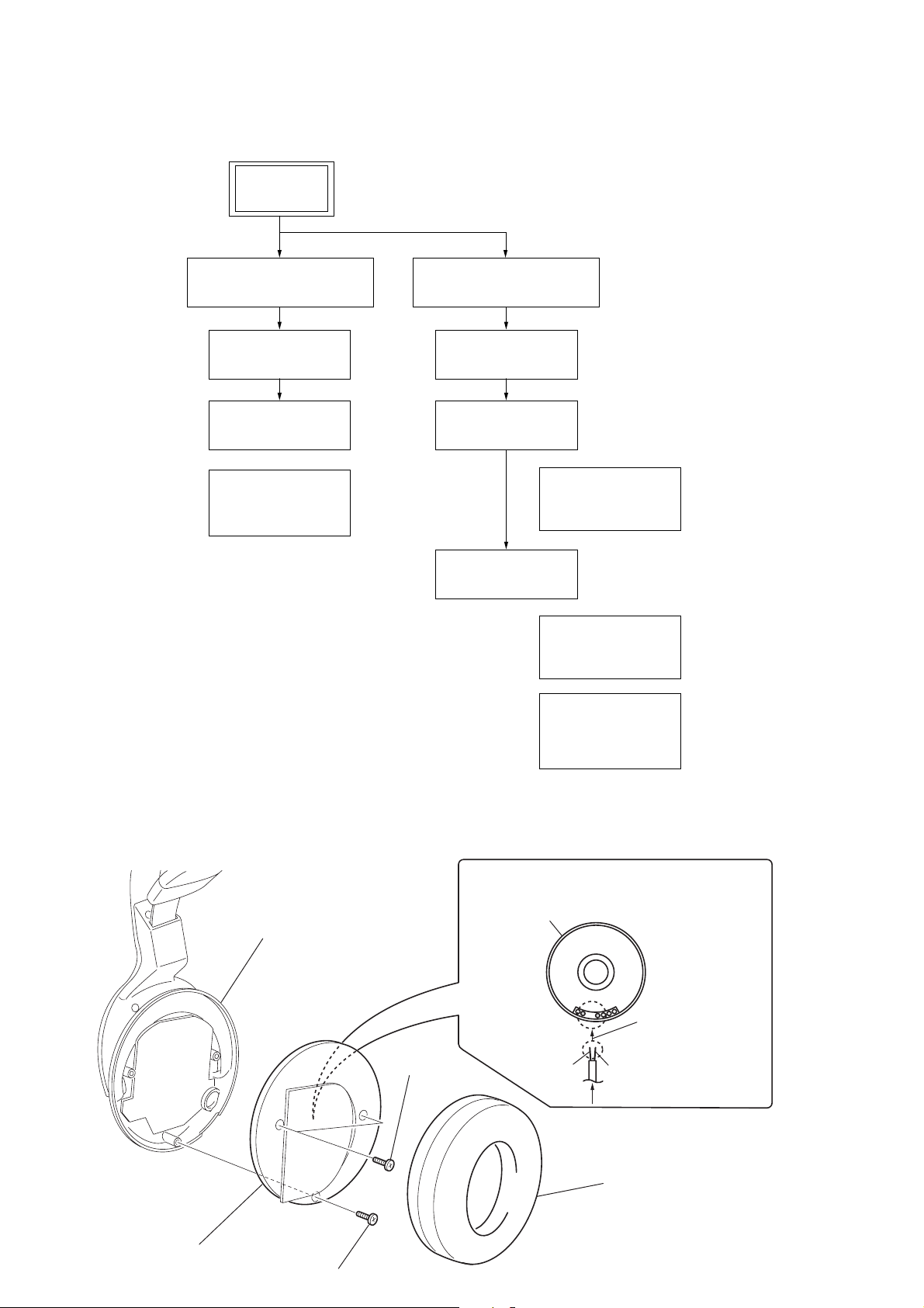
• This set can be disassembled in the order shown below.
2-1. DISASSEMBLY FLOW
SET
SECTION 2
DISASSEMBLY
2-2. FRONT PLATE (R) ASSY
(Page 4)
2-3. RX BOARD
(Page 5)
2-4. HANGER (R)
(Page 5)
2-5. WIRING ON THE
RIGHT SIDE
(Page 6)
Note: Follow the disassembly procedure in the numerical order given.
2-6. FRONT PLATE (L) ASSY
(Page 6)
2-7. BATT BOARD
(Page 7)
2-8. HANGER (L)
(Page 7)
2-9. WIRING ON THE
LEFT SIDE
(Page 8)
2-10.HANGER LID (L)
(Page 8)
2-11.WIRING ON THE
SW BOARD
(Page 9)
2-12.HOW TO HANG
THE TENSDION
SPRING
(Page 9)
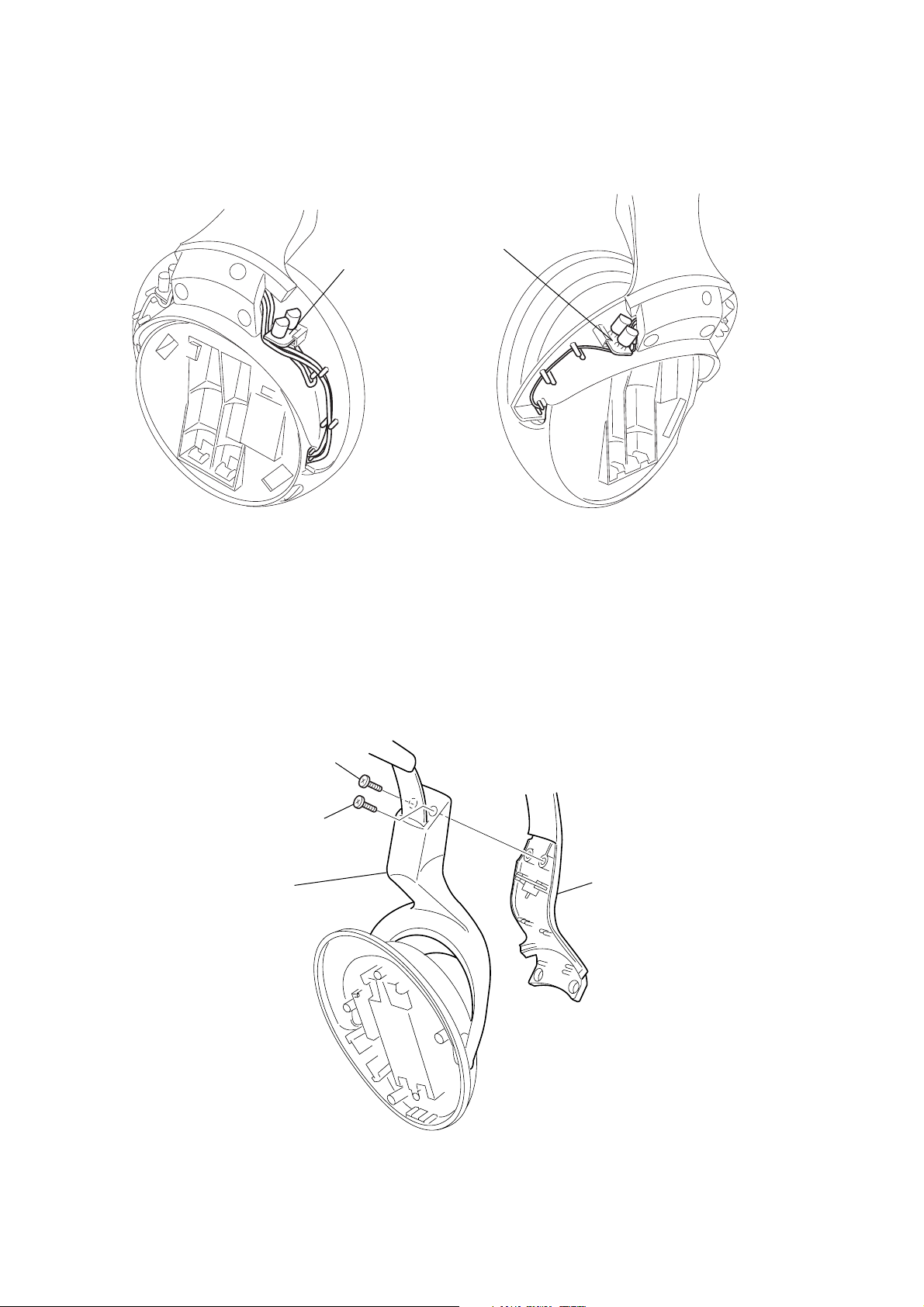
2-2. FRONT PLATE (R) ASSY
housing (R) assy
5
front plate (R) assy
4
3
screw (P 2.6x6)
2
two screws
(P 2.6x6)
4
Removal the solder at 2 places.
Note for installation : Solder the leads at the
places shown below with
attention to their colors.
driver (R-CH) side
Connect a red lead to
the marked one of the
driver terminals.
RED
natural
from RX board
1
ear pad (R)
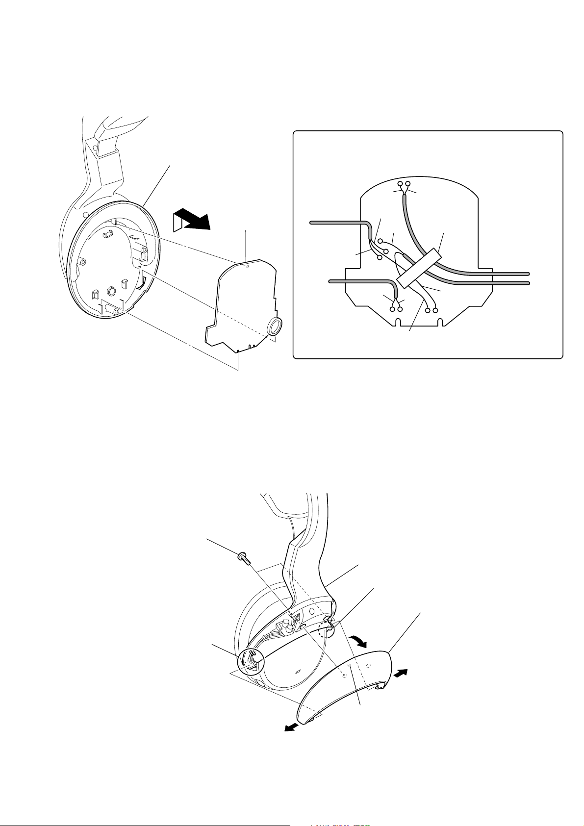
2-3. RX BAORD
)
housing (R) assy
1
Removal the solder at 9 places.
Note for installation : Solder the leads at the
places shown below with
attention to their colors.
MDR-IF4000
2-4. HANGER (R)
2
3
RX board
to BATT board
and driver (L-CH)
RED
to driver
(R-CH)
natural
natural
BLK
GRN
natural
RED
WHT
cushion (B)
GRN
to PD2 board
to BATT board
and driver (L-CH)
1
two screws (P2.6 x 6)
Pay attention to the leads
when assembling.
4
hanger lid (R)
Pay attention to the leads
when assembling.
2
projection
5
3
hanger (R
5

MDR-IF4000
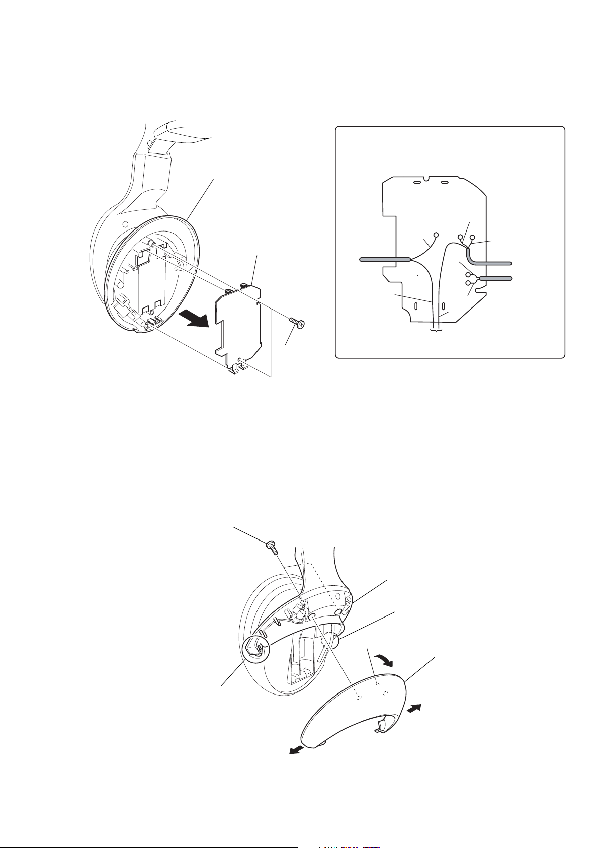
2-5. WIRING ON THE RIGHT SIDE
RD1 board (R-CH front)
RD2 board (R-CH rear)
2-6. FRONT PLATE (L) ASSY
housing (L) assy
2
two screws
(P 2.6x6)
4
Removal the solder at 2 places.
Note for installation : Solder the leads at the
places shown below with
attention to their colors.
driver (R-CH) side
natural
GRN
from RX board
1
ear pad (L)
Connect a green lead to
the marked one of the
driver terminals.
GRN
natural
RED
5
front plate (R) assy
3
screw (P 2.6x6)
6
2-7. BATT BOARD
housing (L) assy
1
Removal the solder at 4 places.
Note for installation : Solder the leads at the
places shown below with
attention to their colors.
natural
MDR-IF4000
2-8. HANGER (L)
3
1
two screws (P2.6 x 6)
4
BATT board
2
(P 2.6x6)
two screws
to RX board
natural
GRN
to driver (L-CH)
RED
GRN
RED
to RX board
to SW board
RED
Pay attention to the leads
when assembling.
4
hanger lid (L)
projection
Pay attention to the leads
when assembling.
2
5
3
hanger (L)
7
MDR-IF4000
2-9. WIRING ON THE LEFT SIDE
RD2 board (L-CH front)
RD1 board (L-CH rear)
2-10. HANGER LID (L)
1
screw (P2.6 x 6)
2
screw (P2.6 x 6)
hanger lid (L)
3
head band
8
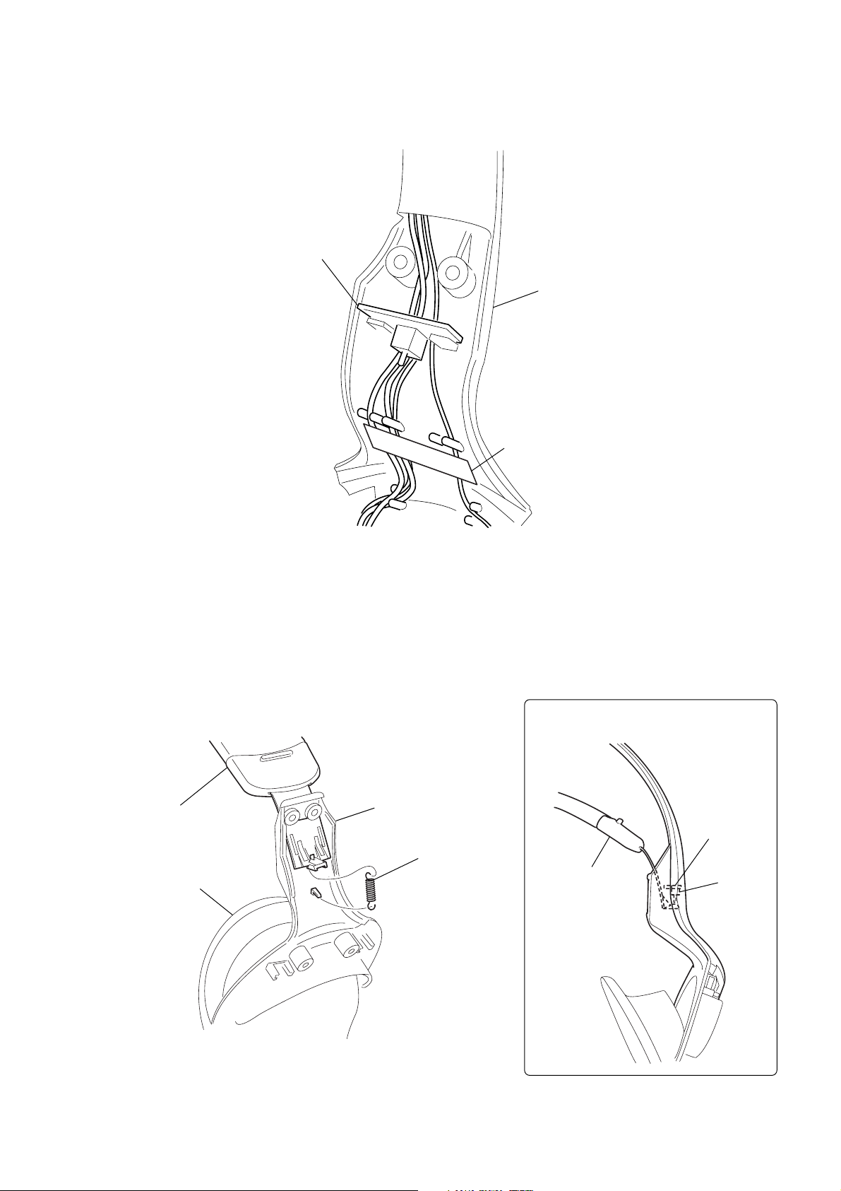
2-11. WIRING ON THE SW BOARD
d
SW board
MDR-IF4000
head ban
2-12. HOW TO HANG THE TENSION SPRING
suspender assy
hanger lid (L)
cushion (B)
Note for installation : Insert the end of the
suspender assy under
the S701 on SW board.
SW board
housing (L) assy
tension spring
suspender assy
S701
9
 Loading...