

Page 1
2-649-139-11(1)
Digital Surround
Headphone
System
Operating Instructions
Mode d’emploi
Manual de instrucciones
US
FR
ES
MDR-DS6000
© 2006 Sony Corporation
Page 2

WARNING
NOTICE FOR THE CUSTOMERS IN THE
U.S.A.
To reduce the risk of fire or
electric shock, do not expose
this apparatus to rain or
moisture.
To avoid electrical shock, do not open
the cabinet. Refer servicing to qualified
personnel only.
For the customers in the USA
Owner’s Record
The model number is located at the
bottom of the processor and the left
inner side of the headband.
The serial number is located at the
bottom of the processor and the inner
side of the battery compartment.
Record these numbers in the spaces
provided below. Refer to them whenever
you call upon your Sony dealer
regarding this product.
Model No. MDR-DS6000
Processor DP-RF6000
Headphones MDR-RF6000
Serial No.
Processor
Headphones
NOTE
The transmitter (Processor) must not be
co-located or operated in conjunction with
any other antenna or transmitter.
The transmitter (Processor) complies with
FCC radiation exposure limits set forth for
uncontrolled equipment and meets the FCC
radio frequency (RF) Exposure Guidelines in
Supplement C to OET65.
The transmitter (Processor) should be
installed and operated with at least 20 cm and
more between the radiator and person’s body
(excluding extremities: hands, wrists, feet and
legs).
US
2
NOTE
This equipment has been tested and found to
comply with the limits for a Class B digital
device, pursuant to Part 15 of the FCC Rules.
These limits are designed to provide
reasonable protection against harmful
interference in a residential installation. This
equipment generates, uses and can radiate
radio frequency energy and, if not installed
and used in accordance with the instructions,
may cause harmful interference to radio
communications. However, there is no
guarantee that interference will not occur in a
particular installation. If this equipment does
cause harmful interference to radio or
television reception, which can be determined
by turning the equipment off and on, the user
is encouraged to try to correct the interference
by one or more of the following measures:
– Reorient or relocate the receiving antenna.
– Increase the separation between the
equipment and receiver.
– Connect the equipment into an outlet on a
circuit different from that to which the
receiver is connected.
– Consult the dealer or an experienced radio/
TV technician for help.
You are cautioned that any changes or
modifications not expressly approved in this
manual could void your authority to operate
this equipment.
For the customers in the Canada
Operation is subject to the following two
conditions: (1) this device may not cause
interference, and (2) this device must accept
any interference, including interference that
may cause undesired operation of the device.
The transmitter (Processor) complies with IC
radiation exposure limits set forth for
uncontrolled equipment and meets RSS-102 of
the IC radio frequency (RF) Exposure rules.
The transmitter (Processor) should be
installed and operated with at least 20 cm and
more between the radiator and person’s body
(excluding extremities: hands, wrists, feet and
legs).
Page 3
For the customers in the USA and Canada
RECYCLING NICKEL METAL
HYDRIDE BATTERIES
Table Of Contents
Main Features .............................. 4
Nickel Metal Hydride
batteries are recyclable.
You can help preserve our
environment by returning
your used rechargeable
batteries to the collection
and recycling location
nearest you.
For more information regarding recycling
of rechargeable batteries, call toll free
1-800-822-8837, or visit http://www.rbrc.org/
Caution: Do not handle damaged or
leaking Nickel Metal Hydride batteries.
Checking the Components and
Accessories .............................. 6
Location and Function of Parts ..
Front Panel of the Processor .............. 7
Rear Panel of the Processor ............... 8
Headphone Part Descriptions ........... 9
Charging the Supplied
Rechargeable Nickel-metal
Hydride Battery ...................... 10
Inserting the supplied rechargeable
nickel-metal hydride battery .......
Charging............................................. 11
Checking the battery power ............ 13
Using the headphones with alkaline
batteries (sold separately) ............
Connecting the Headphone
System .................................... 15
Connecting the processor to
digital components .......................
Connecting the processor to
analog components .......................
Listening to a Connected
Component ............................. 18
7
10
US
14
15
16
Using Additional Headphones ...
23
Replacing the Ear Pads ............ 24
Troubleshooting ........................ 25
Precautions................................ 29
Specifications ............................ 30
3
US
Page 4

Main Features
The MDR-DS6000 is a digital surround headphone system using 2.4 GHz wireless
digital transmission*
1
. You can enjoy multi-channel surround sound with headphones
by simply connecting the digital surround processor to a DVD device or a digital
satellite/TV receiver, etc., with the supplied optical digital connecting cable.
• Compatibility of MDR-DS6000 with a wide variety of audio formats. Compatible
with Dolby Digital*
2
, Dolby Pro Logic II*2, DTS*2 and MPEG-2 AAC*2 formats.
(Can play media marked with “Dolby Digital Surround EX” and “DTS-ES”.)
•Wireless headphones using a digital radio frequency transmission system which
reproduces uncompressed transmission sound, resistant to external noise and
interference.
• Wireless transmission means you can use these headphones anywhere indoors
without worrying about things getting in the way. (Range: Up to approx. 30 m)*
3
• Superior “Virtualphones Technology”*4 creates a surround sound field within the
headphones with realistic presence.
• Built-in audio compression function for easy listening even in the bursting and
whispering sound by compressing the dynamic range.
• Built-in digital through terminal.
Signal to the DIGITAL IN terminal is parallel routed through, for convenient
integration into your existing system with no need to reconfigure your hookup.
• Battery is automatically charged by placing the headphones on the processor.
• Self-adjusting mechanism headband eliminating the need for adjustment.
• Auto Power On/Off function automatically turns on the headphones when you put
them on, and turns them off when they are removed.
• Uses either rechargeable nickel-metal hydride battery (supplied) or commercially
available (size AA) alkaline batteries.
• For reproduction of movie sound quality, headphones use XD long stroke
diaphragms with wide-diameter 40 mm driver units.
US
4
Page 5

*1“SYNIC Intelligent Wireless” is a trademark of Syncomm Technology Corp. to represent
uncompressed digital radio frequency transmission technology. This technology employs a
radio frequency carrier, by which audio signals are transmitted with minimum delay and high
fidelity.
The digital surround processor for this system incorporates the Dolby Digital decoder,
the Dolby Pro Logic II decoder, the DTS decoder and the MPEG-2 AAC decoder.
*2Manufactured under licence from Dolby Laboratories and Digital Theater Systems, Inc.
“Dolby,” “Pro Logic,” the “AAC” logo, and the double-D symbol are trademarks of Dolby
Laboratories.
“DTS” and “DTS Virtual” are trademarks of Digital Theater Systems, Inc.
AAC patent marking
Pat. 5,848,391; 5,291,557; 5,451,954; 5 400 433; 5,222,189; 5,357,594; 5 752 225; 5,394,473;
5,583,962; 5,274,740; 5,633,981; 5 297 236; 4,914,701; 5,235,671; 07/640,550; 5,579,430;
08/678,666; 98/03037; 97/02875; 97/02874; 98/03036; 5,227,788; 5,285,498; 5,481,614;
5,592,584; 5,781,888; 08/039,478; 08/211,547; 5,703,999; 08/557,046; 08/894,844
*3Transmission distance varies depending on conditions of use.
*4“Virtualphones Technology” is a registered trademark of Sony Corporation.
US
5
Page 6
1 Preparation
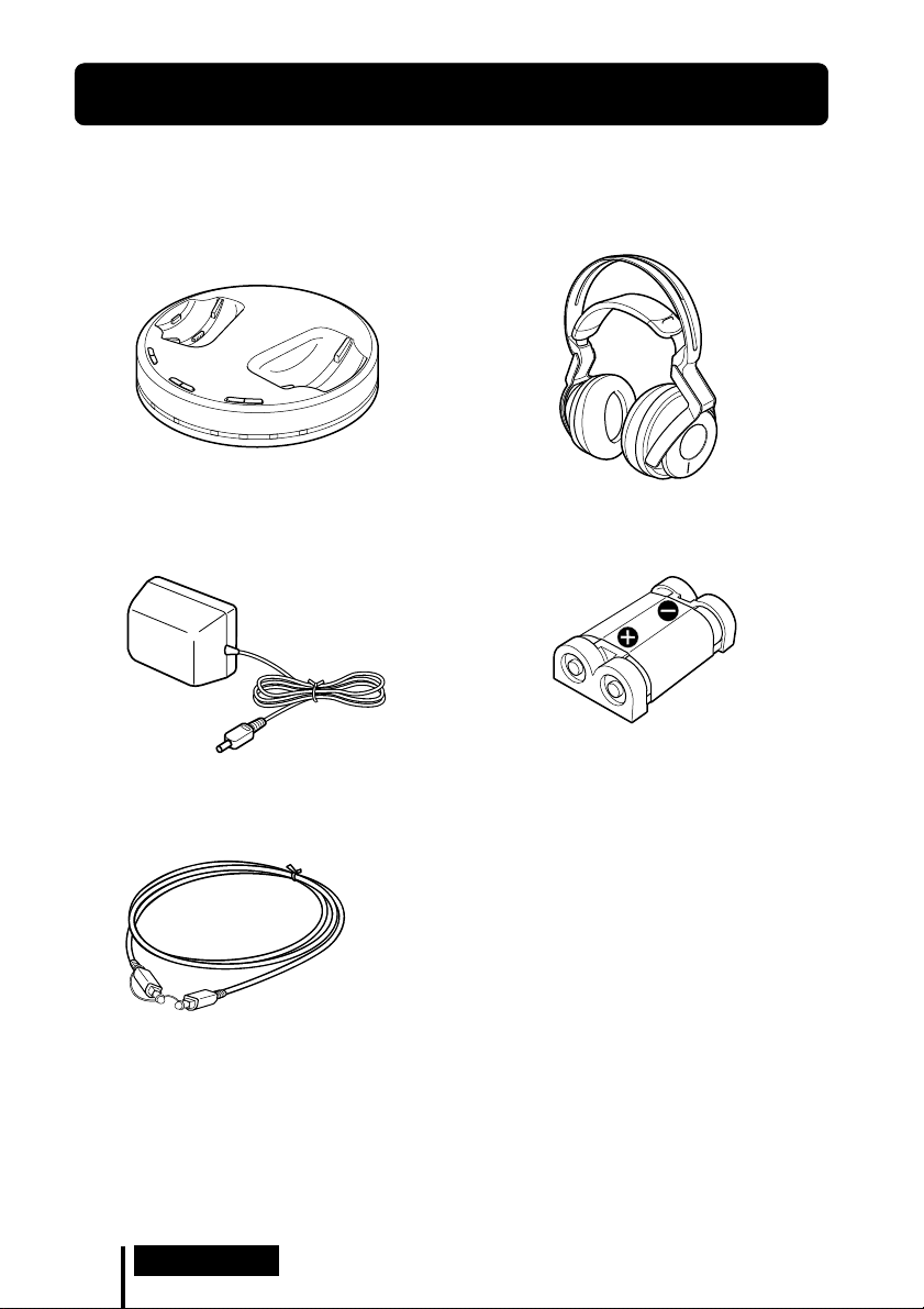
Checking the Components and Accessories
Before setting up the system, check that all of the components are included.
Wireless stereo headphones MDR-RF6000 (1)Processor DP-RF6000 (1)
AC power adaptor (1)
Optical digital connecting cable
(rectangular type y rectangular type) (1)
Rechargeable nickel-metal hydride battery
BP-HP2000 (1)
US
6
Preparation
Page 7

Location and Function of Parts
Front Panel of the Processor
1
2
C
O
O
M
F
P
F
R
E
S
S
I
O
N
O
N
I
N
T
P
C
U
E
L
T
E
S
A
L
N
A
A
T
I
L
G
O
I
G
D
A
M
T
E
C
N
E
I
F
C
F
E
F
F
O
C
I
S
U
M
1 Contact pin
2 Charging lever
3 COMPRESSION switch
(See page 20
for details.)
4 INPUT SELECT switch
Slide to select the input source
(DIGITAL/ANALOG).
5 EFFECT switch
(See page 19
Slide to select the sound field (MUSIC/
OFF/CINEMA).
for details.)
3
CHG RF DTS
6
7 8
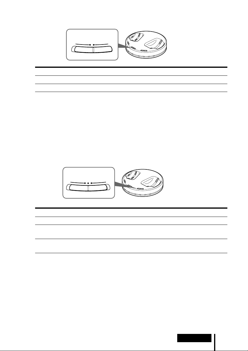
6 CHG indicator
Lights red while charging.
7 RF indicator
Lights blue while emitting RF signals.
8 DECODE MODE indicators
(See page 20
45
DOLBY DIGITAL DOLBY PRO LOGIC MPEG-2 AAC
for details.)
Preparation
US
7
Page 8
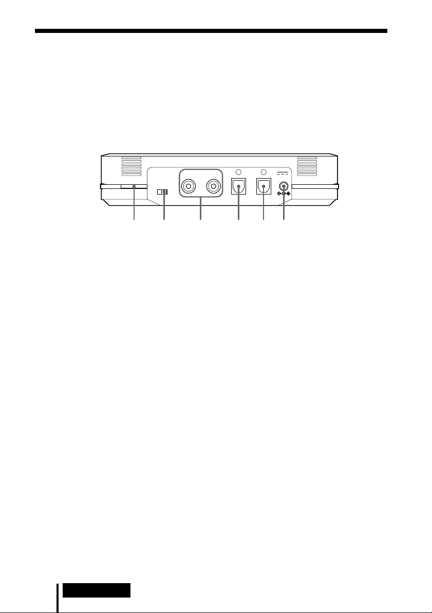
Rear Panel of the Processor
LLINE IN
TUNE/ID SET
0dB -8dB
12 3 456
R
ATT
DIGITAL IN DIGITAL OUT
DC IN 9V
(THROUGH)
1 TUNE/ID SET button
(See pages 21 and 23 for details.)
Use this button when reception
deteriorates, or when using additional
headphones.
2 ATT (attenuator) switch
Set this switch to “0 dB” if the volume is
too low for analog input. Normally, this
switch should be set to “–8 dB.”
3 LINE IN jacks
(See page 16 for details.)
Connect the audio output jacks on an
audio or video component (sold
separately), such as a video cassette
player or TV, to these jacks.
US
8
Preparation
4 DIGITAL IN jack
(See page 15 for details.)
Connect a DVD device, digital satellite/
TV receiver, or other digital component
(sold separately) to this jack.
5 DIGITAL OUT jack
(See page 15 for details.)
Connected components' digital signal
integrity retained when installed.
6 DC IN 9V jack
Connect the supplied AC power adaptor
to this jack. (Be sure to use the supplied
AC power adaptor. Using products with a
different plug polarity or other
characteristics can cause a malfunction.)
Page 9
Headphone Part Descriptions
T
U
N
E
/ I
D
S
E
T
T
U
N
E
/ I
V
O
L
D
S
E
T
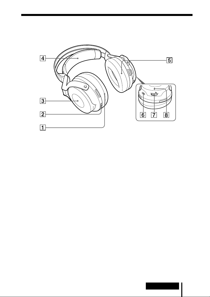
1 Ear pad (left)
2 Contact point
3 Battery case
This battery case is for the rechargeable
nickel-metal hydride battery (supplied) or
commercially available (size AA) alkaline
batteries only.
4 Self-adjusting band
The headphones automatically turn on
when you put them on.
5 Ear pad (right)
6 TUNE/ID SET button
(See pages 21 and 23 for details.)
Use this button when reception
deteriorates, or when using additional
headphones.
7 VOL (Volume) control
Use to adjust the volume.
8 POWER indicator
By pulling up the self-adjusting band, the
indicator lights blue when battery power
remains.
Preparation
US
9
Page 10
Charging the Supplied Rechargeable
Nickel-metal Hydride Battery
The supplied rechargeable nickel-metal hydride battery is not charged from the first
time you use it. Be sure to charge it before use.
To charge the headphones, place them on the processor.
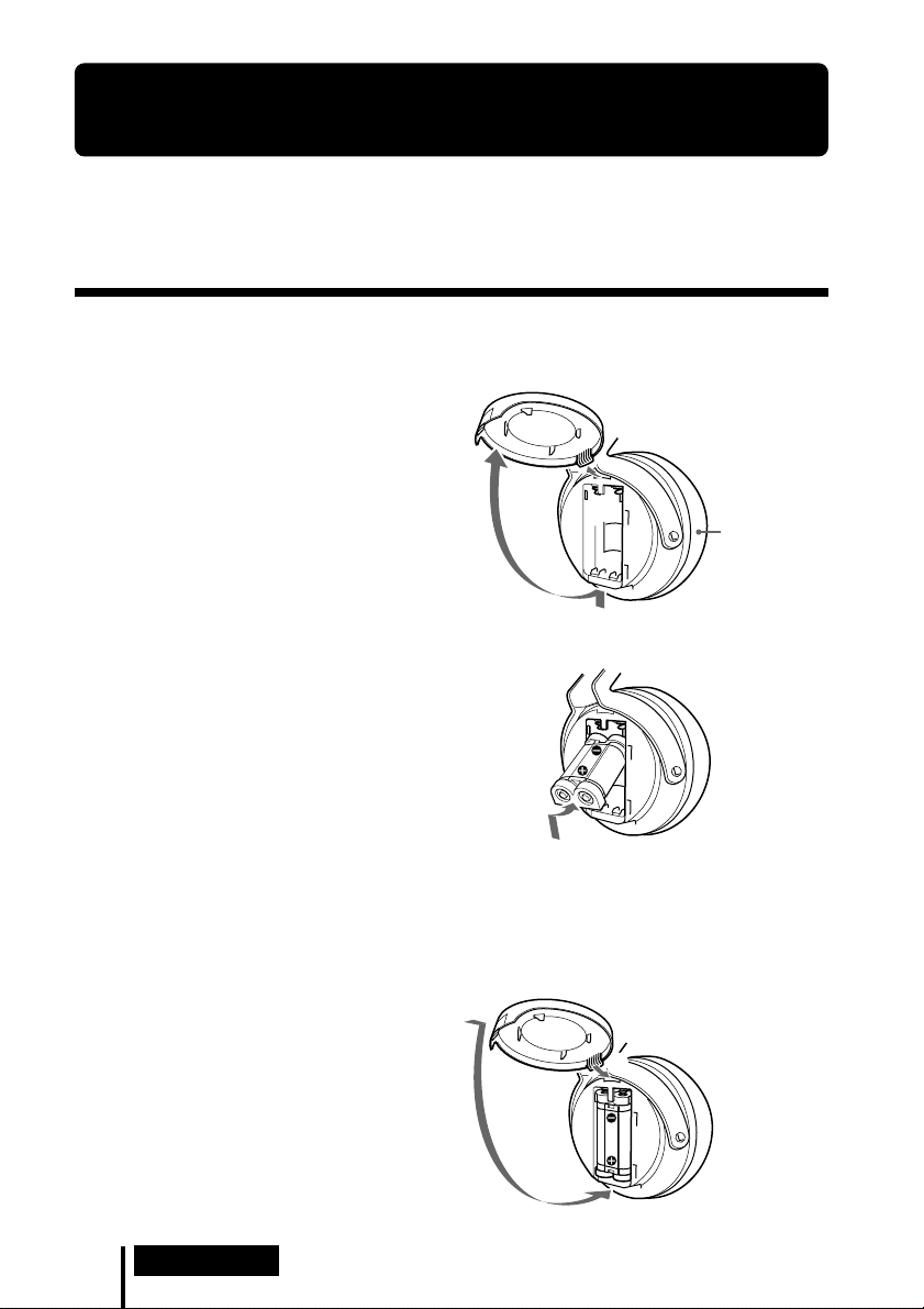
Inserting the supplied rechargeable nickelmetal hydride battery
1 Open the battery compartment lid
of the left housing.
The battery compartment lid comes
off.
Left housing
2 Insert the supplied rechargeable nickel-
metal hydride battery into the battery
compartment, matching the 3 terminal on
the battery to the 3 mark in the
compartment.
Do not attempt to charge any other kind of
battery with this unit.
Note
The battery compartment has a tab on the # side which holds the battery in place. Insert the
# terminal first when installing the battery.
3 Close the battery compartment lid.
US
10
Preparation
2
1
Page 11

Charging
1 If your AC power adaptor is equipped with an on/off switch, set it to ON.
The power is supplied to the processor.
On/off switch
2 Connect the supplied AC power adaptor to the processor.
To an AC outlet
Processor
To DC IN 9V jack
Notes
• Be sure to use the supplied AC power adaptor. Using AC adaptors with different plug
polarity or other characteristics can cause product failure.
Unified polarity plug
• Be sure to always use the supplied AC power adaptor. Even AC power adaptors having
the same voltage and plug polarity can damage this product due to the current capacity
or other factors.
AC power
adaptor
(supplied)
(Continued)
Preparation
11
US
Page 12
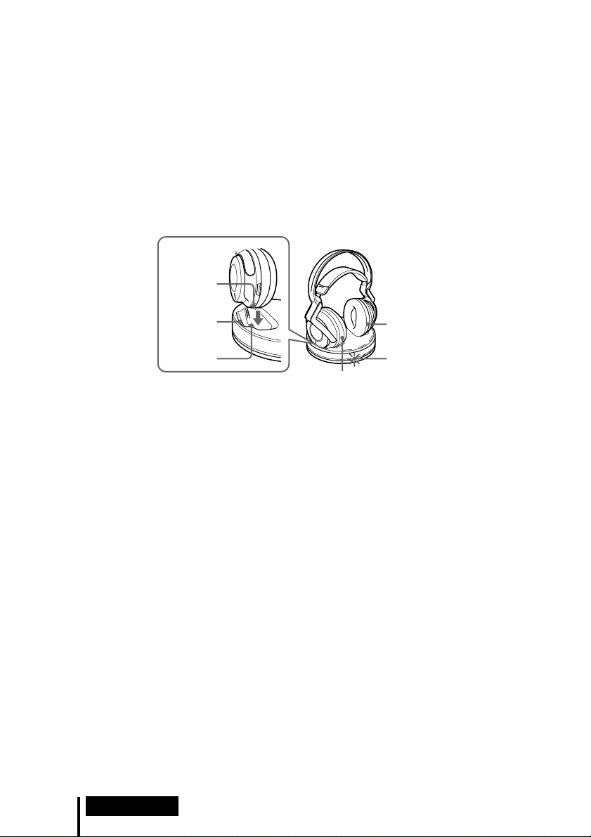
3 Rest the headphones on the processor so that the headphones’ contact point
meets the processor’s contact pin, and make sure that the CHG indicator
lights up.
It takes approx. 3 hours to fully charge the battery (the CHG indicator goes off
when charging is complete).
When placing the headphones on the processor, be sure to hold them with both
hands so that the right and left housings are horizontal, and place the
headphones vertically on the processor. The charging lever is pushed down and
the contact pin comes up. When the processor’s contact pin meets the
headphones’ contact point, the CHG indicator lights up.
Contact
point
Charging
lever
Contact pin CHG
Left housing
Right
housing
indicator
If the CHG indicator is not lit
• Be sure to close the battery compartment lid. The battery charge function is not
activated when the lid is not fully closed.
• Check if the right and left headphones are rested on the processor correctly.
• The indicator will not light up if the headphones’ contact point does not meet the
processor’s contact pin. In this case, remove the headphones and place them on the
processor again so that the indicator lights up.
• Make sure that the supplied rechargeable nickel-metal hydride battery is installed
in the battery compartment. Dry batteries cannot be charged.
• If the rechargeable battery is damaged or the 3 and # of the battery do not match
those in the battery compartment correctly, the CHG indicator blinks.
12
US
Preparation
Page 13
To recharge the headphone battery after use
Place the headphones on the processor after use. The CHG indicator lights up, and the
RF indicator goes off, and then charging starts.
Since the built-in timer recognizes when charging is complete (approx. 3 hours), there
is no need to remove the headphones from the processor after charging has
completed.
Notes
• The processor automatically turns off while charging the battery.
• This system is designed to charge only the supplied rechargeable battery, type BP-HP2000, for
safety. Note that other types of rechargeable batteries cannot be charged with this system.
• If dry batteries are installed, they cannot be charged.
• Do not attempt to use the supplied BP-HP2000 rechargeable battery with other components. It
is for use with this system only.
• Charge in an environmental temperature of between 0˚C and 40˚C (between 32˚F and 104˚F).
Otherwise, the battery may not be fully charged.
• Do not touch the contact pin of the processor. If a contact pin becomes dirty, charging may not
be possible.
• Charging may not be completed if the processor’s contact pin and headphones’ contact point
are dusty. Wipe them with a cotton bud, etc.
Charging and usage time
Approx. charging time Approx. usage time*
2
3 hours*
*1 at 1 kHz, 1 mW + 1 mW output
*2 hours required to fully charge an empty battery
*3 Time may vary, depending on the temperature or conditions of use.
7 hours*
3
1
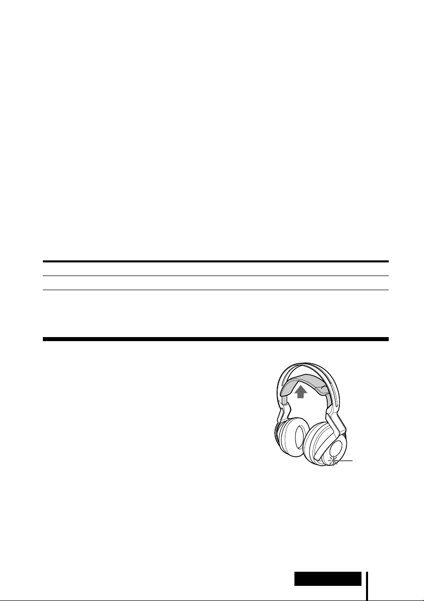
Checking the battery power
Pull up the self-adjusting band and check the POWER
indicator located on the right housing. The battery is
still usable when the indicator lights blue.
Charge the rechargeable battery or install new alkaline
batteries if the POWER indicator does not light up.
POWER
indicator
Note
The rechargeable nickel-metal hydride battery should be replaced with a new one when it lasts
only half the expected time, after a full charge has been performed. The rechargeable battery,
type BP-HP2000, is not commercially available. You can order the battery from the store where
you purchased this system, or at your nearest Sony dealer.
Preparation
13
US
Page 14

Using the headphones with alkaline batteries
(sold separately)
Commercially available (size AA) alkaline batteries can also be used to power the
headphones. Install the batteries in the same manner as described in “Inserting the
supplied rechargeable nickel-metal hydride battery” (page 10).
When dry batteries are installed, the battery charge function is not activated.
Battery life
Battery Approx. hours*
Sony alkaline batteries 5 hours*
LR6(SG)
*1 at 1 kHz, 1 mW + 1 mW output
*2 Time may vary, depending on the temperature or conditions of use.
Notes on batteries
• Do not charge a dry battery.
• Do not carry a battery together with coins or metallic objects. Heat can be generated by the
battery if its positive and negative terminals are accidentally shorted.
• When you are not going to use the unit for a long time, remove the batteries to avoid damage
from battery leakage or corrosion.
2
1
14
US
Preparation
Page 15
1 Connection
Connecting the Headphone System
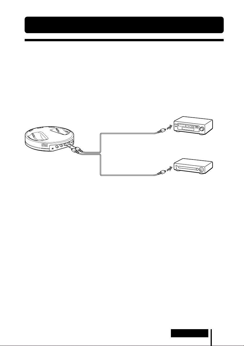
Connecting the processor to digital
components
Use the supplied optical digital connecting cable to connect the optical digital output
1
on a DVD device, digital satellite/TV receiver, or other digital component*2 to
jack*
the DIGITAL IN jack (black) of the processor.
The connected AV component may need to be set up for optical digital output. Read
their operating instructions of the connected device.
When connecting the processor to an AV amplifier, etc., connect the DIGITAL OUT
jack (Red) and external optical digital input jack using the optical digital connecting
cable (sold separately).
Processor
To DIGITAL
OUT jack
(Red)
To DIGITAL IN
jack (Black)
Optical digital connecting
cable (sold separately)
To optical digital
input jack
To optical digital
output jack
Equipment with optical
digital input terminal such
as an AV amplifier
Optical digital connecting cable (supplied)
Match the orientation of the plug with the
jack, and then insert until the plug fits into
place.
Notes
• The optical digital connecting cable is an extremely high-precision device and is sensitive to
jolts and external pressure. Therefore, be careful when inserting and removing the cable plug.
• The digital input for the processor does not support sampling frequencies of 96 kHz. Set the
digital output setting of the DVD device to 48 kHz when using this system. Noise may be
heard when a 96 kHz digital signal is input.
*1If the connected equipment supports PCM output only, all surround sound effects will be
processed by DOLBY PRO LOGIC II.
*2Connection to the optical digital output jack on your personal computer is not guaranteed to
work with this system.
DTS
•A DTS-compatible DVD device is required for playback of DVDs recorded in DTS audio. (For
more details, see the instruction manual of your DVD device.)
• When playing CDs recorded in DTS format, noise may occur when fast forwarding or
rewinding. This is not a malfunction.
• If the DTS digital output is set to “OFF” on the DVD device, no sound may be heard even if the
DTS output is selected in the DVD menu.
• No sound may be heard when a DVD device and this unit is analog-connected. In this case,
use a digital connection.
DVD device, digital satellite/TV
receiver, or other digital
component having an optical
digital output jack
(Continued)
Connection
15
US
Page 16
Connecting cables (sold separately)
Use the optical digital connecting cable POC-15AB (mini-plug y rectangular plug) when
connecting the optical digital output mini-jack on portable DVD players, portable CD players, or
other digital components to the DIGITAL IN jack.
Notes on optical digital connecting cable
• Do not drop objects on the optical digital connecting
cable or expose the cable to shock.
• Grasp the plug to connect or disconnect the cable.
• Be sure that the ends of the optical digital connecting
cable are kept clean. Dust at the ends of the cable can
degrade performance.
•When storing the system, attach the cap to the end of the plug
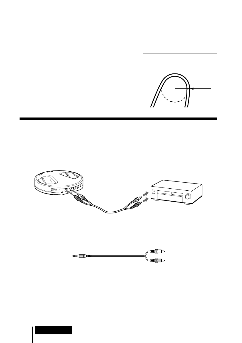
The bend radius of the optical
digital connecting cable should be
no less than 25 mm
(1
inch).
25 mm
(1
inch
)
and be careful not to fold or bend the optical digital
connecting cable with a bend radius less than 25 mm (1 inch).
Connecting the processor to analog
components
Use an audio cord (sold separately) to connect the audio output jacks on a VCR, TV,
or other component to the LINE IN (L/R) jacks on the processor.
Processor
Audio right (R, red)
To LINE IN jacks
Audio left
(L, white)
Audio cord
(sold separately)
To audio output jacks
Audio left
(white)
Audio right (red)
VCR, TV, or other
component
Connecting cables (sold separately)
Use the connecting cable (stereo mini-plug y pin plug × 2) when connecting a stereo mini-jack
(line out jack or headphone jack) to the LINE IN jacks.
In this case, set the volume on the player at a medium level. Noise can occur if the volume on the
player is set too low.
US
16
Connection
Page 17
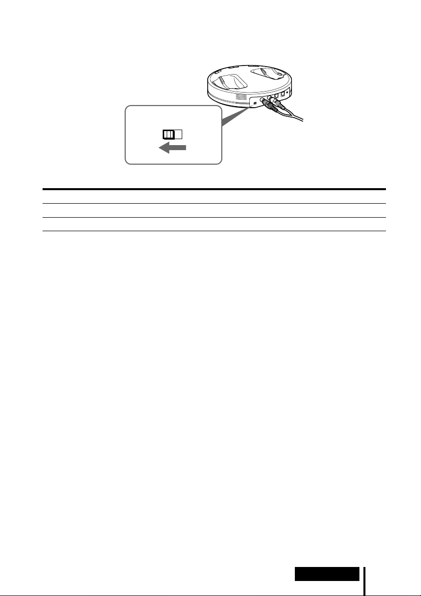
Setting the input level
If the volume is low using the analog input, set the ATT (attenuator) switch to “0 dB.”
AT T
0dB -8dB
Setting Connected components
0 dB TV, portable components, and other components with a low output level
–8 dB Other components (initial settings)
Notes
• Be sure to lower the volume before setting the ATT switch.
• If audio input to the LINE IN jacks is distorted (sometimes, noise can be heard at the same
time), set the ATT switch to “–8 dB.”
Connection
17
US
Page 18
1 Operation
Listening to a Connected Component
Before starting, be sure to read “Connecting the
Headphone System” (pages 15 to 17) and make the proper
connections.
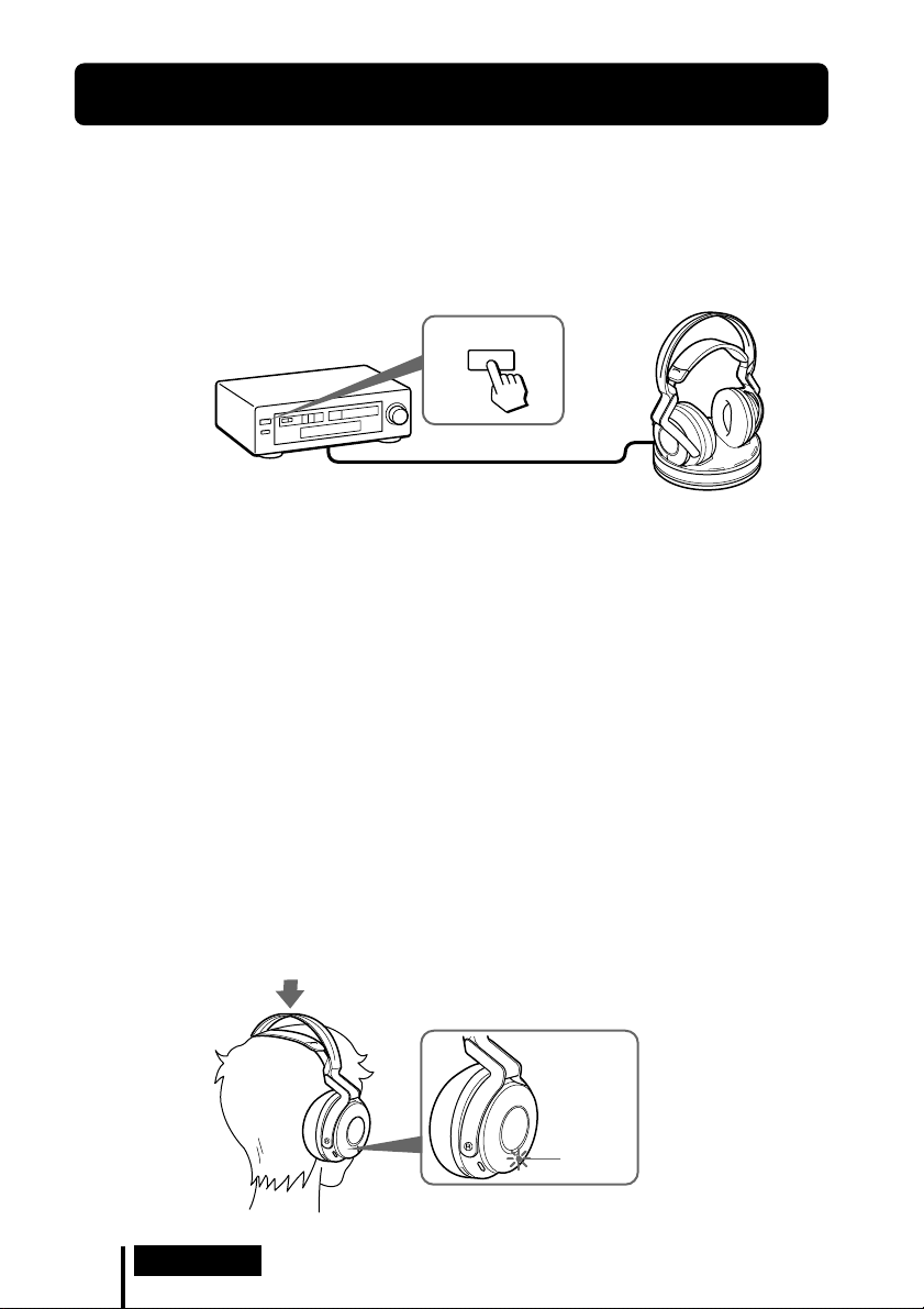
1 Turn on the component connected to the processor.
DVD device, digital satellite/TV
receiver, or other audio or video
component
2 Remove the headphones from the processor.
The processor turns on automatically and the RF indicator blinks for about 5
seconds. The processor automatically detects the optimum frequency for
transmission according to your room conditions. The RF indicator lights up when
emission from the processor starts. Then the DECODE MODE indicator lights up,
depending on the audio signal input from the connected audio or video
component and the setting of the EFFECT switch.
POWER
Signal transmission system
This unit employs a proprietary transmission system using 2.4 GHz frequency.
You can enjoy non-compressed sound with this wireless system.
3 Put on the headphones.
The POWER indicator lights blue, and the headphones automatically turn on.
Be sure to match the right and left side of the headphones with your ears and
wear the headphones at the correct angle so that the Auto Power On/Off function
works correctly. Sound is heard from the headphones about 3 seconds after you
put on the headphones.
POWER
indicator
US
18
Operation
Page 19
4 Slide the INPUT SELECT switch to select the component you want to listen to.
I
N
P
U
A
N
A
L
O
T
C
E
L
T
E
S
L
A
T
I
G
I
G
D
Position of switch Selected sound source
DIGITAL Sound of the component connected to DIGITAL IN jack.
ANALOG Sound of the component connected to LINE IN jacks.
Note
To listen to dual audio (MAIN/SUB) sound sources, connect to the LINE IN jacks, and then
select the sound source you want to listen to on the player, TV, or other component.
5 Start playback of the component selected in step 4.
6 Slide the switch to select the desired sound field, EFFECT or COMPRESSION.
EFFECT switch
T
E
C
F
F
M
E
U
S
I
C
O
F
A
M
E
N
I
C
F
Position of switch Sound field and suitable sound source
OFF Normal playback of the headphones.
CINEMA Produces the kind of surround sound that is found in a typical movie
MUSIC Produces the kind of sound field that would be found in a listening
theater. Suitable for movie sound sources.
room with good acoustics. Suitable for music sources.
Note
The volume of the headphones may vary, depending on the input signal and the setting of
the EFFECT switch.
(Continued)
Operation
19
US
Page 20
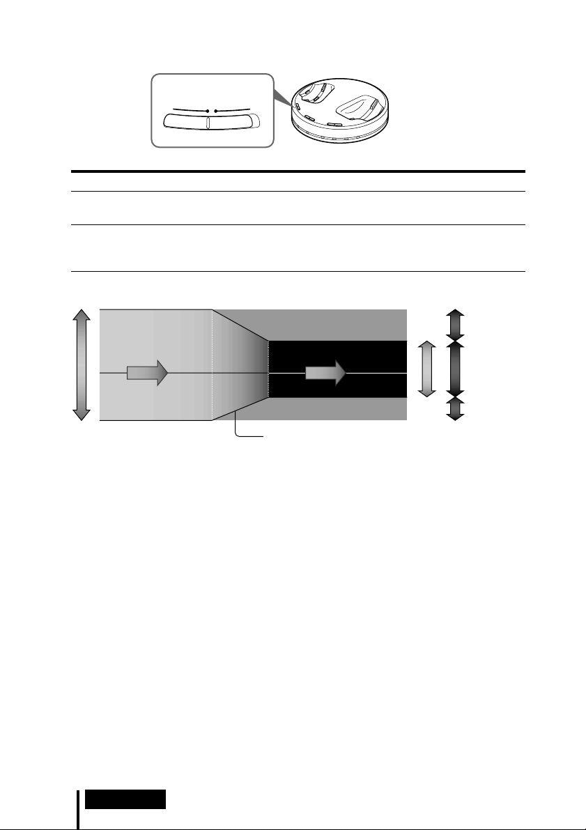
COMPRESSION Switch
C
O
M
O
F
F
N
O
I
P
S
R
S
E
N
O
Position of switch Playback Effect
OFF When the EFFECT switch is selected, the sound mode changes to the
selected effect.
ON This function maintains the overall level of program material:
explosive sounds are attenuated while lower level sounds (dialog,
etc.) are enhanced.
Illustration of the compression process
explosion
dynamic range
dialogue
whisper, background noise
input signal
compression
output signal
Dynamic range compression
by built-in DSP processor
explosion
dialogue
whisper, background noise
dynamic range
standard
Startling
level
Easy to hear
level
Difficult to
hear level
DECODE MODE indicators
The processor automatically identifies the format of the input audio signal and the
corresponding indicator lights up. Switch the audio between Dolby Digital, DTS, MPEG-2
AAC, etc., on the connected equipment (DVD device, digital satellite/TV receiver, etc.).
• DOLBY DIGITAL: Input signal recorded in the DOLBY DIGITAL format.
• DOLBY PRO LOGIC II: Analog input signal, digital input PCM signal, or Dolby Digital
2-channel signal processed by DOLBY PRO LOGIC II.
(If the sound field is set to ”OFF,” it is not processed by DOLBY PRO LOGIC II.)
• DTS: Input signal recorded in the DTS format.
• MPEG-2 AAC: Input signal recorded in the MPEG-2 AAC format.
Note
If the equipment connected to the DIGITAL IN jack is not playing back (fast forwarding,
rewinding, etc.), the DECODE MODE indicators may not light up correctly.
US
20
Operation
Page 21
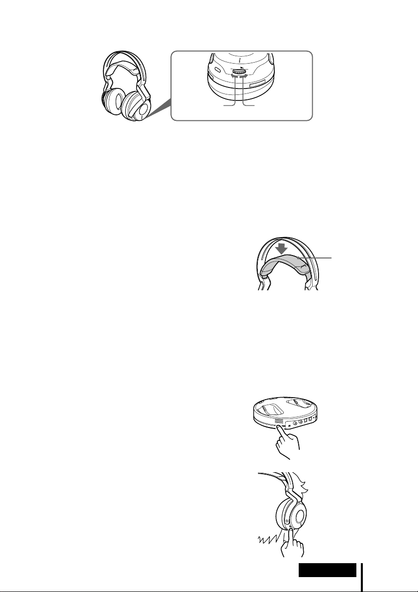
7 Adjust the volume.
V
O
L
Raise the
volume
Notes
• When watching films, be careful not to raise the volume too high in quiet scenes. You
may hurt your ears when a loud scene is played.
• You may hear some noise when you disconnect the AC power adaptor from the
processor before removing the headphones.
Lower the
volume
Transition time between modes
When sliding switches on the processor to change to new modes, the transition time
between modes may vary. This is due to differences in system control between
modes.
The headphones automatically turn off when
they are removed
— Auto Power On/Off function
Self-adjusting
band
Do not pull up the self-adjusting band when not
in use, as this will consume the battery power.
If a beep sound is heard from the headphones
A repeated beep sound is heard if reception conditions deteriorate when the
headphones are outside the signal transmission area, or another wireless apparatus
using 2.4 GHz frequency or microwave oven causes interference. If the beep sound
does not stop after moving closer to the processor, let the processor detect the
optimum frequency for transmission again following the procedure below.
1 Press TUNE/ID SET on the processor once.
The RF indicator blinks and the processor
detects the optimum frequency automatically.
After detection is completed, the RF indicator
lights up and emission starts.
2 Press TUNE/ID SET on the headphones once.
The headphones detect the frequency of the
processor automatically. The beep sound stops
when the headphones start receiving signals.
(Continued)
Operation
21
US
Page 22

RF signal transmission area
The approximate RF signal transmission area from the processor is up to 30 m.
The processor detects the optimum frequency automatically when the headphones
are removed from the processor. The sound may be interrupted if the headphones are
out of RF signal transmission area or reception conditions deteriorate. In this case,
move closer to the processor or press TUNE/ID SET on the processor and
headphones to have them detect the optimum frequency again. See “If a beep sound
is heard from the headphones” (page 21) on how to detect the optimum frequency.
Notes
• Because this system transmits signals at 2.4 GHz, sound may be interrupted if interference
occurs. This is due to radio frequency characteristics, and is not a malfunction.
• Any noise you hear through the headphones may vary depending on the processor position
and room conditions. It is recommended that you place the processor in a location that
produces the clearest sound.
• Sound may be interrupted if the processor is used with other wireless apparatus using 2.4 GHz
frequency, or a microwave oven.
If an audio signal is not input for 5 minutes
RF signal transmission from the processor automatically stops when an audio signal
is not input for 5 minutes. The RF signals are automatically transmitted when an
audio signal is input again. RF signal transmission may stop when an extremely low
sound is input for about 5 minutes. If this happens, raise the volume of the connected
audio or video component and lower the volume of the headphones. If signal noise is
output from a component connected to the LINE IN jacks, RF signal transmission may
not stop.
Tip
If RF signal transmission from the processor stops when an audio signal is not input for 5
minutes, the RF signals are automatically transmitted when an audio signal is input again.
The RF indicator blinks and the processor detects the optimum frequency for transmission. If the
transmission frequency changes after the RF indicator lights up and no sound is heard, press
TUNE/ID SET on the headphones once and tune to the new frequency.
Notes
• The headphones should be used within the RF signal transmission area (see “RF signal
transmission area”).
• The surround sound effect may not be obtained from sound sources that do not incorporate
video, such as music CDs.
• This system simulates the average HRTF* common to most people. However, the effect can
differ from person to person since the HRTF can vary between individuals.
* Head Related Transfer Function
US
22
Operation
Page 23
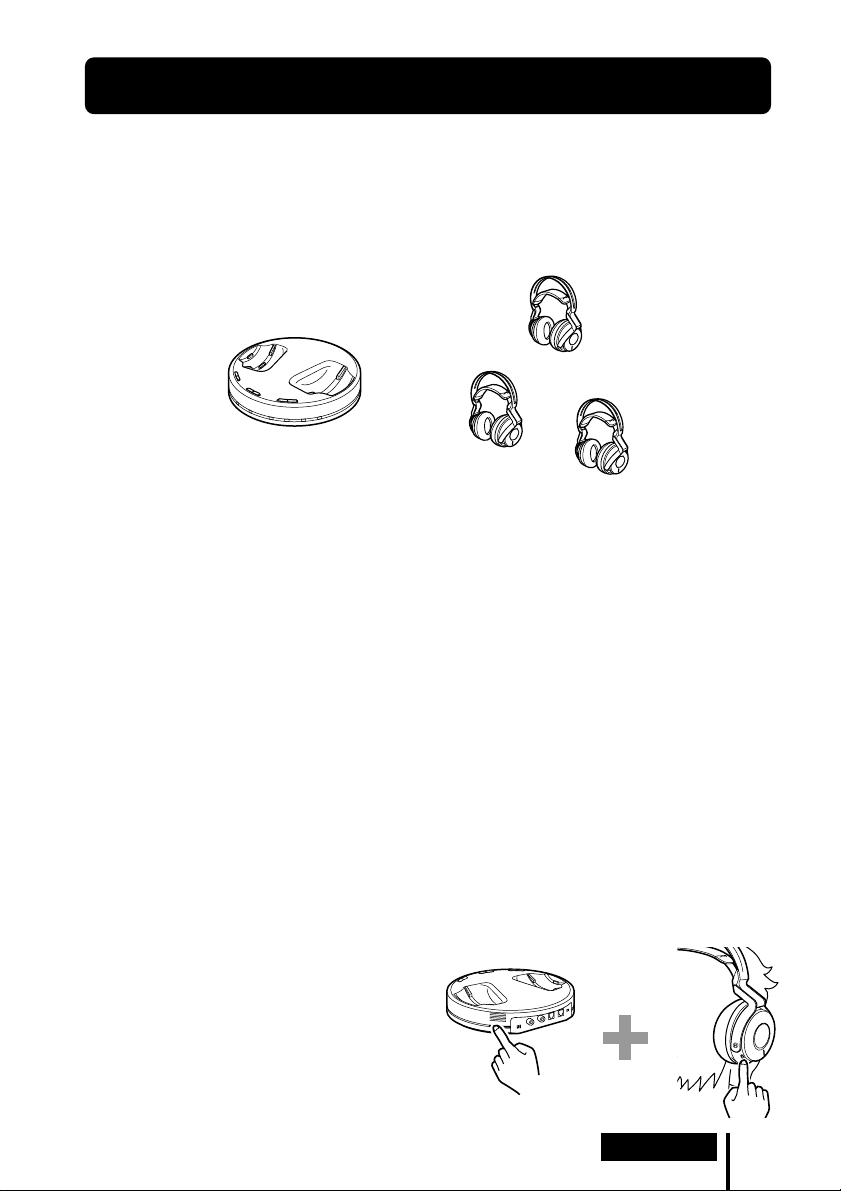
Using Additional Headphones
In this system, by using additional MDR-RF6000 wireless headphones (sold
separately), more than one person can enjoy the surround sound experience
wirelessly at the same time.
Charge additional headphones with the processor of this system.
* There is no limit to the number of headphones that can be used within the RF signal
transmission area.
Processor
Notes
• The processor turns off automatically while charging. Remove these headphones from the
processor when using other headphones.
• This unit is not compatible with headphones other than MDR-RF6000, since this unit employs
a proprietary 2.4 GHz wireless digital transmission system.
When using additional headphones
Each processor has its own ID number. When using additional MDR-RF6000 wireless
headphones (sold separately), be sure to set the processor’s ID to that of the
headphones, otherwise the headphones will not work.
MDR-RF6000
(sold separately)
1 Remove the headphones from the processor.
The processor turns on automatically.
2 Put on the headphones.
The headphones automatically turn on.
Note
Charge the battery of additional headphones before setting their IDs, or use commercially
available (size AA) alkaline batteries.
3 Press and hold TUNE/ID SET on the processor and that on the headphones at
the same time for more than 3 seconds.
A repeated beep sound is heard from the
headphones and ID setting starts. When
the sound changes to a continuous beep
sound, the ID number is set for the
headphones.
Operation
23
US
Page 24
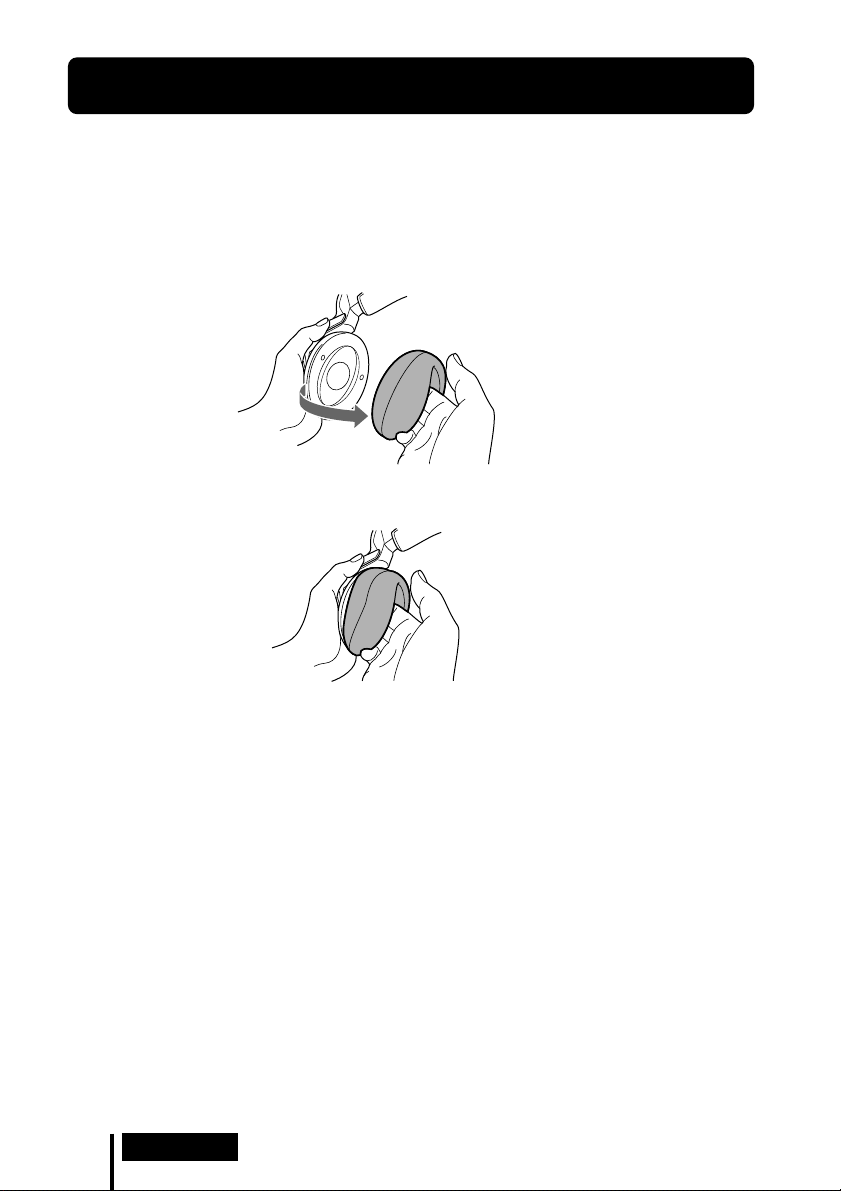
Replacing the Ear Pads
The ear pads are replaceable. If the ear pads become dirty or worn out, replace them
as illustrated below. The ear pads are not commercially available. You can order
replacements from the store where you purchased this system, or at your nearest
Sony dealer.
1 Remove the old ear pad by pulling it off.
2 Place the new ear pad around the housing.
24
US
Operation
Page 25

1 Additional Information
Troubleshooting
If you run into any problems using this headphone system, use the following
checklist. Should any problem persist, consult your nearest Sony dealer.
Symptom Cause and remedy
No sound
, Check the connection between the processor and the AV component.
, Check that the signal is not being input to the digital out jack by mistake when
digital input is selected.
, Check that the connected AV component's optical digital output is set to "ON"
when selecting digital input.
, Turn on the AV component connected to the processor, and start the playback.
, Check that the INPUT SELECT switch on the processor is set to the
component you want to listen to.
, If you connect the processor to an AV component using the headphone jack,
raise the volume level on the connected AV component.
, Make sure you are wearing the headphones correctly.
, Raise the headphone volume.
, The headphones’ POWER indicator goes off.
• Charge the rechargeable battery if it is weak, or replace alkaline batteries
with new ones. If the POWER indicator is still off after charging the battery,
take the headphones to a Sony dealer.
, You are trying to play a DTS audio track on a DVD device that does not
support DTS.
• Either use a DVD device that supports DTS, or select a Dolby Digital or
PCM audio track.
, You are playing back a DVD disc recorded in DTS when DTS digital output
setting for the DVD device (including game machines) is “OFF.”
• See the instruction manual of your DVD device, and change the DTS digital
output setting to “ON.”
, You are playing back a DVD disc recorded in DTS when the DVD device
(including game machines) and the processor are analog-connected.
• Use the digital connection. (Analog sound may not be output from the DVD
device.)
, The processor’s ID is not set for the additional headphones.
, Additional headphones are being charged.
• Remove additional headphones from the processor.
(Continued)
Additional Information
25
US
Page 26

Symptom Cause and remedy
Distorted or
intermittent sound
(sometimes with
noise)
Low sound
Loud background
noise
The sound cuts off
The surround
sound effect is
not obtained
The DOLBY
DIGITAL indicator
does not turn on
, Charge the rechargeable battery if it is weak, or replace alkaline batteries with
new ones. If the POWER indicator is still off after charging the battery, take
the headphones to a Sony dealer.
, Check if there is any wireless apparatus using 2.4 GHz frequency, or a
microwave oven in the vicinity.
, Change the position of the processor.
, When analog input is selected, change the ATT switch on the processor to
"–8 dB."
, If you connect the processor to an AV component using the headphone jack,
lower the volume level on the connected AV component.
, When using DTS audio sources, set the EFFECT switch on the processor to
“CINEMA” or “MUSIC” mode (page 19, 20).
, When analog input is selected, change the ATT switch on the processor to
"0 dB."
, If you connect the processor to an AV component using the headphone jack,
raise the volume level on the connected AV component.
, Raise the headphone volume.
, Check if there is any wireless apparatus using 2.4 GHz frequency, or a
microwave oven in the vicinity.
, If you connect the processor to an AV component using the headphone jack,
raise the volume level on the connected AV component.
, Charge the rechargeable battery if it is weak, or replace alkaline batteries with
new ones. If the POWER indicator is still off after charging the battery, take
the headphones to a Sony dealer.
, The processor stops transmitting signals if 5 minutes passes and no signal has
been input.
• Set the ATT switch on the processor to “0 dB.”
• If you connect the processor to an AV component using the headphone jack,
raise the volume level on the connected AV component.
, Set the EFFECT switch on the processor to “CINEMA” or “MUSIC” mode
(page 19, 20).
, The audio being played is not a multi-channel signal.
• The surround effect does not work for monaural sound sources.
, The digital audio output setting for the DVD device (including game
machines) may be set to “PCM.”
• See the instruction manual of your DVD device, and change the setting
(such as “Dolby Digital/PCM” or “Dolby Digital”) for usage with
components having built-in Dolby Digital decoders.
, Playback signals are not recorded in Dolby Digital format.
, The audio for the chapter being played is not a Dolby Digital signal.
26
US
Additional Information
Page 27

Symptom Cause and remedy
The DOLBY PRO
LOGIC II indicator
does not turn on
The DOLBY PRO
LOGIC II indicator
turns on
The DTS indicator
does not turn on
MPEG-2 AAC
indicator does not
light up.
The battery
cannot be
charged
The CHG indicator
blinks.
RF signal
transmission does
not stop. (when the
INPUT SELECT
switch on the
processor is set
to “ANALOG”)
, The EFFECT switch on the processor is set to “OFF.”
, Analog input signal, digital input PCM signal, Dolby Digital 2-channel signal
or MPEG-2 AAC 2-channel signal is not input.
, The EFFECT switch on the processor is set to “CINEMA” or “MUSIC” mode.
, Analog input signal, digital input PCM signal, Dolby Digital 2-channel signal
or MPEG-2 AAC 2-channel signal is input.
, The DTS digital output setting on the DVD device (including game machines)
is set to “OFF.”
• See the instruction manual of your DVD device, and change the DTS digital
output setting to “ON.”
, Playback signals are not recorded in DTS format.
, The audio for the chapter being played is not a DTS signal.
, The DVD device does not support DTS format.
• Use a DVD device that supports DTS.
, Playback signals are not recorded in MPEG-2 AAC format.
, Check if the CHG indicator turns on. If not, put the headphones on the
processor correctly so that the CHG indicator turns on.
, Dry batteries are installed.
• Insert the supplied rechargeable nickel-metal hydride battery.
, Rechargeable batteries other than the supplied are installed.
• Insert the supplied rechargeable nickel-metal hydride battery.
, The processor’s contact pin and headphones’ contact point are dusty.
• Wipe them with a cotton bud, etc.
, 3 and # of the rechargeable battery do not match those in the battery
compartment correctly.
• Insert the rechargeable battery with correct polarity.
, The rechargeable battery is damaged.
• Replace it with a new one. The rechargeable battery, type BP-HP2000, is not
commercially available. You can order the battery from the store where you
purchased this system, or at your nearest Sony dealer.
, Signal noise is output from the connected analog component.
• Unplug the connected analog component, or set the INPUT SELECT switch
on the processor to "DIGITAL," and make sure playback of the component
connected to the DIGITAL IN jack is stopped.
(Continued)
Additional Information
27
US
Page 28

Symptom Cause and remedy
No signal from
optical digital
output
Bilingual sound
cannot be selected
when using digital
input. (Both MAIN
and SUB can be
heard at the same
time.)
A repeated beep
sounds.
, No power supplied to the processor.
• Connect the processor to a power source.
, No playback sound from the connected external digital unit at the optical
input jack.
• Check that the external unit is playing back.
, Connect the analog out to the LINE IN jacks, and select the sound on the
connected component.
, The headphones cannot receive the signal from the processor.
• Move within the RF signal transmission area.
• Check the connection of the processor, AC power adaptor, and AC outlet.
• Check if there is any wireless apparatus using 2.4 GHz frequency, or a
microwave oven around the processor and headphones.
• Change the position of the processor.
, There is no audio signal input for about 5 minutes and RF signals are not
transmitted.
• Input the audio signal to the processor and press TUNE/ID SET on the
headphones once.
, Additional headphones are being charged.
• Remove the additional headphones from the processor.
28
US
Additional Information
Page 29

Precautions
On safety
• Do not drop, hit, or otherwise expose the
processor or headphones to strong shock of
any kind. This could damage the product.
• Do not disassemble or attempt to open any
parts of the system.
On power sources and placement
• If you are not going to use the system for a
long time, unplug the AC power adaptor
from the AC outlet. When removing the
plug, grip the AC power adaptor.
Do not pull on the cord.
• Do not place the system in any of the
following locations.
– Location exposed to direct sunlight, near
a heater, or other extremely high-
temperature location
– Dusty location
– On an unsteady or inclined surface
–Location exposed to large amounts of
vibration
– Bathroom or other high-humidity
locations
On headphones
Act considerately
When the volume is too high, the sound leaks
outside the headphones. Be careful not to
raise the volume so high that it bothers
people around you.
There is a tendency to raise the volume when
using in noisy places. However, for reasons of
safety, it is advised to keep the volume at a
level whereby you can still hear sounds
around you.
On cleaning
Use a soft cloth slightly moistened with mild
detergent solution. Do not use solvents such
as thinner, benzene or alcohol as these may
damage the surface.
When the product breaks
• When the product breaks, or if a foreign
object gets inside the unit, immediately turn
off the power and consult your nearest
Sony dealer.
• When taking the system to a Sony dealer,
be sure to take both the headphones and
processor.
Additional Information
29
US
Page 30

Specifications
Digital surround processor (DP-RF6000)
Decoder functions Dolby Digital
Dolby Pro Logic II
DTS
MPEG-2 AAC
Virtual surround function
OFF
CINEMA
MUSIC
Compression function OFF
ON
Modulation System DSSS
Carrier wave frequency 2.412 ~ 2.462 GHz
Transmission distance Approx. 30 m (100 ft)
of longest
Frequency response 12 – 22,000 Hz (digital
input, sampling
frequency 48 kHz)
Distortion rate 1% or less (1 kHz)
Audio inputs Optical digital input
(rectangular-type) × 1
Analog input (pin jack
left/right) × 1
Audio output Optical digital output
(rectangular-type) × 1
Power requirements DC 9 V (from the
supplied AC power
adaptor)
Dimensions Approx. 182 × 38 ×
182 mm
(7 1/4 × 1 1/2 × 7 1/4 in)
(w/h/d)
Mass Approx. 345 g
(12.17 oz)
Wireless stereo headphones
(MDR-RF6000)
Playback frequency range
12 – 22,000 Hz
Power requirements Rechargeable nickel-
metal hydride battery
(supplied) or
commercially
available (size AA)
alkaline batteries
Mass Approx. 360 g
(12.7 oz) (including
the supplied
rechargeable nickelmetal hydride battery)
Supplied accessories
AC power adaptor (9 V) (1)
Rechargeable nickel-metal hydride
battery BP-HP2000 (2,100 mAh) (1)
Optical digital connecting cable
(optical rectangular plug y optical
rectangular plug, 1.5 m) (1)
Operating Instructions (this manual)
(1)
Recommended accessories
Optical digital connecting cable
POC-15AB (1.5 m) (mini-plug y
rectangular plug)
Design and specifications are subject to
change without notice.
30
US
Additional Information
Page 31

Page 32

AVERTISSEMENT
Afin de réduire les risques
d’incendie ou
d’électrocution, n’exposez
pas cet appareil à la pluie
ou à l’humidité.
Pour éviter tout risque d’électrocution,
n’ouvrez pas le coffret. Ne confiez les
réparations qu’à un technicien qualifié.
Pour les utilisateurs au
Canada
Son utilisation est autorisée seulement
aux conditions suivantes : (1) il ne doit
pas produire de brouillage et (2)
l’utilisateur du dispositif doit être prêt à
accepter tout brouillage radioeléctrique
reçu, même si ce brouillage est
susceptible de compromettre le
fonctionnement du dispositif.
Le transmetteur (Processeur) est
conforme aux limites d’expositions aux
radiations IC définies dans un
environnement non contrôlé et au
règlement RSS-102 relatif à l’exposition
aux radiofréquences (RF) IC. Le
transmetteur (Processeur) doit être
installé et utilisé à une distance minimale
de 20 cm entre l’appareil rayonnant et
vous (sans compter les extrémités :
mains, poignets, pieds et jambes).
Pour les utilisateurs aux Etats-Unis et
au Canada
RECYCLAGE DES ACCUMULATEURS
À HYDRURE MÉTALLIQUE DE NICKEL
Les accumulateurs à
hydrure métallique de
nickel sont recyclables.
Vous pouvez
contribuer à préserver
l’environnement en
rapportant les piles
usées dans un point de
collection et recyclage
le plus proche.
Pour plus d’informations sur le recyclage
des accumulateurs, téléphonez le
numéro gratuit 1-800-822-8837 (EtatsUnis et Canada uniquement), ou visitez
http://www.rbrc.org/
Avertissment : Ne pas utilliser des
accumulateurs à hydrure métallique
de nickel qui sont endommagées ou
qui fuient.
FR
2
Page 33

Table des matières
Principales caractéristiques ...... 4
Inventaire des composants et
des accessoires ....................... 6
Position et fonctions des
pièces ........................................ 7
Face avant du processeur................... 7
Face arrière du processeur................. 8
Description des pièces du casque
d’écoute ............................................
Chargement de la pile
rechargeable nickel-hydrure
métallique fournie .................. 10
Insertion de la pile rechargeable
nickel-hydrure métallique
fournie.............................................
Chargement ....................................... 11
Vérification de l’autonomie
de la pile .........................................
Utilisation du casque avec des piles
alcalines (vendues séparément) ...
10
13
14
9
FR
Raccordement du système de
casque d’écoute ..................... 15
Raccordement du processeur à des
appareils numériques ...................
Raccordement du processeur à des
appareils analogiques ...................
15
16
Écoute du son provenant d’un
appareil raccordé ................... 18
Utilisation de casques
supplémentaires .................... 23
Remplacement des oreillettes ..
24
Dépannage ................................. 25
Précautions d’utilisation .......... 29
Spécifications ............................ 30
3
FR
Page 34

Principales caractéristiques
Le modèle MDR-DS6000 est un système de casque d’écoute ambiophonique numérique
utilisant la transmission*
avantages d’un son ambiophonique multicanal (le son « surround ») en raccordant tout
simplement le processeur ambiophonique numérique à votre appareil DVD ou à un
récepteur satellite numérique/téléviseur, etc. à l’aide du câble de raccordement numérique
optique fourni.
1
numérique sans fil à 2,4 GHz. Vous pouvez profiter des
•Le MDR-DS6000 est compatible avec une grande variété de formats audio,
notamment Dolby Digital*
2
, Dolby Pro Logic II*2, DTS*2 et MPEG-2 AAC*2.
(Il peut lire les supports portant les mentions « Dolby Digital Surround EX » et
« DTS-ES ».)
• Casque d’écoute sans fil utilisant un système de transmission radioélectrique qui
reproduit des sons non compressés, isolé des bruits extérieurs et des interférences.
• La transmission sans fil signifie que vous pouvez utiliser ce casque n’importe où à
l’intérieur d’un bâtiment, sans avoir à vous préoccuper de la présence d’obstacles
sur votre chemin. (Portée : environ 30 m maximum)*
3
• La « Virtualphones Technology » *4 (technologie téléphonique virtuelle) crée dans le
casque un champ acoustique plus réaliste.
• Fonction de compression audio intégrée pour une écoute facile, même dans des
conditions où le son augmente brutalement ou est réduit au niveau de
chuchotements, en compressant la plage dynamique.
• Borne de raccordement numérique intégrée.
Le signal en direction de la borne DIGITAL IN est acheminé parallèlement,
permettant ainsi une intégration facile dans votre système existant, sans nécessiter
une reconfiguration de vos raccordements.
• La pile est automatiquement rechargée en plaçant le casque sur le processeur.
• Serre-tête à mécanisme auto-ajustable évitant à l’utilisateur d’avoir à régler sa taille.
• Fonction de mise sous tension et hors tension automatique permettant d’activer
automatiquement le casque lorsque vous le mettez et de le désactiver lorsque vous
le retirez.
• Alimentation par pile rechargeable nickel-hydrure métallique (fournie) ou piles
alcalines (taille AA) disponibles dans le commerce.
• Afin de reproduire la qualité sonore des films cinématographiques, le casque fourni
utilise des diaphragmes XD à longue course avec des transducteurs de 40 mm de
large.
FR
4
Page 35

*1La marque de commerce « SYNIC Intelligent Wireless » de Syncomm Technology Corp.
désigne une technique de transmission numérique sans compression. Cette technique fait
appel à une porteuse radio sur laquelle les signaux audio sont transmis avec un minimum de
retard et en haute fidélité.
Le processeur ambiophonique numérique de ce système intègre les décodeurs Dolby
Digital, Dolby Pro Logic II, DTS et MPEG-2 AAC.
*2Fabriqué sous licence de Dolby Laboratories et de Digital Theater Systems, Inc.
Les termes « Dolby », « Pro Logic » et le logo « AAC », ainsi que le sigle double D sont des
marques commerciales de Dolby Laboratories.
« DTS » et « DTS Virtual » sont des marques de commerce de Digital Theater Systems, Inc.
Numéro du brevet AAC
Brevet 5,848,391 ; 5,291,557 ; 5,451,954 ; 5,400,433 ; 5,222,189 ; 5,357,594 ; 5 752 225 ; 5,394,473 ;
5,583,962 ; 5,274,740 ; 5,633,981 ; 5 297 236 ; 4,914,701 ; 5,235,671 ; 07/640,550 ; 5,579,430 ; 08/
678,666 ; 98/03037 ; 97/02875 ; 97/02874 ; 98/03036 ; 5,227,788 ; 5,285,498 ; 5,481,614 ;
5,592,584 ; 5,781,888 ; 08/039,478 ; 08/211,547 ; 5,703,999 ; 08/557,046 ; 08/894,844
*3La distance de transmission varie selon les conditions d’utilisation.
*4« Virtualphones Technology » est une marque déposée de Sony Corporation.
FR
5
Page 36

1 Préparation
Inventaire des composants et des
accessoires
Avant d’installer le système, vérifiez que tous les composants sont présents.
Casque stéréo sans fil MDR-RF6000 (1)Processeur DP-RF6000 (1)
Adaptateur secteur (1)
Câble de raccordement numérique optique
(type rectangulaire y type rectangulaire) (1)
Pile rechargeable nickel-hydrure métallique
BP-HP2000 (1)
FR
6
Préparation
Page 37

Position et fonctions des pièces
Face avant du processeur
1
2
C
O
O
M
F
P
F
R
E
S
S
I
O
N
O
N
I
N
T
P
C
U
E
L
T
E
S
A
L
N
A
A
T
I
L
G
O
I
G
D
A
M
T
E
C
N
E
I
F
C
F
E
F
F
O
C
I
S
U
M
1 Broche de contact
2 Levier de chargement
3 Commutateur COMPRESSION
(Pour plus de détails, reportez-vous à
la page 20.)
4 Commutateur INPUT SELECT
Faites glisser ce commutateur pour
sélectionner la source d’entrée (DIGITAL/
ANALOG).
5 Commutateur EFFECT
(Pour plus de détails, reportez-vous à
la page 19)
Faites glisser ce commutateur pour
sélectionner le champ acoustique
(MUSIC/OFF/CINEMA).
3
CHG RF DTS
6
7 8
6 Témoin de chargement CHG
S’allume en rouge pendant le chargement.
7 Témoin RF
S’allume en bleu pendant l’émission de
signaux de radiofréquence.
8 Témoin DECODE MODE
(Pour plus de détails, reportez-vous à
la page 20)
45
DOLBY DIGITAL DOLBY PRO LOGIC MPEG-2 AAC
Préparation
FR
7
Page 38

Face arrière du processeur
LLINE IN
TUNE/ID SET
0dB -8dB
12 3 456
R
ATT
DIGITAL IN DIGITAL OUT
(THROUGH)
DC IN 9V
1 Touche TUNE/ID SET
(Reportez-vous aux pages 21 et 23 pour
plus d’informations.)
Utilisez cette touche lorsque la réception
se détériore ou lorsque vous utilisez un
casque supplémentaire.
2 Commutateur ATT (atténuateur)
Réglez ce commutateur à « 0 dB » si le
volume est trop faible pour une réception
analogique. Normalement, ce
commutateur doit être réglé à « - 8 dB ».
3 Prises LINE IN
(Pour plus de détails, reportez-vous à
la page 16)
Branchez les prises de sortie audio de
l’appareil audio ou vidéo (vendu
séparément), tel qu’un magnétoscope ou
un téléviseur sur ces prises.
FR
8
Préparation
4 Prise DIGITAL IN
(Pour plus de détails, reportez-vous à
la page 15)
Raccordez un appareil DVD, un récepteur
satellite numérique/téléviseur ou un
autre composant numérique (vendu
séparément) à cette prise.
5 Prise DIGITAL OUT
(Pour plus de détails, reportez-vous à
la page 15)
L’intégrité du signal numérique des
composants raccordés est maintenue
après l’installation.
6 Prise DC IN 9V
Branchez l’adaptateur secteur fourni sur
cette prise. (N’utilisez pas d’autre
adaptateur secteur que celui fourni.
L’utilisation de produits dont la polarité
de fiche ou d’autres caractéristiques
diffèrent de celles de cet adaptateur peut
entraîner des problèmes de
fonctionnement).
Page 39

Description des pièces du casque d’écoute
T
U
N
E
/ I
D
S
E
T
T
U
N
E
/ I
V
O
L
D
S
E
T
1 Oreillette (gauche)
2 Point de contact
3 Compartiment à piles
Ce compartiment est destiné uniquement
à la pile rechargeable nickel-hydrure
métallique (fournie) ou aux piles alcalines
(taille AA) disponibles dans le commerce.
4 Serre-tête auto-ajustable
Le casque se met automatiquement sous
tension lorsque vous le mettez.
5 Oreillette (droite)
6 Touche TUNE/ID SET
(Reportez-vous aux pages 21 et 23 pour
plus de détails.)
Utilisez cette touche lorsque la réception
se détériore ou lorsque vous utilisez un
casque supplémentaire.
7 Commande VOL (volume)
Utilisez cette commande pour régler le
volume.
8 Témoin d’alimentation POWER
Lorsque vous soulevez le serre-tête autoajustable, le témoin s’allume en bleu si la
pile est suffisamment chargée.
Préparation
FR
9
Page 40

Chargement de la pile rechargeable
nickel-hydrure métallique fournie
La pile rechargeable nickel-hydrure métallique fournie est vide lorsque vous l’utilisez
pour la première fois. Chargez-la avant de l’utiliser.
Pour charger le casque, placez-le sur le processeur.
Insertion de la pile rechargeable nickelhydrure métallique fournie
1 Ouvrez le couvercle du
compartiment à piles de l’écouteur
gauche.
Le couvercle du compartiment à piles
s’ouvre.
Écouteur
gauche
2 Insérez la pile nickel-hydrure métallique
rechargeable fournie dans le compartiment
à piles en faisant correspondre la borne 3
de la pile avec le repère 3 du
compartiment.
N’essayez pas de recharger d’autres types de
piles sur cet appareil.
Remarque
Le compartiment à piles dispose d’un onglet situé sur le côté # qui permet de maintenir la
pile rechargeable en place. Commencez par insérer la borne # lorsque vous installez la pile
rechargeable.
3 Refermez le couvercle du
compartiment à piles.
FR
10
Préparation
2
1
Page 41

Chargement
1 Si votre adaptateur secteur est doté d’un interrupteur de marche/arrêt,
réglez-le sur ON.
Le processeur est alimenté.
Interrupteur de
marche/arrêt
2 Raccordez l’adaptateur secteur fourni au processeur.
vers une prise
Processeur
secteur
vers la prise
DC IN 9 V
Remarques
• N’utilisez pas d’autre adaptateur secteur que celui qui vous a été fourni. L’utilisation
d’adaptateurs secteur dont la polarité de fiche ou d’autres caractéristiques diffèrent de
celles de cet adaptateur peut entraîner une panne de l’appareil.
Fiche à polarité unifiée
• N’utilisez que l’adaptateur secteur fourni. Même les adaptateurs secteur dont la tension
et la polarité de fiche sont les mêmes que celles de cet adaptateur risquent d’endommager
l’appareil à cause de leur capacité électrique ou d’autres facteurs.
Adaptateur
secteur (fourni)
(Suite à la page suivante)
Préparation
11
FR
Page 42

3 Placez le casque sur le processeur de sorte que le point de contact touche la
broche de contact du processeur tout en vous assurant que le témoin CHG
s’allume.
La pile est chargée entièrement en 3 heures environ (le témoin CHG s’éteint lorsque le
chargement est terminé).
Lorsque vous placez le casque sur le processeur, veillez à le tenir avec les deux mains
de sorte que les boîtiers des écouteurs droit et gauche restent horizontaux et placez le
casque verticalement sur le processeur. Le levier de chargement s’enfonce alors et la
broche de contact ressort. Lorsque la broche de contact du processeur rencontre le
point de contact du casque, le témoin CHG s’allume.
Point de
contact
Levier de
chargement
Broche de
contact
Écouteur gauche
Écouteur
droit
Témoin de
chargement CHG
Si le témoin CHG ne s’allume pas
• Veillez à refermer le couvercle du compartiment à piles. La fonction de chargement
de la pile n’est pas active lorsque le couvercle n’est pas fermé correctement.
• Vérifiez que les écouteurs droit et gauche du casque sont correctement posés sur le
processeur.
• Le témoin ne s’allume pas si le point de contact du casque ne touche pas la broche
de contact du processeur. En pareil cas, retirez le casque et placez-le de nouveau sur
le processeur de sorte que le témoin s’allume.
• Assurez-vous que la pile rechargeable nickel-hydrure métallique fournie est
installée dans le compartiment à piles. Il est impossible de recharger des piles
sèches.
• Si la pile rechargeable est endommagée ou si les bornes 3 et # de la pile ne
correspondent pas correctement à celles du compartiment à piles, le témoin CHG
clignote.
12
FR
Préparation
Page 43

Chargement de la pile du casque après utilisation
Après utilisation, placez le casque sur le processeur. Le témoin CHG s’allume et le
témoin RF s’éteint, puis le chargement commence.
Étant donné que la minuterie intégrée détecte la fin du chargement (environ
3 heures), vous n’avez pas besoin de retirer le casque du processeur une fois le
chargement terminé.
Remarques
• Le processeur se met automatiquement hors tension en cours de chargement de la pile.
• Pour votre sécurité, ce système est conçu pour charger uniquement les piles rechargeables
fournies de type BP-HP2000. Notez que les autres types de piles rechargeables ne peuvent pas
être chargées avec ce système.
• Si des piles sèches sont installées, elles ne peuvent pas être rechargées.
• N’essayez pas d’utiliser la pile rechargeable BP-HP2000 fournie avec d’autres appareils. Elle
est conçue pour être utilisée exclusivement avec ce système.
• Effectuez le chargement à une température ambiante comprise entre 0 °C et 40 °C (entre 32 °F
et 104 °F). Sinon, la pile risque de ne pas être entièrement chargée.
• Ne touchez pas la broche de contact du processeur. Si une broche de contact est encrassée, il
est possible que la mise en charge ne fonctionne pas.
• La charge risque d’être incomplète si la broche de contact du processeur et le point du contact
du casque sont poussiéreux. Essuyez-les avec un coton-tige, etc.
Charge et durée d’utilisation
Durée approximative de charge Durée d’utilisation approximative*
3 heures*
*1 à 1 kHz, sortie de 1 mW + 1 mW
*2 Nombre d’heures requises pour charger entièrement une pile vide
*3 La durée mentionnée peut varier selon la température ou les conditions d’utilisation.
2
7 heures*
3
1
Vérification de l’autonomie de la pile
Soulevez la bande auto-ajustable et vérifiez le témoin
d’alimentation POWER situé sur le boîtier de
l’écouteur droit. La pile est encore en état de marche
lorsque le témoin s’allume en bleu.
Chargez la pile rechargeable ou installez des piles
alcalines neuves si le témoin d’alimentation POWER
ne s’allume pas.
Remarque
La pile rechargeable nickel-hydrure métallique doit être remplacée lorsque sa durée d’utilisation
est inférieure à la moitié du temps prévu, même après une charge complète. La pile rechargeable
de type BP-HP2000 n’est pas disponible dans le commerce. Vous pouvez commander la pile
dans le magasin où vous avez acheté cet appareil ou chez votre détaillant agréé Sony le plus
proche.
Préparation
Témoin
d’alimentation
POWER
13
FR
Page 44

Utilisation du casque avec des piles alcalines
(vendues séparément)
Des piles alcalines (taille AA) disponibles dans le commerce peuvent également être
utilisées pour alimenter le casque. Installez les piles comme indiqué dans la section
« Insertion de la pile rechargeable nickel-hydrure métallique fournie » (page 10).
Lorsque des piles sèches sont installées, la fonction de recharge des piles n’est pas activée.
Durée de vie de la pile
Pile Durée approximative*
Piles alcalines Sony 5 heures*
LR6(SG)
*1 à 1 kHz, sortie de 1 mW + 1 mW
*2 La durée mentionnée ci-dessus peut varier selon la température ou les conditions d’utilisation.
Remarques concernant les piles
• Ne rechargez pas une pile sèche.
• Ne mettez pas la pile en contact avec des pièces de monnaie ou des objets métalliques. Celle-ci
peut en effet produire de la chaleur si les bornes positives et négatives entrent
accidentellement en contact avec les objets métalliques.
• Si vous n’utilisez pas l’appareil pendant un certain temps, retirez la pile pour éviter tout
endommagement dû à une fuite ou à la corrosion.
2
1
14
FR
Préparation
Page 45

1 Raccordement
Raccordement du système de casque
d’écoute
Raccordement du processeur à des appareils
numériques
Utilisez le câble de raccordement numérique optique fourni pour raccorder la prise de
sortie numérique optique*1 à un appareil DVD, un récepteur satellite numérique/
téléviseur ou un autre appareil numérique*
L’appareil audio et vidéo raccordé peut nécessiter un réglage pour une sortie numérique
optique. Lisez le mode d’emploi de l’appareil raccordé.
Lorsque vous raccordez le processeur à un amplificateur audio/vidéo, etc., raccordez
la prise DIGITAL OUT (rouge) et une prise d’entrée numérique optique externe à
l’aide du câble de raccordement numérique optique (vendu séparément).
2
à la prise DIGITAL IN (noire) du processeur.
Processeur
Vers la prise
DIGITAL
(rouge)
Vers la prise
DIGITAL IN (noire)
Câble de raccordement numérique
optique (fourni)
Faites correspondre l’orientation de la fiche à
celle de la prise, puis branchez la fiche.
Remarques
• Le câble de raccordement numérique optique est un appareil de très haute précision sensible
aux secousses et aux pressions externes. Par conséquent, faites attention lors du branchement
et du débranchement de la fiche du câble.
• L’entrée numérique du processeur ne lit pas les fréquences d’échantillonnage de 96 kHz.
Réglez la sortie numérique de l’appareil DVD à 48 kHz lorsque vous utilisez ce système. Des
parasites peuvent être audibles lors de la réception d’un signal numérique de 96 kHz.
*1Si l’appareil raccordé supporte une sortie PCM uniquement, tous les effets de sons
ambiophoniques seront traités par DOLBY PRO LOGIC II.
*2Nous ne pouvons garantir le fonctionnement de ce système en cas de raccordement à la prise
de sortie numérique optique de votre ordinateur personnel.
Câble de raccordement
OUT
numérique optique (vendu
séparément)
Vers une prise d’entrée
numérique optique
Vers la prise de sortie
numérique optique
Appareil DVD, récepteur satellite
numérique/téléviseur ou autre
composant numérique doté d’une
prise de sortie numérique optique
Appareil doté d’une borne
d’entrée numérique optique,
par ex. un amplificateur
audio/vidéo
(Suite à la page suivante)
Raccordement
15
FR
Page 46

DTS
• Un appareil DVD compatible DTS est nécessaire pour la lecture de disques DVD enregistrés au
format audio DTS. (Pour plus de détails, reportez-vous au mode d’emploi de votre appareil
DVD.)
• Lors de la lecture de CD enregistrés au format DTS, des parasites risquent de se produire
pendant l’avance rapide ou le rembobinage. Ceci n’a rien d’anormal.
• Si la sortie numérique DTS est réglée à « OFF » sur l’appareil DVD, aucun son ne se fait
entendre, même si la sortie DTS est sélectionnée dans le menu DVD.
• Il se peut qu’aucun son ne se fasse entendre lorsque le lecteur de DVD et cet appareil sont
raccordés par une connexion analogique. Dans ce cas, utilisez une connexion numérique.
Câbles de raccordement (vendus séparément)
Utilisez le câble de raccordement numérique optique POC-15AB (mini-fiche y fiche
rectangulaire) pour raccorder la mini-prise de sortie numérique optique des lecteurs de DVD ou
de CD portables ou d’autres appareils numériques à la prise DIGITAL IN.
Remarques sur le câble de raccordement numérique optique
•
Ne faites pas tomber d’objets sur le câble de raccordement
numérique optique et ne le soumettez pas à des chocs.
• Lorsque vous branchez ou débranchez le câble, tenez-le
par la fiche.
• Assurez-vous que les extrémités du câble de
raccordement numérique optique restent propres. Si de
la poussière s’accumule sur les extrémités du câble, son
efficacité risque de diminuer.
Le rayon de pliure du câble de
raccordement numérique optique
ne doit pas être inférieur à 25 mm
(1 pouce).
25 mm
(1 pouce)
• Lorsque vous rangez le système, placez le protège-fiche
sur la fiche et ne pliez pas le câble de raccordement
numérique optique avec un rayon inférieur à 25 mm (1
pouce).
Raccordement du processeur à des appareils
analogiques
Utilisez un cordon audio (vendu séparément) pour raccorder les prises de sortie
audio du magnétoscope, du téléviseur ou d’autres appareils aux prises LINE IN (L/R)
du processeur.
16
Fiche audio droite
(R, rouge)
FR
Raccordement
Processeur
Vers les prises
LINE IN
Fiche audio
gauche
(L, blanche)
Cordon audio
(vendu séparément)
Vers les prises de
sortie audio
Fiche audio
gauche
(blanche)
Fiche audio
droite (rouge)
Magnétoscope, téléviseur
ou autre appareil
Page 47

Câbles de raccordement (vendus séparément)
Pour raccorder une mini-prise stéréo (prise de sortie de ligne ou prise de casque d’écoute) à une
prise LINE IN, utilisez le câble (mini-fiche stéréo y prise à broche × 2).
Dans ce cas, réglez le volume du lecteur à un niveau moyen. Des parasites peuvent se produire
si le volume du lecteur est réglé trop bas.
Réglage du volume d’entrée
Si le volume est bas lorsque vous utilisez une connexion analogique, réglez le
commutateur ATT (atténuateur) sur « 0 dB ».
AT T
0dB -8dB
Réglage Appareils raccordés
0 dB Téléviseur, appareils portables et autres appareils à faible niveau de sortie
–8 dB Autres appareils (réglages initiaux)
Remarques
• Baissez le volume avant de régler le commutateur ATT.
• Si le son reçu par les prises LINE IN est déformé (il peut arriver que des parasites se fassent
entendre en plus du son émis), réglez le commutateur ATT sur « –8 dB ».
Raccordement
17
FR
Page 48

1 Fonctionnement
Écoute du son provenant d’un appareil
raccordé
Avant de commencer à utiliser l’appareil, lisez la section
« Raccordement du système de casque d’écoute » (pages
15 à 17) et effectuez les raccordements appropriés.
1 Mettez sous tension l’appareil raccordé au processeur.
Appareil DVD, récepteur
satellite numérique/téléviseur
ou autre appareil audio et
vidéo
2 Retirez le casque du processeur.
Le processeur s’allume automatiquement et le témoin RF clignote pendant
environ 5 secondes. Le processeur détecte automatiquement la fréquence
optimale pour la transmission en fonction des conditions ambiantes. Le témoin
RF s’allume lorsque l’émission du processeur commence. Le témoin DECODE
MODE s’allume ensuite, selon le signal audio reçu par l’appareil audio et vidéo
raccordé et le réglage du commutateur EFFECT.
Système du signal de transmission
Cet appareil utilise un système de transmission propriétaire utilisant la fréquence
2,4 GHz.
Vous pouvez profiter des sons non compressés avec ce système sans fil.
POWER
3 Mettez le casque.
Le témoin d’alimentation POWER s’allume en bleu et le casque s’allume
automatiquement.
Veillez à placer l’écouteur droit sur votre oreille droite et l’écouteur gauche sur
votre oreille gauche selon un angle correct pour que la fonction de mise sous
tension et hors tension automatique fonctionne. Le son est audible dans le casque
environ 3 secondes après la mise en place du casque.
Témoin
d’alimentation
POWER
FR
18
Fonctionnement
Page 49

4 Faites glisser le commutateur INPUT SELECT pour sélectionner l’appareil que
vous souhaitez écouter.
I
N
P
U
A
N
A
L
O
Position du commutateur Source sonore sélectionnée
DIGITAL Son de l’appareil raccordé à la prise DIGITAL IN
ANALOG Son de l’appareil raccordé à la prise LINE IN
Remarque
Pour écouter des sources sonores doubles (MAIN/SUB), raccordez l’appareil aux prises
LINE IN, puis sélectionnez la source sonore que vous souhaitez écouter sur le lecteur, le
téléviseur ou tout autre appareil.
T
C
E
L
T
E
S
L
A
T
I
G
I
G
D
5 Lancez la lecture sur l’appareil sélectionné à l’étape 4.
6 Faites coulisser le commutateur pour sélectionner le champ acoustique de
votre choix, EFFECT ou COMPRESSION.
Commutateur EFFECT
T
E
C
F
F
M
E
U
S
I
C
O
F
A
M
E
N
I
C
F
Position du commutateur Champ acoustique et source sonore appropriée
OFF Lecture normale du casque.
CINEMA Reproduit un son ambiophonique semblable à celui d’une salle de
cinéma. Ce mode convient aux sources sonores des films.
MUSIC Reproduit un son ambiophonique semblable à celui d’une salle de
concert dotée d’une bonne acoustique. Ce mode convient aux
sources musicales.
Remarque
Le volume du casque peut varier selon le signal d’entrée et le réglage du commutateur
EFFECT.
(Suite à la page suivante)
Fonctionnement
19
FR
Page 50

Commutateur COMPRESSION
C
O
M
P
R
E
O
F
F
N
O
I
S
S
N
O
Position du commutateur
Effet de lecture
OFF Lorsque le commutateur EFFECT est activé, le mode sonore bascule
sur l’effet sélectionné.
ON Cette fonction maintient le niveau général de la programmation : les
sons très puissants sont atténués tandis que les sons plus doux
(dialogues, etc.) sont accentués.
Illustration du processus de compression
son très puissant
plage dynamique
dialogue
chuchotements, bruit de fond
signal d’entrée
compression
signal de sortie
chuchotements, bruit de fond
son très puissant
dialogue
plage dynamique
standard
Compression de la plage dynamique au
Niveau
excessif
Niveau
facile à
entendre
Niveau
difficile à
entendre
moyen d’un processeur DSP intégré
Témoins DECODE MODE
Le processeur identifie automatiquement le format du signal audio transmis et le témoin
correspondant s’allume. Choisissez un mode entre Dolby Digital, DTS, MPEG-2 AAC, etc.,
pour le son sur l’appareil raccordé (appareil DVD, récepteur satellite numérique/téléviseur,
etc.).
• DOLBY DIGITAL : signal d’entrée enregistré au format DOLBY DIGITAL.
• DOLBY PRO LOGIC II : signal d’entrée analogique, signal PCM d’entrée numérique ou
signal Dolby Digital à 2 voies traité par DOLBY PRO LOGIC II.
(Si le champ acoustique est réglé sur « OFF », il n’est pas traité par DOLBY PRO LOGIC II.)
• DTS : signal d’entrée enregistré au format DTS.
• MPEG-2 AAC : signal d’entrée enregistré au format MPEG-2 AAC.
Remarque
Si l’appareil raccordé à la prise DIGITAL IN n’est pas en cours de lecture (avance rapide ou
rembobinage, etc.), le témoin DECODE MODE peut ne pas s’allumer correctement.
FR
20
Fonctionnement
Page 51

7 Réglez le volume.
V
O
L
Pour
augmenter
le volume
Remarques
•
Lorsque vous regardez des films, veillez à ne pas trop augmenter le volume pendant les
scènes calmes. Lors de la scène bruyante suivante, le son pourrait endommager votre ouïe.
• Il est possible que des parasites soient audibles si vous débranchez l’adaptateur secteur
du processeur avant de retirer le casque.
Pour
baisser le
volume
Période de transition entre les modes
Lorsque vous appuyez sur les touches du processeur pour changer de mode, le temps
de transition entre les modes peut varier. Ce phénomène est dû aux différences de
contrôle du système entre les modes.
Le casque s’éteint automatiquement lorsque vous le retirez
— Fonction automatique de mise sous tension/
hors tension
Ne tirez pas sur le serre-tête auto-ajustable lorsque
vous n’utilisez pas le casque, ceci consomme
Serre-tête
auto-ajustable
l’énergie des piles.
Si un bip est émis par le casque
Un bip répété est émis si les conditions de réception se détériorent lorsque le casque se trouve
en dehors de la zone de transmission du signal ou lorsqu’un autre appareil utilisant la
fréquence 2,4 GHz ou un micro-onde génère des interférences. Si le bip sonore ne s’interrompt
pas alors que vous vous rapprochez du processeur, laissez le processeur détecter à nouveau la
fréquence optimale pour la transmission, en suivant la procédure ci-dessous.
1 Appuyez une fois sur TUNE/ID SET sur le
processeur.
Le témoin RF clignote et le processeur détecte
la fréquence optimale automatiquement. Une
fois la détection terminée, le témoin RF
s’allume et l’émission commence.
2 Appuyez une fois sur TUNE/ID SET sur le
casque.
Le casque détecte automatiquement la
fréquence du processeur. Le bip sonore
s’interrompt lorsque le casque commence à
recevoir des signaux.
(Suite à la page
Fonctionnement
suivante)
21
FR
Page 52

Zone de transmission du signal de radiofréquence
La zone de transmission du signal de radiofréquence approximative à partir du
processeur est de 30 m maximum.
Le processeur détecte automatiquement la fréquence optimale lorsque le casque est
retiré de ce dernier. Il est possible que le son soit coupé si le casque se trouve en
dehors de la zone de transmission du signal de radiofréquence ou si les conditions de
réception se détériorent. En pareil cas, rapprochez-vous du processeur ou appuyez
sur TUNE/ID SET sur le processeur et le casque pour qu’ils détectent à nouveau la
fréquence optimale. Reportez-vous à la section « Si un bip est émis par le casque »
(page 21) pour savoir comment détecter la fréquence optimale.
Remarques
• Étant donné que ce système émet des signaux à 2,4 GHz, le son risque d’être interrompu si des
interférences se produisent. Ceci est dû aux caractéristiques des signaux de radiofréquence et
ne constitue aucunement un défaut de fonctionnement.
• Le son entendu dans le casque peut varier selon la position du processeur et les conditions
ambiantes. Il est conseillé de placer le processeur à l’endroit offrant la meilleure clarté sonore.
• Le son peut être interrompu si le processeur est utilisé en présence d’un autre appareil sans fil
utilisant la fréquence 2,4 GHz ou d’un four à micro-ondes.
Si aucun signal audio n’est reçu pendant 5 minutes
L’émission des signaux de radiofréquence à partir du processeur cesse
automatiquement si aucun signal audio n’est reçu pendant 5 minutes. Les signaux de
radiofréquence sont émis automatiquement lorsque la réception d’un signal audio
reprend. L’émission de signaux de radiofréquence peut s’arrêter lorsqu’un son
extrêmement faible est émis pendant environ 5 minutes. Dans ce cas, augmentez le
volume de l’appareil audio et vidéo raccordé et baissez le volume du casque. Si un
appareil raccordé aux prises LINE IN émet des parasites, l’émission du signal de
radiofréquence peut ne pas s’arrêter.
Conseil
Si l’émission de signaux de radiofréquence à partir du processeur est interrompue lorsqu’un
signal audio n’est pas émis pendant 5 minutes, les signaux de radiofréquence sont émis
automatiquement lorsque la réception d’un signal audio reprend.
Le témoin RF clignote et le processeur détecte la fréquence optimale pour la transmission. Si la
fréquence de transmission change après que le témoin RF s’allume et qu’aucun son n’est audible,
appuyez une fois sur TUNE/ID SET sur le casque et effectuez le réglage sur la nouvelle
fréquence.
Remarques
• Utilisez le casque à l’intérieur de la zone de transmission des signaux de radiofréquence (voir
la section « Zone de transmission du signal de radiofréquence »).
• L’effet de son ambiophonique peut ne pas être obtenu à partir de sources sonores ne
comprenant pas d’élément vidéo, telles que des CD audio.
• Ce système simule le niveau moyen de HRTF* commun à la plupart des personnes.
Cependant, comme le niveau de HRTF varie selon la personne, l’effet peut varier d’une
personne à une autre.
*Head Related Transfer Function
FR
22
Fonctionnement
Page 53

Utilisation de casques supplémentaires
Grâce à ce système, plusieurs personnes peuvent profiter du son ambiophonique sans
fil en même temps en utilisant des casques MDR-RF6000 sans fil supplémentaires
(vendus séparément).
Rechargez les casques supplémentaires avec le processeur de ce système.
* Le nombre de casques pouvant être utilisés dans la zone de transmission des
signaux de radiofréquence est illimité.
Processeur
Remarques
• Le processeur se met automatiquement hors tension en cours de chargement. Retirez ces
casques du processeur lorsque vous utilisez d’autres casques.
• Cet appareil n’est pas compatible avec des casques autres que le MDR-RF6000, car ce système
utilise une zone de transmission numérique sans fil propriétaire de 2,4 GHz.
Si vous utilisez des casques supplémentaires
Chaque processeur possède son propre numéro d’identification. Si vous utilisez des casques
MDR-RF6000 sans fil supplémentaires (vendus séparément), veillez à régler le numéro
d’identification du processeur à celui du casque sans quoi le casque ne fonctionnera pas.
MDR-RF6000 (vendu
séparément)
1 Retirez le casque du processeur.
Le processeur se met automatiquement sous tension.
2 Mettez le casque.
Le casque se met automatique sous tension.
Remarque
Chargez la pile des casques supplémentaires avant de définir leur numéro d’identification
ou utilisez des piles alcalines (taille AA) disponibles dans le commerce.
3 Appuyez sur la touche TUNE/ID SET et
maintenez-la enfoncée sur le processeur
et sur le casque simultanément pendant
plus de 3 secondes.
Un bip sonore est émis plusieurs fois par le casque
et le réglage du numéro d’identification
commence. Lorsque le son se transforme en un bip
continu, le numéro d’identification est défini pour
le casque.
Fonctionnement
23
FR
Page 54

Remplacement des oreillettes
Les oreillettes peuvent être remplacées. Si les oreillettes deviennent sales ou si elles
sont usées, remplacez-les tel qu’indiqué dans l’illustration ci-dessous. Les oreillettes
ne sont pas disponibles dans le commerce. Commandez ces oreillettes dans le
magasin où vous avez acheté cet appareil ou chez votre détaillant agréé Sony le plus
proche.
1 Retirez la vieille oreillette en tirant dessus.
2 Placez la nouvelle oreillette autour du boîtier de l’écouteur.
24
FR
Fonctionnement
Page 55

1 Informations complémentaires
Dépannage
Si vous rencontrez un problème pendant l’utilisation de ce système de casque d’écoute,
vérifiez la liste ci-dessous. Si le problème persiste, consultez votre revendeur Sony.
Symptôme Cause et solution
Aucun son
, Vérifiez le branchement entre le processeur et l’appareil audio/vidéo.
, Vérifiez que le signal n’est pas entré sur la prise de sortie numérique par
erreur lorsqu’une entrée numérique est sélectionnée.
, Vérifiez que la sortie numérique optique de l’appareil audio/vidéo raccordé
est réglée sur « ON » lors de la sélection d’une entrée numérique.
, Mettez sous tension l’appareil audio/vidéo raccordé au processeur et
démarrez la lecture.
, Vérifiez que le commutateur INPUT SELECT du processeur est réglé sur
l’appareil que vous souhaitez écouter.
, Si vous raccordez le processeur sur un appareil audio/vidéo à l’aide des prises
du casque, augmentez le volume de l’appareil audio/vidéo raccordé.
, Assurez-vous que vous portez le casque correctement.
, Augmentez le volume du casque.
, Le témoin d’alimentation POWER du casque s’éteint.
•
Chargez la pile rechargeable si elle est faible ou remplacez les piles alcalines
par des piles neuves. Si le témoin d’alimentation POWER reste éteint après
avoir chargé la pile, apportez votre casque chez un détaillant Sony.
, Vous essayez de lire une plage audio DTS sur un appareil DVD qui n’est pas
compatible avec le format DTS.
• Utilisez un appareil DVD pouvant lire les enregistrements au format DTS
ou sélectionnez une plage audio Dolby Digital ou PCM.
, Vous lisez un disque DVD enregistré au format DTS alors que la sortie
numérique DTS de l’appareil DVD (y compris les consoles de jeux) est réglée à
« OFF ».
• Reportez-vous au mode d’emploi de votre appareil DVD et réglez la sortie
numérique DTS à « ON ».
, Vous lisez un disque DVD enregistré au format DTS alors que l’appareil DVD
(y compris les consoles de jeux) et le processeur utilisent une connexion
analogique.
• Utilisez une connexion numérique. (Il est possible que l’appareil DVD
n’émette pas les sons analogiques).
, Le numéro d’identification du processeur n’est pas défini pour les casques
supplémentaires.
, Les casques supplémentaires sont en cours de charge.
• Retirez les casques supplémentaires du processeur.
(Suite à la page suivante)
Informations complémentaires
25
FR
Page 56

Symptôme Cause et solution
Son déformé ou
intermittent
(parfois accompagné
de parasites)
Son faible
Bruit de fond
important
Le son est coupé
L’effet de son
ambiophonique
n’est pas disponible
Le témoin
DOLBY DIGITAL
ne s’allume pas
, Chargez la pile rechargeable si elle est faible ou remplacez les piles alcalines
par des piles neuves. Si le témoin d’alimentation POWER reste éteint après
avoir chargé la pile, apportez votre casque chez un détaillant Sony.
, Vérifiez si un appareil sans fil utilisant la fréquence 2,4 GHz ou un four à
micro-ondes se trouve à proximité.
, Changez la position du processeur.
, Lorsqu’une entrée analogique est sélectionnée, réglez le commutateur ATT du
processeur sur « –8 dB ».
, Si vous raccordez le processeur sur un appareil audio/vidéo à l’aide des prises
du casque, baissez le volume de l’appareil audio/vidéo raccordé.
, Lorsque vous utilisez des sources audio au format DTS, réglez le commutateur
EFFECT du processeur sur le mode « CINEMA » ou « MUSIC » (page 19, 20).
, Lorsqu’une entrée analogique est sélectionnée, réglez le commutateur ATT du
processeur sur « 0 dB ».
, Si vous raccordez le processeur sur un appareil audio/vidéo à l’aide des prises
du casque, augmentez le volume de l’appareil audio/vidéo raccordé.
, Augmentez le volume du casque.
, Vérifiez si un appareil sans fil utilisant la fréquence 2,4 GHz ou un four à
micro-ondes se trouve à proximité.
, Si vous raccordez le processeur sur un appareil audio/vidéo à l’aide des prises
du casque, augmentez le volume de l’appareil audio/vidéo raccordé.
, Chargez la pile rechargeable si elle est faible ou remplacez les piles alcalines
par des piles neuves. Si le témoin d’alimentation POWER reste éteint après
avoir chargé la pile, apportez votre casque chez un détaillant Sony.
, Le processeur cesse d’émettre des signaux si aucun signal n’est transmis dans
un délai de 5 minutes.
• Réglez le commutateur ATT du processeur sur « 0 dB ».
• Si vous raccordez le processeur à un appareil audio/vidéo à l’aide des prises
du casque, augmentez le volume de l’appareil audio/vidéo raccordé.
, Réglez le commutateur EFFECT du processeur sur le mode « CINEMA » ou
« MUSIC » (page 19, 20).
, La plage audio en cours de lecture ne comporte pas de signal multicanal.
•
L’effet ambiophonique ne fonctionne pas pour les sources sonores monaurales.
, La sortie numérique audio de l’appareil DVD (y compris les consoles de jeux)
est peut-être réglée à « PCM ».
• Reportez-vous au mode d’emploi fourni avec l’appareil DVD, puis modifiez
le réglage (par exemple « Dolby Digital/PCM » ou « Dolby Digital ») pour
pouvoir utiliser l’appareil DVD avec des appareils dotés de décodeurs
Dolby Digital intégrés.
, Les signaux de lecture ne sont pas enregistrés au format Dolby Digital.
,
La partie audio du chapitre en cours de lecture n’est pas au format Dolby Digital.
26
FR
Informations complémentaires
Page 57

Symptôme Cause et solution
Le témoin DOLBY
PRO LOGIC II ne
s’allume
(on word - same line)
Le témoin DOLBY
PRO LOGIC II
s’allume
Le témoin DTS ne
s’allume
(on word - same line)
Le témoin MPEG-2
AAC ne s’allume pas
Impossible de
charger la pile
rechargeable
Le témoin CHG
clignote.
La transmission du
signal de
radiofréquence ne
s’interrompt pas
(lorsque le
commutateur INPUT
SELECT du processeur
est réglé à
« ANALOG »).
, Réglez le commutateur EFFECT du processeur sur « OFF ».
, Aucun signal d’entrée analogique, signal PCM d’entrée numérique, signal
Dolby Digital à deux voies ou signal MPEG-2 AAC à deux voies n’est
transmis.
, Le commutateur EFFECT du processeur est réglé sur le mode « CINEMA » ou
« MUSIC ».
, Un signal d’entrée analogique, un signal PCM d’entrée numérique, un signal
Dolby Digital à deux voies ou un signal MPEG-2 AAC à deux voies est transmis.
, La sortie numérique DTS de l’appareil DVD (y compris les consoles de jeux)
est réglée à « OFF ».
• Reportez-vous au mode d’emploi de votre appareil DVD et réglez la sortie
numérique DTS à « ON ».
, Les signaux de lecture ne sont pas enregistrés au format DTS.
, La partie audio du chapitre en cours de lecture n’est pas au format DTS.
, L’appareil DVD n’est pas compatible avec le format DTS.
• Utilisez un appareil DVD compatible avec le format DTS.
, Les signaux de lecture ne sont pas enregistrés au format MPEG-2 AAC.
, Vérifiez si le témoin CHG s’allume. Dans le cas contraire, placez correctement
le casque sur le processeur, de sorte que le témoin CHG s’allume.
, Des piles sèches sont installées.
• Insérez la pile rechargeable nickel-hydrure métallique fournie.
, Des piles rechargeables autres que celles fournies sont installées.
• Insérez la pile rechargeable nickel-hydrure métallique fournie.
, La broche de contact du casque et le point de contact du processeur sont
poussiéreux.
• Essuyez-les avec un coton-tige, etc.
, Les bornes 3 et # de la pile rechargeable ne correspondent pas correctement à
celles du compartiment à piles.
• Insérez la pile rechargeable en respectant la polarité.
, La pile rechargeable est endommagée.
• Remplacez-la par une pile neuve. La pile rechargeable de type BP-HP2000
n’est pas disponible dans le commerce. Vous pouvez commander la pile
dans le magasin où vous avez acheté cet appareil ou chez votre détaillant
agréé Sony le plus proche.
, Des parasites sont émis par l’appareil analogique raccordé.
• Débranchez l’appareil analogique raccordé ou réglez le commutateur
INPUT SELECT du processeur sur « DIGITAL » et assurez-vous que la
lecture de l’appareil raccordé à la prise DIGITAL IN est arrêtée.
(Suite à la page suivante)
Informations complémentaires
27
FR
Page 58

Symptôme Cause et solution
Aucun signal ne
provient de la sortie
optique numérique
Il est impossible de
sélectionner un son
bilingue lors de
l’utilisation d’une
entrée numérique.
(Les sources sonores
MAIN et SUB
peuvent être écoutées
en même temps.)
Un bip sonore répété
est audible.
, Le processeur n’est pas alimenté.
• Raccordez le processeur à une source d’alimentation.
, Aucun son n’est émis pendant la lecture par l’appareil numérique externe
raccordé à la prise d’entrée optique.
• Vérifiez que l’appareil externe est en cours de lecture.
, Raccordez la sortie analogique à la prise LINE IN et sélectionnez le son sur
l’appareil raccordé.
, Le casque ne reçoit pas le signal du processeur.
• Déplacez-vous à l’intérieur de la zone de transmission du signal de
radiofréquence.
• Vérifiez le raccordement du processeur, de l’adaptateur secteur et de la
prise murale.
• Vérifiez si un appareil sans fil utilisant la fréquence 2,4 GHz ou un four à
micro-ondes se trouve à proximité du processeur et du casque.
• Changez la position du processeur.
, Aucun signal audio n’est reçu pendant environ 5 minutes et les signaux de
radiofréquence ne sont pas transmis.
• Captez le signal audio avec le processeur et appuyez une fois sur TUNE/ID
SET sur le casque.
, Les casques supplémentaires sont en cours de charge.
• Retirez les casques supplémentaires du processeur.
28
FR
Informations complémentaires
Page 59

Précautions d’utilisation
Sécurité
• Ne faites pas tomber le processeur ou le
casque, ne les heurtez pas et ne leur faites
pas subir de chocs violents. Ceci pourrait
endommager le produit.
• Ne démontez pas le système et n’essayez
pas d’en ouvrir quelque partie que ce soit.
Sources d’alimentation et
• Si vous prévoyez de ne pas utiliser le
système pendant une période prolongée,
veillez à débrancher l’adaptateur secteur de
la prise murale. Lorsque vous le
débranchez, tenez l’adaptateur secteur par
la fiche. Ne tirez pas sur le cordon.
• N’entreposez pas le système dans un
emplacement :
– exposé à la lumière directe du soleil, à
proximité d’un chauffage ou dans tout
autre endroit dont la température est très
élevée ;
– poussiéreux ;
– instable ou sur une surface inclinée ;
– sujet à d’importantes vibrations ;
– très humide, par exemple une salle de
bain.
rangement
Casque
Respectez votre entourage
Lorsque le volume est trop élevé, le son est
audible même pour ceux qui ne portent pas le
casque. Ne montez pas trop le volume afin de
ne pas déranger les gens qui se trouvent
autour de vous.
Dans des endroits bruyants, la première
réaction est généralement d’augmenter le
volume. Cependant, par souci de sécurité, il
est conseillé de le maintenir à un niveau vous
permettant d’entendre les sons alentours.
Nettoyage
Utilisez un chiffon doux légèrement imbibé
d’une solution détergente douce. N’utilisez
pas de solvants tels que des diluants, de
l’essence ou de l’alcool qui pourraient
endommager la surface de l’appareil.
L’appareil est défectueux
• Si l’appareil se brise ou qu’un corps
étranger pénètre à l’intérieur, mettez
immédiatement l’appareil hors tension et
consultez votre détaillant Sony.
• Lorsque vous apportez le système chez
votre détaillant, apportez le casque et le
processeur.
Informations complémentaires
29
FR
Page 60

Spécifications
Processeur ambiophonique numérique
(DP-RF6000)
Fonctions de décodeur Dolby Digital
Dolby Pro Logic II
DTS
MPEG-2 AAC
Fonction de son virtuel OFF
Fonction de compression
Système de modulation DSSS
Fréquence de l’onde porteuse
Portée de transmission Environ 30 m (100 pi)
Réponse en fréquence 12 – 22 000 Hz (entrée
Taux de distorsion 1 % ou moins (1 kHz)
Entrées audio
Sortie audio Sortie numérique
Alimentation 9 V CC (de
Dimensions Environ 182 × 38 ×
Masse Environ 345 g
CINEMA
MUSIC
OFF
ON
2,412 – 2,462 GHz
maximum
numérique, fréquence
d’échantillonnage de
48 kHz)
Entrée numérique
optique
(type rectangulaire) × 1
Entrée analogique
(
prise à broches
gauche et droite
optique (type
rectangulaire) × 1
l’adaptateur secteur
fourni)
182 mm (7 1/4 × 1 1/2 ×
7 1/4 po) (l/h/p)
(12,17 oz)
) × 1
Casque stéréo sans fil (MDR-RF6000)
Fréquences de lecture 12 – 22 000 Hz
Alimentation Pile rechargeable
nickel-hydrure
métallique (fournie) ou
piles alcalines (taille
AA) disponibles dans
le commerce
Masse Environ 360 g (12,7 oz)
(y compris la pile
rechargeable nickelhydrure métallique
fournie)
Accessoires fournis
Adaptateur secteur (9 V) (1)
Pile rechargeable nickel-hydrure
métallique BP-HP2000 (2 100 mAh) (1)
Câble de raccordement numérique
optique (mini-fiche optique
rectangulaire y mini-fiche optique
rectangulaire 1,5 m) (1)
Mode d’emploi (ce manuel) (1)
Accessoires recommandés
Câble de raccordement numérique optique
POC-15AB (1,5 m) (mini-fiche y fiche
rectangulaire)
La conception et les spécifications sont
sujettes à modification sans préavis.
30
FR
Informations complémentaires
Page 61

Page 62

ADVERTENCIA
Para reducir el riesgo de
incendio o electrocución, no
exponga el aparato a la
lluvia o a la humedad.
Para evitar descargas eléctricas, no abra
la unidad. En caso de avería, solicite los
servicios de personal cualificado.
Para clientes en EE UU. y Canadá
RECICLADO DE BATERÍAS DE
NÍQUEL-HIDRURO METALICO
Las baterías de níquelhidruro metalico son
reciclables.
Usted podrá ayudar a
conservar el medio
ambiente devolviendo
las baterías usadas al
punto de reciclaje mas cercano.
Para más información sobre el
reciclado de baterías, llame al número
gratuito 1-800-822-8837, o visite
http://www.rbrc.org/
Precaución:
No utilice baterías de níquel-hidruro
metalico dañadas o con fugas.
ES
2
Page 63

Índice
Características principales ........ 4
Comprobación de
componentes y accesorios ..... 6
Ubicación y función
de las piezas ............................. 7
Panel frontal del procesador ............. 7
Panel trasero del procesador ............. 8
Descripción de las piezas de los
auriculares ........................................
Carga de la pila recargable de
hidruro de níquel-metal
suministrada ........................... 10
Inserción de la pila recargable de
hidruro de níquel-metal
suministrada ..................................
Carga................................................... 11
Comprobación de la energía
de la pila .........................................
Uso de los auriculares con pilas
alcalinas
(vendidas por separado) ..............
10
13
14
9
ES
Conexión del sistema de
auriculares .............................. 15
Conexión del procesador a
componentes digitales ..................
Conexión del procesador a
componentes analógicos ..............
15
16
Escuchar el sonido de un
componente conectado ......... 18
Uso de auriculares
adicionales ............................. 23
Sustitución de las almohadillas
de los auriculares .................. 24
Solución de problemas............. 25
Precauciones ............................. 29
Especificaciones ....................... 30
3
ES
Page 64

Características principales
MDR-DS6000 es un sistema de auriculares de sonido envolvente digital que utiliza una
transmisión*
multicanal mediante auriculares con sólo conectar el procesador de sonido envolvente
digital a una unidad de DVD o a un receptor de satélite/televisión digital, etc. a través del
cable óptico de conexión digital suministrado.
1
digital inalámbrica de 2,4 GHz. Podrá disfrutar de un sonido envolvente
• Compatibilidad del sistema MDR-DS6000 con gran variedad de formatos de audio.
Compatible con los formatos Dolby Digital*
MPEG-2 AAC*
2
.
2
, Dolby Pro Logic II*2, DTS*2 y
(Capaz de reproducir soportes identificados como “Dolby Digital Surround EX” y
“DTS-ES”.)
• Auriculares inalámbricos con un sistema digital de transmisión por radiofrecuencia
resistente al ruido externo y a las interferencias, que reproduce el sonido
transmitido sin compresión alguna.
• Transmisión inalámbrica significa que puede utilizar los auriculares en interiores
sin preocuparse por la presencia de ningún obstáculo. (Alcance: hasta aprox. 30 m)*
• La tecnología superior "Virtualphones Technology”*4 crea un campo de sonido
envolvente dentro de los auriculares con una presencia realista.
• Función integrada de compresión de audio que comprime el rango dinámico para
ofrecer la máxima calidad en todo tipo de sonidos, desde susurros hasta estallidos.
• Digital integrado a través de terminal.
La señal al terminal DIGITAL IN cuenta con un direccionamiento paralelo para
facilitar la integración en el sistema sin necesidad de volver a configurar la
conexión.
• La pila se carga automáticamente al colocar los auriculares en el procesador.
• Cinta para la cabeza con mecanismo de autoajuste que elimina la necesidad de
ajustarla manualmente.
• Función automática de conexión/desconexión que conecta automáticamente los
auriculares al colocárselos y los desconecta al quitárselos.
• Puede utilizar pilas recargables de hidruro de níquel-metal (suministradas) o pilas
alcalinas (tamaño AA) disponibles en el mercado.
• Para la reproducción de calidad de sonido de películas, los auriculares utilizan
diafragmas long-stroke XD con unidades de auricular de 40 mm.
3
ES
4
Page 65

*1“SYNIC Intelligent Wireless” es una marca comercial de Syncomm Technology Corp. para
representar la tecnología de transmisión de frecuencia de radio digital no comprimida. Esta
tecnología utiliza un portador de frecuencia de radio mediante el cual las señales de audio se
transmiten con un retraso mínimo y una gran fidelidad.
El procesador de sonido envolvente digital para este sistema incorpora el decodificador
Dolby Digital, el decodificador Dolby Pro Logic II, el decodificador DTS y el decodificador
MPEG-2 AAC.
*2Fabricado bajo licencia de Dolby Laboratories y Digital Theater Systems, Inc.
“Dolby”, “Pro Logic”, el logotipo “AAC” y el símbolo de la doble D son marcas comerciales
de Dolby Laboratories.
“DTS” y “DTS Virtual” son marcas comerciales de Digital Theater Systems, Inc.
Marca de patente AAC
Pat. 5,848,391; 5,291,557; 5,451,954; 5 400 433; 5,222,189; 5,357,594; 5 752 225; 5,394,473;
5,583,962; 5,274,740; 5,633,981; 5 297 236; 4,914,701; 5,235,671; 07/640,550; 5,579,430;
08/678,666; 98/03037; 97/02875; 97/02874; 98/03036; 5,227,788; 5,285,498; 5,481,614;
5,592,584; 5,781,888; 08/039,478; 08/211,547; 5,703,999; 08/557,046; 08/894,844
*3La distancia de transmisión varía en función de las condiciones de uso.
*4“Virtualphones Technology” es una marca comercial registrada de Sony Corporation.
ES
5
Page 66

1 Preparación
Comprobación de componentes y accesorios
Antes de instalar el sistema, compruebe que se han incluido todos los componentes.
Auriculares estéreo inalámbricos MDR-RF6000 (1)Procesador DP-RF6000 (1)
Adaptador de alimentación de ca (1)
Cable de conexión digital óptica
(tipo rectangular y tipo rectangular) (1)
Pila recargable de hidruro de níquel-metal
BP-HP2000 (1)
ES
6
Preparación
Page 67
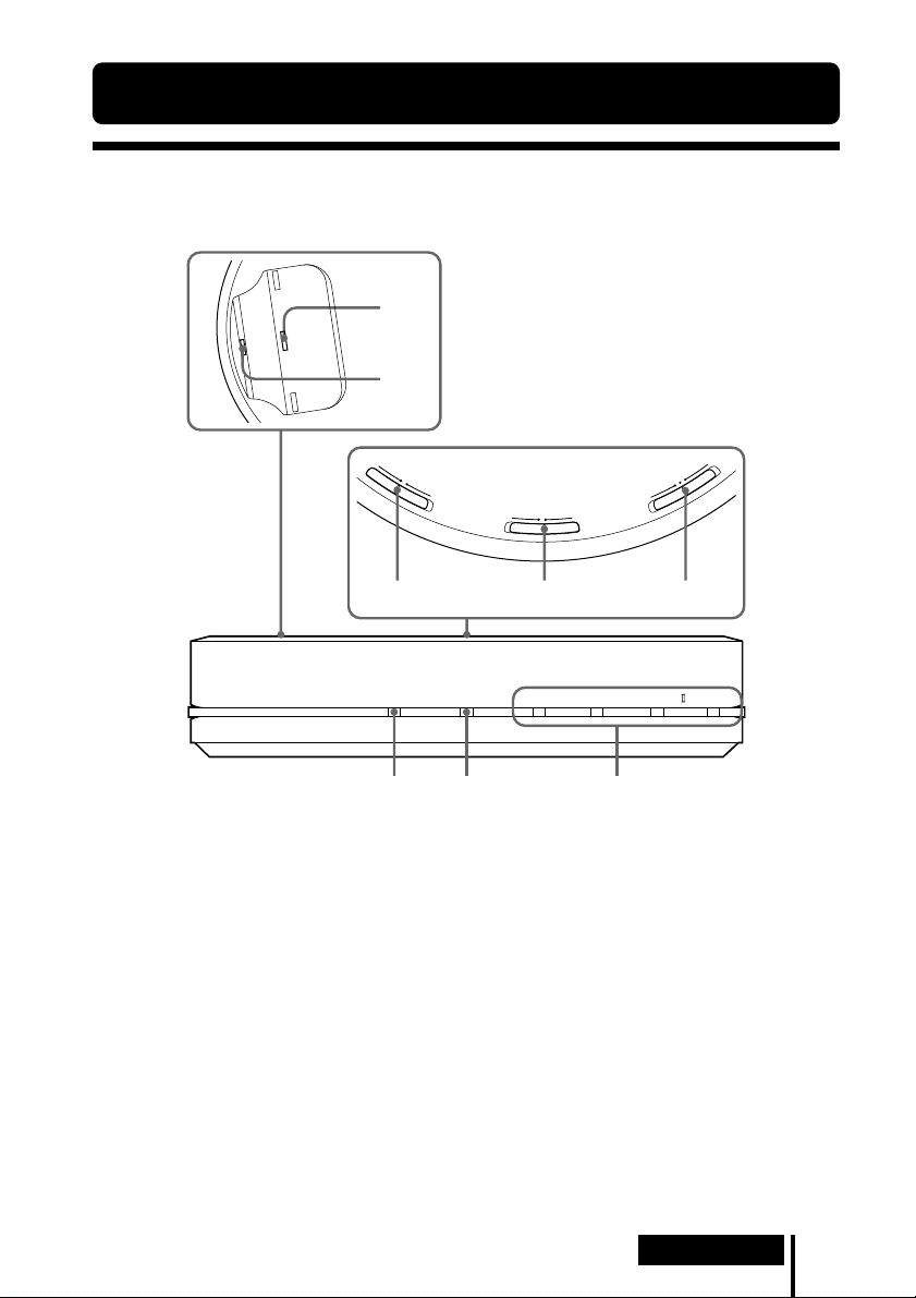
Ubicación y función de las piezas
Panel frontal del procesador
1
2
C
O
O
M
F
P
F
R
E
S
S
I
O
N
O
N
I
N
T
P
C
U
E
L
T
E
S
A
L
N
A
A
T
I
L
G
O
I
G
D
U
M
A
M
T
E
C
N
E
I
F
C
F
E
F
F
O
C
I
S
1 Pin de contacto
2 Palanca de carga
3 Selector COMPRESSION
(Para obtener más información, consulte
la página 20.)
4 Selector INPUT SELECT
Deslícelo para seleccionar la fuente de
entrada (DIGITAL/ANALOG).
5 Selector EFFECT
(Para obtener más información,
consulte la página 19.)
Deslícelo para seleccionar el campo de
sonido (MUSIC/OFF/CINEMA).
3
CHG RF DTS
6
7 8
6 Indicador CHG
Se ilumina en rojo durante la carga.
7 Indicador RF
Se ilumina en azul cuando se emiten
señales de radiofrecuencia.
8 Indicador DECODE MODE
(Para obtener más información,
consulte la página 20.)
45
DOLBY DIGITAL DOLBY PRO LOGIC MPEG-2 AAC
Preparación
ES
7
Page 68

Panel trasero del procesador
LLINE IN
TUNE/ID SET
0dB -8dB
12 3 456
R
ATT
DIGITAL IN DIGITAL OUT
DC IN 9V
(THROUGH)
1 Botón TUNE/ID SET
(Consulte las páginas 21 y 23 para obtener
más información.)
Pulse este botón cuando se deteriore la
recepción o cuando utilice auriculares
adicionales.
2 Selector ATT (atenuador)
Ajuste este selector en “0 dB” si el
volumen es demasiado bajo para la
entrada analógica. Normalmente este
selector debe estar ajustado en “–8 dB”.
3 Tomas LINE IN
(Para obtener más información,
consulte la página 16.)
Conecte a estas tomas las tomas de salida
de audio del componente de audio o
video (vendido por separado) como, por
ejemplo, un reproductor de cintas de
video o un televisor.
ES
8
Preparación
4 Toma DIGITAL IN
(Para obtener más información,
consulte la página 15.)
Conecte a esta toma una unidad de DVD,
un receptor de satélite/televisión digital u
otro componente digital (vendido por
separado).
5 Toma DIGITAL OUT
(Para obtener más información,
consulte la página 15.)
La integridad de la señal digital de los
componentes conectados se mantiene una
vez instalados.
6 Toma DC IN 9V
Conecte a esta toma el adaptador de
alimentación de ca suministrado.
(Asegúrese de utilizar el adaptador de
alimentación de ca suministrado. Si utiliza
productos con distintas polaridades de
clavija u otras características, puede
provocar un mal funcionamiento.)
Page 69
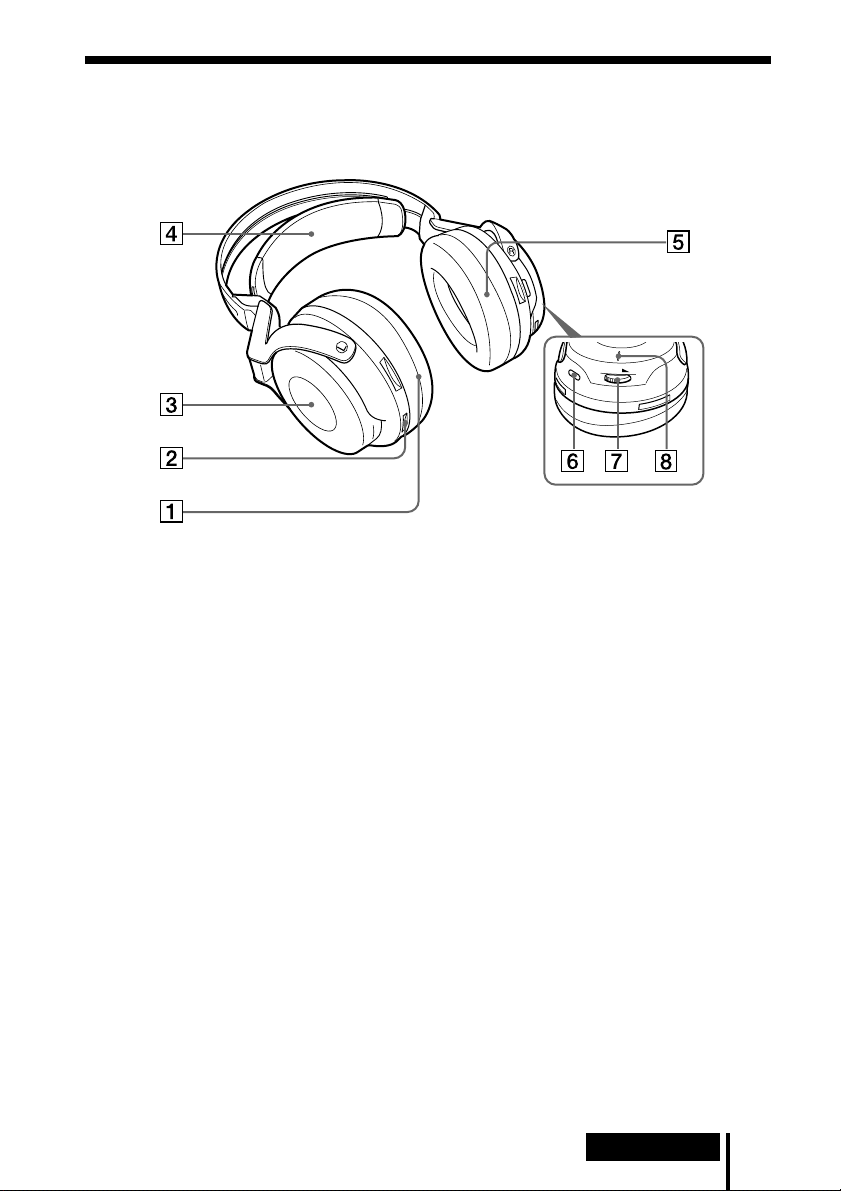
Descripción de las piezas de los auriculares
T
U
N
E
/ I
D
S
E
T
T
U
N
E
/ I
V
O
L
D
S
E
T
1 Almohadilla (izquierda)
2 Punto de contacto
3 Compartimiento de las pilas
El compartimiento de las pilas sirve
solamente para la pila recargable de
hidruro metálico de níquel (suministrada)
o para pilas alcalinas (tamaño AA)
disponibles en el mercado.
4 Cinta autoajustable para la cabeza
Los auriculares se encienden
automáticamente al colocárselos.
5 Almohadilla (derecha)
6 Botón TUNE/ID SET
(Consulte las páginas 21 y 23 para obtener
más información.)
Pulse este botón cuando se deteriore la
recepción o cuando utilice auriculares
adicionales.
7 Control VOL (volumen)
Utilícelo para ajustar el volumen.
8 Indicador POWER
Al tirar de la cinta autoajustable, el
indicador se ilumina en azul si queda
energía en la pila.
Preparación
ES
9
Page 70

Carga de la pila recargable de hidruro de
níquel-metal suministrada
La pila recargable de hidruro de níquel-metal suministrada no estará cargada la
primera vez que vaya a utilizarla. Asegúrese de cargarla antes de utilizarla.
Para cargar los auriculares, colóquelos sobre el procesador.
Inserción de la pila recargable de hidruro de
níquel-metal suministrada
1 Abra la tapa del compartimiento de
la pila del receptáculo izquierdo.
La tapa del compartimiento de la pila
se desprende.
Receptáculo
izquierdo
2 Inserte la pila recargable de hidruro de
níquel-metal suministrada en el
compartimiento de la pila de modo que el
terminal 3 de la pila coincida con la marca
3 del compartimiento.
No intente cargar otro tipo de pila con esta
unidad.
Nota
El compartimiento de la pila tiene una lengüeta en el lado # que mantiene la pila en su
lugar. Cuando inserte la pila, introduzca primero el terminal #.
3 Cierre la tapa del compartimiento
de las pilas.
ES
10
Preparación
2
1
Page 71

Carga
1 Si el adaptador de alimentación de ca viene equipado con un interruptor de
activación/desactivación, ajústelo en ON.
El procesador recibe la energía.
Interruptor de
activación/desactivación
2 Conecte el adaptador de alimentación de ca suministrado al procesador.
a un tomacorriente
Procesador
de ca
a la toma
DC IN 9V
Notas
• Asegúrese de utilizar el adaptador de alimentación de ca suministrado. Si utiliza
adaptadores de ca con distintas polaridades de clavija u otras características, puede
provocar una falla en el producto.
Clavija de polaridad unificada
Adaptador de
alimentación
de ca
(suministrado)
• Asegúrese de utilizar siempre el adaptador de alimentación de ca suministrado.
Incluso los adaptadores de alimentación de ca con un mismo voltaje y
polaridad de clavija pueden dañar este producto debido a la capacidad de
corriente u otros factores.
(continuación)
Preparación
11
ES
Page 72

3 Coloque los auriculares en el procesador de modo que los pines de contacto
encajen en los orificios de contacto del procesador y asegúrese de que se
ilumine el indicador CHG.
La carga completa de la pila requiere aproximadamente 3 horas (el indicador
CHG se apaga una vez finalizada).
Asegúrese de sujetar los auriculares con ambas manos cuando los coloque en el
procesador para que los receptáculos derecho e izquierdo queden en posición
horizontal; sitúe los auriculares en posición vertical sobre el procesador. Con la
presión, la palanca de carga baja y el pin de contacto se levanta. Cuando el pin de
contacto del procesador entra en contacto con el punto de contacto de los
auriculares, el indicador CHG se ilumina.
Punto de
contacto
Palanca
de carga
Pin de
contacto
Receptáculo izquierdo
Receptáculo
derecho
Indicador CHG
Si el indicador CHG no está encendido
• Asegúrese de cerrar la tapa del compartimiento de la pila. La función de carga de la
pila no se activa si la tapa no está bien cerrada.
• Compruebe si los receptáculos derecho e izquierdo están bien colocados en el
procesador.
• El indicador no se ilumina si el punto de contacto de los auriculares no está en
contacto con el pin de contacto del procesador. En ese caso, retire los auriculares del
procesador y vuelva a colocarlos sobre éste para que se ilumine el indicador.
• Asegúrese de que la pila recargable de hidruro de níquel-metal se encuentra en el
compartimiento de la pila. Las pilas secas no son recargables.
• Si la pila recargable está dañada o si sus terminales 3 y # no encajan bien con los
del compartimiento de la pila, el indicador CHG parpadea.
12
ES
Preparación
Page 73

Para recargar la pila de los auriculares después de su uso
Coloque los auriculares sobre el procesador después de utilizarlos. El indicador CHG
se ilumina, el indicador RF se apaga y se inicia el proceso de carga.
Puesto que el temporizador incorporado detecta cuándo finaliza la carga (requiere
aprox. 3 horas), no es necesario quitar los auriculares del procesador cuando ésta
finaliza.
Notas
• El procesador se apaga automáticamente durante la carga de la pila.
• Por motivos de seguridad, este sistema se ha diseñado para cargar solamente la pila recargable
del tipo BP-HP2000 suministrada. Recuerde que no se pueden cargar otros tipos de pilas
recargables con este sistema.
• Si se instalan pilas secas, no se pueden cargar.
• No intente utilizar la pila recargable BP-HP2000 suministrada en otros componentes. Está
diseñada para utilizarse solamente en este sistema.
• Realice la carga a una temperatura ambiental de entre 0 ºC y 40 ºC. De lo contrario, es posible
que la pila no se cargue por completo.
• No toque los pines de contacto del procesador. Si un pin de contacto se ensucia es posible que
no se pueda realizar la carga.
• Si hay polvo en el pin de contacto del procesador o en el punto de contacto de los auriculares,
es posible que no pueda realizarse la carga. Límpielos con un hisopo de algodón.
Tiempo de carga y uso
Tiempo de carga aproximado Tiempo de uso aproximado*
2
3 horas*
*1 A 1 kHz, salida de 1 mW +1 mW
*2 Horas necesarias para cargar completamente una pila vacía
*3 El tiempo puede variar en función de la temperatura o las condiciones de uso.
7 horas*
3
1
Comprobación de la energía de la pila
Tire hacia arriba de la cinta autoajustable y compruebe
el estado del indicador POWER situado en el
receptáculo derecho. Si el indicador se ilumina en azul
significa que todavía se puede seguir utilizando la
pila.
Si el indicador POWER no se ilumina, cargue la pila
recargable o instale nuevas pilas alcalinas.
Indicador
POWER
Nota
La pila recargable de hidruro de níquel-metal debe sustituirse por una nueva si solamente dura
la mitad del tiempo previsto tras realizar una carga completa. Esta pila no se puede adquirir en
el mercado. Puede solicitarla en el establecimiento en el que adquirió el sistema o a su
distribuidor de Sony más cercano.
Preparación
13
ES
Page 74

Uso de los auriculares con pilas alcalinas
(vendidas por separado)
También puede utilizar pilas alcalinas (tamaño AA) disponibles en el mercado para
alimentar los auriculares. Instálelas como se describe en “Inserción de la pila
recargable de hidruro de níquel-metal suministrada” (página 10).
Cuando se instalan pilas secas, la función de carga de las pilas está desactivada.
Duración de las pilas
Pilas Horas aprox.*
Pilas alcalinas de Sony 5 horas*
LR6(SG)
*1 A 1 kHz, salida de 1 mW +1 mW
*2 El tiempo indicado puede variar en función de la temperatura y las condiciones de uso.
Notas acerca de las pilas
• No cargue una pila seca.
• No transporte las pilas de modo que entren en contacto con monedas u objetos metálicos. Éstas
pueden generar calor si sus terminales positivo y negativo crean accidentalmente un
cortocircuito.
• Si no va a utilizar la unidad durante un largo período de tiempo, retire las pilas para evitar que
se produzcan daños por fugas o corrosión de las mismas.
1
2
14
ES
Preparación
Page 75

1 Conexión
Conexión del sistema de auriculares
Conexión del procesador a componentes
digitales
Utilice el cable óptico de conexión digital suministrado para conectar la toma de
salida digital óptica*
digital u otro componente digital*
1
de una unidad de DVD, un receptor de satélite/televisión
2
a la toma DIGITAL IN (negra) del procesador.
Puede que sea necesario ajustar el componente de AV conectado para la salida digital
óptica. Consulte el manual de instrucciones del dispositivo conectado.
Cuando conecte el procesador a un amplificador de AV, etc., conecte la toma
DIGITAL OUT (roja) y la toma de entrada digital óptica externa mediante el cable
óptico de conexión digital (se vende por separado).
Procesador
A la toma
DIGITAL
OUT (roja)
A la toma
DIGITAL IN (negra)
Cable de conexión digital óptica
(suministrado)
Haga coincidir la orientación del clavija con
la toma e inserte el clavija hasta que quede
bien fijada en su lugar.
Notas
•El cable de conexión digital óptica es un dispositivo de una gran precisión y es sensible a golpes
y a presión externa. Por lo tanto, tenga cuidado cuando inserte y retire el clavija del cable.
• La entrada digital del procesador no admite frecuencias de muestreo de 96 kHz. Ajuste la
configuración de la salida digital de la unidad de DVD a 48 kHz cuando utilice este sistema.
Puede que se oiga ruido cuando se reciba una señal digital de 96 kHz.
Cable óptico de conexión
digital (se vende por
separado)
A la toma de entrada
digital óptica
A la toma de salida
digital óptica
Equipo con terminal de
entrada digital óptica como
un amplificador de AV
Unidad de DVD, receptor de
satélite/televisión digital u otro
componente digital que disponga
de una toma de salida digital
óptica.
*1Si el equipo conectado admite solamente salidas PCM, todos los efectos de sonido envolvente
serán procesados por DOLBY PRO LOGIC II.
*2No se garantiza que la conexión a la toma de salida digital óptica de una computadora
funcione con este sistema.
(continuación)
Conexión
15
ES
Page 76

DTS
• Para reproducir DVD grabados en formato de audio DTS se requiere una unidad de DVD
compatible con DTS. (Si desea obtener más información, consulte el manual de instrucciones
de su unidad de DVD.)
• Si reproduce CD grabados en formato DTS, es posible que se oigan ruidos al avanzar y
rebobinar con rapidez. No se trata de una falla de funcionamiento.
• Si la salida digital DTS está ajustada en “OFF” en la unidad de DVD, es posible que no se oiga
ningún sonido aunque se haya seleccionado la salida DTS en el menú del DVD.
• Si se conecta analógicamente una unidad de DVD con este equipo, no se oirá ningún sonido.
En ese caso, utilice una conexión digital.
Cables de conexión (se venden por separado)
Utilice el cable óptico de conexión digital POC-15AB (mini clavija y clavija rectangular) si
conecta la minitoma de salida digital óptica a reproductores de DVD portátiles, reproductores de
CD portátiles u otros componentes digitales a la toma DIGITAL IN.
Notas sobre el cable de conexión digital óptica
• No deje caer objetos sobre el cable de conexión digital
óptica ni lo exponga a golpes.
• Sujete el clavija para conectar o desconectar el cable.
• Asegúrese de que los extremos del cable de conexión
El radio de plegado del cable de
conexión digital óptica no debe ser
inferior a 25 mm.
digital óptica se mantienen siempre limpios. El polvo en
los extremos del cable puede deteriorar su rendimiento.
• Cuando guarde el sistema, coloque el capuchón al
25 mm
extremo del clavija y procure no doblar el cable de
conexión digital óptica con un radio de plegado inferior
a 25 mm.
Conexión del procesador a componentes
analógicos
Utilice un cable de audio (se vende por separado) para conectar las tomas de salida de
audio de la videograbadora, el televisor u otro componente a las tomas LINE IN (L/
R) del procesador.
16
ES
Audio derecho
(R, rojo)
Conexión
Procesador
A las tomas
LINE IN
Audio
izquierdo
(L, blanco)
Cable de audio
(vendido por separado)
A las tomas de
salida de audio
Audio
izquierdo
(blanco)
Audio derecho
(rojo)
Videograbadora, televisor
u otros componentes
Page 77
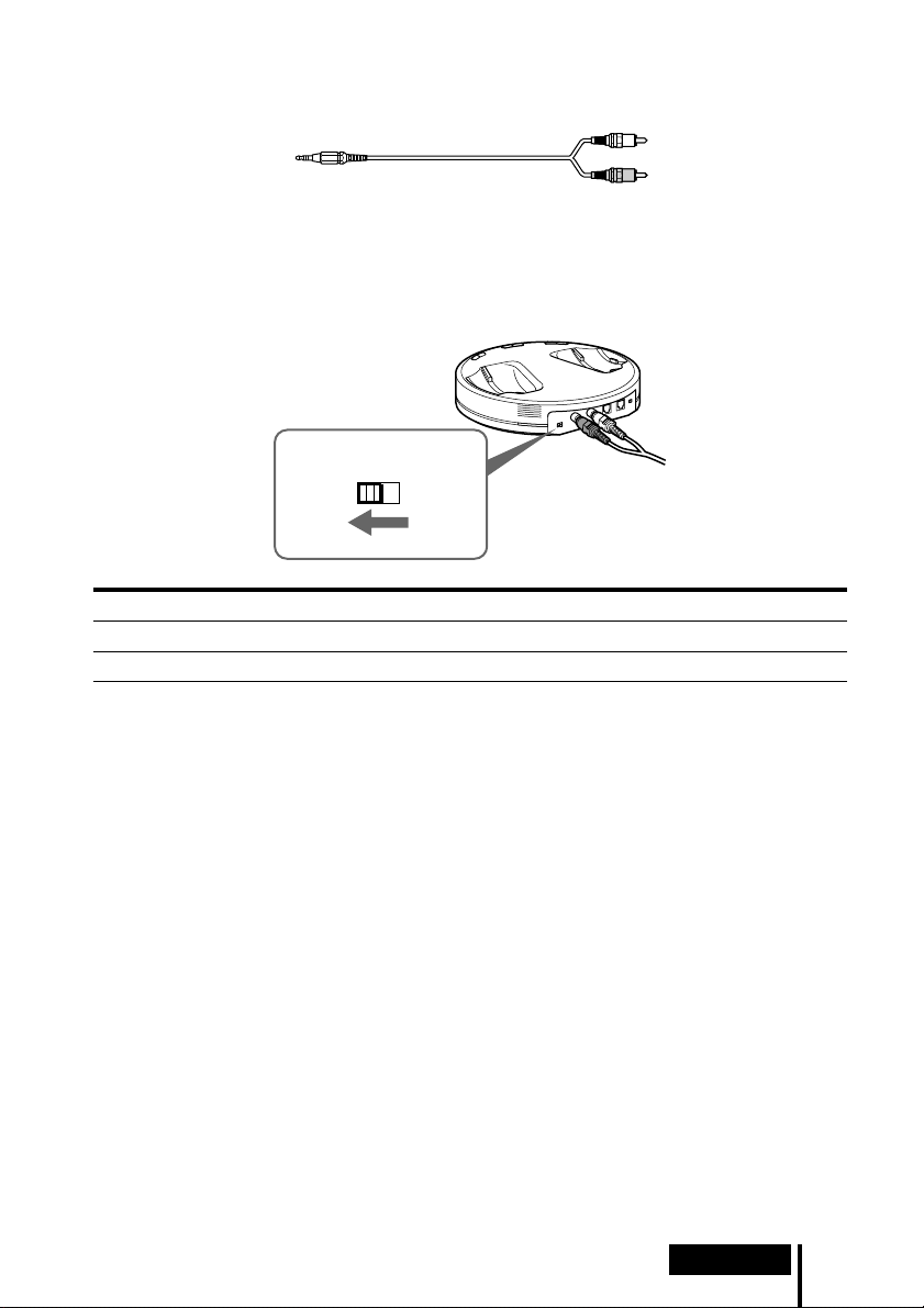
Cables de conexión (se venden por separado)
Utilice el cable (mini clavija estéreo y 2 clavijas de terminales) si conecta una minitoma estéreo
(toma de salida de línea o toma de auriculares) a las tomas LINE IN.
En este caso, ajuste el volumen del reproductor en un nivel medio. Si el volumen del reproductor
se ajusta demasiado bajo, se pueden producir ruidos.
Ajuste del nivel de entrada
Si el volumen es demasiado bajo utilizando una entrada analógica, ajuste el selector
ATT (atenuador) en la posición “0 dB”.
AT T
0dB -8dB
Ajuste Componentes conectados
0 dB
–8 dB Otros componentes (ajustes iniciales)
Televisor, componentes portátiles y otros componentes con nivel de salida bajo
Notas
• Asegúrese de bajar el volumen antes de ajustar el selector ATT.
• Si la entrada de audio a las tomas LINE IN se distorsiona (a veces, se puede oír ruido al mismo
tiempo), ajuste el selector ATT en “–8 dB”.
Conexión
17
ES
Page 78

1 Operación
Escuchar el sonido de un componente
conectado
Antes de empezar, asegúrese de leer la sección “Conexión
del sistema de auriculares” (páginas 15 a 17) y realice las
conexiones adecuadas.
1 Encienda el componente conectado al procesador.
Unidad de DVD, receptor de
satélite/televisión digital u
otro componente de audio o
video
2 Retire los auriculares del procesador.
El procesador se enciende automáticamente y el indicador RF parpadea durante
aproximadamente 5 segundos. El procesador detecta automáticamente la
frecuencia óptima de transmisión en función de las condiciones de la sala.
Cuando se inicia la emisión de señales desde el procesador, el indicador RF se
ilumina. A continuación se ilumina el indicador DECODE MODE en función de
la entrada de señales de audio desde el componente de audio o video conectado y
del ajuste del selector EFFECT.
Sistema de transmisión de señales
Esta unidad utiliza un sistema de transmisión patentado con una frecuencia de 2,4 GHz.
Con este sistema inalámbrico podrá disfrutar de sonido no comprimido.
POWER
3 Colóquese los auriculares.
El indicador POWER se ilumina en azul y los auriculares se encienden
automáticamente.
Asegúrese de hacer coincidir los lados derecho e izquierdo de los auriculares con
las orejas y utilizarlos en el ángulo adecuado, de modo que las funciones de
conexión y desconexión automática funcionen correctamente. Empezará a oír
sonido en los auriculares aproximadamente 3 segundos después de ponérselos.
Indicador
POWER
ES
18
Operación
Page 79
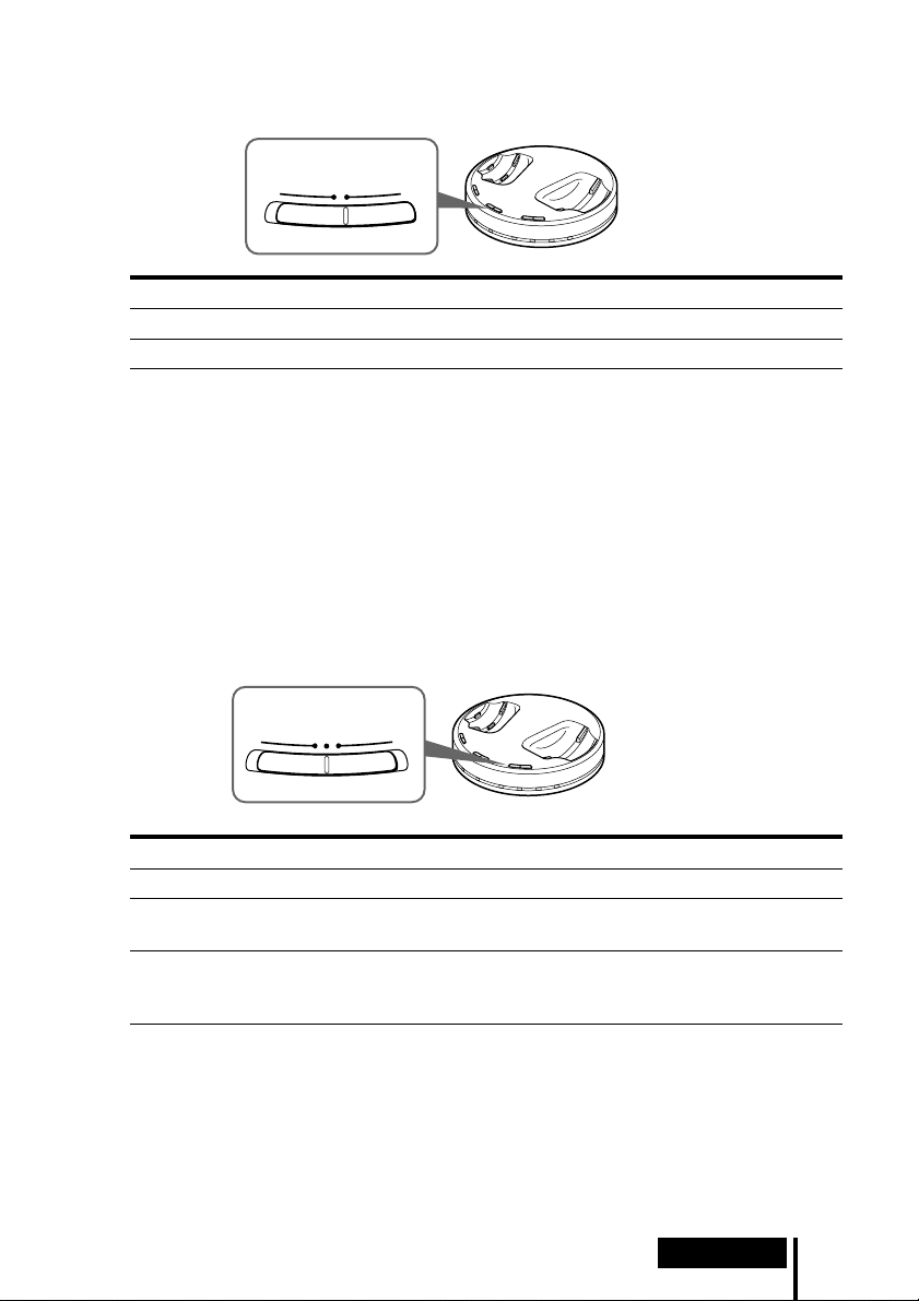
4 Deslice el selector INPUT SELECT para seleccionar el componente que desee
escuchar.
I
N
P
U
A
N
A
L
O
Posición del selector Fuente de sonido seleccionada
DIGITAL Sonido del componente conectado a la toma DIGITAL IN.
ANALOG Sonido del componente conectado a las tomas LINE IN.
Nota
Para escuchar fuentes de sonido audio dual (MAIN/SUB), conéctelo a las tomas LINE IN y,
a continuación, seleccione la fuente de sonido que desee escuchar en el reproductor, en el
televisor o en otro componente.
T
C
E
L
T
E
S
L
A
T
I
G
I
G
D
5 Inicie la reproducción del componente seleccionado en el paso 4.
6 Deslice el selector para seleccionar el campo de sonido que desee, EFFECT o
COMPRESSION.
Selector EFFECT
T
E
C
F
F
M
E
U
S
I
C
O
F
A
M
E
N
I
C
F
Posición del selector Campo de sonido y fuente de sonido adecuada
OFF Reproducción normal de los auriculares.
CINEMA Produce el tipo de sonido envolvente que se encuentra en una típica
MUSIC Produce el tipo de campo de sonido que se encuentra en una sala de
sala de cine. Adecuado para fuentes de sonido de cine.
audición con buena acústica. Adecuado para fuentes de sonido de
música.
Nota
El volumen de los auriculares puede variar en función de la señal de entrada y del ajuste del
selector EFFECT.
(continuación)
Operación
19
ES
Page 80

Selector COMPRESSION
C
O
M
O
F
F
N
O
I
P
S
R
S
E
N
O
Posición del selector Efecto de reproducción
OFF Cuando el selector EFFECT está seleccionado, el modo de sonido
ON Esta función mantiene un nivel global en el material del programa:
Ilustración del proceso de compresión
cambia al efecto seleccionado.
se atenúan los sonidos explosivos y aumenta el volumen de los
niveles más bajos (conversaciones, etc.)
Nivel
estridente
Nivel en el que
resulta fácil
entender
Nivel en el
que resulta
Compresión de rango dinámico
mediante un procesador digital de
señales (DSP) incorporado
difícil
entender
Indicadores DECODE MODE
El procesador identifica automáticamente el formato de la señal de entrada de audio, con lo
que se ilumina el indicador correspondiente. Cambie el audio entre Dolby digital, DTS,
MPEG-2 AAC, etc., en los equipos conectados (unidad de DVD, receptor de satélite/
televisión digital, etc.).
• DOLBY DIGITAL: señal de entrada grabada en formato DOLBY DIGITAL.
• DOLBY PRO LOGIC II: señal de entrada analógica, señal PCM de entrada digital o señal
de 2 canales de entrada de Dolby Digital procesada por DOLBY PRO LOGIC II.
(Si el campo de sonido se ajusta en “OFF”, DOLBY PRO LOGIC II no lo procesa.)
• DTS: señal de entrada grabada en formato DTS.
• MPEG-2 AAC: señal de entrada grabada en formato MPEG-2 AAC.
Nota
Si el equipo conectado a la toma DIGITAL IN no reproduce (avance rápido, rebobinado,
etc.), puede que el indicador DECODE MODE no se ilumine correctamente.
ES
20
Operación
Page 81

7 Ajuste del volumen.
V
O
L
Subir el
volumen
Notas
• Cuando mire películas, tenga cuidado de no subir demasiado el volumen en escenas
silenciosas, ya que cuando se pase a una escena con ruido podrían dañarse sus oídos.
• Es posible que oiga cierto ruido al desconectar el adaptador de alimentación de ca del
procesador antes de quitarse los auriculares.
Bajar el
volumen
Tiempo de transición entre modos
Cuando desplace los selectores en el procesador para cambiar de modo, el tiempo de
transición entre modos puede variar. Esto se debe a las diferencias en el control del
sistema entre modos.
Los auriculares se desconectarán automáticamente cuando se los quite
— Función de conexión y desconexión
automática
No tire de la cinta autoajustable cuando no utilice los
auriculares, ya que se consume energía de las pilas.
Cinta
autoajustable
para la cabeza
Si se oye un pitido a través de los auriculares
Se oirá un pitito repetidamente si las condiciones de recepción se deterioran cuando los
auriculares se encuentran fuera del área de transmisión de señales o si otro aparato
inalámbrico que utilice una frecuencia de 2,4 GHz o un microondas provocan interferencias.
Si el pitido no se detiene al acercarse al procesador, realice el procedimiento que se describe a
continuación para que el procesador vuelva a detectar la frecuencia óptima de transmisión.
1 Presione TUNE/ID SET una vez en el procesador.
El indicador RF parpadea y el procesador detecta
automáticamente la frecuencia óptima. Una vez
realizada la detección, el indicador RF se ilumina
y se inicia la emisión.
2 Presione TUNE/ID SET una vez en los
auriculares.
Los auriculares detectan automáticamente la
frecuencia del procesador. El pitido se detiene
cuando los auriculares empiezan a recibir
señales.
(continuación)
Operación
21
ES
Page 82

Área de transmisión de señales de radiofrecuencia
El área de transmisión de señales de radiofrecuencia desde el procesador es de
aproximadamente 30 m.
El procesador detecta automáticamente la frecuencia óptima al retirar los auriculares
del mismo. Es posible que el sonido se interrumpa si los auriculares se encuentran
fuera del área de transmisión de señales de radiofrecuencia o si las condiciones de
recepción se deterioran. En ese caso, acérquese al procesador o pulse TUNE/ID SET
en el procesador y en los auriculares para que vuelvan a detectar la frecuencia óptima.
Consulte la sección “Si se oye un pitido a través de los auriculares” (página 21) para
obtener información acerca de cómo detectar la frecuencia óptima.
Notas
• Puesto que este sistema transmite señales a 2,4 GHz, es posible que el sonido se interrumpa si
se producen interferencias. Este problema se debe a las características de la frecuencia de radio
y no a una falla de funcionamiento.
• El ruido que se oye a través de los auriculares puede variar en función de la posición del
procesador y de las condiciones de la sala. Es recomendable colocar el procesador en la
ubicación en la que genere el sonido más claro.
• Es posible que el sonido se interrumpa si el procesador se utiliza con otros aparatos
inalámbricos que utilicen una frecuencia de 2,4 GHz o con un microondas.
Si no se recibe ninguna señal de audio durante 5 minutos
La transmisión de señales de radiofrecuencia desde el procesador se detiene
automáticamente si no se recibe ninguna señal de audio durante 5 minutos. Al recibir
de nuevo señales de audio, las señales de radiofrecuencia vuelven a transmitirse
automáticamente. La transmisión de señales de radiofrecuencia puede detenerse si
durante 5 minutos se recibe un sonido extremadamente bajo. Si esto sucede, aumente
el volumen del componente de audio o video conectado y disminuya el volumen de
los auriculares. Si se emite ruido de señal desde un componente conectado a las tomas
LINE IN, es posible que la transmisión de señales de radiofrecuencia no se detenga.
Sugerencia
Si la transmisión de señales de radiofrecuencia desde el procesador se detiene al no recibir
señales de audio durante 5 minutos, se transmitirán automáticamente al volver a recibir señales
de audio.
El indicador RF parpadea y el procesador detecta la frecuencia óptima para la transmisión. Si la
frecuencia de transmisión cambia después de que se haya iluminado el indicador RF y no se oye
ningún sonido, pulse el botón TUNE/ID SET de los auriculares una vez y sintonice la nueva
frecuencia.
Notas
• Los auriculares deben utilizarse dentro del área de transmisión de señales de radiofrecuencia
(consulte la sección “Área de transmisión de señales de radiofrecuencia”).
• El efecto de sonido envolvente puede que no se obtenga de fuentes que no incorporen video
como, por ejemplo, discos CD de música.
• Este sistema simula la media HRTF* igual en la mayoría de las personas. Sin embargo, el efecto
puede diferir de una persona a otra ya que la media HRTF puede variar entre personas.
* Head Related Transfer Function
ES
22
Operación
Page 83

Uso de auriculares adicionales
El uso de auriculares inalámbricos MDR-RF6000 adicionales (vendidos por separado)
en este sistema permite que varias personas puedan disfrutar a la vez de la
experiencia del sonido envolvente en forma inalámbrica.
Cargue los auriculares adicionales con el procesador de este sistema.
* Puede utilizarse un número ilimitado de auriculares dentro del área de transmisión
de señales de radiofrecuencia.
MDR-RF6000 (vendido
Procesador
Notas
• El procesador se apagará automáticamente durante la carga. Retire los auriculares del
procesador cuando utilice los otros auriculares.
• Esta unidad sólo es compatible con los auriculares MDR-RF6000, ya que utiliza un sistema de
transmisión digital inalámbrico de 2,4 GHz patentado.
Si utiliza auriculares adicionales
Todos los procesadores tienen su propio número de ID. Cuando utilice auriculares
inalámbricos MDR-RF6000 adicionales (vendidos por separado), asegúrese de ajustar el ID
del procesador con el de los auriculares; de lo contrario, los auriculares no funcionarán.
por separado)
1 Retire los auriculares del procesador.
El procesador se enciende automáticamente.
2 Póngase los auriculares.
Los auriculares se encienden automáticamente.
Nota
Cargue la pila de los auriculares adicionales antes de ajustar sus ID o utilice pilas alcalinas
(tamaño AA) disponibles en el mercado.
3 Mantenga presionados TUNE/ID SET del procesador y de los auriculares al
mismo tiempo durante más de 3 segundos.
Se oirá repetidamente un pitido a través
de los auriculares y se iniciará el ajuste de
ID. Cuando el sonido cambia a un pitido
continuo significa que se ha ajustado el
número de ID para los auriculares.
Operación
23
ES
Page 84

Sustitución de las almohadillas de los auriculares
Las almohadillas de los auriculares pueden sustituirse. Si se ensucian o se deterioran,
reemplácelas tal como se muestra a continuación. Las almohadillas de los auriculares
no se comercializan. Puede solicitar recambios en el establecimiento donde adquirió el
sistema o al distribuidor Sony más cercano.
1 Tire de la almohadilla vieja para extraerla.
2 Coloque la nueva almohadilla alrededor del receptáculo.
24
ES
Operación
Page 85

1 Información complementaria
Solución de problemas
Si surge algún problema al utilizar este sistema de auriculares, utilice la lista de
comprobación siguiente. Si el problema persiste, consulte con su distribuidor Sony
más cercano.
Problema Causa y solución
No se oye el sonido , Compruebe la conexión entre el procesador y el componente de AV.
, Compruebe que, cuando está seleccionada la entrada digital, la señal no se
recibe por error, en la toma de salida digital.
, Compruebe que la salida digital óptica de los componentes de AV conectados
está en “ON” cuando está seleccionada la entrada digital.
, Encienda el componente de AV conectado al procesador e inicie la
reproducción.
, Compruebe que el selector INPUT SELECT del procesador se ha ajustado en el
componente que desee escuchar.
, Si conecta el procesador a un componente de AV utilizando las tomas de los
auriculares, suba el volumen del componente de AV conectado.
, Asegúrese de que se ha colocado correctamente los auriculares.
, Suba el volumen de los auriculares.
, El indicador POWER de los auriculares de apaga.
• Cargue la pila recargable si está a punto de agotarse o bien sustituya las
pilas alcalinas por otras nuevas. Si el indicador POWER sigue apagado
después de cargar la pila, lleve los auriculares a un distribuidor de Sony.
, Intenta reproducir una pista de audio DTS en una unidad de DVD que no es
compatible con DTS.
• Utilice una unidad de DVD compatible con DTS o seleccione una pista de
audio Dolby Digital o PCM.
, Reproduce un disco de DVD grabado en DTS y el ajuste de salida digital de la
unidad de DVD (incluidas las máquinas de juegos) es “OFF.”
• Consulte el manual de instrucciones de la unidad de DVD y cambie el ajuste
de salida digital DTS a la opción “ON.”
, Reproduce un disco de DVD grabado en DTS y la unidad de DVD (incluidas
las máquinas de juegos) y el procesador están conectados analógicamente.
• Utilice la conexión digital. (Es posible que el sonido analógico no pueda
reproducirse desde la unidad de DVD.)
, El ID del procesador no se ha ajustado para los auriculares adicionales.
, Los auriculares adicionales se están cargando.
• Retire los auriculares adicionales del procesador.
(continuación)
Información complementaria
25
ES
Page 86

Problema Causa y solución
Sonido distorsionado
o intermitente (a
veces con ruido)
Sonido bajo
Ruido de fondo alto
El sonido se corta
No se obtiene el
efecto del sonido
envolvente
El indicador
DOLBY DIGITAL
no se enciende
, Cargue la pila recargable si está a punto de agotarse, o bien sustituya las pilas
alcalinas por otras nuevas. Si el indicador POWER sigue apagado después de
cargar la pila, lleve los auriculares a un distribuidor de Sony.
, Compruebe si algún aparato inalámbrico está utilizando la frecuencia de
2,4 GHz o si hay algún microondas cerca.
, Cambie la posición del procesador.
, Cuando esté seleccionada la entrada analógica, cambie el selector ATT en el
procesador a “–8 dB”.
, Si conecta el procesador a un componente de AV utilizando la toma de los
auriculares, baje el volumen del componente de AV conectado.
, Si utiliza fuentes de audio DTS, ajuste el selector EFFECT del procesador en el
modo “CINEMA” o “MUSIC” (página 19, 20).
, Cuando esté seleccionada la entrada analógica, cambie el selector ATT en el
procesador a “0 dB”.
, Si conecta el procesador a un componente de AV utilizando la toma de los
auriculares, suba el volumen del componente de AV conectado.
, Suba el volumen de los auriculares.
, Compruebe si algún aparato inalámbrico está utilizando la frecuencia de
2,4 GHz o si hay algún microondas cerca.
, Si conecta el procesador a un componente de AV utilizando la toma de los
auriculares, suba el volumen del componente de AV conectado.
, Cargue la pila recargable si está a punto de agotarse, o bien sustituya las pilas
alcalinas por otras nuevas. Si el indicador POWER sigue apagado después de
cargar la pila, lleve los auriculares a un distribuidor de Sony.
, El procesador deja de transmitir señales si no se reciben señales durante
5 minutos.
• Coloque el selector ATT del procesador en “0 dB”.
• Si conecta el procesador a un componente de AV utilizando la toma de los
auriculares, suba el volumen del componente de AV conectado.
, Ajuste el selector EFFECT del procesador en el modo “CINEMA” o “MUSIC”
(página 19, 20).
, El audio que se reproduce no es de señal multicanal.
•
El efecto de sonido envolvente no funciona en fuentes de sonido monofónico.
, El ajuste de salida de audio digital de la unidad de DVD (incluidas las
máquinas de juegos) puede ser “PCM.”
• Consulte el manual de instrucciones de la unidad de DVD y cambie el ajuste
(como, por ejemplo, “Dolby Digital/PCM” o “Dolby Digital”) para su uso
con componentes que tengan decodificadores Dolby Digital incorporados.
, Las señales de reproducción no se grabaron en formato Dolby Digital.
,
El audio del capítulo que se reproduce no corresponde a una señal Dolby Digital.
26
ES
Información complementaria
Page 87

Problema Causa y solución
El indicador
DOLBY PRO
LOGIC II no se
ilumina
El indicador DOLBY
PRO LOGIC II se
ilumina
El indicador DTS
no se ilumina
El indicador
MPEG-2 AAC no
se enciende.
No se puede cargar
la pila
El indicador CHG
parpadea.
La transmisión de
señales de
radiofrecuencia no
se detiene (si el
selector INPUT
SELECT del
procesador está
ajustado en
“ANALOG”).
, El selector EFFECT del procesador está ajustado en “OFF”.
, No se recibe señal de entrada analógica, señal PCM de entrada digital, señal
de 2 canales de entrada Dolby Digital ni señal de 2 canales MPEG-2 AAC 2.
, El selector EFFECT está ajustado en el modo “CINEMA” o “MUSIC”.
, Se recibe señal de entrada analógica, señal PCM de entrada digital, señal de 2
canales de entrada Dolby Digital o señal de 2 canales MPEG-2 AAC 2.
, El ajuste de salida digital DTS de la unidad de DVD (incluidas máquinas de
juego) es “OFF.”
• Consulte el manual de instrucciones de la unidad de DVD y cambie el ajuste
de salida digital DTS a la opción “ON.”
, Las señales de reproducción no se grabaron en formado DTS.
, El audio del capítulo que se reproduce no corresponde a una señal DTS.
, La unidad de DVD no es compatible con el formato DTS.
• Utilice una unidad de DVD compatible con DTS.
, Las señales de reproducción no se grabaron en formato MPEG-2 AAC.
, Compruebe si se enciende el indicador CHG. Si no lo hace, coloque
correctamente los auriculares en el procesador de modo que se encienda el
indicador CHG.
, Se han instalado pilas secas.
• Inserte la pila recargable de hidruro de níquel-metal suministrada.
, Hay instaladas pilas recargables distintas de la suministrada.
• Inserte la pila recargable de hidruro de níquel-metal suministrada.
, Hay polvo en el pin de contacto del procesador y en el punto de contacto de
los auriculares.
• Límpielos con un hisopo de algodón.
, Los terminales 3 y # de la pila recargable no coinciden con las marcas del
compartimiento de la pila.
• Inserte la pila recargable con la polaridad correcta.
, La pila recargable está dañada.
• Reemplácela por una nueva. La pila recargable del tipo BP-HP2000 no se
puede adquirir en el mercado. Puede solicitarla en el establecimiento en el
que adquirió el sistema o a su distribuidor Sony más cercano.
, El ruido de la señal se emite desde el componente analógico conectado.
• Desconecte el componente analógico conectado o ajuste el selector INPUT
SELECT del procesador en “DIGITAL,” y asegúrese de haber detenido la
reproducción del componente conectado a la toma DIGITAL IN.
(continuación)
Información complementaria
27
ES
Page 88

Problema Causa y solución
No se emite señal
desde la salida
digital óptica
No se puede
seleccionar el sonido
en dos idiomas
cuando se utiliza la
entrada digital. (Se
pueden oír a la vez
MAIN y SUB.)
Se oye un pitido
repetidamente.
, El procesador no recibe corriente.
• Conecte el procesador a una fuente de alimentación.
, No se oye el sonido de la reproducción de la unidad digital externa conectada
a la toma de entrada óptica.
• Compruebe que la unidad externa esté reproduciendo.
, Conecte la salida analógica a las tomas LINE IN y seleccione el sonido en el
componente conectado.
, Los auriculares no pueden recibir la señal del procesador.
• Muévase por el área de transmisión de señales de radiofrecuencia.
• Compruebe la conexión del procesador, el adaptador de alimentación de ca
y el tomacorriente de ca.
• Compruebe si hay algún aparato inalámbrico que utilice la frecuencia
2,4 GHz o algún microondas cerca del procesador y los auriculares.
• Cambie la posición del procesador.
, No se reciben señales de audio durante aproximadamente 5 minutos y no se
transmiten señales de radiofrecuencia.
• Reciba la señal de audio en el procesador y pulse TUNE/ID SET una vez en
los auriculares.
, Los auriculares adicionales se están cargando.
• Retire los auriculares adicionales del procesador.
28
ES
Información complementaria
Page 89

Precauciones
Seguridad
• No deje caer, golpee ni exponga el
procesador o los auriculares a golpes
fuertes de ningún tipo. Podría dañar el
producto.
• No desmonte ni intente abrir ninguna de
las piezas del sistema.
Fuentes de alimentación y ubicación
• Si no va a utilizar el sistema durante un
período de tiempo largo, desenchufe el
adaptador de alimentación de ca de la toma
de ca. Cuando retire el enchufe, sujete bien
el adaptador de alimentación de ca. No tire
del cable.
• No sitúe el sistema en ninguna de las
ubicaciones siguientes:
– Lugares expuestos a luz solar directa,
cerca de sistemas de calefacción o
ubicaciones con temperaturas
extremadamente altas
– Lugares polvorientos
– Superficies no estables o inclinadas
– Lugares expuestos a muchas vibraciones
– En el baño o ubicaciones similares
sometidas a mucha humedad
Limpieza
Utilice un paño suave ligeramente
humedecido con una solución de detergente
suave. No utilice disolventes como diluyentes,
bencina o alcohol, ya que pueden dañar la
superficie.
Si el producto se rompe
• Si el producto se rompe o un objeto extraño
entra en la unidad, desconecte la
alimentación inmediatamente y consulte
con su distribuidor Sony más cercano.
• Cuando lleve el sistema al distribuidor
Sony, asegúrese de llevar tanto el
procesador como los auriculares.
Los auriculares
Respeto por los demás
Si el volumen es demasiado alto, el sonido se
emite fuera de los auriculares. Tenga cuidado
de no subir demasiado el volumen porque
podría molestar a la gente de su alrededor.
Hay tendencia a subir el volumen cuando se
utiliza en lugares ruidosos. No obstante, por
motivos de seguridad, se recomienda
mantener el volumen a un nivel que le
permita oír los sonidos de su alrededor.
Información complementaria
29
ES
Page 90

Especificaciones
Procesador de sonido envolvente
digital (DP-RF6000)
Funciones del descodificador
Dolby Digital
Dolby Pro Logic II
DTS
MPEG-2 AAC
Función de sonido virtual
OFF
CINEMA
MUSIC
Función de compresión OFF
Sistema de modulación
Transportador de frecuencia de ondas
Distancia de transmisión
Respuesta de frecuencia
Índice de distorsión 1% o inferior (1 kHz)
Entradas de audio
Salida de audio Salida digital óptica
Requisitos de alimentación
Dimensiones Aprox. 182 × 38 ×
Masa Aprox. 345 g
ON
DSSS
2,412 a 2,462 GHz
Aprox. 30 m de
longitud máxima
12 a 22.000 Hz
(entrada digital,
frecuencia de
muestreo de 48 kHz)
Entrada digital óptica
(tipo rectangular) × 1
Entrada analógica
(
toma de pines
izquierdo/derecho) × 1
(tipo rectangular) × 1
9 V de cc (del
adaptador de
alimentación de ca
suministrado)
182 mm (an/al/prf)
Auriculares estéreo inalámbricos
(MDR-RF6000)
Rango de frecuencias de reproducción
Requisitos de alimentación
Masa Aprox. 360 g
De 12 a 22.000 Hz
Pila recargable de
hidruro de níquelmetal (suministrada) o
pilas alcalinas (tamaño
AA) disponibles en el
mercado
(incluida la pila
recargable de hidruro
de níquel-metal
suministrada)
Accesorios suministrados
Adaptador de alimentación
de ca (9 V) (1)
Pila recargable de hidruro de níquelmetal BP-HP2000 (2.100 mAh) (1)
Cable de conexión digital óptica
(clavija rectangular óptica y clavija
rectangular óptica, 1,5 m) (1)
Manual de instrucciones (este manual)
(1)
Accesorios recomendados
Cable de conexión digital óptico
POC-15AB (1,5 m) (mini enchufe y
enchufe rectangular)
El diseño y las especificaciones están sujetos a
cambios sin previo aviso.
30
ES
Información complementaria
Page 91

Page 92

Printed in Malaysia
 Loading...