

Page 1

MD Multi-Track
Recorder
3-858-580-12(1)
Operating Instructions
Mode d’emploi
Bedienungsanleitung
EN
F
D
T
MDM-X4
© 1996 by Sony Corporation
Page 2
WARNING
To prevent fire or shock
hazard, do not expose the
unit to rain or moisture.
This symbol is intended to alert the user
to the presence of uninsulated
“dangerous voltage” within the
product’s enclosure that may be of
sufficient magnitude to constitute a risk
of electric shock to persons.
This symbol is intended to alert the user
to the presence of important operating
and maintenance (servicing)
instructions in the literature
accompanying the appliance.
To avoid electrical shock, do
not open the cabinet. Refer
servicing to qualified
personnel only.
Do not install the appliance in a
confined space, such as a bookcase
or built-in cabinet because the mains
power switch (MAIN POWER) is
located on the rear panel.
This appliance is classified as a
CLASS 1 LASER product. The
CLASS 1 LASER PRODUCT
MARKING is located on the rear
exterior.
INFORMATION
This equipment has been tested and
found to comply with the limits for a
Class B digital device, pursuant to Part
15 of the FCC Rules.
These limits are designed to provide
reasonable protection against harmful
interference in a residential installation.
This equipment generates, uses, and can
radiate radio frequency energy and, if
not installed and used in accordance
with the instructions, may cause
harmful interference to radio
communications. However, there is no
guarantee that interference will not
occur in a particular installation. If this
equipment does cause harmful
interference to radio or television
reception, which can be determined by
turning the equipment off and on, the
user is encouraged to try to correct the
interference by one or more of the
following measures:
- Reorient or relocate the receiving
antenna.
- Increase the separation between the
equipment and receiver.
- Connect the equipment into an outlet
on a circuit different from that to
which the receiver is connected.
- Consult the dealer or an experienced
radio/TV technician for help.
CAUTION
You are cautioned that any change or
modifications not expressly approved in
this manual could void your authority
to operate this equipment.
Owner’s record
The model and serial numbers (name
plate) are located on the bottom of the
unit. Record the serial number in the
space provided below. Refer to them
whenever you call upon your Sony
dealer regarding this product.
Model No. MDM-X4
Serial No.
For the customers in Canada
This Class B digital apparatus meets all
requirements of the Canadian
Interference-Causing Equipment
Regulations.
Cet appareil numérique de la classe B
respecte toutes les exigences du
Réglement sur le matériel brouilleur du
Canada.
CAUTION
TO PREVENT ELECTRIC SHOCK, DO
NOT USE THIS POLARIZED AC PLUG
WITH AN EXTENSION CORD,
RECEPTACLE OR OTHER OUTLET
UNLESS THE BLADES CAN BE FULLY
INSERTED TO PREVENT BLADE
EXPOSURE.
Precautions
On safety
• Caution - The use of optical
instruments with this product will
increase eye hazard.
• Should any liquid or solid object fall
into the unit, unplug the unit and
have the unit checked by qualified
personnel before operating it any
further.
On power sources
• Before operating the unit, be sure that
the operating voltage of your unit is
identical with that of your local
power supply.
• Unplug the unit from the wall outlet
if it is not to be used for an extended
period of time. To disconnect the
cord, pull it out by grasping the plug.
Never pull the cord itself.
• AC power cord must be changed only
at the qualified service shop.
• The unit is not disconnected from the
AC power source (mains) as long as it
is connected to the wall outlet, even if
the unit itself has been turned off.
On placement
• Place the multi track recorder in a
location with adequate ventilation to
prevent heat buildup in the multi
track recorder.
• Do not place the unit in an inclined
position.
• Do not place the unit in locations
where it is:
– Extremely hot or cold
– Dusty or dirty
– Very humid
– Vibrating
– Subject to direct sunlight.
On cleaning the cabinet
Clean the cabinet, panels and controls
with a soft cloth lightly moistened with
a mild detergent solution. Do not use
any type of abrasive pad, scouring
powder or solvent such as alcohol or
benzine.
EN
2
Page 3

On repacking
Do not throw away the carton and the
packing material. This makes an ideal
container when transporting the unit.
When shipping the unit, repack it as it
was packed at the factory.
On operation
• If the multi track recorder is brought
directly from a cold to a warm
location , or is placed in a very damp
room, moisture may condense on the
lens inside the MD deck. Should this
occur, the system will not operate
properly. Remove the MD and leave
the system turned on for about an
hour until the moisture evaporates.
• When you move the system, take out
the disc.
On handling MDs
• Do not open the shutter to expose the
MD. Close the shutter immediately if
the shutter opens.
• Wipe the disc cartridge with a dry
cloth to remove dirt.
• Do not expose the MD to direct
sunlight or heat sources such as hot
air ducts, nor leave it in a car parked
in direct sunlight.
Protecting a recorded MD
To record-protect an MD, slide open the
tab at the side of the MD so the tab is
concealed.
In this position, the MD cannot be
recorded. To record on the MD, slide
close the tab.
On requesting repairs
The nameplate is located on the bottom
exterior.
If you have any question or problem
concerning your unit that is not covered
in this manual, please consult your
nearest Sony dealer.
About This Manual
The following icon is used in this
manual:
Indicates hints and tips for
making the task easier.
Welcome!
Thank you for purchasing the Sony MD
Multi-Track Recorder. Before operating
the unit, please read this manual
thoroughly and retain it for future
reference.
TABLE OF CONTENTS
Overview of MDM-X4
Standard Recording Procedures.................................................................................. 4
Names and Functions of Parts
The Mixer......................................................................................................................... 6
The Recorder ................................................................................................................... 8
The Display ................................................................................................................... 10
Input and Output Jacks ............................................................................................... 11
Connections and Signal Flow
Connections for Recording .........................................................................................13
Connecting MIDI Equipment .................................................................................... 14
MDM-X4 Signal Flow Diagram ................................................................................. 14
Monitoring
Monitoring Preparations ............................................................................................15
Monitoring Example .................................................................................................... 15
Setting Up the Operating Environment
System Settings ............................................................................................................. 17
Changing the Settings ................................................................................................. 18
Recording
Initial Recording ........................................................................................................... 19
Overdub Recording ..................................................................................................... 20
Auto Punch-In/Out Recording ................................................................................. 22
Manual Punch-In/Out Recording ............................................................................ 25
Mix Write Recording (Basics) .................................................................................... 27
Mix Write Recording (Applied Operations) ........................................................... 28
Editing Part of a Song (Track Edit)
Track Edit Overview ...................................................................................................31
Specifying the Locate Points ...................................................................................... 31
Copying a Part (Track Copy) ..................................................................................... 33
Moving a Part (Track Move) ...................................................................................... 34
Switching the Location of 2 Parts (Track Exchange) ............................................. 35
Erasing a Part (Track Erase) ....................................................................................... 36
Changing the Construction of a Song (Section Edit)
Section Edit Overview.................................................................................................38
Specifying the Locate Points ...................................................................................... 38
Moving a Section (Section Move).............................................................................. 39
Switching the Location of 2 Sections (Section Exchange) ..................................... 40
Inserting Another Section (Section Insert) .............................................................. 41
Deleting a Section (Section Delete) ........................................................................... 42
Editing Entire Songs (Song Edit)
Song Edit Overview .....................................................................................................43
Copying a Song (Song Copy) ..................................................................................... 43
Moving a Song (Song Move) ...................................................................................... 44
Changing the Song Order (Song Exchange)............................................................ 45
Dividing a Song (Song Divide) .................................................................................. 46
Connecting 2 Songs (Song Combine) ....................................................................... 47
Deleting a Song (Song Delete) ...................................................................................48
Naming a Song (Song Name) .................................................................................... 49
Editing the Entire Disc (Disc Edit)
Overview ....................................................................................................................... 50
Erasing the Disc Contents (Disc Erase) ....................................................................50
Naming the Disc (Disc Name) ................................................................................... 51
Synchronization with MIDI Equipment
Advantages of Using MIDI ........................................................................................52
MIDI Synchronization Using MTC ........................................................................... 52
MIDI Synchronization Using the MIDI Clock ........................................................ 53
Controlling This Unit from Other MIDI Components Using MMC ................... 55
Example of a MIDI System ......................................................................................... 56
Mixdown
Mixdown (Basics) ......................................................................................................... 57
Mixdown (Applied Operations) ................................................................................ 58
Additional Information
Troubleshooting ........................................................................................................... 60
Display Message List ................................................................................................... 60
System Limitations of MDs ........................................................................................ 61
Specifications ................................................................................................................ 61
Glossary ......................................................................................................................... 63
Block Diagram .............................................................................................................. 64
MIDI Implementation Chart ...................................................................................... 65
Track Sheet ................................................................................................... Back Cover
EN
F
EN
3
Page 4
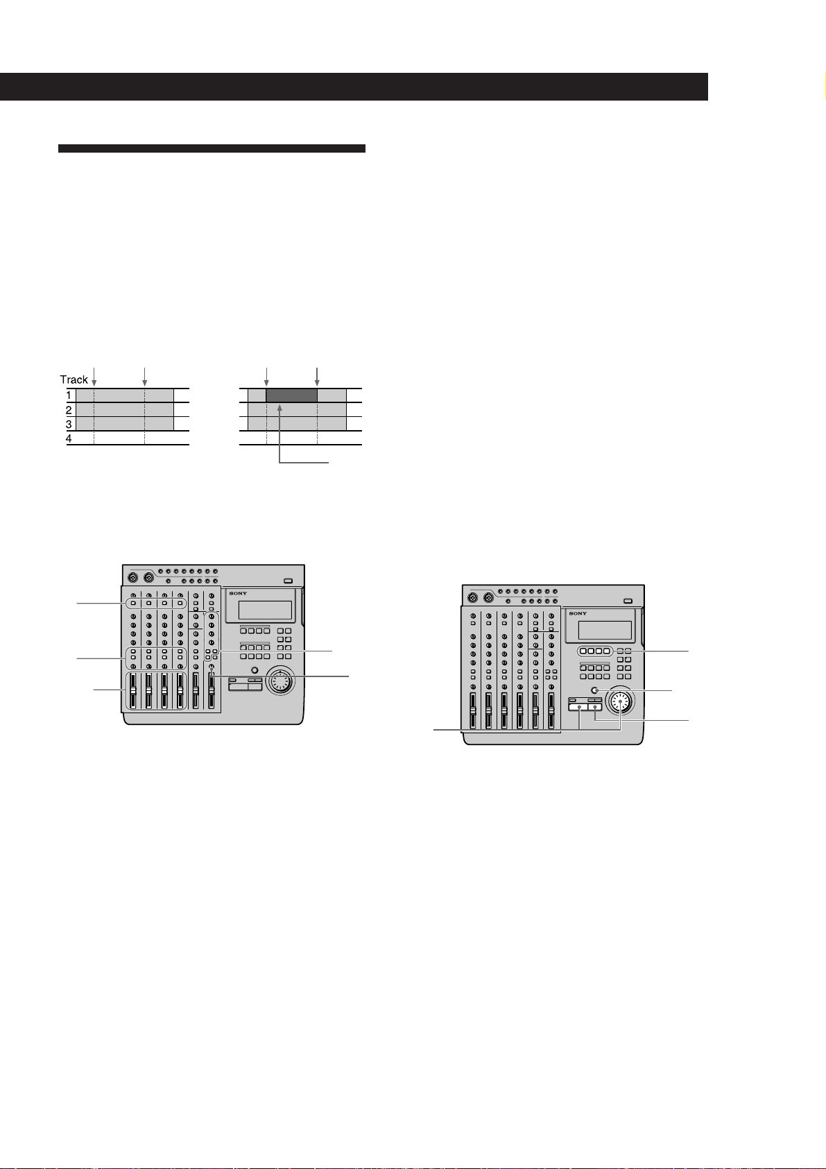
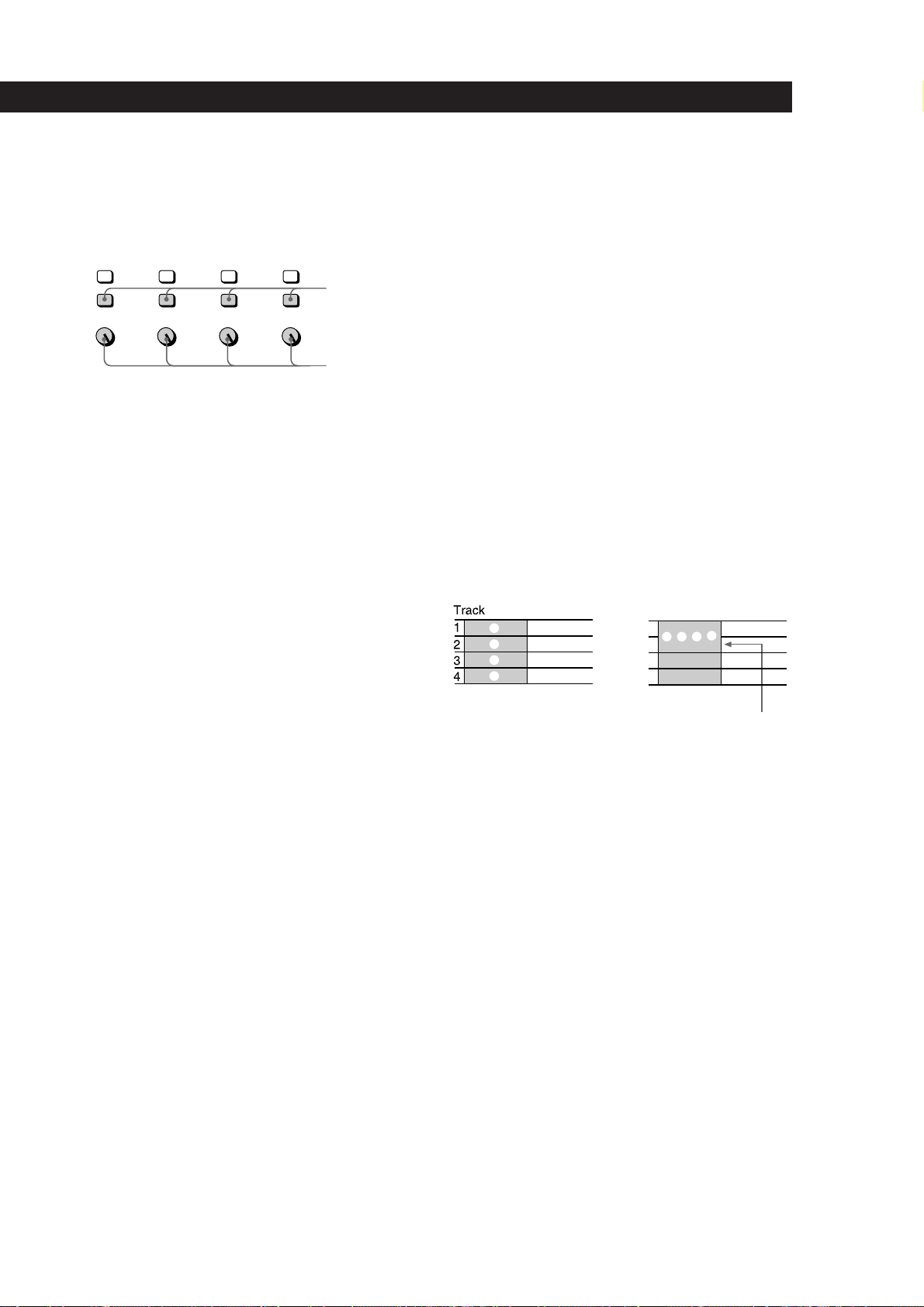
Overview of MDM-X4
Standard Recording
Procedures
The MDM-X4 is an integrated multichannel recorder/
mixer that can record up to 4 tracks using MD-DATA
discs. In addition to 4 track recording and playback,
this unit can also perform a variety of editing
operations.
1 Connect instruments, microphones,
effectors, (etc.) and prepare for
recording.
See “Connections and Signal Flow” (page 13)
for details.
µ
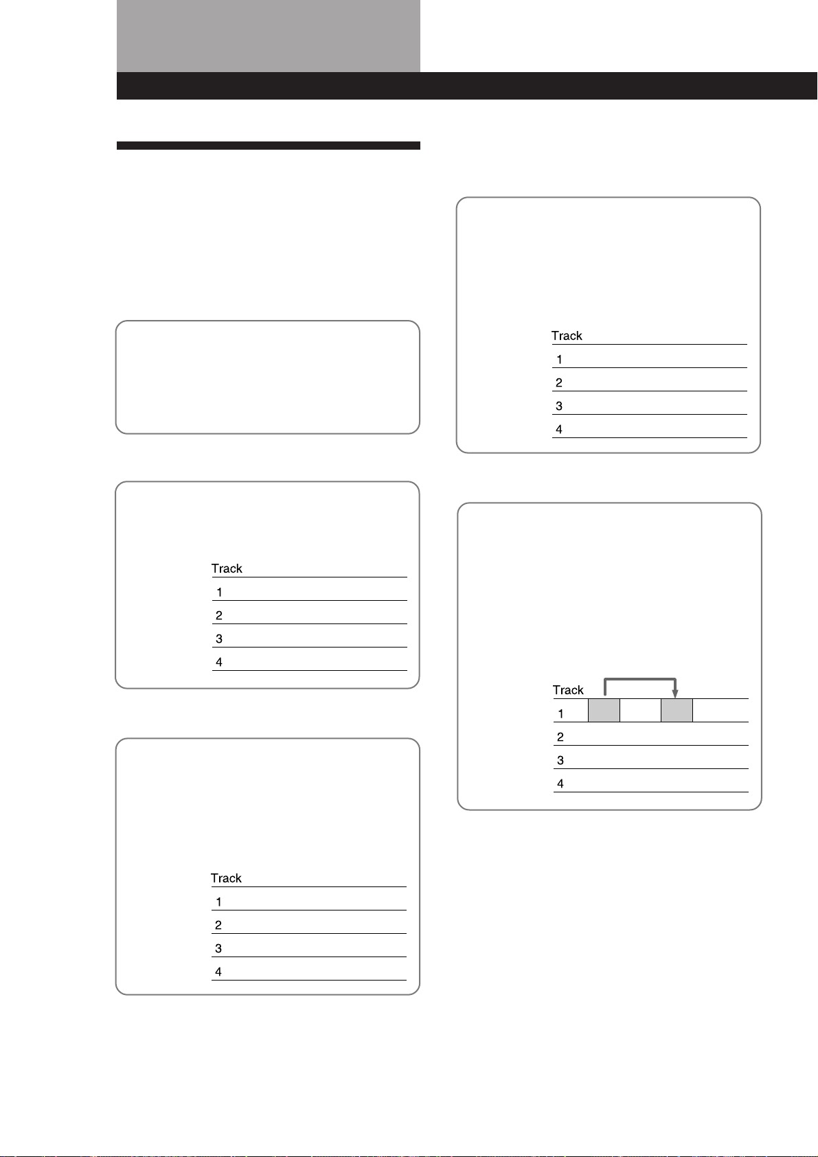
2 Record the first track.
Example : Record the drums to track 1.
See “Initial Recording” (page 19) for details.
µ
4 You want to add a harmony chorus,
but there’s no more tracks left!
No problem! If you've already used all 4 tracks,
you can record on top of a previously recorded
track.
See “Mix Write Recording” (page 27) for details.
Drums
Bass
Guitar
Vocal N Chorus
µ
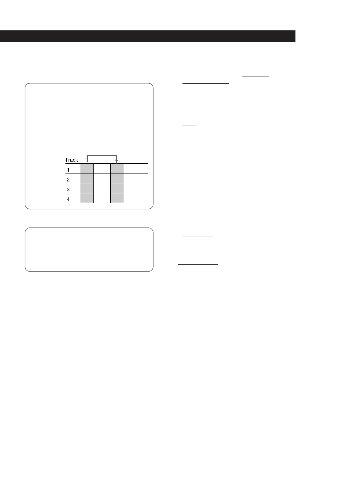
5 You realize that a certain drum fill
would sound better in a different
place.
Drums n
µ
3 Record another instrument on a
different track while listening to the
previously recorded track.
Example: Record the bass to track 2, the guitar
to track 3 and the vocals on track 4.
See “Overdub Recording” (page 20) for details.
Drums
Bass n
Guitar n
Vocal n
You can move, copy, or delete part of the song.
For example, if the first and second chorus were
reversed, they can easily be switched.
See “Editing Part of a Song (Track Edit)” (page
31) for details.
EN
4
Page 5
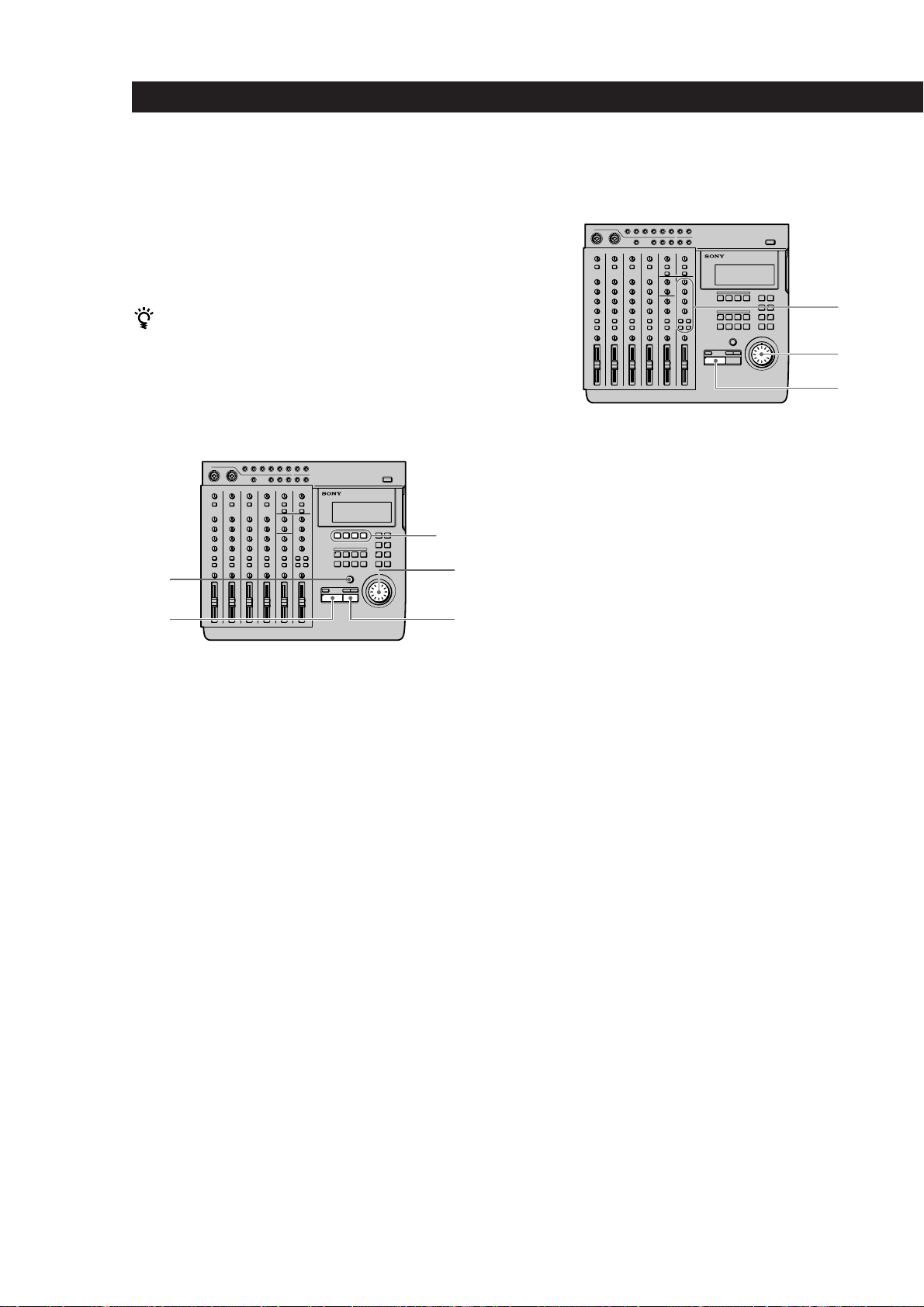
Overview of MDM-X4
Other convenient functions
µ
6 You decide you want to change the
structure of the song.
The edit functions let you add (or remove) an
extra chorus or repeat the introduction in the
middle of the song (etc.) without having to
rerecord.
See “Changing the Construction of a Song
(Section Edit)” (page 38) for details.
µ
7 Dub the tracks onto an external MD or
DAT deck while using the mixer to
adjust the balance.
See “Mixdown” (page 57) for details.
• Equipped with an easy to use Jog/Shuttle dial.
Auto Punch-In/Out function lets you rerecord
• The
part of a song by enabling the record mode
automatically only during the part which you have
specified.
See “Auto Punch-In/Out Recording” (page 22) for
details.
• The
Undo function lets you revert to the previous
state when an edit operation doesn’t produce the
desired effect.
•
Synchronization with other MIDI equipment is also
possible. In addition to the ability to synchronize this
unit with an external sequencer at start-up, you can
also remote control this unit from the sequencer
(with MMC compatible equipment only).
The synchronization functions also let you make
recordings by using a computer or sequencer to
mediate sounds from acoustic instruments, like
vocals or guitar, recorded on this unit with sounds
from other MIDI equipment and sound modules
(etc.).
See “Synchronization with MIDI Equipment” (page
52) for details.
• The
Pitch Control function enables precise speed
control.
See the “SYSTEM key” explanation in “Names and
Functions of Parts” (page 9) for details.
•A
10 INPUT/4 BUS analog mixer with exceptional
sound quality.
µ
Done !
EN
5
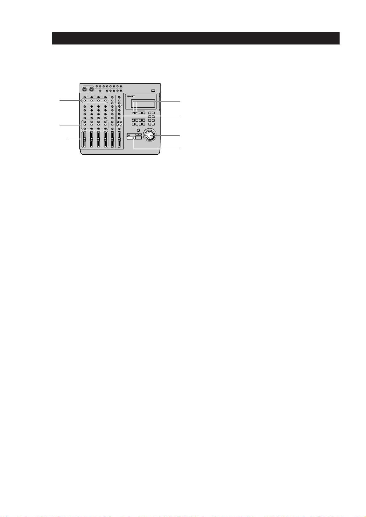
Page 6
Names and Functions of Parts
(dB)
15.0
10.0
5.0
0
–5.0
–10.0
–15.0
–20.0
20.0
20k (Hz)10k1k10020
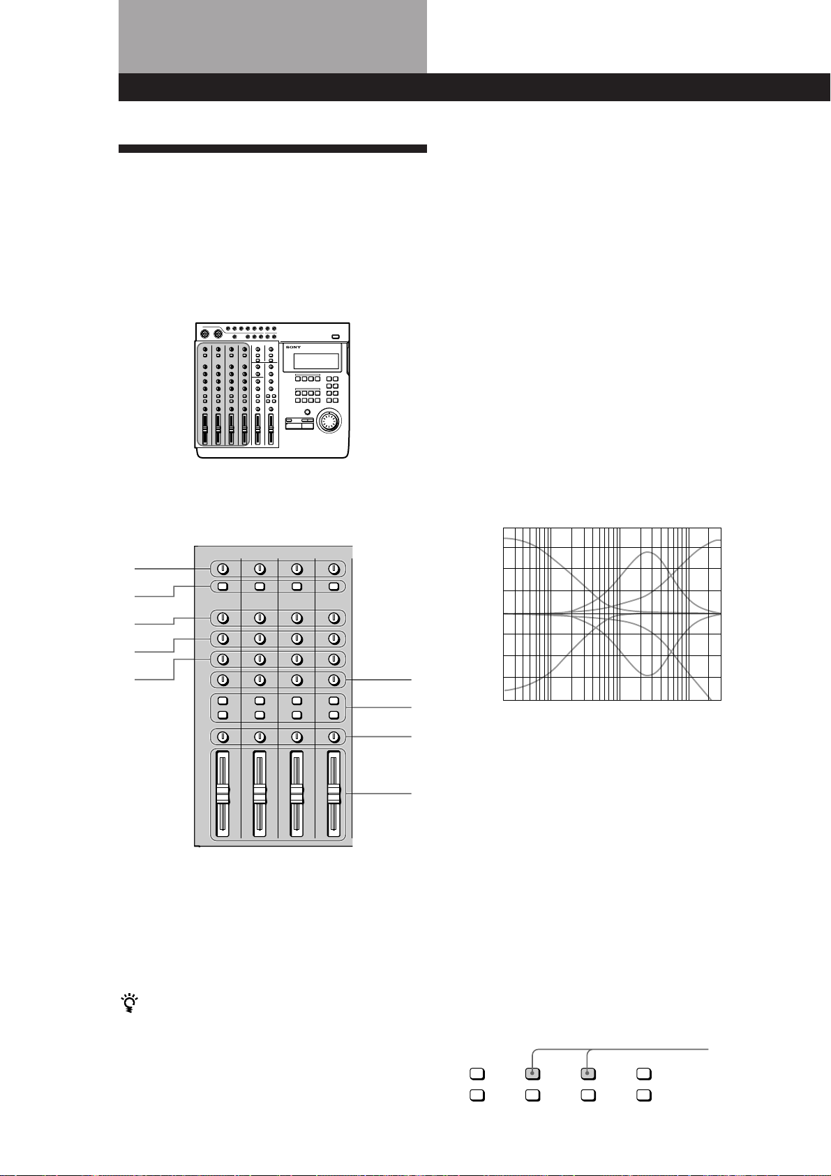
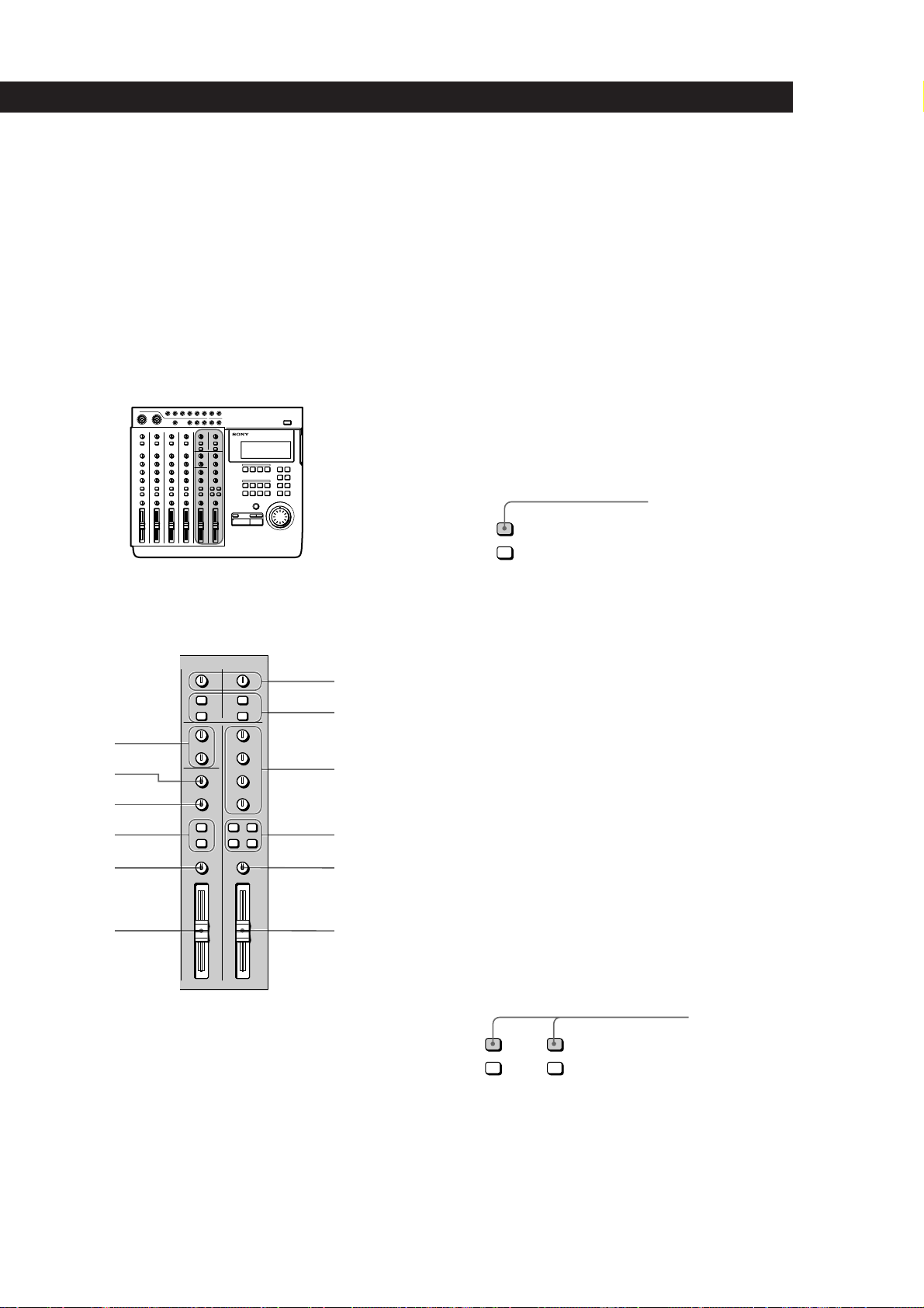
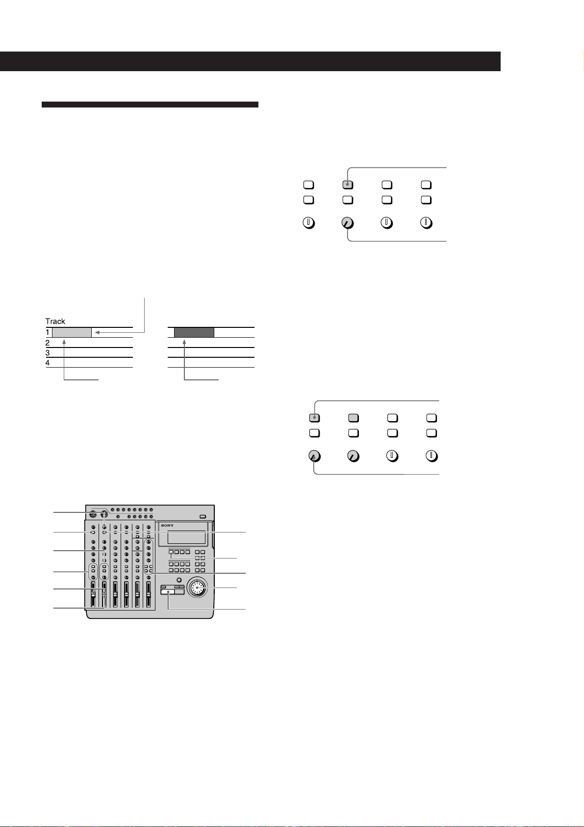
The Mixer
Also refer to the “Block Diagram” on page 64.
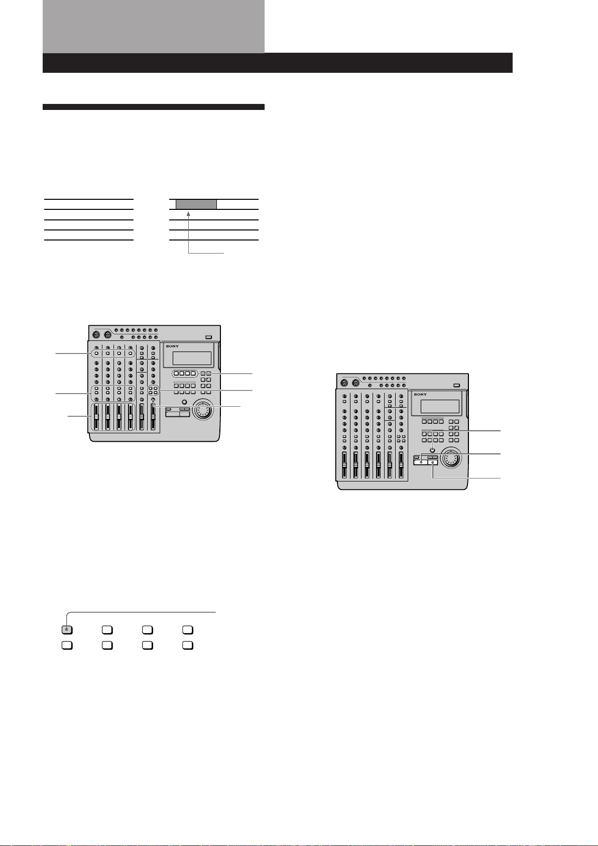
The Channel 1~4 Section
The functions described are the same for each channel
(1~4).
2 INPUT selector keys
Allow you to select either LINE/MIC (sound from the
INPUT CH jacks) or TRACK 1~4 (sound from the
recorder) for input to mixer channels 1~4.
LINE/MIC : Use to input external sounds from an
instrument or microphone (etc.).
TRACK 1~4 : Use to input sounds played back from
the recorder.
3 HIGH knobs
Adjust the treble of the respective channel. Provide a
shelving type equalization.
4 MID knobs
Adjust the middle frequencies of the respective
channel. Provide a peak type equalization.
5 LOW knobs
Adjust the bass of the respective channel. Provide a
shelving type equalization.
HIGH/MID/LOW equalizer
.
characteristic curves
1
2
3
4
5
6
7
8
9
1 TRIM knobs
Allow you to adjust the level of the signals input into
the INPUT CH1~CH4 jacks approximately 40 dB. Turn
to the right to increase the input level.
Normally, if you connect an instrument, turn to LINE;
if you connect a microphone, turn to MIC.
For the best sound characteristics, adjust the TRIM knob
so that the proper level is obtained when the fader is set
between 7 and 8.
EN
6
6 AUX knobs
Adjust the level of the sound sent to the AUX bus (1~2)
from the respective channel. Turn to “1” to output the
sound from the respective channel to AUX bus 1. Turn
to “2” to output the sound from the respective channel
to AUX bus 2.
When set to the center position, no sound is output
from either AUX bus.
7 ASSIGN keys
Determine which group bus the channels will be
assigned to (which track on the recorder they will be
recorded to).
The channel signal is always connected to the stereo
bus
Example: To assign the sounds from channels 2 and 3
to group bus 1. (To record them to track 1 of
the recorder).
Press down
ASSIGN ASSIGN ASSIGN ASSIGN
1 2 1 2 1 2 1 2
3 43 43 43 4
Page 7
Names and Functions of Parts
8 PAN knobs
Adjust the sound balance of the stereo or group bus.
Turn towards␣ “L” to move the sounds toward group
bus 1 or 3 and the “L” side of the stereo bus. Turn
towards “R” to move the sounds toward group bus 2
or 4 and the “R” side of the stereo bus.
9 Faders 1~4
Adjust the volume of each channel.
Channel 5,6 and MASTER
.
3 LOW knob
Adjusts the bass of the sound input to the INPUT 5/6
jacks at the top of the unit. Provides a shelving type
equalization.
4 ASSIGN keys
Determines which group bus the sounds input to the
INPUT 5/6 jacks at the top of the unit will be assigned
to (which track on the recorder they will be recorded
to).
Channel 5 can only be assigned to group bus 1 or 3.
Channel 6 can only be assigned to group bus 2 or 4.
EXAMPLE: To assign the sounds from channels 5 and 6
to group bus 1 and 2 respectively. (To
record them to track 1 and 2 of the
recorder).
ASSIGN
1 2
3 4
5 BALANCE knob
Adjusts the relative balance of channels 5 and 6.
Rotate toward “L” to increase the volume of channel 5.
Rotate toward “R” to increase the volume of channel 6.
Press down
7
8
1
2
9
3
4
5
6
1 MASTER AUX 1~2 knobs
Adjust the master level of the AUX bus sound output
from the AUX OUTPUT 1~2 jacks.
2 HIGH knob
Adjusts the treble of the sound input to the INPUT 5/6
jacks at the top of the unit. Provides a shelving type
equalization.
0
!¡
!™
6 Fader 5/6
Simultaneously adjusts the volume of both channels 5
and 6.
7 RETURN knobs (1 and 2)
Adjust the volume of the sound input into the
RETURN 1 and 2 jacks at the top of the unit. (Return
sound is generally used for adding external effects.)
8 ASSIGN keys
Determine which group bus (1~4) the return sounds
will be assigned to (which track on the recorder they
will be recorded to).
Example: To assign the sounds from return 1 and 2 to
group bus 1 and 2. (To record them to tracks
1 and 2 on the recorder).
Press down
ASSIGN ASSIGN
1 2 1 2
3 43 4
(continued)
EN
7
Page 8
Names and Functions of Parts
9 TRACK 1~4 knobs
Use to adjust the overall sound balance when
monitoring playback from the recorder (CUE monitor)
by turning the knob for each track as desired. When
using the CUE monitor function, be sure to press down
the monitor track setting CUE key (0 below).
0 Monitor Track Setting keys
Select the sound to be monitored.
1–2 : Press down to monitor the sound from group bus
1 and 2.
3–4 : Press down to monitor the sound from group bus
3 and 4.
CUE : Press down to monitor playback from the
recorder. Use the TRACK 1~4 knobs to adjust
volume of the individual tracks.
STEREO : Press down to monitor the sound from the
stereo bus.
!¡ MONITOR knob
Adjusts the volume of the sound output from the
MONITOR OUT jacks (on the rear panel) and the
HEADPHONES jack (on the front panel).
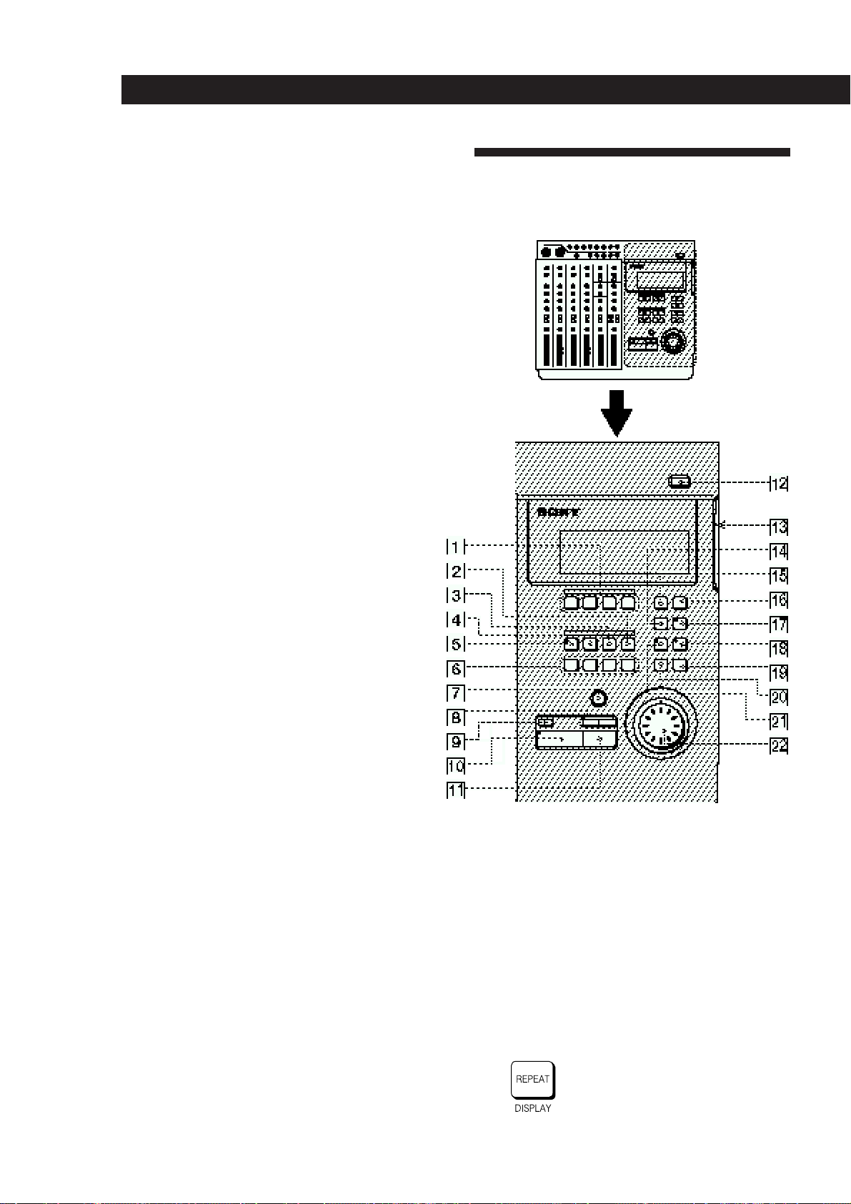
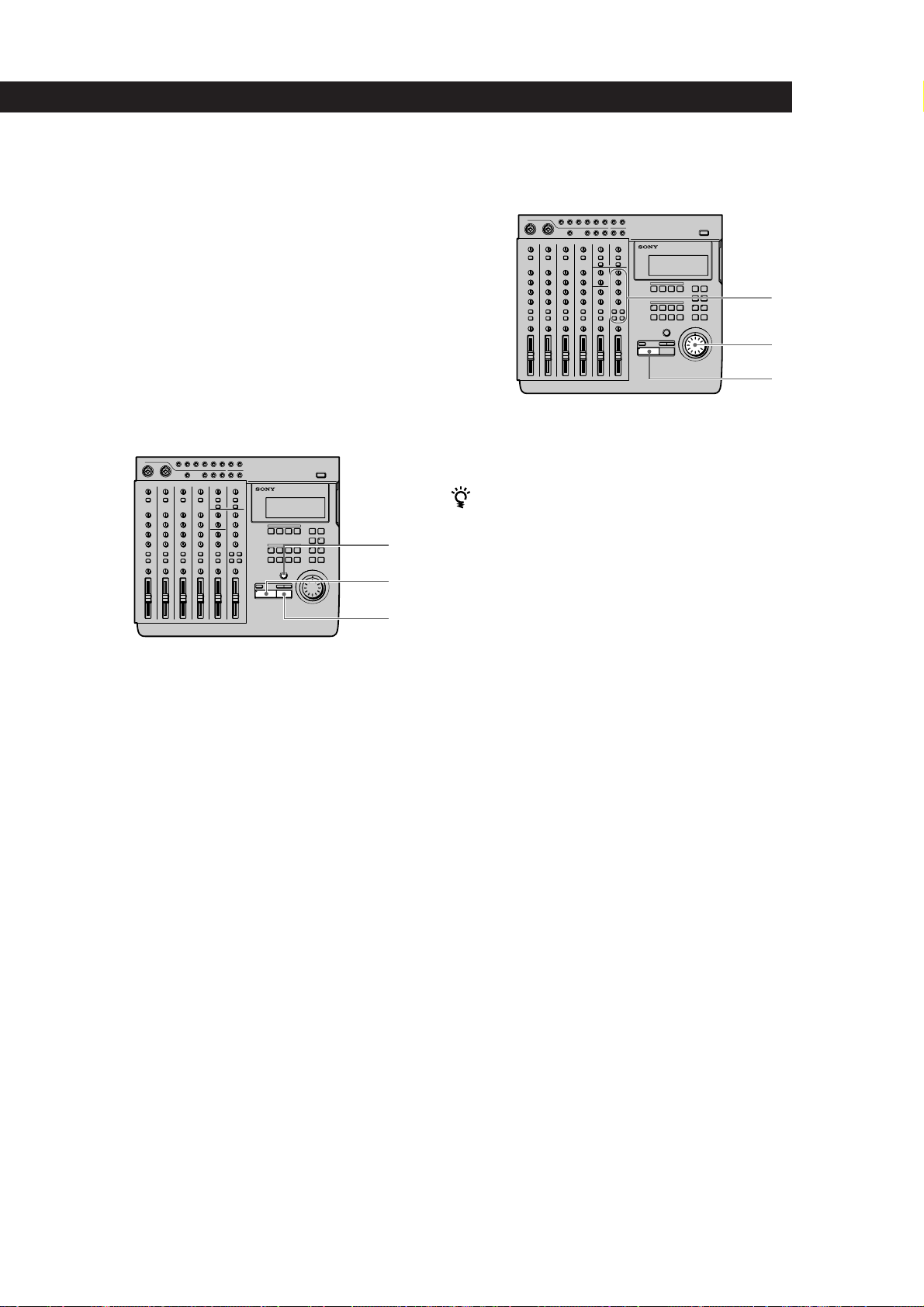
The Recorder
Control Panel
!™ MASTER fader
Adjusts the volume of the stereo bus sound output
from the STEREO OUT jacks on the rear panel.
1 REC SELECT 1~4 keys
Press to light the corresponding track indicator(s) and
select the track(s) to be recorded. These keys also
function as in/out keys during manual punch-in/out
recording.
2 SHIFT key
Holding down this key when you press another key
lets you carry out the function written below the
respective key.
EXAMPLE: The REPEAT key
• When pressed alone, it
functions as the REPEAT key
• When pressed while holding
EN
8
down SHIFT, it functions as
the DISPLAY key.
Page 9

Names and Functions of Parts
3 OUT key
Sets the out point (edit end point).
4 IN/DEST key
Sets the in point (edit start point).
Press while holding down SHIFT to set the destination
point (edit destination point).
5 MARK key
Press to set a mark point (and the key starts blinking).
Press IN, OUT, DEST, or A~H while the MARK key is
blinking to set the mark point to the respective key.
This unit lets you assign up to 11 mark points using IN,
OUT, DEST, and A~H.
6 Locate point keys
Press to recall mark points. To specify points E~H,
press the respective key while holding down SHIFT.
7 REC key
Press to enter record mode. The key blinks, to indicate
record pause mode. The key lights steadily when
recording.
8 =/+ keys
Press to locate the beginning of the previous or next
song. When adjusting a mark point, they can also be
used with the rehearsal function to switch between a
volume increase or decrease after the mark point.
9 TOP key
Press once to locate the beginning of the first song on
the disc. Press again during stop mode to locate the
beginning of the unrecorded (blank) part of the disc.
0 ( PLAY key
Starts playback. Lights during playback.
!¡ p STOP key
Stops recording or playback.
Hold down this key and press the ( PLAY key to
activate the IN-OUT playback mode and play back the
section between the IN and OUT points repeatedly.
Pressing this key during stop mode to write the TOC
data* to the disc.
!¢ REPEAT/DISPLAY key
Press to activate the repeat playback mode. The repeat
mode changes as follows each time you press the key:
• REPEAT : Repeats all the songs on the disc.
• REPEAT 1 : Repeats the current song.
• 1 : Plays the current song once. After playback, the
unit locates the beginning of the song.
• (no indicator) : Off. Plays all of the songs on the disc.
Press while holding down SHIFT to change the display
mode as follows:
• Time Mode : Shows the counter display in time.
• Bar Mode : Shows the counter display in bars.
• Remaining Mode : Shows the amount time which
can be recorded remaining on the disc.
Note
Numbers will not be displayed in bar mode, if no tempo
information is input.
!∞ EDIT key
Press to enter Edit mode. Edit mode can only be
entered when the disc is in stop mode.
!§ SYSTEM key
This key has two functions.
• System setting
Press when making system settings to enter the
system settings. See “Changing a Setting” (page 18)
for details.
• Pitch Control
Press while holding down SHIFT to turn the
recording/playback pitch control “on”. Press again
while holding down SHIFT to turn the recording/
playback pitch control “off”.
Pitch control “on” : Recording or playback is
conducted in the preset pitch. (“Vari Pitch” is
displayed.)
Pitch control “off” : Recording or playback is
conducted in the normal pitch. (“Fixed Pitch” is
displayed.)
See “System Settings” (page 17) for details on the
pitch setting.
(continued)
!™ § EJECT key
Press to remove the disc.
If the TOC data* has not been written to the disc, it will
be written automatically before the disc is ejected.
* You must write the TOC data to disc after a
SECTION edit, SONG edit, or DISC edit. See pages
38 and 44 for details.
!£ Disc insertion slot
Insert the disc into this slot.
EN
9
Page 10
Names and Functions of Parts
!¶ RHSL (Rehearsal) key
This key has two functions:
• Record rehearsal (rehearsal function)
Press during record pause mode to cause the
indicator to blink and set this unit to operate as if it
were recording, without actually recording. This is
called rehearsal mode. (Rehearsal mode can also be
activated by pressing RHSL when the AUTO
PUNCH key is lit.)
During record rehearsal, all other operations will
function as if the unit was recording. This provides a
convenient way to practice without actually
recording.
Press p STOP to cancel the rehearsal mode.
Rehearsal mode, however, is not activated when
recording a new song.
• Locate point adjustment (locate adjust function)
Press to light the indicator and repeat the section just
before and after the current locate point. The repeat
time is specified in the roll time setting. Turning the
JOG dial during rehearsal lets you adjust the position
of the locate point.
Press p STOP to cancel the locate adjust mode.
See “Correcting the position of the locate point”
(page 32) for details.
Note
During locate adjust mode the counter value does not
change to reflect the position of the playback sound.
Use JOG or SHUTTLE to adjust the counter value/position
of the respective locate point. However, if you do not
register the new value as a mark point it will be erased after
the adjustment.
!• UNDO key
Erases the previous edit or auto punch-in/out
operation and returns the data to its original status.
See “Using the Undo Function” (pages 24, 31, 38, 43)
for details.
!ª ENTER key
Press to carry out the selected operation (etc.).
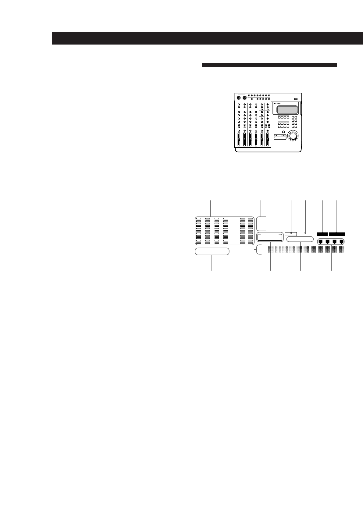
The Display
.
1 2 3
CLIP
– 3
– 6
–12
–20
–30
1R2R3R4 L
R
–40
(dB)
000
MIDI-CLK MTC
R
SONG
STEREO NO.
SYNC-OUT MMC REPEAT
7 98 !¡0
1 Level meters
• 1~4
During playback : Display the output levels of each
track on the disc.
During recording : Display the input levels of the
track(s) being recorded.
During stop mode or when no disc is inserted :
Displays the volume of group bus 1~4.
• L, R
Displays the volume of the stereo bus.
4 5 6
BAR
MIN
00
IN/OUT PLAY
BEAT
SEC
00
EDIT SYSTEM
1
1 2 3 4
CLK
FRM
10
EN
@º EXIT key
Press to cancel the selected operation or to exit the edit
mode.
@¡ AUTO PUNCH key
Use to select the auto punch-in/out function.
@™ Jog dial (Jog/Shuttle dial)
Use to search (find a specific point within a song),
select items from menus, set parameters, and adjust
locate point positions (etc.).
The smallest increment in which a locate point can be
adjusted is one click of the jog dial (approx. 11.6 msec).
2 Counter display
Displays the time (minute/second/frame) or bar (bar/
beat/clock).
3 MMC indicator
Lights when the unit can receive MMC (MIDI Machine
Control) signals.
4 REPEAT indicator
Light during repeat playback.
“REPEAT” lights when repeating all the songs on the
disc, “REPEAT1” lights when repeating one song.
Page 11
5 [EDIT] indicator
Lights during edit operations (track, section, song,
disc).
Names and Functions of Parts
Input and Output Jacks
6 [SYSTEM] indicator
Lights during system setting operations.
7 R indicators
Lights to indicate that the respective track was selected
for recording using the REC SELECT keys. The track
number corresponds to the group bus number.
8 Title display area
Displays the song or disc title, as well as edit menu
information.
9 SYNC-OUT indicator
Displays the currently selected output synchronization.
See pages 17 and 52~56 for details.
MIDI–CLK : Lights when the MIDI clock is being
output.
MTC : Lights when the MIDI time code is being
output.
0 IN/OUT PLAY indicator
Lights during IN/OUT playback.
!¡ Track display indicator
Displays the source track during editing.
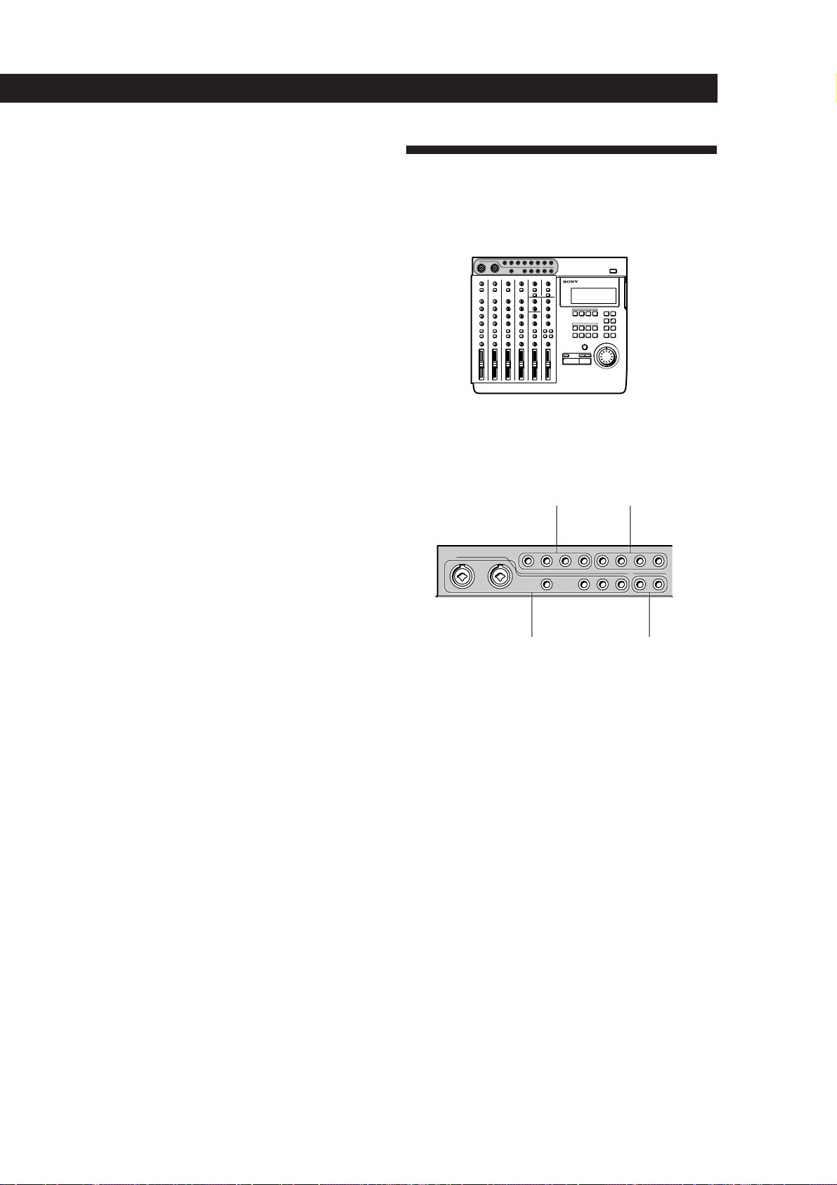
Top panel
.
1 2
43
1 TRACK 1~4 output jacks
Output the sound from tracks 1~4 of the recorder.
The TRACK 1~4 jacks output the signals for each track
as they were recorded onto the disc.
Previously recorded signals are played back and
output, even when the recorder is recording.
2 RETURN 1 / 2 (L (MONO) /R) input jacks
Use to input signals from external sources.
For example, when sending a sound modified by an
external effect back to the mixer.
Use the L (MONO) jack when inputting monaural
signals.
3 CH 1~6 input jacks
Use to input sounds to channels 1~6. The CH 1~4 jacks
are for signals from microphones or line level sources.
The CH 5 and 6 jacks are for line level signals only.
Channel 1 and 2 allow direct connection of XLR type
plugs. (Channels 1 and 2 are balanced inputs for both
XLR and standard plugs.)
(continued)
11
EN
Page 12
Names and Functions of Parts
4 OUTPUT AUX 1/2 jacks
Output sound for use as the send output. After adding
an outboard effect to the sound output from these
jacks, use the RETURN 1/2 (L/R) jacks to input it back
to this unit.
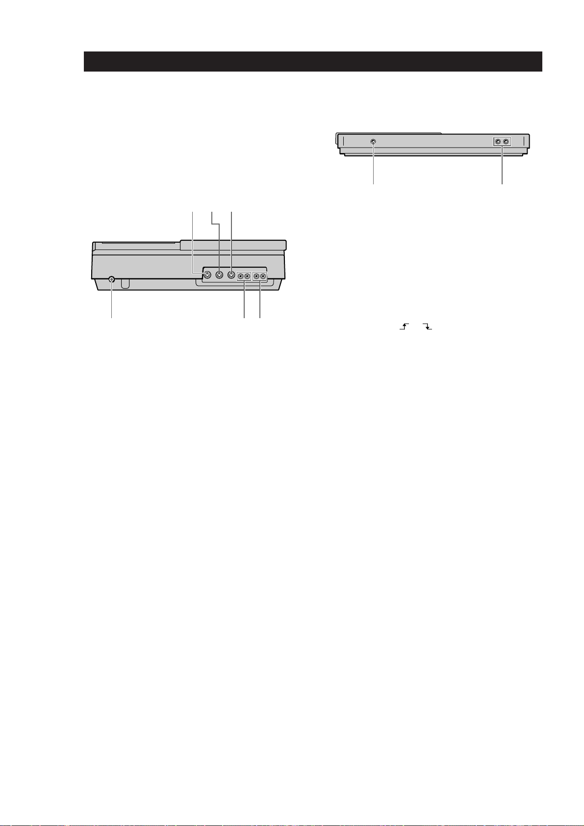
Rear Panel
3
21
54 6
1 MIDI THRU jack
Outputs the same signal input to the MIDI IN jack.
2 MIDI OUT jack
Outputs the MIDI signal. Connect to the MIDI IN jack
of another piece of MIDI equipment.
Front Panel
1 2
1 HEADPHONES jack
Connect a pair of headphones with a standard type
plug.
2 ASSIGN SW 1,2 jack
For connecting external switches, such as a foot switch
(etc.).
See “System Settings” (page 17) for details regarding
the functions which can be controlled.
You can use either
the power is turned on, this unit registers the current
position of the connected pedal as “OFF”.
or type foot switches. When
3 MIDI IN jack
Inputs the signals output from the MIDI OUT jack of
another piece of MIDI equipment.
4 Power switch
Use to turn the power of this unit on and off.
5 MONITOR OUT jack
Outputs the sound of the monitor bus. Connect to a
pair of monitor speakers or an amplifier.
See “Connections for Recording” (page 13) for details.
6 STEREO OUT jack
Outputs the sound of the stereo bus. Connect to a DAT
deck (etc.) during mixdown.
See “Connections for Recording” (page 13) for details.
12
EN
Page 13
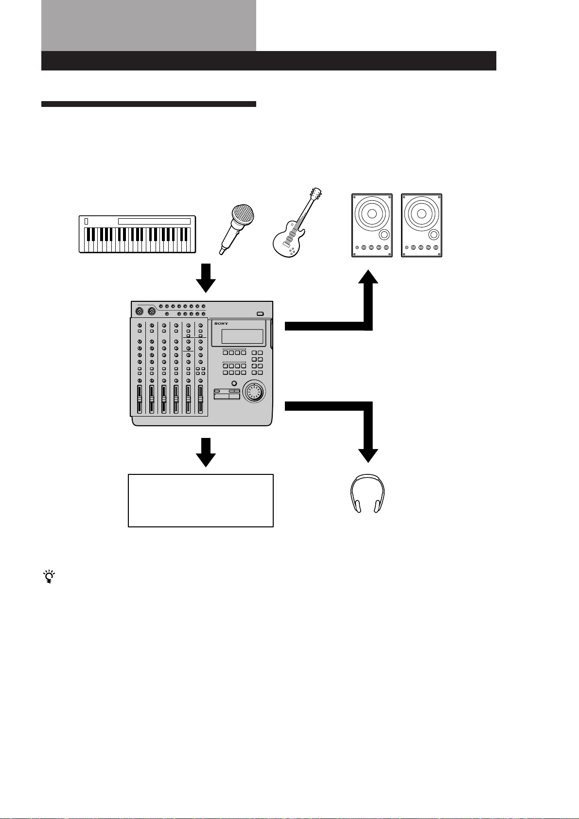
Connections and Signal Flow
Connections for Recording
Connect instruments, microphones, and amp and
headphones for monitoring as shown below.
Instruments or microphones
To INPUT CH1~CH 6 jacks
(You can use XLR type plugs
with CH-1 and CH-2)
From the STEREO OUT jacks
on the rear panel of this unit
External amplifier and speakers
From the MONITOR OUT jacks
on the rear panel of this unit
From the HEADPHONES jacks
on the front panel of this unit
Recording equipment for use in
mixdown
• DAT recorder
• MD recorder
When inputting sound from a sound module into this
unit
You can mix the sound with sounds previously
recorded on tracks 1~4 by using the INPUT CH-5 or
INPUT CH-6 jacks.
Do the following when connecting an external effector
to input the return sound.
To output sound to the effector : Use the AUX 1 or
AUX 2 jacks on the top panel of this unit.
To input sound from the effector (return sound) : Use
the RETURN 1 or RETURN 2 jacks on the top panel
of this unit.
Headphones for monitoring
Turning on the Power
After you have completed all connections, connect the
power cord from this unit to a wall outlet.
13
EN
Page 14
Connections and Signal Flow
Connecting MIDI Equipment
Connect MIDI equipment as shown in the following
diagram.
For details regarding connections for synchronized
operation with a sequencer (etc.), see “Synchronization
with MIDI Equipment” (pages 52~56).
Sequencer (etc.)
MIDI IN jack MIDI OUT jack
MIDI OUT jack
To output the MIDI
signal input to this unit’s
MIDI IN jack directly to
other MIDI equipment.
External sound module (etc.)
MIDI IN jack
MIDI THRU jack
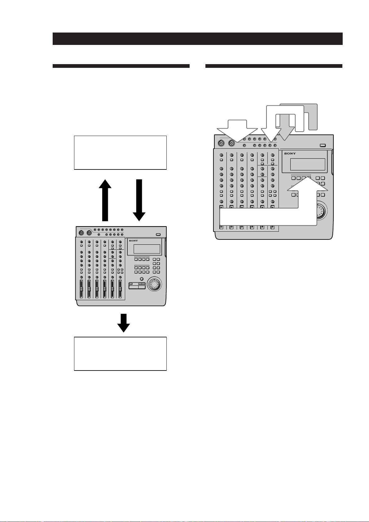
MDM-X4 Signal Flow Diagram
The following diagram shows the internal signal flow
of this unit.
4
1
1 Input external sounds.
2 The input sound is recorded after being mixed and
assigned to the respective group bus (1~4).
3 The playback sound from the recorder is input
back into the mixer (mix write recording, bounce
recording).
4 The playback sound from the recorder is output to
an external component, that adds an effect,
before being input back into the mixer (mix write
recording, bounce recording).
This unit’s 6 channel inputs and 2 stereo return inputs
are connected to group bus 1~4 and stereo bus L/R.
(For group bus 1~4 use the ASSIGN keys to assign the
input sound to a group bus. The channel signals are
always connected to the stereo bus. In cases where you
do not want to mix the signals to the stereo bus, lower
the faders for the respective channels to “0”.)
When monitoring, you can select group bus 1-2, group
bus 3-4, stereo bus, or TRACK 1~4 OUTPUT (CUE
bus).
For details on how to monitor, see “Monitoring
Example” (page 15).
3
2
14
EN
Page 15
Monitoring
Monitoring Preparations
This unit enables you to monitor the following 4 types
of signals as necessary.
1 Group 1, 2 : Select to monitor mixer group bus 1 and
2. The sound from group bus 1 is localized in the L
(left) channel and the sound from group bus 2 is
localized in the R (right) channel. When recording,
select to monitor the sound being recorded.
2 Group 3, 4 : Select to monitor mixer group bus 3 and
4. The sound from group bus 3 is localized in the L
(left) channel and the sound from group bus 4 is
localized in the R (right) channel. When recording,
select to monitor the sound being recorded.
3 CUE : Select to listen to all the sound recorded on
the disc. You can adjust the volume level of the
individual tracks using the TRACK 1~4 knobs
located above the MONITOR keys. (All tracks are
heard in mono.) When recording, the track being
recorded is muted.
4 STEREO : Select to listen to the sound of the mixer’s
stereo bus. For use during mixdown (etc.).
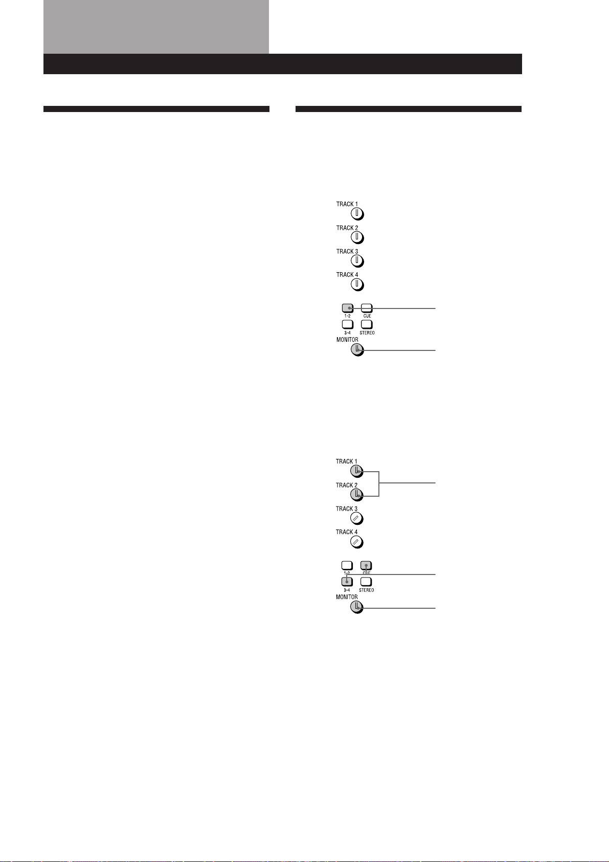
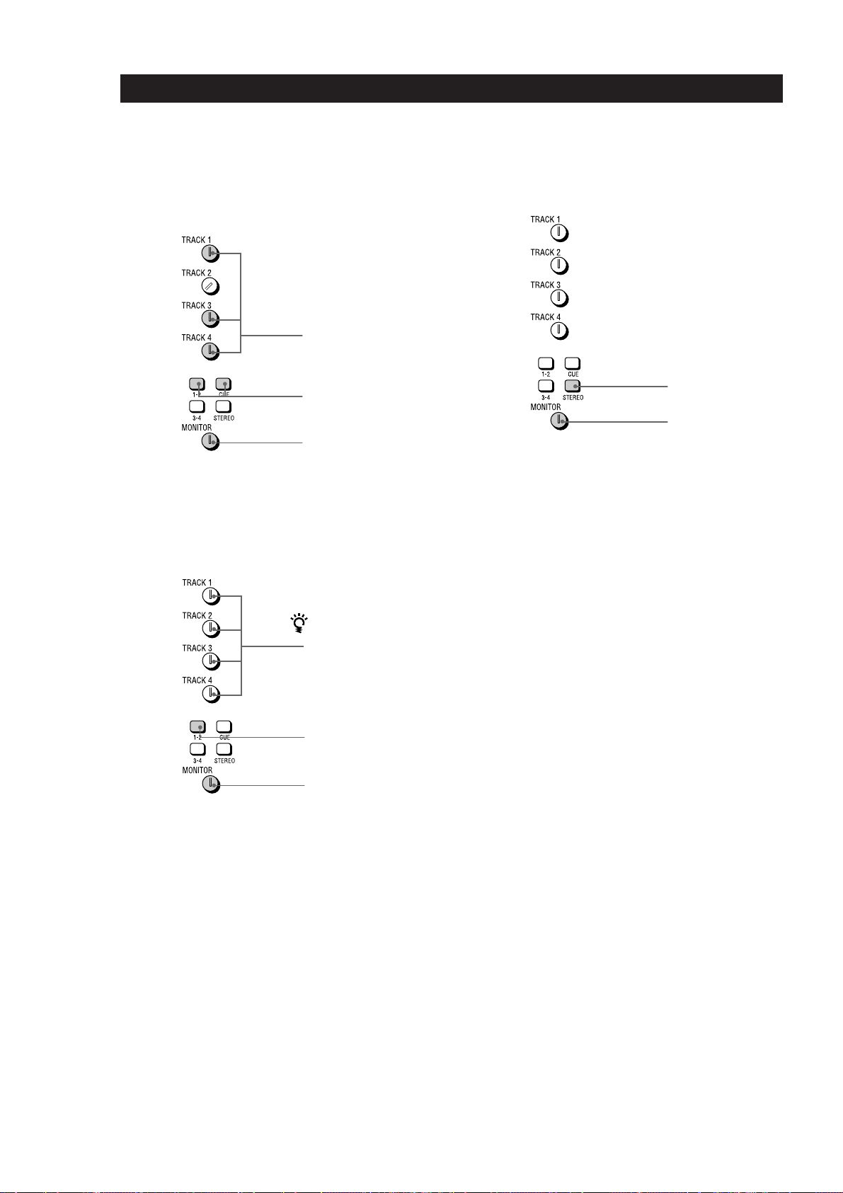
Monitoring Example
EXAMPLE 1: Monitoring the sound from
group bus 1 and 2 (during recording, etc.)
Press down
Turn to adjust level
EXAMPLE 2: Monitoring the sound being
recorded to tracks 3 and 4 while
monitoring the sound of tracks 1 and 2
(during overdubbing, etc.)
Turn to adjust level
Press down
Turn to adjust level
(continued)
15
EN
Page 16
Monitoring
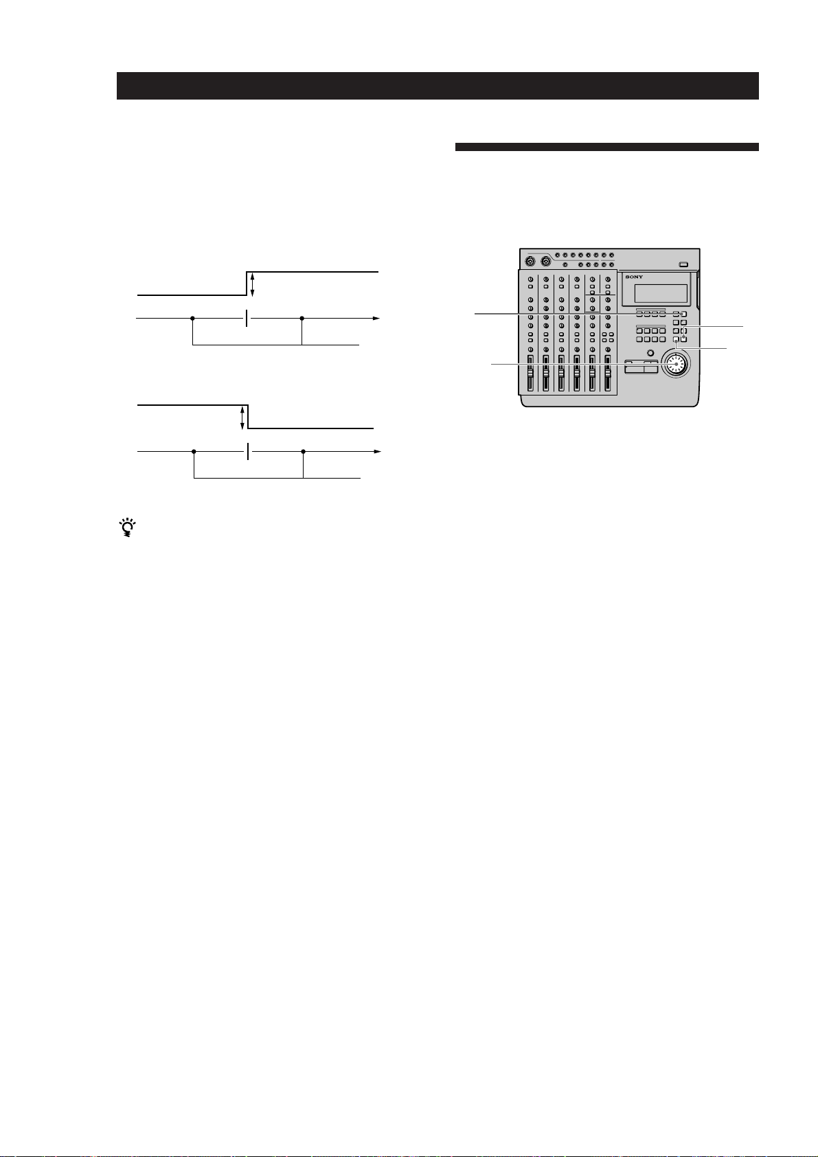
EXAMPLE 3: Rerecording part of track 1
while monitoring the sound of tracks 3
and 4 (during punch-in/out recording,
etc.)
Turn to adjust level
Press down
Turn to adjust level
EXAMPLE 4: Mixing tracks 1~4 for
recording onto tracks 1 and 2 (during mix
write recording, etc.)
EXAMPLE 5: Monitoring the sound of the
stereo bus (for mixdown, etc.)
Press down
Turn to adjust level
You do not need to use
the CUE monitor
This operation uses the
mixer for mixing.
Press down
Turn to adjust level
16
EN
Page 17

Setting Up the Operating Environment
System Settings
You customize the operating environment by turning
the MIDI synchronization and UNDO (undo last
operation) functions (etc.) on or off.
Pitch setting (Pitch)
You can set the pitch in 0.25% increments within a
range of ±8%. When you turn the pitch control on after
setting the pitch , recording/playback is conducted at
the selected pitch.
See the “System key” in “Names and Functions of
Parts” (page 9) for details on turning the pitch control
on/off.
MMC setting (MMC)
This sets the MMC (MIDI Machine Control) reception.
See page 55 for details about MMC.
off : No reception. Use this setting when using this unit
by itself.
on : The unit operates according to the received MMC
signals.
Device ID setting (Dev ID)
Sets the MMC ID number. It can be set to any number
between 0 and 126. When this unit receives ID = 127
signals, they are registered as a valid signals regardless
of this unit’s ID setting.
Synchronized output source setting (Sync)
Sets the Synchronized output source. See pages 52 and
53 for details about synchronization.
off : Does not output a synchronization signal
MTC (MIDI Time Code) : When using the MTC for
synchronization.
MCLK (MIDI Clock) : When using the MIDI clock for
synchronization.
MTC frame number setting (Frame)
Sets the MTC frame number (per second). You can
select either 25 or 30 non-drop frames.
Assignable switch 1, 2 setting (Sw-1, Sw-2)
Allows you to assign one of the following commands
for control by the external switch connected to the
ASSIGN SW1 or SW2 jack on the front panel.
Play : Same function as this unit’s ( PLAY key.
RecIO : Press once for the same function as the REC
key (punch-in). Press again for the same function as
the ( PLAY key (punch-out). This setting allows
you to conduct punch in-out recording from an
external switch.
Stop : Stops the disc operation.
IOply (In-Out Play) : Starts IN-OUT playback
PlayS (Play-Stop) : Press one to start playback, press
again to stop playback.
Rec S (Rec-Stop) : Press once to start recording, press
again to stop recording.
Pre-roll/Post-roll setting (Roll)
Allows you to set the pre-roll/post-roll time used
during rehearsal (locate point adjustment) and auto
punch-in/out operations in 1 second increments. It is
adjustable from 1 to 10 seconds.
Undo function on/off setting (Undo)
This determines whether the undo function will be on
or off when you use auto punch-in/out. During edit
mode, however, the undo function is always on.
Changing this setting also changes the redo function
(that allows you to undo the undo) setting is also
changed at the same time.
Disabl (off) : Turns off the undo function
Enabl (on) : Turns on the undo function
The indicator on the UNDO key has the following
meanings:
GREEN : You can use the undo function.
(blinking) : Preparing to carry out the undo
function.
RED : Undo (or Redo) has been carried out.
(off) : You cannot use the undo function (such as
when the previous operation cannot be undone
(etc.)).
See page 24 for details about using the undo function
with the auto punch-in/out function.
Note
Do to the limitations of this system, if the blank space on
the disc becomes too small it may not be possible to use
the undo function even if it is set to “on”. In this case, the
indicator on the UNDO key will be off. Be sure to check
whether this indicator is on or off before performing an
edit operations.
Recordable track number setting (Rec)
This sets the number of tracks to be used on the disc.
The number of tracks selected is effective the next time
a song is recorded. During playback, the number of
tracks is selected automatically according to the source
disc.
The selectable tracks also differ depending on the type
of disc you use (MD DATA or music MD).
Rec Mode
4
2
1
Usable
tracks
1~4
1, 2
1
Recording
time
37 min.
74 min.
148 min.
Usable
Discs
MD DATA
MD DATA,
Music MD
MD DATA,
Music MD
Note
The Rec Mode automatically switches to 2 track for music
MDs (even if it was previously set to the 4 track mode).
After recording on a music MD, be sure to reset the Rec
Mode to 4 track when you want to make a 4 track recording
using a MD DATA disc.
(continued)
17
EN
Page 18
Setting Up the Operating Environment
Rehearsal mode setting (RHSL)
This setting lets you determine whether the volume
will increase or decrease after the locate point when
adjusting the position of a locate point with the
rehearsal function. See page 32 for details about locate
point adjustment.
Â: the volume increases past the locate point.
Volume increases
Changing a Setting
Use the following operations to change the system
settings
Locate point
µ: the volume decreases past the locate point.
Volume decreases
Locate point
During rehearsal mode, press the = or + key to
switch between increased or decreased volume after the
locate point.
Display brightness setting (Dimmer)
Adjusts the display brightness. You can choose from 8
levels (1~8). Larger numbers provide a brighter
display.
Rehearsal
period
Rehearsal
period
1
3
5,6
2,4
1 Press SYSTEM.
[SYSTEM] appears in the display.
2 Turn the jog dial to display the item you want to
adjust.
The item blinks in the display.
3 Press ENTER.
The blinking moves to the right of the item.
4 Turn the jog dial to display the setting you desire.
5 Press EXIT.
The item starts blinking again.
6 Press EXIT again.
[SYSTEM] disappears from the display.
18
To reset this unit to the original factory
settings
1 Turn off the power to this unit.
2 Hold down SYSTEM while turning the power
back on.
The power comes on and “Initialized” appears in
the display. The system settings are reset to the
original factory settings.
EN
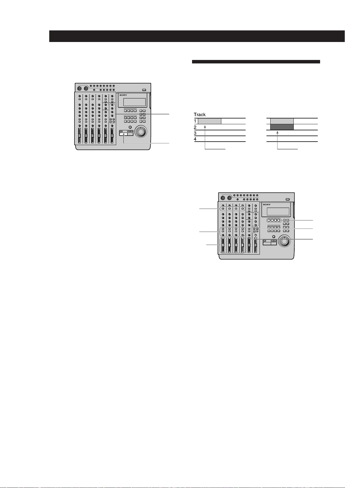
Page 19
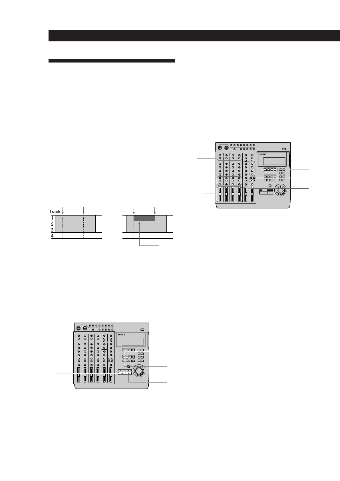
Initial Recording
RecordingRecording
6 Turn the MONITOR knob to adjust the sound to a
level which can be monitored.
This shows you how to record the very first track onto
a blank disc.
Track
1
2
3
4
b
Recorded
section
Preparations
1
3
6,8
2,7
7 Use the fader to adjust the recording level.
Play a relatively loud phrase and make
adjustments by watching the level meter for the
track you want to record.
If necessary, you can use the TRIM knob to adjust
the recording level and equalizer.
Adjust the recording level so that the CLIP
indicator does not light.
Adjust the TRIM knob so that the proper level is
obtained when the fader is set between 7 and 8 to
achieve good frequency characteristics.
8 Turn the MONITOR knob as in step 6 to adjust
monitor level.
Recording
4
5
1
Set the INPUT switch for the channel to which
1
you will input the instrument or microphone
sound to LINE/MIC (up position).
2 Set the fader for the channel to which you will
input the sound to about 7 or 8.
3 Use the ASSIGN switch and PAN knobs to direct
the sound to the group path you want to record.
EXAMPLE: To assign channel 1 to group path 1
ASSIGN ASSIGN ASSIGN ASSIGN
1 2 1 2 1 2 1 2
3 43 43 43 4
Press down
4 Press the REC SELECT key corresponding to the
group path number you selected in step 3 to
specify the track to be recorded.
5 Press the monitor track set key corresponding to
the group path number you selected in step 3.
2
3
1 Press REC.
The unit switches to record pause mode.
2 Press ( PLAY.
Recording begins
3 When you’ve finished playing, press p STOP.
This unit automatically goes to the beginning of
the recorded song.
It takes a few seconds for the unit to process the
information after pressing p STOP.
Please note that the length of the song is fixed at
the point where the initial recording ends.
Note
Do not turn off the power during recording. Not only may
you loose the data for the current song, you may loose all of
the data on the disc.
(continued)
19
EN
Page 20
Recording
6
5
2,7
3
4
1
b
Checking the Recording
Overdub Recording
You can record other sound on a different track while
listening to the playback from a previously recorded
track. This kind of recording is called overdubbing.
1
1
Press CUE to prepare for monitoring.
Adjust the monitor volume using the respective
TRACK knobs and the MONITOR knob.
2 Press ( PLAY.
Playback begins.
If necessary, you can use the jog dial to locate a
specific point.
To rerecord
Follow the “Recording” procedure on the previous
page.
2
Recorded section
Section
recorded by
overdubbing
Preparations
Set the INPUT switch for the channel to which
1
you will input the instrument or microphone
sound to LINE/MIC (up position).
2 Set the fader for the channel to which you will
input the sound to about 7 or 8.
20
EN
3 Use the ASSIGN switch and PAN knobs to direct
the sound to the group path you want to record.
4 Press the REC SELECT key corresponding to the
group path number you selected in step 3 to
specify the track to be recorded.
5 Press the monitor track set key corresponding to
the group path number you selected in step 3.
6 Press CUE, then turn the TRACK knob
corresponding to the track containing the
recorded sound you want to hear while recording
to adjust the sound to a level at which it can be
monitored.
Use the MONITOR knob to adjust the monitor
level.
Page 21
Recording
7 Use the fader to adjust the recording level.
Play a relatively loud phrase and make
adjustments by watching the level meter for the
track you want to record.
If necessary, you can use the TRIM knob to adjust
the recording level and equalizer.
Adjust the recording level so that the CLIP
indicator does not light.
Adjust the TRIM knob so that the proper level is
obtained when the fader is set between 7 and 8 to
achieve good frequency characteristics.
Recording
1
2
Checking the Recording
1
Turn the jog dial to set the counter to the point
you want to hear.
If you set it as a locate point, it can be located
immediately with the LOCATE keys.
2 Press CUE to prepare for monitoring.
Adjust the monitor volume using the respective
TRACK knobs and the MONITOR knob.
2
1
3
1 Press REC.
The unit switches to record pause mode.
2 Press ( PLAY.
Recording begins.
Play together with the previously recorded
performance.
3 When you’ve finished playing, press p STOP.
If you press p STOP in the middle of the song,
recording stops at that counter position.
If you do not press p STOP in the middle of the
song, recording stops automatically at the end of
the song and the beginning of the song is recalled
automatically.
Note
Do not turn off the power during recording. Not only may
you loose the data for the current song, you may loose all of
the data on the disc.
3
3 Press ( PLAY.
Playback begins.
To rerecord
Follow the “Recording” procedure to the left.
21
EN
Page 22
Recording
6
5
2,7
3
4
1
Auto Punch-In/Out Recording
You can rerecord a certain portion of a previously
recorded track. This is called punch-in/out recording.
With this unit allows for 2 kinds of punch-in/out
recording; auto punch-in/out, where you specify the
section you desire and the unit punches in/out
automatically, and manual punch-in/out, where you
time the performance and punch-in/out manually at
the positions you desire.
With auto punch-in/out recording, only the space
between the in and out points is recordable. Therefore,
you can play normally over the track but only the
specified phrase will be rerecorded. The other parts of
the track remain untouched.
EXAMPLE: Using punch-in/out on track 1.
Before punch-in/out After punch-in/out
Punch in
mark
Punch out
mark
Punch in
mark
Punch out
mark
3 At the point you want to stop recording, press
MARK then press OUT.
The punch out position is set at the point where
you press OUT.
4 Press p STOP.
Playback stops.
Preparations
b
Only this area
is recorded.
Setting the section to be punched in/out
Before auto punch-in/out recording you must set the
record start (punch in) and record stop (punch out)
positions. The punch-in/out positions must be set
within the same song. Also, be sure to set the out point
at a higher number than the in point.
2
3
1
4
1 Set the INPUT switch for the channel to which
you will input the instrument or microphone
sound to LINE/MIC (up position).
2 Set the fader for the channel to which you will
input the sound to about 7 or 8.
3 Use the ASSIGN switch and PAN knobs to direct
the sound to the group path you want to record.
4 Press the REC SELECT key corresponding to the
group path number you selected in step 3 to
specify the track to be recorded.
5 Press the monitor track set key corresponding to
the group path number you selected in step 3.
6 Turn the MONITOR knob and the TRACK knob
corresponding to the track containing the
recorded sound you want to hear while recording
to adjust the sound to a level which can be
monitored.
22
EN
1 Press ( PLAY.
Playback begins.
2 At the point you want to start recording, press
MARK then press IN.
The punch in position is set at the point where
you press IN.
Page 23
Recording
7 Use the fader to adjust the recording level.
Play a relatively loud phrase and make
adjustments by watching the level meter for the
track you want to record.
If necessary, you can use the TRIM knob to adjust
the recording level and equalizer.
Adjust the recording level so that the CLIP
indicator does not light.
Adjust the TRIM knob so that the proper level is
obtained when the fader is set between 7 and 8 to
achieve good frequency characteristics.
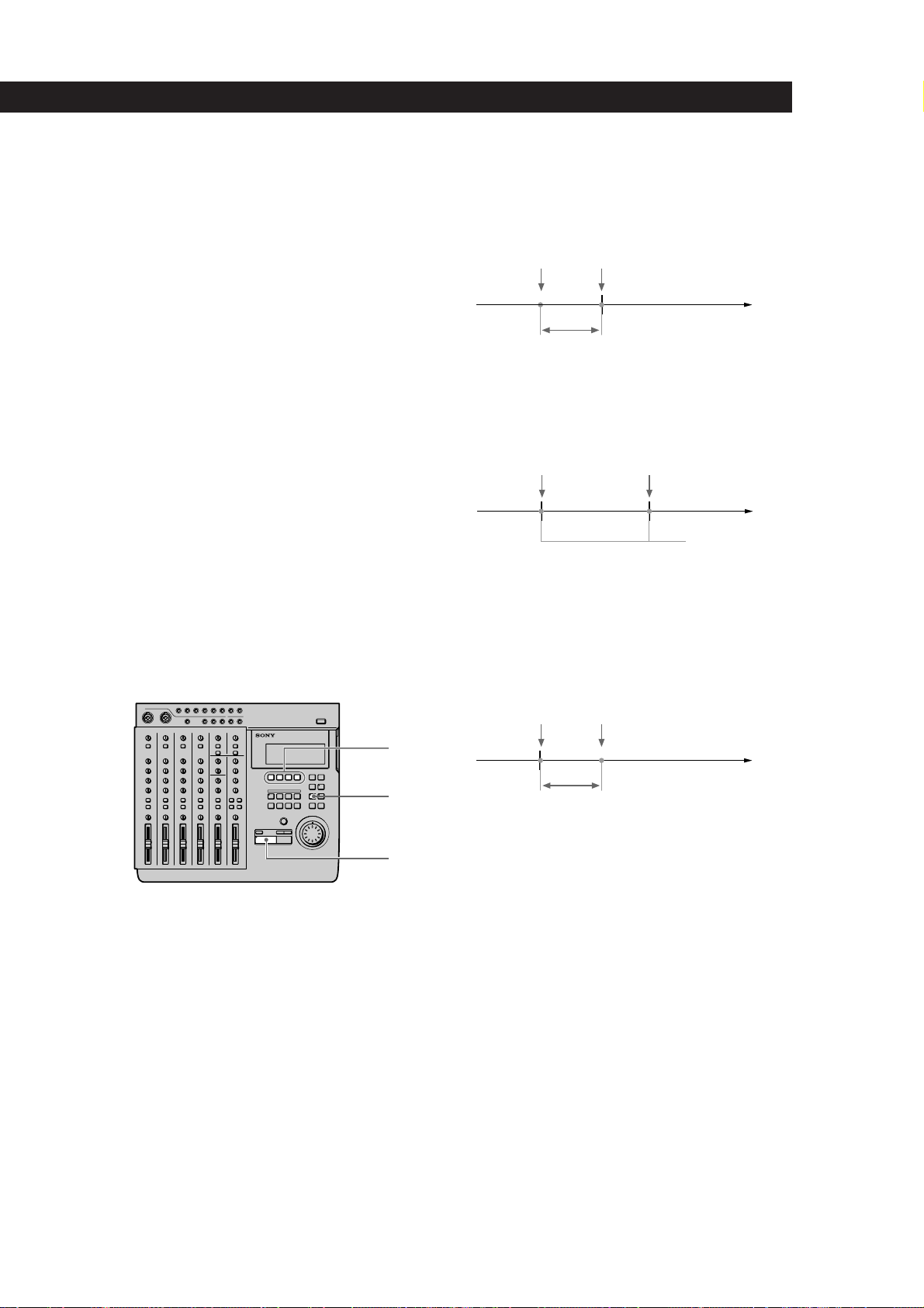
Rehearsing the punch-in/out
You can check to make sure the record start (punch in)
and record stop (punch out) positions are correct
before starting punch-in/out recording. (rehearsal
function)
When the rehearsal function is operative, the specified
section is muted through the CUE monitor (the actual
sound has not been erased). If the settings are incorrect
re-specify the in and out points until the correct section
has been specified. See “Correcting the position of the
locate point” (page 32) for details.
The following procedure shows how to carry out the
rehearsal.
3 Press ( PLAY.
Playback starts pre-rolling from a point slightly
before the punch-in position in accordance with
the “Pre-roll/Post-roll” system setting.
Start of playback
Pre-roll time setting
When using CUE monitor, the sound between the
punch-in and punch-out positions of the track to
be recorded (the track whose REC SELECT key
was pressed) cannot be heard.
Punch in position
Rehearsal post-rolls to a point slightly after the
punch out position in accordance with the “Pre-
roll/Post-roll” system setting and then stops.
Once rehearsal has stopped, the disc
automatically returns to the original point where
the AUTO PUNCH key was pressed.
Punch in position
Punch out position
No sound between
these points.
1 Press AUTO PUNCH when the disc is in stop
mode.
The indicator on AUTO PUNCH lights up.
REC and the indicator on RHSL start blinking,
and the unit enters record pause mode.
When “Undo Function On/Off” in the system
settings is set to “Enabl (on)”, the indicator on the
UNDO key changes accordingly.
2 Press the REC SELECT key for the track to be
recorded.
Punch out position
End of playback
2
1
3
To stop in the middle of rehearsal
Press p STOP.
Post-roll time setting
(continued)
23
EN
Page 24
Recording
Recording
1
Press AUTO PUNCH when the disc is stopped.
The indicator on AUTO PUNCH lights.
REC and the indicator on RHSL start blinking,
and the unit enters record pause mode.
When “Undo Function On/Off” in the system
settings is set to “Enabl (on)”, the indicator on the
UNDO key changes accordingly.
2 Press RHSL to cancel rehearsal mode.
When “Undo Function On/Off” in the system
settings is set to “Enabl (on)”, and undo is
possible, the unit proceeds to back up the data.
Turn the jog dial to set the counter to the point
1
you want to hear.
Pressing the IN key automatically locates the punch-in
point.
2 Press CUE to prepare for monitoring.
2
Adjust the monitor volume using the respective
TRACK knobs and the MONITOR knob.
1
3 Press ( PLAY.
Playback begins.
3
To rerecord
Follow the “Recording” procedure to the left.
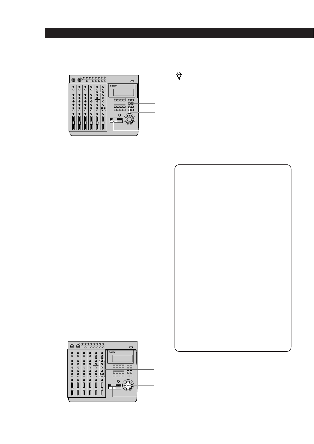
Using the UNDO function with auto
punch-in/out recording
You can undo the punch-in/out immediately after
execution if the system UNDO setting is set to
“Enabl (on)” and the undo indicator is lit green.
To carry out the undo function, press UNDO.
Pressing undo again lets you redo the undone
section (redo function).
3 Press ( PLAY.
Playback begins. Play together with the
previously recorded performance.
When the recorder arrives at the preset punch-in
position, record mode is activated automatically
and the input sound is recorded on the specified
track up to the punch-out point. When the
recorder reaches the punch-out point, recording
stops automatically, but playback continues until
the post-roll point is reached.
When playback is stopped the player
automatically returns to the original point.
Checking the Recording
Note
Carrying out another edit operation, starting a recording,
or removing the disc after carrying out the undo or redo
functions will make it impossible to undo the previous
edit operation.
Notes about the color of the indicator on the UNDO
key.
The color which the indicator on the UNDO key
lights shows the current status. (Sometimes the
indicator is off).
GREEN : undo is possible. (Redo has been carried
out.)
RED : undo has been carried out
(blinking) : in the process of carrying out the undo
(or redo) function.
(off) : undo is not possible. (In cases where the
previous operation cannot be undone (etc.).)
2
1
24
3
EN
Page 25
Manual Punch-In/Out
Recording
Manual punch-in/out recording is when you start and
stop recording manually with the appropriate timing
instead of presetting the section to be recorded.
EXAMPLE: To punch-in/out a section on track 1.
Before punch-in/out After punch-in/out
Punch in
mark
Punch out
mark
Punch in
mark
Punch out
mark
b
Only this area
is recorded.
Preparations
Recording
5 Press CUE, then turn the TRACK knob
corresponding to the track containing the
recorded sound you want to hear while recording
to adjust the sound to a level which can be
monitored.
Use the MONITOR knob to adjust the monitor
level.
6 Use the fader to adjust the recording level.
Play a relatively loud phrase and make
adjustments by watching the level meter for the
track you want to record.
If necessary, you can use the TRIM knob to adjust
the recording level and equalizer.
Adjust the recording level so that the CLIP
indicator does not light.
Adjust the TRIM knob so that the proper level is
obtained when the fader is set between 7 and 8 to
achieve good frequency characteristics.
Recording
(1) Using the REC key to punch-in/out.
1
3
4,5
2,6
1 Set the INPUT switch for the channel to which
you will input the instrument or microphone
sound to LINE/MIC (up position).
2 Set the fader for the channel to which you will
input the sound to about 7 or 8.
3 Use the ASSIGN switch and PAN knobs to direct
the sound to the group path you want to record.
4 Press the monitor track set key corresponding to
the group path number you selected in step 3.
1
5
3,4
2,4
1 Press the REC SELECT key corresponding to the
group path you want to record to specify the track
to be recorded.
2 Turn the jog dial to set the counter to a position
before the point where you want to start
recording, then press ( PLAY.
Playback begins.
3 When you reach the point where you want to start
recording (the punch in point), press REC.
The REC key lights up and recording begins.
5
(continued)
25
EN
Page 26
Recording
1
2
3
Press ( PLAY when you reach the point where
4
you want to stop recording (the punch out point).
The REC key goes out and the unit stops
recording and switches to playback mode.
5 Press p STOP.
Playback ends.
Setting the ASSIGN SW on the front of the unit to “REC
IO” lets you use a foot switch (etc.) to activate punchin/out recording. See “System Settings” (page 17) for
details.
(2) Using the REC SELECT key to punch-in/out
4,5
3,4
1
52,4
Checking the Recording
1 Turn the jog dial to set the counter to the point
you want to hear.
2 Press CUE to prepare for monitoring.
Adjust the monitor volume using the respective
TRACK knobs and the MONITOR knob.
3 Press ( PLAY.
Playback begins.
1 Turn the jog dial to set the counter to a position
before the point where you want to start
recording, then press REC.
The REC key start blinking and the unit switches
to record pause mode.
2 Press ( PLAY.
Playback starts, while the REC key continues
blinking.
3 When you reach the point where you want to start
recording (the punch in point), press the REC
SELECT key for the track you want to record.
The REC key lights steadily and recording begins
on the specified track.
4 When you reach the point where you want to stop
recording (the punch out point), press REC
SELECT key for the track being recorded or press
the ( PLAY key.
The REC key starts blinking, or goes out, and the
unit stops recording and switches to playback
mode.
To rerecord
Follow the “Recording” procedure on the previous
page.
26
5 Press p STOP.
Playback ends.
EN
Page 27
Mix Write Recording (Basics)
N
R
You can record other sounds on top of a previously
recorded track.
The following is an explanation of the mix write
concept.
EXAMPLE: Recording a chorus on top of the vocals
recorded on track 1.
Since the vocals recorded on track 1 are all
assigned to channel 1, connect the microphone to
another channel’s input jack.
During recording, the chorus vocals are mixed
with the original vocals and recorded to track 1.
Recording
3 Set the channel 2 ASSIGN switch and PAN knobs
to direct the sound to track 1.
(Set the chorus vocals input from channel 2 to be
recorded on track 1.)
ASSIGN ASSIGN ASSIGN ASSIGN
1 2 1 2 1 2 1 2
3 43 43 43 4
L R L R L R L R
Press down
PANPANPANPAN
Turn all the
way toward
“L”.
Record chorus
b
Previously
recorded vocals
Preparations for recording
EXAMPLE: Recording a chorus on top of the vocals
recorded on track 1. (For this example we will
input the chorus to the INPUT CH2 jack.)
7
3
5
9
2
1 Set the channel 2 INPUT switch to LINE/MIC (up
position).
(Set channel 2 to receive the input sound).
Chorus /
vocal mix
14
11
6
10
8
8
4 Press down the channel 1 INPUT switch.
(Input the playback sound from the recorder
(TRACK 1) to channel 1.)
5 Set the channel 1 ASSIGN switch and PAN knobs
to direct the playback sound from the recorder to
track 1.
(Set the playback sound from the recorder to be
recorded on track 1.)
3
PANPANPANPAN
L
Press down
Turn all the
way toward
“L”.
ASSIGN ASSIGN ASSIGN ASSIG
1 2 1 2 1 2 1
3 43 43 4
L R L R L R
6 Prepare the monitor.
• Press the monitor track key corresponding to
the group path selected in steps 3 and 5 (in this
case, press down the 1-2 button).
• If you want to monitor the sound of tracks 2
and 3 press the CUE key.
• Turn the MONITOR knob and the TRACK
knob(s) to adjust the sound to a level that can be
monitored.
7 Input a loud phrase and use the channel 2 TRIM
knob to adjust the recording level.
8 Press ( PLAY.
Playback begins.
2 Set the fader for channel 2 to about 7 or 8.
(continued)
27
EN
Page 28
Recording
b
A
B
C
D
A B C D
9 Use the channel 1 and 2 faders to adjust the
balance between the vocals and chorus to be
recorded on track 1.
You may also need to adjust the monitor balance
at this time.
Press the p STOP key after making the necessary
adjustments.
10 Turn the jog dial to locate the point on the counter
where the recording will begin.
Mix Write Recording (Applied
Operations)
Mix write also comes in handy in a variety of other
situations not mentioned on the previous pages. In this
section we will provide 2 additional examples of mix
write recording.
11 Press the REC SELECT key for track 1.
This makes it possible to record on track 1.
Recording
Press REC.
1
The unit switches to record pause mode.
2 Press ( PLAY.
Recording begins.
Play together with the previously recorded
performance.
3 When you’ve finished playing, press p STOP.
Checking the Recording
Turn the jog dial to set the counter to the point
1
you want to hear.
2 Press CUE to prepare for monitoring.
Adjust the monitor volume using the respective
TRACK knobs and the MONITOR knob.
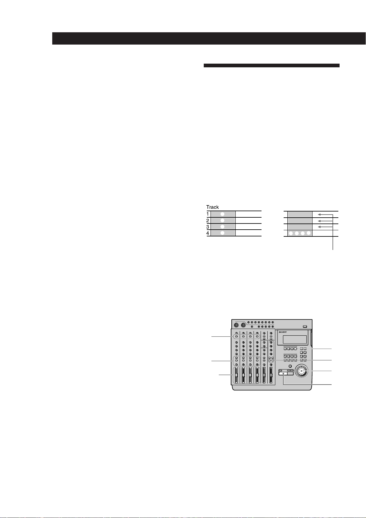
EXAMPLE 1: Recording the sound from
tracks 1~4 to track 4 (Ping Pong Recording)
Recording the previously recorded sound from tracks
1~4 onto track 4.
This allows you to use tracks 1~3 as blank tracks for
recording other parts.
The previously recorded contents of tracks
1~3 remain, but the contents of tracks 1~4
have been recorded together on track 4.
Preparations
28
EN
3 Press ( PLAY.
Playback begins.
1
3
2,6
1 Press down the INPUT switches on channels 1~4.
(Set channels 1~4 to receive the (TRACK) sound
played back from the recorder.)
2 Set the faders for channels 1~4 to about 7 or 8.
8
4
7
5
Page 29
Recording
3 Set the ASSIGN switches and PAN knobs for
channels 1~4 to direct the sound to track 4.
(Set the playback sounds input from the recorder
to channels 1~4 to be recorded on track 4.)
ASSIGN ASSIGN ASSIGN ASSIGN
1 2 1 2 1 2 1 2
3 43 43 43 4
PANPANPANPAN
L R L R L R L R
Press down
Turn all the
way toward
“R”.
4 Prepare the monitor.
• Press the monitor track key corresponding to
the group path selected in step 3 (in this case,
press 3-4).
• Turn the MONITOR knob and the TRACK
knob(s) to adjust the sound to a level that can be
monitored.
5 Press ( PLAY.
Playback begins.
6 Use the faders for channels 1~4 to adjust the
record balance of the sound to be recorded on
track 4.
You may also need to adjust the monitor balance
at this time.
Press the p STOP key after making the necessary
adjustments.
7 Turn the jog dial to locate the point on the counter
where the recording will begin.
8 Press the REC SELECT key for track 4.
This makes it possible to record on track 4.
Checking the Recording
1 Turn the jog dial to set the counter to the point
you want to hear.
2 Press CUE to prepare for monitoring.
Adjust the monitor volume using the respective
TRACK knobs and the MONITOR knob.
3 Press ( PLAY.
Playback begins.
Make sure the CLIP indicator on the level meter
does not light.
EXAMPLE 2: Recording the sound from
tracks 1~4 to tracks 1 and 2 (Bounce
Recording)
Recording the previously recorded sound from tracks
1~4 in a stereo mix to tracks 1 and 2.
This allows you to use tracks 3 and 4 as blank tracks for
recording other parts.
A
B
C
D
The previously recorded contents of tracks 3 and 4
remain, but the contents of tracks 1~4 have been
recorded together in a stereo mix on tracks 1 and 2.
b
A B C D
(continued)
Recording
1 Press REC.
The unit switches to record pause mode.
2 Press ( PLAY.
Recording begins.
Play together with the previously recorded
performance.
3 When you’ve finished playing, press p STOP.
29
EN
Page 30
Recording
Preparations
1
8
4
3
2,6
7
5
1 Press down the INPUT switches on channels 1~4.
(Set channels 1~4 to receive the (TRACK) sound
played back from the recorder.)
2 Set the faders for channels 1~4 to about 7 or 8.
3 Set the ASSIGN switches and PAN knobs for
channels 1~4 to direct the sound to tracks 1 and 2.
(Set the playback sounds input from the recorder
to channels 1~4 to be recorded on tracks 1 and 2.)
Recording
1 Press REC.
The unit switches to record pause mode.
2 Press ( PLAY.
Recording begins.
Play together with the previously recorded
performance.
3 When you’ve finished playing, press p STOP.
Checking the Recording
1 Turn the jog dial to set the counter to the point
you want to hear.
2 Press CUE to prepare for monitoring.
Adjust the monitor volume using the respective
TRACK knobs and the MONITOR knob.
3 Press ( PLAY.
Playback begins.
4 Prepare the monitor.
• Press the monitor track key corresponding to
the group path selected in step 3 (In this case,
press 1-2).
• Turn the MONITOR knob and the TRACK
knob(s) to adjust the sound to a level that can be
monitored.
5 Press ( PLAY.
Playback begins.
6 Use the faders for channels 1~4 to adjust the
record balance of the sound to be recorded on
tracks 1 and 2.
You may also need to adjust the monitor balance
at this time.
Press the p STOP key after making the necessary
adjustments.
7 Turn the jog dial to locate the point on the counter
where the recording will begin.
8 Press the REC SELECT key for tracks 1 and 2.
This makes it possible to record on tracks 1 and 2.
30
EN
Page 31

Editing Part of a Song (Track Edit)
Editing Part of a Song (Track Edit)
Track Edit Overview
The track editing operations let you specify a part (an
arbitrary section of an arbitrary track) and copy it over
another part, move it to another position, or remove
the sound from it. You can also switch the positions of
two parts.
Additionally, you can edit between different songs as
well as within the same song.
The track editing functions consist of the following:
• Track Copy (duplicating a part) n page 33
• Track Move (moving a part) n page 34
• Track Exchange (switching the positions of 2 parts)
n page 35
• Track Erase (erasing a part) n page 36
Using the Undo Function with track
editing operations
You can undo an edit immediately after execution if
the undo indicator is lit green.
To carry out the undo function, press UNDO.
Pressing undo again lets you redo the undone edit
operation (redo function).
Specifying the Locate Points
Before editing, it is necessary to specify the locate
points (edit points). There are the following eleven
types of locate points:
• IN (edit start) point
Represents the beginning of the part to be edited.
• OUT (edit end) point
Represents the end of the part to be edited.
• DEST (edit destination) point
Represents the place where the part will be copied to
during the copy operation (etc.).
• A~H points
Additional arbitrary locate points (not used for
editing operations).
IN point
OUT point
DEST (destination) point
Note
Carrying out another edit operation, starting a recording,
or removing the disc after carrying out the undo or redo
functions will make it impossible to undo the previous
edit operation.
Notes about the color of the indicator on the UNDO
key.
The color which the indicator on the UNDO key
lights shows the current status. (Sometimes the
indicator is off).
GREEN : undo is possible. (Redo has been carried
out.)
RED : undo has been carried out
(blinking) : in the process of carrying out the undo
(or redo) function.
(off) : undo is not possible. (In cases where the
previous operation cannot be undone (etc.).)
Setting edit points by specifying the time/
bar
Use the following procedure when you know the
time/bar of the locate points for the desired part.
3
2
1
1 Turn the jog dial during stop mode to display the
time/bar you desire.
Holding down the SHIFT key and pressing the
DISPLAY key lets you switch the display between
time and bars.
To select the desired song, use the = and +
keys.
(continued)
31
EN
Page 32

Editing Part of a Song (Track Edit)
1,5
3
2
4
Press MARK.
2
The indicator on the MARK key starts blinking.
3 Press the key for the locate point you desire.
• IN point : Press IN.
• OUT point : Press OUT.
• DEST (destination) point : Hold down the
SHIFT key and press IN.
• A~D (E~H) points : Press A~D (Hold down the
SHIFT key and press A~D).
The time/bar in the display is set as the respective
locate point.
Setting edit points while listening to the
sound being played back
Use the following procedure to set locate points while
listening to the sound being played back.
2
Correcting the position of the locate point
1 Press the key for the point you wish to correct.
• IN point : Press IN.
• OUT point : Press OUT.
• DEST (destination) point : Hold down the
SHIFT key and press IN.
• A~D (E~H) points : Press A~D (Hold down the
SHIFT key and press A~D).
The time/bar for the respective locate point
appears in the display.
3
2 Press RHSL.
The indicator on the RHSL key starts to blink and
1
playback repeats around the locate point.
• When the rehearsal mode (page 18) setting is Â:
the volume increases when the locate point is
passed.
32
EN
1 Press ( PLAY.
Playback begins.
2 Press MARK before setting the locate point.
The indicator on the MARK key starts blinking.
3 Press the key for the locate point you desire.
• IN point : Press IN.
• OUT point : Press OUT.
• DEST (destination) point : Hold down the
SHIFT key and press IN.
• A~D (E~H) points : Press A~D (Hold down the
SHIFT key and press A~D).
The locate point is set at the place where you
press the IN, OUT ,DEST or A~D (E~H) key.
Playback
start point Locate point
Change in volume
(about 12 dB)
• When the rehearsal mode (page 18) setting is µ:
the volume decreases when the locate point is
passed.
Playback
start point
Change in volume
(about 12 dB)
Locate point
Playback
end point
Roll time as set in
the system setting
Playback
end point
Roll time as set in
the system setting
Page 33

During rehearsal mode, press the = or + key to
switch between increased or decreased volume after the
locate point.
3 Turn the jog dial to adjust the position of the
locate point.
The locate point moves in proportion to the
rotation of the jog dial each time the section is
repeated.
4 Press MARK.
The indicator on the MARK key starts blinking.
Editing Part of a Song (Track Edit)
Copying a Part (Track Copy)
You can copy part of a track and place it in another
location. If the location points are in the same position,
you can copy parts from more than one track at the
same time.
IN point
OUT point
Destination point
5 Press the key for the locate point you desire.
Playback stops and the locate point is set to the
new position.
To stop before completing the correction
Press p STOP to stop playback.
Notes
• Be sure to set the out point at a higher number than the in
point.
• Be sure to set the punch-in/out positions within the same
song.
Track 1
Track 2
Track 3
Track 4
The original sound recorded after the destination point
is erased and rewritten by the part between the in and
out points.
A
B
A
B
Preparations
Set the following locate points before carrying out the
edit operation.
• IN point : the beginning of the part to be copied.
• OUT point : the end of the part to be copied.
• DEST (destination) point : the beginning of the part
to be rewritten.
See “Specifying the Location Points” (page 31) for
details on how to set the location points.
Editing Operation
1
7
1 Press EDIT.
[EDIT] appears in the display.
3,5,6
2,4
(continued)
33
EN
Page 34

Editing Part of a Song (Track Edit)
3,5,6
2,4
7
1
Turn the jog dial so that “Trak Copy” appears in
2
the display.
The name of the edit function starts blinking in
the display.
3 Press ENTER.
The edit setting items appear in the display.
4 Turn the jog dial to display the setting you desire.
This determines which tracks the part will be
copied from and which tracks the part will be
copied to.
Use the jog dial to specify the copy destination
track numbers in the space underneath the track
indicator(s) (
Example display:
1
mark) for the part to be copied.
2 3
001:Cpy 34
Moving a Part (Track Move)
You can move part of a track to a different position in a
different track.
IN
OUT
Destination
point
point
point
A
A
B
B
The space between the original in and out points
becomes a silent area.
b
IN
point
OUT
point
Destination
point
A
B
Becomes
silent area
To set other tracks press ENTER and proceed to
the next step.
Press EXIT to return to the original settings.
If you do not want to specify any tracks, leave the
destination track number display empty.
5 Press ENTER.
Once all the track settings have been displayed,
“OK?” appears in the display.
6 Press ENTER again.
The selected part is copied.
If you do not wish to carry out the edit operation,
press EXIT.
When the edit operation has finished, the edit
select screen reappears.
7 Press EXIT.
This completes the edit operation.
Note
It is not possible to set the destination point between the in
and out points when copying to the same track.
Preparations
Set the following locate points before carrying out the
edit operation.
• IN point : the beginning of the part to be copied.
• OUT point : the end of the part to be copied.
• DEST (destination) point : the beginning of the part
to be rewritten.
See “Specifying the Locate Points” (page 31) for details
on how to set the location points.
Editing Operation
34
EN
1 Press EDIT.
[EDIT] appears in the display.
2 Turn the jog dial so that “Trak Move” appears in
the display.
The name of the edit function starts blinking in
the display.
Page 35

Press ENTER.
3
The edit setting items appear in the display.
Editing Part of a Song (Track Edit)
Switching the Locations of 2
4 Turn the jog dial to display the setting you desire.
This determines which tracks the part will be
moved to.
Use the jog dial to display the move destination
track numbers in the space below the move origin
track number indicator(s) (
Example display:
1
mark).
2 3
001:Mov 34
To set other tracks press ENTER and proceed to
the next step.
Press EXIT to return to the original settings.
If you do not want to specify any tracks, leave the
destination track number display empty.
5 Press ENTER.
Once all the track settings have been displayed,
“OK?” appears in the display.
6 Press ENTER again.
The selected part is copied.
If you do not wish to carry out the edit operation,
press EXIT.
When the edit operation has finished, the edit
select screen reappears.
Parts (Track Exchange)
You can switch the location one part of a track with
another part of any other track.
IN point
OUT point
Destination point
A
B
C
C
D
A
b
D
Preparations
Set the following locate points before carrying out the
edit operation.
• IN point : the beginning of the part to be copied.
• OUT point : the end of the part to be copied.
• DEST (destination) point : the beginning of the part
to be rewritten.
See “Specifying the Locate Points” (page 31) for details
on how to set the location points.
B
7 Press EXIT.
This completes the edit operation.
Note
It is not possible to set the destination point between the in
and out points when moving within the same track.
Editing Operation
1
7
3,5,6
2,4
1 Press EDIT.
[EDIT] appears in the display.
2 Turn the jog dial so that “Trak Xchnge” appears
in the display.
The name of the edit function starts blinking in
the display.
(continued)
35
EN
Page 36

Editing Part of a Song (Track Edit)
Press ENTER.
3
The edit setting items appear in the display.
Erasing a Part (Track Erase)
4 Turn the jog dial to display the setting you desire.
This determines which tracks the parts will be
exchanged to.
Use the jog dial to display the exchange
destination track number(s) below the exchange
1 2
1
mark).
origin track number indicator(s) (
Example display:
001:Xcg24
To set other tracks press ENTER and proceed to
the next step.
Press EXIT to return to the original settings.
If you do not want to specify any tracks, leave the
destination track number display empty.
5 Press ENTER.
Once all the track settings have been displayed,
“OK?” appears in the display.
6 Press ENTER again.
The selected part is copied.
If you do not wish to carry out the edit operation,
press EXIT.
When the edit operation has finished, the edit
select screen reappears.
You can erase part of a track. The part which was
erased becomes a part with no sound.
IN
point
OUT
point
A
B
Becomes a part with no sound
b
IN
point
OUT
point
Preparations
Set the following locate points before carrying out the
edit operation.
• IN point : the beginning of the part to be copied.
• OUT point : the end of the part to be copied.
See “Specifying the Locate Points” (page 31) for details
on how to set the location points.
Editing Operation
7 Press EXIT.
This completes the edit operation.
Note
It is not possible to set the edit points to exchange
overlapping parts.
1
7
3,5,6
2,4
1 Press EDIT.
[EDIT] appears in the display.
2 Turn the jog dial so that “Trak Erase” appears in
the display.
The name of the edit function starts blinking in
the display.
36
EN
Page 37

Press ENTER.
3
The edit setting items appear in the display.
4 Turn the jog dial to display the setting you desire.
This determines which tracks the part will be
erased from.
Use the jog dial to display the track number(s)
containing the part(s) to be erased below the
respective track number indicator(s) (
Example display:
1 3
1
mark).
001:Ers1 3
To set other tracks press ENTER and proceed to
the next step.
Press EXIT to return to the original settings.
If you do not want to specify a track, leave an
empty space below the respective track number
indicator.
Editing Part of a Song (Track Edit)
5 Press ENTER.
“OK?” appears in the display.
6 Press ENTER again.
The selected part is copied.
If you do not wish to carry out the edit operation,
press EXIT.
When the edit operation has finished, the edit
select screen reappears.
7 Press EXIT.
This completes the edit operation.
37
EN
Page 38

Changing the Construction of a Song (Section Edit)
Section Edit Overview
The section editing operations let you specify sections
common to all 4 tracks and move them to other
positions in the song, duplicate them, or remove them.
You can also switch the positions of two sections.
The section editing functions consist of the following:
• Section Move (moving a section) n page 39
• Section Exchange (switching 2 sections) n page 40
• Section Insert (duplicating and inserting a section)
n page 41
• Section Delete (for deleting a section) n page 42
Notes
• It is not possible to perform recording operations, such as
punch-in/out recording on a song that has been modified
with section editing.
In order to perform punch-in/out recording operations
after a song has been edited, you must copy the entire
song, then record or edit the copied version of the song.
“:” blinks next to the song number of songs which have
been modified with the section edit function.
See “Copying a Song (Song Copy)” on page 43 for details
on how to copy a song.
• Short sections* cannot be edited. This is due to the nature
of the MD system, and is not a malfunction.
* With 4 tracks = less than approximately 4 seconds.
With 2 tracks = less than approximately 8 seconds.
With 1 track = less than approximately 16 seconds.
• Section editing is only complete once the TOC data has
been updated. You can update the TOC data by pressing
STOP during stop mode. The TOC data is also updated
automatically when the disc is ejected. Therefore, always
eject the disc before turning off the power. Not only is
there a danger of loosing the song being edited, there is
also a possibility of loosing the contents of the entire
disc.
Using the Undo Function with section
editing operations
You can undo an edit immediately after execution if
the undo indicator is lit green.
To carry out the undo function, press UNDO.
Pressing undo again lets you redo the undone edit
operation (redo function).
Note
Carrying out another edit operation, starting a recording,
or removing the disc after carrying out the undo or redo
functions will make it impossible to undo the previous
edit operation.
Notes about the color of the indicator on the UNDO
key.
The color which the indicator on the UNDO key
lights shows the current status. (Sometimes the
indicator is off).
GREEN : undo is possible. (Redo has been carried
out.)
RED : undo has been carried out
(blinking) : in the process of carrying out the undo
(or redo) function.
(off) : undo is not possible. (In cases where the
previous operation cannot be undone (etc.).)
Specifying the Locate Points
Before editing, it is necessary to specify the locate
points (edit points). There are the following three types
of locate points:
• IN (edit start) point :
Represents the beginning of the section to be edited.
• OUT (edit end) point :
Represents the end of the section to be edited.
• DEST (edit destination) point :
Represents the edit destination for move, exchange,
and insert operations.
See “Specifying the Locate Points” on page 31 for
details on how to set the location points.
38
Notes
• Be sure to set the out point at a higher number than the in
point.
• Be sure to set the punch-in/out positions within the same
song.
EN
Page 39

Changing the Construction of a Song (Section Edit)
Moving a Section (Section
Move)
2 Turn the jog dial so that “Sect Move” appears in
the display.
The name of the edit function starts blinking in
the display.
You can move a section to a different place in the song.
The section to be moved is inserted at the point
specified by the destination point.
IN point
OUT point
Destination point
A B C CB A
The selected section is moved.
A disappears and is moved to
the destination point.
b
Preparations
Set the following locate points before carrying out the
edit operation.
• IN point : the beginning of the part to be copied.
• OUT point : the end of the part to be copied.
• DEST (destination) point : the beginning of the part
to be rewritten.
See “Specifying the Location Points” (page 31) for
details on how to set the location points.
3 Press ENTER.
“OK?” appears in the display.
001:Mov,OK?
4 Press ENTER again.
The selected edit operation is carried out.
To start over again from the beginning, or quit the
edit operation, press EXIT instead of ENTER.
When the edit operation has finished, the edit
select screen reappears.
To carry out another edit operation in succession
use the jog dial to specify the operation you
desire.
5 Press EXIT.
This completes the edit operation.
Editing Operation
1
5
1 Press EDIT.
[EDIT] appears in the display.
3,4
2
EN
39
Page 40

Changing the Construction of a Song (Section Edit)
3 Press ENTER.
Switching the Locations of 2
“OK?” appears in the display.
Sections (Section Exchange)
001:Xcg,OK?
You can switch the location of two sections.
4 Press ENTER again.
IN point
OUT point
Destination point
A B AB
The selected sections
are exchanged.
b
Preparations
Set the following locate points before carrying out the
edit operation.
• IN point : the beginning of the part to be copied.
• OUT point : the end of the part to be copied.
• DEST (destination) point : the beginning of the part
to be rewritten.
See “Specifying the Locate Points” (page 31) for details
on how to set the location points.
The selected edit operation is carried out.
To start over again from the beginning, or quit the
edit operation, press EXIT instead of ENTER.
When the edit operation has finished, the edit
select screen reappears.
To carry out another edit operation in succession
use the jog dial to specify the operation you
desire.
5 Press EXIT.
This completes the edit operation.
Note
It is not possible to set the destination point between the in
and out points.
Editing Operation
1
5
3,4
2
1 Press EDIT.
[EDIT] appears in the display.
2 Turn the jog dial so that “Sect Xchnge” appears in
the display.
The name of the edit function starts blinking in
the display.
40
EN
Page 41

Changing the Construction of a Song (Section Edit)
Inserting Another Section
(Section Insert)
This function lets you copy a section and insert it at
another place in the song.
IN point
OUT point
Destination point
A A A
The original section is copied and
inserted at the destination point.
b
3 Press ENTER.
“OK?” appears in the display.
001:Ins,OK?
4 Press ENTER again.
The selected edit operation is carried out.
To start over again from the beginning, or quit the
edit operation, press EXIT instead of ENTER.
When the edit operation has finished, the edit
select screen reappears.
To carry out another edit operation in succession
use the jog dial to specify the operation you
desire.
5 Press EXIT.
This completes the edit operation.
Preparations
Set the following locate points before carrying out the
edit operation.
• IN point : the beginning of the part to be copied.
• OUT point : the end of the part to be copied.
• DEST (destination) point : the beginning of the part
to be rewritten.
See “Specifying the Locate Points” (page 31) for details
on how to set the location points.
Editing Operation
1
5
3,4
2
1 Press EDIT.
[EDIT] appears in the display.
2 Turn the jog dial so that “Sect Insert” appears in
the display.
The name of the edit function starts blinking in
the display.
41
EN
Page 42

Changing the Construction of a Song (Section Edit)
3 Press ENTER.
Deleting a Section (Section
“OK?” appears in the display.
Delete)
001:Del,OK?
This function lets you delete a section of the song.
4 Press ENTER again.
IN point
OUT point
A B C A C
The specified section is deleted
and the in and out points are
joined together.
b
Preparations
The selected edit operation is carried out.
To start over again from the beginning, or quit the
edit operation, press EXIT instead of ENTER.
When the edit operation has finished, the edit
select screen reappears.
To carry out another edit operation in succession
use the jog dial to specify the operation you
desire.
5 Press EXIT.
This completes the edit operation.
Set the following locate points before carrying out the
edit operation.
• IN point : the beginning of the part to be copied.
• OUT point : the end of the part to be copied.
See “Specifying the Locate Points” (page 31) for details
on how to set the location points.
Editing Operation
1
5
3,4
2
Press EDIT.
1
[EDIT] appears in the display.
42
2 Turn the jog dial so that “Sect Delete” appears in
the display.
The name of the edit function starts blinking in
the display.
EN
Page 43

Editing Entire Songs (Song Edit)
Editing Entire Songs (Song Edit)
Song Edit Overview
The following sections show you how to divide a
completed song and connect 2 adjacent songs (etc.) so
you can easily locate the positions you desire on the
recorded disc.
The following is a list of song editing functions :
• Song Copy (copying a song) n page 43
• Song Move (moving a song ) n page 44
• Song Exchange (switching the positions of 2 songs)
n page 45
• Song Divide (dividing 1 song into 2 different songs)
n page 46
• Song Combine (combining 2 songs) n page 47
• Song Delete (deleting a song) n page 48
• Song Name (naming a song) n page 49
• Song Tempo (creating a tempo map) n page 53
Note
Song editing is only complete once the TOC data has been
updated. You can update the TOC data by pressing STOP
during stop mode. The TOC data is also updated
automatically when the disc is ejected. Therefore, always
eject the disc before turning off the power. Not only is
there a danger of loosing the song being edited, there is
also a possibility of loosing the contents of the entire disc.
Copying a Song (Song Copy)
This function lets you duplicate a song. Newly created
copy is treated as a new recording and becomes the last
song on the disc. This is a convenient way to backup
songs before editing.
Copying the second song.
123 4
AB C
123
AB C B
The copy of the second song
becomes the fourth song
1
7
Before copying
4
After copying
3,5,6
Using the Undo Function with section
editing operations
You can undo an edit immediately after execution if
the undo indicator is lit green.
To carry out the undo function, press UNDO.
Pressing undo again lets you redo the undone edit
operation (redo function).
Note
Carrying out another edit operation, starting a recording,
or removing the disc after carrying out the undo or redo
functions will make it impossible to undo the previous
edit operation.
Notes about the color of the indicator on the UNDO
key.
The color which the indicator on the UNDO key
lights shows the current status. (Sometimes the
indicator is off).
GREEN : Undo is possible. (Or Redo has been
carried out.)
RED : Undo has been carried out
(blinking) : In the process of carrying out the undo
(or redo) function.
(off) : Undo is not possible. (In cases where the
previous operation cannot be undone (etc.).)
2,4
1 Press EDIT.
[EDIT] appears in the display.
2 Turn the jog dial so that “Song Copy” appears in
the display.
The name of the edit function starts blinking in
the display.
3 Press ENTER.
The edit setting items appear in the display.
4 Turn the jog dial to display the number song you
want to copy.
Cpy 002
5 Press ENTER
“OK?” appears in the display.
(continued)
43
EN
Page 44

Editing Entire Songs (Song Edit)
3,5,
7,8,
2,4,6
9
1
Press ENTER again.
6
The selected song is copied.
To start over again from the beginning, or quit the
edit operation, press EXIT instead of ENTER.
When the edit operation has finished, the edit
select screen reappears.
To carry out another edit operation in succession
use the jog dial to specify the operation you
desire.
7 Press EXIT.
This completes the edit operation.
Moving a Song (Song Move)
This function lets you change the order of the songs by
moving the song you select to a different position.
Moving the second song to the third song.
123 4
AB C D
12 34
ABCD
Before copying
After copying
1 Press EDIT.
[EDIT] appears in the display.
2 Turn the jog dial so that “Song Move” appears in
the display.
The name of the edit function starts blinking in
the display.
3 Press ENTER.
The edit setting items appear in the display.
Mov 002>003
4 Turn the jog dial to display the song number you
want to move.
5 Press ENTER.
44
EN
Page 45

Turn the jog dial to display the number you want
6
to move the selected song to.
Editing Entire Songs (Song Edit)
Changing the Song Order
7 Press ENTER
“OK?” appears in the display.
8 Press ENTER again.
The selected song is moved.
To start over again from the beginning, or quit the
edit operation, press EXIT instead of ENTER.
When the edit operation has finished, the edit
select screen reappears.
To carry out another edit operation in succession
use the jog dial to specify the operation you
desire.
9 Press EXIT.
This completes the edit operation.
(Song Exchange)
This function lets you switch the position of 2 songs of
your choice. New consecutive song numbers are
assigned automatically.
Switching songs 2 and 4.
123 4 5
AB C D
12 3 54
AD CB
1
9
Before copying
After copying
3,5,
7,8,
2,4,6
1 Press EDIT.
[EDIT] appears in the display.
2 Turn the jog dial so that “Song Xchnge” appears
in the display.
The name of the edit function starts blinking in
the display.
3 Press ENTER.
The edit setting items appear in the display.
Xcg 002-004
4 Turn the jog dial to display the first song number
you want to exchange.
5 Press ENTER.
(continued)
45
EN
Page 46

Editing Entire Songs (Song Edit)
002:Div,OK?
Turn the jog dial to display the song number you
6
want to exchange the first song with.
Dividing a Song (Song Divide)
7 Press ENTER
“OK?” appears in the display.
8 Press ENTER again.
The selected songs are exchanged.
To start over again from the beginning, or quit the
edit operation, press EXIT instead of ENTER.
When the edit operation has finished, the edit
select screen reappears.
To carry out another edit operation in succession
use the jog dial to specify the operation you
desire.
9 Press EXIT.
This completes the edit operation.
This function lets you divide a song into different
songs. New consecutive song numbers are assigned
automatically.
Dividing the second song into sections (B) and (C).
12 3
AB C D
Song “C” becomes the third song
123 4
AB C D
Before copying
After copying
1
6
4,5
2
3
1 Set a locate point (in point) at the position where
you want to divide the song.
2 Press EDIT.
[EDIT] appears in the display.
3 Turn the jog dial so that “Song Divide” appears in
the display.
The name of the edit function starts blinking in
the display.
4 Press ENTER.
“OK?” appears in the display.
EN
46
Page 47

Press ENTER again.
12 43
12 3
AB C D
AB C D
5
The song is divided at the specified point.
To start over again from the beginning, or quit the
edit operation, press EXIT instead of ENTER.
When the edit operation has finished, the edit
select screen reappears.
To carry out another edit operation in succession
use the jog dial to specify the operation you
desire.
Editing Entire Songs (Song Edit)
Connecting 2 Songs (Song
Combine)
This function lets you combine two songs into one.
You can use this function to connect songs for
continuous playback, or combine a series of separate
recordings into a single song (etc.).
6 Press EXIT.
This completes the edit operation.
Note
It is not possible to perform recording operations, such as
punch-in/out recording on songs created from combinations
of other songs using the song combine edit function.
In order to perform punch-in/out recording operations after
a song combine, you must copy the entire song (Song Copy),
then record or edit the copied version of the song.
“:” blinks next to the song number of songs created using the
song combine edit function.
If “:” is blinking next to one of the two song numbers to be
combined, that song cannot be combined due to the
limitations of the MD recording system. In such a case, copy
the song (Song Copy) with the blinking “:” before
performing the song combine edit function.
See “Copying a Song (Song Copy)” on page 43 for details on
how to copy a song.
Creating one song by combining songs 2 and 3.
Before copying
The start index is deleted.
After copying
1
9
3,5,
7,8,
2,4,6
1 Press EDIT.
[EDIT] appears in the display.
2 Turn the jog dial so that “Song Combin” appears
in the display.
The name of the edit function starts blinking in
the display.
(continued)
47
EN
Page 48

Editing Entire Songs (Song Edit)
Press ENTER.
3
The edit setting items appear in the display.
Deleting a Song (Song Delete)
Cmb 002+003
4 Turn the jog dial to display the song number you
want to combine as the first half of the new song.
5 Press ENTER.
6 Turn the jog dial to display the song number you
want to combine as the second half of the new
song.
7 Press ENTER
“OK?” appears in the display.
8 Press ENTER again.
The selected songs are combined.
To start over again from the beginning, or quit the
edit operation, press EXIT instead of ENTER.
When the edit operation has finished, the edit
select screen reappears.
To carry out another edit operation in succession
use the jog dial to specify the operation you
desire.
This function allows you to easily delete a recorded
song by specifying its song number. To delete all of the
songs on the disc, see “Erasing the Disc Contents (Disc
Erase)” on page 50.
New consecutive song numbers are automatically
assigned to the songs following the deleted song. For
example, if you delete song number 1, song number 2
becomes the song number 1.
This feature is convenient because there is no need to
record “over” old material, as with cassette tapes.
Deleting the second song.
123 4
AB C D
The latter songs are
renumbered automatically.
12 3
AC D
Before copying
After copying
9 Press EXIT.
This completes the edit operation.
1
7
3,5,6
2,4
1 Press EDIT.
[EDIT] appears in the display.
2 Turn the jog dial so that “Song Delete” appears in
the display.
The name of the edit function starts blinking in
the display.
3 Press ENTER.
The edit setting items appear in the display.
Del 002
48
4 Turn the jog dial to display the song number you
want to delete.
EN
Page 49

Press ENTER
5
“OK?” appears in the display.
Editing Entire Songs (Song Edit)
Naming a Song (Song Name)
6 Press ENTER again.
The selected songs are exchanged.
To start over again from the beginning, or quit the
edit operation, press EXIT instead of ENTER.
When the edit operation has finished, the edit
select screen reappears.
To carry out another edit operation in succession
use the jog dial to specify the operation you
desire.
7 Press EXIT.
This completes the edit operation.
This function lets you assign names to songs using
upper and lower case letters of the alphabet, numbers,
and symbols.
1
8
3,5,
6,7,
2,4
1 Press EDIT.
[EDIT] appears in the display.
2 Turn the jog dial so that “Song Name” appears in
the display.
The name of the edit function starts blinking in
the display.
3 Press ENTER.
The edit setting items appear in the display.
4 Turn the jog dial to display the character you
desire.
The selected character blinks. In addition to the
letters of the alphabet, you can also use numbers
and symbols. The symbols which can be
displayed are as follows:
! “ # $ % & ‘ ( )
^ _ ` (blank)
+ , - . / : ; < = > ? @
*
5 Press ENTER.
The character selected in step 4 lights steadily and
the cursor starts blinking in the next position.
To go back to the previous position, press EXIT.
6 Repeat steps 4 and 5 until to complete the title.
7 Press EXIT when the cursor is in the leftmost
position or
press ENTER when the cursor is in the rightmost
position to enter the final name.
To carry out another edit operation in succession
use the jog dial to specify the operation you
desire.
8 Press EXIT.
This completes the edit operation.
49
EN
Page 50

Editing the Entire Disc (Disc Edit)
3,4
2
5
1
Overview
This chapter shows you how to erase all the
information on the disc and how to assign a disc name.
The following is a list of disc editing functions :
• Disc Erase (for erasing a disc) n page 50
• Disc Name (for naming a disc) n page 51
Erasing the Disc Contents (Disc
Erase)
This function erases the entire disc. Both the recorded
audio data and the disc name will be erased.
1 Press EDIT.
[EDIT] appears in the display.
2 Turn the jog dial so that “Disc Erase” appears in
the display.
The name of the edit function starts blinking in
the display.
3 Press ENTER.
“OK?” appears in the display.
Dsc Ers,OK?
4 Press ENTER again.
The contents of the disc are erased.
5 Press EXIT.
This completes the edit operation.
Note
Since this operation cannot be undone, be sure to check the
contents of the disc beforehand.
EN
50
Page 51

Naming the Disc (Disc Name)
This function lets you assign names to the disc using
upper and lower case letters of the alphabet, numbers,
and symbols. You can use up to 11 characters.
1
Editing the Entire Disc (Disc Edit)
7 Press EXIT when the cursor is in the leftmost
position or
press ENTER when the cursor is in the rightmost
position to enter the final name.
To carry out another edit operation in succession
use the jog dial to specify the operation you
desire.
8 Press EXIT.
This completes the edit operation.
8
3,5,7
2,4
1 Press EDIT.
[EDIT] appears in the display.
2 Turn the jog dial so that “Disc Name” appears in
the display.
The name of the edit function starts blinking in
the display.
3 Press ENTER.
The edit setting items appear in the display.
4 Turn the jog dial to display the character you
desire.
The selected character blinks. In addition to the
letters of the alphabet, you can also use numbers
and symbols. The symbols which can be
displayed are as follows:
! “ # $ % & ‘ ( )
^ _ ` (blank)
+ , - . / : ; < = > ? @
*
5 Press ENTER.
The character selected in step 4 lights steadily and
the cursor starts blinking in the next position.
To go back to the previous position, press EXIT.
6 Repeat steps 4 and 5 until to complete the title.
51
EN
Page 52

Synchronization with MIDI Equipment
Advantages of Using MIDI
Connecting this unit to an external MIDI system
(Computer, Sequencer, Sound Module, etc.) allows you
to create even higher quality recordings.
For example, if you record the vocal and guitar tracks
on this unit, you can synchronize them with sounds
from a sound module played back through a sequencer
(etc.) during mixdown. This method of mixing allows
you to make recordings without using unnecessary
tracks.
The MTC (MIDI Time Code), MIDI clock, or MMC
(MIDI Machine Control) features allow you to
coordinate this unit with external MIDI components.
This chapter explains how to use MIDI messages
(information) in order to realize the following
functions:
• Synchronization with a MIDI sequencer (etc.).
• Remote control PLAY and STOP (etc.) from MIDI
components.
MIDI Synchronization Using
MTC
The following explains how to achieve synchronization
with a MTC (MIDI Time Code) compatible sequencer
(etc.).
Connections
Use a MIDI cable to connect this unit to a MIDI
compatible sequencer (etc.).
MDM-X4 (this unit)
MIDI
OUT
MIDI signal
Setup
1 Set this unit’s “SYNC” system setting to MTC.
See “Changing a Setting” (page 18) for details.
MIDI
IN
Sequencer
(etc.)
2 Set the sequencer to accept external MTC
synchronization.
This enables playback of MIDI song data.
Refer to the operating instructions supplied with
your sequencer as well.
3 Start playback from this unit.
The sequencer starts playing in synchronization
with this unit.
52
EN
Page 53

MIDI Synchronization Using the
MIDI Clock
You can use the MIDI clock to synchronize this unit
with sequencers (etc.) that are not MTC (MIDI Time
Code) compatible. A tempo map must be created in
order to use the MIDI clock.
Synchronization with MIDI Equipment
Creating a tempo map
Setting up tempo information creates the standard
signal for synchronization and allows you to use the
MIDI clock for synchronization with an external
sequencers (etc.).
You can assign up to 50 tempo maps to each song.
EXAMPLE: Suppose we create the following tempo
maps.
Notes
• When using the MIDI clock for synchronization, be sure to
create the tempo map before you start recording (see
”Creating a tempo map” to the right for details). Also, be
sure to listen to the MIDI sound source coming from the
sequencer before you start recording.
It is extremely difficult to create a perfect match between a
recorded song and the timing of the tempo map.
Therefore, if you create a tempo map after recording, the
synchronization will be incorrect.
Tempo information will not be stored on the disc if you
create a tempo map but do not make an actual recording.
• When using a sequencer that supports MIDI clock and
MIDI song position, you can start playback from an
arbitrary position in the song. At this time, the sequencer
locates the current song position and starts running in
sync. Some sequencers, however, may not be able to
follow this unit when you use this unit’s locate function.
Be sure to check the sequencer’s search before sychronized
operation.
Connections
Use a MIDI cable to connect this unit to a MIDI
compatible sequencer (etc.).
Bar 1 Bar 9 Bar 17
4
/
4
4
/
4
=100=120
16
/
16
In this case, the tempo will change as shown below
Bar 1~8
Bar 9~16
Bar 17~
10
4
/4 time
4
/4 time
16
/16 time
=120
=100
=90
3,4,6,
8,9,,,,
2,5,7,
9,11,,
=90
1
MDM-X4 (this unit)
MIDI
OUT
MIDI signal
MIDI
IN
Sequencer
(etc.)
Setup
Set this unit’s “SYNC” system setting to MCLK.
1
See “Changing a Setting” (page 18) for details.
2 Set the sequencer to accept external MIDI clock
synchronization.
This enables playback of MIDI song data.
Refer to the operating instructions supplied with
your sequencer as well.
3 Start playback from this unit.
The sequencer starts playing in sync with this
unit.
The following step show you how to make the tempo
map shown in the previous example.
1 Press EDIT.
[EDIT] appears in the display.
2 Turn the jog dial so that “Song Tempo” appears in
the display.
The name of the edit function starts blinking in
the display.
(continued)
53
EN
Page 54

Synchronization with MIDI Equipment
3 Press ENTER.
The tempo map setting display appears.
01:---- ---
Tempo
Tempo change position
Tempo map number (blinking)
Note
If you do not want to change the tempo information,
leave the tempo information numbers blank.
4 Press ENTER again.
The indication for the tempo change position
starts blinking.
Tempo map 1 can only be set to the first bar.
5 Turn the jog dial to display 0001.
The units in the display represent bars.
If you hold down SHIFT while turning the jog
dial you can specify the tempo change position in
16th note units within the respective bar.
01:0001 120
11 Turn the jog dial to display 02.
02:---- ---
12 Repeat steps 3~9 to create the new tempo map.
When the tempo map is complete, the settings are
displayed in order automatically starting from the
first tempo change position.
To complete construction of the tempo map
Press EXIT repeatedly until the EDIT display
disappears from the display.
Notes
• The time setting is only possible at the beginning of each
bar.
• You can assign up to 50 tempo maps to each song. The
tempo information can be stored on the disc, but since
there is a limited amount of memory on each disc it may
not be possible to store 50 tempo maps for each song if
there are several songs on a disc. In this case “Tempo Full”
will appear in the display when you select the tempo map
number.
• Due to the nature of the MD system, MIDI clock
information cannot be output and tempo information
cannot be stored when using standard music MD discs.
Blinking
Note
If you do not want to change the tempo information,
leave the tempo information numbers blank.
6 Press ENTER.
The indication for the tempo starts to blink.
7 Turn the jog dial to display 120.
01:0001 120
Blinking
8 Press ENTER.
The time setting display appears.
9 Use the jog dial and ENTER to display 04/04.
01:04/04
10 Press ENTER again when finished.
The tempo map number blinks.
Deleting a tempo map
Use the following operations to delete tempo maps
which are no longer necessary. The tempo map
numbers located after the tempo map which was
deleted are brought forward automatically.
EXAMPLE: Erasing tempo map 5.
1 Press EDIT.
[EDIT] appears in the display.
2 Turn the jog dial so that “Song Tempo” appears in
the display.
The name of the edit function starts blinking in
the display.
3 Press ENTER.
The tempo map setting display appears.
4 Turn the jog dial to display tempo map 05.
05:0018 100
54
Blinking
EN
Page 55

Press ENTER.
5
The indication for the tempo change position
starts blinking.
Tempo map 1 can only be set to the first bar.
Synchronization with MIDI Equipment
Setup
Set this unit’s “MMC” system setting to “on”.
See “Changing a Setting” (page 18) for details.
6 Turn the jog dial to the right to display Del.
05: Del 100
Blinking
7 Press ENTER.
“Deleted” appears in the display and tempo map
5 is deleted.
The previous operations can also be used to delete
tempo map 1. However, tempo map 1 should only be
deleted after deleting all the other tempo maps from 2
up.
Controlling This Unit from
Other MIDI Components Using
MMC
You can control this unit from MMC (MIDI Machine
Control) compatible external MIDI equipment, such as
a sequencer (etc.).
Connections
Use a MIDI cable to connect this unit to a MIDI
compatible sequencer (etc.).
MIDI
IN
sequencer
(etc.)
MIDI
OUT
MIDI signal
This unit accepts the following MMC command/
responses:
• Stop (Command 01) : Stops the disc. Reception of
this command during recording (or rehearsal) will
cause recording (rehearsal) to stop.
• Play (Command 02,03) : Starts playback. Reception
of this command during recording (or rehearsal) will
not cause recording (rehearsal) to stop.
• Fast Forward (FF) (Command 04) : Fast forward.
Reception of this command during recording (or
rehearsal) will cause recording (rehearsal) to stop.
• Rewind (REW) (Command 05) : Rewind. Reception
of this command during recording (or rehearsal) will
cause recording (rehearsal) to stop.
• Record Strobe (Command 06) : During playback, it
starts recording on the recordable track (the track
selected with the REC SELECT key). During stop
mode, it starts recording (or rehearsal) on the
recordable track. Reception of this command during
modes not listed above (pause mode, etc.) has no
effect on the unit.
• Record Exit (Command 07) : Stops recording on all
tracks.
• MMC Reset (Command 0D) : Resets MMC related
information to the state it was in at power on.
• Write (Command 40,41) : Writes or changes data in
the specified information field (for Track Record
Ready only).
• Locate (Command 44) : Locates the specified time
code.
• Group (Command 52) : Checks the device ID list to
see whether or not the unit belongs to the current
group. If it belongs to the group, that group ID is
used to receive MMC data.
This unit can store up to 16 IDs.
• Track record ready (Response 4F) : Turns REC
SELECT on/off.
55
EN
Page 56

Synchronization with MIDI Equipment
Example of a MIDI System
The following explains the construction of a
synchronized MIDI system using both MMC and MTC
and a MIDI sound module.
Connections
Computer
MIDI
IN
AUDIO
OUT (L)
INPUT CH-5
INPUT CH-6
MIDI sound
module
MIDI interface
MIDI OUT
MMC
signal
MIDI IN
MIC
MIDI
OUT
Note data (etc.)
MIDI IN
MTC
signal
MIDI OUT
Features available from this type of system
• You can record live vocal and guitar tracks (acoustic
sounds) on this unit and then use MIDI sound
control to play them in sync with other sounds
played back through a sequencer (etc.).
• You can use MTC to synchronize a sequencer (etc.)
with this unit.
• You can use MMC to control this unit from a
sequencer (etc.).
AUDIO
OUT (R)
56
EN
Page 57

Mixdown
Mixdown (Basics)
Mixdown
3 Use the = or + keys or the jog dial to locate
the beginning of the desired song.
The following explains how to dub the song to a
master recorder (such as a DAT or MD recorder) while
adjusting the volume balance and localization of each
track once you have completed all necessary recording
and editing.
This process, of completing a song composed in 4
tracks by converting it to normal stereo (2 tracks), is
called “mixdown”.
This process is generally considered the most
important part of music production.
Preparations
• Connect the master recorder to this unit’s STEREO
OUT jacks. If necessary, you can connect an effector
between this unit and the master recorder.
• If you are planning to simultaneously mixdown
sound from a MIDI sound source by synchronizing
with external MIDI equipment, be sure to make all
necessary connections and settings beforehand.
See “Synchronization with MIDI Equipment” (pages 52
~ 56) for details.
4 Press ( PLAY.
Playback begins.
5 Playback the track as many times as necessary to
make the following adjustments.
Volume balance : Adjust using the faders on
channels 1~4 and the MASTER fader. If an
external MIDI sound source is being input to
channel 5/6, adjust using the channel 5/6 fader
as well.
Localization : Adjust using the PAN knobs on
channels 1~4.
Effect volume : When an effector is connected,
use the AUX or RETURN knobs to adjust the
proportion of the effect.
6 After completing the adjustments, make the
recording on the master recorder.
Be sure to check the recording level on the master
recorder and make any necessary adjustments.
When the recording has finished, mixdown is
complete.
DAT, etc.
from STEREO OUT
from MONITOR OUT
to RETURN 2
from AUX 2 OUT
to RETURN 1
from AUX 1 OUT
to CH5-6 IN
MIDI sound
source, etc.
Carrying out the mixdown
Press down the INPUT switches on channels 1~4.
1
(Set channels 1~4 to receive the (TRACK) sound
played back from the recorder.)
Effector
2
Effector
1
2 Press the monitor tracks STEREO key.
57
EN
Page 58

Mixdown
Mixdown (Applied Operations)
How to use the TRACK jacks
The TRACK 1~4 jacks on the top panel of this unit
provide a direct output of the signals from each track
recorded on the disc. This allows you to take full
advantage of a limited number of external effectors.
EXAMPLE: After recording a vocal on track 1 and a
keyboard on track 2.
• You want to add delay to the vocals.
• You want to add flanging to the keyboard.
• But you only have 1 effector.
This kind of situation is where you can use the TRACK
jacks.
For this example, we will explain how to record the
vocal recorded on track 1 back to track 1 while adding
delay.
How to save up to 8 tracks of data
independently
You can record sound parts numbering greater than
the number of tracks available on this unit (4) by using
the bounce recording function (page 29).
However, some of the features available during the
normal bounce operation, such as rerecording the
sound from the track being mixed to, and changing the
mix balance, are not possible during this operation.
But, you can rely on the wide variety of editing
functions available with this unit.
Since this unit can edit individual tracks (as well as
songs), you can store more than 4 tracks worth of data
individually and reedit them whenever necessary.
The following is an explanation of the example.
1 Recording the drums in stereo to tracks 1 and 2,
then overdub the bass and guitar. (Song 1)
Song 1
1 Connect this unit’s TRACK 1 OUTPUT jack to the
input jack on the effector, and connect the output
jack on the effector to this unit’s INPUT CH 1
jack.
2 Set the INPUT switch for channel 1 to LINE/MIC
(pressed down).
3 Play the track and adjust the effector volume.
During the actual recording, the direct sound will
be rerecorded after it passes through the effector.
4 After completing the adjustments, record to track
1.
This operation can be performed for any track by
using the respective input jack.
• By connecting the TRACK OUT jack to the effector and
then inputting that sound to one of this unit’s other
INPUT CH jacks, you can mix the source and mix sounds
with different equalizations .
• By using all four of the TRACK OUTPUT jacks, you can
dub all 4 tracks independently to another multichannel
recorder.
Dr (L)
Dr (R)
B
G
2 Use the Song Copy edit function to back up the
part recorded in step 1.
The backup becomes Song 2.
Song 1
Dr (L)
Dr (R)
B
G
Original
data
* Since this is a digital copy, there is no deterioration of the
data when the copy is made.
Song 2
Dr (L)
Dr (R)
B
G
Backup
data*
3 Use mix write recording to mixdown tracks 1 and
2 of Song 1 to track 4 of Song 1.
58
EN
Song 1
Dr (L)
Dr (R)
Song 2
Dr (L)
+B+G
Dr (R)
B
G
Page 59

Mixdown
4 Overdub the keyboard in stereo to tracks 3 and 4
while listening to the playback from tracks 1 and
2. (Song 1)
Song 1
Dr (L)
Song 2
Dr (L)
+B+G
Dr (R)
K (L)
K (R)
Dr (R)
B
G
5 Use the Song Copy edit function to back up the
keyboard part.
The backup becomes Song 3.
Song 1
Dr (L)
Song 2
Dr (L)
Song 3
Dr (L)
+B+G +B+G
Dr (R)
K (L)
K (R)
Dr (R)
B
G
Dr (R)
K (L)
K (R)
6 Use bounce recording to mixdown all four parts
to tracks 1 and 2. (Song 1)
8 Use the Song Copy edit function to back up the
vocals, then copy tracks 3 and 4 to tracks 1 and 2.
This process allows you mixdown while to
preserving the sound of all the original parts.
Song 1
Dr+K(L)
+B+G
Dr+K(R)
Vo 1
Vo 2
Completed
mix
• For future reference, we recommend naming each song in
a way that helps you remember the content of the
individual tracks. (Use the Song Name edit operation).
• Later, you can use the backed up songs to create remixes.
With the method described in the previous example, you
can use [Song Copy] to create a new copy of the tracks in
songs 2 and 3 as song 4. This allows you to create new
mixes later.
Song 2
Dr (L)
Dr (R)
B
G
Backup of individual parts
Song 3
Vo 1
Vo 2
K (L)
K (R)
+B+G
Song 2
Dr (L)
Dr (R)
B
G
Song 3
Dr (L)
+B+G
Dr (R)
K (L)
K (R)
Song 1
Dr+K(L)
Dr+K(R)
7 Overdub the vocals to tracks 3 and 4 while
listening to the playback from tracks 1 and 2.
(Song 1)
Song 1
Dr+K(L)
Dr+K(R)
Vo 1
Vo 2
+B+G
Song 2
Dr (L)
Dr (R)
B
G
Song 3
Dr (L)
+B+G
Dr (R)
K (L)
K (R)
59
EN
Page 60

Additional Information
Troubleshooting
If this unit does not operate as expected, the problem
may simply be an oversight, a disconnected cable or a
setting error. Before calling a service technician,
compare the symptoms of the problems with those
listed below to see if you can correct the problem
yourself.
Operation is not possible
/ The disc is dirty or damaged, replace it with a
new one.
Playback is not possible
/ Condensation has formed inside the cabinet,
remove the disc and leave this unit’s power
on for a few hours.
/ Turn on the power.
/ Insert the disc in accordance with the
direction of the arrow on the disc case.
/ Nothing has been recorded on the current
disc. Load a disc that has been recorded.
Recording is not possible
/ The disc has write protected to prevent
accidental recording (“Protected” is
displayed). Slide the protect tab back into
place to cover the hole on the side of the disc.
/ The source is not connected correctly.
Recheck all connections.
/ The recording level is too low. Use the TRIM
knob to adjust the recording level.
/ Replace the current disc with one that can be
recorded on.
/ Replace the current disc with one that has
enough time left, or erase unnecessary songs.
/ If the power cord was unplugged during
recording, or there was a power outage, the
recording up to that point may be lost. If
recording was not completed normally, try
recording again starting from the beginning.
Excessive noise
/ Place this unit away from televisions and
other equipment.
Display Message List
This unit uses the display area to show operating
condition and error messages. The meaning of each
message is explained below.
Battery Low
The internal battery is low.
Take the unit to an authorized service station and
request a battery replacement.
Blank Disc
An unrecorded MD or MD which has been erased is
loaded.
Disc Error
An abnormal or damaged MD, whose TOC cannot be
read (etc.) is loaded. The loaded disc cannot be used
with this unit.
Disc Full
Recording is not possible because there is no time
remaining on the disc.
Error**
A serious error has occurred. Please contact a Sony
service station.
Invalid
An operation was canceled due to an invalid setting, or
the processing of an edit command was canceled
midway.
Recheck the settings or try performing the same
operation again.
Loading
The disc is currently being loaded.
Name Full
No more song or disc name characters can be entered.
(Approximately 1700 characters have already been
entered.)
No disc
No disc loaded in this unit.
Processing
The unit is writing data or performing an edit
operation.
Protected
The currently loaded disc is write protected. Or, a disc
that cannot be recorded on has been loaded, such as a
read only disc (etc.).
Retry Error
Normal recording was not possible because vibrations
or a scratched disc (etc.) caused repeated rewriting.
60
EN
Toc Reading
The unit is reading the TOC data from the disc.
Toc Writing
The unit is writing the TOC data to the disc.
Tempo Full
No more tempo information can be input.
Unloading
The unit is ejecting the disc.
Page 61

System Limitations of MDs
The recording system in your MD deck has limitations
described below. Note, however, that these limitations
are due to the inherent nature of the MD recording
system itself and not to mechanical causes.
Additional Information
Unit enters the play/pause mode between songs during
continuous playback.
This unit enters the play/pause mode momentarily before
resuming playback each time it reaches a new song number
or division created using Song Divide.
“DISC FULL” lights up before the MD has reached the
maximum recording time (60 or 74 minutes)
When 255 songs have been recorded on the MD, “DISC
FULL” lights up regardless of the total recorded time. More
than 255 songs cannot be recorded on the MD. To continue
recording, erase unnecessary songs or use another
recordable MD.
“DISC FULL” lights up before the maximum number of
songs (255) is reached
Fluctuations in emphasis within songs are sometimes
interpreted as song intervals, increasing the song count and
causing “DISC FULL” to light up.
“TOC Reading” is displayed continuously
The “TOC Reading” display lasts longer than usual when a
brand new disc is inserted.
The total recorded time and the remaining time on the
MD do not total to the maximum recording time
This unit displays the length of the largest continuous blank
area as the remaining time. Therefore, if there are several
separate blank spaces, the remaining time will only display a
time equivalent to the largest continuous blank space.
If there is a 1 minute blank space and a 2 minute blank
space, the remaining time display will be “2” minutes. If you
then record 1 minute and 30 seconds of the 2 minute blank,
the remaining time display will become “1” minute.
Specifications
Mixer Section
System (10 channel input mixer)
Internal bus
Group x 4, Stereo x 2, Monitor x 2, AUX x 2
Channel 1~4
Trim, Input Select, EQ (High/Mid/Low), AUX Out, Bus
Assign Select, Panpot, Channel Fader
Channel 5~6
EQ (High/Low), Bus Assign Select, Balance
Master
Master Fader
Return 1~2
Return Level, Bus Assign Select
Aux 1~2 Send
Master Level
Monitor
Monitor Select, Monitor Level, Track 1~4 Level
INPUTS
CH1/2
Type : XLR-3-31/Phone (Balanced)
Input impedance : greater than 20 kohm
Standard input level : –50 ~ –10 dBs (Max: + 10dBs)
XLR type (Balanced)
It is not possible to make new recordings on a song
which was modified using the Section Edit or Song
Combine functions
In this case copy the entire song (using Song Copy), then
perform the desired recording or edit operation on the new
copy of the song.
It is not possible to shorten part of a song using the
Section Edit or Song Edit functions
This unit organizes the audio data in sound groups and
clusters. The minimum size of these units varies according to
the number of tracks specified in the system setting (page
17). With 4 tracks, units may not be less than approximately
4 seconds. With 2 tracks, units may not be less than
approximately 8 seconds. With 1 tracks, units may not be
less than approximately 16 seconds.
Discs with Emphasis information are not properly Deemphasized during playback.
During playback and recording, this unit always handles
emphasis information as if it were turned “OFF”.
1 : GND
2 : HOT
3 : COLD
Phone type (Balanced)
Sleeve : GND
Tip : HOT
Ring : COLD
CH3/4
Type : Phone (Unbalanced)
Input impedance : greater than 20 kohm
Standard input level : –50 ~ –10 dBs (Max: + 10dBs)
CH5/6
Type : Phone (Unbalanced)
Input impedance : greater than 20 kohm
Standard input level : –10 dBs (Max: + 10dBs)
61
EN
Page 62

Additional Information
RETURN 1~2 (L/R)
Type : Phone (Unbalanced)
Input impedance : greater than 20 kohm
Standard input level : –10 dBs (Max: + 10dBs)
OUTPUTS
STEREO OUT (L/R)
Type : Phono (Unbalanced)
Load impedance : greater than 20 kohm
Standard output level : –10 dBs
MONITOR OUT (L/R)
Type : Phono (Unbalanced)
Load impedance : greater than 20 kohm
Standard output level : –10 dBs
TRACK OUT (1~4)
Type : Phone (Unbalanced)
Load impedance : greater than 20 kohm
Standard output level : –10 dBs
AUX OUT (1~4)
Type : Phone (Unbalanced)
Load impedance : greater than 20 kohm
Standard output level : –10 dBs
CHANNEL EQUALIZER
CH 1~4
Low : ±15 dB (at 50 Hz)
Mid : ±12 dB (at 2.5 kHz)
High : ±15 dB (at 15 kHz)
CH 5~6
Low : ±15 dB (at 50 Hz)
High : ±15 dB (at 15 kHz)
* 0dBs = 0.775 Vrms
Frequency response
5 ~ 20,000 Hz ±1.0 dB
Signal to noise ratio
More than 94 dB during playback
Maximum song number
255
Pitch control
±8.0%
Control jacks
Assignable switch x 2
Wow and flutter
Below measurable limit
Recording method
Magnetic field variation overwrite
Reading method
Non-contact Optical pickup (using Semiconductor laser)
Laser
Semiconductor laser (λ= 780nm)
Revolutions
Approx. 400~900 rpm (CLV)
Error correction
Advanced Cross Interleave Reed Solomon Code
(ACIRC)
Coding
Adaptive TRansform Acoustic Coding (ATRAC)
Modulation
EFM (Eight-to-Fourteen Modulation)
Smallest edit increment
approx. 11.6 msec
62
EN
Recorder Section
Controls
Rec Select : 1~4
Locate Control : Mark, In, Out, Shift, A, B, C, D
Function : Edit, System, Repeat, Rehearsal, Auto Punch,
Undo, Exit, Enter, Top, Rec, AMS (x 2), Play, Stop, Jog/
Shuttle, Eject
System
MD-DATA system, Mini Disc digital audio system
Disc
MD Data disc, MD audio disc
Sampling Frequency
44.1 kHz
Maximum Recording Length
Max. 37 minutes (4 tracks / using MD Data disc)
Max. 74 minutes (2 tracks)
Max. 148 minutes (monaural)
Number of tracks that can be recorded simultaneously
Max 4 tracks (using MD Data disc)
Max 2 tracks (using MD audio disc)
General
Power Source
AC 120 V, 60 Hz
AC 230 V, 50/60 Hz
Power Consumption
25 W (120 V)
27 W (230 V)
Dimensions
423 x 119 x 385 mm (W x H x D including projections)
Mass
Approx. 5.1 kg
Supplied Accessories
Operating instructions (1)
U.S. and foreign patents licensed from Dolby Laboratories
Licensing Corporation.
Design and specifications subject to change without notice.
Page 63

Glossary
TOC (Table of Contents)
The area in which nonmusical data, such as disc and
track information is stored. Writing of TOC
information marks the completion of record and edit
operations.
ATRAC (Adaptive TRansform Acoustic Coding)
ATRAC is the sound compression technology that
enables an MD to contain the same length of music as a
CD, despite the smaller physical size of the MD.
ATRAC cuts the sounds imperceptible by the human
ear to compress the data to 1/5 the original size. Since
the data is chosen for reduction is based on psycho
acoustic principles there is no perceivable effect on the
sound quality.
EQ
Abbreviation for equalizer. Adjusts certain bands of
the sound. This unit has treble (HIGH), middle (MID),
and bass (LOW) adjustments. See “Names and
Function of Parts” (page 6) for details.
Additional Information
Ping Pong Recording
Normally, this term refers to the practice of dubbing
the sound from tracks 1 through 3 onto track 4 in order
to gain additional tracks. With this unit, you can dub
the sound from tracks 1 through 4 to track 4. See “Mix
Write Recording (Applied Operations)“ (page 28) for
details.
Punch-In/Out Recording
Recording only part of a given track. Normally used to
correct a performance mistake by rerecording the part
which was mistaken, or to record only one phrase of a
song. See “Auto Punch-In/Out Recording” (page 22)
and “Manual Punch-In/Out Recording” (page 25) for
details.
Overdub Recording
Listening to the sound from one previously recorded
track while recording onto another track. See
“Overdub Recording” (page 20) for details.
Bounce Recording
Recording the sounds previously recorded on tracks
1~4 in a stereo mix to tracks 1 and 2. See “Mix Write
Recording (Applied Operations)” (page 28) for details.
PAN
Abbreviation for pan pot. Adjusts the position of the
sound. See “Names and Function of Parts” (page 7) for
details.
MIDI (Musical Instrument Digital Interface)
A worldwide standard for data transmission between
electronic instruments.
MMC (MIDI Machine Control), MTC (MIDI Time Code)
See “Synchronization with MIDI Equipment” (pages
52~56).
Bus
Transports the input or recorded sounds to a specific
section. The group bus (1~4) carries the sound to the
respective tracks in the recorder, the stereo bus (L and
R) carries the sound to the STEREO OUT jacks, and the
CUE bus carries the sound recorded on the tracks to
the MONITOR OUT jacks.
Blank Top
The first section of the unrecorded portion of the disc.
It is necessary to locate the blank top when recording a
new track on a disc that contains previously recorded
material. For this unit, press the TOP key twice to
locate the blank top. “New Song” appears in the
display.
Mixdown
Dubbing the 4 track sound to two track equipment
(such as a DAT) while adjusting the balance.
MD-DATA and Mini Disc
Mini Disc (MD) is a format developed specifically for
music storage. The MD-DATA format was developed
for data storage. This unit uses MD-DATA format
(recordable) discs for 4 track recording and playback.
For recording and playback of 2 tracks (or less) you can
use either MD-DATA or Mini Disc formats. Please note
that, however, that Mini Disc and MD-DATA are two
different formats and are not interchangeable.
MD-DATA format discs Mini Disc format discs
bear the following logo: bear the following logo:
T
Note regarding usage of discs with different formats
If an MD-DATA disc containing data written in
another format (such as Picture MD, etc.) is
inserted into this unit, “Blank Disc” appears in the
display and the disc will seem to be a blank disc
(regardless of data present in other formats). If you
use a variety of different formats, keep your discs
well organized to prevent accidental erasure.
63
EN
Page 64

Additional Information
Block Diagram
The block diagram for this unit is shown below.
to CHANNEL
64
EN
Page 65

Additional Information
Sony Multi Track Recorder MDM-X4 MIDI Implementation Chart
Function...
Basic Default
Channel Changed
Default
Mode Messages
Altered
* * * * * * * * * * * * * *
Note
Number: True Voice
* * * * * * * * * * * * * *
Velocity Note ON
Note OFF
After Key’s
Touch Ch’s
Pitch Bend
0 – 31, 64 – 120
SEP 21, 1996 Version: 1.0
RemarksRecognizedTransmitted
Control
Change
Prog
Change : True#
System Exclusive
: Quarter Frame
Common : Song Pos
: Song Sel
: Tune
System : Clock
Real Time : Commands
Aux : Local ON/OFF
: All Notes OFF
Messages : Active Sense
: Reset
* * * * * * * * * * * * * *
*2
*1
*3
*3
*3
*3
Notes
*1 : Only when “Sync = MTC”.
*2 : Supported by MMC (MIDI Machine Control).
*3 : Only when “Sync = MCLK”.
Mode 1 : OMNI ON, POLY MODE 2 : OMNI ON, MONO : YES
Mode 3 : OMNI OFF, POLY MODE 4 : OMNI OFF, MONO : NO
65
EN
Page 66

Track sheet
(Make copies as necessary.)
Répertoire des pistes
(Faites autant de photocopies que nécessaire)
Spurübersicht
(Gegebenenfalls kopieren)
Sony MDM-X4 Track Sheet
Title
Date
Note
Song No. Track No.
(Time) 1 2 3 4
○○ ○○○○○○○○○○○○○○○○○○○○○○○○○○○○○○○○○○○○○○○○○○○○○○○○○○○○○○○○○○○○○
○○ ○○○○○○○○○○○○○○○○○○○○○○○○○○○○○○○○○○○○○○○○○○○○○○○○○○○○○○○○○○○○○
○○ ○○○○○○○○○○○○○○○○○○○○○○○○○○○○○○○○○○○○○○○○○○○○○○○○○○○○○○○○○○○○○
○○ ○○○○○○○○○○○○○○○○○○○○○○○○○○○○○○○○○○○○○○○○○○○○○○○○○○○○○○○○○○○○○
○○ ○○○○○○○○○○○○○○○○○○○○○○○○○○○○○○○○○○○○○○○○○○○○○○○○○○○○○○○○○○○○○
○○ ○○○○○○○○○○○○○○○○○○○○○○○○○○○○○○○○○○○○○○○○○○○○○○○○○○○○○○○○○○○○○
○○ ○○○○○○○○○○○○○○○○○○○○○○○○○○○○○○○○○○○○○○○○○○○○○○○○○○○○○○○○○○○○○
○○ ○○○○○○○○○○○○○○○○○○○○○○○○○○○○○○○○○○○○○○○○○○○○○○○○○○○○○○○○○○○○○
○○ ○○○○○○○○○○○○○○○○○○○○○○○○○○○○○○○○○○○○○○○○○○○○○○○○○○○○○○○○○○○○○
○○ ○○○○○○○○○○○○○○○○○○○○○○○○○○○○○○○○○○○○○○○○○○○○○○○○○○○○○○○○○○○○○
○○ ○○○○○○○○○○○○○○○○○○○○○○○○○○○○○○○○○○○○○○○○○○○○○○○○○○○○○○○○○○○○○
○○ ○○○○○○○○○○○○○○○○○○○○○○○○○○○○○○○○○○○○○○○○○○○○○○○○○○○○○○○○○○○○○
○○ ○○○○○○○○○○○○○○○○○○○○○○○○○○○○○○○○○○○○○○○○○○○○○○○○○○○○○○○○○○○○○
○○ ○○○○○○○○○○○○○○○○○○○○○○○○○○○○○○○○○○○○○○○○○○○○○○○○○○○○○○○○○○○○○
○○ ○○○○○○○○○○○○○○○○○○○○○○○○○○○○○○○○○○○○○○○○○○○○○○○○○○○○○○○○○○○○○
○○ ○○○○○○○○○○○○○○○○○○○○○○○○○○○○○○○○○○○○○○○○○○○○○○○○○○○○○○○○○○○○○
○○ ○○○○○○○○○○○○○○○○○○○○○○○○○○○○○○○○○○○○○○○○○○○○○○○○○○○○○○○○○○○○○
Sony Corporation Printed in Japan
2
Page 67

AVERTISSEMENT
Afin d’éviter tout risque
d’incendie ou d’électrocution,
éviter d’exposer l’appareil à la
pluie ou à l’humidité.
Afin d’écarter tout risque
d’électrocution, garder le
coffret fermé. Ne confier
l’entretien de l’appareil qu’à
un technicien qualifié.
Ne pas installer l’appareil dans un
espace clos, tel qu’une bibliothèque ou
un placard, car l’interrupteur
d’alimentation secteur (MAIN POWER)
est situé sur le panneau arrière.
Cet appareil est classé produit laser de
classe 1. L'indication CLASS 1 LASER
PRODUCT est collée à l'arrière, à
l'extérieur de l'appareil.
ATTENTION
POUR PREVENIR LES CHOCS
ELECTRIQUES, NE PAS UTILISER
CETTE FICHE POLARISEE AVEC
UN PROLONGATEUR, UNE PRISE DE
COURANT OU UNE AUTRE SORTIE
DE COURANT, SAUF SI LES LAMES
PEUVENT ETRE INSERES A FOND
SANA EN LAISSER AUCUNE PARTIE
A DECOUVERT.
Précautions
Sécurité
• Attention — L’utilisation
d’instruments optiques avec ce
produit augmente le danger pour les
yeux.
• Si un liquide ou un solide quelconque
pénètre à l’intérieur de l’appareil,
débranchez le cordon secteur et faites
vérifier l’appareil par un personnel
qualifié avant de le remettre en
service.
Sources d’alimentation
• Avant d’utiliser l’appareil, vérifiez
que sa tension de fonctionnement
correspond à celle du secteur local.
• Débranchez l’appareil au niveau de
sa prise murale si vous prévoyez qu’il
ne sera pas utilisé pendant
longtemps. Pour débrancher le
cordon, saisissez-le par sa fiche et ne
tirez pas sur le fil proprement dit.
• Le remplacement du cordon
d’alimentation doit être confié
uniquement à un centre de service
qualifié.
• L’enregistreur n’est pas déconnecté
de la source d’alimentation tant qu’il
est branché sur une prise murale,
même si vous le mettez hors tension.
Emplacement
• Installez l’appareil dans un endroit
bien ventilé pour éviter un
échauffement dans l’enregistreur
multipiste.
• Ne pas placer l’appareil en position
inclinée.
• Ne pas placer l’appareil dans un
endroit:
— où il fait très chaud ou très froid
— poussiéreux ou sale
— très humide
— soumis aux vibrations
— exposé à la lumière directe du
soleil.
Nettoyage du coffret
Nettoyez le coffret, les panneaux et les
commandes avec un linge doux,
légèrement trempé dans une solution de
détergent doux. N’utilisez aucun
détergent abrasif, poudre décapante ou
solvant, tel que de l’alcool ou de la
benzine.
Remballage
Ne jetez pas le carton et les matériaux
d’emballage qu’il contient. Ils assurent
une protection idéale lors d’un
transport éventuel de l’appareil. Avant
de le transporter, réemballez-le tel qu’il
était à la livraison.
Fonctionnement
• Si l’enregistreur multipiste est
transporté directement d’un endroit
froid à un endroit chaud, ou est placé
dans une pièce très humide, de
l’humidité risque de se condenser à la
surface de l’objectif à l’intérieur de la
platine MD.
Si cela se produit, le système ne
fonctionnera pas correctement.
Retirez le minidisque et laissez le
système allumé pendant une heure
environ jusqu’à ce que la
condensation se soit évaporée.
• Quand vous déplacez le système,
retirez le minidisque.
Manipulation des minidisques
• N’ouvrez pas le volet pour exposer le
minidisque. Refermez le volet
immédiatement s’il est ouvert.
• Essuyez la cartouche du minidisque
avec un chiffon sec pour retirer les
saletés.
• Ne pas exposer le minidisque à la
lumière directe du soleil ou à des
sources de chaleur telles que des
conduits d’air chaud, ni le laisser
dans une voiture garée en plein soleil.
Protection d’un minidisque enregistré
Pour protéger un minidisque contre un
envegistrement accidentel, ouvrez la
fente de protection sur le côté du
minidisque en poussant le taquet.
Dans cette position, le minidisque ne
peut pas être enregistré. Pour
enregistrer sur le minidisque, fermez la
fente de protection.
Réparations
La plaque de signalisation est située sur
la surface extérieure du fond.
Pour toute question ou problème
concernant cet appareil et non traité
dans le présent manuel, veuillez vous
informer auprès d’un concessionnaire
Sony.
F
2
Page 68

Au sujet de ce
TABLE DES MATIèrES
manuel
Le symbole suivant est utilisé dans ce
manuel:
Donne des conseils
supplémentaires pour faciliter
l’utilisation.
Bienvenue
Merci d’avoir porté votre choix sur
l’enregistreur MD multipiste Sony.
Avant de mettre l’enregistreur en
service, veuillez lire le mode d’emploi
avec attention et le conserver pour toute
référence future.
Vue d’ensemble du MDM-X4
Procédures d’enregistrement standard ...................................................................... 4
Appellation et fonction des organes
Mixeur .............................................................................................................................. 6
Enregistreur .................................................................................................................... 8
Afficheur ........................................................................................................................ 10
Prises d’entrée et de sortie.......................................................................................... 11
Raccordements et sens du signal
Raccordements pour l’enregistrement ..................................................................... 13
Raccordement d’appareils MIDI ...............................................................................14
Schéma du parcours des signaux MDM-X4 ............................................................14
Contrôle
Préparations pour le contrôle .................................................................................... 15
Exemple de contrôle ....................................................................................................15
Réglage de l’environnement de fonctionnement
Réglages du système ...................................................................................................17
Modification d’un réglage ..........................................................................................18
Enregistrement
Enregistrement initial ..................................................................................................19
Enregistrement overdub .............................................................................................20
Enregistrement punch-in/out automatique ........................................................... 22
Enregistrement “punch-in/out” manuel ................................................................. 25
Enregistrement mix write (principes fondamentaux) ...........................................27
Enregistrement mix write (applications) .................................................................28
Montage d’une partie d’un morceau (Track Edit)
Vue d’ensemble du montage de piste (Track Edit)................................................31
Spécification des points de localisation ................................................................... 31
Copie d’une partie (Track Copy) .............................................................................. 33
Déplacement d’une partie (Track Move) .................................................................34
Échange de position de 2 parties (Track Exchange) .............................................. 35
Effacement d’une partie (Track Erase) .....................................................................36
Changement de structure d’un morceau (Section Edit)
Vue d’ensemble du montage de section (Section Edit) ......................................... 38
Spécification des points de localisation ................................................................... 38
Déplacement de section (Section Move) ..................................................................39
Échange de position de deux sections (Section Exchange) .................................. 40
Insertion d’une autre section (Section Insert) ......................................................... 41
Effacement de section (Section Delete) ....................................................................42
Montage de morceaux complets (Song Edit)
Vue d’ensemble du montage de morceau (Song Edit) .......................................... 43
Copie d’un morceau (Song Copy).............................................................................43
Déplacement d’un morceau (Song Move) ...............................................................44
Changement de l’ordre des morceaux (Song Exchange) ......................................45
Division de morceau (Song Divide) ......................................................................... 46
Combinaison de 2 morceaux (Song Combine) ....................................................... 47
Effacement d’un morceau (Song Delete) .................................................................48
Titrage de morceau (Song Name) ............................................................................. 49
Montage du minidisque entier (Disc Edit)
Vue d’ensemble ............................................................................................................ 50
Effacement du contenu d’un minidisque (Disc Erase) .......................................... 50
Titrage du minidisque (Disc Name) ......................................................................... 51
Synchronisation avec des appareils MIDI
Avantages de l’utilisation du MIDI ..........................................................................52
Synchronisation MIDI avec MTC.............................................................................. 52
Synchronisation MIDI avec horloge MIDI .............................................................. 53
Pilotage de cet appareil à partir d’autres composants MIDI avec MMC...........55
Exemple de système MIDI.......................................................................................... 56
Mixdown
Mixdown (principes fondamentaux)........................................................................ 57
Mixdown (applications) .............................................................................................. 58
Informations complémentaires
Guide de dépannage ...................................................................................................60
Liste des messages affichés ........................................................................................ 60
Limites du système d’enregistrement de minidisque ........................................... 61
Spécifications ................................................................................................................ 61
Glossaire ........................................................................................................................ 63
Schéma fonctionnel ...................................................................................................... 64
Tableau de mise en application MIDI ...................................................................... 65
Répertoire des pistes .......................................................................... Couverture dos
F
F
3
Page 69

Vue d’ensemble du MDM-X4
Procédures d’enregistrement
standard
Le MDM-X4 est un enregistreur/mixeur multipiste
intégré qui peut enregistrer jusqu’à 4 pistes avec des
minidisques MD-DATA. En plus des possibilités
d’enregistrement et de lecture 4 pistes, cet appareil
peut effectuer des opérations de montage variées.
1 Raccordement des instruments, des
microphones, des effecteurs (etc.), et
préparation de l’enregistrement.
Voir “Raccordements et sens du signal”
(page 13) pour les détails.
µ
2 Enregistrement de la première piste.
Exemple: Enregistrement de la batterie sur la
piste 1.
Voir “Enregistrement initial” (page 19) pour les
détails.
Piste
Batterie n
µ
4 Vous voulez ajouter des chœurs, mais
il n’y a plus de pistes disponibles!
Aucun problème! Si vous avez déjà utilisé
toutes les 4 pistes, vous pouvez enregistrer sur
une piste précédemment enregistrée.
Voir “Enregistrement mix write” (page 27) pour
les détails.
Piste
Batterie
Basse
Guitare
Voix N Choeurs
µ
5 Vous pensez qu’un certain passage
sonnerait mieux à un autre endroit.
Vous pouvez déplacer, copier ou effacer une
partie du morceau. Par exemple, si le premier et
le second chœurs étaient inversés, ils peuvent
être facilement échangés.
Voir “Montage d’une partie d’un morceau
(Track Edit)” (page 31) pour les détails.
Piste
µ
3 Enregistrement d’un autre instrument
sur une piste différente en écoutant la
piste précédemment enregistrée.
Exemple: Enregistrement de la basse sur la piste
2, de la guitare sur la piste 3 et des voix sur la
piste 4.
Voir “Enregistrement overdub” (page 20) pour
les détails.
Piste
Batterie
Basse n
Guitare n
Voix n
F
4
Page 70

Vue d’ensemble du MDM-X4
Autres fonctions pratiques
µ
6 Vous décidez de changer la structure
de la chanson.
Les fonctions de montage vous permettent
d’ajouter (ou supprimer) un chœur
supplémentaire ou de répéter l’introduction au
milieu d’un morceau (etc.) sans avoir à
réenregistrer.
Voir “Changement de structure d’un morceau
(Section Edit)” (page 38) pour les détails.
Piste
µ
7 Repiquage de pistes sur une platine
MD ou DAT extérieure en utilisant le
mixeur pour régler l’équilibre.
Voir “Mixdown” (page 57) pour les détails.
µ
C’est fait!
• Équipé d’une molette de recherche Jog/Shuttle facile
à utiliser.
• La fonction
de réenregistrer une partie d’un morceau en mettant
en service automatiquement le mode
d’enregistrement pour la durée de la partie que vous
avez spécifiée seulement.
Voir “Enregistrement punch-in/out automatique”
(page 22) pour les détails.
• La fonction d’
l’état précédent quand une opération de montage ne
produit pas l’effet désiré.
•
La synchronisation avec d’autres appareils MIDI est
aussi possible. Vous pouvez non seulement
synchroniser cet appareil avec un séquenceur
extérieur au moment de la mise en marche, mais
aussi piloter à distance cet appareil à partir du
séquenceur (avec du matériel compatible MMC
seulement).
Les fonctions de synchronisation vous permettent
aussi d’effectuer des enregistrements en utilisant un
ordinateur ou un séquenceur pour mélanger le son
d’instruments acoustiques, tels que les voix ou la
guitare, enregistré sur cet appareil avec le son
provenant d’autres appareils et modules sonores
MIDI (etc.).
Voir “Synchronisation avec des appareils MIDI”
(page 52) pour les détails.
• La
fonction de contrôle du diapason permet un
contrôle précis de la vitesse.
Voir les explications de “Touche SYSTEM” dans
“Appellation et fonction des organes” (page 9) pour
les détails.
• Un mixer analogique
qualité sonore exceptionnelle.
punch-in/out automatique vous permet
annulation vous permet de revenir à
10 INPUT/4 BUS avec une
F
5
Page 71

Appellation et fonction des organes
(dB)
15.0
10.0
5.0
0
–5.0
–10.0
–15.0
–20.0
20.0
20k (Hz)10k1k10020
Mixeur
Se référer aussi au “Schéma fonctionnel” à la page 64.
Section canal 1 à canal 4
Les fonctions décrites sont les mêmes pour chaque
canal (1 à 4).
2 Touches de sélection d’entrée (INPUT)
Vous permettent de sélectionner LINE/MIC (son des
prises INPUT CH) ou TRACK 1 à 4 (son de l’enregistreur)
pour l’acheminement vers les canaux 1 à 4 du mixeur.
LINE/MIC: A utiliser pour l’entrée des sons extérieurs
provenant d’un instrument ou d’un microphone (etc.).
TRACK 1 à 4: A utiliser pour l’entrée des sons lus par
l’enregistreur.
3 Boutons de réglage des aigus (HIGH)
Ajustent le niveau des aigus du canal respectif. Offrent
une égalisation de type shelving.
4 Boutons de réglage des fréquences moyennes (MID)
Ajustent le niveau des fréquences moyennes du canal
respectif. Offrent une égalisation de type peak.
5 Boutons de réglage des graves (LOW)
Ajustent le niveau des graves du canal respectif.
Offrent une égalisation de type shelving.
Courbes caractéristiques des
.
égaliseurs HIGH/MID/LOW
1
2
3
4
5
6
7
8
9
1 Boutons de réglage TRIM
Vous permettent d’ajuster le niveau des signaux reçus
par les prises INPUT CH1 à CH4 sur 40 dB environ.
Tournez vers la droite pour augmenter le niveau
d’entrée.
Normalement, si vous raccordez un instrument,
tournez vers LINE; si vous raccordez un microphone,
tournez vers MIC.
Pour obtenir les meilleurs caractéristiques sonores,
F
6
tournez le bouton de réglage TRIM de manière à obtenir
le niveau approprié quand le potentiomètre est réglé sur
une position entre 7 et 8.
6 Boutons de réglage AUX
Ajustent le niveau du son transmis aux bus AUX (1 ou
2) à partir du canal respectif. Tournez vers “1” pour
transmettre le son du canal respectif au bus AUX 1.
Tournez vers “2” pour transmettre le son du canal
respectif au bus AUX 2.
Quand le réglage est effectué sur la position centrale,
aucun son ne sort des bus AUX.
7 Touches d’assignation (ASSIGN)
Déterminent à quel bus de groupe les canaux seront
assignés (sur quelle piste de l’enregistreur les sons
seront enregistrés).
Le signal du canal est toujours transmis au bus
stéréophonique
Exemple: Pour assigner les sons des canaux 2 et 3 au
bus de groupe 1 (pour les enregistrer sur la
piste 1 de l’enregistreur).
Appuyez
ASSIGN ASSIGN ASSIGN ASSIGN
1 2 1 2 1 2 1 2
3 43 43 43 4
Page 72

Appellation et fonction des organes
8 Boutons de commande panoramique (PAN)
Ajustent l’équilibre sonore du bus stéréophonique ou
de groupe. Tournez vers “L” pour déplacer le son vers
le bus de groupe 1 ou 3 et le côté “L” du bus
stéréophonique. Tournez vers “R” pour déplacer le
son vers le bus de groupe 2 ou 4 et le côté “R” du bus
stéréophonique.
9 Potentiomètres 1 à 4
Ajustent le volume de chaque canal.
Canal 5, 6 et MASTER
.
7
8
3 Bouton de réglage des graves (LOW)
Ajuste le niveau des graves du son reçu par les prises
INPUT 5/6 en haut de l’appareil. Offre une égalisation
de type shelving.
4 Touches d’assignation (ASSIGN)
Déterminent à quel bus de groupe le son reçu par les
prises INPUT 5/6 en haut de l’appareil sera assigné
(sur quelle piste de l’enregistreur il sera enregistré).
Le canal 5 peut seulement être assigné au bus de
groupe 1 ou 3.
Le canal 6 peut seulement être assigné au bus de
groupe 2 ou 4.
EXEMPLE: Pour assigner les sons des canaux 5 et 6 aux
bus de groupe 1 et 2 respectivement (pour
les enregistrer sur les pistes 1 et 2 de
l’enregistreur).
ASSIGN
1 2
3 4
5 Bouton de réglage de l’équilibre (BALANCE)
Ajuste l’équilibre relatif des canaux 5 et 6.
Tournez vers “L” pour augmenter le volume du canal 5.
Tournez vers “R” pour augmenter le volume du canal 6.
6 Potentiomètre 5/6
Ajuste simultanément le volume des canaux 5 et 6.
Appuyez
1
2
9
3
4
5
6
1 Boutons de réglage du son final MASTER AUX 1 et 2
Ajustent le niveau du son final de sortie des bus AUX
transmis par les prises AUX OUTPUT 1 et 2.
2 Bouton de réglage des aigus (HIGH)
Ajuste le niveau des aigus du son reçu par les prises
INPUT 5/6 en haut de l’appareil. Offre une égalisation
de type shelving.
0
!¡
!™
7 Boutons RETURN (1 et 2)
Ajustent le volume du son reçu par les prises RETURN
1 et 2 en haut de l’appareil. (Le son de retour est
généralement utilisé pour ajouter des effets extérieurs.)
8 Touches d’assignation (ASSIGN)
Déterminent à quel bus de groupe (1 à 4) le son de
retour sera assigné (sur quelle piste de l’enregistreur il
sera enregistré).
Exemple: Pour assigner le son des retours 1 et 2 aux
bus de groupe 1 et 2 (pour l’enregistrer sur
les pistes 1 et 2 de l’enregistreur).
Appuyez
ASSIGN ASSIGN
1 2 1 2
3 43 4
(voir page suivante)
F
7
Page 73

Appellation et fonction des organes
9 Boutons TRACK 1 à 4
Utilisez-les pour ajuster l’équilibre sonore d’ensemble
quand vous contrôlez la lecture à partir de
l’enregistreur (contrôle CUE) en tournant le bouton
correspondant à chaque piste comme vous le
souhaitez. Quand vous utilisez la fonction de contrôle
CUE, n’oubliez pas d’appuyer sur la touche de réglage
de piste de contrôle CUE (0 ci-dessous).
0 Touches de réglage de la piste de contrôle
Sélectionnez le son devant être contrôlé.
1–2 : Appuyez pour contrôler le son des bus de groupe
1 et 2.
3–4 : Appuyez pour contrôler le son des bus de groupe
3 et 4.
CUE : Appuyez sur cette touche pour contrôler la
lecture à partir de l’enregistreur. Utilisez les boutons
TRACK 1 à 4 pour ajuster le volume des pistes
individuelles.
STEREO : Appuyez sur cette touche pour contrôler le
son du bus stéréophonique.
Enregistreur
Panneau de commande
!¡ Bouton MONITOR
Ajuste le volume du son transmis par les prises
MONITOR OUT (sur le panneau arrière) et la prise
HEADPHONES (sur le panneau avant).
!™ Potentiomètre MASTER
Ajuste le volume du son du bus stéréophonique
transmis par les prises STEREO OUT du panneau
arrière.
1 Touches REC SELECT 1 à 4
Appuyez sur ces touches pour allumer les indicateurs
des pistes correspondantes et sélectionner la ou les
pistes à enregistrer. Ces touches fonctionnent aussi
comme touches in/out (entrée/sortie) pendant un
enregistrement avec punch in/out manuel.
2 Touche de fonction (SHIFT)
Quand vous appuyez sur une autre touche en maintenant
cette touche enfoncée, vous pouvez mettre en service la
fonction indiquée sous la touche respective.
EXEMPLE: La touche REPEAT
• Si vous appuyez seulement sur
cette touche, elle fonctionne
comme touche REPEAT
• Si vous appuyez sur cette touche
en maintenant la touche SHIFT
F
8
enfoncée, elle fonctionne
comme touche DISPLAY.
Page 74

Appellation et fonction des organes
3 Touche OUT
Règle le point de sortie (point de fin de montage).
4 Touche IN/DEST
Règle le point d’entrée (point de début de montage).
Appuyez sur cette touche en maintenant SHIFT
enfoncé pour régler le point de destination (point de
destination de montage).
5 Touche MARK
Appuyez sur cette touche pour régler un repère (la
touche commence à clignoter). Appuyez sur IN, OUT,
DEST ou A à H pendant que la touche MARK clignote
pour assigner ce repère à la touche respective.
Cet appareil vous permet d’assigner jusqu’à 11 repères
à l’aide de IN, OUT, DEST et A à H.
6 Touches de localisation de point
Appuyez sur ces touches pour rappeler les repères.
Pour spécifier les points E à H, appuyez sur la touche
respective en maintenant SHIFT enfoncé.
7 Touche REC
Appuyez sur cette touche pour entrer en mode
d’enregistrement. La touche clignote pour indiquer le
mode de pause d’enregistrement. La touche reste
allumée continuellement pendant l’enregistrement.
8 Touches =/+
Appuyez sur ces touches pour localiser le début du
morceau précédent ou suivant. Quand vous réglez un
repère, elles peuvent aussi être utilisées avec la fonction
de répétition (Rehearsal) pour passer d’une augmentation
à une diminution du volume ou vice-versa après le repère.
9 Touche TOP
Appuyez sur cette touche pour localiser le début du
premier morceau du minidisque. Appuyez de nouveau
en mode d’arrêt pour localiser le début de la partie non
enregistrée (espace blanc) du minidisque.
0 Touche ( PLAY
Pour commencer la lecture. S’allume pendant la lecture.
!¡ Touche p STOP
Pour arrêter l’enregistrement ou la lecture.
Appuyez en continu sur cette touche et appuyez sur la
touche ( PLAY pour activer le mode de lecture INOUT et jouer la partie située entre les points IN et OUT
à plusieurs reprises.
Appuyez sur cette touche en mode d’arrêt pour écrire
les données de sommaire* sur le minidisque.
!™ Touche § EJECT
Appuyez sur cette touche pour retirer le minidisque.
Si les données de sommaire* n’ont pas été écrites sur le
minidisque, elles seront écrites automatiquement avant
que le minidisque soit éjecté.
* Vous devez écrire les données de sommaire sur le
minidisque après le montage SECTION, le montage
SONG, ou le montage DISC. Voir les pages 38 et 44
pour les détails.
!£ Fente d’introduction du minidisque
Insérez le minidisque dans cette fente.
!¢ Touche REPEAT/DISPLAY
Appuyez sur cette touche pour activer le mode de
répétition de lecture. Le mode de répétition change
comme suit chaque fois que vous appuyez sur cette
touche:
• REPEAT : répétition de tous les morceaux du
minidisque.
• REPEAT 1 : répétition du morceau actuel.
• 1 : Lecture unique du morceau actuel. Après la
lecture, l’appareil localise le début du morceau.
• (pas d’indication): hors service. Lecture de tous les
morceaux du minidisque.
Appuyez sur cette touche en maintenant SHIFT enfoncé
pour changer le mode d’affichage comme suit:
• Mode de temps : Montre l’affichage du compteur en
unités de temps.
• Mode de mesure : Montre l’affichage du compteur en
nombre de mesures.
• Mode de temps restant : Montre le temps
d’enregistrement disponible sur le minidisque.
Remarque
Les nombres ne sont pas affichés en mode de mesure si
aucune information de rythme n’est entrée.
!∞ Touche EDIT
Appuyez sur cette touche pour entrer en mode de
montage. Le mode de montage ne peut être choisi que
lorsque le minidisque est en mode d’arrêt.
!§ Touche SYSTEM
Cette touche a deux fonctions.
• Réglage du système
Appuyez sur cette touche quand vous effectuez des
réglages sur le système pour entrer ces réglages. Voir
“Modification d’un réglage” (page 18) pour les
détails.
• Réglage du diapason
Appuyez sur cette touche en maintenant SHIFT
enfoncé pour activer la commande de réglage du
diapason pour l’enregistrement ou la lecture
(position “on”). Appuyez de nouveau sur cette
touche en maintenant SHIFT enfoncé pour désactiver
la commande de réglage du diapason pour
l’enregistrement ou la lecture (position “off”).
Commande de réglage du diapason “on”:
L’enregistrement ou la lecture sont effectués avec
le diapason préréglé. (“Vari Pitch” est affiché.)
Commande de réglage du diapason “off”:
L’enregistrement ou la lecture sont effectués avec
le réglage normal du diapason. (“Fixed Pitch” est
affiché.)
Voir “Réglages du système” (page 17) pour les
détails sur le réglage du diapason.
(voir page suivante)
F
9
Page 75

10
Appellation et fonction des organes
!¶ Touche de répétition RHSL (Rehearsal)
Cette touche a deux fonctions:
• Répétition d’enregistrement (fonction de répétition)
Appuyez sur cette touche en mode de pause
d’enregistrement pour faire clignoter le témoin et
régler l’appareil afin qu’il fonctionne comme s’il
enregistrait, mais sans enregistrer réellement. Ce
mode est appelé mode de répétition. (Le mode de
répétition peut aussi être mis en service en appuyant
sur RHSL quand la touche AUTO PUNCH est
allumée.)
Pendant la répétition d’enregistrement, toutes les
autres opérations sont possibles comme si l’appareil
enregistrait. Cela vous offre un moyen pratique de
vous exercer sans enregistrer réellement.
Appuyez sur p STOP pour annuler le mode de
répétition. Le mode de répétition, néanmoins, n’est
pas mis en service quand vous enregistrez un
nouveau morceau.
• Réglage du point de localisation (fonction de
réglage de localisation)
Appuyez sur cette touche pour allumer le témoin et
répéter la partie située juste avant et après le point de
localisation actuel. Le temps de répétition est spécifié
dans le réglage du temps de roll. En tournant la
molette JOG durant la répétition, vous pouvez régler
la position du point de localisation.
Appuyez sur p STOP pour annuler le mode de
réglage de localisation.
Voir “Correction de la position d’un point de
localisation” (page 32) pour les détails.
Remarque
En mode de réglage de localisation, la valeur du compteur
ne change pas pour refléter la position du son de lecture.
Utilisez JOG ou SHUTTLE pour régler la valeur du
compteur/position du point de localisation respectif.
Néanmoins, si vous n’enregistrez pas la nouvelle valeur
comme point de repérage elle sera effacée après le réglage.
!• Touche UNDO
Annule l’opération précédente de montage ou de
punch-in/out automatique et réinitialise les données.
Voir “Utilisation de la fonction d’annulation” (pages
24, 31, 38, 43) pour les détails.
!ª Touche ENTER
Appuyez sur cette touche pour effectuer l’opération
sélectionnée (etc.).
@º Touche EXIT
Appuyez sur cette touche pour annuler l’opération
sélectionnée ou pour quitter le mode de montage.
@¡ Touche AUTO PUNCH
Utilisez cette touche pour sélectionner la fonction de
punch-in/out automatique.
@™ Molette de recherche JOG (commande rotative Jog/
Shuttle)
Utilisez cette touche pour rechercher (trouver un point
spécifique à l’intérieur d’un morceau), sélectionner des
éléments des menus, régler des paramètres et régler la
position des points de localisation (etc.).L’incrément
minimal pour le réglage d’un point de localisation
correspond à un clic de la molette de recherche (env.
F
11,6 msec).
Afficheur
.
1 2 3
CLIP
– 3
– 6
–12
–20
–30
1R2R3R4 L
R
–40
(dB)
000
MIDI-CLK MTC
R
SONG
STEREO NO.
SYNC-OUT MMC REPEAT
7 98 !¡0
1 Crête-mètres
• 1 à 4
Pendant la lecture : Affichent le niveau de sortie de
chaque piste sur le minidisque.
Pendant l’enregistrement : Affichent le niveau
d’entrée des pistes enregistrées.
En mode d’arrêt ou quand aucun minidisque n’est
inséré : Affichent le volume des bus de groupe 1 à 4.
• L, R
Affichent le volume du bus stéréophonique.
2 Affichage du compteur
Montre le temps (minute/seconde/image) ou la
mesure (mesure/battement/cadencement).
3 Indicateur MMC
S’allume quand l’appareil peut recevoir des signaux
MMC (MIDI Machine Control).
4 Indicateur REPEAT
S’allume pendant la lecture répétée.
“REPEAT” s’allume quand toutes les chansons du
minidisque sont rejouées, “REPEAT1” s’allume quand
un morceau est rejoué.
4 5 6
BAR
MIN
00
IN/OUT PLAY
BEAT
SEC
00
EDIT SYSTEM
1
1 2 3 4
CLK
FRM
Page 76

5 Indicateur [EDIT]
S’allume pendant les opérations de montage (piste,
section, morceau, minidisque).
Appellation et fonction des organes
Prises d’entrée et de sortie
6 Indicateur [SYSTEM]
S’allume pendant les opérations de réglage du système.
7 Indicateurs R
S’allument pour indiquer que la piste respective a été
sélectionnée pour l’enregistrement à l’aide des touches
REC SELECT. Le numéro de piste correspond au
numéro de bus de groupe.
8 Zone d’affichage du titre
Affiche le titre de la chanson ou du minidisque, de
même que les informations du menu de montage.
9 Indicateur SYNC-OUT
Affiche la synchronisation de sortie actuellement
sélectionnée.
Voir pages 17 et 52 à 56 pour les détails.
MIDI-CLK: S’allume quand le signal d’horloge MIDI
est transmis.
MTC: S’allume quand le code de temps MIDI est
transmis.
0 Indicateur IN/OUT PLAY
S’allume pendant la lecture IN/OUT.
Panneau supérieur
.
1 2
!¡ Indicateur de piste
Affiche la piste source pendant le montage.
43
1 Prises de sortie TRACK 1 à 4
Transmettent le son des pistes 1 à 4 de l’enregistreur.
Les prises TRACK 1 à 4 transmettent les signaux pour
chaque piste comme ils avaient été enregistrés sur le
minidisque.
Les signaux précédemment enregistrés sont lus et
transmis, même quand l’enregistreur enregistre.
2 Prises d’entrée RETURN 1/2 (L (MONO)/R)
Utilisez-les pour recevoir les signaux de sources
extérieures.
Par exemple, quand vous retournez un son modifié par
un effecteur extérieur vers le mixeur.
Utilisez la prise L (MONO) quand vous recevez des
signaux monophoniques.
3 Prises d’entrée CH 1 à 6
Utilisez-les pour recevoir le son des canaux 1 à 6. Les
prises CH 1 à 4 sont destinées aux signaux provenant de
microphones ou de sources de niveau ligne. Les prises
CH 5 et 6 sont destinées aux signaux de niveau ligne
uniquement. Les canaux 1 et 2 permettent le raccordement
direct de fiches de type XLR. (Les canaux 1 et 2 sont des
entrées symétriques pour fiches XLR et standard.)
(voir page suivante)
11
F
Page 77

Appellation et fonction des organes
4 Prises OUTPUT AUX 1/2
Transmettent le son à utiliser comme son de sortie.
Après avoir ajouté un effet extérieur au son transmis
par ces prises, utilisez les prises RETURN 1/2 (L/R)
pour retourner le son vers cet appareil.
Panneau arrière
3
21
54 6
1 Prise MIDI THRU
Relaie le signal reçu par la prise MIDI IN.
2 Prise MIDI OUT
Transmet le signal MIDI. Raccordez cette prise à la
prise MIDI IN d’un autre appareil MIDI.
Panneau avant
1 2
1 Prise de casque HEADPHONES
Branchez un casque avec fiche standard.
2 Prises ASSIGN SW 1,2
Pour le raccordement des commutateurs extérieurs,
tels qu’un interrupteur au pied (etc.).
Voir “Réglages du système” (page 17) pour les détails
concernant les fonctions qui peuvent être pilotées.
Vous pouvez utiliser indifféremment les interrupteurs
au pied de type
tension, la position actuelle de la pédale raccordée est
enregistrée comme “OFF”.
ou . Quand l’appareil est sous
3 Prise MIDI IN
Reçoit les signaux provenant de la prise MIDI OUT
d’un autre appareil MIDI.
4 Interrupteur d’alimentation
Utilisez-le pour mettre l’appareil sous/hors tension.
5 Prise MONITOR OUT
Transmet le son du bus de contrôle. Raccordez-la à une
paire d’enceintes de contrôle ou à un amplificateur.
Voir “Raccordements pour l’enregistrement” (page 13)
pour les détails.
6 Prise STEREO OUT
Transmet le son du bus stéréophonique. Raccordez-la
à une platine DAT (etc.) pendant l’enregistrement
mixdown.
Voir “Raccordements pour l’enregistrement” (page 13)
pour les détails.
12
F
Page 78

Raccordements et sens du signal
Raccordements pour
l’enregistrement
Raccordez des instruments, des microphones, des
amplificateurs et des casques pour le contrôle comme
montré ci-dessous.
Instruments ou microphones
A INPUT CH1 à CH 6
(Vous pouvez utiliser des
fiches de type XLR avec
CH-1 et CH-2)
Amplificateur et enceintes
extérieurs
Des prises STEREO OUT du
panneau arrière de l’appareil
Matériel d’enregistrement à
utiliser pour le mixdown
• Enregistreur DAT
• Enregistreur MD
Quand vous recevez dans cet appareil le son d’un
module sonore
Vous pouvez mélanger le son avec des sons
précédemment enregistrés sur les pistes 1 à 4 en
utilisant les prises INPUT CH-5 ou INPUT CH-6.
Des prises MONITOR OUT du
panneau arrière de l’appareil
Des prises HEADPHONES du
panneau avant de l’appareil
Casque pour le contrôle
Mise sous tension
Après avoir effectué tous les raccordements, branchez
le cordon d’alimentation de cet appareil sur une prise
murale.
Effectuez les opérations suivantes quand vous raccordez
un effecteur extérieur pour l’entrée du son de retour.
Pour transmettre le son à l’effecteur: Utilisez les prises
AUX 1 ou AUX 2 du panneau supérieur de cet
appareil.
Pour recevoir le son de l’effecteur (son de retour):
Utilisez les prises RETURN 1 ou RETURN 2 du
panneau supérieur de cet appareil.
13
F
Page 79

Raccordements et sens du signal
Raccordement d’appareils MIDI
Raccordez des appareils MIDI comme montré dans le
schéma ci-dessous.
Pour des détails concernant les raccordements pour le
fonctionnement synchronisé avec un séquenceur (etc.),
voir “Synchronisation avec des appareils MIDI” (page
52 à 56).
Séquenceur (etc.)
Prise MIDI IN Prise MIDI OUT
Prise MIDI OUT
Prise MIDI IN
Schéma du parcours des
signaux MDM-X4
Le schéma suivant montre le parcours des signaux
internes de cet appareil.
4
1
3
2
Pour transmettre le signal MIDI
reçu par la prise MIDI IN de cet
appareil directement à d’autres
appareils MIDI.
Module sonore extérieur (etc.)
Prise MIDI THRU
1 Entrée des sons extérieurs.
2 Le son reçu est enregistré après mixage et assigné
au bus de groupe respectif (1 à 4).
3 le son de lecture de l’enregistreur est retourné
vers le mixeur (enregistrement mix write ,
enregistrement bounce).
4 Le son de lecture de l’enregistreur est transmis à
un composant extérieur, qui ajoute un effet, avant
d’être retourné vers le mixeur (enregistrement mix
write , enregistrement bounce).
Les 6 entrées de canal et les 2 entrées de retour
stéréophonique de cet appareil sont raccordées aux bus
de groupe 1 à 4 et aux bus stéréophoniques L/R. (Pour
les bus de groupe 1 à 4, utilisez les touches ASSIGN
pour assigner le son d’entrée à un bus de groupe. Les
signaux des canaux sont toujours transmis aux bus
stéréophoniques. Si vous ne voulez pas mixer les
signaux en passant par les bus stéréophoniques,
baissez les potentiomètres des canaux respectifs sur
“0”.)
Pendant le contrôle, vous pouvez sélectionner les bus
de groupe 1-2, les bus de groupe 3-4, les bus
stéréophoniques ou TRACK 1 à 4 OUTPUT (bus CUE).
Pour des détails sur la façon de contrôler, voir
“Exemple de contrôle” (page 15).
14
F
Page 80

Contrôle
Préparations pour le contrôle
Cet appareil vous permet de contrôler 4 types de
signaux en fonction des nécessités.
1 Groupe 1, 2: A sélectionner pour contrôler les bus
de groupe 1 et 2 du mixeur. Le son du bus de
groupe 1 est acheminé sur le canal L (gauche) et le
son du bus de groupe 2 sur le canal R (droit). Quand
vous enregistrez, sélectionnez ce groupe pour
contrôler le son enregistré.
2 Groupe 3, 4: A sélectionner pour contrôler les bus
de groupe 3 et 4 du mixeur. Le son du bus de
groupe 3 est acheminé sur le canal L (gauche) et le
son du bus de groupe 4 sur le canal R (droit). Quand
vous enregistrez, sélectionnez ce groupe pour
contrôler le son enregistré.
3 CUE: A sélectionner pour écouter tous les sons
enregistrés sur le minidisque. Vous pouvez ajuster
le niveau du volume de chaque piste individuelle à
l’aide des boutons de réglage TRACK 1 à 4 situés
au-dessus des touches MONITOR. (Toutes les pistes
sont jouées en monophonie.) Quand vous
enregistrez, la piste étant enregistrée est mise en
sourdine.
4 STEREO : A sélectionner pour écouter le son du bus
stéréophonique du mixeur. Pour le mixdown (etc.).
Exemple de contrôle
EXEMPLE 1: Contrôle du son du bus des
groupes 1 et 2 (pendant l’enregistrement,
etc.)
Appuyez
Tournez pour
ajuster le niveau
EXEMPLE 2 : Contrôle du son étant
enregistré sur les pistes 3 et 4 avec
contrôle du son des pistes 1 et 2
(pendant l’enregistrement overdub, etc.)
Tournez pour ajuster
le niveau
Appuyez
Tournez pour
ajuster le niveau
(voir page suivante)
15
F
Page 81

Contrôle
EXEMPLE 3 : Réenregistrement d’une partie
de la piste 1 en contrôlant le son des
pistes 3 et 4 (pendant l’enregistrement
punch-in/out, etc.)
Tournez pour
ajuster le niveau
Appuyez
Tournez pour
ajuster le niveau
EXEMPLE 4 : Mixage des pistes 1 à 4 pour
l’enregistrement sur les pistes 1 et 2
(pendant l’enregistrement mix write, etc.)
EXEMPLE 5 : Contrôle du son du bus
stéréophonique (pour le mixdown, etc.)
Appuyez
Tournez pour ajuster
le niveau
Vous n’avez pas besoin
d’utiliser le contrôle
CUE
Cette opération utilise le
mixeur pour le mixage.
Appuyez
Tournez pour
ajuster le niveau
16
F
Page 82

Réglage de l’environnement de fonctionnement
PLAY (punch-out). Ce réglage vous permet
Réglages du système
Vous pouvez personnaliser l’environnement de
fonctionnement en mettant en/hors service les
fonctions de synchronisation MIDI et UNDO
(annulation de la dernière opération), etc.
Réglage du diapason (Pitch)
Vous pouvez régler le diapason par incréments de
0,25% dans une plage de ±8%. Quand vous mettez la
commande de réglage du diapason en service après
avoir réglé le diapason, l’enregistrement ou la lecture
sont effectués avec le diapason sélectionné.
Voir “Touche SYSTEM” dans “Appellation et fonction
des organes” (page 9) pour des détails sur la façon de
mettre la commande de réglage du diapason en/hors
service.
Réglage MMC (MMC)
Ce réglage permet la réception des signaux MMC
(MIDI Machine Control).
Voir page 55 pour des détails concernant les signaux
MMC.
off: Pas de réception. Utilisez ce réglage quand vous
utilisez cet appareil seul.
on: L’appareil fonctionne suivant les signaux MMC
reçus.
Réglage du dispositif d’identification (Dev ID)
Règle le numéro d’identification MMC. Le réglage
peut être effectué pour un nombre compris entre 0 et
126. Quand cet appareil reçoit les signaux ID = 127, ils
sont enregistrés comme valides quel que soit le
réglage du numéro d’identification de l’appareil.
Réglage de la source de sortie synchronisée (Sync)
Règle la source de sortie synchronisée. Voir pages 52
et 53 pour des détails concernant la synchronisation.
off: Pas de sortie de signal de synchronisation.
MTC (MIDI Time code): Quand vous utilisez MTC
pour la synchronisation.
MCLK (MIDI Clock): Quand vous utilisez l’horloge
MIDI pour la synchronisation.
Réglage du nombre d’images MTC (Frame)
Règle le nombre d’images MTC (par seconde). Vous
pouvez sélectionner 25 ou 30 images sans saut.
Réglage des commutateurs assignables 1 et 2 (Sw-1, Sw-2)
Vous permet d’assigner une des commandes
suivantes pour le pilotage au moyen du commutateur
extérieur raccordé aux prises ASSIGN SW1 ou SW2 du
panneau avant.
Play: Fonction identique à celle de la touche ( PLAY
de cet appareil.
RecIO: Appuyez une fois sur cette touche pour
obtenir la même fonction qu’avec la touche REC
(punch-in). Appuyez de nouveau sur cette touche
pour obtenir la même fonction qu’avec la touche (
d’effectuer un enregistrement avec punch-in/out au
moyen d’un commutateur extérieur.
Stop: Arrête le fonctionnement du minidisque.
IOply (In-Out Play): Commence la lecture IN-OUT.
PlayS (Play-Stop): Appuyez une fois pour commencer
la lecture, appuyez de nouveau pour arrêter la lecture.
RecS (Rec-Stop): Appuyez une fois pour commencer
l’enregistrement, appuyez de nouveau pour arrêter
l’enregistrement.
Réglage Pre-roll/Post-roll (Roll)
Vous permet de régler le temps de pre-roll/post-roll
utilisé pendant les opérations de répétition (réglage
du point de localisation) et d’enregistrement punchin/out automatique par incréments d’une seconde. La
plage de réglage est comprise entre 1 et 10 secondes.
Réglage de la mise en/hors service de la fonction
d’annulation (Undo)
Vous pouvez ainsi décider si la fonction d’annulation
sera en/hors service quand vous utiliserez la fonction
punch-in/out automatique. En mode de montage,
néanmoins, la fonction d’annulation est toujours en
service.
Changer ce réglage change aussi le réglage de la
fonction “redo” ou “refaire” (qui vous permet
d’annuler l’annulation).
Disabl (off):
Enabl (on): Met la fonction d’annulation en service
Le témoin situé sur la touche UNDO a les
significations suivantes:
VERT: Vous pouvez utiliser la fonction d’annulation.
(clignotant): L’annulation est en train d’être effectuée.
ROUGE: L’annulation (ou l’opération “refaire”) a
été effectuée.
(off): Vous ne pouvez pas utiliser la fonction
d’annulation (dans le cas où l’opération
précédente ne peut pas être annulée (etc.)).
Voir page 24 pour les détails concernant l’utilisation
de la fonction d’annulation avec la fonction punchin/out automatique.
Remarque
En raison des limitations de ce système, si l’espace blanc
du minidisque devient trop petit, il peut être impossible
d’utiliser la fonction d’annulation même si elle est réglée
sur “on”. Dans ce cas, le témoin de la touche UNDO est
éteint. N’oubliez pas de vérifier si le témoin est allumé ou
éteint avant d’effectuer les opérations de montage.
Met la fonction d’annulation hors service
(voir page suivante)
17
F
Page 83

Réglage de l’environnement de fonctionnement
Réglage du nombre de pistes enregistrables sur le
minidisque (Rec)
Pour régler le nombre de pistes à utiliser sur le
minidisque.
Le nombre de pistes sélectionné est effectif la
prochaine fois qu’un morceau est enregistré. Pendant
la lecture, le nombre de pistes est sélectionné
automatiquement suivant les caractéristiques du
minidisque source.
Les pistes pouvant être sélectionnées diffèrent aussi
selon le type de minidisque utilisé (MD-DATA ou MD
musical).
Mode
d’enregistrement
4
2
1
Remarque
Le mode d’enregistrement passe automatiquement sur 2
pistes pour les minidisques musicaux (même s’il était réglé
précédemment sur 4 pistes).
Après l’enregistrement sur un minidisque musical, n’oubliez
pas de régler à nouveau le mode d’enregistrement sur 4
pistes quand vous voulez faire un enregistrement sur 4
pistes avec un minidisque MD DATA.
Réglage du mode de répétition (RHSL)
Ce réglage vous permet de déterminer si le volume
augmente ou diminue après le point de localisation
quand vous réglez la position d’un point de
localisation avec la fonction de répétition (rehearsal).
Voir page 32 pour les détails concernant le réglage du
point de localisation.
Â: Le volume augmente après le point de localisation.
Pistes
utilisables
1 à 4
1, 2
1
Temps
d’enregistrement
37 min.
74 min.
148 min.
Le volume
augmente
Minidisques
utilisables
MD-DATA
MD-DATA,
MD musical
MD-DATA,
MD musical
Modification d’un réglage
Utilisez les opérations suivantes pour modifier les
réglages du système
1
2,4
1 Appuyez sur SYSTEM.
[SYSTEM] apparaît sur l’afficheur.
2 Tournez la molette de recherche pour afficher le
paramètre que vous voulez régler.
Le paramètre clignote sur l’afficheur.
3 Appuyez sur ENTER.
Le clignotement se déplace vers la droite du
paramètre.
4 Tournez la molette de recherche pour afficher le
réglage souhaité.
5 Appuyez sur EXIT.
Le paramètre recommence à clignoter.
6 Appuyez de nouveau sur EXIT.
[SYSTEM] disparaît de l’afficheur.
Pour rétablir les réglages originaux d’usine
Point de localisation
µ: Le volume diminue après le point de localisation.
Le volume
diminue
Période de
répétition
1 Mettez l’appareil hors tension.
2 Maintenez SYSTEM enfoncé en remettant
l’appareil sous tension.
L’appareil s’allume et “Initialized” est affiché. Les
réglages originaux d’usine du système sont
rétablis.
3
5,6
18
Point de localisation
En mode de répétition, appuyez sur la touche = ou
+ pour passer de l’augmentation à la diminution du
volume et vice-versa après le point de localisation.
Réglage de luminosité de l’afficheur (Dimmer)
Règle la luminosité de l’afficheur. Vous pouvez choisir
F
entre 8 niveaux (1 à 8). Des nombres plus grands
rendent l’afficheur plus lumineux.
Période de
répétition
Page 84

Enregistrement initial
Cette section vous montre comment enregistrer la toute
première piste sur un minidisque vierge.
Piste
1
2
3
4
b
Partie
enregistrée
EnregistrementEnregistrement
7 Utilisez le potentiomètre pour ajuster le niveau
d’enregistrement. Jouez une phrase relativement
bruyante et effectuez les réglages en surveillant le
crête-mètre correspondant à la piste que vous
voulez enregistrer.
Si nécessaire, vous pouvez utiliser le bouton TRIM
pour ajuster le niveau d’enregistrement et l’égaliseur.
Ajustez le niveau d’enregistrement de telle façon
que le témoin CLIP ne s’allume pas.
Réglez le bouton TRIM afin que le niveau
approprié soit obtenu quand le potentiomètre est
réglé entre 7 et 8 pour obtenir de bonnes
caractéristiques de fréquences.
Préparatifs
1
3
6,8
2,7
1 Réglez le commutateur INPUT correspondant au
canal qui recevra le son de l’instrument ou du
microphone sur LINE/MIC (position haute).
2 Réglez le potentiomètre correspondant au canal
qui recevra le son sur 7 ou 8 approximativement.
3 Utilisez le commutateur ASSIGN et les boutons
PAN pour diriger le son vers la voie du groupe
que vous voulez enregistrer.
EXEMPLE: Pour assigner le canal 1 à la voie du
groupe 1
ASSIGN ASSIGN ASSIGN ASSIGN
1 2 1 2 1 2 1 2
3 43 43 43 4
4 Appuyez sur la touche REC SELECT
correspondant au numéro de la voie de groupe
que vous avez sélectionnée à l’étape 3 pour
spécifier la piste à enregistrer.
5 Appuyez sur la touche de réglage de la piste de
contrôle correspondant au numéro de la voie de
groupe que vous avez sélectionnée à l’étape 3.
Appuyez
8 Tournez le bouton MONITOR comme à l’étape 6
pour ajuster le niveau de contrôle.
Enregistrement
4
5
1
2
3
1 Appuyez sur REC.
L’appareil passe en mode de pause
d’enregistrement.
2 Appuyez sur ( PLAY.
L’enregistrement commence.
3 Quand vous avez terminé la lecture, appuyez sur
p STOP.
L’appareil passe automatiquement au début du
morceau enregistré.
Quelques secondes sont nécessaires pour que
l’appareil traite les informations après que vous
avez appuyé sur p STOP.
Veuillez noter que la durée du morceau est fixée
au point où l’enregistrement initial s’achève.
Remarque
Ne pas mettre l’appareil hors tension durant
l’enregistrement. Non seulement vous pourriez perdre les
données de la chanson actuelle, mais vous pourriez aussi
perdre toutes les données écrites sur le minidisque.
6 Tournez le bouton MONITOR pour ajuster le son
à un niveau permettant le contrôle.
(voir page suivante)
19
F
Page 85

Enregistrement
6
5
2,7
3
4
1
b
Vérification de l’enregistrement
Enregistrement overdub
Vous pouvez enregistrer d’autres sons sur une piste
différente en écoutant la lecture d’une piste
précédemment enregistrée. Ce type d’enregistrement
est appelé “enregistrement overdub”.
1
Appuyez sur CUE pour préparer le contrôle.
Ajustez le volume de contrôle avec les boutons
TRACK respectifs et le bouton MONITOR.
2 Appuyez sur ( PLAY.
La lecture commence.
Si nécessaire, vous pouvez utiliser la molette de
recherche pour localiser un point spécifique.
Pour réenregistrer
Suivez la procédure “Enregistrement” à la page
précédente.
1
2
Piste
Partie
enregistrée
Partie enregistrée
par enregistrement
overdub
Préparatifs
1 Réglez le commutateur INPUT correspondant au
canal qui recevra le son de l’instrument ou du
microphone sur LINE/MIC (position haute).
20
2 Réglez le potentiomètre correspondant au canal
qui recevra le son sur 7 ou 8 approximativement.
3 Utilisez le commutateur ASSIGN et les boutons
PAN pour diriger le son vers la voie de groupe
que vous voulez enregistrer.
4 Appuyez sur la touche REC SELECT
correspondant au numéro de la voie de groupe
que vous avez sélectionnée à l’étape 3 pour
spécifier la piste à enregistrer.
5 Appuyez sur la touche de la piste de contrôle
correspondant au numéro de la voie de groupe
que vous avez sélectionnée à l’étape 3.
6 Appuyez sur CUE, puis tournez le bouton
TRACK correspondant à la piste contenant le son
enregistré que vous voulez écouter en
enregistrant, pour ajuster le son à un niveau
F
auquel il peut être contrôlé.
Utilisez le bouton MONITOR pour ajuster le
niveau de contrôle.
Page 86

Enregistrement
7 Utilisez le potentiomètre pour ajuster le niveau
d’enregistrement. Jouez une phrase relativement
bruyante et effectuez les réglages en surveillant le
crête-mètre correspondant à la piste que vous
voulez enregistrer.
Si nécessaire, vous pouvez utiliser le bouton TRIM
pour ajuster le niveau d’enregistrement et l’égaliseur.
Ajustez le niveau d’enregistrement de telle façon
que le témoin CLIP ne s’allume pas.
Réglez le bouton TRIM afin que le niveau
approprié soit obtenu quand le potentiomètre est
réglé entre 7 et 8 pour obtenir de bonnes
caractéristiques de fréquences.
Enregistrement
1
2
Vérification de l’enregistrement
2
1
3
1 Tournez la molette de recherche pour régler le
compteur sur le point que vous voulez entendre.
Si vous avez réglé ce point comme point de localisation,
il peut être localisé immédiatement avec les touches
LOCATE.
2 Appuyez sur CUE pour préparer le contrôle.
Ajustez le volume de contrôle avec les boutons
TRACK respectifs et le bouton MONITOR.
1 Appuyez sur REC.
L’appareil passe en mode de pause
d’enregistrement.
2 Appuyez sur ( PLAY.
L’enregistrement commence.
Effectuez simultanément la lecture du morceau
précédemment enregistré.
3 Quand vous avez terminé la lecture, appuyez sur
p STOP.
Si vous appuyez sur p STOP au milieu d’un morceau,
l’enregistrement s’arrête sur cette position du
compteur.
Si vous n’appuyez pas sur p STOP au milieu du
morceau, l’enregistrement s’arrête
automatiquement à la fin du morceau et le début
du morceau est rappelé automatiquement.
Remarque
Ne pas mettre l’appareil hors tension durant
l’enregistrement. Non seulement vous pourriez perdre les
données de la chanson actuelle, mais vous pourriez aussi
perdre toutes les données écrites sur le minidisque.
3
3 Appuyez sur ( PLAY.
La lecture commence.
Pour réenregistrer
Suivez la procédure “Enregistrement” à gauche.
21
F
Page 87

Enregistrement
6
5
2,7
3
4
1
Enregistrement punch-in/out
automatique
2 Au point où vous voulez commencer
l’enregistrement, appuyez sur MARK, puis sur IN.
La position punch-in est réglée au point où vous
avez appuyé sur IN.
Vous pouvez réenregistrer une certaine partie d’une
piste précédemment enregistrée. Cette opération est
appelée “enregistrement punch-in/out”. Cet appareil
vous permet deux sortes d’enregistrement punch-in/
out: l’enregistrement punch-in/out automatique, où
vous spécifiez la partie souhaitée et l’appareil effectue
un punch-in/out automatique, et l’enregistrement
punch-in/out manuel, où vous chronométrez la durée
du morceau et effectuez le punch-in/out
manuellement aux endroits souhaités.
Avec le punch-in/out automatique, seul l’espace entre
les points d’entrée et de sortie est enregistrable. Par
conséquent, vous pouvez effectuer une lecture normale
sur la piste mais seule la partie spécifiée est
réenregistrée. Les autres parties de la piste restent
intactes.
EXEMPLE: Utilisation du punch-in/out sur la piste 1.
Avant punch-in/out Après punch-in/out
Repère
d’entrée
Piste
Repère de
sortie
Repère
d’entrée
Repère de
sortie
3 Au point où vous voulez arrêter l’enregistrement,
appuyez sur MARK, puis sur OUT.
La position punch-out est réglée au point où vous
avez appuyé sur OUT.
4 Appuyez sur p STOP.
La lecture s’arrête.
Préparatifs
b
Réglez le commutateur INPUT correspondant au
1
canal qui recevra le son de l’instrument ou du
Seule cette zone
est enregistrée
Réglage de la partie à enregistrer
Avant l’enregistrement punch-in/out automatique,
vous devez définir le début de l’enregistrement
(punch-in) et la fin de l’enregistrement (punch-out).
Les positions punch-in/out doivent être réglées à
l’intérieur d’un même morceau. Veillez aussi à régler le
point de sortie sur un nombre supérieur à celui du
point d’entrée.
2
3
1
4
microphone sur LINE/MIC (position haute).
2 Réglez le potentiomètre correspondant au canal
qui recevra le son sur 7 ou 8 approximativement.
3 Utilisez le commutateur ASSIGN et les boutons
PAN pour diriger le son vers la voie de groupe
que vous voulez enregistrer.
4 Appuyez sur la touche REC SELECT
correspondant au numéro de la voie de groupe
que vous avez sélectionnée à l’étape 3 pour
spécifier la piste à enregistrer.
5 Appuyez sur la touche de la piste de contrôle
correspondant au numéro de la voie de groupe
que vous avez sélectionnée à l’étape 3.
6 Tournez le bouton MONITOR et le bouton
TRACK correspondant à la piste contenant le son
enregistré que vous souhaitez écouter en
enregistrant, pour ajuster le son à un niveau
permettant le contrôle.
22
1 Appuyez sur ( PLAY.
F
La lecture commence.
Page 88

Enregistrement
7 Utilisez le potentiomètre pour ajuster le niveau
d’enregistrement. Jouez une phrase relativement
bruyante et effectuez les réglages en surveillant le
crête-mètre correspondant à la piste que vous
voulez enregistrer.
Si nécessaire, vous pouvez utiliser le bouton TRIM
pour ajuster le niveau d’enregistrement et l’égaliseur.
Ajustez le niveau d’enregistrement de telle façon
que le témoin CLIP ne s’allume pas.
Réglez le bouton TRIM afin que le niveau
approprié soit obtenu quand le potentiomètre est
réglé entre 7 et 8 pour obtenir de bonnes
caractéristiques de fréquences.
Répétition (rehearsal) du punch-in/out
Vous pouvez vérifier si les positions de début (punchin) et de fin (punch-out) d’enregistrement sont
correctes avant de commencer l’enregistrement punchin/out. (Fonction de répétition)
Quand la fonction de répétition est opérationnelle, la
partie spécifiée est mise en sourdine par l’intermédiaire
du contrôle CUE (le son actuel n’a pas été effacé). Si les
réglages ne sont pas corrects, spécifiez de nouveau les
points d’entrée et de sortie jusqu’à ce que la partie
correcte ait été spécifiée. Voir “Correction de la
position du point de localisation” (page 32) pour les
détails.
La procédure suivante vous montre comment effectuer
la répétition.
3 Appuyez sur ( PLAY.
La lecture commence avec le pre-roll à partir d’un
point légèrement avant la position punch-in
conformément au réglage “Pre-roll/Post-roll” du
système.
Début de la
lecture
Temps de pre-roll
Quand vous utilisez le contrôle CUE, le son entre
les positions punch-in et punch-out de la piste à
enregistrer (la piste correspondant à la touche
REC SELECT sur laquelle vous avez appuyé) ne
peut pas être entendu.
Position punch-in
La répétition est accompagnée d’un post-roll
jusqu’à un point légèrement après la position
punch-out conformément au réglage “Pre-roll/
Post-roll” du système, puis s’arrête.
Une fois que la répétition est finie, le minidisque
retourne automatiquement au point original, là où
vous aviez appuyé sur la touche AUTO PUNCH.
Position punch-in
Position punch-out
Aucun son entre
ces points.
2
1
3
1 Appuyez sur AUTO PUNCH quand le minidisque
est en mode d’arrêt.
Le témoin de la touche AUTO PUNCH s’allume.
REC et le témoin sur RHSL commencent à
clignoter et l’appareil entre en mode de pause
d’enregistrement.
Quand “Undo Function On/Off” des réglages du
système est réglé sur “Enabl (on)”, le témoin sur
la touche UNDO change pour refléter ce réglage.
2 Appuyez sur la touche REC SELECT
correspondant à la piste à enregistrer.
Position punch-out
Temps de pre-roll
Pour arrêter au milieu de la répétition
Appuyez sur p STOP.
Fin de la lecture
(voir page suivante)
23
F
Page 89

Enregistrement
Enregistrement
1
Appuyez sur AUTO PUNCH quand le minidisque
est arrêté.
Le témoin sur AUTO PUNCH s’allume.
REC et le témoin sur RHSL commencent à
clignoter, et l’appareil entre en mode de pause
d’enregistrement.
Quand “Undo Function On/Off” des réglages du
système est réglé sur “Enabl (on)”, le témoin sur
la touche UNDO change pour refléter ce réglage.
2 Appuyez sur RHSL pour annuler le mode de
répétition.
Quand “Undo Function On/Off” des réglages du
système est réglé sur “Enabl (on)” et l’annulation est
possible, l’appareil procède à la sauvegarde des
données.
3 Appuyez sur ( PLAY.
La lecture commence. Elle s’effectue en même
temps que celle du morceau précédemment
enregistré.
Quand l’enregistreur arrive à la position préréglée
punch-in, le mode d’enregistrement est activé
automatiquement et le son reçu est enregistré
automatiquement sur la piste spécifiée jusqu’au
point punch-out. Quand l’enregistreur atteint le
point punch-out, l’enregistrement s’arrête
automatiquement.
Quand la lecture est arrêtée, le lecteur retourne
automatiquement au point original.
Vérification de l’enregistrement
Tournez la molette de recherche pour régler le
1
compteur sur le point que vous voulez entendre.
Quand vous appuyez sur la touche IN, le point punch-in
est automatiquement localisé.
2 Appuyez sur CUE pour préparer le contrôle.
2
Ajustez le volume de contrôle avec les boutons
TRACK respectifs et le bouton MONITOR.
1
3 Appuyez sur ( PLAY.
La lecture commence.
3
Pour réenregistrer
Suivez la procédure “Enregistrement” à gauche.
Utilisation de la fonction d’annulation
(UNDO) avec enregistrement punch-in/
out automatique.
Vous pouvez annuler le punch-in/out
immédiatement après son exécution si le réglage
UNDO du système est réglé sur “Enabl (on)” et le
témoin d’annulation est allumé en vert.
Pour utiliser la fonction d’annulation, appuyez sur
UNDO.
Si vous appuyez de nouveau, vous pouvez refaire ce
qui avait été annulé (fonction “refaire”).
Remarque
Effectuer une autre opération de montage, commencer un
enregistrement ou retirer le minidisque après avoir utilisé
les fonctions d’annulation ou “refaire” rendent impossible
l’annulation de l’opération de montage précédente.
Remarques sur la couleur du témoin de la touche
UNDO.
La couleur du témoin de la touche UNDO indique le
statut actuel. (Parfois, le témoin n’est pas allumé.)
VERT: Vous pouvez utiliser la fonction d’annulation.
(L’opération “refaire” a été effectuée.)
ROUGE: L’annulation a été effectuée.
(clignotant): L’annulation (ou l’opération “refaire”)
est en train d’être effectuée.
(off): Vous ne pouvez pas utiliser la fonction
d’annulation (dans le cas où l’opération précédente
ne peut pas être annulée, etc.).
24
2
1
F
3
Page 90

Enregistrement “punch-in/out”
manuel
L’enregistrement punch-in/out manuel est effectué
quand vous commencez et arrêtez l’enregistrement
manuellement avec la durée appropriée au lieu de
prérégler la partie à enregistrer.
EXEMPLE: Pour effectuer le punch-in/out manuel
d’une partie sur la piste 1.
Avant punch-in/out Après punch-in/out
Repère
d’entrée
Piste
Repère de
sortie
Repère
d’entrée
Repère de
sortie
b
Seule cette zone
est enregistrée
Préparatifs
Enregistrement
5 Appuyez sur CUE, puis tournez le bouton
TRACK correspondant à la piste contenant le son
enregistré que vous voulez écouter en
enregistrant, pour ajuster le son à un niveau
permettant le contrôle.
Utilisez le bouton MONITOR pour ajuster le
niveau de contrôle.
6 Utilisez le potentiomètre pour ajuster le niveau
d’enregistrement. Jouez une phrase relativement
bruyante et effectuez les réglages en surveillant le
crête-mètre correspondant à la piste que vous
voulez enregistrer.
Si nécessaire, vous pouvez utiliser le bouton TRIM
pour ajuster le niveau d’enregistrement et l’égaliseur.
Ajustez le niveau d’enregistrement de telle façon
que le témoin CLIP ne s’allume pas.
Réglez le bouton TRIM afin que le niveau
approprié soit obtenu quand le potentiomètre est
réglé entre 7 et 8 pour obtenir de bonnes
caractéristiques de fréquences.
Enregistrement
(1) Utilisation de la touche REC pour le punch-in/out.
1
3
4,5
2,6
1 Réglez le commutateur INPUT correspondant au
canal qui recevra le son de l’instrument ou du
microphone sur LINE/MIC (position haute).
2 Réglez le potentiomètre correspondant au canal
qui recevra le son sur 7 ou 8 approximativement.
3 Utilisez le commutateur ASSIGN et les boutons
PAN pour diriger le son vers la voie de groupe
que vous voulez enregistrer.
4 Appuyez sur la touche de la piste de contrôle
correspondant au numéro de la voie de groupe
que vous avez sélectionnée à l’étape 3.
1
5
2,4
1 Appuyez sur la touche REC SELECT
correspondant à la voie de groupe que vous
voulez enregistrer pour spécifier la piste à
enregistrer.
2 Tournez la molette de recherche pour régler le
compteur sur une position précédant le point où
vous voulez commencer l’enregistrement, puis
appuyez sur ( PLAY.
La lecture commence.
3 Quand vous atteignez le point où vous voulez
commencer l’enregistrement (le point punch-in),
appuyez sur REC.
Le témoin de la touche REC s’allume et
l’enregistrement commence.
3,4
5
(voir page suivante)
25
F
Page 91

Enregistrement
1
2
3
Appuyez sur ( PLAY quand vous atteignez le
4
point où vous voulez arrêter l’enregistrement (le
point punch-out).
Le témoin de la touche REC s’éteint, l’enregistrement
s’arrête et l’appareil passe en mode de lecture.
5 Appuyez sur p STOP.
La lecture s’arrête.
Régler ASSIGN SW à l’avant de l’appareil sur “REC IO”
vous permet d’utiliser un interrupteur au pied (etc.) pour
activer l’enregistrement punch-in/out. Voir “Réglages du
système” (page 17) pour les détails.
(2) Utilisation de la touche REC SELECT pour le punch-in/
out.
3,4
4,5
1
5 Appuyez sur p STOP.
La lecture s’arrête.
Vérification de l’enregistrement
1 Tournez la molette de recherche pour régler le
compteur sur le point que vous voulez entendre.
2 Appuyez sur CUE pour préparer le contrôle.
Ajustez le volume de contrôle avec les boutons
TRACK respectifs et le bouton MONITOR.
26
52,4
1 Tournez la molette de recherche pour régler le
compteur sur une position précédant le point où
vous voulez commencer l’enregistrement, puis
appuyez sur REC.
Le témoin de la touche REC commence à clignoter et
l’appareil passe en mode de pause d’enregistrement.
3 Appuyez sur ( PLAY.
La lecture commence.
Pour réenregistrer
Suivez la procédure “Enregistrement” à la page
précédente.
2 Appuyez sur ( PLAY.
La lecture commence, pendant que le témoin de la
touche REC continue à clignoter.
3 Quand vous atteignez le point où vous voulez
commencer l’enregistrement (le point punch-in),
appuyez sur la touche REC SELECT correspondant
à la piste que vous voulez enregistrer.
Le témoin de la touche REC s’allume en continu et
l’enregistrement commence sur la piste spécifiée.
4 Quand vous atteignez le point où vous voulez
arrêter l’enregistrement (le point punch-out),
appuyez sur la touche REC SELECT
correspondant à la piste enregistrée ou appuyez
sur la touche ( PLAY.
Le témoin de la touche REC commence à clignoter
ou s’éteint, l’enregistrement s’arrête et l’appareil
passe en mode de lecture.
F
Page 92

Enregistrement mix write
N
R
(principes fondamentaux)
Enregistrement
3 Réglez le commutateur ASSIGN du canal 2 et les
boutons PAN pour diriger le son vers la piste 1.
(Réglez l’entrée du chœur du canal 2 pour qu’il
soit enregistré sur la piste 1.)
Vous pouvez enregistrer d’autres sons sur une piste
précédemment enregistrée.
Cette section présente une explication du concept de
mix write.
EXEMPLE: Enregistrement d’un chœur sur les voix
enregistrées sur la piste 1.
Les voix enregistrées sur la piste 1 étant assignées
au canal 1, raccordez le microphone à la prise
d’entrée d’un autre canal.
Pendant l’enregistrement, les voix du chœur sont
mixées avec les voix originales et enregistrées sur
la piste 1.
Enregistrement du chœur
Piste
b
Voix enregistrées
précédemment
Préparatifs d’enregistrement
EXEMPLE: Enregistrement d’un chœur sur les voix
enregistrées sur la piste 1. (Pour cet exemple, nous
ferons passer le chœur par la prise INPUT CH2.)
7
3
5
9
Mixage chœur/
voix
14
11
6
10
ASSIGN ASSIGN ASSIGN ASSIGN
1 2 1 2 1 2 1 2
3 43 43 43 4
L R L R L R L R
Appuyez
PANPANPANPAN
Tournez
complètement
vers “L”.
4 Appuyez sur le commutateur INPUT du canal 1.
(Faites passer le son de lecture de l’enregistreur
(TRACK1) au canal 1.)
5 Réglez le commutateur ASSIGN du canal 1 et les
boutons PAN pour diriger le son de lecture de
l’enregistreur à la piste 1.
(Réglez le son de lecture de l’enregistreur pour
qu’il soit enregistré sur la piste 1.)
ASSIGN ASSIGN ASSIGN ASSIG
1 2 1 2 1 2 1
3 43 43 4
L R L R L R
Appuyez
3
PANPANPANPAN
L
Tournez
complètement
vers “L”.
6 Préparez le contrôle
• Appuyez sur la touche de la piste de contrôle
correspondant à la voie de groupe que vous
avez sélectionnée aux étapes 3 et 5 (dans ce cas,
appuyez sur le bouton 1-2).
• Si vous voulez contrôler le son des pistes 2 et 3,
appuyez sur la touche CUE.
• Tournez le bouton MONITOR et le(s) bouton(s)
TRACK pour ajuster le son à un niveau
permettant le contrôle.
2
1 Réglez le commutateur INPUT du canal 2 sur
LINE/MIC (position haute).
(Réglez le canal 2 pour la réception du son d’entrée).
2 Réglez le potentiomètre du canal 2 sur 7 ou 8
approximativement.
8
8
7 Introduisez une phrase bruyante et utilisez le
bouton TRIM du canal 2 pour ajuster le niveau
d’enregistrement.
8 Appuyez sur ( PLAY.
La lecture commence.
(voir page suivante)
27
F
Page 93

Enregistrement
b
A
B
C
D
A B C D
9 Utilisez les potentiomètres des canaux 1 et 2 pour
régler l’équilibre entre les voix et le chœur à
enregistrer sur la piste 1.
Il peut être aussi nécessaire de régler l’équilibre de
contrôle à ce moment.
Appuyez sur la touche p STOP après avoir effectué
les réglages nécessaires.
10 Tournez la molette de recherche pour localiser le
point sur le compteur où l’enregistrement
commencera.
11 Appuyez sur la touche REC SELECT correspondant
à la piste 1.
Il vous est ainsi possible d’enregistrer sur la piste 1.
Enregistrement
Appuyez sur REC.
1
L’appareil passe en mode de pause
d’enregistrement.
Enregistrement mix write
(applications)
Mix write est pratique aussi dans une variété d’autres
situations qui ne sont pas mentionnées aux pages
précédentes. Dans cette section, nous donnons 2
exemples supplémentaires d’enregistrement mix write.
EXEMPLE 1: Enregistrement du son des
pistes 1 à 4 sur la piste 4 (enregistrement
ping-pong)
Enregistrement du son précédemment enregistré des
pistes 1 à 4 sur la piste 4.
Vous pouvez ainsi utiliser les pistes 1 à 3 comme pistes
vierges pour enregistrer d’autres morceaux.
Piste
2 Appuyez sur ( PLAY.
L’enregistrement commence.
Effectuez simultanément la lecture du morceau
précédemment enregistré.
3 Quand vous avez terminé la lecture, appuyez sur
p STOP.
Vérification de l’enregistrement
Tournez la molette de recherche pour régler le
1
compteur sur le point que vous voulez entendre.
2 Appuyez sur CUE pour préparer le contrôle.
Ajustez le volume de contrôle avec les boutons
TRACK respectifs et le bouton MONITOR.
3 Appuyez sur ( PLAY.
La lecture commence.
Préparatifs
1
3
2,6
Le contenu précédemment enregistré des
pistes 1 à 3 reste intact, mais le contenu
des pistes 1 à 4 a été enregistré sur une
piste unique, la piste 4.
8
4
7
5
28
1 Appuyez sur les commutateurs INPUT des
canaux 1 à 4.
(Réglez les canaux 1 à 4 pour qu’ils reçoivent le
son (TRACK) joué par l’enregistreur.)
2 Réglez les potentiomètres correspondant aux
canaux 1 à 4 sur 7 ou 8 approximativement.
F
Page 94

Enregistrement
3 Réglez les commutateurs ASSIGN et les boutons
PAN correspondant aux canaux 1 à 4 pour diriger
le son vers la piste 4.
(Réglez l’entrée du son de lecture de l’enregistreur
vers les canaux 1 à 4 pour qu’il soit enregistré sur la
piste 4.)
ASSIGN ASSIGN ASSIGN ASSIGN
1 2 1 2 1 2 1 2
3 43 43 43 4
PANPANPANPAN
L R L R L R L R
Appuyez
Tournez
complètement
vers “R”.
4 Préparez le contrôle.
• Appuyez sur la touche de la piste de contrôle
correspondant à la voie de groupe que vous
avez sélectionnée à l’étape 3 (dans ce cas,
appuyez sur le bouton 3-4).
• Tournez le bouton MONITOR et le(s) bouton(s)
TRACK pour ajuster le son à un niveau
permettant le contrôle.
5 Appuyez sur ( PLAY.
La lecture commence.
6 Utilisez les potentiomètres des canaux 1 à 4 pour
régler l’équilibre d’enregistrement du son à
enregistrer sur la piste 4.
Il peut être aussi nécessaire de régler l’équilibre de
contrôle à ce moment.
Appuyez sur la touche p STOP après avoir effectué
les réglages nécessaires.
Vérification de l’enregistrement
1 Tournez la molette de recherche pour régler le
compteur sur le point que vous voulez entendre.
2 Appuyez sur CUE pour préparer le contrôle.
Ajustez le volume de contrôle avec les boutons
TRACK respectifs et le bouton MONITOR.
3 Appuyez sur ( PLAY.
La lecture commence.
Assurez-vous que le témoin CLIP du crête-mètre
ne s’allume pas.
EXEMPLE 2: Enregistrement du son des
pistes 1 à 4 sur les pistes 1 et 2
(enregistrement bounce)
Enregistrement du son précédemment enregistré des
pistes 1 à 4 avec mixage stéréophonique sur les pistes 1
et 2.
Vous pouvez ainsi utiliser les pistes 3 et 4 comme
pistes vierges pour enregistrer d’autres morceaux.
Piste
A
B
C
D
Le contenu précédemment enregistré des pistes 3
et 4 reste intact, mais le contenu des pistes 1 à 4 a
été enregistré avec mixage stéréophonique sur les
pistes 1 et 2.
b
A B C D
7 Tournez la molette de recherche pour localiser le
point sur le compteur où l’enregistrement
commencera.
8 Appuyez sur la touche REC SELECT correspondant
à la piste 4.
Il vous est ainsi possible d’enregistrer sur la piste 4.
Enregistrement
1 Appuyez sur REC.
L’appareil passe en mode de pause
d’enregistrement.
2 Appuyez sur ( PLAY.
L’enregistrement commence.
Effectuez simultanément la lecture du morceau
précédemment enregistré.
3 Quand vous avez terminé la lecture, appuyez sur
p STOP.
(voir page suivante)
29
F
Page 95

Enregistrement
Préparatifs
1
8
4
3
2,6
7
5
1 Appuyez sur les commutateurs INPUT des canaux
1 à 4.
(Réglez les canaux 1 à 4 pour qu’ils reçoivent le son
(TRACK) joué par l’enregistreur.)
2 Réglez les potentiomètres correspondant aux
canaux 1 à 4 sur 7 ou 8 approximativement.
3 Réglez les commutateurs ASSIGN et les boutons
PAN correspondant aux canaux 1 à 4 pour diriger
le son vers les pistes 1 et 2.
(Réglez l’entrée du son de lecture de l’enregistreur
vers les canaux 1 à 4 pour qu’il soit enregistré sur les
pistes 1 et 2.)
Enregistrement
1 Appuyez sur REC.
L’appareil passe en mode de pause
d’enregistrement.
2 Appuyez sur ( PLAY.
L’enregistrement commence.
Effectuez simultanément la lecture du morceau
précédemment enregistré.
3 Quand vous avez terminé la lecture, appuyez sur
p STOP.
Vérification de l’enregistrement
1 Tournez la molette de recherche pour régler le
compteur sur le point que vous voulez entendre.
2 Appuyez sur CUE pour préparer le contrôle.
Ajustez le volume de contrôle avec les boutons
TRACK respectifs et le bouton MONITOR.
3 Appuyez sur ( PLAY.
La lecture commence.
30
4 Préparez le contrôle.
• Appuyez sur la touche de la piste de contrôle
correspondant à la voie de groupe que vous
avez sélectionnée à l’étape 3 (dans ce cas,
appuyez sur le bouton 1-2).
• Tournez le bouton MONITOR et le(s) bouton(s)
TRACK pour ajuster le son à un niveau
permettant le contrôle.
5 Appuyez sur ( PLAY.
La lecture commence.
6 Utilisez les potentiomètres des canaux 1 à 4 pour
régler l’équilibre d’enregistrement du son à
enregistrer sur les pistes 1 et 2.
Il peut être aussi nécessaire de régler l’équilibre
de contrôle à ce moment.
Appuyez sur la touche p STOP après avoir effectué
les réglages nécessaires.
7 Tournez la molette de recherche pour localiser le
point sur le compteur où l’enregistrement
commencera.
8 Appuyez sur les touches REC SELECT
correspondant aux pistes 1 et 2.
Il vous est ainsi possible d’enregistrer sur les pistes
F
1 et 2.
Page 96

Montage d’une partie d’un morceau (Track Edit)
Montage d’une partie d’un morceau (Track Edit)
Vue d’ensemble du montage
de piste (Track Edit)
Les opérations de montage de piste vous permettent de
spécifier une partie (une section arbitraire d’une piste
arbitraire) et de la copier sur une autre partie, de la
déplacer vers une autre position, ou d’effacer le son qui
s’y trouve. Vous pouvez aussi échanger la position de
deux parties.
De plus, vous pouvez monter différents morceaux en
même temps ou travailler sur un morceau unique.
Les fonctions de montage de piste sont les suivantes:
• Track Copy (copie d’une partie) n page 33
• Track Move (déplacement d’une partie) n page 34
• Track Exchange (échange de position de deux
parties) n page 35
• Track Erase (effacement d’une partie) n page 36
Utilisation de la fonction d’annulation
avec les opérations de montage de piste
Vous pouvez annuler un montage immédiatement
après l’exécution si le témoin d’annulation est
allumé en vert.
Pour effectuer l’annulation, appuyez sur UNDO.
Si vous appuyez de nouveau, vous pouvez refaire ce
qui avait été annulé (fonction “refaire”).
Remarque
Effectuer une autre opération de montage, commencer un
enregistrement ou retirer le minidisque après avoir utilisé
les fonctions d’annulation ou “refaire” rendent impossible
l’annulation de l’opération de montage précédente.
Spécification des points de
localisation
Avant le montage, il est nécessaire de spécifier les
points de localisation (points de montage). Les onze
types de points de localisation suivants sont
disponibles:
• Point IN (début de montage)
Représente le début de la partie à monter.
• Point OUT (fin de montage)
Représente la fin de la partie à monter.
• Point DEST (destination)
Représente l’endroit où la partie sera recopiée
pendant la copie, etc.
• Points A à H
Points de localisation arbitraires supplémentaires
(non utilisés pour le montage).
Point IN
Point OUT
Réglage des points de montage en
spécifiant le temps/ la mesure
Utilisez la procédure suivante quand vous connaissez
le temps ou la mesure des points de localisation de la
partie souhaitée.
Point de destination DEST
Remarques sur la couleur du témoin de la touche
UNDO.
La couleur du témoin de la touche UNDO indique le
statut actuel. (Parfois, le témoin n’est pas allumé.)
VERT: Vous pouvez utiliser la fonction
d’annulation. (L’opération “refaire” a été
effectuée.)
ROUGE: L’annulation a été effectuée.
(clignotant): L’annulation (ou l’opération “refaire”)
est en train d’être effectuée.
(off): Vous ne pouvez pas utiliser la fonction
d’annulation (dans le cas où l’opération
précédente ne peut pas être annulée, etc.).
2
1 Tournez la molette de recherche en mode d’arrêt
pour afficher le temps ou la mesure souhaités.
Appuyez sur la touche DISPLAY en maintenant
SHIFT enfoncé pour passer de l’affichage du
temps à celui des mesures et vice-versa.
Pour sélectionner le morceau souhaité, utilisez les
touches =et +.
(voir page suivante)
3
1
F
31
Page 97

Montage d’une partie d’un morceau (Track Edit)
1,5
3
2
4
Appuyez sur MARK.
2
Le témoin sur la touche MARK commence à
clignoter.
Correction de la position d’un point de
localisation
3 Appuyez sur la touche correspondant au point de
localisation souhaité.
• Point IN: Appuyez sur IN.
• Point OUT: Appuyez sur OUT.
• Point DEST (destination): Appuyez sur IN en
maintenant la touche SHIFT enfoncée.
Le temps/mesure pour le point de localisation
respectif apparaît sur l’afficheur.
Réglage des points de montage en
écoutant le son lu
Utilisez la procédure suivante pour régler les points de
localisation tout en écoutant le son lu.
3
2
1
1 Appuyez sur ( PLAY.
La lecture commence.
2 Appuyez sur MARK avant de régler le point de
localisation.
Le témoin sur la touche MARK commence à
clignoter.
3 Appuyez sur la touche correspondant au point de
localisation souhaité.
• Point IN: Appuyez sur IN.
• Point OUT: Appuyez sur OUT.
• Point DEST (destination): Appuyez sur IN en
maintenant la touche SHIFT enfoncée.
Le point de localisation est réglé à l’endroit où
vous avez appuyé sur la touche IN, OUT, DEST
ou A à D (E à H).
1 Appuyez sur la touche correspondant au point
que vous voulez corriger.
• Point IN: Appuyez sur IN.
• Point OUT: Appuyez sur OUT.
• Point DEST (destination): Appuyez sur IN en
maintenant la touche SHIFT enfoncée.
Le temps/mesure pour le point de localisation
respectif apparaît sur l’afficheur.
2 Appuyez sur RHSL.
Le témoin sur la touche RHSL commence à
clignoter et la lecture est répétée autour du point
de localisation.
• Quand le mode de répétition (page 18) est réglé
sur Â: Le volume augmente quand le point de
localisation est dépassé.
Point de début
de lecture
• Quand le mode de répétition (page 18) est réglé
sur µ: Le volume diminue quand le point de
localisation est dépassé.
Point de début
de lecture
Changement de
volume (environ
12 dB)
Point de
localisation
Changement de
volume (environ
12 dB)
Point de
localisation
Point de fin
de lecture
Le temps de roll est
préréglé dans les
réglages du système
Point de fin
de lecture
32
Le temps de roll est
préréglé dans les
réglages du système
En mode de répétition, appuyez sur la touche = ou +
F
pour passer de l’augmentation à la diminution de volume
et vice-versa après le point de localisation.
Page 98

Montage d’une partie d’un morceau (Track Edit)
Tournez la molette de recherche pour régler la
3
position du point de localisation.
Le point de localisation se déplace
proportionnellement à la rotation de la molette
chaque fois que la partie est répétée.
4 Appuyez sur MARK.
Le témoin sur la touche MARK commence à
clignoter.
5 Appuyez sur la touche correspondant au point de
localisation souhaité.
La lecture s’arrête et le point de localisation est
réglé sur sa nouvelle position.
Pour arrêter avant d’avoir terminé la correction
Appuyez sur p STOP pour arrêter la lecture.
Copie d’une partie (Track Copy)
Vous pouvez copier une partie d’une piste et l’insérer à
un autre endroit. Si les points de localisation sont au
même endroit, vous pouvez copier des parties de plus
d’une piste en même temps.
Point IN
Point OUT
Point de destination
Piste 1
Piste 2
Piste 3
Piste 4
A
B
A
B
Remarques
• Veillez à régler le point de sortie sur un nombre supérieur
à celui du point d’entrée.
• Veillez à régler les positions punch-in/out à l’intérieur du
même morceau.
Le son original enregistré après le point de destination
est effacé et remplacé par la partie située entre les
points d’entrée et de sortie.
Préparatifs
Avant le montage, réglez les points de localisation
suivants:
• Point IN: le début de la partie à copier.
• Point OUT: la fin de la partie à copier.
• Point DEST (destination): le début de la partie à
effacer et remplacer.
Voir “Spécification des points de localisation” (page
31) pour des détails sur la façon de régler les points de
localisation.
Opération de montage
1
7
1 Appuyez sur EDIT.
[EDIT] apparaît sur l’afficheur.
3,5,6
2,4
(voir page suivante)
33
F
Page 99

Montage d’une partie d’un morceau (Track Edit)
3,5,6
2,4
7
1
Tournez la molette de recherche afin que “Track
2
Copy” apparaisse sur l’afficheur.
Le nom de la fonction de montage commence à
clignoter sur l’écran.
Déplacement d’une partie
(Track Move)
3 Appuyez sur ENTER.
Les paramètres de la fonction de montage
apparaissent sur l’écran.
4 Tournez la molette de recherche pour afficher le
réglage souhaité.
Vous déterminez ainsi à partir de quelle piste la
partie sera copiée et sur quelle piste elle sera
recopiée.
Utilisez la molette de recherche pour spécifier le
numéro des pistes de destination de la copie dans
l’espace en-dessous des indicateurs de piste
(marque
Exemple d’affichage:
1
) pour la partie à copier.
2 3
001:Cpy 34
Pour régler d’autres pistes appuyez sur ENTER et
passez à l’étape suivante.
Appuyez sur EXIT pour revenir aux réglages
d’origine.
Si vous ne voulez spécifier aucune piste, laissez
en blanc l’affichage du numéro de la piste de
destination.
5 Appuyez sur ENTER.
Une fois que tous les réglages de piste ont été
affichés, “OK?” apparaît sur l’afficheur.
6 Appuyez de nouveau sur ENTER.
La partie sélectionnée est copiée.
Si vous ne souhaitez pas effectuer l’opération de
montage, appuyez sur EXIT.
Quand l’opération de montage est terminée,
l’écran de sélection de montage réapparaît.
Vous pouvez déplacer une partie d’une piste sur une
position différente d’une piste différente.
PointINPoint
A
A
B
B
L’espace entre les points originaux d’entrée et de sortie
devient une zone silencieuse.
OUT
Point de
destination
b
PointINPoint
OUT
Point de
destination
A
B
Devient une
zone silencieuse
Préparatifs
Avant le montage, réglez les points de localisation
suivants:
• Point IN: le début de la partie à copier.
• Point OUT: la fin de la partie à copier.
• Point DEST (destination): le début de la partie à
effacer et remplacer.
Voir “Spécification des points de localisation” (page
31) pour des détails sur la façon de régler les points de
localisation.
Opération de montage
34
7 Appuyez sur EXIT.
L’opération de montage est maintenant terminée.
Remarque
Il n’est pas possible de régler le point de destination entre les
points d’entrée et de sortie quand vous copiez sur la même
piste.
1 Appuyez sur EDIT.
[EDIT] apparaît sur l’afficheur.
2 Tournez la molette de recherche afin que “Track
Move” apparaisse sur l’afficheur.
Le nom de la fonction de montage commence à
clignoter sur l’écran.
F
Page 100

Montage d’une partie d’un morceau (Track Edit)
Appuyez sur ENTER.
3
Les paramètres de la fonction de montage
apparaissent sur l’écran.
4 Tournez la molette de recherche pour afficher le
réglage souhaité.
Vous déterminez ainsi sur quelle piste la partie
sera recopiée.
Utilisez la molette de recherche pour spécifier le
numéro des pistes de destination dans l’espace
en-dessous des indicateurs de pistes d’origine
(marque
Exemple d’affichage:
1
).
2 3
001:Mov 34
Pour régler d’autres pistes appuyez sur ENTER et
passez à l’étape suivante.
Appuyez sur EXIT pour revenir aux réglages
d’origine.
Si vous ne voulez spécifier aucune piste, laissez
en blanc l’affichage du numéro de la piste de
destination.
5 Appuyez sur ENTER.
Une fois que tous les réglages de piste ont été
affichés, “OK?” apparaît sur l’afficheur.
6 Appuyez de nouveau sur ENTER.
La partie sélectionnée est copiée.
Si vous ne souhaitez pas effectuer l’opération de
montage, appuyez sur EXIT.
Quand l’opération de montage est terminée,
l’écran de sélection de montage réapparaît.
Échange de position de 2
parties (Track Exchange)
Vous pouvez interchanger la position d’une partie d’une
piste avec celle d’une autre partie d’une autre piste.
Point IN
Point OUT
Point de destination
A
B
C
C
D
A
b
D
Préparatifs
Avant le montage, réglez les points de localisation
suivants:
• Point IN: le début de la partie à copier.
• Point OUT: la fin de la partie à copier.
• Point DEST (destination): le début de la partie à
effacer et remplacer.
Voir “Spécification des points de localisation” (page
31) pour des détails sur la façon de régler les points de
localisation.
Opération de montage
B
7 Appuyez sur EXIT.
L’opération de montage est maintenant terminée.
Remarque
Il n’est pas possible de régler le point de destination entre les
points d’entrée et de sortie quand le déplacement est effectué
sur la même piste.
1
7
3,5,6
2,4
1 Appuyez sur EDIT.
[EDIT] apparaît sur l’afficheur.
2 Tournez la molette de recherche afin que “Track
Xchnge” apparaisse sur l’afficheur.
Le nom de la fonction de montage commence à
clignoter sur l’écran.
(voir page suivante)
35
F
 Loading...