

Page 1

MULTI ACCESS VIDEO DISK RECORDER
MAV-555SS (Ver. 2.32)
OPERATION MANUAL [English]
1st Edition (Revised 1)
Serial No. 10001 and Higher
Page 2

WARNING
To prevent fire or shock hazard, do not
expose the unit to rain or moisture.
To avoid electrical shock, do not open the
cabinet. Refer servicing to qualified
personnel only.
AVERTISSEMENT
WARNING:Using this unit at a voltage other than 120 V may
require the use of a different line cord or
attachment plug, or both. To reduce the risk of fire
or electric shock, refer servicing to qualified
service personnel.
WARNING:THIS WARNING IS APPLICABLE FOR OTHER
COUNTRIES.
1. Use the approved power cord (3-core mains lead)/appliance
connector/plug with earthing-contacts that conforms to the
safety regulations of each country if applicable.
2. Use the power cord (3-core mains lead)/appliance connector/
plug conforming to the proper ratings (voltage, ampere).
Afin d’éviter tout risque d’incendie ou
d’électrocution, ne pas exposer cet
appareil à la pluie ou à l’humidité.
Afin d’écarter tout risque d’électrocution,
garder le coffret fermé. Ne confier
l’entretien de l’appareil qu’à un personnel
qualifié.
WARNUNG
Um Feuergefahr und die Gefahr eines
elektrischen Schlages zu vermeiden, darf
das Gerät weder Regen noch Feuchtigkeit
ausgesetzt werden.
Um einen elektrischen Schlag zu
vermeiden, darf das Gehäuse nicht
geöffnet werden. Überlassen Sie
Wartungsarbeiten stets nur qualifiziertem
Fachpersonal.
This symbol is intended to alert the user to the presence
of important operating and maintenance (servicing)
instructions in the literature accompanying the appliance.
WARNING:THIS WARNING IS APPLICABLE FOR USA
ONLY.
If you have questions on the use of the above power cord/
appliance connector/plug, please consult a qualified service
personnel.
AVERTISSEMENT: CET AVERTISSEMENT EST
APPLICABLE AUX AUTRES PAYS.
1. Utiliser un cordon d’alimentation approuvé (conducteur
d’alimentation 3 âmes)/connecteur d’appareil/prise avec
contacts de mise à la terre conforme aux règles de sécurité de
chaque pays si applicable.
2. Utiliser un cordon d’alimentation approuvé (conducteur
d’alimentation 3 âmes)/connecteur d’appareil/prise conforme
aux valeurs nominales (tension, ampérage) correctes.
S’adresser à un personnel de service qualifié pour toute question
concernant l’emploi du cordon d’alimentation/connecteur
d’appareil/prise ci-dessus.
WARNUNG: DIESE WARNUNG GILT FÜR ANDERE
LÄNDER.
1. Verwenden Sie Netzkabel (dreiadrig), Geräteanschlüsse und
Netzkabelstecker mit Masseleitung, die den
Sicherheitsrichtlinien des jeweiligen Landes entspricht.
2. Verwenden Sie Netzkabel (dreiadrig), Geräteanschlüsse und
Netzkabelstecker mit Masseleitung, die den vor Ort
herrschenden Spannungsanforderungen (Spannung,
Stromstärke) entsprechen.
Bei Fragen über die Eignung und Sicherheit von Netzkabeln
(dreiadrig), Geräteanschlüssen und Netzkabelsteckern wenden
Sie sich bitte an einen qualifizierten Elektrotechniker.
If used in USA, use the UL LISTED power cord specified below.
DO NOT USE ANY OTHER POWER CORD.
Plug Cap Parallel blade with ground pin
(NEMA 5-15P Configuration)
Cord Type SJT, three 16 or 18 AWG wires
Length Less than 2.5 m (8 ft. 3 in.)
Rating Minimum 10 A, 125 V
WARNING
THIS APPARATUS MUST BE EARTHED.
AVERTISSEMENT
CET APPAREIL DOIT ÊTRE RELIÉ À LA TERRE.
WARNUNG
DIESES GERÄT MUSS GEERDET WERDEN.
Page 3

For the customers in the USA
This equipment has been tested and found to comply with the
limits for a Class A digital device, pursuant to Part 15 of the FCC
Rules. These limits are designed to provide reasonable
protection against harmful interference when the equipment is
operated in a commercial environment. This equipment
generates, uses, and can radiate radio frequency energy and, if
not installed and used in accordance with the instruction manual,
may cause harmful interference to radio communications.
Operation of this equipment in a residential area is likely to
cause harmful interference in which case the user will be
required to correct the interference at his own expense.
You are cautioned that any changes or modifications not
expressly approved in this manual could void your authority to
operate this equipment.
The shielded interface cable recommended in this manual must
be used with this equipment in order to comply with the limits
for a digital device pursuant to Subpart B of Part 15 of FCC
Rules.
For the customers in Europe
This product with the CE marking complies with both the EMC
Directive (89/336/EEC) and the Low Voltage Directive (73/23/
EEC) issued by the Commission of the European Community.
Compliance with these directives implies conformity to the
following European standards:
• EN60950: Product Safety
• EN55103-1: Electromagnetic Interference (Emission)
• EN55103-2: Electromagnetic Susceptibility (Immunity)
This product is intended for use in the following
Electromagnetic Enviroment(s):
E1 (residential), E2 (commercial and light industrial), E3 (urban
outdoors) and E4 (controlled EMC environment, ex. TV studio).
Für Kunden in Europa
Dieses Produkt besitzt die CE-Kennzeichnung und erfüllt
sowohl die EMV-Direktive (89/336/EEC) als auch die Direktive
Niederspannung (73/23/EEC) der EG-Kommission.
Die Erfüllung dieser Direktiven bedeutet Konformität für die
folgenden Europäischen Normen:
• EN60950: Produktsicherheit
• EN55103-1: Elektromagnetische Interferenz (Emission)
• EN55103-2: Elektromagnetische Empfindlichkeit
(Immunität)
Dieses Produkt ist für den Einsatz unter folgenden
elektromagnetischen Bedingungen ausgelegt:
E1 (Wohnbereich), E2 (kommerzieller und in beschränktem
Maße industrieller Bereich), E3 (Stadtbereich im Freien) und E4
(kontrollierter EMV-Bereich, z.B. Fernsehstudio).
Voor de Klanten in Nederland
Dit apparaat bevat een vast ingebouwde batterij die niet
vervangen hoeft te worden tijdens de levensduur van het
apparaat.
Raadpleeg uw leverancier indien de batterij toch vervangen moet
worden. De batterij mag alleen vervangen worden door
vakbekwaam servicepersoneel.
Gooi de batterij niet weg maar lever deze in als klein chemisch
afval (KCA).
Lever het apparaat aan het einde van de levensduur in voor
recycling, de batterij zal dan op correcte wijze verwerkt worden.
Pour les clients européens
Ce produit portant la marque CE est conforme à la fois à la
Directive sur la compatibilité électromagnétique (EMC) (89/
336/CEE) et à la Directive sur les basses tensions (73/23/CEE)
émises par la Commission de la Communauté européenne.
La conformité à ces directives implique la conformité aux
normes européennes suivantes:
• EN60950: Sécurité des produits
• EN55103-1: Interférences électromagnétiques (émission)
• EN55103-2: Sensibilité électromagnétique (immunité)
Ce produit est prévu pour être utilisé dans les environnements
électromagnétiques suivants:
E1 (résidentiel), E2 (commercial et industrie légère), E3 (urbain
extérieur) et E4 (environnement EMC contrôlé, ex. studio de
télévision).
Für Kunden in Deutschland
Die in diesem Produkt verwendete Speicherbatterie muß
während der Lebensdauer des Produkts nicht ausgetauscht
werden.
Wenn die Batterie nach langer oder intensiver Nutzung erschöpft
ist und entsorgt werden muß, wenden Sie sich bitte an den
Händler, bei dem Sie das Produkt erworben haben. Um einen
möglichen Kurzschluß oder elektrischen Schlag zu vermeiden,
darf die Batterie nur durch qualifiziertes Kundendienstpersonal
herausgenommen und ausgetauscht werden.
Entsorgen Sie die Batterie als Sondermüll. Entsorgen Sie sie
nicht im normalen Müll.
Page 4

Table of Contents
Chapter 1 Overview
1-1 MAV-555SS Overview......................................1-1
1-2 Features.............................................................1-1
1-3 Changes from Ver. 1.00....................................1-4
1-3-1 Changes from Ver. 1.00 to Ver. 2.32..........1-4
1-4 Optional Accessories........................................1-4
Chapter 2
Names and Functions of
Parts
2-1 Front Panel .......................................................2-1
2-1-1 Meter Panel................................................2-2
2-1-2 Blank Panel................................................2-6
2-2 System Setup Panel..........................................2-6
2-3 Connector Panel...............................................2-8
2-4 Analog Audio Expansion Box BKMA-570...2-11
Chapter 3 Preparations
3-1 MAV-555SS Modes...........................................3-1
3-2 Connecting External Devices ........................ 3-10
3-2-1 Connections with the Panel Mode........... 3-10
3-2-2 Connections with the DTR
+ Panel Mode.........................................3-13
3-2-3 Connections with the DTR
+ DTR Mode.......................................... 3-15
3-2-4 BVE Mode Connections..........................3-16
3-3 External Synchronization of Output Video
Signals ...........................................................3-17
3-4 Setup................................................................3-18
3-4-1 Basic Menu Settings................................3-18
3-4-2 Basic Menu Operation.............................3-23
3-4-3 Contents of the Expansion Menu ............3-26
3-4-4 Expansion Menu Operation..................... 3-41
3-4-5 System Time Settings ..............................3-41
3-5 Superimposed Character Information......... 3-42
Chapter 4 Recording & Playback
4-1 Preparations for Recording.............................4-1
4-1-1 Switch Settings..........................................4-1
4-1-2 Selecting the Recording Port
to be Controlled .......................................4-2
4-1-3 Selecting the Video Signals....................... 4-2
4-1-4 Selecting the Audio Signals ......................4-2
4-1-5 Selecting the Video and Audio Signals
to be Monitored........................................ 4-2
4-1-6 Adjusting Recording Levels......................4-3
4-1-7 Selecting the External Device Used for
Controlling Recording Operations ...........4-3
4-1-8 Recording Analog Audio...........................4-3
4-2 Preparations for Playback...............................4-4
4-2-1 Switch Settings ..........................................4-4
4-2-2 Selecting the Playback Port
to be Controlled........................................4-5
4-2-3 Selecting the Video and Audio Signals to be
Monitored.................................................4-5
4-2-4 Selecting the Displayed Time Data............4-5
4-2-5 Adjusting Playback Audio Levels..............4-6
4-2-6 Selecting the External Device Used for
Controlling Playback Operations .............4-6
4-2-7 Remotely Controlling the Video Processor4-6
Chapter 5 Basic Functions of Each
Mode
5-1 Motion Modes ...................................................5-1
5-1-1 Changing the Motion Mode.......................5-1
5-1-2 Basic Operation with SS Mode..................5-1
5-2 Changing the Operation Mode........................5-2
5-3 Basic Operation with Panel Mode ..................5-2
5-3-1 Recording Operation..................................5-2
5-3-2 Playback Operation....................................5-2
5-3-3 EE Signal Selection ...................................5-3
5-4 Basic Operations with DTR+Panel
and DTR+DTR Modes ...................................5-3
5-4-1 Initial Setup for DTR+Panel
and DTR+DTR Modes.............................5-3
5-4-2 Basic Operations in DTR+Panel
and DTR+DTR Modes.............................5-4
5-5 Basic Operations in BVE Mode ......................5-5
5-5-1 Port Configuration .....................................5-5
5-5-2 Basic Operation of the RP Port..................5-5
5-5-3 Basic Operation of the R2 Port ..................5-7
5-5-4 Basic Operation of the P2 and P3 Ports.....5-7
5-5-5 New File Names.........................................5-8
5-5-6 Monitoring the RP Port..............................5-8
5-5-7 Pre-roll Time ..............................................5-9
5-5-8 File Backup Function.................................5-9
5-5-9 Editing-Related Error Messages ................5-9
Appendixes
Error Messages .....................................................A-1
Specifications.........................................................A-4
2 (E) Table of Contents
Page 5

About This Operation Manual
This section describes the organization and use of this
manual in using the Sony MAV-555SS Multi Access
Video Disk Recorder. This unit is a hard disk recorder, but
has the operability of a VTR, allowing easy understanding
and operation by those experienced at using VTRs. Read
this section to understand how the manual is put together,
and determine which sections you need to read, according
to your degree of experience with a VTR.
Purpose and intended audience for this
manual
This operation manual describes the parts and functions of
the MAV-555SS, preparations for operation, basic
operations, and other essential information required for
using the unit.
This unit is intended for use principally by operators in
broadcasting stations and production houses. It therefore
assumes that the reader has a general understanding of the
operation of VTRs and other broadcast equipment.
Readers well-acquainted with the operation of VTRs and
hard disk recorders, after reading Chapter 2 “Names and
Functions of Parts”, should be able to understand the
operation of the unit, with reference to other sections as
required.
However, regardless of experience level, you are
recommended to read Chapter 1 “Overview” to get a
grasp of the many features and functions of the unit.
For first-time users of a VTR or hard disk recorder, or
those with limited experience, a thorough reading of this
manual is recommended.
Chapter 5 Basic Functions of Each Mode
Describes basic operation of the various modes of the
MAV-555SS described in Chapter 3.
Appendixes
• Error Messages
This appendix lists MAV-555SS errors and warnings that
appear on the front display panel.
• Specifications
This provides the basic physical specifications, and
specifications of the audio and video systems of the unit.
Organization of this manual
This manual is divided into chapters as follows. The title
page to each chapter also includes a summary of the
chapter contents.
Chapter 1 Overview
This gives an overview of the features of the unit.
Chapter 2 Names and Functions of Parts
This lists the parts of the unit by function, with summaries
of their operation.
Chapter 3 Preparations
This gives an overview of the various modes of the MAV555SS (two motion modes and four operation modes), and
describes how external devices are connected according to
the selected mode.
Chapter 4 Recording & Playback
This chapter describes the preparations and settings for
recording and playback.
About This Operation Manual 3 (E)
Page 6

Using this manual
Descriptions of operating procedures
The numerals attached to buttons and switches in the
illustrations refer to corresponding step numbers in the
operating procedure. Additionally, affected switches and
indicators which should be checked are indicated.
3-4-2 Basic Menu Operation
To change the f actory def ault sett ings, pr oceed as f oll ows.
Display p ane l
7
METER
CONTROL
PANEL
PANEL
ETUP BANK
S
525
625
123
SYSTEM HDD
Numbers on switches etc.
refer to steps in procedure
Step number in procedure
Results of a step and
related information
Description of step operation
Cross-reference
HELP
TOTAL /
FULL /
REMAIN
TIME
PHONES
TC/UB TC TYPE
10
0
MENU
SET
2 3,4,5
1
Set the SE T UP SE LEC T swit ch on the system setup
panel t o the desired menu bank.
Note
When t he menu bank is modif ied af ter power up, the
M AV-5 55SS must be r estart ed or the FA ST R EBOO T
(menu 0 27) on t he Basic menu must be executed.
(C hanges i n settings made whi le the power is off do
not become eff ecti ve t he next t ime t he power i s turned
on. I t i s necessary t o star t up the system a second
time.)
2
Press the MENU button.
A menu i tem appears in t he time counter display in
the di splay panel .
Item number and name flashes
0 0 2POS: C H A R H -
3
Turn t he M ENU contr ol t o select t he it em you want t o
change.
Turni ng the M ENU control clockwi se increases the
it em number, and turni ng it countercl ockwise
decreases the it em number.
4
Press the M ENU control once.
Thi s all ows the setti ng to be changed, and t he sett ing
value flashes.
The first time a technical term appears it is defined in a
footnote. Where required, a cross-reference (in italics)
shows the page in this manual or in another manual where
related information may be found.
Turn t he MEN U contr ol to change t he sett ing.
COMPOSITE SDI
VIDEO
R1
P1
REMOTE
INPUT
PORT SELECT
PROCESS
CONTROL
VIDEO
R2/
P2
P3
CHROMA
AUDIO INPUT / MONITOR SELECT
INPUT
CH1
CH2 CH3 CH4
REMOTE
SDI
SET UP/BLACK
MENU
AES/EBU
MONITOR
L
CHROMA/PHASE
LOCAL
ANALOG
R
CH2
CH3
CH4
VIDEO/MENU
CH1
PRESET
PRESET
PRESET
PRESET
PRESET
5
When t he desi red setti ng appears, press the ME NU
control once more.
Thi s confi rms the setti ng, and the menu i tem number
and name starts f lashing agai n.
To change settings in a menu item including a submenu, see the
section, “Menu items with submenus”.
6
To make other menu sett ings, repeat steps 3 t o 5.
7
CH2: Audio monitor output. Same as the Rch signal.
CH3: No output.
CH4: No output.
To adjust the volume of the audi o output from the
PHONES jack
Turn the PHONES contr ol.
4-1-6 Adjusting Recording Levels
Note
Before performing the following operation, please select
the applicable ports.
To adjust the recording level
When recording with a reference level
Press the AUDIO REC/PB LEVEL adjustment control, so
that the PRESET indicator lights. The audio signal is
recorded at the preset reference level (shown as reference
0 dB for an input of +4 dBm).
To record with manual adjustment
For each channel, press the AUDIO REC/PB LEVEL
adjustment control, so that the PRESET indicator goes off,
then adjust so that the average sound level produces an
indication on the level meter close to the 0 dB reference.
Changing the display range of the audio
level meters
By pressing the FULL/FINE button, you can switch the
audio level meter display range.
FULL display mode:
the meter display range is -60 dB to 0 dB or -40 dB to
+20 dB.
FINE display mode:
the meter display is enlarged, and a reference marker
lights in the center of the meter, with the display in 0.25
dB steps.
To select the display range in the FULL mode, use Expansion menu
item 802. See Section 3-4-3, “Content s of the Expansion Menu”
(page 3-26).
4-1-7 Selecting the External Device
Used for Controlling
Recording Operations
Use the following procedure to determine whether you
should use the optional control panel (BKMA-505) or an
external unit when recording with the MAV-555SS.
With the PORT SELECT buttons, select the recording
1
port to which the setting applies.
Press the REMOTE button, turning it on or off.
2
60
Setting
When t he settings are compl ete, press the SET but ton.
T hi s saves t he set ti ng s, an d th e di spl ay r etu rns t o
showing a ti me value.
To cancel setting changes
I n step 7 above, bef ore pressing the SE T button, press the
MENU button.
Thi s exits t he menu mode, without savi ng the setti ngs.
To change the menu display group by group
To change the menu di spl ay group by group, press the
CH ROMA button ( it i s not necessary to hold down t he
button) .
I n this state, turni ng the ME NU cont rol moves f rom one
menu group to t he next. To r eturn to the M AI N MEN U
displ ay, press the CH ROMA button once more, or cli ck
the MENU control.
Modes of operating the MENU control
I t i s possi ble to sel ect ei ther of tw o modes in whi ch the
M ENU control operat es when selecti ng it ems or changing
setti ngs: either the value changes onl y when you tur n the
control , or the value conti nues changing even when you
stop turni ng.
Nor mally, the state i s such that when you use the M ENU
control to select items or change setti ngs, the val ue
changes only w hen you turn t he M ENU control ( the val ue
stops changing when you stop t urning) .
However , i f y ou press the SET UP/ BL ACK button, tur ning
on the PRE SET i ndicator above and to the lef t of the
M ENU control, the menu it em or setti ng continues
changing even w hen you stop turni ng.
To stop the change when t he PRESET i ndicat or is l it, do
any of the fol lowi ng:
Item number and name
002 POS:CHARH-
60
Setting flashes
When lit:
The unit is controlled from the external unit
connected to the REMOTE IN (P1/P2) connector
on the unit’s rear connector panel.
When off:
This unit is controlled from the optional control
panel (BKMA-505).
4-1-8 Recording Analog Audio
Using the emphasis function
To record audio si gnals input to the ANALOG AUDIO
INPUT connectors of the BKMA-570 (optional), you can
use the emphasis function.
To activate the emphasis function, set EMPHASIS ON in
the Expansion menu (883 and 884).
For details of the Expansion menu, see Section 3-4-3, “Contents of
the Expansion Menu” (page 3-26).
On playback, for a signal to which emphasis has been
applied, regardless of the setting of the EMPHASIS
switch, de-emphasis processing is automatically applied.
Further, when recording digital audio signals (SDI or
AES/EBU), emphasis is set automatically according to the
input signal emphasis information. With this unit, this
information cannot be changed.
3-4 Se tup
3-23 (E)
Chap ter 3 Pre para tions
Chapter 4 Recording & Playback
4 (E) About This Operation Manual
Example of procedure description
4-1 Prepar ations for Recording
4-3 (E)
Page 7

Related manuals
The following related manuals are also available.
• Installation Manual (supplied)
This describes the installation procedure for this unit.
• Maintenance Manual (Option)
This lists basic maintenance procedures, associated
accessories, electrical adjustment procedures, and how
to replace the unit’s HDDs.
About This Operation Manual 5 (E)
Page 8

Page 9

Chapter 1 Overview
1-1 MAV-555SS Overview
Chapter 1 Overview
The MAV-555SS is a multi-access video disk recorder that
supports Super Motion Camera recording of video
conforming to the MPEG-2 4:2:2 Profile@Main Level
compression format, yielding an excellent image quality.
The MAV-555SS is also capable of simultaneous
recording of Super Motion images and playback in Sony
Super Motion mode (henceforth, SS mode) or Standard
Motion mode (henceforth, SD mode). These two motion
modes can be selected from the setup menu. High
compatibility with VTR-based editing systems is
preserved by a VTR-like interface, with the added benefits
of high-speed search functions and nonlinear editing made
possible by hard disk recording.
In SS mode, the internal hard disk drive (henceforth,
HDD) provides a maximum recording time of 6 hours and
20 minutes (30 Mbps/16-bit audio). Recording bit rates of
30, 40, or 50 Mbps can be selected. Input/output can be
1-2 Features
configured as 1 input/1 output. The signal type is SDI
(4:2:2) for video input/output. AES/EBU is available for
audio input/output.
In SD mode, the HDD provides a maximum recording
time of 19 hours and 20 minutes (30 Mbps/16-bit audio).
Recording bit rates of 30, 40, or 50 Mbps can be selected.
Input/output can be configured as 2 input/2 output, 1 input/
3 output, or 3 input/1 input. The signal type is SDI (4:2:2)
for video input/output. SDI (4:2:2) and AES/EBU are
available for audio input/output.
Regardless of the motion mode, installing optional boards
(BKMA-513, BKMA-570) allows the use of analog input
and output.
An optional dedicated control panel (BKMA-505) is
available for real-time control of recording and playback,
nonlinear editing, and more.
For details about the SD and SS modes, see Section 3-1, “MAV555SS Modes” (page 3-1).
■ SS mode only
Super Motion video and audio
synchronized playback
In SS mode in the 1 input/1 output configuration, you can
record video with an image quality 3 times sharper than
normal and perform synchronized playback of video and
audio.
Easy changing between the SS and SD
modes
When the MAV-555SS is not in SS mode, it is possible to
change to SD mode from the setup menu and perform
normal operations in 2 input/2 output, 1 input/3 output,
and 3 input/1 output configurations.
Material sharing between modes
In SD mode, you can play back (at 1/3 speed) and edit
material recorded in SS mode.
Compatible with two different Super Slow
cameras
The MAV-555SS simultaneously supports three SDI
inputs from the BVP-9500WS System (Sony Super
Motion Camera System) and provides one SDI Super
Motion output. It can do the same for the Philips LDK23
Camera System. Switch between these two formats from
the setup menu.
1-1 MAV-555SS Overview / 1-2 Features 1-1 (E)
Page 10
Flexible I/O Configuration Possible
Various I/O and control panel options are set according to
the external equipment that is connected and the operating
environment. The standard input and output
Chapter 1 Overview
configurations of the unit and when various optional
boards are installed are shown below.
I/O signals Configuration for standard
SDI video Standard
AES/EBU digital
audio
Composite analog
video
Analog audio (four
channels)
Time codes •Standard
For details on the basic options, refer to Section 1-4, “Optional
Accessories” (page 1-4).
equipment and when using
optional boards
Standard
• BKMA-513 (AD/DA converter board)
is needed
• 1 output only
• BKMA-570 (analog audio expansion
unit) is needed
• BKMA-513 (AD/DA converter board)
is needed
operability and response for scene searches, while a
unique shuttle system reduces frame drop-out. Variable
speed playback is supported by the dedicated control panel
(using the optional BKMA-505 control panel) and existing
external controllers provide jog, variable, and shuttle
control with operability and response comparable to that
of a VTR. Digital jog sound is supported, allowing audio
segments to be found quickly and easily.
Scene searches and other editing operations on framebased material files can be carried out rapidly and
accurately.
To enhance its function as a disk recorder, high speed cueup for editing points is also possible.
Real-time playback process control
Process control of audio and video inputs and outputs can
be carried out in real time, using the level adjustment knob
on the front panel of the unit.
Menu-driven setup
The operating conditions, initial settings for interfaces to
other devices, and other settings can be controlled by
menu operations on the front panel of the unit.
■ Common to SS and SD modes
Compliance with MPEG-2 4:2:2 Profile @
Main Level
This unit records video with intraframe compression
conforming to the MPEG-2 4:2:2 Profile @ Main Level
standard. The recording bit rate can be set to 50, 40 or 30
Mbps to suit the intended video application. Maximum
recording time depends on bit rate setting and selected
Motion mode, as shown in the following table.
Input/output
signal
Audio 16-bit 20-bit 20-bit 20-bit
SS mode 6 h 20 min 5 h 20 min 4 h 50 min 3 h 40 min
SD mode
For details about the SD and SS modes, see Section 3-1, “MAV555SS Modes” (page 3-1).
High grade AES/EBU digital audio as
standard equipment
This unit provides four independent 20-bit/16-bit AES/
EBU digital audio signals on each DSI input/output port.
Further, you can record video signals and asynchronous
AES/EBU digital audio signals.
Rapid response to scene searches
The design of this unit puts the emphasis on operability as
a disk recorder. In particular, the unit provides VTR-like
30 Mbps 40 Mbps 50 Mbps
19 h 20 min
16 h
14 h 40 min 11 h 20 min
Nonlinear editing functions through the
control panel
The optional control panel (BKMA-505) can be used to
perform nonlinear editing through a user interface similar
to that used for conventional VTR editing. Furthermore,
independent audio channel editing is possible for up to 4
channels.
Note
Version 2.30 or later is required for the control panel
(BKMA-505).
Broad range of information displays
The large display panel displays information on the
operation of each of the ports (maximum four) in this unit.
The displays include timecode values, error messages,
setup menu information, HDDs space used and remaining
capacity, and audio levels for each port.
Plug-in printed circuit boards/HDDs
Plug-in components allow easy replacement of printed
boards and HDDs, keeping maintenance simple.
Self-diagnosis functions
If a fault occurs in the system or in a HDD, the cause is
diagnosed, and an error code appears on the display panel.
1-2 (E) 1-2 Features
Page 11

Security
This unit provides the following functions expected of
equipment in broadcasting stations.
Data protection
In case of HDD failure, RAID technology is used to ensure
that data recovery is possible. For example, even if a drive
fails during recording, an equivalent drive interpolates the
data, allowing operation to continue.
Help function and information displays
If there are any problems in system operation, error
messages appear on the front panel.
Vibration resistance
The robust construction is resistant against vibration and
dust, allowing the unit to be used in vehicle-borne
situations. In particular, to protect the HDDs, they are
mounted in special caddies independent of the main
chassis of the unit.
Rack mounting
The unit can be mounted in an EIA standard 19-inch rack
(optional rack mount kit RMM-555 required).
For details of rack mounting, refer to the Installation Manual.
■ SD mode only
Multi-access, Multi-operation
(Simultaneous recording/playback
operations possible while recording)
One of the advantages of a hard disk recorder (such as the
MAV-555SS) over a conventional VTR is the ability to
simultaneously access, edit, and output material (stored as
files) that is being recorded. The MAV-555SS has four
input and output ports standard. Each port can record or
playback one video channel and four audio channels. 2
input/2 output, 3 input/1 output, and 1 input/3 output
input/output port configurations can be selected on the
Setup menu. An external editor or control panel can be
used to perform multiple editing/output operations
simultaneously.
Flexible I/O Configuration Possible
Various I/O and control panel options are set according to
the external equipment that is connected and the operating
environment. The standard input and output
configurations of the unit and when various optional
boards are installed are shown below.
I/O signals Configuration for standard
SDI video/audio Standard equipment: 2 input/2 output, 3
AES/EBU digital
audio
Composite analog
video
Analog audio (four
channels)
Time codes • Standard equipment
For details on the basic options, refer to Section 1-4, “Optional
Accessories” (page 1-4).
equipment and when using
optional boards
input/1 output, 1 input/3 output
Standard equipment: 2 input/2 output, 1
input/3 output, 3 input/1 output
• BKMA-513 (AD/DA converter board)
is needed
• Select from: 2 input/2 output, 2 input/1
output, 1 input/3 output
• BKMA-570 (analog audio expansion
unit) is needed
• BKMA-513 (AD/DA converter board)
is needed
• Select from: 2 input/2 output, 2 input/1
output, 1 input/3 output
Linear editing functions
The MAV-555SS is equipped with the “BVE mode”, an
operation mode that provides the unit with linear editing
capabilities. If the operation mode is switched to BVE
mode, the MAV-555SS recording and playback ports are
integrated, and the recorder can then be used as a
recording/playback VTR. This mode allows the MAV555SS to be connected to editing machines such as the
BVE-600 or the BVE-2000 as a “recorder/player”. Note
that in other modes the MAV-555SS playback port can still
be connected to editing machines such as the BVE-600 or
the BVE-2000 as a “player”.
The following functions are supported when using the
BVE mode.
• Independent audio channel editing of up to 4 channels.
• Operation of the optional MAVE-F555 editing panel and
the MAVE-D555 dial panel.
• Control by LTC from a BVE editor.
• Auto Assembly editing from a BVE editor.
Ability to record asynchronous signals
By setting the standard signals of each recording port as
input signals, input signals that are asynchronous with the
reference signals can be recorded.
Chapter 1 Overview
1-2 Features 1-3 (E)
Page 12

1-3 Changes from Ver. 1.00
1-3-1 Changes from Ver. 1.00 to Ver.
Chapter 1 Overview
Improved BVE Mode
The following improvements were made.
• Addition of the Time Tracking function (automatic/
manual).
• Ability to modify the recorder OUT point after
recording is started, and the addition of the REC OFF
function.
• Ability to insert text and graphics.
• Ability to edit material from a BUS signal.
2.32
• Ability to save cut point information.
• Ability to change the recording level with the Editing
Fader Panel BKNE-1011, and to select the MAV-555SS
(in SD mode) internal RP port or VTR for the recorder
to mix or swap audio channels.
• Ability to insert video with voice over editing.
• Ability to make cuts using only the RP port.
• Addition of a function that backs up files being edited if
the power to the MAV-555SS is accidentally cut.
• Ability to prohibit operations from the MAVE-F555
background port in the setup menu.
• Ability to output editing point timing pulses from the
GPI to an external device.
1-4 Optional Accessories
The following optional accessories are available for the MAV-555SS.
Common to SS and SD modes
Control Panel BKMA-505
This is a dedicated control panel, which can be installed in
the front blank panel of the MAV-555SS (interface cables
are supplied). It controls recording, playback, and editing
operations on this unit.
Control Panel Case Kit BKMA-506
This kit consists of a special case for the BKMA-505
control panel and a 10-m extension cable as a set. This kit
makes it possible to use the MAV-555SS at a distance of
up to 10m from the control panel.
AD/DA Converter Board BKMA-513
When this board is installed in the MAV-555SS, the input
and output of analog composite video signals and analog
audio signals becomes possible with the MAV-555SS.
• To be able to use analog audio, the BKMA-570 analog
audio expansion unit is also necessary.
• The R3 port does not support analog input when the
configuration is 3 input/1 output. Even if the BKMA513 is installed, the analog inputs and outputs are
2 input/1 output.
• Cannot input analog SS signals in SS mode.
Analog Audio Expansion Unit BKMA-570
This expansion unit connects to the AUDIO I/O ports of
the MAV-555SS with the supplied interface cable, and
allows the MAV-555SS to use analog audio inputs and
outputs.
• The BKMA-513 AD/DA Converter Board is required
for analog audio input.
Rack Mount Kit RMM-555
When attached, the MAV-555SS can be fitted into an EIA
standard 19-inch rack.
SD mode only
Video Effect Board BKMA-560/
Effect Expansion Board BKMA-561
When these boards are installed in the MAV-555SS, it
allows you to edit materials that employ effect transitions.
For more details about materials that employ effect transitions, see
the BKMA-505 Control Panel Operation Manual.
For information about the patterns that can be used and other
details, refer to the Video Effect Board BKMA-560 Operation
Manual or Video Effect Board BKMA-561 Operation Manual.
Editing Panel MAVE-F555
When using the BVE editor, this editing panel can be used
to perform file assignment operations, nonlinear editing
operations, and operations through free ports that are not
being used for editing.
Dial Panel MAVE-D555
When the MAVE-F555 is connected to the MAV-555SS, it
can be used in conjunction with the MAVE-D555 and
BKNE-1011 to perform BVE editing operations, such as
JOG dial operations, [PLAY], [SHTL], [REW], and [FF]
operations, with all the ease of conventional BVE editing.
Furthermore, nonlinear editing operations that were not
possible with BVE editing can also be performed.
1-4 (E) 1-3 Changes from Ver. 1.00
Page 13

Editing Fader Panel BKNE-1011
This panel can be used to adjust audio levels and make effect
settings when performing nonlinear editing with the MAV555SS and the MAVE-F555, MAVE-D555, or BKNE-1011.
Chapter 1 Overview
1-4 Optional Accessories 1-5 (E)
Page 14

Chapter 1 Overview
1-6 (E) 1-4 Optional Accessories
Page 15
Names and Functions of Parts
2-1 Front Panel
METER
PANEL
SETUP BANK
525
625
123
SYSTEM HDD
Meter panel
PHONES
0
HELP
TOTAL /
REMAIN
TC/UB
10
MENU
The front panel of the MAV-555SS is in two sections:
• Meter panel (upper)
• Blank panel (lower)
CONTROL
PANEL
FULL /
FINE
TIMER SEL
SET
Chapter 2
COMPOSITE SDI
AUDIO INPUT / MONITOR SELECT
CH1
CH2 CH3 CH4
SDI
CH2
PRESET
VIDEO
INPUT
CH3
PRESET
CH4
PRESET
REMOTE
PROCESS
CONTROL
REMOTE
MENU
LOCAL
VIDEO
CHROMA
SET UP/BLACK
CHROMA/PHASE
VIDEO/MENU
PRESET
R1
PORT SELECT
R2/
P3
INPUT
MONITOR
CH1
PRESET
P1
R3/
P2
AES/EBU
L
ANALOG
R
Chapter 2 Names and Functions of Parts
Blank panel
CONTROL PANEL
REAR FRONT
SETUP
SELECT
1 2 3
PANEL SELECT CHARACTER
NONE OFF ON80TH
Front panel
The blank panel in the lower part of the front panel accommodates the optional
BKMA-505 Control Panel.
For details of this control panel, see Section 1-4, “Optional Accessories” (page 1-4).
2-1 Front Panel 2-1 (E)
Page 16
2-1-1 Meter Panel
a PHONES jack
b PHONES control
c Display selection section
d HELP button
e ERROR/WARNING indicators
Chapter 2 Names and Functions of Parts
METER
CONTROL
PANEL
PANEL
SETUP BANK
525
625
123
SYSTEM HDD
HELP
TOTAL /
FULL /
REMAIN
PHONES
0
FINE
TIMER SEL
TC/UB
10
MENU
SET
f LED indicators
g Display panel
h SET button
i MENU button
R1
PORT SELECT
R2/
P3
INPUT
MONITOR
CH1
PRESET
P1
R3/
P2
AUDIO INPUT / MONITOR SELECT
CH1
SDI
AES/EBU
L
ANALOG
R
CH2
PRESET
COMPOSITE SDI
VIDEO
INPUT
CH2 CH3 CH4
CH3
PRESET
CH4
PRESET
REMOTE
PROCESS
CONTROL
REMOTE
MENU
LOCAL
VIDEO
CHROMA
SET UP/BLACK
CHROMA/PHASE
VIDEO/MENU
PRESET
j VIDEO INPUT SELECT button
k PORT SELECT button
l AUDIO INPUT SELECT/MONITOR SELECT section
m AUDIO REC/PB LEVEL ADJUST KNOB
n PB/REC indicators
o VIDEO/MENU control
p VIDEO PROCESS setting section
q REMOTE button
Meter panel
2-2 (E) 2-1 Front Panel
Page 17

a PHONES jack
By connecting stereo headphones with an impedance
of 8 ohms to this jack, you can monitor the sound
during recording, playback, and editing. This
monitors the sound on the channels selected for
monitor output on the currently selected port (using
the PORT SELECT buttons (k) and AUDIO INPUT
SELECT/MONITOR SELECT buttons (l)). Adjust
the monitor volume with the PHONES control (b).
b PHONES control
This adjusts the volume of the output from the
PHONES jack.
c Display selection section
TOTAL/REMAIN (remaining) button
Displays the total time of the files of material held on
the HDD (Sys Total), the remaining available HDD
capacity (Sys Remain), and the time remaining of the
material currently being played/recorded for each
port on the display panel (g). The button lights up
when these are displayed.
FULL/FINE button
Selects the range of the audio level meter on the
display panel (g) for the port currently selected by
the PORT SELECT button (k).
FULL: The level meter range is -60 dB to 0 dB or -40
dB to +20 dB. A setup menu item determines
which of these ranges is used (peak value 0 dB or
+20 dB).
FINE: The level meter display range is magnified, to
display 0.25 dB steps. If the audio level goes
above the maximum display range, the top
segment flashes; if the audio level goes below the
minimum display range, the bottom segment
flashes.
TIMER SEL (time data display select) button
This selects the type of time data displayed on the
display panel (g) for the currently selected port.
When normal time data (one of LTC, VITC, TM1,
and TM2) is displayed, pressing the TIMER SEL
button cycles the display through the sequence LTC
t VITC t TM1 t TM2 t LTC ...
When user bit values are displayed, pressing the
TIMER SEL button toggles between LTC and VITC
user bit information.
TC/UB (timecode/user bits) button
When this button is pressed, turning it on, the user bit
information in the timecode signal on the currently
selected port appears on the display panel.
When the TIMER SEL selection being displayed is
LTC or VITC, then the user bit information from the
corresponding timecode signal is displayed.
Pressing the TC/UB button again when the user bit
information is displayed turns the button off, and
returns the display to normal timecode (i.e. not the
user bits).
d HELP button
If a fault occurs in the system (either Error or Warning
level), press this button to display details of the
problem on the display panel. If more than one error
or warning condition exists simultaneously, press the
HELP button repeatedly to step through the
corresponding displays.
After displaying the error/warning information, the
operation mode of the unit and the cumulative
operating times appear on the display panel in
sequence. Pressing the HELP button when no fault
has occurred displays only this information.
e ERROR/WARNING indicators
SYSTEM indicator
If a fault occurs in the system (either Error or Warning
level), this indicator flashes red. During normal
operation it lights green. When it is flashing red, you
can press the HELP button (d) to display details of
the problem on the display panel.
HDD indicator
This indicator flashes green during access to the
HDD. If a fault (either Error or Warning level) occurs
in a HDD, this indicator flashes red. When it is
flashing red, you can press the HELP button (d) to
display details of the problem on the display panel.
When the ERROR/WARNING indicator blinks red, refer to
the “Error Messages” appendix (page A-1).
f LED indicators
Operating panel indicators
These indicate which control panel can be operated:
the METER PANEL indicator refers to the unit’s
meter panel, and the CONTROL PANEL indicator
refers to the optional control panel (BKMA-505).
Each indicator lights independently when the
corresponding panel is enabled, and goes off when
the panel is disabled. Further, operable panel settings
can be enabled through the unit’s system setup panel.
525/625 indicators
One of these lights, to show the number of scan lines
in the television standard selected by basic menu item
010 (NTSC: 525 scan lines, 59.94 Hz field frequency;
PAL: 625 scan lines, 50 Hz field frequency).
MENU BANK indicators
The indicator lights that corresponds to the currently
valid SETUP MENU BANK. The SETUP MENU
BANK is selected from the unit’s system set up panel.
Chapter 2 Names and Functions of Parts
2-1 Front Panel 2-3 (E)
Page 18
All the LED indicators light when reading from or
saving to the memory card.
For details, refer to Section 2-2, “System Setup Panel” (page
2-6).
• Remote/local setting
This shows whether the port is set to LOCAL or
REMOTE.
•Port status
When the port is operating normally, the READY
g Display indicators panel
indicator appears.
The display panel provides four sets of identical
information, for each of the ports which can be used.
The following figure shows one of these displays.
Chapter 2 Names and Functions of Parts
Status indication Time data indication
Audio level meters
These show the audio levels for each of the channels
for the currently displayed port (either recording
levels or playback levels as appropriate). When
playing back material recorded with emphasis on, the
“E” indicator appears for the corresponding channel.
Either the FULL mode display (with two possible
range selections) or the FINE mode display is
available. To change the FULL/FINE selection, use
the FULL/FINE button in the display selection
section (c). Setup menu items determine the scale
and headroom settings.
h SET button
Press this button after changing a setup menu item.
REC INHI
LTC VITC UB
TM1 TM2
REMOTE LOCAL
READY
E EOVER OVER OVER OVER
0
dB
-10
-20
-30
-40
-60
CH15
20
2
10
1
0
-1
-10
-20
-2
-40
dB
E E
0
dB
-10
-20
-30
-40
-60
CH26
20
2
10
1
0
-1
-10
-20
-2
-40
dB
E E
0
dB
-10
-20
-30
-40
-60
CH37
20
2
10
1
0
-1
-10
-20
-2
-40
dB
Indicators Audio level meters
E E
0
dB
-10
-20
-30
-40
-60
CH48
20
2
10
1
0
-1
-10
-20
-2
-40
dB
Time data indication
This shows time data value for the corresponding
port. When you press the MENU button it also shows
setup menu items, and information about Error/
Warning states.
Status indication
This shows the operating status of the port, as follows.
Play................................................................. B
Stopped........................................................... x
Recording ...................................................... z
Variable speed playback (FWD)
at less than 1× speed....................................... B
Variable speed playback (REV)
at less than 1× speed....................................... b
Fast forward or variable speed playback
exceeding 1× speed ........................................ BB
Rewind or variable speed reverse playback
exceeding 1× speed ........................................ bb
Indicators
These show the type of timecode displayed, the
remote/local setting, whether recording is inhibited,
and so forth.
• REC INHIBIT
This appears when recording is inhibited on a
recording port. The recording inhibit setting is
carried out by a setup menu item.
• Time data type
This appears as LTC, VITC, TM1, or TM2,
according to the type of time data currently being
displayed. When user bits from LTC or VITC are
displayed, the UB indicator also appears.
i MENU button
Pressing this button lights the indicator, and displays
a setup menu item. Press once again to clear the menu
display without changing the setting.
j VIDEO INPUT SELECT buttons
Press one of these buttons, turning it on, to select the
video input signal to the currently selected port.
SDI: Selects the serial digital video signal input to the
SDI INPUT connector.
COMPOSITE: Selects the analog composite video
signal input to the VIDEO INPUT
(COMPOSITE) connector.
k PORT SELECT buttons
These select the port used for time data display,
audio/video input source selection, and other settings.
The port selected by these buttons also determines the
port output from MONITOR OUTPUT.
l AUDIO INPUT SELECT/MONITOR SELECT
section
AUDIO INPUT SELECT/MONITOR SELECT
buttons
Select the input audio signals or monitor output
signals for the selected port. When the INPUT
SELECT button is lit select the input audio signals,
and when the MONITOR SELECT button is lit select
the monitor output signals.
INPUT SELECT button
Select the type and channel of the audio signal input
to the currently selected port. Press this button,
turning it on, then press the required AUDIO INPUT/
2-4 (E) 2-1 Front Panel
Page 19

MONITOR SELECT button to assign the type and
channel.
SDI (CH1 to CH4): Select audio signals input to the
SDI INPUT connectors.
AES/EBU (CH1 to CH4): Select audio signals input
to the AUDIO INPUT connectors.
ANALOG (CH1 to CH4): Select the audio signals
that were input at the BKMA-570’s ANALOG
AUDIO INPUT connectors.
If no signal is present on the selected channel the
corresponding button will flash.
p VIDEO PROCESS setting section
The four buttons on the right (VIDEO GAIN,
CHROMA LEVEL, SETUP LEVEL/BLACK
LEVEL, and CHROMA PHASE) are used to select
the corresponding VIDEO PROCESS setting modes.
Press one of the buttons, lighting the indicator, which
shows that the corresponding VIDEO PROCESS
setting mode is selected. The actual adjustment in
each VIDEO PROCESS setting mode is made with
the VIDEO PROCESS control (o). This adjustment
applies only to the currently selected playback port.
Chapter 2 Names and Functions of Parts
MONITOR SELECT buttons
Select the audio signals monitored on the MONITOR
OUTPUT L and R connectors. Press these buttons,
turning them on, then press selected of the AUDIO
INPUT/MONITOR SELECT buttons to assign
channels to the MONITOR OUTPUT L and R
outputs. If you assign more than one of the channels
(channels 1 to 4) to the same monitor output channels,
the channels are mixed to form the monitor output.
m AUDIO REC (recording)/PB (playback) LEVEL
controls
These adjust the recording or playback levels for each
of the four channels on the currently selected port. If
the currently selected port is a recording port, these
control the recording level, and if a playback port, the
playback level. To make an adjustment, first push in
the knob, so that the PRESET indicator goes off.
While the PRESET indicator is lit, the level is fixed at
the preset value, and cannot be adjusted.
n PB/REC indicators
These light red when the currently selected port is a
recording port, and green when the currently selected
port is a playback port.
o VIDEO/MENU control
While the indicator of the MENU button (i) is lit,
this is used to select an item in the setup menu. For
menu operation, please refer to Section 3-4, “Setup”.
While the indicator of the MENU button is off, this
carries out the VIDEO PROCESS adjustment
according to the VIDEO PROCESS setting mode
currently selected in the VIDEO PROCESS setting
section (p). The adjustment is only possible if both
of the following conditions are met:
• The VIDEO PROCESS control mode is set to
LOCAL
• The PRESET indicator to the top left of the knob is
off
While the PRESET indicator is lit, the preset value for
the currently selected VIDEO PROCESS setting
mode is used, and adjustment is not possible. By
pushing in the knob, the PRESET indicator goes off,
and adjustment is then possible.
VIDEO GAIN button
Press this button, lighting the indicator, to allow the
VIDEO PROCESS control (o) to control the video
output level. The current setting of the video output
level appears around the control knob.
CHROMA LEVEL button
Press this button, lighting the indicator, to allow the
VIDEO PROCESS control (o) to control the
chrominance output level. The current setting of the
chrominance output level appears around the control
knob.
SETUP LEVEL/BLACK LEVEL button
Press this button, lighting the indicator, to allow the
VIDEO PROCESS control (o) to control the setup
level (black level). The current setting of the setup
level (black level) appears around the control knob.
CHROMA PHASE button
Press this button, lighting the indicator, to allow the
VIDEO PROCESS control (o) to control the hue
(burst and chrominance relative phase). The current
setting of the hue appears around the control knob.
The button on the left (the PROCESS CONTROL
button) and the three indicators (the PROCESS
CONTROL MODE indicators) are used to set and
indicate the VIDEO PROCESS control mode.
PROCESS CONTROL button
This sets the VIDEO PROCESS control mode for the
selected port. Each time you press the button, the
control mode cycles through REMOTE, MENU,
LOCAL, REMOTE, and so on. The current mode is
shown by the PROCESS CONTROL MODE
indicators.
PROCESS CONTROL MODE indicators
These show the current VIDEO PROCESS control
mode for the selected port.
REMOTE: The internal digital video processor is
controlled with the HD Digital Video Controller
HKDV-503/900 (sold separately).
MENU: Indicates that the internal video processor is
under control of the Setup menu.
2-1 Front Panel 2-5 (E)
Page 20

LOCAL: The internal video processor is controlled
by the VIDEO PROCESS control (o) on this
unit.
LOCAL: This unit is controlled only from the
optional BKMA-505 Control Panel.
q REMOTE button
This switches the currently selected port between the
REMOTE and LOCAL modes. The button lights in
REMOTE mode, and goes off in LOCAL mode.
REMOTE: This unit is controlled by the device
2-1-2 Blank Panel
The blank panel in the lower part of the front panel
accommodates the optional BKMA-505 Control Panel.
For details of this control panel, see Section 1-4, “Optional
Accessories” (page 1-4).
connected to the REMOTE IN connector.
Chapter 2 Names and Functions of Parts
2-2 System Setup Panel
To operate the system setup panel, raise the blank panel until it is horizontal.
a POWER switch
b CONTROL PANEL connector
c CONTROL PANEL switch
CONTROL PANEL
REAR FRONT
d MEMORY CARD slot
e SET UP SELECT switch
f PANEL SELECT switch
g CHARACTER switch
System setup panel
System setup panel
Accessing the system setup panel
SETUP
PANEL SELECT CHARACTER
SELECT
1 2 3
MEMORY CARD
ACCESS
NONE
METER
PANEL
CONTROL
PANEL
OFF ONBOTH
2-6 (E) 2-2 System Setup Panel
Page 21

a POWER switch
Set this to the ON position to power on this unit.
b CONTROL PANEL connector
Connect an optional BKMA-505 Control Panel.
c CONTROL PANEL switch
This selects whether an optional control panel is
connected to the connector on the front panel or to the
connector on the rear panel. If there are control panels
connected to both connectors, this switch determines
which is enabled.
FRONT: Enables the control panel connected to the
connector on the front panel.
REAR: Disables the control panel connected to the
connector on the front panel.
d MEMORY CARD slot
Insert the memory card (sold separately) in this slot.
Settings made on the Setup menu can be saved and
read on a memory card as required.
To remove the card, press the eject button next to the
slot.
Note
g CHARACTER switch
This switch selects whether or not timecodes and
other character information is superimposed on the
video signal output from the MONITOR OUTPUT
connector.
ON: Superimposed information is output.
OFF: Superimposed information is not output.
The factory default setting is ON.
* When the basic menu item ANALOG MONITOR
SUPERIMPOSE (menu 008) is set to “inhibit”,
superimposition cannot be enabled from the
ANALOG COMPOSITE (SUPER) connector.
Chapter 2 Names and Functions of Parts
Do not eject the memory card while the ACCESS
lamp is lit as this may damage the information on the
memory card.
e SET UP SELECT switch
This selects the number of the menu bank for this
unit’s settings. The menu bank selected by changing
the switch setting becomes effective after the unit is
restarted. However, changes are not effective if made
while the power is off do not become effective the
next time the power is turned on. In order to make the
changes effective, either cycle the power off and on
again, or reboot by means of the FAST REBOOT
item (item number 027) in the basic menu. The
currently valid menu bank is indicated by the MENU
BANK indicators. You can change the settings of the
current menu bank by pressing the MENU button to
display the setup menu. To change the settings of any
other bank, select the bank with the SET UP SELECT
switch while the setup menu is displayed.
For details of setup menus, see Section 3-4-1, “Basic Menu
Settings” (page 3-18).
f PANEL SELECT switch
This switch enables or disables each of the meter
panels fitted as standard to this unit and the operation
control panel. The switch settings are as follows.
NONE: Both of the control panels are disabled.
METER PANEL: The meter panel only is enabled.
CONTROL PANEL: The control panel only is
enabled.
BOTH: Both of the control panels are enabled.
2-2 System Setup Panel 2-7 (E)
Page 22
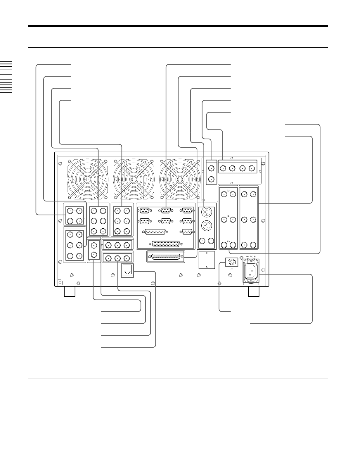
2-3 Connector Panel
a VIDEO IN (COMPOSITE) connectors
b VIDEO OUT (COMPOSITE) connectors
c AUDIO IN (AES/EBU) connectors
Chapter 2 Names and Functions of Parts
d AUDIO OUT (AES/EBU) connectors
i REMOTE connectors
j AUDIO I/F connector
k MONITOR OUT connectors
l DSK IN connectors
m SDTI CP connectors
n SDI IN connectors
o SDI OUT connectors
VIDEO IN (COMPOSITE)
IN –––––––– R1 –––––––– OUT
IN –––––––– R2 –––––––– OUT
VIDEO OUT (COMPOSITE)
A ––––––– P1 ––––––– B
A ––––––– P2 ––––––– B
AUDIO IN (AES/EBU)
CH1/2 ––––––– R1 ––––––– CH3/4
CH1/2 ––––––– R2 ––––––– CH3/4
CH1/2 ––––––– R3 ––––––– CH3/4
REFERENCE
IN
AUDIO OUT (AES/EBU)
CH1/2 ––––––– P1 ––––––– CH3/4
CH1/2 ––––––– P2 ––––––– CH3/4
CH1/2 ––––––– P3 ––––––– CH3/4
TIME CODE IN
R2R1 SYSTEM
IN1(R1)
IN3(R2/P3)
VIDEO CONTROL
IN2(P1)
IN4(R3/P2)
REMOTE PARALLEL I/O(50P)
IN/OUT1(VTR)
IN/OUT2(VTR)
SPARE
MONITOR OUTREMOTE
L
R
ANALOG
COMPOSITE
(SUPER)
DSK IN
VIDEO
KEY
SDI
(SUPER)
SDI IN
A ––––– R1 ––––– B
A ––––– R2 ––––– B
A ––––– R3 ––––– B
SDTI CP
MONITOR OUTIN OUT
12
SDI OUT
A ––––– P1 ––––– B
A ––––– P2 ––––– B
A ––––– P3 ––––– B
A ––––––– P3 ––––––– B
OUT
e REFERENCE connectors
f TIME CODE IN connectors
g TIME CODE OUT connectors
h ETHERNET connector
TIME CODE OUT
P2P1 P3
ETHER
AUDIO I/F
Connector panel
- AC IN connector
q
p Ground terminal
2-8 (E) 2-3 Connector Panel
Page 23

a VIDEO IN (COMPOSITE) connectors (BNC
type)
Input composite video signals (when the BKMA-513
option is installed). The connectors provide a loopthrough connection. A maximum of two inputs are
possible.
b VIDEO OUT (COMPOSITE) connectors (BNC
type)
Output composite video signals (when the BKMA513 option is installed). A maximum of two outputs
are possible.
c AUDIO IN (AES/EBU Digital Audio Input)
connectors (BNC type)
These jacks input digital audio signals in the AES/
EBU format. Up to three inputs can be supported.
d AUDIO OUT (AES/EBU) connectors (BNC
type)
These jacks output digital audio signals in the AES/
EBU format. Up to three outputs can be supported.
e REFERENCE connectors (BNC type)
Input a reference video signal. This may be a video
signal with chrominance burst (VBS) or a
monochrome video signal (VS).
The connectors provide a loop-through connection.
f TIME CODE IN (Time Code Input) connectors
(BNC type)
This is the input jack that is used when recording time
codes from an external device. This jack connects to
the time code output jack on the external device.
The setting that indicates which of the inputs, either
SYSTEM or R1 (R2), in each recording port is to be
used for time code recording is make in the “LTC
SELECT” expansion menu item (menu 670, 671).
(However, when the configuration is 3 input/1 output,
SYSTEM is always used at the R3 port.)
Note
h ETHERNET1) (10BaseT) connector
In order to control the MAV-555SS from an external
device that is connected via Ethernet, connect this
connector to the external device with an Ethernet
cable.
When using a LAN cable: For safety, do not connect
to the connector for peripheral device wiring that
might have excessive voltage.
1)
Ethernet is a registered trademark of the XEROX
Corporation.
i REMOTE (Remote Control Input/Output)
Connectors
REMOTE IN connector (R1, P1, R2/P3, R3/P2,
SPARE)
When controlling the MAV-555SS through an
external device, use the 9-pin remote control cable to
connect this connector to the external device.
REMOTE IN/OUT connector (1, 2)
When controlling an external device from the MAV555SS, use the 9-pin remote control cable to connect
the external device to this connector.
VIDEO CONTROL connector (D-SUB 25 pins)
When controlling the internal digital video processor
from a remote location, connect the HD digital video
controller HKDV-503/900 (sold separately) to this
connector.
For details, refer to the installation manual.
REMOTE PARALLEL I/O connector (D-SUB
50 pins)
The remote control signals from an external device
are connected to this connector.
For details, refer to the installation manual.
j AUDIO I/F connector
Connect to the optional BKMA-570 Analog Audio
Expansion Unit.
For information on the BKMA-570 connectors, refer to Section
2-4, “Analog Audio Expansion Box BKMA-570” (page 2-11).
Chapter 2 Names and Functions of Parts
The TIME CODE IN (SYSTEM) jack supports only
a 1× time code signal. The error message “TM
Warning LTC” appears if any other signal is input.
g TIME CODE OUT connectors (BNC type)
These connectors output playback time codes.
k MONITOR OUT connectors (BNC type, XLR-
3-31)
Output video and audio monitor signals for the port
currently selected on the front panel. The XLR
connectors (L/R) output the audio monitor signal, and
the SDI and ANALOG connectors output a video
signal including superimposed information.
Audio monitor output connectors
There are two audio outputs, L and R. The channels
output are selected with the meter panel’s MONITOR
SELECT buttons and AUDIO INPUT/MONITOR
SELECT buttons.
2-3 Connector Panel 2-9 (E)
Page 24

SDI (SUPER) connector
This outputs a serial digital video/audio signal.
The audio output signals output by this connector are
as follows:
CH1: Audio monitor output. Same as the Lch
signal.
CH2: Audio monitor output. Same as the Rch
signal.
CH3: No output
CH4: No output
Chapter 2 Names and Functions of Parts
If the CHARACTER switch on the system setup
panel is set to ON, timecode information and menu
settings appear as text superimposed on the video
signal.
ANALOG (COMPOSITE) (SUPER) connector
This outputs an analog composite video signal.
If the CHARACTER switch on the system setup
panel is set to ON, timecode information and menu
settings appear as text superimposed on the video
signal.
l DSK IN connectors
When the optional BKMA-560 is installed, the DSK
VIDEO signal is input to the VIDEO connector and
the DSK KEY single is input to the KEY connector.
m SDTI CP connectors
These connectors cannot be used.
n SDI IN (Serial Video/Audio Input) connectors
(BNC type)
The left jack inputs serial digital video/audio signals.
When the power is on, signals that are input to the
jack on the right is output through an internal circuit,
making a bridge connection possible in SD mode.
A maximum of three inputs are available.
o SDI OUT (Serial Video/Audio Input)
connectors (BNC type)
These jacks output serial digital video/audio signals.
A maximum of three outputs are available.
p Ground terminal
Connect to ground as required.
q - AC IN connector
Connect to a power outlet using the power cord (1776-997-11) (sold separately).
2-10 (E) 2-3 Connector Panel
Page 25
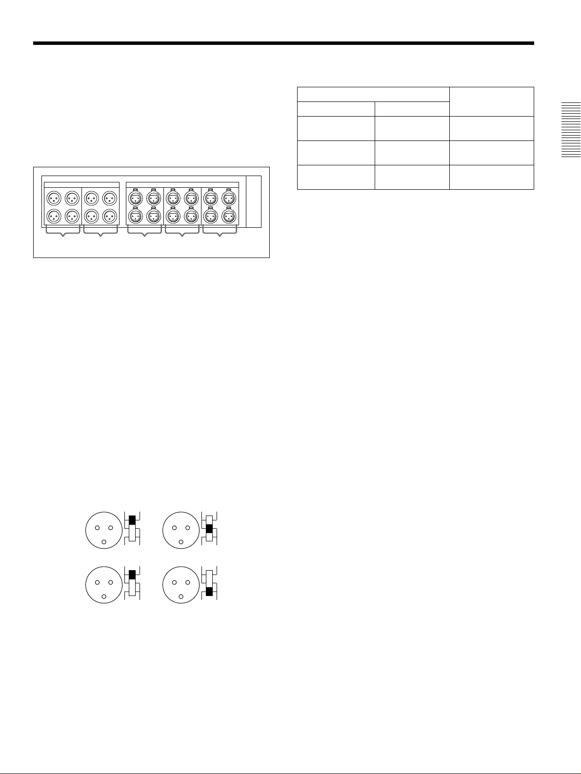
2-4 Analog Audio Expansion Box BKMA-570
When using analog audio input and output with this unit,
connect the optional Analog Audio Expansion Box
BKMA-570 to the AUDIO I/F connectors on the unit’s
connector panel, then connect to peripheral units via the
BKMA-570.
The optional BKMA-513 is necessary for analog input and
output.
INPUT
13212
ab cde
OUTPUT
a INPUT 1 (R1 input) connectors (XLR-3-31)
Analog audio inputs to the R1 port.
b INPUT 2 (R2 input) connectors (XLR-3-31)
Analog audio inputs to the R2 port.
-60 dBu
(microphone input)
+4 dBu (line voice
input)
+4 dBu (line voice
input)
Audio Input
Level Impedance
High impedance
(approx. 20 kΩ)
High impedance
(approx. 20 kΩ)
600 Ω HIGH-ON (upper
Switch Setting
LOW-OFF (lower
position)
HIGH-OFF (central
position)
position)
Chapter 2 Names and Functions of Parts
c OUTPUT 1 (P1 output) connectors (XLR-3-32)
Analog audio outputs from the P1 port.
d OUTPUT 2 (P2 output) connectors (XLR-3-32)
Analog audio outputs from the P2 port.
e OUTPUT 3 (P3 output) connectors (XLR-3-32)
Analog audio outputs from the P3 port. (Planned for
use with future functions.)
Input connectors (a and b) have LEVEL switches for
each channel as shown below.
Channel LEVEL switches are set for use as follows:
CH1
CH3
HIGH ON
LOW OFF
LEVEL 600Ω
HIGH ON
LOW OFF
LEVEL 600Ω
CH2
CH4
HIGH ON
LOW OFF
LEVEL 600Ω
HIGH ON
LOW OFF
LEVEL 600Ω
2-4 Analog Audio Expansion Box BKMA-570 2-11 (E)
Page 26

Page 27

Chapter 3 Preparations
3-1 MAV-555SS Modes
Before using the unit, you need to select a mode according to how you want to
use the MAV-555SS. The available modes are described below.
Motion modes (Two modes)
The motion modes allow you to select the MAV-555SS playback and recording
speeds. When you want to record/playback at standard speed, select the SD mode
(Standard Motion mode). When you want to record/playback at 3 times speed,
select the SS mode (Sony Super Motion mode).
• SS mode: The MAV-555SS can simultaneously record signals
• SD mode: This is the mode to use under normal recording or
Chapter 3 Preparations
input from Sony Super Motion or Philips cameras and
perform playback at -3/3 to 3/3 speed.
In SS mode, you can only use the Panel and DTR+Panel
operation modes. For details, see “Operation modes”
below.
playback conditions. It allows you to edit material
recorded in SS mode and to play back such material at 1/
3 speed. In SD mode, you can use all four operation
modes. For details, see “Operation modes” below.
Operation modes (Four modes)
The operation modes allow you to select how the MAV-555SS is controlled.
There are four modes to select from.
• Panel mode: This mode allows you to control the MAV-555SS from
the optional BKMA-505 Control Panel, Player port on
the editor, or an external device.
• DTR+Panel mode: Replay and slow motion playback using one camera
(Replay & Slow 1).
• DTR+DTR mode: Replay and slow motion playback using two cameras
(Replay & Slow 2).
• BVE mode: The MAV-555SS is used as a recorder VTR.
This section contains examples of system configurations for each mode, as well
as required option settings.
Select the motion mode from Basic menu item 042 PORT CONFIGURATION. Select the
operation mode from Basic menu item 019 SYSTEM OPERATE CONFIGURATION. For
details about the Basic menu, see Section 3-4, “Setup” (page 3-18).
For details about how to connect external devices according to the mode, see Section 3-2,
“Connecting External Devices” (page 3-10).
3-1 MAV-555SS Modes 3-1 (E)
Page 28
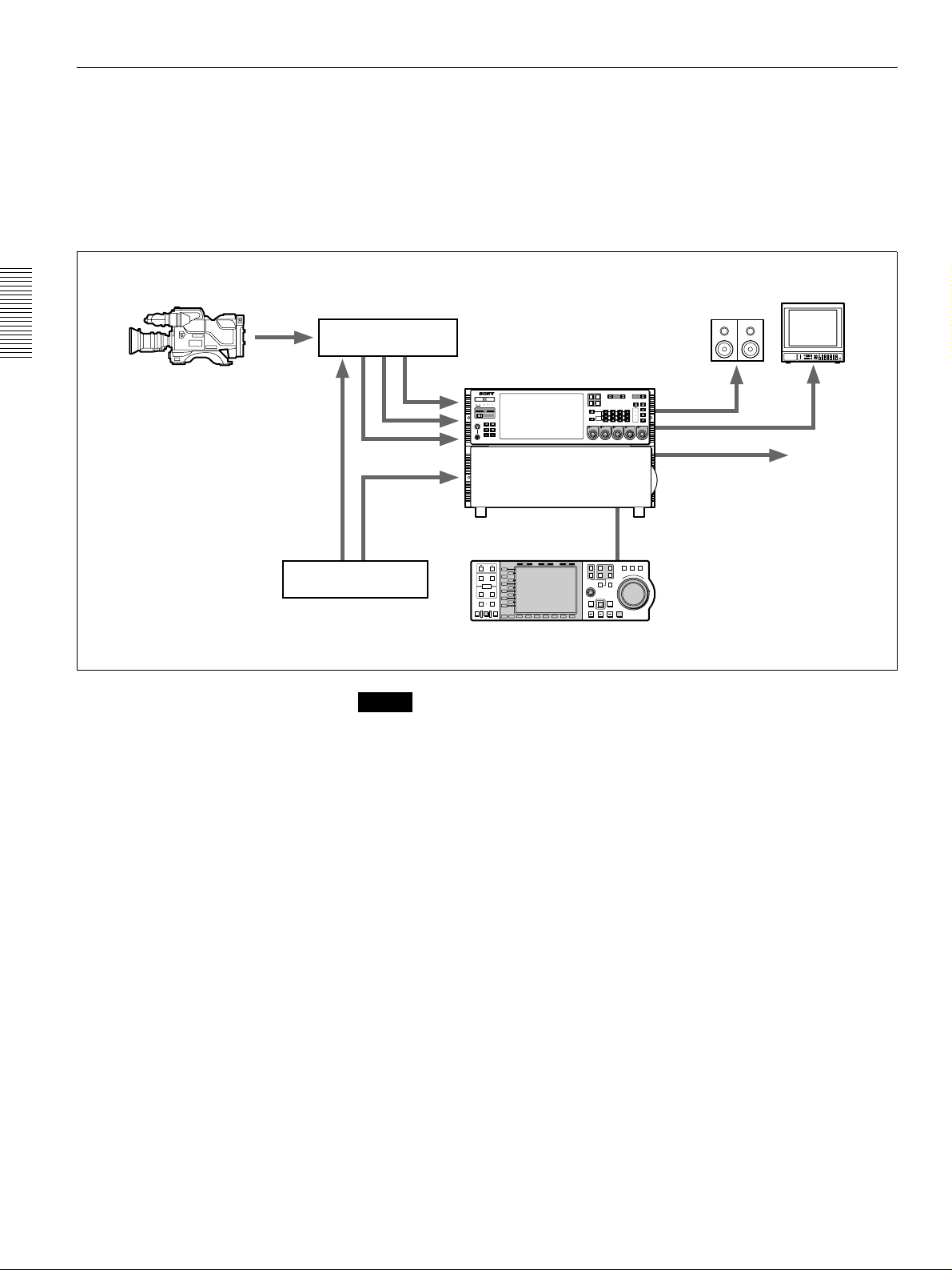
Chapter 3 Preparations
Panel Mode
SS Mode (Sony Super Motion Mode)
Camera Control Unit
CCU-900 + BKP-9330
Sony Super Motion
Camera system
BVP-9500WS + CA950
REF
In this mode you can record input signals from Sony Super Motion and Philips
cameras, and perform playback simultaneously. This mode allows you to select
the Panel and DTR+Panel operation modes.
The following illustration shows a three SDI input and one SDI Super Motion
output system form a BVP-9500WS System (Sony Digital Super Motion Camera
System) connected to the MAV-555SS.
Monitor
COMPOSITE SDI
VIDEO
R1
P1
REMOTE
INPUT
PORT SELECT
PROCESS
CONTROL
P2
SDI
AES/EBU
L
ANALOG
R
AUDIO INPUT / MONITOR SELECT
CH1
CH2 CH3 CH4
CH2
PRESET
VIDEO
CHROMA
REMOTE
SET UP/BLACK
MENU
CHROMA/PHASE
LOCAL
CH4
PRESET
VIDEO/MENU
PRESET
monitor output
CH3
PRESET
R2/
P3
INPUT
MONITOR
CH1
PRESET
SDI/Composite output
SETUP
PANEL SELECT CHARACTER
SELECT
NONE OFF ON80TH
1 2 3
SDI x 3
REF
525
PHONES
0
METER
PANEL
625
SYSTEM HDD
10
CONTROL
PANEL
SETUP BANK
123
HELP
TOTAL /
FULL /
REMAIN
TIME
TC/UB TC TYPE
MENU
SET
CONTROL PANEL
REAR FRONT
MAV-555SS
HOLD RESET TC/UB TC TYPE
Sync Generator
PB EE PB
TRIM
L1
L2
IN OUT
L3
AUDIO
L4
ENTRY
L5
L6
IN
OUT
L7
L8
L9
DMC EDIT
DELETE
L10
MEMORY
L11
PREVIEW
AUTO EDIT
REVIEW
B1 B2 B3 B4 B5 B6 B7
MODE SHIFT
1
R1
PORT SELECT
EXT
R2/
2
P3
PLAYER
MULTI
CONTROL
REC
PREROLL EDIT
REW PLAY F. FWD STOP
SHUTTLE
JOG VAR
P1
P2
F
O
E
S
R
RECORDER
R
W
E
A
V
R
E
D
R
Control Panel
BKMA-505
Note
• In SS mode, set the MAV-555SS expansion menu OUTPUT REF LOCK (menu
120) to REF, and REFFERENCE SELECT (menus 349, 350, 351) to output ref.
• In SS mode, it is necessary to adjust the MAV setting of the Camera Control
Unit (CCU-900). For details about this setting, refer to the CCU-900
Installation Manual, section 1-5-4, “VPR-57 Board (BKP-9330)”.
3-2 (E) 3-1 MAV-555SS Modes
Page 29
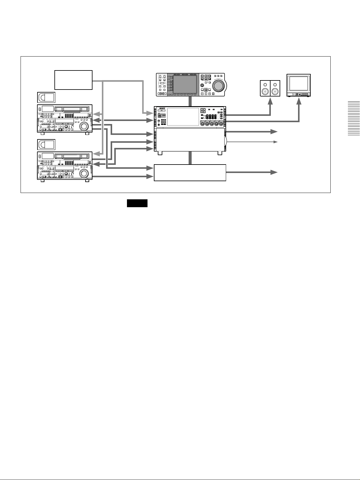
SD Mode (Standard Motion mode)
Sync Generator
REF. REF.
RS 422
VTR
REF.
SDI/Composite
In this mode, the input and output ports are controlled independently from the
optional BKMA-505 Control Panel or from the Player port of the editor.
However, an external device cannot be selected as the recorder.
Control Panel
RS 422
BKMA-505
HOLD RESET TC/UB TC TYPE
PB EE PB
TRIM
L1
L2
IN OUT
L3
AUDIO
L4
ENTRY
L5
L6
IN
OUT
L7
L8
L9
DMC EDIT
DELETE
L10
MEMORY
L11
PREVIEW
AUTO EDIT
REVIEW
B1 B2 B3 B4 B5 B6 B7
MODE SHIFT
METER
CONTROL
PANEL
PANEL
SETUP BANK
525
625
123
SYSTEM HDD
HELP
TOTAL /
FULL /
REMAIN
FINE
PHONES
TC/UB TC TYPE
10
0
MENU
SET
1
R1
PORT SELECT
EXT
R2/
2
P3
PLAYER
MULTI
CONTROL
REC
PREROLL EDIT
REW PLAY F. FWD STOP
R1
P1
PORT SELECT
R2/
P2
P3
AUDIO INPUT / MONITOR SELECT
INPUT
CH1
SDI
AES/EBU
MONITOR
L
ANALOG
R
CH1
CH2
PRESET
PRESET
RECORDER
COMPOSITE SDI
P1
P2
VIDEO
INPUT
CH2 CH3 CH4
SHUTTLE
JOG VAR
F
O
E
S
R
R
W
E
A
V
R
E
D
R
REMOTE
PROCESS
CONTROL
VIDEO
CHROMA
REMOTE
SET UP/BLACK
MENU
CHROMA/PHASE
LOCAL
CH3
CH4
VIDEO/MENU
PRESET
PRESET
PRESET
monitor
SDI/Composite
CONTROL PANEL
SETUP
PANEL SELECT CHARACTER
REAR FRONT
SELECT
NONE OFFON80TH
1 2 3
LTC
MAV-555SS
Monitor
To VTR or Server
Chapter 3 Preparations
VTR
Analog Audio
Analog Audio Expansion Unit
BKMA-570
Analog Audio
2 input/2 output configuration example
Note
When editing, set expansion REFERENCE SELECT (menu 349, 350, 351) to
“output ref”.
3-1 MAV-555SS Modes 3-3 (E)
Page 30

DTR + Panel Mode
SS Mode
This mode allows a single camera to be used for a live relay, with replay and slowmotion playback during recording.
Chapter 3 Preparations
Sony Super Motion
Camera system
BVP-9500WS + CA950
Slowmotion Controller
Monitor
Camera Control Unit
CCU-900 + BKP-9330
REF
SDI x 3
REF
METER
PANEL
525
SYSTEM HDD
PHONES
0
CONTROL
PANEL
SETUP BANK
625
123
HELP
TOTAL /
REMAIN
TC/UB TC TYPE
10
MENU
RS-422
FULL /
TIME
SET
DTR-3000
or
other controllers
COMPOSITE SDI
VIDEO
R1
P1
INPUT
PORT SELECT
R2/
P2
P3
AUDIO INPUT / MONITOR SELECT
INPUT
CH1
CH2 CH3 CH4
SDI
AES/EBU
MONITOR
L
ANALOG
R
CH1
CH2
PRESET
PRESET
CONTROL PANEL
REAR FRONT
SETUP
SELECT
1 2 3
PANEL SELECT CHARACTER
NONE OFF ON80TH
REMOTE
PROCESS
CONTROL
VIDEO
CHROMA
REMOTE
SET UP/BLACK
MENU
CHROMA/PHASE
LOCAL
CH3
CH4
VIDEO/MENU
PRESET
PRESET
PRESET
monitor output
SDI/Composite output
MAV-555SS
HOLD RESET TC/UB TC TYPE
Sync Generator
PB EE PB
TRIM
L1
L2
IN OUT
L3
AUDIO
L4
ENTRY
L5
L6
IN
OUT
L7
L8
L9
DMC EDIT
DELETE
L10
MEMORY
L11
PREVIEW
AUTO EDIT
REVIEW
B1 B2 B3 B4 B5 B6 B7
MODE SHIFT
1
R1
PORT SELECT
EXT
R2/
2
P3
PLAYER
MULTI
CONTROL
REC
PREROLL EDIT
REW PLAY F. FWD STOP
SHUTTLE
JOG VAR
P1
P2
F
O
E
S
R
RECORDER
R
W
E
A
V
R
E
D
R
Control Panel
BKMA-505
Note
• In SS mode, set the MAV-555SS expansion menu OUTPUT REF LOCK (menu
120) to REF, and REFFERENCE SELECT (menus 349, 350, 351) to output ref.
• In SS mode, it is necessary to adjust the MAV setting of the Camera Control
Unit (CCU-900). For details about this setting, refer to the CCU-900
Installation Manual, section 1-5-4, “VPR-57 Board (BKP-9330)”.
SD Mode
Sync Generator
Video Camera
REF.
SDI/Composite
TRIM
IN OUT
AUDIO
ENTRY
IN
OUT
DMC EDIT
DELETE
MEMORY
PREVIEW
AUTO EDIT
REVIEW
Control Panel
BKMA-505
HOLD RESET TC/UB TC TYPE
PB EE PB
L1
L2
L3
L4
L5
L6
L7
L8
L9
L10
L11
B1 B2 B3 B4 B5 B6 B7
MODE SHIFT
525
PHONES
0
METER
PANEL
625
SYSTEM HDD
10
CONTROL
PREROLL EDIT
CONTROL
PANEL
SETUP BANK
123
HELP
TOTAL /
FULL /
REMAIN
FINE
TC/UB TC TYPE
MENU
SET
Configuration example
SHUTTLE
JOG VAR
1
R1
P1
PORT SELECT
EXT
R2/
2
P2
P3
E
S
PLAYER
RECORDER
R
E
V
MULTI
E
R
REC
REW PLAY F. FWD STOP
RS-422
CONTROL PANEL
REAR FRONT
MAV-555SS
Dynamic Monitor Controller
F
O
R
W
A
R
D
DTR-3000
Monitor
COMPOSITE SDI
VIDEO
R1
P1
REMOTE
INPUT
PORT SELECT
PROCESS
CONTROL
P2
AES/EBU
L
ANALOG
R
AUDIO INPUT / MONITOR SELECT
CH1
SDI
CH2
PRESET
SETUP
SELECT
1 2 3
CH2 CH3 CH4
CH3
PRESET
PANEL SELECT CHARACTER
NONE OFFON80TH
VIDEO
CHROMA
REMOTE
SET UP/BLACK
MENU
CHROMA/PHASE
LOCAL
CH4
VIDEO/MENU
PRESET
PRESET
monitor
SDI/Composite
R2/
P3
INPUT
MONITOR
CH1
PRESET
3-4 (E) 3-1 MAV-555SS Modes
Page 31

This example assumes ports R1 and P1 are controlled from a DTR-3000.
Use the basic menu item LIVE DURATION (menu 034) to set the recording time
for port R1.
For details on basic menu settings and operation sequences, refer to Section 3-4, “Setup” (page
3-18).
When using the BKMA-505 control panel, the following ports can be controlled
through the control panel depending on the settings of the basic menu PORT
CONFIGURATION (menu 042).
2 input/2 output ports R2 and P2 ports
1 input/3 output ports R2 and P3 ports
Notes
• When using a DTR-3000 with this unit, the DTR-3000 version must be
CP:V01.30, VS:V01.20, or later. Further, the unit must be used in the
DISK:INDIVIDUAL mode. For details, please contact the company from
which you purchased the unit.
• To change from another operation mode to this mode, execute the -ALL
ERASE (menu 099) basic menu item and then reboot.
• When the LIVE DURATION time value is changed, or when recording from
the beginning of the recording area, existing material must be erased. Delete the
“LIVE1” material in the Panel mode and reboot to this mode, or reboot after
erasing all material using the -ALL ERASE (menu 099) basic menu item.
• Material recorded in this mode will be erased when this mode is again selected
from the Panel mode.
Chapter 3 Preparations
3-1 MAV-555SS Modes 3-5 (E)
Page 32

DTR + DTR Mode (SD mode only)
This mode allows two cameras to be used for a live relay, with replay and slowmotion playback during recording.
Sync Generator
Dynamic Motion Controller
DTR-3000
Monitor
RS-422
Chapter 3 Preparations
Video Camera
REF.
REF.
COMPOSITE SDI
VIDEO
R1
P1
REMOTE
METER
CONTROL
PANEL
PANEL
SETUP BANK
525
625
REF.
SDI/Composite SDI/Composite
SYSTEM HDD
PHONES
0
123
HELP
TOTAL /
FULL /
REMAIN
FINE
TC/UB TC TYPE
10
MENU
SET
CONTROL PANEL
REAR FRONT
INPUT
PORT SELECT
PROCESS
CONTROL
P2
SDI
AES/EBU
L
ANALOG
R
AUDIO INPUT / MONITOR SELECT
CH1
CH2
PRESET
SETUP
SELECT
1 2 3
CH2 CH3 CH4
CH3
PRESET
PANEL SELECT CHARACTER
NONE OFFON80TH
VIDEO
CHROMA
REMOTE
SET UP/BLACK
MENU
CHROMA/PHASE
LOCAL
CH4
VIDEO/MENU
PRESET
PRESET
monitor
R2/
P3
INPUT
MONITOR
CH1
PRESET
MAV-555SS
RS-422
Dynamic Motion Controller
DTR-3000
Configuration example
In this mode, the two groups of ports R1/P1 and R2/P2 are controlled from two
DTR-3000 units.
Use the basic menu item LIVE DURATION (menu 034) to set the recording time
for ports R1 and R2.
For details on basic menu settings and operation sequences, refer to Section 3-4, “Setup” (page
3-18).
Notes
• When a DTR-3000 is used with this unit, it must be version CP:V01.30,
VS:V01.20 or later, and this unit must be used in the DISK:INDIVIDUAL
mode. For details, please contact the supplier of the unit or your Sony
representative.
• To change from another operation mode to this mode, execute the -ALL
ERASE (menu 099) basic menu item and then reboot.
• When the LIVE DURATION time value is changed, or when recording from
the beginning of the recording area, existing material must be erased. Delete the
“LIVE1” (and “LIVE2”) material in the Panel mode and reboot to this mode,
or reboot after erasing all material using the -ALL ERASE (menu 099) basic
menu item.
• Material recorded in this mode will be erased when this mode is again selected
from the Panel mode.
3-6 (E) 3-1 MAV-555SS Modes
Page 33

BVE Mode (SD mode only)
In BVE mode, editing operations can be performed simultaneously while
recording or playing back footage.
This mode makes nonlinear editing possible when the MAV-555SS and MAV555SS special panel or VTR are connected (1), or linear editing when the MAV555SS and a linear editing device (such as the BVE-600) or a VTR are connected.
Examples of system configurations (1) and (2) are shown below.
(1) 2 input/2 output configuration when the MAV-555SS special panel is connected
Sync Generator
REF
Circuit input
1
1
2 3 4 M
10
9
2
8
7
3
6
5
4
4
3
2
1
0
VTR
10
9
8
7
6
5
4
3
2
1
0
Chapter 3 Preparations
SDI/Composite
MAV-555SS
METER
CONTROL
PANEL
PANEL
SETUP BANK
525
625
123
SYSTEM HDD
HELP
TOTAL /
FULL /
REMAIN
FINE
PHONES
TC/UB TC TYPE
10
0
MENU
SET
COMPOSITE SDI
VIDEO
R1
P1
REMOTE
INPUT
PORT SELECT
PROCESS
CONTROL
P2
SDI
AES/EBU
L
ANALOG
R
AUDIO INPUT / MONITOR SELECT
CH1
CH2 CH3 CH4
CH2
PRESET
VIDEO
CHROMA
REMOTE
SET UP/BLACK
MENU
CHROMA/PHASE
LOCAL
CH3
CH4
VIDEO/MENU
PRESET
PRESET
PRESET
R2/
P3
INPUT
MONITOR
CH1
PRESET
RS-422
CONTROL PANEL
SETUP
PANEL SELECT CHARACTER
REAR FRONT
SELECT
NONE OFFON80TH
1 2 3
Monitor
RS-422
MOUSE/
REVSOFTBORD
PQRS TUV WXYZ !
GHI JKL MNO _ / " @
SCR-C0CTL/TC
, . : ; & # * ?
EJECT
STEP
STILL
REW
STOP
JOG DMCSHIFT ALL STOP
SHTL
EDIT
LASTXCLEAR
ABC
00
-
TRACK BALL
MARK
SPEED
MENU
+
987
< = >
T-SET
-
654
T-TRACK
F/TC
321
DEF ( ) [ ]
RETURN
ENTER
+
STEP
FF
TO MAV D555 I/F 1
RECORDER SEL BACK GROUND
MAV VTR
MEMORY
FILE
DEL
NEW
1 2 3 4
FILE
FILE
EFFECT
CUT DISS WIPE TITLE AUDIO
PORT/FILE ASSIGN
R
P1 P2 BG
STORE +
-
REDO
KNOB
LEVER
INPUT
MIX
10
12
34
LR
9
8
0
-1
7
-4
-6
6
-10
-14
5
-20
-28
4
-40
3
-52
-60
-
2
1
0
UNDO
V A1 A2 A3 A4
TRIM
MARK OUTMARK IN
EXECUTE/
SHIFT
REC
MARK
SPLIT
REPLAY
PREVIEW
F555 I/F
LOC
MAN
SOFINEOF
START
TOTAL
PATT
PRMTR
OUT
SPEED
DUR
SCR
GO TO
STBOF
PLAY
Editing Fader Panel
BKNE-1011
Editing Panel
MAVE-F555
Dial Panel
MAVE-D555
3-1 MAV-555SS Modes 3-7 (E)
Page 34

(2) 2 input/2 output configuration when a linear editing device is connected
Chapter 3 Preparations
Video Camera
Sync Generator
SDI/Composite
REF.
Editing Panel
MAVE-F555
RECORDER SEL BACK GROUND
MAV VTR
MEMORY
FILE
DEL
NEW
1 2 3 4
FILE
FILE
EFFECT
CUT DISS WIPE TITLE AUDIO
PORT/FILE ASSIGN
R
P1 P2 BG
STORE +
-
REDO
UNDO
V A1 A2 A3 A4
TRIM
MARK
MARK OUTMARK IN
SPLIT
REPLAY
EXECUTE/
SHIFT
PREVIEW
REC
METER
CONTROL
PANEL
PANEL
SETUP BANK
525
625
123
SYSTEM HDD
HELP
TOTAL /
FULL /
REMAIN
FINE
PHONES
TC/UB TC TYPE
10
0
MENU
SET
CONTROL PANEL
REAR FRONT
MAV-555SS
Analog Audio Expansion Unit
BKMA-570
Monitor
monitor
COMPOSITE SDI
VIDEO
R1
P1
REMOTE
INPUT
PORT SELECT
R2/
P2
P3
AUDIO INPUT / MONITOR SELECT
INPUT
CH1
CH2 CH3 CH4
SDI
AES/EBU
MONITOR
L
ANALOG
R
CH1
CH2
CH3
CH4
PRESET
PRESET
PRESET
PRESET
Composite
PROCESS
CONTROL
VIDEO
CHROMA
REMOTE
SET UP/BLACK
MENU
CHROMA/PHASE
LOCAL
VIDEO/MENU
RS-422
PRESET
Monitor
monitor
Composite
RS-422
SETUP
PANEL SELECT CHARACTER
SELECT
NONE OFFON80TH
1 2 3
Composite
RS-422
Editing Control Unit
BVE-600
Composite
monitor
Analog audio
VTR
Analog audio
Analog audio
Analog audio
Analog Audio Mixer
MXP-29
Monitor
• In the BVE mode, the Record port (R1) and the Play port (P1) are combined,
so the unit can serve as the VTR of a re-recorder (a combination recording and
playback port is called an RP port). This means that recording at the R2 port
while editing is possible.
• To begin editing, execute the Linear Edit New Material command from the
optional BKMA-505 Control Panel to create a BLACK/MUTING file. This file
is assigned to the RP port. The length of the initial file must be specified by
LINEAR EDIT NEW FILE (menu 321) beforehand.
• When performing four-channel editing with a two-channel audio editor, select
ANALOG AUDIO EDIT PRESET REPLACE (menu 307) on the expansion
menu.
• For two-channel audio editing, use the BKMA-570 Analog Audio Expansion
Unit. If not enough analog audio connectors are available for wiring of the
system, channel 1 and 2 audio can be output from the channel 3 and 4 terminals
by setting 821 AUDIO OUTPUT CHANNEL on setup menu 821.
• In BVE mode, only 2 input/2 output and 1 input/3 output configurations can be
used.
3-8 (E) 3-1 MAV-555SS Modes
Page 35

• Specify the following as the editor VTR constants:
NTSC BLOCK-1
A0 70 00 3C 05 05 00 80
BLOCK-2
0C 04 FE 00 80 3C FF
PA L B LO C K- 1
A1 70 00 3C 05 05 00 80
BLOCK-2
0C 04 FE 00 80 3C FF
Please refer to Section 3-4, “Setup” (page 3-18) for details about setup contents and basic
menu operations.
Notes
• Apply the same reference video signal to the VTR, editor, and the MAV unit,
set MAV-555SS expansion menu OUTPUT REF LOCK (menu 120) to REF
and REFERENCE SELECT (menus 349, 350, 351) to output ref.
Please refer to Section 3-3, “External Synchronization of Output Video Signals” (page 3-17)
and Section 3-4, “Setup” (page 3-18).
• Collection is performed from the controller connected to the R2 port, the
optional control panel (BKMA-505), the editing panel (MAVE-F555), etc.
• File assignments made to the RP port or the P2/P3 port are made from the
optional control panel (BKMA-505), the editing panel (MAVE-F555), etc.
• When configured with an editor that uses analog composite signals, the
optional BKMA-513 AD/DA Converter Board is necessary. When configured
with an analog audio mixer (such as MXP-29), the optional BKMA-570
Analog Audio Expansion Unit is also required.
• In BVE mode, the maximum variable mode playback speed is ±1× normal
speed; you cannot playback at double speed.
Chapter 3 Preparations
3-1 MAV-555SS Modes 3-9 (E)
Page 36

Chapter 3 Preparations
3-2 Connecting External Devices
This section illustrates the connections of this unit to other devices, in the
operation modes described in Section 3-1, “MAV-555SS Modes”.
3-2-1 Connections with the Panel Mode
Connecting to digital devices (SS mode)
The following example illustrates how to connect a Sony BVP-9500WS to the
MAV-555SS.
Note
• To connect an analog VTR you need an optional AD/DA Converter Board
(BKMA-513) and Analog Audio Expansion Unit (BKMA-570).
• The SS-A, SS-B, SS-C, cables must be no longer than 10 meters.
• In SS mode, set the MAV-555SS expansion menu OUTPUT REF LOCK (menu
120) to REF, and REFFERENCE SELECT (menus 349, 350, 351) to output ref.
Sync Generator
VIDEO IN (COMPOSITE)
IN –––––––– R1 –––––––– OUT
IN –––––––– R2 –––––––– OUT
VIDEO OUT (COMPOSITE)
A ––––––– P1 ––––––– B
A ––––––– P2 ––––––– B
A ––––––– P3 ––––––– B
REF IN SDI OUT
SS-A
SS-B
SS-C
Camera control unit
CCU-900
+BKP-9330
or similar
AUDIO IN (AES/EBU)
CH1/2 ––––––– R1 ––––––– CH3/4
CH1/2 ––––––– R2 ––––––– CH3/4
CH1/2 ––––––– R3 ––––––– CH3/4
REFERENCEINTIME CODE IN
OUT
AUDIO OUT (AES/EBU)
CH1/2 ––––––– P1 ––––––– CH3/4
CH1/2 ––––––– P2 ––––––– CH3/4
CH1/2 ––––––– P3 ––––––– CH3/4
TIME CODE OUT
IN1(R1)
IN3(R2/P3)
VIDEO CONTROL
R2R1 SYSTEM
P2P1 P3
ETHER
Analog Audio Expansion Unit
BKMA-570
IN2(P1)
IN4(R3/P2)
REMOTE PARALLEL I/O(50P)
AUDIO I/F
IN
DSK IN
VIDEO
KEY
MONITOR OUTREMOTE
IN/OUT1(VTR)
L
IN/OUT2(VTR)
R
SPARE
ANALOG
COMPOSITE
(SUPER)
(SUPER)
SDI
Video monitor
BVM-series
AUDIO OUT
(when using AES/EBU)
Amplifier
or similar
SDI IN
A ––––– R1 ––––– B
A ––––– R2 ––––– B
A ––––– R3 ––––– B
SDTI CP
MONITOR OUTIN OUT
12
SDI OUT
A ––––– P1 ––––– B
A ––––– P2 ––––– B
A ––––– P3 ––––– B
or similar
Digital VTR
Video server
Video monitor
or similar
SS-A
SS-B
SS-C
Video camera
BVP-9500WS
+CA950
or similar
3-10 (E) 3-2 Connecting External Devices
IN
Page 37

Connecting to digital devices (SD mode)
The following example illustrates connection to a digital VTR, such as one from
the Sony DVW series.
Sync Generator
*1
*2
REF IN AUDIO OUT
(when using AES/EBU)
Digital VTR
DVW-500/510/522 series
DNW-A100/A75/A65 series
DVR-2100 series or similar
VIDEO IN (COMPOSITE)
IN –––––––– R1 –––––––– OUT
IN –––––––– R2 –––––––– OUT
VIDEO OUT (COMPOSITE)
A ––––––– P1 ––––––– B
A ––––––– P2 ––––––– B
A ––––––– P3 ––––––– B
AUDIO IN (AES/EBU)
CH1/2 ––––––– R1 ––––––– CH3/4
CH1/2 ––––––– R2 ––––––– CH3/4
CH1/2 ––––––– R3 ––––––– CH3/4
REFERENCEINTIME CODE IN
OUT
AUDIO OUT (AES/EBU)
CH1/2 ––––––– P1 ––––––– CH3/4
CH1/2 ––––––– P2 ––––––– CH3/4
CH1/2 ––––––– P3 ––––––– CH3/4
TIME CODE OUT
SDI OUT
R2R1 SYSTEM
P2P1 P3
ETHER
IN1(R1)
IN3(R2/P3)
VIDEO CONTROL
REMOTE PARALLEL I/O(50P)
*1
*2
Video monitor
BVM-series or
similar
IN2(P1)
IN4(R3/P2)
AUDIO I/F
IN/OUT1(VTR)
L
IN/OUT2(VTR)
R
SPARE
COMPOSITE
*1 *2
ANALOG
(SUPER)
DSK IN
VIDEO
KEY
MONITOR OUTREMOTE
SDI
(SUPER)
SDI IN
A ––––– R1 ––––– B
A ––––– R2 ––––– B
A ––––– R3 ––––– B
SDTI CP
MONITOR OUTIN OUT
12
SDI OUT
A ––––– P1 ––––– B
A ––––– P2 ––––– B
A ––––– P3 ––––– B
SDI IN
Digital VTR
DVW-500/510/522 series
DNW-A100/A75/A65 series
DVR-2100 series or similar
Chapter 3 Preparations
AUDIO IN
(when using
AES/EBU)
*1 EXT1 connection. However, either can be used as one unit for editing.
*2 EXT2 connection. However, either can be used as one unit for editing.
3-2 Connecting External Devices 3-11 (E)
Page 38

Connecting to analog devices (SD mode)
The following options are required in order to connect an analog VTR to the
MAV-555SS: AD/DA Converter Board BKMA-513 and Analog Audio
Expansion Unit BKMA-570.
Note
When using a 3 input/1 output configuration, the R3 port does not support analog
input.
Chapter 3 Preparations
Sync Generator
REF IN
VIDEO IN (COMPOSITE)
*1
*2
IN –––––––– R1 –––––––– OUT
IN –––––––– R2 –––––––– OUT
VIDEO OUT (COMPOSITE)
A ––––––– P1 ––––––– B
A ––––––– P2 ––––––– B
A ––––––– P3 ––––––– B
AUDIO IN (AES/EBU)
CH1/2 ––––––– R1 ––––––– CH3/4
CH1/2 ––––––– R2 ––––––– CH3/4
CH1/2 ––––––– R3 ––––––– CH3/4
REFERENCEINTIME CODE IN
OUT
COMPOSITE VIDEO OUT
Analog VTR
Betacam SP VTR series or
similar
AUDIO OUT (AES/EBU)
CH1/2 ––––––– P1 ––––––– CH3/4
CH1/2 ––––––– P2 ––––––– CH3/4
CH1/2 ––––––– P3 ––––––– CH3/4
R2R1 SYSTEM
TIME CODE OUT
P2P1 P3
ETHER
IN1(R1)
IN3(R2/P3)
VIDEO CONTROL
IN2(P1)
IN4(R3/P2)
REMOTE PARALLEL I/O(50P)
AUDIO I/F
IN/OUT1(VTR)
L
IN/OUT2(VTR)
R
SPARE
ANALOG
COMPOSITE
(SUPER)
*1 *2
Video monitor
BVM-series or
similar
DSK IN
VIDEO
KEY
MONITOR OUTREMOTE
SDI
(SUPER)
SDI IN
A ––––– R1 ––––– B
A ––––– R2 ––––– B
A ––––– R3 ––––– B
SDTI CP
MONITOR OUTIN OUT
12
SDI OUT
A ––––– P1 ––––– B
A ––––– P2 ––––– B
A ––––– P3 ––––– B
COMPOSITE VIDEO IN
ANALOG AUDIO OUT
Analog VTR
Betacam SP VTR series or
similar
*1 EXT1 connection. However, either can be used as one unit for editing.
*2 EXT2 connection. However, either can be used as one unit for editing.
Analog Audio Expansion Unit
BKMA-570
*1 *2
IN OUT
ANALOG AUDIO IN
3-12 (E) 3-2 Connecting External Devices
Page 39

3-2-2 Connections with the DTR + Panel Mode
Connecting with the DTR+Panel mode (SS mode)
The following example illustrates how to connect a Sony BVP-9500WS to the
MAV-555SS.
Note
• To connect an analog VTR you need an optional AD/DA Converter Board
(BKMA-513) and Analog Audio Expansion Unit (BKMA-570).
• The SS-A, SS-B, SS-C cables must be no longer than 10 meters.
• In SS mode, set the MAV-555SS expansion menu OUTPUT REF LOCK (menu
120) to REF, and REFFERENCE SELECT (menus 349, 350, 351) to output ref.
Sync Generator
VIDEO IN (COMPOSITE)
IN –––––––– R1 –––––––– OUT
IN –––––––– R2 –––––––– OUT
VIDEO OUT (COMPOSITE)
A ––––––– P1 ––––––– B
A ––––––– P2 ––––––– B
A ––––––– P3 ––––––– B
AUDIO IN (AES/EBU)
CH1/2 ––––––– R1 ––––––– CH3/4
CH1/2 ––––––– R2 ––––––– CH3/4
CH1/2 ––––––– R3 ––––––– CH3/4
REFERENCEINTIME CODE IN
OUT
AUDIO OUT (AES/EBU)
CH1/2 ––––––– P1 ––––––– CH3/4
CH1/2 ––––––– P2 ––––––– CH3/4
CH1/2 ––––––– P3 ––––––– CH3/4
TIME CODE OUT
R2R1 SYSTEM
P2P1 P3
ETHER
IN1(R1)
IN3(R2/P3)
VIDEO CONTROL
IN2(P1)
IN4(R3/P2)
REMOTE PARALLEL I/O(50P)
AUDIO I/F
IN/OUT1(VTR)
IN/OUT2(VTR)
SPARE
L
R
ANALOG
COMPOSITE
(SUPER)
DSK IN
VIDEO
KEY
MONITOR OUTREMOTE
SDI
(SUPER)
Dynamic Motion
Controller
DTR-3000
SDTI CP
MONITOR OUTIN OUT
12
SDI OUT
SDI IN
A ––––– P1 ––––– B
A ––––– R1 ––––– B
A ––––– P2 ––––– B
A ––––– R2 ––––– B
A ––––– P3 ––––– B
A ––––– R3 ––––– B
Chapter 3 Preparations
Digital VTR
Video server
Video monitor
or similar
SS-A
SS-B
SS-C
REF IN SDI OUT
SS-A
SS-B
SS-C
Camera control unit
CCU-900
+BKP-9330
or similar
Video camera
BVP-9500WS
+CA950
or similar
Analog Audio Expansion Unit
BKMA-570
IN
Amplifier
Video monitor
BVM-series
or similar
AUDIO OUT
(when using AES/EBU)
or similar
IN
3-2 Connecting External Devices 3-13 (E)
Page 40

Connecting with the DTR+Panel mode (SD mode)
Chapter 3 Preparations
Sync Generator
VIDEO IN (COMPOSITE)
IN –––––––– R1 –––––––– OUT
IN –––––––– R2 –––––––– OUT
VIDEO OUT (COMPOSITE)
A ––––––– P1 ––––––– B
A ––––––– P2 ––––––– B
A ––––––– P3 ––––––– B
AUDIO IN (AES/EBU)
CH1/2 ––––––– R1 ––––––– CH3/4
CH1/2 ––––––– R2 ––––––– CH3/4
CH1/2 ––––––– R3 ––––––– CH3/4
REFERENCEINTIME CODE IN
OUT
AUDIO OUT (AES/EBU)
CH1/2 ––––––– P1 ––––––– CH3/4
CH1/2 ––––––– P2 ––––––– CH3/4
CH1/2 ––––––– P3 ––––––– CH3/4
TIME CODE OUT
R2R1 SYSTEM
P2P1 P3
ETHER
IN1(R1)
IN3(R2/P3)
VIDEO CONTROL
IN2(P1)
IN4(R3/P2)
REMOTE PARALLEL I/O(50P)
AUDIO I/F
IN/OUT1(VTR)
IN/OUT2(VTR)
SPARE
L
R
ANALOG
COMPOSITE
(SUPER)
Dynamic Motion
Controller
DTR-3000
DSK IN
VIDEO
KEY
MONITOR OUTREMOTE
SDI
(SUPER)
SDI IN
A ––––– R1 ––––– B
A ––––– R2 ––––– B
A ––––– R3 ––––– B
SDTI CP
MONITOR OUTIN OUT
12
SDI OUT
A ––––– P1 ––––– B
A ––––– P2 ––––– B
A ––––– P3 ––––– B
REF IN SDI OUT
Video camera
BVP-900
BVP-950
or similar
Video monitor
BVM-series
or similar
Digital VTR
Video server
Video monitor
or similar
3-14 (E) 3-2 Connecting External Devices
Page 41

3-2-3 Connections with the DTR + DTR Mode
Sync Generator
Dynamic Motion
Controller
DTR-3000
REF IN
VIDEO IN (COMPOSITE)
IN –––––––– R1 –––––––– OUT
IN –––––––– R2 –––––––– OUT
VIDEO OUT (COMPOSITE)
A ––––––– P1 ––––––– B
A ––––––– P2 ––––––– B
A ––––––– P3 ––––––– B
Video camera
BVP-900
BVP-950
or similar
AUDIO IN (AES/EBU)
CH1/2 ––––––– R1 ––––––– CH3/4
CH1/2 ––––––– R2 ––––––– CH3/4
CH1/2 ––––––– R3 ––––––– CH3/4
REFERENCEINTIME CODE IN
OUT
AUDIO OUT (AES/EBU)
CH1/2 ––––––– P1 ––––––– CH3/4
CH1/2 ––––––– P2 ––––––– CH3/4
CH1/2 ––––––– P3 ––––––– CH3/4
TIME CODE OUT
R2R1 SYSTEM
P2P1 P3
ETHER
IN1(R1)
IN3(R2/P3)
VIDEO CONTROL
IN2(P1)
IN4(R3/P2)
REMOTE PARALLEL I/O(50P)
AUDIO I/F
IN/OUT1(VTR)
IN/OUT2(VTR)
SPARE
MONITOR OUTREMOTE
L
R
ANALOG
COMPOSITE
(SUPER)
DSK IN
VIDEO
KEY
SDI IN
A ––––– R1 ––––– B
SDTI CP
MONITOR OUTIN OUT
12
SDI OUT
A ––––– P1 ––––– B
Chapter 3 Preparations
Dynamic Motion Controller
DTR-3000
A ––––– P2 ––––– B
A ––––– R2 ––––– B
SDI
(SUPER)
A ––––– R3 ––––– B
A ––––– P3 ––––– B
Digital VTR
Video server
Video monitor
or similar
REF IN
Video camera
BVP-900
BVP-950
or similar
Video monitor
BVM-series
or similar
3-2 Connecting External Devices 3-15 (E)
Page 42

3-2-4 BVE Mode Connections
Sync Generator
Analog VTR
REF IN
(Betacam SP or similar)
Chapter 3 Preparations
VIDEO IN (COMPOSITE)
IN –––––––– R1 –––––––– OUT
IN –––––––– R2 –––––––– OUT
VIDEO OUT (COMPOSITE)
A ––––––– P1 ––––––– B
A ––––––– P2 ––––––– B
A ––––––– P3 ––––––– B
REF IN
AUDIO IN (AES/EBU)
CH1/2 ––––––– R1 ––––––– CH3/4
CH1/2 ––––––– R2 ––––––– CH3/4
CH1/2 ––––––– R3 ––––––– CH3/4
REFERENCEINTIME CODE IN
OUT
AUDIO OUT (AES/EBU)
CH1/2 ––––––– P1 ––––––– CH3/4
CH1/2 ––––––– P2 ––––––– CH3/4
CH1/2 ––––––– P3 ––––––– CH3/4
TIME CODE OUT
Analog VTR
Betacam SP VTR
Series or similar
R2R1 SYSTEM
P2P1 P3
ETHER
MONITOR
IN1(R1)
IN3(R2/P3)
IN2(P1)
IN4(R3/P2)
VIDEO CONTROL
REMOTE PARALLEL I/O(50P)
AUDIO I/F
ANALOG AUDIO OUT
DSK IN
VIDEO
KEY
MONITOR OUTREMOTE
IN/OUT1(VTR)
L
IN/OUT2(VTR)
R
SPARE
ANALOG
COMPOSITE
(SUPER)
(SUPER)
SDI
Editing Panel
MAVE-F555
Video Monitor
BVM Series or similar
SDI IN
A ––––– R1 ––––– B
A ––––– R2 ––––– B
A ––––– R3 ––––– B
SDTI CP
MONITOR OUTIN OUT
12
SDI OUT
A ––––– P1 ––––– B
A ––––– P2 ––––– B
A ––––– P3 ––––– B
Video Monitor
BVM Series or similar
Analog Audio Expansion Unit
BKMA-570
REMOTE IN
RECORDER MONITOR IN
VIDEO OUT
COMPOSITE VIDEO IN PLAYER 1
R REMOTE
P1 REMOTE
Editing Control Unit BVE-600
REF IN
When configured with an editor that uses analog composite signals, 2 each of the
optional BKMA-513 AD/DA Converter Board is required. When configured with
an analog audio mixer (such as MXP-29), the optional BKMA-570 Analog Audio
Expansion Unit is also required.
3-16 (E) 3-2 Connecting External Devices
P2 REMOTE
Note
Video Monitor
BVM Series or similar
ANALOG COMPOSITE OUT
COMPOSITE VIDEO IN PLAYER 2
SPEAKER
MONITOR OUT
MIXER
REMOTE EDITOR
MONITOR
OUT
ANALOG OUT 1
P2 MIC/LINE IN
ANALOG OUT 2
R MONITOR IN
Analog Audio Mixer
MXP-29
P1 MIC/LINE IN
ANALOG IN 1
LINE OUT
Page 43

3-3 External Synchronization of Output Video Signals
Output image signals are synchronized with either the reference video signal
input to the REF.IN connector, or the video signal input to R1 and R2. External
synchronization varies as follows according to the settings of Expansion menu
item OUTPUT REF LOCK (menu 120).
Start
No
No external
synchronization
Is a signal input to the
connector selected by the
R1 VIDEO INPUT
SELECT switch?
Synchronization to reference
video signal input to
R1 video input connector
No
No external
synchronization
Setting of Expansion
menu item 120?
R2
Is a signal input to the
connector selected by the
R2 VIDEO INPUT
SELECT switch?
Ye sYe s
Synchronization to reference
video signal input to
R2 video input connector
REFR1
No
No external
synchronization
Chapter 3 Preparations
Is a signal input
to the REF. VIDEO
INPUT connector?
Ye s
Synchronization to reference
video signal input to
REF. INPUT connector
Note
In SS mode, set the MAV-555SS expansion menu OUTPUT REF LOCK (menu
120) to REF.
3-3 External Synchronization of Output Video Signals 3-17 (E)
Page 44

3-4 Setup
Chapter 3 Preparations
Carry out the principal settings required before using this
unit by menu operations.
The setup menus on this unit consist of the Basic menu and
the Expansion menu, and these menus include the
following items.
• Basic menu............Application selection, content and
position of superimposed text
information, 525 (NTSC) or 625
(PAL) selection, HDD and RAID
settings, bit rate selection, and other
settings.
• Expansion menu....REC INHIBIT settings for
individual ports, audio/video
control, and other settings.
Settings made in the Basic and Expansion menus can be
saved on a memory card (sold separately) and read as
required. All banks (bank 1 to bank 3) can be saved at
once, or each bank can be saved and read separately. Up to
10 banks can be saved or read.
The following memory cards (sold separately) can be
used:
Supported format
ATA flash card: PCMCIA 2.0 (JEIDA 4.1), PCMCIA
ATA 1.02, Type 2-compatible
Capacity: 8 MB or higher
Recommended product: “MemoryStick” + adapter
MSA-8AN (8 MB) “MemoryStick”
MSAC-PC2N PC card adapter
Note
Data recorded with the MAV-555/555A is incompatible
with the MAV-555SS, and vice-versa.
This section lists the contents of the menus, and describes
how to make settings.
3-4-1 Basic Menu Settings
How to Read the Tables
• In the “Settings” column, values enclosed in squares are
defaults.
About the Display
• The monitor screen and time data display on the front
panel show the item number, the item name, and the
setting value.
• The upper and lower dots of the colon displayed
between the item number and name may either flash or
remain lit, indicating the following conditions.
Upper dot
002:CHAR H-POS
Lower dot
(1) Items that take effect immediately or items that take
effect after the system has been rebooted. For items
that take effect immediately, the lower colon dot
lights up, and for items that take effect after
rebooting, the dot flashes.
(2) Items that can be set for each bank or items with a
common setting for all banks. When items can be set
for each bank, the upper colon dot lights up, and when
items have a common setting for all banks, the dot
flashes.
Example: indicates an item that can
• On the font panel display, the upper dot is displayed
alone to indicate items that can be set for each bank and
which become effective upon rebooting. On the monitor
screen, this is indicated by a dot displayed in the center.
• The letters ‘B’ and ‘I’ appear at the upper right of the
setup menu on the monitor screen. ‘B’ indicates that the
selected setting item can be set for each BANK
independently, and ‘I’ indicates that the selected setting
takes effect immediately.
• The distinction between “B” and “I” is also indicated in
the “Item number” column.
Note
If the power is turned off while the menu is open, please
note that changes made nonetheless become effective.
002:CHAR H-POS
010 -525/625
be set independently for
each bank, which setting
takes effect immediately.
indicates an item that has a
common setting for all
banks, which setting takes
effect only after rebooting.
3-18 (E) 3-4 Setup
Page 45

Basic menu items
Item number Display indication Settings
001
002 *
PREROLL TIME This item sets the pre-roll time when performing editing from the BKMA-505.
BI
0 .. .. 15 seconds
5
CHARACTER H-POSITION Set the horizontal position of timecode and other superimposed text information output
BI
from the MONITOR OUT terminals of the SDI (SUPER) and ANALOG COMPOSITE
(SUPER) terminals. The value 00 .. .. 31:00 corresponds to the distance from the left
edge of the screen: incrementing the value by one moves the displayed text one character
position to the right.
003 *
CHARACTER V-POSITION Set the vertical position of timecode and other superimposed text information output
BI
from the MONITOR OUT terminals of the SDI (SUPER) and ANALOG COMPOSITE
(SUPER) terminals. The value 00 .. .. 12:00 corresponds to the distance from the top
edge of the screen: incrementing the value by one moves the displayed text down one
line.
005
DISPLAY INFORMATION
BI
SELECT
Select the information superimposed on the output from the SDI (SUPER) and
ANALOG COMPOSITE (SUPER) connectors when the CHARACTER switch on the
system setup panel is set to ON.
time & stat
: Time data information and operating status
time & UB : Time data information and user bits
time only : Time data only
time & TM1: Time data information and TM1
time & TM2: Time data information and TM2
006
LOCAL FUNCTION ENABLE Select which buttons on the control panel of this unit can be operated when being
BI
remotely controlled by another device.
all disable
: All buttons and switches are disabled.
stop : Only the STOP button operates.
all enable : All controls operate.
007
008
POSTROLL TIME This item sets the post-roll time when performing editing from the BKMA-505.
BI
ANALOG MONITOR
BI
SUPERIMPOSE
0 .. .. 15 seconds
5
Sets the control method for superimpose data output for MONITOR OUT of ANALOG
COMPOSITE.
switch
: Switches the CHARACTER SW on/off.
inhibit : Normally not output.
009 *
CHARACTER TYPE Select the character style of the information superimposed on the output from the SDI
BI
(SUPER) and ANALOG COMPOSITE (SUPER) connectors.
white
: White characters on black background
black : Black characters on white background
W/out : White characters with black outline
B/out : Black characters with white outline
010 – 525/625 Select the NTSC or PAL standard.
: NTSC
ALL ERASE (menu 099).
: Normal
011 *
SUB MENU
EXECUTE
525/60
625/50 : PAL
Note: After changing the settings for this item, all material must be erased using -
525/625
CHARACTER V-SIZE Set the height of timecode and other information superimposed on the output from the
BI
SDI (SUPER) and ANALOG COMPOSITE (SUPER) connectors.
X1
X2 : Double height
012 DROP FRAME MODE (WITH
525 OPERATION ONLY)
Select the timecode generator operating mode.
DF
: Drop-frame mode
NDF : Non-drop-frame mode
Note: After changing the settings for this item, all material must be erased using -
ALL ERASE (menu 099).
* When setting items 002, 003, 009 and 011, watch the monitor to obtain the desired
condition. (However, if the setting differs from the currently running SETUP BANK,
the location of the character data on the monitor will not change.
16
10
Chapter 3 Preparations
3-4 Setup 3-19 (E)
Page 46

Chapter 3 Preparations
Basic menu items (Continued)
Item number Display indication Settings
013
014
015
016
019 SYSTEM OPERATE
022
027 – FAST REBOOT Carry out a fast reboot of the system. This is faster than switching the system off and on
028 AUDIO BIT LENGTH Select the word length for audio sampling.
030
PB/EE SELECT P1
PB/EE SELECT P2
PB/EE SELECT P3
BI
CHARACTER POSITION V
SHIFT
BI
CONFIGURATION
ERROR INFORMATION
BI
SELECT
SUB MENU
ERROR/WARNING Specifies whether the ERROR/WARNING display is on or off.
NOT ENOUGH SPACE Specifies whether a warning message is displayed when there remains approximately
I SUB MENU
EXECUTE
GOOD SHOT PARAMETER Specifies the partial save method to use for Replay scenes with the DTR-3000, for
B
SUB MENU
SAVE DUR. (1 .. .. 255) Specifies the partial save duration, in seconds.
TRIM SIZE (0 .. .. 15) Specifies the trim length to be added before and after the partial save period.
AUTO SAVE Specifies the trigger command to start partial saving.
CUEUP SELECT Specifies the time data at which to perform cue up in DTR+PANEL or DTR+DTR
5
5
For the PANEL, DTR+PANEL, DTR+DTR and BVE modes, specifies when the PB port
enters the state indicated by SETUP MENU 108 AUTO EE SELECT, and whether it
should automatically correspond to the REC port.
PB
PB/EE : Switch to the REC side according to the SETUP MENU 108 status.
Note: In the BVE mode, “PB/EE SELECT P2” item (menu 014) is disabled.
The vertical position of text display of time codes output from the MONITOR OUT
terminal, SDI (SUPER) and ANALOG COMPOSITE (SUPER) terminals, can be more
minutely adjusted than is possible with SETUP MENU 003.
0
.. 20
Select the application mode for this unit.
PANEL
DTR + PANEL: Controls R1 and P1 with the DTR-3000, controls R2 and P2 (or P2 and
DTR + DTR : The R1/P1 and R2/P2 pairs are controlled by two DTR-3000 units.
BVE : R1 and P1 are controlled as an RP port by the editor.
Activate or deactivate various status information display output from the MONITOR
OUT connectors of the SDI (SUPER) or ANALOG COMPOSITE (SUPER) connectors.
Note: This setting item takes priority over the system setup panel CHARACTER
on
off
Note: Even if this is set to “on”, the warning message “Ref. Missing” is not
five minutes of recording time on the HDD.
on
off
again, because the HDD power supply is not turned off.
Start : Start reboot.
16 bits
20 bits
Notes: • Bit length cannot be set for individual lots of material.
highlight editing with DTR+Panel and DTR+DTR modes.
off
cue up with data : Start partial save after cue up.
mode.
FTC
timer mode : Cue up is performed according to the timer mode.
Notes: • When using the DISK INDIVIDUAL MODE of the DTR-3000, select
: Always output at the PB side.
: All ports are controlled only from the optional BKMA-505
P3) from the BKMA-505.
switch setting.
displayed.
• After changing the settings for this item, all material must be erased using
-ALL ERASE (menu 099).
: Partial save disabled
: Regardless of the timer mode, cue up is performed with TM2 (FTC).
“FTC”. However, select “timer mode” in the following cases:
- When performing direct cue up in 205 point mode from the keypad.
- When performing cue up in 10 point mode with SERACH + CUEn.
• When using a controller other than the DTR-3000, select “timer mode”. In
this situation it is not possible to use the GOOD SHOT function, so set the
AUTO SAVE item (menu 030) to “off”.
3-20 (E) 3-4 Setup
Page 47

Basic menu items (Continued)
Item number Display indication Settings
030
DTR CUE LIST CLEAR Selects whether to delete the DTR-3000 cue list when files are unloaded.
B
enable
: The cue list is deleted.
disable : The cue list is not deleted.
034 LIVE DURATION In the DTR + Panel or DTR + DTR mode, specify the length reserved for recording.
B SUB MENU
DTR-1 HOUR (0 .. .. 23)
DTR-1 MIN ( 0 .. )
DTR-2 HOUR (0 .. .. 23)
DTR-2 MIN ( 0 .. )
1
59
1
59
DTR-1 settings apply to the R1/P1 pair, and DTR-2 settings apply to the R2/P2 pair.
Notes: This is affected by the VIDEO COMPRESSION RATE and HDD capacity.
Confirm the available disk space (SysRemain page 2-3), and follow the
notes below on setting. Maximum recording times are shown in the
following table.
Input/output
30 Mbps 40 Mbps 50 Mbps
signal
Audio 16-bit 20-bit 20-bit 20-bit
SS mode 6 h 20 min 5 h 20 min 4 h 50 min 3 h 40 min
SD mode 19 h 20 min 16 h 14 h 40 min 11 h 20 min
• After changing LIVE DURATION, the material must be erased. Delete
the material named “LIVE1” (and “LIVE2”) in the Panel mode and reboot
with DTR+Panel (or DTR+DTR) mode, or reboot after deleting all
materials.
• In DTR+Panel mode, the time specified by this menu must not exceed
SysRemain.
• In DTR+DTR mode, the time specified for DTR-1 plus the time specified
for DTR-2 in this menu item must not exceed the SysRemain time minus 3
minutes.
• If an incorrect setting is specified, the warning message “DM1 File Open
Fail” or “DM2 File Open Fail” appears on the front panel after rebooting.
In this case, make the correct setting, then reboot the unit.
• To record from the beginning of the disk, recorded material must first be
erased. In the Panel mode, delete the material named “LIVE1” (and
“LIVE2”) in and reboot to DTR+Panel (or DTR+DTR) mode, or reboot
after deleting all materials by executing -ALL ERASE (menu 099).
DTR-1 LOOP REC
DTR-2 LOOP REC
Specifies whether to record in a loop within the allocated space.
off
: Record normally
on : Record in a loop. When recording reaches the end of the allocated space,
recording returns to the beginning of the space and continues.
035 VIDEO COMP. RATE This item sets the default value for the recording video rate. (Note that this value is
always used for ports that are used by the DTR in DTR-panel mode or DTR-DTR
mode.)
30M bps
40M bps
50M bps
042 PORT CONFIGURATION Specifies port configurations for input and output.
1 in 1 out Super Slow
:SS mode
2 in 2 out
3 in 1 out :SD mode
1 in 3 out
Chapter 3 Preparations
3-4 Setup 3-21 (E)
Page 48

Chapter 3 Preparations
Basic menu items (Continued)
Item number Display indication Settings
050
051
052
097 FACTORY PRESET Restores all items on the SETUP MENU to their default settings set at the factory before
098 – NEW HDD Rebuilds a replacement HDD.
099 – ALL ERASE Erase all material saved on the HDD.
LINE SUPERIMPOSE P1
LINE SUPERIMPOSE P2
LINE SUPERIMPOSE P3
BI SUB MENU
SUPERIMPOSE off : No superimposed text information is displayed.
DISPLAY INFORMATION Sets the superimposed text information contents
CHARACTER TYPE Sets the character type for superimposed text information.
CHARACTER H POSITION Sets the horizontal position of the superimposed text information.
CHARACTER V POSITION Sets the vertical position of the superimposed text information.
CHARACTER V SIZE Select the vertical size of the superimposed text information.
SUB MENU
EXECUTE
I SUB MENU
EXECUTE
I SUB MENU
EXECUTE
Set the time code and other superimposed text information to be output from the analog
composite B terminal of ports P1, P2 and P3.
on
time data & status
time data & UB :Time data and user bits
time data & time data
time data & TM1 : Time data and TM1
time data & TM2 : Time data and TM2
time data only
time data & file name
white
black :Black characters on white background
White out :White characters with black outlines
Black out :Black characters with white outlines
0 .. .. 37 : Setting 0 displays from the left edge of the screen, with each increment
0 .. .. 107 : Setting 0 displays from the top edge of the screen, with each increment
1
.. 2
shipping.
Start : Restores SETUP MENU defaults.
Note: The new settings are not shown until you have executed FACTORY
Carry this out once after replacing a HDD.
Start : Start setup and rebuild operation begin.
Start : Erases all material
: Superimposed text information is displayed.
:Time data and operational status
:White characters on black background
20
moving the displayed text to the right one character.
86
moving the displayed text down one line.
PRESET and cycled the system off and on.
3-22 (E) 3-4 Setup
Page 49

3-4-2 Basic Menu Operation
To change the factory default settings, proceed as follows.
Turn the MENU control to change the setting.
Item number and name
Display panel
7
COMPOSITE SDI
VIDEO
R1
P1
METER
PANEL
525
625
SYSTEM HDD
PHONES
10
0
CONTROL
PANEL
SETUP BANK
123
HELP
TOTAL /
REMAIN
TC/UB TC TYPE
MENU
FULL /
TIME
SET
MONITOR
PORT SELECT
R2/
P3
INPUT
CH1
PRESET
P2
AUDIO INPUT / MONITOR SELECT
CH1
SDI
AES/EBU
L
ANALOG
R
CH2
PRESET
INPUT
CH2 CH3 CH4
CH3
PRESET
2 3,4,5
1
Set the SET UP SELECT switch on the system setup
panel to the desired menu bank.
Note
When the menu bank is modified after power up, the
MAV-555SS must be restarted or the FAST REBOOT
(menu 027) on the Basic menu must be executed.
(Changes in settings made while the power is off do
not become effective the next time the power is turned
on. It is necessary to start up the system a second
time.)
2
Press the MENU button.
A menu item appears in the time counter display in
the display panel.
Item number and name flashes
0 0 2POS: C H A R H -
002 POS:CHARH-
REMOTE
PROCESS
CONTROL
VIDEO
CHROMA
REMOTE
SET UP/BLACK
MENU
CHROMA/PHASE
LOCAL
CH4
VIDEO/MENU
PRESET
PRESET
60
Setting flashes
5
When the desired setting appears, press the MENU
Chapter 3 Preparations
control once more.
This confirms the setting, and the menu item number
and name starts flashing again.
To change settings in a menu item including a submenu, see the
section, “Menu items with submenus”.
6
To make other menu settings, repeat steps 3 to 5.
7
When the settings are complete, press the SET button.
This saves the settings, and the display returns to
showing a time value.
To cancel setting changes
In step 7 above, before pressing the SET button, press the
MENU button.
This exits the menu mode, without saving the settings.
To change the menu display group by group
To change the menu display group by group, press the
CHROMA button (it is not necessary to hold down the
button).
In this state, turning the MENU control moves from one
60
menu group to the next. To return to the MAIN MENU
display, press the CHROMA button once more, or click
the MENU control.
Setting
3
Turn the MENU control to select the item you want to
change.
Turning the MENU control clockwise increases the
item number, and turning it counterclockwise
decreases the item number.
4
Press the MENU control once.
This allows the setting to be changed, and the setting
value flashes.
Modes of operating the MENU control
It is possible to select either of two modes in which the
MENU control operates when selecting items or changing
settings: either the value changes only when you turn the
control, or the value continues changing even when you
stop turning.
Normally, the state is such that when you use the MENU
control to select items or change settings, the value
changes only when you turn the MENU control (the value
stops changing when you stop turning).
However, if you press the SETUP/BLACK button, turning
on the PRESET indicator above and to the left of the
MENU control, the menu item or setting continues
changing even when you stop turning.
To stop the change when the PRESET indicator is lit, do
any of the following:
3-4 Setup 3-23 (E)
Page 50

Chapter 3 Preparations
• Return the control to the center position
• Press the MENU control once
• Press the SETUP/BLACK button once more, turning the
PRESET indicator off
Menu items with submenus
The procedure for making settings in a menu including a
submenu is slightly different from that described above in
Section 3-4-2, “Basic Menu Operation”.
Menus including a setting submenu
This type of menu item has a number of parameters to be
set within a single menu item.
Use the following procedure in this type of menu.
1
Carry out steps 1 to 3 of the procedure at the
beginning of this Section 3-4-2, “Basic Menu
Operation”, and select a menu item.
The following example shows menu item 034.
2
Press the MENU control once.
This calls the submenu, and the display appears as
follows.
9
To save the changed settings, press the SET button.
This saves the settings, and the display returns to
showing a time value.
Menus containing executable submenus
Executable submenus perform operations such as
formatting replacement HDDs. Names of these menu
items are preceded by a hyphen, “–”.
Use the following procedure with this type of menu item.
See the next page for the procedure to use with menu
number 010.
1
Carry out steps 1 to 3 of the procedure at the
beginning of this Section 3-4-2, “Basic Menu
Operation”, and select menu item 098, 099, or 027.
The following example shows menu item 027.
2
Press the MENU control once.
This calls the submenu, and the display appears as
follows.
0 2 7 - F A S TB
RE O TO
0 3 4 L I V E
HOUR
Submenu item “HOUR” flashes.
3
Turn the MENU control to select the submenu item
(HOUR/MIN). Select the submenu item you want to
change.
4
Press the MENU control once more.
The menu item stops flashing, and in its place the
setting value starts flashing.
5
Turn the MENU control to change the setting value.
6
Here, to return to the submenu item selection, press
the VIDEO button.
The submenu item starts flashing again.
7
Repeat steps 3 to 6 above as required.
UDR
EXECUTE
2
Submenu item “EXECUTE” flashes.
3
Press the MENU control once more.
The “EXECUTE” stops flashing, and in its place the
“NO?” starts flashing.
4
Turn the MENU control to display “YES t [SET]”
0 2 7 -
E XECU
When you have changed the indication to “1:
START,” a YES/NO confirmation screen appears for
the physical formatting operation.
FAST BRE O TO
TE YES
[
S ET
]
8
After all of the necessary submenu items have been
set, press the MENU control.
This returns to the main menu (with the menu item on
the top line flashing).
3-24 (E) 3-4 Setup
5
To start reformatting, press the SET button while the
display shows “YES t [SET]”.
To cancel the operation, select “NO?” and press the
MENU knob or the MENU button.
Page 51

For menu number 010 - 525/625, make settinga as follows.
1
Carry out steps 1 to 3 of the procedure at the
beginning of this Section 3-4-2, “Basic Menu
Operation”, and select menu item 010.
2
Press the MENU knob once.
3
Turn the MENU knob to the right, and the display
appears as follows.
“EXECUTE” stops flashing, and “NO?” starts
flashing instead.
0 1 0 65- 2 5 /
EXECUTE
25
NO?
0 1 0 65- 2 5 /
525/ 625
4
Press the MENU knob.
0 1 0 65- 2 5 /
525/ 625
5
Turn the MENU knob and make the desired settings.
25
/60525
25
/60525
9
When changing settings, turn the MENU knob to
display “YES t [SET]”, then press the SET button.
To cancel the operation, select “NO” and turn the
MENU knob or press the MENU button.
Chapter 3 Preparations
6
Press the VIDEO button.
You will return to the screen in step 3.
7
Turn the MENU knob, and the display appears as
follows.
0 1 0 65- 2 5 /
EXECUTE
8
Press the MENU knob.
25
3-4 Setup 3-25 (E)
Page 52

Chapter 3 Preparations
3-4-3 Contents of the Expansion Menu
The contents of the Expansion menu are described in the table that follows.
• The item enclosed in a square in the “Settings” column indicates defaults.
• The letters “B” and “I” in the item number column indicate when a change to
that setting becomes effective, just as in the Basic menu.
For details on the meaning of each letter, refer to Section 3-4-1, “Basic Menu Settings” (page
3-18).
Expansion menu items
Item number Display indication Settings Description
101
102
105
106
107
108
109
120
SELECTION FOR SEARCH
BI
DIAL ENABLE
SHUTTLE MODE
BI
SYNCHRONIZE
SYNCHRONIZE This item specifies, for playback and for variable speed playback (JOG/VAR) with
B
MAXIMUM SHUTTLE SPEED This item specifies the maximum shuttle speed.
BI
MAXIMUM JOG SPEED Sets the maximum JOG speed.
BI
AUTO EE SELECT This item sets the conditions for switching to the REC port when PB/EF SELECT (menu
BI
ENFORCED EE INTERFACE Enables the ENFORCED function of the EE command specified from the 9PIN terminal
BI
OUTPUT REF LOCK This item specifies whether to synchronize the output system video refresh with the REF
I
This item sets the method for putting the MAV-555SS into search mode.
dial direct : The unit enters search mode when the search dial is turned from any
mode except while recording/editing are in progress.
via search key
This item specifies the startup characteristics when
entering shuttle mode.
mode 1
mode 2 : Squared acceleration
mode 3 : Linear acceleration
FORT synchronization control, whether to apply speed limitations when reversing the
playback direction or to not apply speed limitations and give priority to response.
off
on : Apply speed limitation.
Note: When playing back material recorded in SS mode, this setting reverts to off.
×8 : Maximum shuttle speed is 8×.
×16 : Maximum shuttle speed is 16×.
×32
×50 : Maximum shuttle speed is 50×.
×100 : Maximum shuttle speed is 100×.
×200 : Maximum shuttle speed is 200×.
×500 : Maximum shuttle speed is 500×.
Note: With some editing equipment, if a maximum speed of 100× or greater is set,
×1, ×2,
When SHUTTLE is selected, the maximum speed set in SETUP MENU 106 is applied.
Note: This means that synchronization is not possible during linear editing when the
013) is set to PB/EE.
stop/f.fwd/rew
stop : Switch the PB side to the EE side during STOP.
and meter panel in the Panel mode. This menu setting and the control panel setting
match and determine the ENFORCED EE function from the control panel.
enable
disable : Ignores the command.
input jack, the R1 video input jack, or the R2 video input jack.
REF
R1 : Synchronize with the video signal input through R1.
R2 : Synchronize with the video signal input through R2.
Note: When the configuration is 3 input/1 output, the R3 port cannot be specified.
: The unit enters search mode when any of the following buttons is
pressed: JOG, SHUTTLE, VAR.
: Normal disk characteristics
: Apply no speed limitations, and give priority to response.
: Maximum shuttle speed is 32×.
the speed is deemed to be impossible for FF or REW, and the TC display
disappears. If using equipment in which this happens, set a speed of less
than 100×.
, SHUTTLE
×4
JOG speed is set to ×2 (or greater). For linear editing, set the JOG speed to ×1.
: Switch the PB side to the EE side during STOP/FAST FORWARD/
REWIND.
: Enables ENFORCED EE
: Synchronize with the reference video signal input through the REF IN jack.
mode 1v
mode 3 mode 2
t
3-26 (E) 3-4 Setup
Page 53

Expansion menu items (Continued)
Item number Display indication Settings Description
*1
140
LOAD SETUP ALL Loads Setup menu settings of all banks (bank 1 to bank 3) from a memory card.
I
SUB MENU
Note: Loaded settings are not effective until you restart.
EXECUTE Start : Loads Setup menu settings.
Note: Cannot be executed unless all bank data is saved on a memory card.
*1
141
SAVE SETUP ALL Saves the Setup menu settings of all banks (bank 1 to bank 3) on a memory card.
I
SUB MENU
Notes: • Overwrites bank data previously saved on the memory card.
• When you use a memory card for the first time with the MAV-555SS, it
takes ten to twenty seconds to save the data.
EXECUTE Start : Saves Setup menu settings.
*1
142
LOAD SETUP BANK Loads Setup menu settings of a specific bank from a specified bank on the memory card.
I
SUB MENU
Note: Loaded settings are not effective until you restart.
EXECUTE Start : Loads Setup menu settings.
Note: Cannot be executed unless bank data is saved on a memory card.
SETUP BANK Specifies the bank where data is loaded.
BANK1
BANK2
BANK3
CARD BANK Specifies a bank on the PC card.
.. 10
1
*1
143
SAVE SETUP BANK
I
SUB MENU
Saves the Setup menu settings of a specified bank in a specified bank on the memory card.
Notes: • Overwrites bank data previously saved on the memory card.
• When you use a memory card for the first time with the MAV-555SS, it
takes ten to twenty seconds to save the data.
EXECUTE Start : Saves Setup menu settings.
Note: SETUP MENU settings cannot be saved unless a memory card is inserted in
the PCMCIA card slot.
SETUP BANK Specifies the bank where data is saved.
BANK1
BANK2
BANK3
CARD BANK Specifies a bank on the memory card.
.. 10
1
200
9PIN CONNECTOR Sets the SONY 9PIN protocol connector on the rear panel.
B
SUB MENU
SPARE Sets the SPARE terminal.
F-555
: Connects the MAVE-F555.
DFSCP : Connects any control panel.
220 IP ADDRESS This item specifies the Ethernet
SUB MENU
.. 255
0
192
168
1
BYTE1 0 .. .. 255
BYTE2 0 .. .. 255
BYTE3
BYTE4 0 .. .. 255
221 SUBNET MASK This item specifies the Ethernet
SUB MENU
BYTE1 0 ..
225
BYTE2
BYTE3
BYTE4 .. 255
0
*1 Data recorded with the MAV-555/555A is incompatible with the MAV-555SS, and vice-
versa.
*2 “Ethernet” is a registered trademark of the Xerox Corporation.
*2
interface IP address.
*2
interface subnet mask.
Chapter 3 Preparations
3-4 Setup 3-27 (E)
Page 54

Chapter 3 Preparations
Expansion menu items (Continued)
Item number Display indication Settings Description
222 DEFAULT GATEWAY This item specifies the Ethernet* interface default gateway.
SUB MENU
.. 255
BYTE1
0
BYTE2
BYTE3
BYTE4
223
GPI INPUT CONFIGURATION When GPI CONFIG MODE (menu 225) is “CONFIG,” this item specifies the function
BI
SUB MENU
PIN 1 .. 8 PORT
PIN 18 .. 25 PORT
PIN 34 .. 41 PORT
for the GPI pins.
This item specifies the effect of the set function on each port input pin.
• When the function is not FILE+, FILE-, RECED
Setting 1 input/3 output 2 input/2 output 3 input/1 output 1 input/1 output
1
2P1 P1 P1 P1
3P2 R2 R2
4P3 P2 R3
R1 R1 R1 R1
• When the function is FILE+, FILE-, RECED
(SS mode)
Invalid
PIN 1 .. 8 FUNCTION
PIN 18 .. 25 FUNCTION
PIN 34 .. 41 FUNCTION
Setting 1 input/3 output 2 input/2 output 3 input/1 output 1 input/1 output
1
2P2 P2 Invalid
3R2
RP(BVE mode) P1(Panel mode)
(SS mode)
P1 (Panel mode)
Invalid
This item specifies the function of the GPI input pins. Also, when GPI CONFIG MODE
(menu 225) is “CONFIG,” this item specifies the function for the GPI input pins.
NOP
: No operation.
STOP : Executes the STOP command.
PLAY : Executes the PLAY command.
REC : Executes the REC command.
FF : Executes the Fast Forward command.
REW : Executes the Rewind command.
TOP : Executes the CueUp SOF command.
END : Executes the CueUP EOF command.
STP+1 : Executes the STEP+1 command.
STP-1 : Executes the STEP-1 command.
ST+10 : Executes the STEP+10 command.
ST-10 : Executes the STEP-10 command.
ULOAD : Executes the UNLOAD command.
REMOT : Executes REMOTE (for REMOTE/LOCAL).
LOCAL : Executes LOCAL (for REMOTE/LOCAL).
REC1F : Executes 1-frame recording.
SOFPL : After executing the CueUp SOF command, executes the PLAY command.
FILE+ : Executes file switch in the + direction.
FILE- : Executes file switch in the - direction.
FILE+/FILE- can be used with
• The playback port in the PANEL mode
• Port P2 in the DTR+PANEL mode
• The playback port in the BVE mode.
RECED : Stops on the R2 port, switches files. (BVE mode)
TOPFL : Switches to the beginning of the file list.
* “Ethernet” is a registered trademark of the Xerox Corporation.
3-28 (E) 3-4 Setup
Page 55

Expansion menu items (Continued)
Item number Display indication Settings Description
224
GPI OUTPUT
BI
CONFIGURATION
When GPI CONFIG MODE (menu 225) is “CONFIG,” this item specifies the function
for the GPI pins.
SUB MENU
PIN 9 .. 16 PORT
PIN 26 .. 33 PORT
PIN 42 .. 49 PORT
This item specifies the effect of the set function on each port output pin.
Setting 1 input/3 output 2 input/2 output 3 input/1 output 1 input/1 output
1
2P1P1P1P1
3P2 R2 R2
4P3 P2 R3
R1 R1 R1 R1
(SS mode)
Invalid
PIN 9 .. 16 FUNCTION
PIN 26 .. 33 FUNCTION
PIN 42 .. 49 FUNCTION
This item sets the function of the GPI output pins.
NOP
: No operation.
LOCAL : Indicates the LOCAL status.
REF : Indicates ALARM-REFERENCE.
COMPL : Indicates port command was completed.
INPRO : Indicates port command is in progress.
TOP : At File Top.
END : At File End.
MPLAY : File was opened in Open Play mode.
MREC : File was opened in Open Rec mode.
MNEXT : File was opened in Open Next mode.
MEDIT : File was opened in Open Edit mode. (DTR mode only)
STBON : STANDBY ON state.
STOP : STOP state.
REW : REWIND state.
FF : FAST FORWARD state.
REC : REC state.
PLAY : PLAY state.
SHUTL : SHUTTLE state.
JOG : JOG state.
VAR : VAR IA BL E st ate .
RV/FW : Indicates the playback direction.(displays ON for REV playback)
STILL : STILL state.
CUECP : Cue Up was completed.
SELEE : Selected EE state.
FULEE : Full EE state.
EDIT : Edit state. (BVE mode only)
CUPRE : Either Cue Up or Preroll state. (BVE mode only)
INSPR : Insert Preset enabled. (BVE mode only)
ASMPR : Assemble Preset enabled. (BVE mode only)
VPRST : Video Preset enabled. (BVE mode only)
DA1 : Digital Audio 1 is preset. (BVE mode only)
DA2 : Digital Audio 2 is preset. (BVE mode only)
DA3 : Digital Audio 3 is preset. (BVE mode only)
DA4 : Digital Audio 4 is preset. (BVE mode only)
RECIH : Rec Inhibit enabled.
WPROT : Write Protect enabled.
ENDLS : Endless Mode.
EP1 : Indicates the passage of this IN point. (Only for IN points specified with
the MAVE-F555 in BVE mode.)
*1
READY : Port Not Ready state. (DTR mode only)
EP2 : Indicates the passage of this IN point. (Only for IN points specified with
the MAVE-F555 in BVE mode.)
*1
TEVWR : Displays the warning using the time difference forward function.
TEVER : Displays the error using the time difference forward function.
STOP2 : Either Stopped or UNLOAD state.
*1 Offset control is submitted to MAVE-F555 CONTROL (menu 320). Further, port
settings are unnecessary.
Chapter 3 Preparations
3-4 Setup 3-29 (E)
Page 56

Chapter 3 Preparations
Expansion menu items (Continued)
Item number Display indication Settings Description
225
GPI CONFIG MODE Setting determines whether the GPI I/O PIN is a fixed function or can be set.
BI
SUB MENU
GPI CONFIGURE MODE Setting determines whether the GPI I/O PIN is a fixed function or can be set.
If it can be set, the GPI INPUT CONFIGURATION (menu 223) and GPI INPUT
CONFIGURATION (menu 224) settings are effective.
preset
config : Allows setting.
When set as fixed function, the following functions are assigned.
PIN I/O FF
1 i R1 Rec
2i R1 Stop
3 i P1 Play
4 i P1 Stop
5 i R2 Rec
6i R2 Stop
7 i R2 Rec Close (BVE mode only)
8 i P2 Play
18 i P2 Stop
9 o R1 REC Status
10 o R1 Stop Status
11 o P1 Play Status
12 o P1 Stop Status
13 o R2 Rec Status
14 o R2 Stop Status
16 o P2 Play Status
26 o P2 Stop Status
: Used as a fixed function.
299
INPUT FUNCTION Collects and halts GPI input functions.
OUTPUT FUNCTION Collects and halts GPI output functions.
RS422 INHIBIT on LOCAL
BI
MODE
SUB MENU
DISK PROTOCOL Specifies whether DISK PROTOCOL is accepted when the mode is set to LOCAL.
PRESET COMMAND Specifies whether the VTR Protocol 4x: Preset type command from the RS422 is
enable
disable : GPI input terminals do not operate.
enable
disable : GPI output terminals do not operate.
When the LOCAL MODE is set with the REMOTE button on the front panel, makes the
settings relative to the 9-pin connectors.
off
on : Rejected in LOCAL MODE.
effective and whether it is possible to switch between REMOTE and LOCAL with the
RS422 when the mode is set to LOCAL.
on
off : Effective in LOCAL MODE.
: GPI input terminals operate.
: GPI output terminals operate.
: Accepted in LOCAL MODE.
: Ineffective in LOCAL MODE.
3-30 (E) 3-4 Setup
Page 57

Expansion menu items (Continued)
Item number Display indication Settings Description
301
STANDARD COMPOSITE This item selects either STD or NON-STD in accordance with the composite input
BI
signal.
auto
: Automatically determines whether the luminance signal and color
temperature signal in the input video signal are interleaved or not.
Sets STD mode if they are interleaved, sets NON-STD mode if they
are not interleaved.
forced STD : Set this mode when STD mode is to be used at all times.
forced non-STD : Set this mode if the color framing of the input video signal is
unstable.
302
303
304
AUDIO FADE MODE P1
AUDIO FADE MODE P2
AUDIO FADE MODE P3
BI
SUBMENU
Specifies audio processing for the join between cuts produced by editing.
Note: For editing from the control panel (BKMA-505), BVE mode editing is
enabled only for the TIME setting, and the TYPE is set for close fade.
TYPE X : Cross fade
V: V fade
CUT
: No fade
TIME 20 m sec
1msec
2msec
4msec
5msec
6msec
307
ANALOG AUDIO EDIT
BI
PRESET REPLACE
When editing digital audio on the MAV-555SS through a remote controller or an editor
(such as the BVE-600) that does not have the functions that control the digital audio edit
presets, this item sets the assignment of the channels to the editor's or remote controller's
SUBMENU
CH 1
CH 2
CH 3
CH 4
analog audio presets.
This setting can be made for all digital audio channels.
nodef : No setting.
ch1 : Follow the analog channel 1 edit presets.
ch2 : Follow the analog channel 2 edit presets.
ch1+2 : Follow either the analog channel 1 edit presets or the analog channel 2 edit
presets.
The default values for each channel are: CH1:ch1, CH2:ch2, CH3:nodef, and
CH4:nodef.
317
PANEL MODE RECORDER
B
PORT
Sets the RECORDER port for editing from the BKMA-505 in the Panel mode.
R1P1
: Uses R1, P1 Port as the RECORDER port. The external device can be
selected as the Player only on EXT1.
R2P2 : Uses R2, P2 Port as the RECORDER port. The external device can be
selected as the Player only on EXT2.
320
MAVE-F555 CONTROL Sets control of MAVE-F555 when it is connected.
BI
SUB MENU
FILE CHANGE TIME Sets the time to output an image after a key is released when using the -/+ keys for file
switching.
0.3s
0s .. .. 0.9s
DECISION BASE Sets the standard for A/V Split editing from the MAVE-F555.
video
: Audio is split with Video as standard.
audio : Video is split with Audio as standard.
GPI EP1 TIME(F)
GPI EP2 TIME(F)
Performs offset control for the IN point of the GPI output. (GPI OUTPUT
CONFIGURATION item (menu 224)).
00
-90 .. .. +90
Notes: • When the player is an external VTR or when performing DMC editing,
the PREROLL TIME + GPI EPx TIME must be set so that it exceeds 2
seconds plus 2 frames.
• When trimming, the GPI EPx TIME must be set so that it exceeds -28
frames (in 525 mode. -23 frames in 625 mode). In other editing situations,
PREROLL TIME + GPI EPx TIME must be set so that it exceeds 2
frames.
Chapter 3 Preparations
3-4 Setup 3-31 (E)
Page 58

Chapter 3 Preparations
Expansion menu items (Continued)
Item number Display indication Settings Description
321
323
324
LINEAR EDIT NEW FILE
BI
LENGTH
SUB MENU
LENGTH HOUR Sets hour units for total length.
LENGTH MIN Sets minute units for total length.
SHOW TC HOUR Specifles the New file Show point time code. The time code at the head of the file is set
SHOW TC MIN
SHOW TC SEC
SHOW TC FRAME
LINEAR EDIT MESSAGE Sets the text information to be displayed in the BVE mode: current monitor port, file
BI
SUB MENU
V POSITION Sets the vertical position of the text information (0 .. .. 11)
FADE TIME This item specifies how many seconds that changes in the display information will be
TYPE Sets the text information display.
MAVE-F555 PORT This item specifies the port that is assigned to the port selection keys ([P1], [P2]) in the
BI
SUB MENU
R SEL-VTR P1 KEY This item assigns the port in the MAV-555SS that is selected by the [P1] and [P2] keys in
R SEL-VTR P2 KEY
R SEL-MAV P1 KEY
R SEL-MAV P2 KEY
BG PORT
Sets the BLACK/MUTING total file length in hours and minutes for the editing base in
the BVE mode.
Note: The BLACK/MUTING file is created with the New Material command on
the BKMA-505 control panel, or by pressing the NEW FILE key on the
editing panel of the MAVE-F555.
.. 3
0
30
0 .. .. 59
15 sec. before the Show point time code.
If no time code exists as with NTSC drop frames or PAL frames 25 to 29, then the
nearest time code before the specified time code is used.
HOUR : .. 23
MIN : .. 59
SEC : .. 59
FRAME : .. 29
number, and file name.
displayed before automatically disappearing.
Infinite : Always display.
1sec : Display for 1 second.
2sec : Display for 2 second.
3sec : Display for 3 second.
5sec
10sec : Display for 10 second.
15sec : Display for 15 second.
30sec : Display for 30 second.
1min : Display for 1 minute.
norm
full : Detailed information is normally displayed.
none : No information is displayed
F555 when the MAVE-F555 is connected to the MAV-555SS.
For details, refer to section 3-4, “Recorder Selection Function,” in the MAVE-F555
operation manual.
the F555 when the [VTR] key in the F555 is selected. Futher, the [R] key is set to VTR.
none : No assignment to an MAV-555SS port.
R1P1 : Assignment to the RP port in BVE mode.
P2 : Assignment to the P2 port in BVE mode.
,
P2 R1P1
This item assigns the port in the MAV-555SS that is selected by the [R], [P1], and [P2] keys
in the F555 when the [MAV] key in the F555 is selected. Futher, the [R] key is set to R1P1.
none : No assignment to an MAV-555SS port.
R1P1 : Assignment to the RP port in BVE mode.
P2 : Assignment to the P2 port in BVE mode.
EXT : Assignment to an external VTR.
,
P2 none
It is also possible to assign different keys to the same ports. For details, refer to the
MAVE-F555 Operation Manual.
Specifies whether the background port (R2/P3) is used.
enable
disable : Operations such as REC or STOP on the R2 port, or LOAD, PLAY, STOP on
00
00
00
00
: Display for 5 second.
: Each type of information is displayed according to the operation.
: Operations such as REC or STOP on the R2 port, or LOAD, PLAY, STOP on
the P3 port from the MAVE-F555 are permitted.
the P3 port from the MAVE-F555 are prohibited.
1
3-32 (E) 3-4 Setup
Page 59

Expansion menu items (Continued)
Item number Display indication Settings Description
325
MAVE-F555 EXT VTR
BI
CONTROL
Specifies edit parameters when an external VTR is selected as the Recorder in the BVE
mode.
SUB MENU
EDIT DELAY Specifies EDIT DELAY of the external VTR
.. 9 frame
0
EDIT PRESET COMMEND Specifies whether Audio Analog Channel 2 is used or Digital Audio Channel 4 is used in
the EDIT PRESET command.
Digital
: Digital Audio Channel 4 is used.
Analog : Analog Audio Channel 2 is used and Audio Channel 3 or 4 selections are
ignored.
UB BYTE 1
UB BYTE 2
Specifies the value of the user bit to specify the VTR during editing.
00
to FF
UB BYTE 3
UB BYTE 4
349
350
351
REFERENCE SELECT R1
REFERENCE SELECT R2
REFERENCE SELECT R3
BI
Selects the reference signal for the recorder port.
output ref
: Selects the output signal as the reference.
Input video : Selects the input signal as the reference.
Notes: • Changes in settings do not become effective until any file on the recorder
port is unloaded.
• In SS mode, set to output ref.
352
353
354
REC INHIBIT R1
REC INHIBIT R2
REC INHIBIT R3
These items prohibit port recording.
REC INHIBIT off
: REC INHIBIT OFF (recording enabled)
REC INHIBIT on : REC INHIBIT ON (recording prohibited)
BI
401
402
403
404
405
406
630
631
632
FUNCTION MODE AFTER
CUEUP P1
FUNCTION MODE AFTER
CUEUP P2
FUNCTION MODE AFTER
BI
CUEUP P3
VIDEO OUTPUT AFTER
UNLOAD P1
VIDEO OUTPUT AFTER
UNLOAD P2
VIDEO OUTPUT AFTER
BI
UNLOAD P3
ID CODE R1
ID CODE R2
ID CODE R3
These items select the mode to be in effect for the MAV-555SS after the cue-up
operation is completed.
stop
: Set stop mode.
still : Set still mode (search mode).
These items specify whether to output the last picture or use “BLACK MUTING” after a
file is closed.
black
: Black Muting.
pb : Output the last picture.
Sets the ID CODE.
SUB MENU
.. 0×FF
BYTE 0
0×00
BYTE 1
BYTE 2
BYTE 3
633
634
635
TCG MODE R1
TCG MODE R2
TCG MODE R3
BI
SUBMENU
Sets the Time Code Generator.
ID CODE PRESET Sets whether the ID CODE is registered.
USER BIT
: Registers the USER BIT without registering the ID CODE.
ID CODE : Registers the ID CODE.
REGEN MODE Selects the regenerate signal when the Time Code Generator is in the regenerate mode.
TC
: Only TC is regenerated.
UB : Only UB is regenerated.
TC & UB : Regenerates TC and UB.
REGEN / PRESET Sets whether Time Code Generator regenerates.
REGEN : Regenerates the time code.
PRESET
: Does not regenerate the time code.
Chapter 3 Preparations
3-4 Setup 3-33 (E)
Page 60

Chapter 3 Preparations
Expansion menu items (Continued)
Item number Display indication Settings Description
633
634
635
636
637
638
639
640
641
642
643
644
645
646
647
670
671
679
701
702
704
705
706
INT / EXT Determines whether the time code generated by the time code generator, or whether the
BI
REC RUN / FREE RUN Sets the timing for the start of transfer of the TCG regenerate.
REGEN SOURCE Sets the TC for generation of the original TCG.
BINARY GROUP Sets the user bit specifications of the time code generated by the Time Code Generator.
REC VITC SELECT R1
REC VITC SELECT R2
REC VITC SELECT R3
BI
REC VITC POSITION R1
REC VITC POSITION R2
REC VITC POSITION R3
BI
SUB MENU
SELECT 1
SELECT 2
PB TC REPLACE P1
PB TC REPLACE P2
PB TC REPLACE P3
BI
PB VITC POSITION P1
PB VITC POSITION P2
PB VITC POSITION P3
BI
SUB MENU
SELECT 1
SELECT 2
LTC SELECT R1
LTC SELECT R2
BI
PB LTC OUTPUT Selects the player port's LTC output mode.
BI
INPUT SETUP REMOVE R1
INPUT SETUP REMOVE R2
BI
(only in 525 mode)
OUTPUT SETUP P1
OUTPUT SETUP P2
OUTPUT SETUP P3
BI
(only in 525 mode)
externally supplied time code is used for the record time code.
INTERNAL : Time code generated by the Time Code Generator is used.
EXTERNAL
REC RUN
FREE RUN : Normal transfer.
LT C
VITC : Generates from the VITC.
000
001 : ISO character : 8-bit characters in compliance with ISO646, ISO2022
010 : Unassigned-1 : Undefined
011 : Unassigned-2 : Undefined
100 : Unassigned-3 : Undefined
101 : Page/line : SMPTE262M Page/Line Multiplex System
110 : Unassigned-4 : Undefined
111 : Unassigned-5 : Undefined
Sets whether the time code can be output from the VITC time generator when recording
is loaded.
on : Switches to the VITC of the time code generator.
off
Selects two lines to insert VITC during recording.
NTSC : 10 Line .. .. .. 20 Line
PAL : 7 Line .. .. .. 22 Line
These items select the data that is output as VITC and LTC during playback.
off
LTC : Output LTC from the recorded material for LTC and VITC.
TM2 : Output TM2 from the recorded material for LTC and VITC.
These items select two lines for inserting VITC during playback.
(This items are valid only if LTC and TM2 were selected in items 642 to 644.)
NTSC : 10 Line .. .. .. 19 Line
PAL : 7 Line .. .. .. 22 Line
These items select what to use as LTC input.
SYSTEM TC
LINE INPUT : LINE INPUT .. Selects the LTC that is input to each port.
When the configuration is 3 input/1 output, the R3 port is fixed to SYSTEM TIME
CODE.
normal
stop muting : When playback is stopped or paused, LTC output is muted.
These items turn SETUP removal from the recording signal on or off.
off
on
These items specify whether to add SETUP to composite video output.
off
on
: Externally supplied time code is used.
: Transfer starts with REC.
: Generates from the LTC.
: Not specified : Character set not used.
: Records the VITC of the input signal.
: Output VITC and LTC from the recorded material.
: SYSTEM TIME CODE .. Selects the system time code.
: Outputs the LTC (speed 1x) of the current location.
16 Line 18 Line
19 Line 21 Line
16 Line 18 Line
19 Line 21 Line
3-34 (E) 3-4 Setup
Page 61

Expansion menu items (Continued)
Item number Display indication Settings Description
712
713
714
NON COMPRESS LINE R1
NON COMPRESS LINE R2
BI
During recording, excludes from compression the three largest scanning lines of the 1st
Field and 2nd Field. The number of lines in the 1st and 2nd fields must be the same.
Note: Set the sequence for continuous line settings as follows.
NTSC : 10, 11, 12, 13, 14, 15, 16, 17, 18, 19, 20, 21, 273, 274, 275, 276, 277, 278,
279, 280, 281, 283, 284
SUB MENU
when in 525
mode
F1 SELECT 1
F1 SELECT 2
PAL : 9, 10, 11, 12, 13, 14, 15, 16, 17, 18, 19, 20, 21, 22, 322, 323, 324, 325,
326, 327, 328, 329, 330, 331, 332, 333, 334, 335
none
: Compress.
10line .. 21line : Exclude the specified scan lines from compression.
F1 SELECT 3
F2 SELECT 1
F2 SELECT 2
none
273line .. 284line : Exclude the specified scan lines from compression.
: Compress.
F2 SELECT 3
when in 625
mode
F1 SELECT 1
F1 SELECT 2
none
: Compress.
9line .. 22line : Exclude the specified scan lines from compression.
F1 SELECT 3
F2 SELECT 1
F2 SELECT 2
none
322line .. 335line : Exclude the specified scan lines from compression.
: Compress.
F2 SELECT 3
723
724
725
BLANK LINE SELECT P1
BLANK LINE SELECT P2
BLANK LINE SELECT P3
BI
SUB MENU
when in 525
All Lines
mode
The method for processing the video signal during the vertical blanking intervals
is specified for each line independently.
–
: Specify line blanking for each line.
throu : Turn off blanking for all lines that can be specified in this menu, regardless
of the other SUB MENU settings.
blank : Turn on blanking for all lines that can be specified in this menu, regardless
of the other SUB MENU settings.
Lines 10 .. 19 throu : Do not perform blanking.
blank
: Perform blanking.
Line 20, 21 full : Perform blanking.
half
: Perform half-blanking.
throu : Do not perform blanking.
Notes: • Although the settings for LINE20 and LINE21 can be made as desired,
actual operation will be as described in the following table. The
underlined portions indicate special operations.
Chapter 3 Preparations
when in 625
mode
Throu Half Full
LINE 21
SETTING
Throu 20=Throu 20=Half 20=Full
21=Throu 21=Throu 21=Throu
Half 20=Throu 20=Half 20=Full
21=Half 21=Throu
Full 20=Throu 20=Half 20=Full
21=Full 21=Throu
• Initial settings: Line 20: “half”, Line 21: “throu”.
All Lines : Specify line blanking for each line.
–
throu : Turn off blanking for all lines that can be specified in this menu, regardless
of the other SUB MENU settings.
blank : Turn on blanking for all lines that can be specified in this menu, regardless
of the other SUB MENU settings.
Lines 7 .. 22 throu : Do not perform blanking.
blank
: Perform blanking.
Line 23 throu : Do not perform blanking.
half
: Perform blanking.
LINE 20 SETTING
21=Half
21=Full
3-4 Setup 3-35 (E)
Page 62

Chapter 3 Preparations
Expansion menu items (Continued)
Item number Display indication Settings Description
726
727
744
745
746
747
748
749
750
751
752
753
754
755
756
757
758
759
760
761
762
763
764
765
766
767
DECODE Y/C SEP MODE R1
DECODE Y/C SEP MODE R2
BI
SUB MENU
when in 525
mode
when in 625
mode
VIDEO ADJUST RANGE P1
VIDEO ADJUST RANGE P2
VIDEO ADJUST RANGE P3
BI
OUTPUT LEVEL CONTROL
DATA P1
OUTPUT LEVEL CONTROL
DATA P2
OUTPUT LEVEL CONTROL
BI
DATA P3
CHROMA OUTPUT LEVEL
CONTROL DATA P1
CHROMA OUTPUT LEVEL
CONTROL DATA P2
CHROMA OUTPUT LEVEL
BI
CONTROL DATA P3
CHROMA OUTPUT PHASE
CONTROL DATA P1
CHROMA OUTPUT PHASE
CONTROL DATA P2
CHROMA OUTPUT PHASE
BI
CONTROL DATA P3
CHROMA SETUP LEVEL
CONTROL DATA P1
CHROMA SETUP LEVEL
CONTROL DATA P2
CHROMA SETUP LEVEL
BI
CONTROL DATA P3
SYSTEM PHASE COARSE P1
SYSTEM PHASE COARSE P2
SYSTEM PHASE COARSE P3
BI
SYSTEM PHASE FINE P1
SYSTEM PHASE FINE P2
SYSTEM PHASE FINE P3
BI
FREEZE MODE P1
FREEZE MODE P2
FREEZE MODE P3
BI
All Lines
Lines 10 .. 21 BPF : Perform Y/C color separation.
All Lines
Lines 7 .. 22 BPF : Perform Y/C color separation.
The method for processing the video signal during the vertical blanking intervals
is specified for each line independently.
–
BPF : Perform Y/C color separation on all lines.
B&W : Process as the luminance signal for all lines.
B&W
However, for line 21 the default value is BPF.
–
BPF : Perform Y/C color separation on all lines.
B&W : Process as the luminance signal for all lines.
B&W
When the PROCESS CONTROL switch on the front panel is set to "LOCAL," these
items select the variable range for the control that is used when VIDEO or CHROMA is
selected on the front panel.
-3 .. +3dB
wide
When the PROCESS CONTROL switch on the front panel is set to "MENU," these
items specify the video output level.
0 .. .. 5A8
When the PROCESS CONTROL switch on the front panel is set to "MENU," these
items specify the chroma output level.
0 .. .. 5A8
When the PROCESS CONTROL switch on the front panel is set to "MENU," these
items specify the chroma phase level.
62 .. .. 9E
When the PROCESS CONTROL switch on the front panel is set to "MENU," these
items specify the setup level (black level).
56 .. .. AA
These items set the output video signal in 37ns steps. The range that can be set
is -37µs to +37µs.
0 .. .. 7FF
These items set the output video signal in 0.14ns steps. The range that can be
set is 0 to +37ns.
.. FF
00
This item sets how the video signal is output in slow motion playback
Field
Frame : Playback by frames.
: Specify for each line according to other submenus.
: Process as the luminance signal for all.
: Specify for each line according to other submenus.
: Process as the luminance signal for all.
400
400
80
80
400
: Playback by fields.
3-36 (E) 3-4 Setup
Page 63

Expansion menu items (Continued)
Item number Display indication Settings Description
768
769
770
H BLANKING WIDTH P1
H BLANKING WIDTH P2
H BLANKING WIDTH P3
BI
These items select the horizontal blanking width for the video output signal. If
analog blanking was selected, the horizontal blanking width conforms with the
RS170A. The wider the blanking width, the narrower the picture is.
narrow
: Digital blanking (narrow)
wide : Analog blanking (wide)
778
SELECTION OF VIDEO/SYNC
BI
DELAY MONITOR
Selects the video output phase that is set for PB/EE on the 013 Setup menu.
VIDEO DELAY
: Ignores video signal delays and adds the same sync as the output ref
to the video output. In this case, the picture moves downward when
in EE mode.
SYNC DELAY : Adds a sync signal that is offset to match the video signal delay.
779
780
781
VAR CONROL P1
VAR CONROL P2
VAR CONROL P3
BI
SUB MENU
These items set up the video process.
Y ADD This item specifies whether to forcibly turn Y ADD off in a playback mode other than
normal playback mode (JOG, VAR, SHUTTLE, STILL, etc.).
auto
: Perform Y ADD automatically in any playback mode other than normal
playback mode.
off : Forcibly turn Y ADD off in any playback mode other than normal
playback mode.
ESR When recording or playing back a composite signal, this item specifies whether to
automatically turn the edge subcarrier reducer on/off in accordance with the playback
mode, or to force the edge subcarrier reducer on (in order to play back a non-standard
signal).
auto
: Turn the edge subcarrier reducer on/off in accordance with the playback
mode.
on : Force the edge subcarrier reducer on.
782
783
784
INTERNAL SIGNAL
GENERATOR R1
INTERNAL SINGAL
GENERATOR R2
INTERNAL SINGAL
GENERATOR R3
These items select the test signal that is output from the internal signal generator.
When off:
No test signal is generated, and the unit operates normally.
When not off:
If an INPUT SELECT switch is held down for at least three seconds while lit, all INPUT
SELECT switches light and the internal signal generator operates. The selected test
signal is input to the REC port. It is also possible to record this signal.
off
: No test signal is generated.
CB100 : 100% color bar signal
CB75 : 75% color bar signal
CB75R : 75% color bar (reverse) signal
BOW : Bowtie signal
PLSBR : Pulse and bar signal
MLTBS : Multi-burst signal
HSWP : HSWP signal (available only in 525 mode)
5STEP : 5-step signal
RAMP : Ramp signal
SH : Shallow ramp signal
RED : Full red signal
GRAY : 50% flat signal
WHITE : 100% flat signal
BB : Black burst signal
SDI : SDI check field signal
NTC7 : NTC7 test signal (available only in 525 mode)
LN330 : Line 330 test signal (available only in 525 mode)
785
786
787
INPUT VIDEO BLANK R1
INPUT VIDEO BLANK R2
INPUT VIDEO BLANK R3
BI
SUB MENU
These items turn blanking during the input video signal vertical blanking interval
on and off.
Chapter 3 Preparations
3-4 Setup 3-37 (E)
Page 64

Chapter 3 Preparations
Expansion menu items (Continued)
Item number Display indication Settings Description
785
786
787
788
789
791
792
794
795
796
797
801
802
803
804
805
when in 525
mode
BI
when in 625
mode
VIDEO INPUT AGC/MANUAL
R1
BI
VIDEO INPUT AGC/MANUAL
R2
VIDEO INPUT MANUAL
LEVEL R1
VIDEO INPUT MANUAL
BI
LEVEL R2
SELECTION OF VIDEO/SYNC
DELAY P1
SELECTION OF VIDEO/SYNC
BI
DELAY P2
SELECTION OF VIDEO/SYNC
DELAY P3
VIDEO EDIT PREVIEW
BI
SWITCHER
AUDIO MONITOR OUTPUT
B
MIXING
METER SCALE This item sets the mode for the display of the digital audio level.
BI
AUDIO LEVEL METER
BI
DIMMER CONTROL
AUDIO HEAD ROOM This item sets the headroom for the audio level meter.
BI
DIGITAL JOG SOUND This item turns the digital jog sound on and off.
BI
All Lines : Specify line blanking for each line.
Lines 10 .. 20
All Lines : Specify line blanking for each line.
Lines 7 .. 22
–
throu : Turn off blanking for all lines that can be specified in this menu, regardless
blank : Turn on blanking for all lines that can be specified in this menu, regardless
throu
blank : Perform blanking.
–
throu : Turn off blanking for all lines that can be specified in this menu, regardless
blank : Turn on blanking for all lines that can be specified in this menu, regardless
throu
blank : Perform blanking.
These items select AGC ON/OFF (MANUAL) for the input video signal.
AGC
MANUAL
These items specify the input video signal level when VIDEO INPUT AGC/MANUAL
(menu 788, 789) are set to “MANUAL.”
40
0 .. .. FF
Selects the VIDEO OUTPUT phase for the EE mode.
VIDEO DELAY
SYNC DELAY : Attaches SYNC that matches the video signal delay.
Sets the output phase of the video playback signal for the Edit Preset status.
internal
external switcher : Matches the internal or external video code. Set when switching the
This item sets the mixing method for the digital audio or analog audio that is output from
the SDI (SUPER) jack, the audio monitor out jack, and PHONE OUT.
add : Simple addition
rms
average : Average
peak 0dB
ref 0dB : Assume 0dB as the reference level, and display the audio level as positive
This item sets the brightness of the audio level meter.
.. 7 : 0 is the brightest, 7 is the darkest.
0
20 dB
18 dB
16 dB
14 dB
12 dB
15 dB
9 dB
off : Digital channel audio is output without any speed compensation
on
muting : Muting while jog operation is in progress.
+1.0 : At settings other than +1.0, JOG is muting.
of the other SUB MENU settings.
of the other SUB MENU settings.
: Do not perform blanking.
of the other SUB MENU settings.
of the other SUB MENU settings.
: Do not perform blanking.
: Adds the same SYNC to the VIDEO OUTPUT as to OUTPUT REF
while ignoring the video signal delay. In this case, in EE mode, an
NTSC image moves down 4 lines, whereas a PAL image moves
down 6 lines.
: Matches the output phase during EE. Set when previewing the
MAV-555SS or while monitoring the VTR output signal.
signal with the external switcher and Previewing.
: Root mean square
: Assume 0dB as the maximum level, and display the audio level as negative
values.
and negative values.
processing.
: Audio is output after speed compensation processing is applied.
3-38 (E) 3-4 Setup
Page 65

Expansion menu items (Continued)
Item number Display indication Settings Description
806
SHUTTLE MUTING This item specifies audio muting during shuttle operations.
BI
off
: Audio is always output.
on : Muting is always applied.
809 AUDIO MONITOR MUTING This item specifies the muting of the audio output from the audio monitor.
normal
: Outputs audio normally.
muting : Mutes the audio output.
820
AUDIO OUTPUT MIXING This item specifies the mixing method when mixing the audio output by the PB ports.
BI
add : Simple addition
average : Average
: Root mean square
1
821
822
823
rms
AUDIO OUTPUT CHANNEL P1
AUDIO OUTPUT CHANNEL P2
These items make the settings for substituting, mixing and outputting the audio
output by the PB ports on each channel.
AUDIO OUTPUT CHANNEL P3
BI
SUB MENU
CHANNEL 1 Select from among none, , 2, 12, 3, 13, 23, 123, 4, 14, 24, 124, 34, 134, 234, and
1234. The displayed channels are mixed and output.
CHANNEL 2 Select from among none, 1, , 12, 3, 13, 23, 123, 4, 14, 24, 124, 34, 134, 234, and
2
1234. The displayed channels are mixed and output.
CHANNEL 3 Select from among none, 1, 2, 12, , 13, 23, 123, 4, 14, 24, 124, 34, 134, 234, and
3
1234. The displayed channels are mixed and output.
CHANNEL 4 Select from among none, 1, 2, 12, 3, 13, 23, 123, , 14, 24, 124, 34, 134, 234, and
4
1234. The displayed channels are mixed and output.
824
AUDIO EDIT PREVIEW
BI
SWITCHER
Sets the output phase of the Audio playback signal for the Edit Preset Status.
internal
: Matches the output phase during EE. Set when previewing the
MAV-555SS or while monitoring the VTR output signal.
external switcher : Matches the internal or external video code. Set when switching the
signal with the external switcher and Previewing.
827
828
829
880
881
882
AUDIO OUTPUT PHASE P1
AUDIO OUTPUT PHASE P2
AUDIO OUTPUT PHASE P3
BI
INTERNAL AUDIO SIGNAL
GENERATOR R1
INTERNAL AUDIO SIGNAL
GENERATOR R2
INTERNAL AUDIO SIGNAL
BI
GENERATOR R2
Sets the output timing of the audio playback signal (SIF, AES/EBU only). With 0x100 as
the reference, as it becomes smaller, the output timing comes earlier, and as it becomes
larger, the output timing comes later.
0×000 .. .. 0×1ff
0×100
Selects the device to generate the internal audio test signal.
off
: No audio test signal is generated.
silence : Silent signal.
1 KHz sine : Generates a sine wave of 1KHz - 20dB FS.
1 KHz-9 dB: Generates a sine wave of 1KHz - 9dB FS.
When not off
For any selection other than “off”, press the INPUT SELECT button on the front panel to
switch the button on, and then press and hold down the CH1 AUDIO INPUT button for 3
sec. or more to switch all of the digital audio input signals for all channels to the internal
audio SG.
883
884
EMPHASIS ON/OFF R1
EMPHASIS ON/OFF R2
BI
When the BKMA-513 optional board is installed, these items enable and disable preemphasis for each individual port.
on
off
886
887
888
RATE CONVERTER R1
RATE CONVERTER R2
RATE CONVERTER R3
Specifies whether an audio AES/EBU rate converter is used.
enable
: Uses a rate converter.
disable : Does not use a rate converter.
BI
950
SS CAMERA SELECT Sets the input video format from cameras that support Super Slow.
B
sony
: Records video signals from standard format Sony cameras.
other : Records video signals from cameras other than standard format Sony
cameras.
951
SS AUDIO INPUT DELAY
BI
ADJUST
Sets the timing of the input audio signal with Super Slow recording.
100
000 .. .. 1FF
Note: If you set SS LIP SYNC ADJUST (menu 953) to on, be sure to adjust this
setting.
Chapter 3 Preparations
3-4 Setup 3-39 (E)
Page 66

Chapter 3 Preparations
Expansion menu items (Continued)
Item number Display indication Settings Description
952
953
954
SS AUDIO MUTING Specifies whether to use MUTING when playing back Super Slow files at 1/3 speed.
BI
SS LIP SYNC ADJUST Specifies whether to synchronize the audio and video phase when playing back Super
BI
SS NORMAL PLAY SPEED When controlling in SD mode with the REMOTE port (9-pin), sets the playback speed
BI
off : Uses MUTING according to the settings in DIGITAL JOG SOUND (menu
on
Note: In 3/3 speed playback, this setting if off.
Slow files. When synchronization is active, restrictions pertain to the frames that can be
cued up.
off
on : The phase of the audio and video is synchronized during Super Slow file
of Super Slow files.
1/3
3/3 : Plays back at 3/3 speed. When the conditions for this playback speed are
Notes: • In SS mode, regardless of the settings made in this menu, playback with
For details about the BKMA-505, refer to the operation manual.
805) and SHUTTLE MUTING (menu 806).
: Uses MUTING.
: All the Super Slow file frames can be cued up. Because of the Super Slow
signal’s 3-frame sequence, it is only possible to synchronize the audio and
video phase when cueing up to the first frame.
playback. However, cue up is limited to the first frame of the 3-frame
sequence of the Super Slow signal.
: Plays back at 1/3 speed.
not met, the playback speed is 1/3 speed.
the BKMA-505 to port P1 is at 3/3 speed. It is possible to play back at 1/3
speed by turning the search dial.
• In SD mode, regardless of the settings made in this menu, playback with
the BKMA-505 is at 1/3 speed.
3-40 (E) 3-4 Setup
Page 67

3-4-4 Expansion Menu Operation
You can use the same setting operation in the Expansion
menu as in the Basic menu.
For details of operation in the Basic menu, see Section 3-4-2, “Basic
Menu Operation” (page 3-23).
Note
• When you want to move the flashing cursor to the
previous item, press the VIDEO button.
3
To set the changed date and time settings, press the
SET button.
To cancel the changes, press the MENU button
instead of the SET button
To access the Expansion menu requires the EM-3 board to
be installed.
For details, refer to the Installation Manual.
3-4-5 System Time Settings
Set the system date and time as follows.
Note
If any input is present at the TIME CODE IN (SYSTEM)
(page 2-9) connector on the connector panel, that input
takes priority and the system time cannot be set as
described below.
Display panel
COMPOSITE SDI
VIDEO
R1
METER
PANEL
525
625
SYSTEM HDD
PHONES
10
0
CONTROL
SETUP BANK
123
HELP
TOTAL /
REMAIN
TC/UB TC TYPE
MENU
PANEL
FULL /
TIME
SET
PORT SELECT
R2/
P3
INPUT
MONITOR
CH1
PRESET
P1
P2
SDI
AES/EBU
L
ANALOG
R
AUDIO INPUT / MONITOR SELECT
CH1
CH2
PRESET
INPUT
CH2 CH3 CH4
CH3
PRESET
REMOTE
PROCESS
CONTROL
VIDEO
CHROMA
REMOTE
SET UP/BLACK
MENU
CHROMA/PHASE
LOCAL
CH4
VIDEO/MENU
PRESET
PRESET
1,3 2
Note
If you press the SET button while an invalid date is
displayed, that setting will not be set. Repeat the above
process.
Chapter 3 Preparations
1
Simultaneously press the TIMER SEL and SET
buttons for two seconds or longer.
The current date and time settings appear in the upper
time data display area on the display panel.
D A T E:
TI : :ME
(
()
D M Y
HM
)
17 0 00/812
/
13 04
Date appears in the order day (D), month (M), and
year (Y), and time appears as hour (H):minute (M).
2
Using the MENU knob, set each of the items day,
month, year, hour, and minute in that order.
• By turning the MENU knob, you can change the
setting of the currently flashing item.
• By pressing the MENU knob, you can move the
flashing cursor to the next item.
3-4 Setup 3-41 (E)
Page 68

Chapter 3 Preparations
3-5 Superimposed Character Information
When the CHARACTER switch on the system setup panel is turned ON, time
values and text information indicating the operating mode are superimposed on
the signals output from the SDI (SUPER) and ANALOG COMPOSITE (SUPER)
MONITOR OUT connectors. The text information can also be superimposed on
the P1, P2, P3 VIDEO OUT (COMPOSITE) B connectors by making a setting in
the Setup menu.
Note
To control the signal output from the ANALOG COMPOSITE (SUPER)
terminal, specify SWITCH in Setup menu item 008 ANALOG MONITOR
SUPERIMPOSE. This enables you to switch the output signal on and off by using
CHARACTER SW.
Character adjustment
You can adjust the position, size, and style of the superimposed characters in the
setup menu.
For details, see Section 3-4, “Setup” (page 3-18).
Displayed information
a Time value type
Time value
b Timecode reader drop-frame indication
c Timecode generator drop-frame indication
d VITC data field indication
TCR.23:59.40.18*
P
E
SHUTLE ST I L L
f PB/EE state
e Selected port
Notes
• The above example shows the display with the factory default settings.
By changing setup menu item 005 DISPLAY INFORMATION SELECT, you
can change the type of time value shown in the second line.
• If the EE state is enabled when monitoring the P1 port in the DTR+Panel mode
or the P1/P2 ports in the DTR+DTR mode, the time value display in a above
changes to R1/R2 port data.
• When outputting EE in the Panel mode, time data is displayed at a above and
the playback port data is left as it is.
g Operation mode h File name display
Displayed information
3-42 (E) 3-5 Superimposed Character Information
Page 69

a Time value type
Indication Meaning
TCR Timecode value from LTC reader
TCR. Timecode value from VITC reader
UBR User bits from LTC reader
UBR. User bits from VITC reader
TM1 Time value for TM1
TM2 Time value for TM2
TCG LTC generator timecode value
TCG. VITC generator timecode value
UBG LTC generator user bit value
UBG. VITC generator user bit value
Note
If the time data is not read correctly, the asterisk mark is
displayed: “T*R”, “T*R.”
b Timecode reader drop-frame indication
A period (“ . ”) indicates drop-frame mode (factory
default).
A colon (“ : ”) indicates non-drop-frame mode.
c Timecode generator drop-frame indication
A period (“ . ”) indicates drop-frame mode (factory
default).
A colon (“ : ”) indicates non-drop-frame mode.
d VITC data field indication
A blank indicates fields 1 and 3.
An asterisk (“ * ”) indicates fields 2 and 4.
e Selected Port
The currently selected port (R1, P1, R2, P2 or RP) is
displayed. Also, when an external device is selected,
“T1” or “T2” is displayed.
When RP is selected in BVE mode while monitoring
R1, a small ‘P’ is displayed; and while monitoring P1,
a small ‘R’ is displayed.
f PB/EE Status
If the EE state is enabled when monitoring the
playback port, a small ‘E’ is displayed here. This is
not displayed when an external device is selected.
g Control VTR indication
This part of the display is in two parts, A and B.
• Part A: operating mode
•Part B: tape speed
AB
Note
Indications
Part A Part B
STOP Stopped
F.FWD Fast forward
REW Rewind
PLAY LOCK Play
REC LOCK Recording
JOG STILL Still playback in jog mode
JOG FWD Forward playback in jog mode
JOG REV Reverse playback in jog mode
SHUTLE (speed) Shuttle mode
VAR (speed) Variable mode
PREROL Preroll mode
EDIT LOCK Edit mode
STANDBY OFF* Standby off mode
TAPE UNTHREAD* Cassette not installed
* Displayed only when an external device has been specified.
Operating mode
(N indicator lights)
(n indicator lights)
h File Name Display
When superimposing on the VIDEO OUT (COMPOSITE)
B terminal, the name of the file (up to 16 characters)
loaded on the port can be displayed using the lower half of
the display.
Additional information displayed in the
BVE mode
When conducting nonlinear editing in the BVE mode, the
port name of the port being monitored, IN point, OUT
point, duration, edit channel, and the edit mode are
displayed. The position of the display is set with the “323
Linear Edit Message” item in the Setup menu.
For details, see description of initial settings in Section 3-4, “Setup”
(page 3-18).
Chapter 3 Preparations
3-5 Superimposed Character Information 3-43 (E)
Page 70

The BVE mode display is shown below.
For details about the BVE mode display, see the MAVE-F555
Operation manual.
Chapter 3 Preparations
OUT
DUR
0 000: 01:00:
0000: 03:00:
0000: 02:00:
V 1 2 3 4RIN
3-44 (E) 3-5 Superimposed Character Information
Page 71

Chapter 4 Recording & Playback
4-1 Preparations for Recording
4-1-1 Switch Settings
Before recording, make any necessary switch settings. The relevant switches are
shown in the following figure: refer to the pages shown in parenthesis.
PORT SELECT buttons
(page 4-2): Selecting the port to be controlled
(page 4-2): Selecting the port to be monitored
VIDEO INPUT SELECT buttons
(page 4-2): Selecting the video signals to be recorded
COMPOSITE SDI
R1
PORT SELECT
R2/
P3
INPUT
MONITOR
CH1
PRESET
P1
R3/
P2
AES/EBU
L
ANALOG
R
SDI
VIDEO
INPUT
AUDIO INPUT / MONITOR SELECT
CH1
CH2 CH3 CH4
CH2
CH3
PRESET
PRESET
CH4
PRESET
REMOTE
PROCESS
CONTROL
REMOTE
MENU
LOCAL
VIDEO
CHROMA
SET UP/BLACK
CHROMA/PHASE
VIDEO/MENU
PRESET
TC/UB and TIMER SEL buttons
(page 2-3): Selecting the timecode displayed
METER
CONTROL
PANEL
PANEL
SETUP BANK
525
625
123
SYSTEM HDD
HELP
TOTAL /
FULL /
REMAIN
10
FINE
TC/UB TIMER SEL
MENU
SET
PHONES
0
INPUT SELECT buttons
(page 4-2): Selecting the
audio inputs to be recorded
Chapter 4 Recording & Playback
POWER switch: ON
MONITOR SELECT buttons
(page 4-2): Selecting the audio
signals to be monitored
CONTROL PANEL
REAR FRONT
SETUP
PANEL SELECT CHARACTER
SELECT
MEMORY CARD
ACCESS
NONE OFF ONBOTH
1 2 3
METER
PANEL
AUDIO REC/PB LEVEL controls
(page 4-3): Adjusting the recording
levels
4-1 Preparations for Recording 4-1 (E)
CONTROL
PANEL
REMOTE button
(page 4-3): Selecting the device
used for controlling recording
operations (external device
connected to the REMOTE IN
connector, or optional BKMA-505
Control Panel)
Page 72

4-1-2 Selecting the Recording Port
to be Controlled
Because the MAV-555SS can handle up to three recording
ports, when making the various settings concerning
recording that are described later in this chapter it is first
necessary to specify which recording port is the target of
the setting. (Settings must be made individually for each
port.)
To select a recording port, press the PORT SELECT
button that corresponds to that port so that the button is lit.
Mode
SS mode R1
SD mode R2/P3
Chapter 4 Recording & Playback
PORT SELECT
button
R3/P2
Application
Selecting the R1 port
Selecting the R2 port
Selecting the R3 port
Configuration
1 input/
1 output
2 input /
2 output
3 input /
1 output
3 input /
1 output
• SDI CH1 to CH4 buttons:
signals input to the SDI INPUT connectors
(channels 1 to 4)
• AES/EBU CH1 to CH4 buttons:
signals input to the AUDIO INPUT (AES/EBU)
connectors (channels 1 to 4)
• ANALOG CH1 to CH4 buttons:
signals input to the ANALOG AUDIO INPUT
connectors (channels 1 to 4)
* Requires the optional AD/DA Converter Board
BKMA-513 and Analog Audio Extension Unit
BKMA-570.
4-1-5 Selecting the Video and Audio
Signals to be Monitored
This section describes how to select the video and audio
signals to be monitored.
Note
The video and audio signals in the monitor output are
those of the currently selected port.
4-1-3 Selecting the Video Signals
Set the VIDEO INPUT SELECT buttons by the following
procedure, according to the video input signals.
1
With the PORT SELECT buttons, select the recording
port to which the setting applies.
2
Press the SDI or COMPOSITE VIDEO INPUT
SELECT button, turning it on.
•SDI button:
to select the signal input to the SDI INPUT
connectors
• COMPOSITE button:
The optional AD/DA converter board BKMA-513
is required when selecting the signal input for the
VIDEO IN (COMPOSITE) connectors.
4-1-4 Selecting the Audio Signals
Set the AUDIO INPUT/MONITOR SELECT buttons as
follows, according to the audio input signals.
1
Press the PORT SELECT button to select the
applicable recording port.
2
Press the INPUT SELECT button, turning it on.
The AUDIO INPUT/MONITOR SELECT buttons
which are lit show the current selection.
3
Use the following buttons to select the input channels.
You can select input sources individually for each
channel.
Selecting the video signals to be
monitored
The video signal of the currently selected port is output
from the SDI (SUPER) and ANALOG COMPOSITE
(SUPER) connectors.
Character information is superimposed on the outputs
from these connectors.
For details of settings relating to the superimposed character
information, see Section 3-4-1, “Basic Menu Settings” (page 3-18).
Selecting the audio signals to be
monitored
Using the AUDIO INPUT/MONITOR SELECT buttons,
switch the audio signals output from the PHONES jack,
SDI (SUPER) connector, and MONITOR OUTPUT L/R
connectors, as follows.
1
Press the MONITOR SELECT button, turning it on.
The AUDIO INPUT/MONITOR SELECT buttons
that are lit show the current monitoring selection.
2
Press the corresponding buttons, turning them on, to
select from channels 1 to 4 for the L and R monitoring
channels (a channel can be assigned to both L and R).
Notes
• The monitored audio signal uses the same port as the
video signal.
• Audio signals output from the SDI (SUPER) connector
are as follows:
CH1: Audio monitor output. Same as the Lch signal.
4-2 (E) 4-1 Preparations for Recording
Page 73

CH2: Audio monitor output. Same as the Rch signal.
CH3: No output.
CH4: No output.
To adjust the volume of the audio output from the
PHONES jack
Turn the PHONES control.
When lit:
The unit is controlled from the external unit
connected to the REMOTE IN (P1/P2) connector
on the unit’s rear connector panel.
When off:
This unit is controlled from the optional control
panel (BKMA-505).
4-1-6 Adjusting Recording Levels
Note
Before performing the following operation, please select
the applicable ports.
To adjust the recording level
When recording with a reference level
Press the AUDIO REC/PB LEVEL adjustment control, so
that the PRESET indicator lights. The audio signal is
recorded at the preset reference level (shown as reference
0 dB for an input of +4 dBm).
To record with manual adjustment
For each channel, press the AUDIO REC/PB LEVEL
adjustment control, so that the PRESET indicator goes off,
then adjust so that the average sound level produces an
indication on the level meter close to the 0 dB reference.
Changing the display range of the audio
level meters
By pressing the FULL/FINE button, you can switch the
audio level meter display range.
FULL display mode:
the meter display range is -60 dB to 0 dB or -40 dB to
+20 dB.
FINE display mode:
the meter display is enlarged, and a reference marker
lights in the center of the meter, with the display in 0.25
dB steps.
To select the display range in the FULL mode, use Expansion menu
item 802. See Section 3-4-3, “Contents of the Expansion Menu”
(page 3-26).
4-1-8 Recording Analog Audio
Using the emphasis function
To record audio signals input to the ANALOG AUDIO
INPUT connectors of the BKMA-570 (optional), you can
use the emphasis function.
To activate the emphasis function, set EMPHASIS ON in
the Expansion menu (883 and 884).
For details of the Expansion menu, see Section 3-4-3, “Contents of
the Expansion Menu” (page 3-26).
On playback, for a signal to which emphasis has been
applied, regardless of the setting of the EMPHASIS
switch, de-emphasis processing is automatically applied.
Further, when recording digital audio signals (SDI or
AES/EBU), emphasis is set automatically according to the
input signal emphasis information. With this unit, this
information cannot be changed.
Chapter 4 Recording & Playback
4-1-7 Selecting the External Device
Used for Controlling
Recording Operations
Use the following procedure to determine whether you
should use the optional control panel (BKMA-505) or an
external unit when recording with the MAV-555SS.
1
With the PORT SELECT buttons, select the recording
port to which the setting applies.
2
Press the REMOTE button, turning it on or off.
4-1 Preparations for Recording 4-3 (E)
Page 74

4-2 Preparations for Playback
4-2-1 Switch Settings
Before starting playback, make any necessary switch settings. The relevant
switches are shown in the following figure: refer to the pages shown in
parenthesis.
TC/UB and TIMER SEL buttons
(page 2-3): Selecting the timecode
MONITOR SELECT buttons
(page 4-5): Selecting the audio
channels to be monitored
PORT SELECT buttons
(page 4-5): Selecting the port to be controlled
(page 4-5): Selecting the port to be monitored
displayed
COMPOSITE SDI
R1
METER
CONTROL
PANEL
PANEL
SETUP BANK
525
625
123
Chapter 4 Recording & Playback
SYSTEM HDD
TOTAL /
REMAIN
PHONES
10
0
HELP
FULL /
FINE
TC/UB TIMER SEL
MENU
SET
CONTROL PANEL
REAR FRONT
MEMORY CARD
PORT SELECT
R2/
P3
INPUT
MONITOR
CH1
PRESET
ACCESS
P1
R3/
P2
AES/EBU
L
ANALOG
R
SDI
VIDEO
INPUT
AUDIO INPUT / MONITOR SELECT
CH1
CH2 CH3 CH4
CH2
PRESET
SETUP
PANEL SELECT CHARACTER
SELECT
NONE OFF ONBOTH
1 2 3
METER
CONTROL
PANEL
CH3
PRESET
PANEL
CH4
PRESET
REMOTE
PROCESS
CONTROL
REMOTE
MENU
LOCAL
VIDEO
CHROMA
SET UP/BLACK
CHROMA/PHASE
VIDEO/MENU
PRESET
POWER switch: ON
4-4 (E) 4-2 Preparations for Playback
AUDIO REC/PB LEVEL controls
(page 4-6): Adjusting the playback levels
REMOTE button
(page 4-6): Selecting the
device used for controlling
recording operations
(external device connected to
the REMOTE IN connector, or
optional BKMA-505 Control
Panel)
Page 75

4-2-2 Selecting the Playback Port to
be Controlled
Because the MAV-555SS can handle up to three playback
ports, when making the various settings concerning
playback it is first necessary to specify which playback
port is the target of the setting. (Settings must be made
individually for each port.)
To select a playback port, press the PORT SELECT button
that corresponds to that port so that the button is lit.
Note
The PORT SELECT button that needs to be pressed in
order to select a playback port depends on the port
configuration selected on the menu, as described in the
table below.
Mode
SS mode P1
SD mode R3/P2
PORT SELECT
button
R2/P3
Application
Selecting the P1 port
Selecting the P2 port
Selecting the P3 port
Configuration
1 input /
1 output
2 input /
2 output
1 input /
3 output
1 input /
3 output
4-2-3 Selecting the Video and Audio
1
Press the MONITOR SELECT button, turning it on.
The AUDIO INPUT/MONITOR SELECT buttons
which are lit show the current monitoring selection.
2
Press the corresponding buttons, turning them on, to
select from channels 1 to 4 for the L and R monitoring
channels (a channel can be assigned to both L and R).
Notes
• The monitored audio signal uses the same port as the
video signal.
• Audio signals output from the SDI (SUPER) connector
are as follows:
CH1: Audio monitor output. Same as the Lch signal.
CH2: Audio monitor output. Same as the Rch signal.
CH3: No output.
CH4: No output.
To adjust the volume of the audio output from the
PHONES jack
Turn the PHONES control.
4-2-4 Selecting the Displayed Time
Data
You can select the time data displayed in the time data
indicator from the following:
•Time data
• User bits
Chapter 4 Recording & Playback
Signals to be Monitored
This section describes how to select the video and audio
signals to be monitored.
Note
The video and audio signals in the monitor output are
those of the currently selected port.
Selecting the video signals to be
monitored
The video signal of the currently selected port is output
from the SDI (SUPER) and ANALOG COMPOSITE
(SUPER) connectors.
Character information is superimposed on the outputs
from these connectors.
For details of settings relating to the superimposed character
information, see Section 3-4-1, “Basic Menu Settings” (page 3-18).
Selecting the audio signals to be
monitored
Using the AUDIO INPUT/MONITOR SELECT buttons,
switch the audio signals output from the PHONES jack,
SDI (SUPER) connector, and MONITOR OUTPUT L/R
connectors, as follows.
To display time data
To display time data, use the following procedure.
1
With the PORT SELECT buttons, select the playback
port to which the setting applies.
2
Press the TC/UB button, turning it off.
3
Press the TIMER SEL button, to select the type of
timecode you want to display. Each time you press the
TIMER SEL button cycles through the following
indications in the display panel for the playback port
for which the setting is currently being made: LTC t
VITC t TM1 t TM2 t LTC .
To display user bits
To display user bits, use the following procedure.
However, when time data is TM1 or TM2, the user bit does
not appear.
1
With the PORT SELECT buttons, select the playback
port to which the setting applies.
2
Press the TC/UB button, turning it on.
4-2 Preparations for Playback 4-5 (E)
Page 76

3
Press the TIMER SEL button, to select the type of
user bits you want to display. Each time you press the
TIMER SEL button switches between the following
indications in the display panel for the playback port
for which the setting is currently being made: LTC
and VITC.
When LTC appears, the LTC user bits are displayed,
and when VITC appears, the VITC user bits are
displayed.
4-2-5 Adjusting Playback Audio
Levels
After choosing a playback port, if the AUDIO REC/PB
LEVEL adjustment control is pressed so that the PRESET
indicator lights, the audio signal is played back at the
preset reference level (shown as reference 0 dB for an
input of +4 dBm).
For details of how to set the reference output level for the preset level
(changing head room), refer to the Installation Manual.
Chapter 4 Recording & Playback
To adjust the playback level manually
For each channel, press the AUDIO REC/PB LEVEL
adjustment control, so that the PRESET indicator goes off,
then adjust to the desired level.
4-2-6 Selecting the External Device
Used for Controlling Playback
4-2-7 Remotely Controlling the
Video Processor
This section explains how to control the internal digital
video processor with the HD Digital Video Controller
HKDV-503/900 (sold separately).
1
Connect the HD Digital Video Controller HKDV503/900 to the VIDEO CONTROL connector (DSUB 25-pin) of the Connector Panel.
For details, refer to the HKDV-503/900 Installation Manual.
2
Press the PROCESS CONTROL button to select
REMOTE. The button lights.
3
Press the D2 button on the HD Digital Video
Controller HKDV-503/900 to switch to the D2 mode
and make VIDEO PROCESS settings. Furthermore,
Unity values can be changed from setup menu items
747 to 764.
Note
• The HD Digital Video Controller HKDV-503 must
be at least version 2.00, and the HKDV-900 must be
at least version 1.10.
• With the MAV-555SS, CROSS COLOR cannot be
adjusted
For details about the setup menu, refer to Section 3-4, “Setup”
(page 3-18).
Operations
Use the following procedure to determine whether you
should use the optional control panel (BKMA-505) or the
DTR-3000 when recording with this unit.
1
With the PORT SELECT buttons, select the playback
port to which the setting applies.
2
Press the REMOTE button, turning it on or off.
When lit:
The unit is controlled from the DTR-3000
connected to the REMOTE IN (P1/P2) connector
on the unit’s rear connector panel.
When off:
This unit is controlled from the optional control
panel (BKMA-505).
4-6 (E) 4-2 Preparations for Playback
Page 77

Basic Functions of Each Mode
5-1 Motion Modes
Chapter 5
As explained in Chapter 3, this unit has 2 motion modes:
the SS mode (Sony Super Motion mode) and the SD mode
(Standard Motion mode). Normal playback, recording,
and editing are performed in SD mode. Recording and
simultaneous playback from a Super Slow-compatible
camera connected to the MAV-555SS are performed in SS
mode.
This section explains how to change modes and the
differences in the selection procedures.
5-1-1 Changing the Motion Mode
The motion mode is selected using the Basic menu.
To change the motion mode
1
Select the desired mode or SD mode port
configuration with the PORT CONFIGURATION
(menu 042) Basic menu item.
2
Execute -FAST REBOOT (menu 027) in the Basic
menu. Instead of executing -FAST REBOOT, you can
restart the unit.
5-1-2 Basic Operation with SS Mode
Available operation modes with SS mode
Unlike with SD mode when you can select any of the
operation modes, with SS mode you can only select the
Panel or DTR+Panel mode.
For details about changing the operation mode and the basic
operation with each operation mode, see sections 5-2 to 5-5.
For an overview of each operation mode, see Chapter 3.
Port configuration with SS mode
Regardless of the operation mode selected, only the
1 input/1 output configuration is available, with R1 as the
recording port and P1 as the playback port.
Limitations with SS mode
• With Panel mode, Super Motion material being recorded
with the optional BKMA-505 control panel cannot be
edited with effects from the optional BKMA-560 or
BKMA-561.
• With DTR+Panel mode, the file name appended
automatically is LIVE_SS.
• When changing from SD to SS mode, the possible
remaining recording time for material assigned to the
port becomes 1/3 of that in SD mode.
• EE signal outputs SS-A signals.
• In SS mode, a bridge connection at the SDI IN port is not
possible.
Chapter 5 Basic Functions of Each Mode
5-1 Motion Modes 5-1 (E)
Page 78

5-2 Changing the Operation Mode
As described in Chapter 3, this unit has four operation
modes: Panel Mode, DTR + Panel Mode, DTR + DTR
Mode and BVE Mode. The operation mode is selected
using the Basic menu.
Note
‘Control Panel’ in this chapter refers to the optional
BKMA-505 Control Panel, unless stated otherwise.
To change the operation mode
1
Select the desired mode with the SYSTEM
OPERATE CONFIGURATION (menu 019) Basic
menu item.
2
Execute -FAST REBOOT (menu 027) in the Basic
menu.
Instead of executing -FAST REBOOT, you can also
turn the unit off and back on.
For Basic menu operations, please see Section 3-4-2, “Basic Menu
Operation” (page 3-23).
Note
Before changing to DTR+Panel or DTR+DTR mode, the
following operations must be performed in the Panel
mode:
• Delete the material named “LIVE1” (and “LIVE2”).
• Execute the -ALL ERASE (menu 099) Basic menu item.
Please refer to Section 5-4, “Basic Operations with DTR+Panel and
DTR+DTR Modes” (page 5-3) for details.
5-3 Basic Operation with Panel Mode
The Panel mode provides control of the unit from the
Chapter 5 Basic Functions of Each Mode
Control Panel or the Player port of an editor.
For details about playback in SS or SD mode of material recorded in
SS mode, refer to the BKMA-505 operation manual.
Recording to the material stops and the status display
goes out. The next time you start recording, recording
is done under a new media name.
5-3-1 Recording Operation
Use the following procedure for recording in the Panel
mode:
1
Press the R1 or R2 button to select the recording port.
2
Hold the REC key on the Control Panel, and press the
PLAY key.
• New recording material is created as recording
starts. The name of the recording material is
automatically assigned by the Control Panel.
• Recording is indicated by a lit red disk in the status
display on the display panel for the corresponding
port being used for recording.
To stop recording
To stop recording the current material, do the following.
1
Press the STOP key on the control panel. Recording
to the material stops and the status display changes to
x.
To continue recording using the same material name,
hold down the REC key and press the PLAY key.
To record using a new material name, before you start
recording, hold down the SHIFT key and press B1
(Unload).
5-3-2 Playback Operation
Use the following procedure for playback in the Panel
mode:
1
Press PORT SELECT to select the playback port.
2
While holding the MODE button on the Control
Panel, press L1 (Material) to set the Control Panel to
the Material mode.
3
Turn the MULTI CONTROL knob to select the
playing material, and press B1 (Load).
A x mark appears in the status display on the display
panel of this unit corresponding to the playback port
selected in Step 1 to indicate playback is stopped.
4
Press the PLAY key on the Control Panel.
Playback begins and the B mark lights in place of the
x mark.
5
Press the STOP key on the Control Panel to stop
playback.
Changing the playback material
Use the following procedure to change the playback
material from that currently loaded:
5-2 (E) 5-2 Changing the Operation Mode / Basic Operation with Panel Mode
Page 79

1
While holding the SHIFT key on the Control Panel,
press B1 (Unload).
2
Turn the MULTI CONTROL knob to select the next
material to play, and press B1 (Load).
Note
Depending on the settings for the Control Panel, Step 1
may not be necessary.
Please refer to the BKMA-505 Control Panel Operating Manual for
details.
5-3-3 EE Signal Selection
In panel mode, when EE signal output has been specified
for each playback port, it is possible to specify the
recording port for which the EE value is to be output.
In order to make this specification, hold down the PORT
SELECT button that corresponds to the target playback
port, and then press the PORT SELECT button for the
recording port for which the EE value is to be output.
• While the PORT SELECT button for a recording port is
pressed, that EE signal is output. When the PORT
SELECT button for that recording port is released, the
output returns to the PB picture.
• Subsequently, if the EE picture output specification is
made for this playback port, the input signal for the
recording port that was specified by the initial operation
is output as the EE picture.
Note
Combinations of ports that can be used with EE operation
are as indicated by the circles in the table below.
Playback port
P1 P2 P3
R1 O O O
Recording port
(Operation Example)
Outputting the R2 port signal when the EE specification is
made for the P1 port:
1
While holding down the P1 key, press the R2 key.
While the R2 key is held down, the R2 input signal is
output to P1.
2
Press the R2 key.
The display returns to the P1 PB picture.
Subsequently, if the EE specification is made for the
P1 port, the input signal for the R2 port is output as
the P1 EE signal.
Note
In Expansion menu item REFERENCE SELECT (menus
349 to 351), when the recording port standard signal is set
to “input video”, the EE picture is not output.
For details about the setup menu, refer to Section 3-4, “Setup” (page
3-18).
R2 O O
R3 O
Chapter 5 Basic Functions of Each Mode
5-4 Basic Operations with DTR+Panel and DTR+DTR
Modes
In DTR+Panel mode, the R1 and P1 ports are controlled
through the DTR-3000, while the other ports are
controlled through the control panel or an external device.
In DTR+DTR mode, R1/P1 and R2/P2 are each controlled
separately through two DTR-3000s.
5-4-1 Initial Setup for DTR+Panel
and DTR+DTR Modes
Before using the DTR+Panel and DTR+DTR modes,
confirm and set up the following:
(1) The DTR-3000 version connected to this unit must
be CP:V01.30, VS:V01.20 or later.
(2) The DTR-3000 must be set to the
DISK:INDIVIDUAL mode.
(3) The DTR-3000 recording time should be set on this
unit.
(4) Whether or not loop recording is used, it should be
set on this unit.
(5) Whether or not partial save is performed should be
set on this unit.
Please contact your supplier or Sony representative if you
require more details about (1) and (2) above.
For more details on (3) and (4) above, please refer to the
following operating information.
Setting the Recording Time from the DTR3000
1
Set DTR-1 (and DTR-2) in LIVE DURATION (menu
034) on the basic menu to the desired time.
5-4 Basic Operations with DTR+Panel and DTR+DTR Modes 5-3 (E)
Page 80

2
Assuming it is okay to delete all material on this unit,
execute ALL ERASE (menu 099) on the basic menu,
and reboot the unit.
* If you don’t want to delete all material, change this unit
to the Panel mode, delete the “LIVE1” (and “LIVE2”)
material, the change back to the DTR+Panel (or
DTR+DTR) mode.
For basic menu operations, please see Section 3-4-2, “Basic Menu
Operation” (page 3-23).
Note
After changing the recording time (LIVE DURATION),
the materials must be deleted per Step 2 above. It is not
possible to extend the recording time and continue
recording from previously recorded material, or to
otherwise change the recording time in the midst of
recording.
For precautions and setup related to LIVE DURATION, please see
Section 3-4-1, “Basic Menu Settings” (page 3-18).
Setting the preroll time in SS mode
(DTR+Panel mode)
In SS mode, when setting the preroll time, it is necessary
to specify a value three times larger than that of the desired
time.
Examples
• When you want to specify 10 frames (525)
Input [1S 00F] and the preroll time becomes 10 frames.
• When you want to specify 3 seconds
Input [9S 00F] and the preroll time becomes three
seconds.
Recording from the DTR-3000
1
While holding the SHIFT key, press the REC key on
the DTR-3000.
Recording starts at the recording port of this unit that
is connected to the operating DTR-3000.
Loop Recording
During loop recording, when the recording time exceeds
the time set for LIVE DURATION, the oldest recorded
material is overwritten, so that even when the length of the
recording exceeds preset recording time, the most recent
Chapter 5 Basic Functions of Each Mode
recorded images are always stored up to the time set for
LIVE DURATION.
Loop recording is performed by the following procedure:
2
To stop recording, hold the SHIFT key and press the
STOP key on the DTR-3000.
To resume recording, hold the SHIFT key while
pressing the REC key again.
Refer to the DTR-3000 Operating Manual for further details.
The input signal can be verified at the output terminal by pressing
the REC key by itself.
Re-recording from the beginning of the
recording area
1
Set the LIVE DURATION (menu 034) on the basic
menu for DTR-1 (and DTR-2) to the desired time.
2
Set DTR-1 LOOP REC (or DTR-2 LOOP REC) on.
3
Assuming it is okay to delete all material on this unit,
execute ALL ERASE (menu 099) on the basic menu,
and reboot the unit.
* If you don’t want to delete all material, change this unit
to the Panel mode, delete the “LIVE1” (and “LIVE2”)
material, the change back to the DTR+Panel (or
DTR+DTR) mode.
For basic menu operations, please see Section 3-4-2, “Basic Menu
Operation” (page 3-23).
Note
Once material has been recorded, loop recording cannot be
turned on or off until the recorded material is erased.
Recording cannot be restarted randomly within previously
recorded material: it is always resumed from the point
where it was last stopped. To re-record from the beginning
of the recording area, perform the following procedure:
1
Assuming it is okay to delete all material on this unit,
execute ALL ERASE (menu 099) on the basic menu,
and reboot the unit.
* If you don’t want to delete all material, change this
unit to the Panel mode, delete the “LIVE1” (and
“LIVE2”) material, the change back to the
DTR+Panel (or DTR+DTR) mode. However, if you
want to retain previously recorded material, rename
it to something other than “LIVE1” or “LIVE2.”
2
Follow the above steps for recording from the DTR3000 to re-record.
Recording starts at the beginning of the recording
area.
5-4-2 Basic Operations in
DTR+Panel and DTR+DTR
Playback from the DTR-3000
Modes
After the initial settings described in the previous section,
the following operations can be performed.
1
5-4 (E) 5-4 Basic Operations with DTR+Panel and DTR+DTR Modes
Press the PLAY key on the DTR-3000.
• Playback starts at the playback port of this unit that
is connected to the controlling DTR-3000.
Page 81

• You can adjust the playback speed using the DTR3000 Jog control.
Refer to the DTR-3000 Operating Manual for further details.
Changing the playback material
The material for playback with DTR-3000 operations can
be changed from the Control Panel.
Use the same procedure as for the Panel mode to change
the material at the playback port (P1 or P2) being used for
DTR-3000 operation.
For details on the procedure, refer to Section 5-3-2, “Playback
Operation” (page 5-2).
Editing from the optional BKMA-505
Control Panel
In the DTR+Panel mode, the R2, P2, P3 Port can be used
from the control panel, so the materials being spliced/
recorded with operation from the DTR-3000 can be edited
using the existing materials in the MAV-555SS.
Even if the source material being loop recorded is
overwritten by the Audio Channel mode loop recording
with the Video/Audio mode, the referenced portion is not
deleted.
Please refer to the BKMA-505 Operating Manual for editing
procedures.
Saving part of the material during loop
recording
During loop recording, if material is recorded beyond the
time set as the LIVE DURATION, previously recorded
material will be overwritten. If necessary, any part of the
recorded material can be saved as follows to prevent it
from being overwritten.
1
In GOOD SHOT PARAMETER (menu 030), change
the AUTO SAVE setting to “cut up with data” and
restart the set.
2
During recording, cue up to the part which you wish
to save. The interval saved is the one set in SAVE
DURATION on GOOD SHOT PARAMETER (menu
030), when the save duration starts at the cue point
and the TRIM SIZE is added to both ends of the
section.
Notes
• Partial material will not be saved if available disk space
is insufficient.
• Partial save is also possible when LOOP REC on LIVE
DURATION is OFF (menu 034).
Chapter 5 Basic Functions of Each Mode
5-5 Basic Operations in BVE Mode
BVE mode is used for linear editing through an editor.
Notes
• In BVE mode, set expansion MAXIMUM JOG SPEED
(menu 107) to ×1.
• BVE mode can be used only when the configuration is 2
input/2 output or 1 input/3 output.
• BVE mode does not permit editing through the control
panel.
• In the BVE mode, the settings of the PB/EE SELECT
(menu 013, 014) in the Basic menu correspond only to
the PB/EE SELECT P1 (menu 013).
• When editing, set expansion REFERENCE SELECT
(menu 349, 350, 351) to “output ref”.
5-5-1 Port Configuration
In BVE mode, the playback port (P1) is integrated with the
recording port (R1), and can be used as a linear editing
recorder. (The integrated recording/playback port is
called the “RP port.”) When using a 2 input/2 output
configuration, the R2 port becomes a collection-only port.
When using a 1 input/3 output configuration, the P2 and
P3 ports become playback-only ports.
Files are loaded to the RP port and to the P2 and P3 ports
from the control panel or the MAVE-F555. The collection
file is loaded automatically to the R2 port. (It is not
possible to manually load any other file to this port.)
5-5-2 Basic Operation of the RP Port
The RP port is intended for use as a linear editing recorder.
Once a file is loaded through the RP port, insert and
assemble editing can be performed on that file just as with
a normal recording/playback VTR.
Connect the RS-422 cable for the RP port to the REMOTE
IN2 connector.
Loading a File through the RP Port
x When performing the operation through the
control panel
1
Press the R1 button or the P1 button to select the RP
port.
5-5 Basic Operations in BVE Mode 5-5 (E)
Page 82

2
While holding down the MODE button on the control
panel, press L1 (Material) to set the control panel to
material mode.
3
Turn the MULTI CONTROL knob to select the
material, and then press B1 (Load). The selected
material file is loaded to the RP port, and can now be
edited through the editor. The JOG, SHUTTLE and
PLAY operations can also be performed through the
control panel.
x When performing the operation through the
MAVE-F555
1
Press the port assignment key on the MAVE-F555 to
which the RP port was assigned.
2
Press the “+”/”–” keys on the MAVE-F555.
x When performing the operation through the
MAVE-F555
1
Press the R key in the port assignment section of the
MAVE-F555.
2
Press the New File key on the MAVE-F555.
The overall size of the new file can be specified in the setup menu.
For details, refer to Section 3-4, “Setup” (page 3-18).
For details on control panel operation, refer to the BKMA-505
operation manual.
For details on MAVE-F555 operation, refer to the MAVE-F555
operation manual.
Note
The editor’s fast edit function cannot be used to collect a
file through the RP port.
Linear Editing through the RP Port
Notes
• A file in the process of being collected through the R2
port can be loaded to the RP port. However, the RP port
is automatically set to REC INHIBIT, and the file cannot
be saved or edited.
• CTL and TC can be used for the time code reference for
Chapter 5 Basic Functions of Each Mode
the editor. Note that in order to use TC, set Expansion
Menu “PB TC REPLACE” (menu 642, 643, 644) to
“TM2” in order to output the TM2 data to LTC/VITC.
When a MAVE-F555 is connected for nonlinear editing,
the operation is carried out with TM2 as shown by the
superimposed display. For the above settings, we
recommend you select “TM2.”
Loading a New File for Editing in the RP
Port
x When performing the operation through the
control panel
1
Press the R1 button or the P1 button to select the RP
port.
In order to perform linear editing through the RP port, load
the file to the RP port and then perform insert/assemble
editing through the editor. If the MAV-555SS detects the
end of editing through the editor, an editing results file is
created in the MAV-555SS and is automatically loaded to
the RP port. The output picture momentarily goes to
black.
Notes
• During insert/assemble intervals in RECORDER
material, LTC/VITC are replaced with those of the
PLAYER. In order to consecutively replace the time
codes from the editing results file, set Expansion menu
“PB TC REPLACE” (menu 642, 643, 644) to “TM2” in
order to output the TM2 data to LTC/VITC. When a
MAVE-F555 is connected for nonlinear editing, the
operation is carried out with TM2 as shown by the
superimposed display. For the above settings, we
recommend you select “TM2.”
• The REMOTE setting on the P side is valid. Select the
P1 port first, and then set REMOTE.
2
If a file is loaded in the RP port, hold down the SHIFT
key on the control panel and press B1 (Unload).
3
Hold down the SHIFT key on the control panel and
press B1 (New Material).
4
A BLACK/MUTING file is created and is loaded to
the RP port.
5
The file that is loaded to the RP port can be used for
insert/assemble editing immediately.
5-6 (E) 5-5 Basic Operations in BVE Mode
Manual Recording through the RP Port
Manual recording through the RP port is possible through
the following procedure:
1
Press the R1 button or the P1 button to select the RP
port.
2
Use the control panel to load a file to the RP port.
3
Cue up the position in the file from which you wish to
begin recording manually.
• You may begin recording from any position within
the file. You cannot, however, specify a recording
start position that is outside of the recorded length
of the file.
Page 83

4
To begin recording, hold down the REC key on the
control panel and then press the PLAY key.
• Recording starts from the cued up position in the
file that is currently loaded. Previously recorded
contents are overwritten.
5
To stop recording, press the STOP key.
• The STOP key can also be pressed after the length
of the original file has been exceeded.
• Pressing the STOP key is the only way to halt
recording; pressing PLAY or any other keys will
not halt recording.
5-5-3 Basic Operation of the R2 Port
In BVE mode, the R2 port is a collection-only port.
Immediately after the MAV-555SS is started up in BVE
mode, the recording file is automatically loaded to the R2
port; recording may then begin at any point thereafter.
Collecting through the R2 Port
x When performing the operation through the
control panel
Replacing Files through the R2 Port
x When performing the operation through the
control panel
Follow the procedure described below through the control
panel in order to replace the file collected in the R2 port
with a new file.
1
Press the R2 button on the control panel to select the
R2 port.
2
On the control panel, hold down the SHIFT key and
press B1 (Unload). The file is unloaded and a new file
for collection is automatically loaded to the R2 port in
its place.
x When performing the operation through the
MAVE-F555
When performing the replacement operation through the
MAVE-F555, press the x key while holding down the z
key in order to first unload the file collected in the R2 port
and then replace it with a new file. When performing this
operation, the BG port must be selected and the unit must
not be recording.
1
Press the R2 button on the control panel to select the
R2 port.
2
While holding down the REC key on the control
panel, press the PLAY key.
Recording begins. While recording is in progress, a
red z lights in the status display area for the R2 port
on the display panel.
3
To stop recording, press the STOP key.
Recording stops and the red z in the status display
area disappears. Recording can be resumed at any
time by holding down the REC key and pressing the
PLAY key. Repeatedly starting and stopping
recording will produce sequential collection at the
end of the same file.
x When performing the operation through the
MAVE-F555
1
Press the B key and the z key on the MAVE-F555
simultaneously.
2
To stop recording, select the BG port and then press
the x key.
Repeatedly starting and stopping recording will
produce sequential collection at the end of the same
file.
Note
If you have just collected important information, be sure to
confirm the file number and file name in the R2 port before
unloading the file.
In addition, when using the control panel, we recommend
using the RENAME function to change the file name
while recording is in progress. When using the MAVEF555, we recommend registering the file with the
MEMORY key.
For details on control panel operation, refer to the BKMA-505
operation manual.
For details on MAVE-F555 operation, refer to the MAVE-F555
operation manual.
5-5-4 Basic Operation of the P2 and
P3 Ports
The P2 port operates in the same manner in BVE mode as
it does in panel mode. It can be used as the PLAYER side
for linear editing and as an output port. When using a 2
input/2 output configuration, the file being collected
through the R2 port can also be loaded to the P2 port.
Furthermore, when using a 1 input/3 output configuration,
output through the P3 port can be controlled through the
control panel or the MAVE-F555.
Connect the RS-422 cable for the P2 port to the REMOTE
IN4 connector.
Connect the RS-422 cable for the P3 port to the REMOTE
IN3 connector.
Chapter 5 Basic Functions of Each Mode
5-5 Basic Operations in BVE Mode 5-7 (E)
Page 84

Playback through the P2 and P3 Ports
x When performing the operation through the
control panel
1
Press the PORT SELECT button on the control panel
to select either the P2 or P3 port.
2
On the control panel, hold down the MODE button
and press L1 (Material) to set the control panel to
material mode.
3
Turn the MULTI CONTROL knob to select the
material to be played back, and then press B1 (Load).
• You can also select to load the file that is being
collected through the R2 port.
• When the load operation is executed, x lights in the
status display for the P2 or P3 port on the display
panel of the MAV-555SS, indicating that playback
is paused.
4
Press the PLAY key on the control panel. Playback
begins, the indicator changes to B, indicating that
playback is in progress.
5
Chapter 5 Basic Functions of Each Mode
To stop playback, press the STOP key on the control
panel.
When copying existing files, a number is added at the end
of the original file name.
If, in the case of the above example, the Load Copy
operation is performed directly on the file “Program.2”,
the system will attempt to create “Program.3”. However,
since “Program.3” already exists, the system will start a
new branch of numbers as follows:
The last digit at the end of the file name indicates the
number of times Load Copy was executed, while the
portion of the name preceding the last “dot” indicates the
original file name. If multiple branches of duplicates are
made from the original file, a letter is inserted before the
last “dot” in the file name.
R2 Port Collection BG#XXXX
RP Port New Files NEW#XXXX
*Where “XXXX”, a simple 4-digit number, is added.
Example: Executing Load Copy on a file named
“Program”
First time Load Copy is executed: Program.1
Second time Load Copy is executed: Program.2
Third time Load Copy is executed: Program.3
First time Load Copy is executed: Program.2A.1
Second time Load Copy is executed: Program.2A.2
Note
x When performing the operation through the
MAVE-F555 (P2 Port)
1
Press the port assignment key on the MAVE-F555
that is assigned to the P2 port.
2
Press the “+”/“–” keys on the MAVE-F555 to select
the file.
3
Press the PLAY key on the linear editor or the control
panel. To stop playback, press the STOP key on the
linear editor or the control panel.
x When performing the operation through the
MAVE-F555 (P3 port)
1
Press the BG key on the MAVE-F555.
2
Press the “+”/“–” keys on the MAVE-F555 to select
the file.
3
Press the B key on the MAVE-F555. To stop
playback, press the STOP key on the MAVE-F555.
5-5-5 New File Names
When files are collected on the R2 Port, and new files are
assigned to the RP Port, they are assigned new file names
as shown below.
If Load Copy is executed repeatedly, the file names will
gradually become longer; if it is no longer possible to add
more characters, the name “%LongName” will be used. In
addition, if all branches have been used (i.e., Load Copy
has been used to generate file names from “ProgramA.1”
to “ProgramZ.1”) the name “%MaxBranch” will be used.
Because these alternate names do not bear any relation to
the name of the original file, rename such duplicates with
a shorter file name as soon as possible.
5-5-6 Monitoring the RP Port
When either the R1 or P1 key is pressed, both R1 and P1
light to indicate that the RP port is selected. However, the
monitored output differs according to which key was
pressed.
When the R1 key was pressed
In this status, you will see “Inp Adj” displayed in the upper
left corner of the display panel.
Signals applied to the R1 input terminal are also present at
the monitor output. The status is the same as INPUT
CHECK with a VTR.
Audio volume and input signal selection at the meter panel
apply to the recording material for INSERT/ASSEMBLE
operation.
5-8 (E) 5-5 Basic Operations in BVE Mode
Page 85

When the P1 key was pressed
The signal supplied to the R1 port is output in the EE status
when the monitor output is an RP port playback signal, or
when PB/EE has been specified.
Audio volume and video process level at the meter panel
apply to the playback signal.
After pressing the P1 key, perform REMOTE setup of the
RP port. REMOTE mode
5-5-7 Pre-roll Time
When using this unit as the player during DMC editing,
the setting should be at least five seconds.
Also, with DMC editing, the insertion point may be
displaced by one frame.
5-5-8 File Backup Function
If the power to the MAV-555SS is accidentally cut while
you are editing a file, the "Backupxxxxx" file (where
xxxxx is the date, for example: 05.20-14:00) is
automatically created. Therefore, if this happens and the
edited file is deleted, you can continue editing using the
backup file. However, if the edited file is unloaded before
the power is cut, backup is not possible. Further, because
the cut point information is not saved along with the
backup file, you cannot perform cut jumps or trim cuts in
this file.
You can unload files from the MAVE-D555 and BKMA-
505.
For details about unloading files, refer to the MAVE-D555 and
BKMA-505 operation manuals.
5-5-9 Editing-Related Error
Messages
There are some unique editing function-related errors
which may occur in BVE mode that do not exist in other
modes. These error messages and their remedies are
described below.
• This error can be avoided by performing certain
operations through the MAVE-F555. For details, refer
to the “Error Message List” in the appendix in the
MAVE-F555 operation manual.
[Edit Entry Full]
The internal area where cut information is stored limits
the number of files that can be stored. The [Cut Entry
Full] error appears when this limit has been reached, and
indicates that no more files can be created for editing.
Because an internal temporary file is created when
editing through the RP port, editing is no longer possible
once this error has been generated.
Remedy:
• When the above error is generated, follow the
instructions that are provided in the dialog box that
appears on the control panel. Doing so will clear the
internal cut information area, making further file
creation and editing possible.
• This error can be avoided by performing certain
operations through the MAVE-F555. For details, refer
to the “Error Message List” in the appendix in the
MAVE-F555 operation manual.
[Rec Inhibit]
This error is generated if an attempt was made to record
or edit while the recording port or RP port was in the
“Rec Inhibit” state, or an attempt was made to record or
edit a file with file protection on.
Remedy:
Cancel “Rec Inhibit” or file protection in order to record
or edit.
[Material Entry Full]
The MAV-555SS material management information is
full; no files can be created.
Remedy:
Unneeded files are deleted.
Chapter 5 Basic Functions of Each Mode
[Cut Entry Full]
In BVE mode, cut information for the file being edited
is stored internally. Although this information cannot be
used in linear editing, it can be used as cut information
for nonlinear editing when the MAVE-F555 is
connected.
There is a limit on the number of cuts per file. The [Cut
Entry Full] error appears when this limit has been
reached, and indicates that the file in question cannot be
edited any further.
Remedy:
• When the above error is generated, follow the
instructions that are provided in the dialog box that
appears on the control panel. Doing so will clear the
cut information for that file, making further editing on
the file possible.
[Nearly Rec Stop]
When editing or recording a collection file in BVE
mode, a four-minute area is allocated on the HDD; then,
as recording continues, when two minutes of this
allocated area is used up, enough area for two more
minutes is allocated. This operation repeats as recording
continues. This error occurs when the area for two
additional minutes cannot be allocated because the disk
is full. Once this error is generated, recording/editing
stops after two minutes.
Remedy:
• Recording/editing can continue further even after this
error is generated if you delete any unnecessary files
within two minutes of the moment when this error was
generated.
5-5 Basic Operations in BVE Mode 5-9 (E)
Page 86

• This error can be avoided by performing certain
operations through the MAVE-F555. For details, refer
to the “Error Message List” in the appendix in the
MAVE-F555 operation manual.
[Rec Stopped]
This error is generated if nothing is done during the two
minutes after [Nearly Rec Stop] is generated. The disk
is now full, and further recording/editing is not currently
possible.
Remedy:
Delete any unnecessary files.
The next recording operation in the R port will begin
from the start of a new file.
The next manual recording operation in the RP port will
begin from the point where recording was halted.
Editing in the RP port stops automatically, and a new
editing command must be issued.
[Not Enough Space To Rec]
Because the disk is full, there is not enough space to
automatically allocate a four-minute area. Recording/
editing is not possible.
Remedy:
Chapter 5 Basic Functions of Each Mode
Create free space by deleting any unnecessary files.
Once free space has been created, the four-minute area
will be allocated automatically and the error will be
cancelled.
[Too Much Fragmentation]
Too many fragmented files have been recorded on the
HDD and the limit of processing has been exceeded.
Remedy
From the playback port play back the files that you have
been editing, then by recording the files as new files on
the recording port you can continue editing.
[Temp. File Protected]
The temporary file that you are using in the BVE mode
has been protected in another mode.
Remedy
In any mode other than BVE mode, check the names of
the files. If any file is prefixed with a percent symbol
(%), set Protect Off.
5-10 (E) 5-5 Basic Operations in BVE Mode
Page 87

Error Messages
Appendixes
If a malfunction or internal system error/warning occurs
and the MAV-555SS unit fails to function properly, the
SYSTEM indicator or HDD indicator on the front panel
lights up red. In addition, when an error occurs, an error
message immediately appears on the time data display on
the front panel. When a warning occurs, you can check the
details by pressing the HELP button.
If an error or warning occurs, refer to the list below and, if
a remedy is indicated, follow the instructions given.
Errors and warnings can often be corrected by turning the
POWER switch off and then back on again.
If an error or warning still occurs after restarting the unit,
please contact the company from which you purchased the
unit.
Error
Power Trouble
Meaning: Detected a malfunction in the power supply
unit.
Power supply may be defective.
EM Board Not Respond
Meaning: Normally: Detected a malfunction in
communications between the
EM-3 Board and other boards.
Thought to be an EM-3 Board
malfunction.
When booting:Failed to boot the EM-3, DM-
127, or FM-81 board. A board
may be defective.
FM Board Not Respond
Meaning: Detected a malfunction in communications
between the FM-81 Board and other boards.
The FM-81 Board may be defective.
R1 Port Not Respond
Meaning: Detected a malfunction in communications
between R1 port control and other boards.
The DM-127 Board may be defective.
R2 Port Not Respond
Meaning: Detected a malfunction in communications
between the R2 port control area and other
boards.
The DM-127 Board may be defective.
R3 Port Not Respond
Meaning: A communications problem was detected
between the R3 port controller and the other
boards.
The DM-127 Board may be defective.
P1 Port Not Respond
Meaning: An abnormality has been detected in a data
transfer between the P1 port control area and
another board.
The DM-127 Board may be defective.
P2 Port Not Respond
Meaning: Detected a malfunction in communications
between P2 port control and other boards.
The DM-127 Board may be defective.
P3 Port Not Respond
Meaning: A communications problem was detected
between the P3 port controller and the other
boards.
The DM-127 Board may be defective.
SLOT3 Not Respond
Meaning: Detected a malfunction in communications
between the optional BKMA-540 and some
other board.
The BKMA-540 may be defective.
Appendixes
Error Messages A-1 (E)
Page 88

RAID Com. Error
Meaning: Detected a malfunction in communications
between the RAID control display and the FM81 Board.
The PU-121 Board or FM-81 Board may be
defective.
SysRemain. When the operation mode is
DTR+DTR, this warning occurs if the LIVE
DURATION settings for DTR-1 plus DTR-2
plus three minutes exceeds SysRemain. Correct
the LIVE DURATION settings, then reboot the
unit.
RAID Error
Meaning: Detected malfunctions in two or more HDDs
making up the RAID.
Recording and playback do not run correctly.
By pressing HELP, you can view the numbers of
HDDs displaying warnings.
Warning
Fan1 Trouble
Meaning: Detected a malfunction in the left fan unit (as
viewed when facing the rear panel).
The fan unit may be defective.
Fan2 Trouble
Meaning: Detected a malfunction in the central fan unit
(as viewed when facing the rear panel).
The fan unit may be defective.
Fan3 Trouble
Meaning: Detected a malfunction in the right fan unit (as
viewed when facing the rear panel).
The fan unit may be defective.
Appendixes
Ref. Missing
Meaning: Reference signal is not input.
Remedy: Input the reference signal.
DM2 File Open Fail
Meaning: Upon startup, failed to allocate space for the
LIVE2 material for R2 and P2 ports in DTR +
DTR mode. R2 and P2 ports cannot be
controlled from the DTR-3000. A recording
time exceeding recording capacity may have
been set for LIVE DURATION (menu 034) on
the basic menu.
Remedy: See “DM1 File Open Fail.”
EM Board Warning
Meaning: Detected a malfunction on the EM-3 Board.
The EM-3 Board may be defective.
FM Board Warning
Meaning: Detected a malfunction on the FM-81 Board.
The FM-81 Board may be defective.
FM Battery Warning
Meaning: Detected a malfunction in the battery that
maintains settings on the FM-81 Board.
The battery may be discharged.
R1 port Warning
Meaning: Detected a malfunction in the R1 port control
area.
The DM-127 Board and DPR-189(A) Board
may be defective.
Ref. Not Lock
Meaning: Cannot synchronize with the reference signal.
The reference signal or FM-81 Board may be
defective.
Remedy: Confirm that the reference signal and “525/625”
(menu 010) settings on the base menu are
correct. If they are correct, the FM-81 Board
may be defective.
DM1 File Open Fail
Meaning: Upon startup, failed to allocate space for the
LIVE1 material (in SS mode, LIVE_SS) for R1
and P1 ports in DTR+PANEL or DTR+DTR
mode. R1 and P1 ports cannot be controlled
from the DTR-3000. A recording time
exceeding recording capacity may be set for
LIVE DURATION (menu 034) on the basic
menu.
Remedy: Press the TOTAL/REMAIN button and confirm
the settings for SysRemain (HDD available
space) and “LIVE DURATION” (menu 034) on
the basic menu. When the operation mode is
DTR+Panel, this warning occurs if the “LIVE
DURATION” setting for DTR-1 exceeds
R2 port Warning
Meaning: Detected a malfunction in the R2 port control
area.
The DM-127 Board and DPR-189 (B) Board
may be defective.
R3 port Warning
Meaning: Detected a malfunction in the R3 port control
area.
The DM-127 Board and DPR-189 (B) Board
may be defective.
P1 port Warning
Meaning: Detected a malfunction in the P1 port control
area.
The DM-127 Board and DPR-189 (A) Board
may be defective.
P2 port Warning
Meaning: Detected a malfunction in the P2 port control
area.
The DM-127 Board and DPR-189 (B) Board
may be defective.
A-2 (E) Error Messages
Page 89

P3 port Warning
Meaning: Detected a malfunction in the P3 port control
area.
The DM-127 Board and DPR-189 (B) Board
may be defective.
RAID SBX(U) Warning
Meaning: Detected a malfunction in communications
between the FM-81 Board and RAID.
The FM-81 Board and PU-121 Board may be
defective.
RAID SBX(D) Warning
Meaning: Detected a malfunction in communications with
the FM-81 Board in the PU-121 Board.
The FM-81 Board and PU-121 Board may be
defective.
TM Warning LTC
Meaning: Either the correct time code signal is not being
input to the TIMECODE IN (SYSTEM) jack on
the rear panel, or there may be a hardware
problem with the LTC Reader IC on the FM-81
board.
* Only a 1× time code signal can be input to the
TIMECODE IN (SYSTEM) jack.
Remedy: Check the signal that is being input to the
TIMECODE IN (SYSTEM) jack. If the correct
signal is being input, there may be a hardware
problem with the LTC Reader IC (IC1101) on
the FM-81 board.
EM Recorder Init. Fail
Meaning: Was unable to initialize the RP port on the EM-
3 board in the BVE mode.
RAID Battery Warning
Meaning: Detected a malfunction in the battery that
maintains PU-121 Board settings.
The battery may be discharged.
RAID Flash Warning
Meaning: A Flash ROM malfunction detected in the PU-
121 Board.
The PU-121 Board may be defective.
HDD xx Warning
Meaning: Errors occur frequently while reading/writing
HDD number xx.
HDD xx Fail
Meaning: HDD number xx cannot be used due to
malfunction.
HDD xx Unknown HDD
Meaning: HDD number xx has not been recognized yet.
This message appears when a new replacement
HDD is inserted.
Remedy: Run -NEW HDD (menu 098) from the base
menu and restore AV data to the new HDD.
During restoration, “Rebuilding” is displayed
on the front panel. Do not turn off the power
until restoration is complete.
HDD xx SPC Error
Meaning: SPC connected to HDD number xx is not usable
due to malfunction.
The IF-837 Board may be defective.
HDD xx No HDD
Meaning: No HDD is inserted in HDD slot number xx.
EM Router Init. Fail
EM Router Init. Fail
Meaning: The video router on the EM-3 board cannot be
initialized. The EM-3 board may be defective.
EM Mixer Config Fail
Meaning: Detected a malfunction in communications
between the EM-3 Board and the DSP.
The EM-3 Board may be defective.
Temperature Rise
Meaning: The internal temperature of the unit is too high.
If the unit is being used in a normal temperature
environment, this error may indicate that the fan
is not functioning properly.
Remedy: Confirm that no fan warning has been output.
LoopRec Will Stop
Meaning: The remaining available recording space is
exceeded and partial save performed during
loop recording. If recording continues, the
available recording space becomes insufficient
and recording is stopped.
Remedy: To continue recording, delete the partially saved
file or the unnecessary unedited file to create
space. Once the file is deleted and the warning
display disappears, it is possible to continue
loop recording.
Material Entry Full
Nearly Rec Stop
Rec Stopped
Not enough Space To Rec
Too Much Fragmentation
Temp. File Protected
These are all special errors that may occur while editing in
BVE mode. For details on these errors, refer to Section 55-9, “Editing-Related Error Messages” (page 5-9).
EF-30 Boot Fail
EF-30 ConfgFail
EF-31 ConfigFail
These errors can occur only with the BKMA-560 or
BKMA-561 installed, and indicates that the EF-30 board
or EF-31 board has malfunctioned.
Appendixes
Error Messages A-3 (E)
Page 90

Specifications
General
Power supply voltage
100 to 240 V AC, 50/60 Hz
Current consumption
100 V : 5.5 A, 240 V : 2.3 A
(with all options installed)
Operating temperature
+5°C to +40°C (41°F to 40°F)
Peak inrush current
(1)Power ON, current probe method:
70 A (240 V), 30 A (100 V)
(2)Hot switching inrush current,
measured in accordance with
European standard EN55103-1: 60 A
(230 V)
Storage temperature
–20°C to +60°C (–4°F to 140°F)
Humidity 20% to 90%
Mass Approx. 50 kg (110 lb) (with all options
installed)
Dimensions 424 × 265.6 × 631 mm (16.75 × 10.5 ×
24.8 in.) (width/height/depth)
(excluding projections)
Operation
Appendixes
Recording/playback time
SS mode Maximum 6 h 20 min. (Bit rate: 30 Mbps,
Audio: 16 bit/sample)
Approx. 4 h 50 min (Bit rate: 40 Mbps,
Audio: 20 bit/sample)
Approx. 3 h 40 min (Bit rate: 50 Mbps,
Audio: 20 bit/sample)
SD mode Maximum 19 h 20 min. (Bit rate: 30
Mbps, Audio: 16 bit/sample)
Approx. 14 h 40 min (Bit rate: 40 Mbps,
Audio: 20 bit/sample)
Approx. 11 h 20 min (Bit rate: 50 Mbps,
Audio: 20 bit/sample)
Search speed
SS mode Shuttle mode: Stationary, ± 500 times
normal speed
Jog mode: -3/3 to 3/3 times normal speed
Variable mode: -3/3 to 3/3 times normal
speed
SD mode Shuttle mode: Stationary, ± 500 times
normal speed
Jog mode: -2 to 2 times normal speed
Variable mode: -2 to 2 times normal
speed
Cue-up time Minimum 0.5 s
Shortest time difference when sending
60 frames
Port configuration
In SS mode: 1 input/1 output
In SD mode: Select 3 input/1 output, 2 input/2 output,
or 1 input/3 output on the menu
Digital video system
Codec
Compression Complies with MPEG-2 4:2:2 Profile @
Main Level, GOP N=1
Bit rate 50 Mbps, 40 Mbps, 30 Mbps, selectable
Encoding samples
Y: 720/line
B-Y/R-Y: 360/line
Encoded lines 525: 7-262, 270-525
625: 7-310, 320-623
Digital video signal format
Sampling frequency
Y: 13.5 MHz
R-Y/B-Y: 6.75 MHz
Quantization 8 bits/sample
Digital inputs and outputs
Frequency rangeY: 0.5 to 5.75 MHz +0.5/-0.75 dB
R-Y/B-Y: 0.5 to 2.75 MHz +0.5/-0.75 dB
Analog composite input/output
(with optional BKMA-513 installed)
Frequency rangeY: 0 to 4.2 MHz +0.5/-0.5 (NTSC)
0 to 4.8 MHz +0.5/-1.0 (PAL)
Signal-to-noise ratio
53 dB or more
Differential gain 2% or less
Differential phase
2° or less
Y/C delay 20 ns or less
K factor (2T pulse)
1% or less
Output SCH phase
Complies with RS-170A/CCIR R.624-3
LF nonlinearity 3.0% or less (includes quantization
noise)
Digital audio system
Digital audio signal format (channels 1 to 4)
Sampling frequency
SDI: 48 kHz
(synchronous with video)
AES/EBU: 48 kHz
(not synchronized with video)
Quantization 20 bits/sample, 16 bits/sample, selectable
A-4 (E) Specifications
Page 91

Wow and flutter Unmeasurable
Headroom 20 dB (or 18 dB, 16 dB, 14 dB, 12 dB, 15
dB, 9 dB, selectable)
Analog input/output
(with optional BKMA-513 installed)
A/D, D/A Quantization
20 bits/sample
Frequency characteristics
20 Hz to 20 kHz +0.5 dB/-1.0 dB (0 dB,
1 kHz)
Dynamic range 95 dB or more
(1 kHz, emphasis on, 20 bits/sample)
90 dB or more
(1 kHz, emphasis on, 16 bits/sample)
Distortion 0.05% or less
(1 kHz, emphasis on, +4 dBm, 600 Ω)
Cross-talk -85 dB or less
(1 kHz, between channels, 20 bits/
sample)
-80 dB or less
(1 kHz, between channels, 16 bits/
sample)
Input reference level
+4 dBm (+4/0/-3/-20 dBm, selectable)
Emphasis T1 = 50 µs, T2 = 15 µs
(on/off selectable during recording)
Processor adjustment ranges
Video system
Recording level ±3 dB/-∞ to +3 dB, selectable
Chrominance level
±3 dB/-∞ to +3 dB, selectable
Setup/black level
±30 IRE/±210 mV
Hue/chrominance phase
±30°
System phase COARSE: ±30 µs (37 ns steps)
FINE: 0 to +37 ns (0.14 ns steps)
Audio system
Input level -∞ to +12 dB
Output level -∞ to +12 dB
Input connectors
SDI INPUT BNC (2, active loop-through) ×3 ports
Serial digital (270 Mbits/s)
SMPTE 259M/CCIR 656-III
REF. VIDEO INPUT
BNC (2, loop-through)
black burst or composite sync
0. 3 Vp-p, 75 Ω, (automatic termination)*
synchronized load
COMPOSITE VIDEO INPUT
BNC (2, loop-through) ×2 ports
1.0 Vp-p, 75 Ω, (automatic termination)*
synchronized load
(with optional BKMA-513 installed)
AUDIO INPUT (AES/EBU)
CH1/2, CH3/4
BNC (2) ×2 ports
Complies with AES-3id-1995
ANALOG AUDIO INPUT
XLR, 3-pin, male (4) ×2 ports
LOW OFF: -60 dBu, high impedance,
balanced
HIGH OFF: +4 dBu, high impedance,
balanced
HIGH ON: +4 dBm, 600 Ω termination,
balanced
(with optional BKMA-570 (J)
connected)
TIME CODE IN
BNC (1) ×2 ports
0. 5 to 18 Vp-p, 3.3 kΩ, unbalanced
TIME CODE IN (SYSTEM)
BNC (1)
0. 5 to 18 Vp-p, 3.3 kΩ, unbalanced
* When the cable is not connected to the loop-through out
connector, loop-through is automatically terminated (at 75
Ω
). When the cable is connected, termination goes off.
Output connectors
SDI OUTPUT BNC (2) ×3 ports
Serial digital (270 Mbits/s)
SMPTE 259M/CCIR 656-III
VIDEO MONITOR OUTPUT (SDI)
BNC (1), with superimposed character
information, SMPTE /CCIR 656-III
COMPOSITE VIDEO OUTPUT
BNC (2) ×3 ports, character
superimposition provided (B only)
1. 0 Vp-p, 75 Ω , negative
synchronization
(when the optional BKMA-513, sold
separately, is installed)
VIDEO MONITOR OUTPUT (COMPOSITE)
BNC (1), with superimposed character
information
1.0 Vp-p, 75 Ω, synchronized load
Appendixes
Specifications A-5 (E)
Page 92

AUDIO OUTPUT(AES/EBU)
CH1/2, CH3/4
BNC (2) ×3 ports
Complies with AES-3id-1995
ANALOG AUDIO OUTPUT
CH1/2/3/4
XLR, 3-pin, female (4) ×3 ports
+4 dBm (with 600 Ω load), low
impedance, balanced
(with optional BKMA-570 (J)
connected)
MONITOR OUTPUT (L/R)
XLR, 3-pin, male (2)
+4 dBm (with 600 Ω load), low
impedance, balanced
TIME CODE OUTBNC (1) ×3 ports
2.2 Vp-p (with 600 Ω load), low
impedance, unbalanced
PHONES JM-60 stereo phones jack
-∞ to -12 dBu (with 8 Ω load),
unbalanced
Supplied accessories
Operation Manual (1)
Installation Manual (1)
Optional accessories
Control Panel BKMA-505
Control Panel Case Kit BKMA-506
AD/DA Converter Board BKMA-513
Video Effect Board BKMA-560
Video Effect Expansion Board BKMA-561
Analog Audio Expansion Unit BKMA-570
Rack Mounting Kit RMM-555
Editing Panel MAVE-F555
Dial Panel MAVE-D555
Editing Fader Panel BKNE-1011
In the interests of continuing product development,
specification and external appearance are liable to change
without prior notice.
Remote connectors
REMOTE IN 1/2/3/4
D-sub 9-pin, female ×4 (supports Sony’s
9-pin VTR protocol and DISK
protocol)
REMOTE IN/OUT 1/2
D-sub 9-pin, female ×2, for external
VTR control (compatible with SONY
Appendixes
REMOTE PARALLEL I/O
Ethernet* RJ45 ×1, 10 Base T
SPARE D-sub 9-pin, female ×1
Video CONTROL
* Ethernet is a registered trademark of the XEROX
Corporation.
9PIN VTR protocols)
D-sub 50-pin, female ×1, 24 inputs (5 V
CMOS), 24 outputs (open collector)
D-sub 25 pins, female ×1, video process
control playback system (total of 3
independent ports)
Memory Card (sold separately)
Compatible memory cards: ATA flash card (PCMCIA 2.0
(JEIDA 4.1), PCMCIA ATA 1.02, Type 2-compatible)
Capacity: at least 8 MB
Recommended products: “MemoryStick” +
adapter
PC card adapter: MSAC-PC2N
“MemoryStick”: MSA-8AN (8 MB)
A-6 (E) Specifications
Printed on recycled paper
Page 93

The material contained in this manual consists of information that is
the property of Sony Corporation and is intended solely for use by
the purchasers of the equipment described in this manual.
Sony Corporation expressly prohibits the duplication of any portion
of this manual or the use thereof for any purpose other than the
operation or maintenance of the equipment described in this manual
without the express written permission of Sony Corporation.
Page 94

MAV-555SS
(SY)
3-206-660-02 (1)
Sony Corporation
B & P Company
http://www.sony.net/
Printed in Japan
2002.06.13
© 2001
 Loading...