

Page 1
8mm Video MECHANICAL ADJUSTMENT MANUAL
Ver 1.0 2000. 12
IX
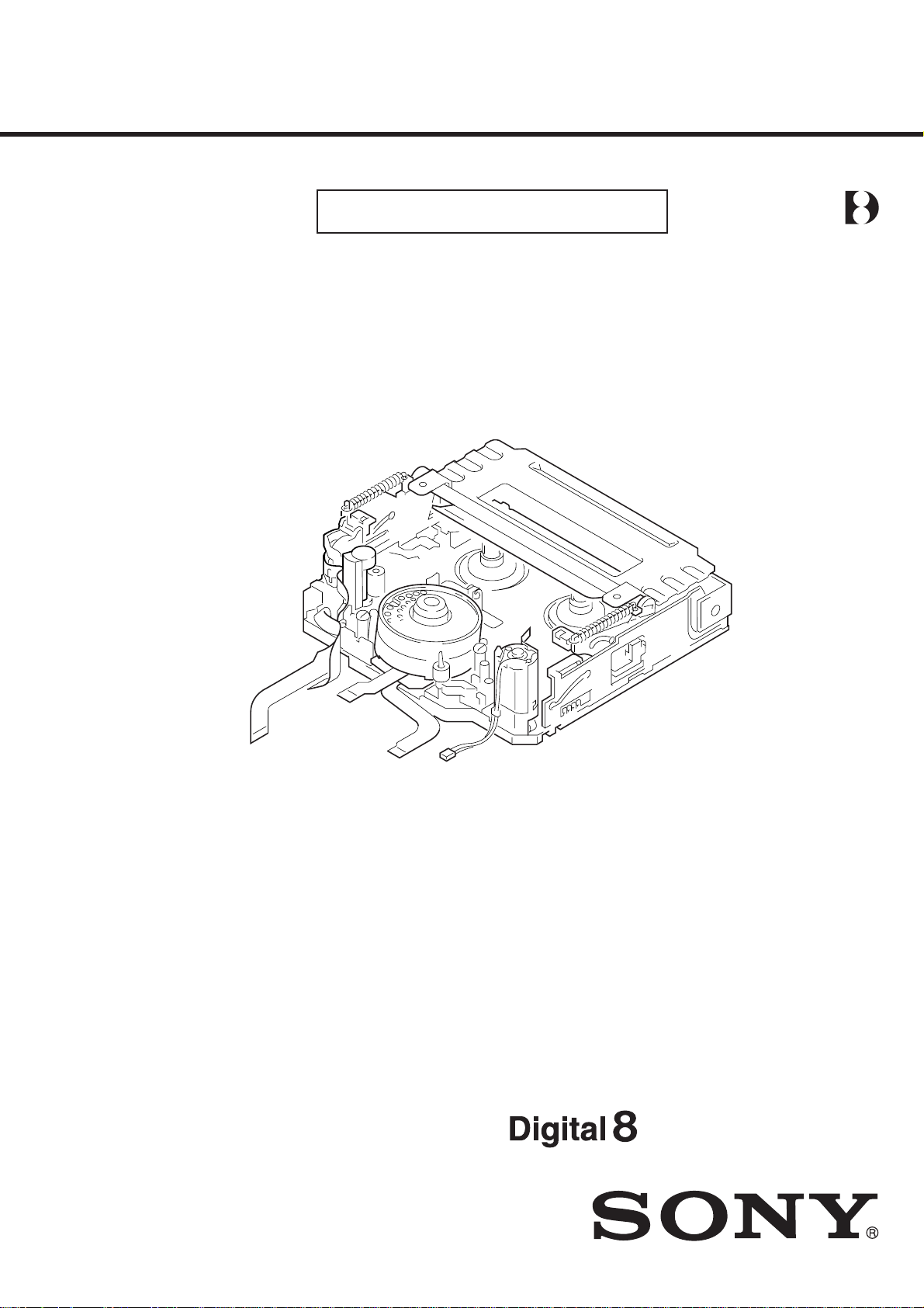
M2000 MECHANISM
Please use this manual with the service manual of the respective models.
MECHANISM DECK
Page 2

TABLE OF CONTENTS
1. Preparations for Check, Adjustment and
Replacement of Mechanism Block
1-1. Service Jigs and Tools ························································ 3
1-2. Mode Selector II Operating Procedure·······························5
2. Periodic Inspection and Maintenance
2-1. Rotary Drum Cleaning ······················································· 9
2-2. Tape Path System Cleaning ················································ 9
2-3. Periodic Inspection List····················································10
2-4. Appling Oil and Grease ···················································· 10
3. Before Replacement, Check or Adjustment
3-1. Phase Adjustment ····························································· 11
3-2. Cassette compartment assembly·······································12
4. Check, Adjustment and Replacement
4-1. Drum Assembly ································································ 14
4-2. HCL Arm Assembly, Loading Motor Assembly ·············· 15
4-3. Drum Base Assembly, Drum Earth ·································· 16
4-4. Guide Rail T2, Capstan Motor ········································· 17
4-5. Blind Plate, Lock Guide ··················································· 18
4-6. Reel Table (T) Assembly, T Soft Assembly ····················· 19
4-7. S Ratchet RE Plate, Cassette Guide S ······························ 20
4-8. R Drive Gear Assembly, LS Cam Plate···························· 21
4-9. LS Cam Plate Position Adjustment ·································· 22
4-10. LS Chassis Block Assembly············································· 23
4-11. TG7 Arm Block Assembly, Pinch Arm Assembly ··········· 24
4-12. Guide Base (T) Block Assembly,
Guide Base (S) Block Assembly ······································ 25
4-13. TG1 Arm, Reel Tab le (S) Assembly, Push Switch (3Key) · 26
4-14. Hall Element (H001, H002 (T/S Reel)),
Photo Transistor (Q001, Q002 (Tape Top/Tape End)),
LED (D001 (Tape LED))·················································· 27
4-15. LS Guide Roller, Guide Lock Plate (T),
Pinch Pusher Assembly, Eject Arm···································· 28
4-16. Rotary Switch, Cam Relay Gear,
Change Gear Assembly, Timing Belt ······························· 29
4-17. Guide Gear Assembly, Guide Gear T Assembly,
Cam Relay Gear 1, Guide Lock Plate (S) ························ 30
4-18. LD Gear 4, Cam Gear 1, HC Drive Arm ·························· 31
4-19. M Slide Plate Assembly, LS Arm Assembly,
Cam Gear 2, GL Arm Assembly ······································ 32
5. Adjustment
5-1. Check and Adjustment of TG1 Back-tension Position····· 33
5-2. Check and Adjustment of FWD/RVS Back-tension·········34
5-3. Capstan Motor Azimuth Position Adjustment·················· 35
5-4. Tape Path Adjustment ······················································· 36
6. Exploded Views
6-1. Cassette Compartment Assy, Drum Assy ························· 40
6-2. LS Chassis Block Assembly············································· 41
6-3. Mechanical Chassis Block Assembly-1 ··························· 42
6-4. Mechanical Chassis Block Assembly-2 ··························· 43
7. Printed Wiring Boards and
Schematic Diagrams .............................................. 44
— 2 —
Page 3

1. Preparations for Check, Adjustment and Replacement of Mechanism Block
Before Replacement, Check or Adjustment
• Refer to the “DISASSEMBLY” section of the SER VICE MANU AL of the respectiv e models for details of removing cabinets and printed
wiring boards.
• When checking a mechanism ir making any adjustment to the mechanism or r eplacing mechanical parts, be sure to use the Mode Selector
II and select the appropriate status of the mechanical deck such that the mechanical status is suitable for the desired work. Refer to section
“1-2. Mode Selector II Operating Procedure” for details on how to enter the mode shown in a rectangle [ ] mode in the sequent sections
of this manual.
* Assemble and adjust the parts in the [USE] mode if any mode is not specified in this manual.
1-1. Service Jigs and Tools
Ref. No.
J-1
Cleaning fluid
J-2
Wiping cloth
Super-fine applicator
J-3
(made by Nippon Applicator (P752D))
J-4
Head eraser
J-5
Mirror (small oval type)
J-6
Alignment tape
J-7
FWD/RVS take-up torque cassette
J-8
Tape path screwdriver
J-9
Adjustment remote commander (
J-10
MD process table
J-11
Floil grease
J-12
Torque screwdriver
J-13
Mode Selector II
J-14
Mode Selector II conversion board
J-15
Mode Selector II ROM, Ver 1.6
J-16
Thickness gauge
Other required equipment:
• Oscilloscope
• Analog tester (20 kΩ)
Name
NTSC : WR5-1NP
PAL : WR5-1CP
RM-95 upgrated
Part code
Y-2031-001-0
7-741-900-53
commercially available
J-6080-840-A
8-967-995-02
8-967-995-07
J-6080-824-A
J-6082-026-A
)
J-6082-053-B
J-6082-166-A
7-662-001-39
J-9049-330-A
J-6082-282-B
J-6082-516-A
J-6082-314-E
9-911-053-00
Note: If the micro processor IC in the adjustment remote commander is
Jig inscription
Tape path
GD-2038
GD-2086
not the new micro processor (UPD7503G-C56-12), the pages cannot
be switched. In this case, replace with the new micro processor (8759-148-35).
Tape path
For tracking adjustment
For tape guide adjustment
Tape path (for setting the path mode)(Note)
For capstan azimuth adjustment,
LS cam plate position adjustment
Used for
— 3 —
Page 4

J-1 J-2 J-3 J-4 J-5
J-6 J-7 J-8 J-9 J-10
J-11 J-12 J-13 J-14 J-15
J-16
Fig. 1-1.
— 4 —
Page 5
1-2. Mode Selector II Operating Procedure
1-2-1. Introduction
The Mode Selector II is a mechanism drive tool that assists
maintenance work of the various mechanism decks. It has the
following functions.
1. Manual Test
In this mode, the motor of the mechanism deck is powered only
during the period while the switch is turned on manually. Using the
Manual Test, the operator can freely control the motor of the
mechanism deck.
2. Step Test
In this mode, the motor of the mechanism deck is kept turned on
until the mechanical status is changed from the present mechanical
status that is obtained from the sensor information. The Step T est is
used to confirm a series of movements of the mechanism deck.
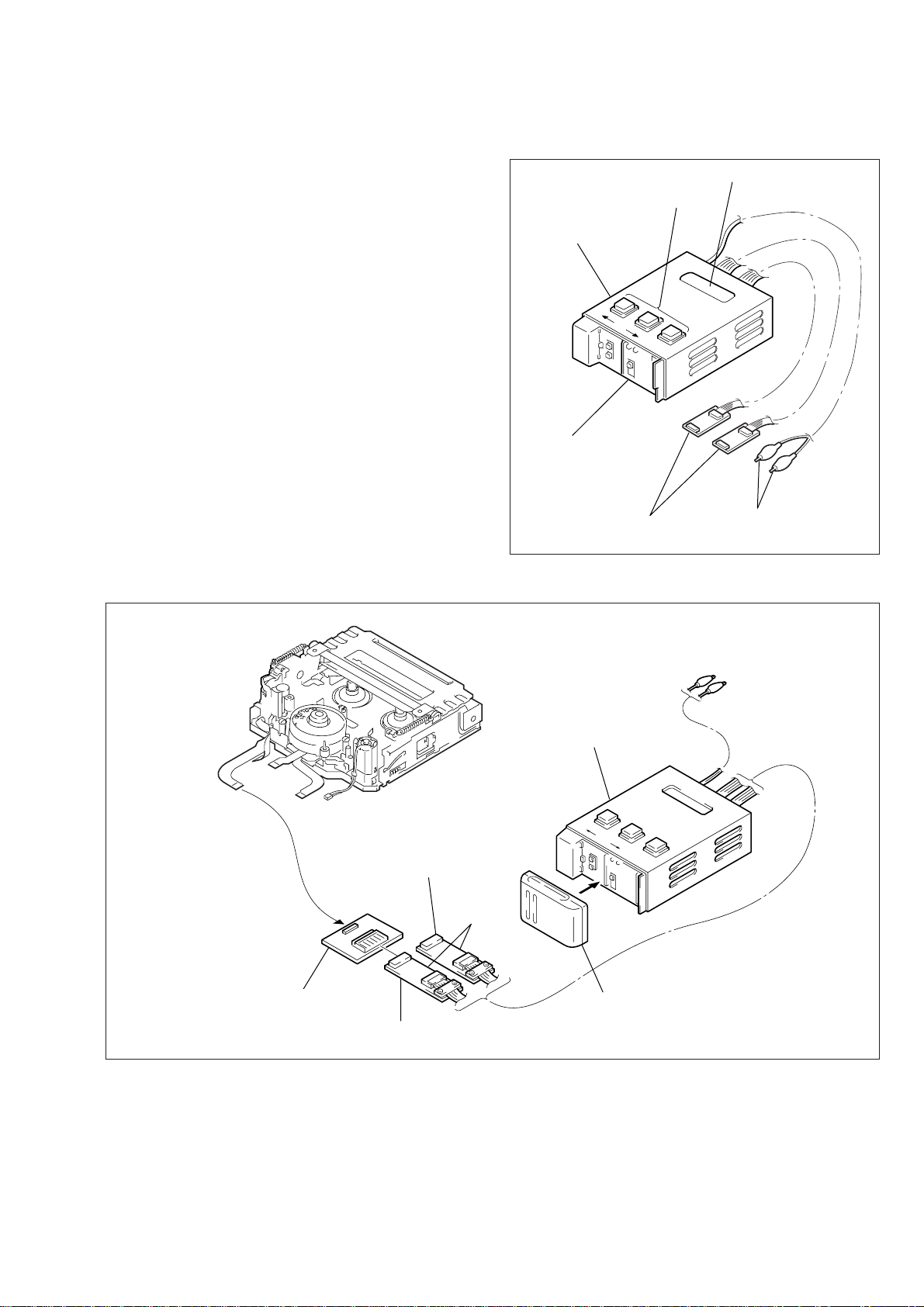
LCD display screen
Selector button
Mode Selector II
(Ref. No. J-13)
RVS
FF
SEL
3. Auto Test
The Mode Selector II stores the status transition table in its memory
as data indicating the respective modes of the mechanism deck.
The status transition table can be used to confirm whether a
mechanism deck is operating normally or has abnormality from a
series of movements of a mechanism deck. If an abnormal status
transition is detected during operation, the “NG” indication appears
and the mechanism stops moving.
Mode Selector II (J-6082-282-B) connection diagram
M2000 mechanism
Connector (black) 6-pin
(not used in M2000 mechanism)
External battery is
connected here as
a power supply
Relay board
(already connected)
Mode selector ll
Alligator clip
Fig. 1-2.
Alligator clip
(not used in M2000 mechanism)
Mode selector ll
conversion board (M)
(Ref. No. J-14)
Relay board
Battery such as NP-55, NP-77
(power supply)
Connector (white) 6-pin
Fig. 1-3.
— 5 —
Page 6
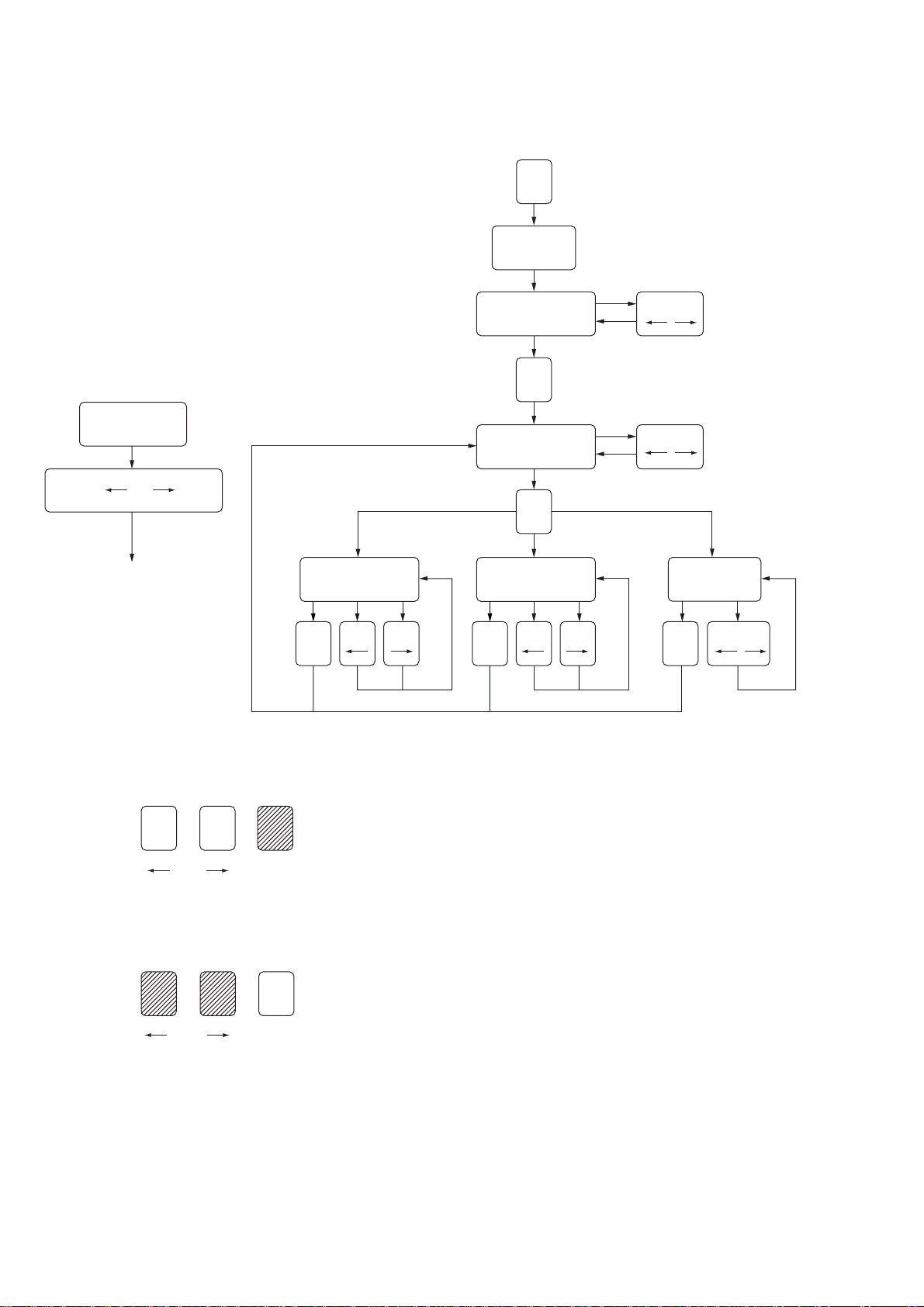
1-2-2. Operation
1. Operation Flow Chart
Note: The ROM in the Mode Selector II supports the M2000 mechanism.
From any status
Press RVS and FF for
2 sec. simultaneously
Main power is
turned off
MANUAL TEST
SEL
POWER ON
MECHA SELECT
SEL
MODE SELECT
SEL
STEP TEST
RVS, FF
RVS, FF
AUT O TEST
2. Mode Selector II Power On
Turn on the main power of the Mode Selector II as follows.
Press the SEL button.
RVS FF SEL
3. Mode Selector II Power Off
Turn off the main power of the Mode Selector II as follows.
Press the RVS and FF buttons at the same time for 2 seconds or
longer while the power is on.
RVS FF SEL
RVS, FFSELRVS FFSELRVS FFSEL
— 6 —
Page 7
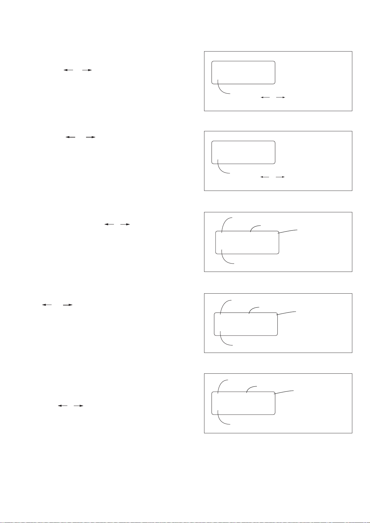
4. Mecha Select
)
)
)
When the main power is turned on, the MECHA SELECT display
appears on the LCD screen. Select the desired mechanism name
using the R VS and FF buttons. Selection is complete when the SEL
button is pressed. (Fig. A shows the B mechanism.)
5. Test Type Select
Using the RVS and FF buttons, select a desired test type from the
three types of “MANUAL”, “STEP” and “AUTO”. Selection is
complete when the SEL button is pressed.
6. Manual Test
In this test, the motor of the mechanism deck is turned on only
during the period while the R VS or FF button is pressed manually.
MECHA SELECT
B
Pressing the RVS or FF button
changes the mechanism name.
Fig. a
TEST TYPE SELECT
MANUAL
Pressing the RVS or FF button cycles
among MANUAL, STEP, AUTO in this order.
Fig. b
Mechanism name
Present mode
Motor ON/OFF
B MANUAL OFF
STATUS
7. Step Test
In this test, the direction of motor movement is determined by the
RVS and FF buttons. The motor of the mechanism deck is kept
turned on until the mechanical status is changed from the present
mechanical status that is obtained from the sensor information.
8. Auto Test
In this test, the mechanism deck is tested as to whether it performs
a series of movements correctly in accordance with the operation
sequence that is memorized earlier for each type of deck, by checking
the output signals from sensors with the stored memory. Turning
on the RVS or FF button performs the same operation.
Present status of sensor appears. (example: EJ
Fig. c
Mechanism name
Present mode
Motor ON/OFF
B STEP OFF
STATUS
Present status of sensor appears. (example: EJ
Fig. d
Mechanism name
Present mode
Motor ON/OFF
B AUTO OFF
STATUS
Present status of sensor appears. (example: EJ
Fig. e
— 7 —
Page 8

1-2-3. Mechanism Status (Position) Transition Table Using Mode Selector II
After selecting a mechanism deck, select either the MANUAL or
STEP test (not AUTO) using the Mode Selector II. The desired
mechanism status (position) can be specified by pressing the RVS
or FF button. (The selected status appears on STATUS.)
EJyUSEyLOADySTOPyTURNyRPyREW
1-2-4. Battery Alarm Indication
When the level of the battery used to supply power to this system
decreases, this display appears asynchronously . When this happens,
all operations are disabled and the battery must be replaced.
MD name
Code
ABC
100
110
010
011
001
000
101
0 is common and short.
[
1 is common and open.
M2000 Mechanism
1
EJ
2
USE
3
LOAD
4
STOP
5
TURN
6
RP
7
REW
BATT DOWN
CHANGE PLEASE
Fig. f
]
— 8 —
Page 9
2. Periodic Inspection and Maintenance
r
• Be sure to perform the following maintenance and inspection so
that the machine delivers its full performance and functions, and
to protect the machine and tape. Also, perform the following
maintenance items after completing the repair work, regardless
of the number of hours the machine has been operated by the
user.
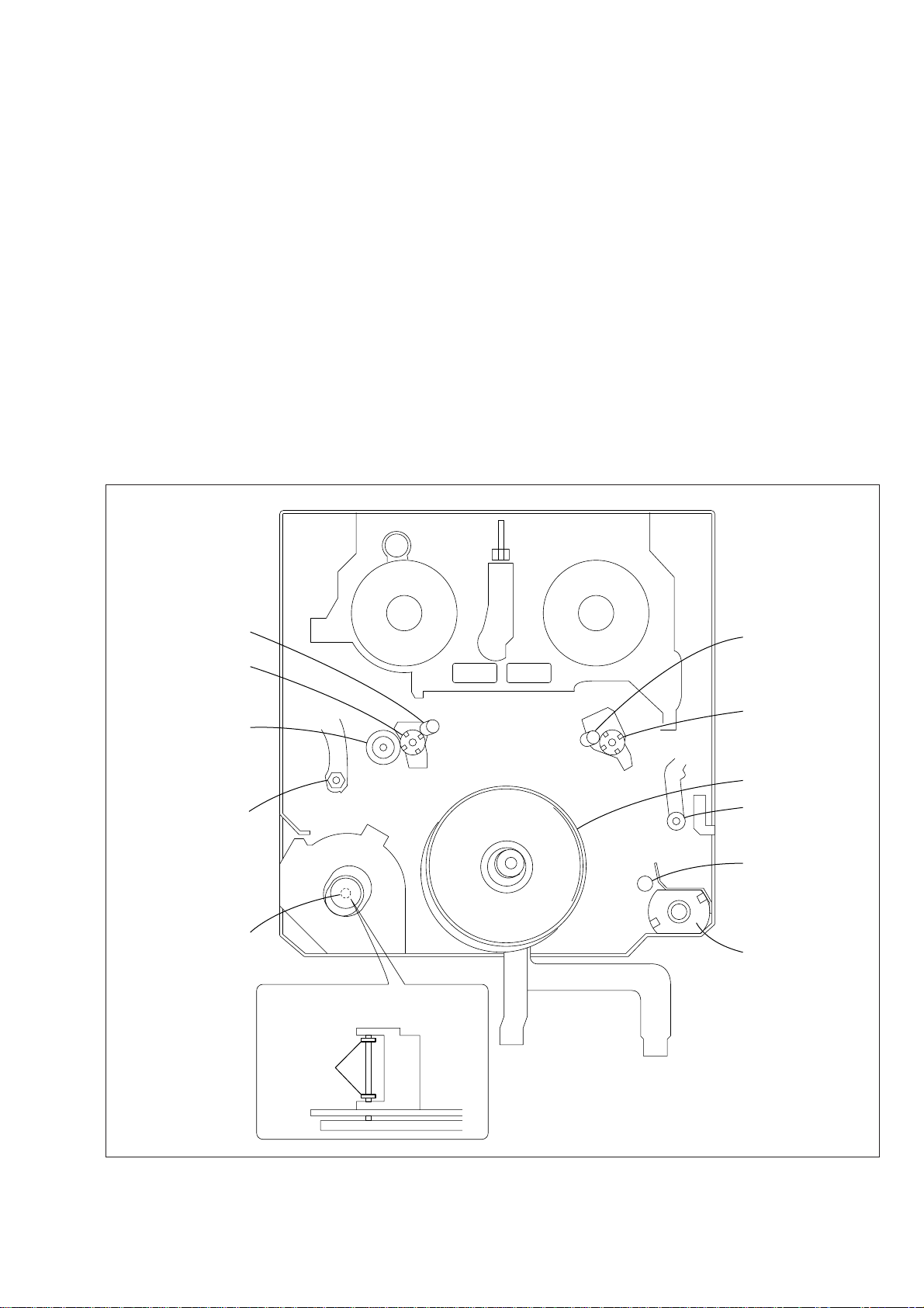
2-1. Rotary Drum Cleaning
1) Press a wiping cloth (Ref. No. J-2) moistened with cleaning
fluid (Ref. No. J-1) lightly against the rotary drum. Rotate the
upper drum with a super-fine applicator slo wly in the counterclockwise direction to clean the rotary drum.
Caution: Never rotate the rotary drum by turning on the main power of
the motor or rotate it in the clockwise direction. Never move the
cloth vertically against the head tip, as this will surely damage
the video head; the video head must not be cleaned by any other
different methods.
TG5
T-reel
TG6
2-2. Tape Path System Cleaning
(Refer to Fig. 2-1.)
1) Set the EJECT state. Clean the tape running path (TG1, 2, 3,
4, 5, 6 and 7, pinch roller and capstan shaft) and lower drum
with a super-fine applicator (Ref. No. J-3) moistened with
cleaning fluid.
Note 1: Be careful not to allow oil or grease of the various link mechanisms
Note 2: Once the super-fine applicator has been moistened with alcohol,
Note 3: When cleaning the capstan shaft, be carefull not to move the oil
to get on the super-fine applicator (Ref. No. J-3).
do not use it to clean other mechanical parts such as the tape guide.
However, the pinch roller is cleaned with alcohol.
seal. If the oil seal is moved, oil will leak.
S-reel
TG4
Pinch roller
TG7
Capstan shaft
TG3
Drum
TG1
TG2
Loading moto
Capstan shaft cleaning
Oil seal
Fig. 2-1
— 9 —
Page 10
2-3. Periodic Inspection List
r
Maintenance and inspection item
Tape running surface cleaning
Rotary drum cleaning and
degaussing
Timing belt
Capstan shaft
Drive
mechanism
Loading motor
Abnormal sound
Back-tension measurement
Brake system
check
Performance
FWD/RVS torque measurement
Note: When the machine is overhauled, replace the parts referring to the
above list.
500
a
a
—
—
—
✩
—
—
—
1000
a
a
✩
✩
✩
✩
✩
✩
✩
1500
a
a
—
—
—
✩
—
—
—
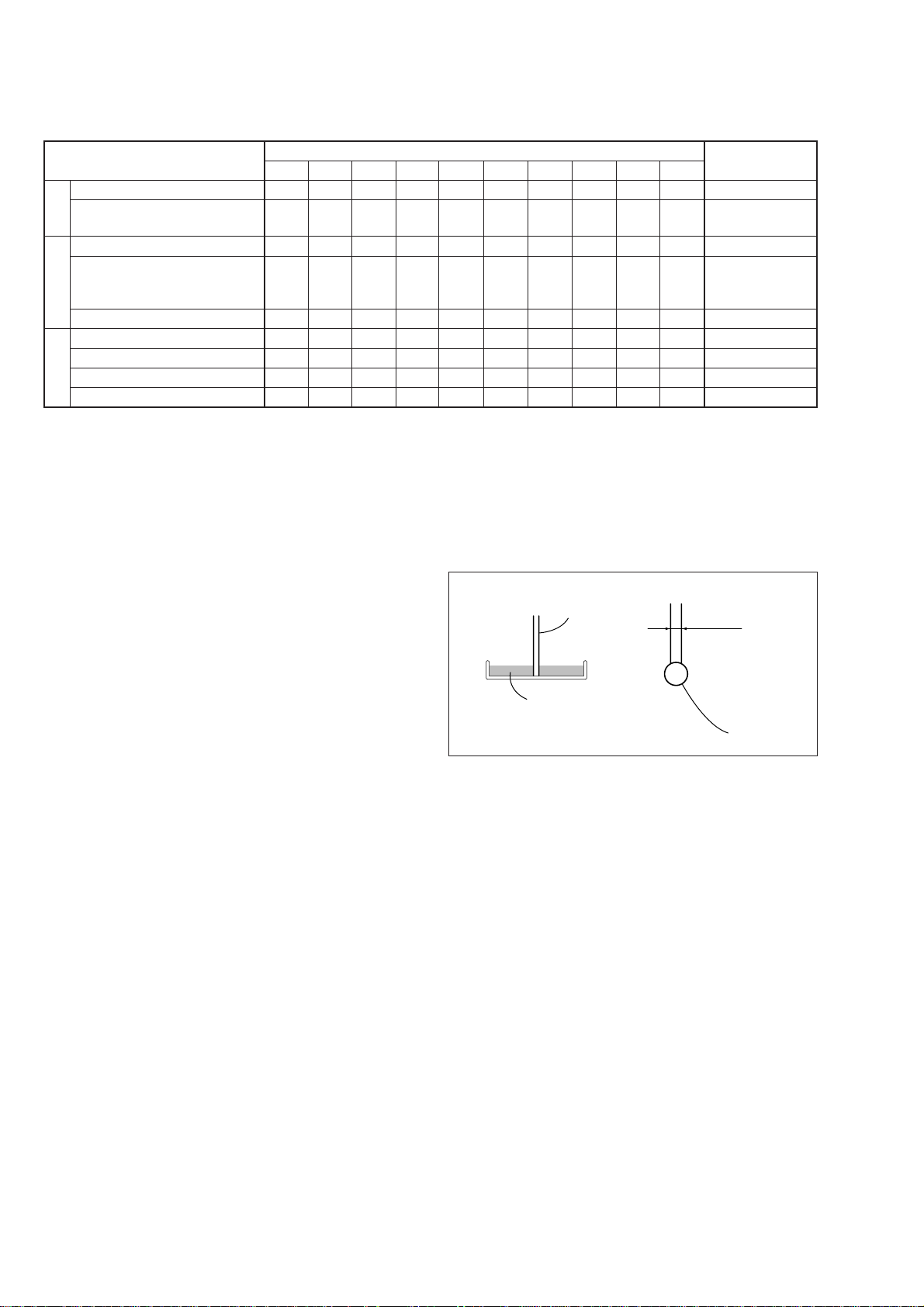
2-4. Appling Oil and Grease
When replacing or assembling the parts, use oil and grease while
referring to the following.
On Oil
• Be sure to use the specified grease only. (If oil of different viscosity
is used, it can cause various troubles.)
Oil: Part No. 7-661-018-18
(Mitsubishi diamond oil hydro fluid NT-68)
• The oil used for bearings must not contain any dust or other
materials, otherwise excessive abrasion and seizure of the bearing
could occur.
• A drop of oil means the amount of oil as shown in the illustration
in the right, which is the amount that is attracted to the top of a
rod of 2 mm diameter.
Operating hours (H)
2000
2500
3000
a
a
a
a
a
a
✩
—
✩
✩
—
✩
✩
—
✩
✩
✩
✩
✩
—
✩
✩
—
✩
✩
—
✩
3500
4000
a
a
a
a
—
✩
—
✩
—
✩
✩
✩
—
✩
—
✩
—
✩
Metal rod of
1 mm diameter
Fill the oil of
about 2 mm depth
4500
a
a
—
—
—
✩
—
—
—
5000
a
a
Remarks
Be careful not to attach oil
Be careful not to attach oil
✩
Never attach oil to the
✩
tape running path during
periodic inspection.
✩
✩
✩
✩
✩
a: Cleaning, ✩: Check
1 mm diamete
Oil
On Grease
• Be sure to use the specified grease only. (If oil of different viscosity
is used, it can cause various troubles.)
Floil grease: Part No. 7-662-001-39
• Be sure to use grease into which dust is not mixed.
• The amount of grease is 1 to 1.5 mm diameter in length.
Fig. 2-2
— 10 —
Page 11
3. Before Replacement, Check or Adjustment
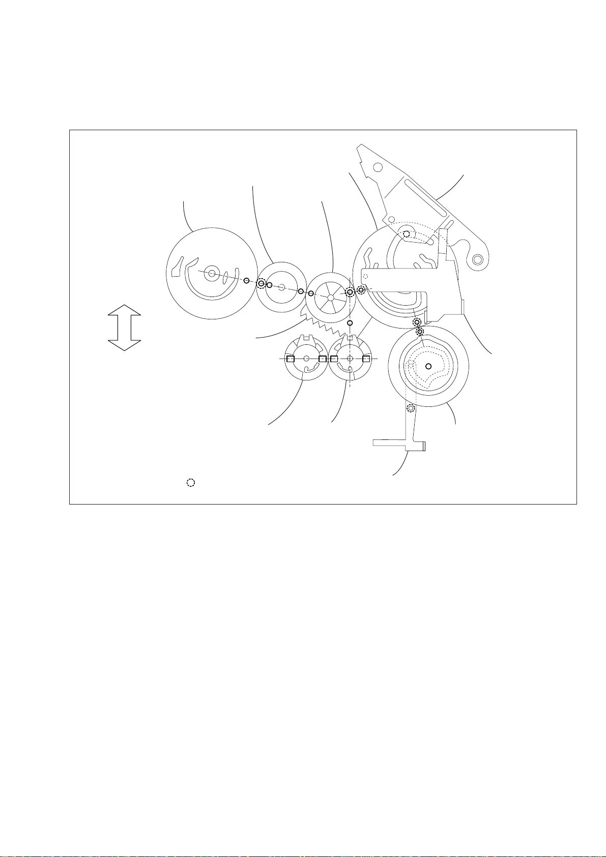
3-1. Phase Adjustment
The phase adjustment of this mechanism block has been adjusted
by using the in-phase markings shown in the following figure.
When replacing or assembling the parts, check the phase.
Cam gear (2) LS arm assembly
Cam relay gear (2)
Rotary switch
Front side
Cam relay gear (1)
Drum side
GL arm assembly
Guide gear
(S) assembly
Hole of mechanism chassis
Guide gear
(T) assembly
Fig. 3-1.
HC drive arm
Cam gear (1)
M slide plate
assembly
— 11 —
Page 12

3-2. Cassette compartment assembly
1. Removal procedure
1) Set the [EJ] mode to move up the cassette compartment
assembly 0.
2) Remove the capstan flexible board and flexible wiring board
(FP-300) 1 from the holders X, Y and Z in the directions
of the arrows A, B and C.
3) Push the damper assembly 3 in the directions of the arrows
D and E and remove it from the notch of the LS chassis block
assembly .
4) Remove the two screws (camera pan2 main M1.4 × 1.6) 4.
5) With the cassette compartment assembly 0 half opened , move
the face plate in the direction of the arrow F and remove it
from the grooves 6 and 7 on the LS chassis block assembly .
6) Remove the cassette holder (S) 8 and cassette holder (T) 9
of the cassette compartment assembly 0 from the groove on
the LS chassis block assembly.
2. Attachment procedure
1) Set the [USE] mode.
2) Insert the cassette holder (S) 8 of the cassette compartment
assembly 0 and cassette holder (T) 9 into the grooves on
both sides of the LS chassis block assembly.
3) While moving down the cassette compartment assembly 0,
lift up the face plate in the direction of the arrow F and keep
this status. Then, insert the face plate in the grooves 6 and 7
on the LS chassis block assembly.
4) Tighten the two screws (camera pan2 main M1.4×1.6) 4.
Tightening torque: 0.078 ± 0.01 N•m (0.8 ± 0.1 kgf•cm)
5) Move the damper arm of the damper assembly 3 to the 4
o’clock position and insert the damper assembly into the hole
on the LS chassis block assembly and the dowel of the cassette
holder (T) 9.
6) Align the damper assembly 3 with the notch of the LS chassis
block assembly and rotate the damper assembly 3 in the
opposite direction to the arrow E to fix it.
— 12 —
Page 13
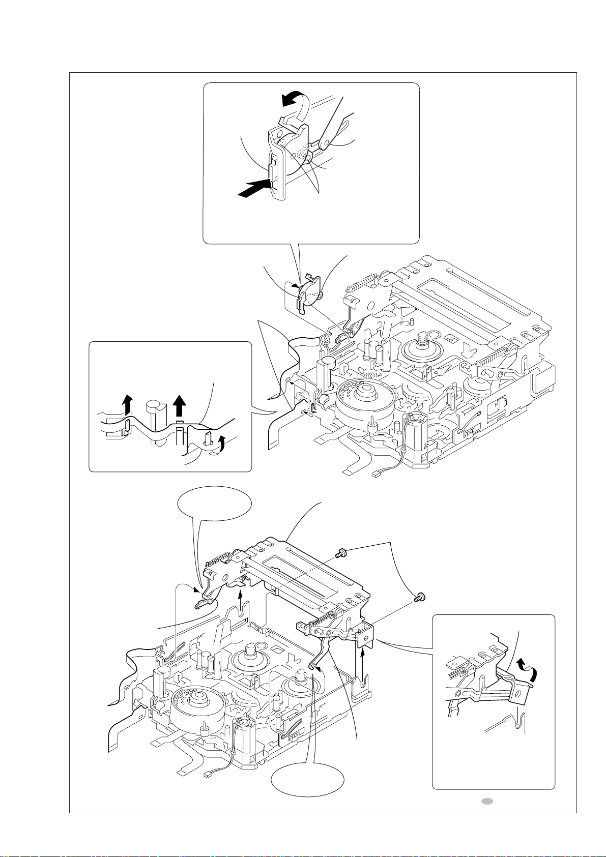
Damper
assembly
E
Cassette holder (T)
1
FP-300 flexible board,
Capstan flexible board
Remove the flexible board in the
direction of the arrow
C
Z
Capstan flexible board
A B C
FP-300 flexible board
B
X
Y
D
Push
2
Remove the damper assembly in the direction
of the arrow
3
Damper assembly
.
A
E
.
Move the damper arm
to the 4 o'clock position.
Insert into these holes
and attach.
Damper arm
*
Be careful not to
deform here.
Cassette holder (T)
While pressing
toward the inside
9
7
0
Cassette compartment
assembly
8
Cassette holder (S)
While pressing
toward the inside
4
(camera pan 2 main M1.4
6
*
Be careful not to
deform here.
T wo screws
×
1.6)
Face plate
F
5
Remove the cassette
compartment assembly
in the direction of the
arrow
F
.
Fig. 3-2.
— 13 —
When attaching it, coat the hatched portion with grease.
Page 14
4. Check, Adjustment and Replacement
Note: For removal procedure of the cabinets, printed wiring boards and other parts, refer to “DISASSEMBLY” of the Service Manual of the respective
models.
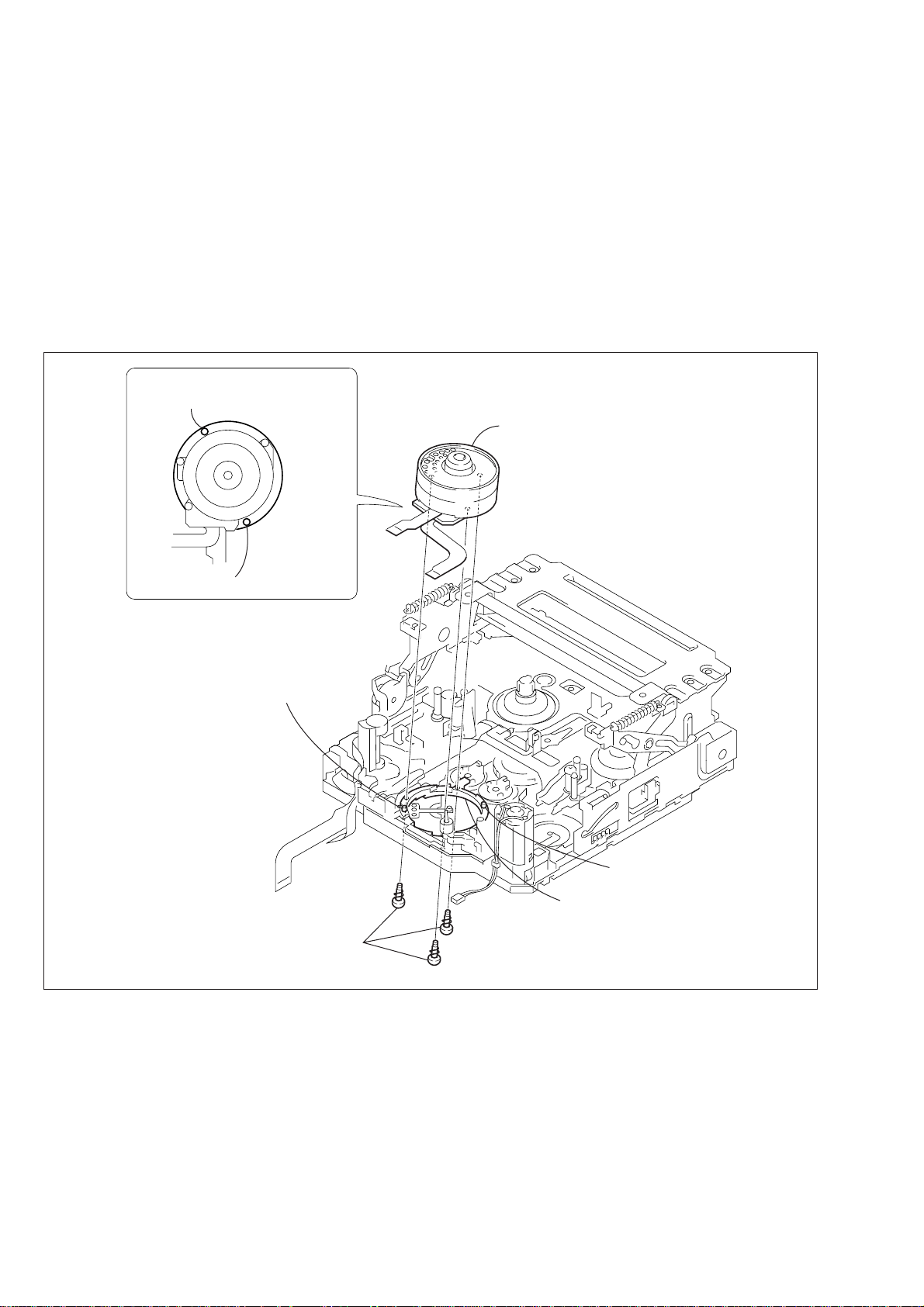
4-1. Drum Assembly
1. Removal procedure
1) Remove the three screws (drum fitting M1.4 × 2.5) 1 fixing
the drum and remove the drum.
Drum (rear view)
Hole (reference hole B)
Hole (reference hole A)
2. Attachment procedure
1) Align the two reference holes A and B on the rear of the drum
with the reference pins A and B of the drum base assembly.
2) Attach the drum with the three screws (drum fitting M1.4 ×
2.5) 1 in the order of A, B and C.
Tightening torque: 0.078 ± 0.01 N•m (0.8 ± 0.1 kgf•cm)
3) Clean the drum while referring to 2-1.
4) Adjust the tape path. (Refer to “4. Tape Path Adjustment”.)
Note: Do not touch the outside circumference.
Drum
Reference pin A
1
Three screws
(drum fitting M1.4
×
2.5)
B
Reference pin B
Drum base assembly
C
A
Fig. 4-1.
— 14 —
Page 15

4-2. HCL Arm Assembly, Loading Motor Assembly
1. Removal procedure
1) Hook the HC arm spring in the direction of the arrow B.
2) Remove the HCL arm assembly 2 from the loading motor
assembly 4.
3) Remove the screw (M1.4 × 2.5) 3.
4) Remove the three claws of the loading motor assembly 4 from
the mechanism chassis assembly in the direction of the arrow
A.
Hook the HC arm spring on the notch
of the loading motor assembly.
B
2. Attachment procedure
1) Coat the worm shaft and gear of the loading motor assembly
4 with grease.
2) Insert the three claws of the loading motor assembly 4 into
the groove on the mechanism chassis assembly.
3) Attach the screw (M1.4 × 2.5) 3.
Tightening torque: 0.078 ± 0.01 N•m (0.8 ± 0.1 kgf•cm)
4) Check the position of the HCL arm assembly 2 and the HC
drive arm. Then attach the HCL arm assembly 2 to the loading
motor assembly 4.
5) Hook the HC arm spring 1 on the notch of the loading motor
assembly 4.
6) Clean the drum assembly. (Refer to section 2-1.)
2
HCL arm
assembly
Drive pin
3
Screw
×
(M1.4
A polarity exists.
The marked side has
a red line.
4
assembly
2.5)
Loading motor
Remove the loading motor
assembly in the direction
of the arrow
A
.
A
1
Pull and hook the HC arm spring in
the direction of the arrow
When attaching it, coat the hatched
portion with grease.
Drive pin
HC drive arm
B
.
Loading motor
assembly
(rear view)
Three
claws
Mechanical chassis assembly
Cover
sheet
Loading motor
assembly
Fig. 4-2.
— 15 —
Page 16

4-3. Drum Base Assembly, Drum Earth
1. Removal procedure
1) Remove the capstan flexible board and flexible wiring board
(FP-300) from the holders X, Y and Z in the direction of the
arrow .
2) Remove the drum assembly. (Refer to section 4-1.)
3) Remove the screw (M1.4 × 2.5) 2.
4) Remove the claw D of the guide rail T2 3 from the hole E
of the drum base assembly in the direction of the arrow F.
5) Remove the three screws (M1.4 × 2.5) 4.
6) Remove the drum base assembly 5 in the direction of the arro w .
7) Remove the screw (screw assy PW M1.7 × 2.6) 6.
8) Remove the drum earth 7 and earth spacer 8.
Guide rail
(T2)
Remove the guide rail
(T2) in the direction
of the arrow
F
.
F
Claw
Drum base assembly
D
2. Attachment procedure
1) Attach the ground spacer 8 and drum ground 7 with the scre w
(screw assy PW M1.7 × 2.6) 6.
Tightening torque: 0.078 ± 0.01 N•m (0.8 ± 0.1 kgf•cm)
2) Align the drum base assembly 5 with the reference pin and
tighten the three screws (M1.4 × 2.5) 4 in the order of G, H
and I.
3) Insert the claw D of the guide rail T23 into the hole E of the
drum base assembly 5 and tighten the screw (M1.4 × 2.5) 2.
Tightening torque: 0.078 ± 0.01 N•m (0.8 kgf•cm)
4) Remove the drum assembly. (Refer to 4-1.)
5) Attach the flexible wiring board (FP-300) 1 and capstan
flexible board to the drum base assembly.
6) Clean the tape running path. (Refer to 2-2.)
hole
H
E
G
I
4
Three screws
(M1.4
5
Drum base
assembly
×
2.5)
3
Guide
rail (T2)
2
Screw
(M1.4
×
2.5)
Remove the flexible board in the
direction of the arrow
C
Z
Capstan flexible board
1
FP-300 flexible board,
Capstan flexible board
A B C
FP-300 flexible board
B
X
Y
A
Two dowels
.
6
Screw
(screw assy PW
M1.7
×
2.6)
7
Drum
ground
8
Ground
spacer
Claw
D
Fig. 4-3.
— 16 —
Page 17

4-4. Guide Rail T2, Capstan Motor
1. Removal procedure
1) Remove the capstan flexible board and flexible wiring board
(FP-300) 1 from the holders X, Y and Z in the directions
of the arrows A, B and C.
2) Remove the screw (M1.4 × 2.5) 2.
3) Remove the claw of the guide rail T2 3 from the hole on the
drum base assembly in the direction of the arrow D.
4) Remove the six solderings 4.
5) Remove the FP-228 flexible wiring board (2P) (DEW sensor)
5.
6) Remove the two screws (camera pan2 main M1.4 × 1.6) 6
and the screw (SANG camera pan2 main M1.4 × 4.5) 7.
7) Remove the capstan motor 8.
8) Remove the capstan spring 9 (be careful not to dr op the capstan
spring) and timing belt 0.
Attachment position of
FP-228 flexible board
Approx.0.5mm
6
T wo screws
(camera pan 2 main
M1.4 × 1.6)
7
Screw
(SANG camera pan
2 main M1.4 × 4.5)
5
FP-228 flexible
board (2P)
(DEW sensor)
8
Capstan motor
3
Guide rail (T2)
2. Attachment procedure
1) Hook the timing belt 0 on the gear of the capstan motor 8,
attach the capstan motor while aligning it with the reference
boss of the mechanism chassis assembly.
2) Attach the screw (SANG camera pan2 M1.4 × 4.5) 7 and
capstan spring 9. (temporally attachment)
3) Attach the two screws (camera pan2 M1.4 × 1.6) 6.
Tightening torque: 0.078 ± 0.01 N•m (0.8 ± 0.1 kgf•cm)
4) Attach the six solderings 4 to the FP-228 flexible wiring board
5 (2P) (DEW sensor) and the FP-299 flexible wiring board
(4P).
5) Insert the guide rail T2 3 into the hole on the drum base
assembly and tighten the screw (M1.4 × 2.5) 2.
Tightening torque: 0.078 ± 0.01 N•m (0.8 ± 0.1 kgf•cm)
6) Attach the capstan flexible board and the flexible wiring board
(FP-300) 1 to the holders X, Y and Z.
7) Adjust the height of the capstan motor using the thickness gauge
(Ref. No. J-16). (Refer to 5-3.)
Note: Be careful not to touch the center of the capstan motor 0 shaft and
the FP-228 flexible wiring board (DEW sensor) with soldering iron
or other tool.
2
Screw
(M1.4 × 2.5)
Remove the Guide rail (T2)
in the direction of the
D
.
Guide rail
(T2)
D
Drum base
assembly
4
Remove the
six solderings
FP-299 flexible
board (4P)
arrow
1
FP-300 flexible board,
Capstan flexible board
Remove the flexible board in the
direction of the arrow A B C.
FP-300 flexible board
C
Z
Capstan flexible board
B
X
Y
9
Capstan spring
A
Fig. 4-4.
— 17 —
0
Timing belt
Note: Any foreign materials must not be attached
to the capstan motor.
Page 18

4-5. Blind Plate, Lock Guide
1. Removal procedure
1) Remove the diode D001 (tape LED) 1 from the notch of the
plate 4.
2) Remove the flexible wiring board 2 (FP-301) from T-shaped
portion of the blind plate 4 in the direction of the arrow A.
3) Remove the screw (camera pan2 main M1.4 × 1.6) 3.
4) Release the hook on the notches G, D, E and F of the blind
plate 4 in the direction of the arrow B.
5) Remove the reel release lever 5 in the direction of the arrow
C.
3
Screw
(camera pan 2 main M1.4 × 1.6)
4
Remove the blind plate in the
direction of the arrow B.
Notch
G
A
2. Attachment procedure
1) Attach the reel release lever 5 to the blind plate 4.
2) Hang the notches G, D, E and F of the blind plate 4 on
the hook.
3) Attach the screw (camera pan2 main M1.4 × 1.6) 3.
Tightening torque: 0.078 ± 0.01 N•m (0.8 ± 0.1 kgf•cm)
4) Attach the flexible wiring board (FP-301) 2 to the T-shaped
portion of the blind plate 4.
5) Attach the diode (tape LED) 1 to the notch of the blind plate
4.
C
5
Remove the reel release
lever in the direction of
the arrow C.
Claw
Notch
D
Notch
B
E
2
Remove the FP-301 flexible
board in the direction of
the arrow A.
Fig. 4-5.
Notch
F
1
D001
Diode (tape LED)
— 18 —
Page 19

4-6. Reel Table (T) Assembly, T Soft Assembly
1. Removal procedure
1) Remove the blind plate. (Refer to 4-5.)
2) Open the claw of the reel table T assembly 1 in the directions
of the arrows B and C and remove the reel table T assembly.
3) Remove the T soft assembly 2 in the direction of the arrow
A.
4) Remove the T ratchet spring 3.
5) Remove the T ratchet arm 4 in the direction of the arro w D.
Open the claw of the reel table T
in the directions of the arrows
B
and C.
B
C
2. Attachment procedure
1) Insert the T ratchet arm 4 into the groove on the LS chassis
block assembly to attach it.
2) Attach the T ratchet spring 3 to the notch of the T ratchet arm
4 and LS chassis block assembly.
3) Insert the T soft assembly into the groove on the LS chassis
block assembly.
4) Check the location of the reel table T assembly and attach the
LS chassis block assembly to the shaft.
5) Attach the blind plate. (Refer to 4-5.)
Check the location of the reel
1
Reel table (T)
assembly
A
table (T) assembly.
The reel table (T)
assembly is at a
slant.
4
Remove the T ratchet arm in
the direction of the arrow D.
D
Fig. 4-6.
2
Remove the T soft assembly in the
direction of the arrow A.
3
T ratchet
spring
When attaching it, coat the hatched
portion with grease.
— 19 —
Page 20

4-7. S Ratchet RE Plate, Cassette Guide S
1. Removal procedure
1) Remove the blind plate. (Refer to 4-5.)
2) Remove the RE return plate spring 1.
3) Remove the S ratchet spring 2.
4) Remove the S ratchet arm 3 in the direction of the arrow A.
Note: Do not reuse the S ratchet arm.
5) Remove the S ratchet RE plate.
6) Remove the screw (camera tapping M1.4 × 2)5.
7) Remove the cassette guide S 6 in the direction of the arrow
B.
Remove the S ratchet arm in the
direction of the arrow
Do not reuse
the S ratchet arm.
Fixed here.
S ratchet spring
Remove the S ratchet (RE) plate in the
direction of the arrow
A
A
B
.
dowel
B
.
3
S ratchet arm
2. Attachment procedure
1) Attach the cassette guide S 6 to the notch of the LS chassis
block assembly with the screw (camera tapping M1.4 × 2).
2) Attach the S ratchet RE plate 4 to the shaft of the LS chassis
block assembly.
3) Attach the S ratchet arm 3 to the shaft of the LS chassis block
assembly. At this time, the dowel of the S ratchet RE plate 4
must be inserted into the U-shaped notch of the S ratchet arm
3.
4) Hook the S ratchet spring 2 on the notch of the S ratchet arm
and attach it to the notch of the LS chassis block assembly.
5) Attach the RE return plate spring 1 to the notch of the LS
chassis block assembly.
6) Attach the blind plate. (Refer to 4-5.)
2
S ratchet
spring
B
6
Remove the cassette
guide (S) in the direction
of the arrow
B
.
4
S ratchet
(RE) plate
Fig. 4-7.
1
RE return plate spring
5
Screw
(camera tapping M1.4
×
2)
— 20 —
Page 21

4-8. R Drive Gear Assembly, LS Cam Plate
1. Removal procedure
1) Remove the blind plate. (Refer to 4-5.)
2) Remove the lumiler cut washer (0.98 × 3 × 0.13) 1.
3) Remove the R drive gear assembly 2.
4) Remove the HLC cut (1.8 × 4 × 0.5) 3 and the two screws
(precision type3 +P1.7 × 1.8) 4.
5) Remove the LS cam plate 5.
5
LS cam plate
1
Lumiler (W)
cut (0.98 × 3 × 0.13)
Do not bend the claw.
2
R drive gear
assembly
2. Attachment procedure
1) Attach the R drive gear assembly 2 with the lumiler cut washer
(0.98 × 3 × 0.13) 1.
2) Align the LS cam plate 5 with the two dowels of the LS chassis
block assembly, temporarily fix the LS cam plate 5 with the
two screws (precision type3 +P1.7 × 1.8), then attach it with
the HLC cut (1.8 × 4 × 0.5) 3.
3) Adjust the position of the LS cam plate. (Refer to 4-9.)
4
T wo screws
(precision type3 +P1.7 × 1.8)
3
HLC cut (1.8 × 4 × 0.5)
When attaching it, coat
the hatched portion
with grease.
Fig. 4-8.
— 21 —
Two dowel
When attaching it, coat the hatched
portion with grease.
Page 22

4-9. LS Cam Plate Position Adjustment
s
1. Adjustment Pr ocedure
1) Perform loading of the LS chassis block assembly 1 until the
tip of the guide base (S) assembly reaches the drum base
assembly.
2) Loosen the two screws (precision type3 +P1.7 × 1.8) 2 of the
LS cam plate and slide the LS chassis block assembly to the
drum side so as to remove play.
3) Insert the thickness gauge 0.6 mm (Ref. No. J-16) between the
LS cam plate and the LS chassis block assembly . Push the LS
cam plate in the direction opposite to the drum to remove play .
4) Fix the two screws (precision type3 +P1.7 × 1.8) 2.
Tightening torque: 0.108 ± 0.01 N•m (1.1 kgf•cm)
Two screws
(precision type3 +P1.7
×
1.8)
Thickness
gauge
t =0.6mm
Two dowels
LS cam plate
Fig. 4-9.
Guide base (S)
block assembly
1
LS chassis
block assembly
Push the LS chassi
2
block assembly
to remove play.
— 22 —
Page 23

4-10.LS Chassis Block Assembly
1. Removal procedure
1) Move the LS chassis block assembly between [USE] and
[LOAD].
2) Remove the blind plate. (Refer to 4-5.)
3) Remove the R drive gear assembly. (Refer to 4-8.)
4) Remove the HCL cut (1.8 × 4 × 0.5) 1.
5) Remove the three screws (M1.4 × 2.5) 2.
6) Remove the LS chassis block assembly 3 in the direction of
the arrow A.
When attaching it, coat the hatched
portion with grease.
5
TG7 arm block
assembly
4
Slot of LS chassis
(at two locations)
2. Attachment procedure
1) Insert the LS guide roller and LS guide T2 pin of the mechanical
chassis block assembly into the slot of the LS chassis block
assembly 4.
2) Insert the pin of the LS arm assembly into the cam groove on
the LS cam plate, face the TG7 driv e pin 5 in the direction of
the arrow B, and insert it to the two slot of the mechanical
chassis. Then, tighten the three screws (M1.4 × 2.5) 2 in the
order of C, D and E.
Tightening torque: 0.078 ± 0.01 N•m (0.8 ± 0.1 kgf•cm)
3) Attach the HCL cut (1.8 × 4 × 0.5) 1 to the pin of the LS arm
assembly .
4) Attach the R drive gear assembly. (Refer to 4-8.)
5) Attach the blind plate. (Refer to 4-5.)
6) Clean the tape running path. (Refer to 2-2.)
Note: Each arm must move smoothly.
C
2
Three screws
D
E
(M1.4
LS cam plate
Cam groove
×
2.5)
1
HCL cut
(1.8
×
4 × 0.5)
3
Remove the LS chassis
block assembly in the
A
direction of the arrow
A
.
LS guide
T2 shaft
B
LS guide roller
Do not
bend here.
6 to 8mm
Fig. 4-10.
When attaching it, coat the
hatched portion
with grease.
Pin
LS arm assembly
Mechanical chassis block assembly
— 23 —
Page 24

4-11.TG7 Arm Block Assembly, Pinch Arm Assembly
1. Removal procedure
1) Remove the LS chassis block assembly. (Refer to 4-10.)
2) Remove the screw (camera pan2 M1.4 × 1.6) 1.
3) Remove the TG7 retainer 2 in the direction of the arrow.
4) Remove the TG7 arm block assembly 6 and TG7 arm spring
7.
5) Remove the pinch roller arm assembly 3.
6) Remove the P lim arm roller 4 and pinch arm load spring 5.
6
TG7 arm block
assembly
7
TG7 arm spring
PRECAUTION DURING
INSTALLATION
Rising metal
sheet
2. Attachment procedure
1) Attach the P lim arm roller 4 to the pinch roller arm assembly
3.
2) Insert one end of the pinch arm load spring 5 into the hole on
the rising metal sheet of the LS chassis block assembly, and
hook the other end of the spring on the position setting
protrusion of the LS-057 board.
3) Attach the pinch roller arm assembly 3 to the shaft of the LS
chassis block assembly, and hook the pinc h arm load spring 5
on the rising metal sheet of the pinch roller assembly 3.
4) Hook the TG7 arm spring 7 on the shaft of the LS chassis
block assembly while the hook side of the spring is facing
downward.
5) When attaching the TG7 arm block assembly 6 to the shaft of
the LS chassis block assembly , hook the hook side of the TG7
arm spring 7 on the rising metal sheet of the LS chassis block
assembly and hook the top side of the spring to the notch of the
TG7 arm block assembly 6.
6) Attach the TG7 retainer 2 with the screw (camera pan2 M1.4
× 1.6) 1.
7) Remove the LS chassis block assembly. (Refer to 4-10.)
Tightening torque: 0.078 ± 0.01 N•m (0.8 ± 0.1 kgf•cm)
8) Clean the tape running path. (Refer to 2-2.)
1
Screw
(camera pan2 M1.4 × 1.6)
2
Remove the TG7 retainer in the
direction of the arrow.
3
Pinch arm assembly
Pinch arm assembly
(rear view)
Temporarily fix the pinch arm load
spring to the rising metal sheet
of the LS chassis.
After attaching the pinch arm
assembly, release the temporarily
fixed pinch arm load spring.
Pinch arm road spring
TG7
retainer
LS chassis block
assembly
TG7 arm block
assembly
P lim
arm roller
TG7 arm
spring
Pinch arm
assembly
Rising metal
sheet
LS chassis block
assembly
4
P lim arm roller
Be careful not to drop.
5
Pinch arm road spring
Location where grease is coated
Inside the top edge of the metal
When attaching it, coat the hatched
portion with grease.
Fig. 4-11.
— 24 —
Page 25

4-12.Guide Base (T) Block Assembly, Guide Base (S) Block Assembly
1. Removal procedure
1) Remove the LS chassis block assembly. (Refer to 4-10.)
2) Align the claw of the guide base (T) block assembly 1 with
the notch of the guide arm T and remove the guide base (T)
block assembly.
3) Remove the screw (M1.4 × 2.5) 2 and remove the guide rail
(T) 3.
4) Align the claw of the guide base (S) block assembly 4 with
the notch of the guide arm S and remove the guide base (S)
block assembly.
5) Remove the screw (M1.4 × 2.5) 5 and remove the guide rail
(S) 6.
Two rising
metal sheets
2. Attachment procedure
1) Align the holes on the guide rail (S) 6 with the protrusions (at
two locations) of the LS chassis block assembly and attach the
guide rail (S) 6 with the screw (M1.4 × 2.5) 5.
Tightening torque: 0.078 ± 0.01 N•m (0.8 ± 0.1 kgf•cm)
2) Attach the guide base (S) block assembly 4 while aligning it
with the groove on the guide arm S.
3) Align the holes on the guide rail (T) 3 with the protrusions (at
two locations) of the LS chassis block assembly and attach the
guide rail (T) 3 with the screw (M1.4 × 2.5) 2.
Tightening torque: 0.078 ± 0.01 N•m (0.8 ± 0.1 kgf•cm)
4) Attach the guide base (T) block assembly 1 while aligning it
with the groove on the guide arm T.
Note: Do not forget to hook the plate spring.
5) Withdraw the joint portion of the guide arm S and the guide
arm T in the directions of the arrows A and B.
6) Attach the LS chassis block assembly to the mechanical chassis.
(Refer to 4-10.)
7) Clean the tape running path. (Refer to 2-2.)
Note: Be careful of the shape of the guide base T/S block assembly.
Guide base (T) block assembly = Guide base (small)
Guide base (S) block assembly = Guide base (large)
2
Screw
(M1.4
3
×
2.5)
Guide rail (T)
Two dowels
5
Screw
(M1.4
×
2.5)
1
Guide base (T)
block assembly
4
Guide base (S)
block assembly
While aligning the direction of the claw,
remove the guide base (T) block assembly.
When attaching the guide base (T) block
assembly, be careful of the shape.
Guide base
(large)
Guide base
(small)
B
6
Guide rail (S)
Two rising
metal sheets
Do not bend the spring.
LS chassis block
assembly
A
Guide arm SGuide arm T
Fig. 4-12.
— 25 —
Page 26

4-13.TG1 Arm, Reel Table (S) Assembly, Push Switch (3Key)
1. Removal procedure
1) Remove the TG1 arm spring 1.
Note: Take note of the position where the spring has been hooked.
2) Remove the TG1 arm 2.
3) Open the claw of the reel table (S) assembly 4 in the directions
of the arrows B and C and remove the reel table S assembly.
4) Remove the RVS arm spring 5.
5) Rotate the S ratchet arm 3 in the direction of the arrow A
and remove the BT band assembly 6.
6) Remove the lock guide 7.
7) Remove the four solderings of the LS-057 board.
8) Remove the two claws 9 of the cassette guide T qs from the
notch of the LS chassis.
9) Remove the push switch (3key) qa by releasing the two claws
of the cassette guide T qs.
B
2. Attachment procedure
1) Attach the push switch (3key) qa to the cassette guide T qs
with the two claws 0.
2) Attach the cassette guide T qs to the notch of the LS chassis
block assembly with the two claws 9.
3) Solder the cassette guide T qs to the LS-057 board at the four
locations.
4) Attach the lock guide 7.
5) Attach the BT band assembly 6.
6) Check the location of the reel table S 4. Then, rotate the S
ratchet arm 3 in the direction of the arrow A and insert the
band of the BT band assembly 6 into the groove on the side.
7) Attach the BT band assembly to the TG1 arm 2 and attach it
to the mechanism chassis block assembly.
8) Check the shape of the hook of the TG1 arm spring 1. Hook
one end of the spring on the TG1 arm 2. Then, hook the other
end of the spring on the same location of the LS chassis block
assembly where you have taken note when the spring is
removed.
9) Attach the RVS arm spring.
10) Check the TG1 back-tension. (Refer to 5-1.)
Note: The BT band assembly 5 must be completely inserted into
the groove on the side of the reel table (S) 4.
4
Reel table (S)
assembly
Check the location of
the reel table (S) assembly.
Open the claw of the reel
table S in the directions
of the arrows
7
Lock guide
qs
Cassette guide T
8
Remove the four
solderings
B
and C.
0
Two
claws
C
qa
Push switch
(3key) (REC proof)
2
TG1 arm
9
Two
claws
When attaching it, insert it
under the LS chassis assembly.
6
BT band assembly
Never coat grease, never attach any
foreign materials nor bend the assembly.
Fit here.
Reel table
5
RVS arm spring
1
TG1 arm spring
Double-hook side
(S) assembly
TG1 arm
Reel table (S)
assembly is at
right angles.
Thin
BT band
assembly
RVS arm
spring
Double-hook side
TG1 arm
spring
Fig. 4-13.
— 26 —
A
Mechanism status before
removing the parts.
3
Rotate the S ratchet arm
in the direction of the arrow
When attaching it, coat the hatched
portion with grease.
A
.
Page 27

4-14.Hall Element (H001, H002 (T/S Reel)),
Photo Transistor (Q001, Q002 (Tape Top/Tape End), D001 (Tape LED)),
LED (D001 (Tape LED))
1. Removal procedure
1) Remove the LS chassis block assembly. (Refer to 4-10.)
2) Remove the LS grease cover.
3) Remove the two solderings and remove Q001 (tape top).
4) Remove the two solderings and remove Q002 (tape end).
5) Remove the two solderings and remove D001 (tape LED).
6) Remove the four solderings respectively from H001 (T reel)
and H002 (S reel) and remove the H001 and H002.
T reel sensor (H001)
Drum side
H001
Hall element (T reel)
A polarity exists.
The protrusion faces
inside unit.
Q001
Photo transistor
(tape top)
Remove the two
solderings
Push out hook
2. Attachment procedure
1) Solder H001 (T reel) and H002 (S reel) respectively at the four
locations.
2) Solder Q002 (tape end) at the two locations.
3) Solder Q001 (tape top) at the two locations.
4) Solder D001 (tape LED) at the two locations.
5) Attach the LS grease cover.
6) Attach the LS chassis block assembly to the mechanical chassis.
(Refer to 4-10.)
Note: Be careful of the plarities of the Hall element (H001, H002), Photo-
transistor (Q001, Q002) and LED (D001).
Tape LED (D001)
S reel sensor (H002)
Drum side
D001
Diode (tape LED)
A polarity exists.
The protrusion faces
inside unit.
Drum side
H002
Hall element (S reel)
FP-300 flexible board
LS-057 board
FP-301 flexible board
Outside the edge of the shaft
LS chassis assembly (rear view)
Fig. 4-14.
LS chassis
assembly
Q002
Photo transistor
(tape end)
FP-302 flexible board
TG1 arm metal
Three
claws
Inside the top edge of the metal
LS grease cover
— 27 —
Page 28

4-15.LS Guide Roller, Guide Lock Plate (T), Pinch Pusher Assembly, Eject Arm
1. Removal procedure
1) Remove the LS chassis block assembly. (Refer to 4-10.)
2) Remove the LS guide roller 1.
3) Remove the P pressure plate spring 2.
4) Remove the HLW cut (0.98 × 3 × 0.25) 3.
5) Remove the pitch pressure plate assembly 4 in the direction
of the arrow A.
6) Remove the relay gear 5.
7) Remove the screw (camera pan2 M1.4 × 1.6) 6.
8) Remove the guide lock plate (T) 7 in the direction of the arro w
B.
9) Remove the eject arm spring 8 and HLW cut (0.98 × 3 ×
0.25) 9.
Note: Do not reuse the HLW cut.
10) Remove the eject arm 0.
Notch C
3
HLW cut
×
A
3 × 0.25)
.
(0.98
4
Remove the pinch pressure
plate assembly in the direction
of the arrow
Pinch the rotary switch.
A
2. Attachment procedure
1) Attach the eject arm spring 8 to the eject arm 0.
2) Hook one end of the eject arm spring 8 on the protrusion of
the main chassis block assembly and attach the eject arm to the
shaft.
3) Attach the HLW cut (0.98 × 3 × 0.25) 9.
Do not reuse the HLW cut.
4) Attach the guide lock plate T 7 while aligning it with the
notches C and D.
5) Attach the screw (camera pan2 M1.4 × 1.6) 6.
Tightening torque: 0.078 ± 0.01 N•m (0.8 ± 0.1 kgf•cm)
6) Attach the relay gear 5.
7) Attach the pinch pusher plate 4 with the HL W cut (0.98 × 3 ×
0.25) 3.
8) Attach the P pressure plate spring 2.
Insert the concave side of the LS guide roller 1 into the shaft
to attach the LS guide roller.
Note: Insert the roller completely.
9) Attach the LS chassis block assembly to the mechanical chassis.
(Refer to 4-10.)
Notch
D
B
6
Screw
(camera pan 2 main M1.4
7
Remove the guide lock
plate (T) in the direction
of the arrow
Coat inside with grease too.
9
HLW cut (Do not reuse)
(0.98
0
Eject arm
×
3 × 0.25)
B
.
×
1.6)
Coat inside with grease too.
2
P pressure
plate spring
Fig. 4-15.
5
Relay gear
8
Eject arm spring
Concave side
1
LS guide roller
When attaching it, coat the hatched
portion with grease.
— 28 —
Page 29

4-16.Rotary Switch, Cam Relay Gear, Change Gear Assembly, Timing Belt
Before replacing the timing belt, remove the guide rail T2 and capstan motor. (Refer to 4-4.)
1. Removal procedure
1) Remove the LS chassis block assembly. (Refer to 4-10.)
2) Remove the guide lock plate (T), pinch pressure assembly and
eject arm. (Refer to 4-15.)
3) Remove the cam relay gear 1.
4) Remove the timing belt 2.
5) Remove the HLW cut (0.98 × 3 × 0.25) 3 and change gear
assembly 4.
6) Remove the four solderings 5 and remove the FP-299 fle xible
wiring board 6.
7) Push up the dowel of the rotary switch 7 from the bottom of
the mechanism chassis assembly and remove the rotary switch
in the direction of the arrow.
7
Remove the rotary switch
in the direction of the arrow.
Clearance must exist between
the claw of the rotary switch and
the belt.
2. Attachment procedure
1) Insert the dowel of the rotary switch 7 into the hole on the
mechanism chassis assembly and attach the rotary switch
clockwise.
2) Align the FP-299 flexible wiring board 6 with the reference
hole on the mechanism chassis and solder the flexible wiring
board to the rotary switch 7 (at four locations).
3) Attach the change gear assembly 4 with the HLC cut (0.98 ×
3 × 0.25)3.
4) Attach the timing belt 2.
Note: There must be a clearance between the rotary switch 7 and
timing belt 2.
5) Attach the cam relay gear 1.
The in-phase markings of the rotary switch 7, cam relay gear
(2) and cam relay gear (1) must be aligned.
6) Attach the guide lock plate (T), pinch pressure assembly and
eject arm. (Refer to 4-15.)
7) Attach the LS chassis block assembly to the mechanical chassis.
(Refer to 4-10.)
8) Clean the shaft of the capstan motor. (Refer to 2-2.)
Attachment direction
The ribs must be facing upward.
Dowel
1
Cam relay gear (2)
3
HLW cut
(0.98 × 3 × 0.25)
Belt must be completely
free from twist or stain
when it is installed
5
Remove the
four solderings
Bend here at right angles.
6
FP-299 flexible
board
Align the holes.
4
Change gear
assembly
SETTING THE GEAR POSITION
Hole of mechanism chassis
2
Timing
belt
Rotary switch
Cam relay gear (2)
Cam relay gear (1)
Cam relay
gear (1)
Fig. 4-16.
— 29 —
When attaching it, coat the hatched
portion with grease.
Page 30

4-17.Guide Gear Assembly , Guide Gear T Assembly , Cam Relay Gear 1,
Guide Lock Plate (S)
1. Removal procedure
1) Remove the LS chassis block assembly. (Refer to 4-10.)
2) Remove the screw (camera pan2 main M1.4 × 1.6) 1.
3) Remove the guide lock plate (S) 2 in the direction of the arro w
A.
4) Remove the two stop rings (E type 1.2) 3.
5) Remove the guide gear (S) assembly 4 and guide gear (T)
assembly 5.
6) Remove the HLW cut (0.98 × 3 × 0.25) 6.
7) Remove the cam relay gear (1) 7.
SETTING THE GEAR POSITION
Cam relay gear (2) Cam relay gear (1)
5
Guide gear
(T) assembly
2. Attachment procedure
1) Attach the cam relay gear (1) 7 with the HL W cut (0.98 × 3 ×
0.25) 6.
Note: The in-phase markings of the cam relay gear (1) 7, cam gear
(2) and cam relay gear must be aligned.
2) Attach the guide gear (T) assembly 5 and guide gear (S)
assembly 4 to the shaft in this order and adjust the positions.
Then, attach them with the two stop rings (E type 1.2) 3.
Note1:The in-phase markings of the GL arm assembly, guide gear
(S) 4 and guide gear (T) 5 must be aligned.
Note2:The guide gear assembly (S/T) has a different shape
respectively. Pay attention to the shapes.
3) Fit the guide lock plate (S) 2 in the groove on the shaft and
insert the portion B into the notch. Then, attach the plate with
the screw (camera pan2 main M1.4 × 1.6) 1.
Tightening torque: 0.078 ± 0.01 N•m (0.8 ± 0.1 kgf•cm)
4) Attach the LS chassis block assembly to the mechanical chassis.
(Refer to 4-10.)
2
1
Screw
(camera pan 2 main
×
1.6)
M1.4
6
HLW cut
×
(0.98
3 × 0.25)
Remove the guide lock plate (S)
in the direction of the arrow
A
A
.
GL arm
assembly
Rotary switch
Guide gear
(T) assembly
Hole of mechanism chassis
When attaching it, coat the hatched
portion with grease.
Pay attention
to the shapes.
Guide gear
(S) assembly
Cam
gear (2)
3
Two stop ring
(E type1.2)
B
7
Cam relay gear (1)
The pattern-printed side
must be facing upward.
4
Guide gear (S) assembly
Cam gear (2)
GL arm
assembly
Fig. 4-17.
— 30 —
Page 31

4-18.LD Gear 4, Cam Gear 1, HC Drive Arm
Remove in advance the HCL arm assembly and loading motor assembly beforehand. (Refer to 4-2.)
1. Removal procedure
1) Remove the LS chassis block assembly. (Refer to 4-10.)
2) Remove the guide lock plate (S). (Refer to 4-17.)
3) Remove the cover sheet 1 and LD gear (4) 2.
4) Remove the T1 limiter arm 3 and cam gear (1) 4.
5) Remove the HC drive arm 5 in the direction of the arrow.
SETTING THE GEAR POSITION
LS arm assembly
M slide plate
Cam gear (2)
Cam relay
gear (1)
assembly
2. Attachment procedure
1) Attach the HC drive arm 5 under the drive base assembly.
2) Attach the cam gear (1) 4.
3) Attach the LD gear (4) 2 with the cover sheet 1.
4) Attach the guide plate (S).
5) Attach the LS chassis block assembly to the mechanical chassis.
6) Clean the tape running path. (Refer to 2-2.)
Cover sheet
Loading motor
assembly
The dowel of the HC drive arm 5 must be inserted into the
groove on the lower side of the cam gear (1) 4.
The in-phase markings of the cam gear (1) 4, cam gear (2)
and cam relay gear (1) must be aligned.
(Refer to 4-10.)
3
1
Cover
sheet
4
Cam
gear (1)
T1 limitter
arm
Cam relay
gear (2)
Coat more than half round
of the grooves on both the
inner and outer sides of
the cam with grease.
HC drive arm
Hole of mechanism chassis
When attaching it, coat the hatched
portion with grease.
Cam gear (1)
2
LD gear (4)
Attachment direction
The larger gear must be
facing upward.
Fig. 4-18.
T1 limitter
arm
5
Remove the HC
drive arm in the
direction of the
arrow.
Cam relay
gear (1)
Cam gear (2)
— 31 —
Page 32

4-19.M Slide Plate Assembly, LS Arm Assembly, Cam Gear 2, GL Arm Assembly
y
1. Removal procedure
1) Remove the LS chassis block assembly. (Refer to 4-10.)
2) Remove the guide lock plate (S) (Refer to 4-17.)
3) Remove the relay gear 1.
4) Remove the M slide plate assembly 2 in the direction of the
arrow A.
5) Remove the LS arm assembly 3 and LS arm roller 4.
6) Remove the cam gear (2) 5.
7) Remove the GL arm assembly 6 from the lower side of the
cam relay gear (1) in the direction of the arrow B.
Note: After removing the GL arm assembly, f ix the guide gear (S/T)
assembly.
SETTING THE GEAR POSITION
Hole of mechanism
chassis
Rotary switch
Cam relay
gear (2)
Cam gear (2)
Cam relay
gear (1)
LS arm assembly
M slide plate
assembly
2. Attachment procedure
1) Attach the GL arm assembly 6 to the shaft so that the GL arm
assembly 6 is positioned under the cam relay gear (1) .
Note: The in-phase markings of the guide gear (S/T) assembly and
GL arm assembly 6 must be aligned.
2) While aligning the cam gear (2) 5 with the dowel of the GL
arm assembly, attach the cam gear (2) 5.
Note: The in-phase markings of the cam relay gear (1), cam gear (1)
and cam gear (2) 5 must be aligned.
3) Attach the LS arm roller 4 to the LS arm assembly 3. While
aligning them with the cam groove on the cam gear (2) 5,
attach them.
4) Attach the M slide plate assembly 2.
5) Attach the relay gear 1.
6) Attach the guide lock plate (S). (Refer to 4-17.)
7) Attach the LS chassis block assembly to the mechaical chassis.
(Refer to 4-10.)
Note: Check that the in-phase marking of each gear is aligned.
2
1
Relay gear
A
Remove the M slide
plate assembly in the
direction of the arrow
3
assembl
A
.
LS arm
GL arm
assembly
Guide gear
(T) assembly
Guide gear
(T) assembly
Guide gear
(S) assembly
Guide gear
(S) assembly
Cam gear (1)
B
4
LS arm roller
Be careful not
Coat the cam groove
with grease.
5
Cam gear (2)
6
Remove the GL arm
assembly in the direction
of the arrow
When attaching it, coat the hatched
portion with grease.
to drop.
B
.
Cam relay gear (1)
Cam gear (1)
Fig. 4-19.
— 32 —
Page 33

5. Adjustment
5-1. Check and Adjustment of TG1 Back-tension Position
1. Check Procedure
1) Assemble the mechanism deck into the main unit.
2) Thread a normal tape and let the machine enter the PB (or REC)
mode.
3) Check that the distance between the upper flange of the TG1
guide and the side surface of the LS chassis block is 12.0 ± 0.4
mm (range of fluctuation: 0.5 mm or less).
S reel
Drum
Loading motor
Right
Left
Left Right
BT band
Rising metal sheet
TG1
12.0
±
0.4 mm
(range of fluctuation:
0.5 mm or less).
2. Adjustment Procedure
1) Remove the cassette compartment and the blind plate.
2) Adjust the position of the TG1 guide by changing the tilt of the
rising metal sheet of the LS chassis block assembly.
Fig. 5-1.
— 33 —
Page 34

5-2. Check and Adjustment of FWD/RVS Back-tension
1. Check Procedure
1) Install the mechanism deck in the main unit and set the take-up
torque cassette (Ref. No. J-7).
2) Check the FWD/RVS take-up torque.
Check the FWD torque in the PLAY state.
Specified value: 7 to 12 gf•cm
Check the RVS torque in the RVS state.
Specified value: 19.5 to 29.5 gf•cm
2. Adjustment Procedure
1) If the value of the FWD torque is larger than the specifica tions,
change the position where the TG1 arm spring is hooked in the
direction of the arrow A. If the value of the FWD torque is
smaller than the specifications, change the position in the
direction of the arrow B.
Reel table
(T) assembly
TG1 arm
BT band
assembly
RVS arm
spring
A
TG1 arm
spring
B
Fig. 5-2.
— 34 —
Page 35

5-3. Capstan Motor Azimuth Position Adjustment
Capstan
motor
1
Capstan azimuth adjustment screw
(SANG camera pan 2 M1.4
×
4.5)
2
Thickness gauge
t = 0.75 mm
FP-300 flexible
board
Mechanism
chassis
Protrusion of the mechanism chassis
1. Check Procedure
1) Insert the thickness gauge (Ref. No. J-16) of 0.75 mm between
the protrusion of the mechanism chassis and the capstan motor,
and check the azimuth position.
2. Adjustment Procedure
1) Loosen the capstan azimuth adjustment screw (SANG camera
pan 2 M1.4 × 4.5), and insert the thickness gauge (0.75
mm)(Ref. No. J-16) between the protrusion of the mechanism
chassis and the capstan motor.
2) Slowly tighten the capstan azimuth adjustment screw until it
slightly contacts the thickness gauge, and remove the thickness
gauge.
Fig. 5-3.
— 35 —
Page 36

5-4. Tape Path Adjustment
Purpose: Adjust the linearity of the head.
If the adjustment is not correct:
Noise appears on the top and bottom of the screen
when playing back the tape that is recorded by other
recorders.
5-4-1. Adjustment Preparation
1) Clean the tape running surface (tape guides, drum, capstan shaft,
pinch roller).
2) Connect the adjustment remote commander to the remote
terminal.
3) Set the adjustment remote commander to the P A TH mode (track
shift mode)* and release the auto tracking.
4) Connect an oscilloscope as follows:
CH1: Test connector’ PB RF terminal
External trigger: Test connector’ RF SWP terminal
5) Playback the tracking alignment tape WR5-1NP (NTSC), WR51CP (PAL) (Ref. No. J-6).
6) Confirm that the RF wav eform on scope is flat both at entrance
side and exit side.
If the RF waveform is not flat, perform the adjustment by
referring to section 4-2.)
7) After the adjustment is completed, release the PATH mode
(track shift mode)*.
Entrance side
Exit side
Normal
Entrance side is defective
Exit side is defective
Fig. 5-4.
TG3 TG4 TG5
TG2
TG1
S reel
* Setting and releasing the track shift mode
TG6
Capstan shaft
TG7
Drum
Pinch roller
T reel
Fig. 5-5.
In case of the DCR-TRV230
Setting
1. Select page: 0, address: 01 and set data: 01.
2. Select page: F , address: 22 and set data: 88, and press the P A USE
button.
3. Select page: 2, address: 2E and set data: 02. (Note)
— 36 —
Releasing
1. Select page: 0, address: 01 and set data: 01.
2. Select page: F, address: 22 and set data: 80, and press the P A USE
button.
3. Select page: 2, address: 2E and set data: 00.
4. Select page: 0, address: 01 and set data: 00. (Note)
Note: In case of the Digital8 only, set the data of page: 2, address: 2E.
Page 37

5-4-2. Tracking Adjustment (Refer to Fig. 5-6.)
e
Tape slack
2
Capstan
1
No.6 guide
(TG6)
3
No.7 guide
(TG7)
4
TG7 nut
1) Playback the tracking alignment tape WR5-1NP (NTSC), WR51CP (PAL) (Ref. No. J-6).
2) Adjust the No.3 guide until the envelope at the entrance side
waveform becomes flat.
3) Adjust the No.6 guide until the envelope at the exit side
waveform becomes flat.
✩ The TG-3/6 zenith adjustment screws do not need to be adjusted.
No.6 guide
(TG6)
No.3 guid
(TG3)
5-4-3. No.7 Guide (TG7) Adjustment
(Refer to Fig. 5-7.)
1) Playback the tape and set the REV mode.
2) Confirm that tape slack does not occur in between the No.6
guide (TG6) 1 and capstan 2. If any tape slack occurs, rotate
the TG7 nut 4 of the No.7 guide (TG7) 3 to remove the tape
slack.
3) Playback the tape again and confirm that tape slack does not
occur between the capstan 2 and No.7 guide (TG7) 3. If the
tape slack occurs exceeding the specifications (specifications:
0.5 mm or less), rotate the TG7 nut 4 to make the tape slack
below the specifications (0.5 mm). When the tape slack between
the No.6 guide (TG6) 1 and capstan 2 is 0.3 mm or less in
the REV mode, it means that the adjustment is completed.
Guide zenith adjustment screw
Fig. 5-6.
Fig. 5-7.
— 37 —
Page 38

5-4-4. CUE and REV Waveform Check
A
A
(Refer to Fig. 5-8)
1) Playback the tracking alignment tape WR5-1NP (NTSC), WR51CP (PAL)(Ref. No. J-6) and enter the REV mode.
Confirm on an oscilloscope that the pitches between the peaks
of the RF waveform are equally spaced for 5 seconds or more.
If pitches between peaks of the RF waveform are not equal,
perform sections “5-4-2 Tracking Adjustment” and “5-4-3 No.
7 Guide (TG7) Adjustment”.
2) Enter the UCE mode. Confirm on an oscilloscope that the
pitches between the peaks of the RF waveform are equally
spaced for 5 seconds or more.
If pitches between peaks of the RF waveform are not equal,
perform section “5-4-2 Tracking Adjustment”.
abcd
5-4-5. Check upon Completion of Adjustment
5-4-5-1. Tracking Check
1) Playback the tracking alignment tape in the PATH mode.
Compare the amplitude of the RF waveform in the AUTO
tracking mode and with that in the PATH mode. Confirm that
the amplitude of the RF waveform decreases to about 3/4 when
the tracking alignment tape is switched from the A UTO tracking
mode to the PATH mode. (Refer to Fig. 5-9)
2) During step 1, confirm that the minimum amplitude (E MIN) is
65% or more of the maximum amplitude (E MAX) of the RF
waveform. (Refer to Fig. 5-10)
3) Confirm that the RF waveform does not fluctuate too
excessively.(Refer to Fig. 5-11)
3/4 A
Fig. 5-9.
Fig. 5-8.
Fig. 5-10.
A
C 1/6
Fig. 5-11.
E
MIN
E
MAX
E
MIN
MAX
65 (%)
E
C
C
— 38 —
Page 39

5-4-5-2. Rise-up Check (Refer to Fig. 5-12)
5-4-5-3. Tape Run Check (Refer to Fig. 5-13)
1) Playback the tracking alignment tape WR5-1NP (NTSC), WR51CP (PAL)(Ref. No. J-6).
2) Turn OFF the Track Shift mode.
3) Eject the cassette tape once. Then insert the cassette tape for
loading again.
4) Confirm that the RF waveform rises up to the flat envelope
within 3 seconds after the machine enters the PLAY mode.
Check also that the tape slack does not occur at around the
pinch roller.
5) Run the tape in the CUE/REV and the FF/REW mode. Then
playback the tracking alignment tape and confirm the RF
waveform rises up to the flat envelope within 3 seconds after
the machine enters the PLAY mode. Check also that the tape
slack does not occur at around the pinch roller.
6) Repeat the above steps 3) to 5) once again for re-check.
Capstan
No.7 guide
(TG7)
No.6 guide
(TG6)
1) Playback the thin video tape such as P6-120MP (NTSC), P690MP (PAL). Confirm that tape does not float and the major
tape curl of more than 0.3 mm does not occur at the top flange
of the No. 3 guide (TG3), at the top flange of the No. 6 guide
(TG6) and at both the top and bottom flanges of the No. 7
guide (TG7).
2) Confirm that tape does not float and the major tape curl of
more than 0.3 mm does not occur at the flanges of the respective
guide when the FF button is pressed during PLAY mode to
enter the CUE mode and when the REW button is pressed
during PLAY mode to enter the REV mode.
No.1 guide
(TG1)
No.7 guide
(TG7)
Pinch roller
No.6 guide
(TG6)
Drum
No.3 guide
(TG3)
Tape slack
Capstan
Fig. 5-13.
Fig. 5-12.
— 39 —
Page 40

6. Exploded Views
6-1. Cassette Compartment Assy, Drum Assy
702
701
705
701
703
M901 (Note)
LS chassis block
assembly
(See page 41)
706
707
704
708
709
Note: Type name and part code number
of the M901 drum differ depending
on models. Refer to Service Manual
of the respective models.
Mechanical chassis block
assembly
(See page 42 to 43)
710
Ref. No. Part No. Description Remarks Ref. No. Part No. Description Remarks
701 3-065-932-01 PAN (2 MAIN M1.4X1.6), CAMERA
702 3-065-895-01 LEVER, REEL RELEASE
703 3-065-896-01 PLATE, BLIND
704 X-3951-298-1 CASSETTE COMPARTMENT ASSY
705 X-3951-302-1 DAMPER ASSY
706 X-3951-297-1 GEAR ASSY, R DRIVE
707 3-065-840-01 CUT (0.98X3X0.13), LUMILER (W)
708 3-065-935-01 HLC CUT (1.8X4X0.5)
709 3-947-503-01 SCREW (M1.4)
710 X-3951-299-1 SCREW ASSY, DRUM FITTING
M901 — Note — DRUM
— 40 —
Page 41

6-2. LS Chassis Block Assembly
755
Q001
LS-057
not supplied
FP-301
not supplied
FP-300
not supplied
757
756
S002
not supplied
H001
FP-302
not supplied
759
758
D001
H002
762
Q002
760
S001
752
774
761
763
765
764
772
766
775
777
776
779
778
767
768
769
770
771
781
780
773
not
supplied
754
753
752
783
751
782
Ref. No. Part No. Description Remarks Ref. No. Part No. Description Remarks
751 3-065-822-01 RAIL (S), GUIDE
752 3-947-503-01 SCREW (M1.4)
753 A-7096-416-A BASE (S) BLOCK ASSY, GUIDE
754 A-7096-415-A BASE (T) BLOCK ASSY, GUIDE
755 A-7096-426-A CHASSIS ASSY, LS
756 3-065-802-01 SPRING, TG7 ARM
757 A-7096-414-A ARM BLOCK ASSY, TG7
758 3-065-801-01 RETAINER, TG7
759 3-065-932-01 PAN (2 MAIN M1.4X1.6), CAMERA
760 X-3951-303-1 ARM ASSY, PINCH
771 3-065-830-01 SPRING, S RATCHET
772 X-3951-288-1 TABLE (T) ASSY, REEL
773 3-065-819-01 SPRING, TG1 ARM
774 3-065-821-01 RAIL (T), GUIDE
775 X-3951-289-1 TABLE (S) ASSY, REEL
776 3-065-833-01 GUIDE, LOCK
777 3-065-831-01 PLATE (SPR), RE RETURN
778 X-3951-304-1 ARM ASSY, TG1
779 3-065-835-01 GUIDE (S), CASSETTE
780 3-065-820-01 SPRING, RVS ARM
761 3-065-823-01 ARM, T RATCHET
762 3-065-794-01 ROAD (SPR), PINCH ARM
763 3-065-792-01 ROLLER, P LIM ARM
764 3-065-834-01 GUIDE (T), CASSETTE
765 3-065-824-01 SPRING, T RATCHET
766 A-7096-417-A SOFT ASSY, T
767 7-627-852-38 SCREW,PRECISION +P1.7X1.8 TYPE3
768 3-065-832-01 PLATE, LS CAM
769 3-065-828-01 ARM, S RATCHET
770 3-065-829-01 PLATE, S RATCHET (RE)
781 X-3951-296-1 BAND (ASSY), BT
782 3-065-836-01 COVER, LS GREASE
783 3-067-167-01 SCREW (M1.4X2), CAMERA TAPPING
D001 8-719-988-42 DIODE GL453 (TAPE LED)
H001 8-719-033-37 ELEMENT, HALL HW-105C (T REEL)
H002 8-719-033-37 ELEMENT, HALL HW-105C (S REEL)
Q001 8-729-907-25 PHOTO TRANSISTOR PT4850F (TAPE TOP)
Q002 8-729-907-25 PHOTO TRANSISTOR PT4850F (TAPE END)
S001 1-692-614-11 SWITCH, PUSH (3 KEY) (REC PROOF)
— 41 —
Page 42

6-3. Mechanical Chassis Block Assembly-1
802
M902
809
805
804
806
811
810
807
802
808
815
814
813
812
820
816
805
818
815
824
817
815
821
822
823
819
not
supplied
802
M903
803
Mechanical chassis
block assembly-2
(See page 43)
801
Ref. No. Part No. Description Remarks Ref. No. Part No. Description Remarks
801 A-7096-422-A BASE ASSY, DRUM
802 3-947-503-01 SCREW (M1.4)
803 3-065-928-01 SPACER, GROUND
804 3-065-927-01 GROUND, DRUM
805 3-065-932-01 PAN (2 MAIN M1.4X1.6), CAMERA
806 3-067-154-01 SPRING, CAPSTAN
807 3-065-931-01 RAIL (T2), GUIDE
808 X-3947-398-1 SCREW ASSY, M1.7 PW
809 3-065-933-01 PAN (2 MAIN 1.4X4.5), CAMERA
810 1-677-049-11 FP-228 FLEXIBLE BOARD (DEW SENSOR)
811 1-680-434-11 FP-299 FLEXIBLE BOARD
812 3-065-877-01 PLATE (T), GUIDE LOCK
813 X-3951-301-1 PLATE ASSY, PINCH PRESSURE
814 3-065-881-01 SPRING, P PRESSURE PLATE
815 3-065-934-01 HLW CUT 0.98X3X0.25
816 1-786-096-11 SWITCH, ROTARY
817 3-065-898-01 SPRING, EJECT ARM
818 3-065-870-01 ROLLER, LS GUIDE
819 A-7096-421-A ARM ASSY, HCL
820 3-065-918-01 GEAR (2), CAM RELAY
821 A-7096-419-A GEAR ASSY, CHANGE
822 3-065-902-01 BELT, TIMING
823 3-065-905-01 GEAR, RELAY
824 3-065-882-01 ARM, EJECT
M902 8-835-701-01 MOTOR, DC SCE13A/C-NP (CAPSTAN)
M903 A-7096-420-A MOTOR ASSY, LD (LOADING)
— 42 —
Page 43

7. Printed Wiring Boards and Schematic Diagrams
6-4. Mechanical Chassis Block Assembly-2
860
861
858
853
852
851
859
855
857
854
856
862
863
867
866
865
864
FP-302
FLEXIBLE
Q002
TAPE END
FP-301
FLEXIBLE
D001
TAPE LED
LS-057 BOARD
2
1
2
1
H002
S REEL
SENSOR
H001
T REEL
SENSOR
FP-300
FLEXIBLE
Q001
TAPE TOP
TAPE TOP (C)
1
2
TAPE END (C)
3
TAPE LED (K)
TAPE LED (A)
4
GND
5
6
S REEL (-)
7
S REEL (+)
3
4
ME/MP
S001
S002
C.C. LOCK
REC PROOF
Hi8 MP
3
4
SENSOR (Vcc)
8
T REEL (+)
9
T REEL (-)
10
HALL COM
11
ME/MP
12
13
REC PROOF
14
Hi8 MP
15
C LOCK SW
TO
MECHA
CONTROL
BLOCK
868
Ref. No. Part No. Description Remarks Ref. No. Part No. Description Remarks
851 3-065-920-01 ARM, HC DRIVE
852 3-065-913-01 GEAR (4), LD
853 3-065-914-01 SHEET, COVER
854 3-065-917-01 GEAR (1), CAM RELAY
855 3-065-934-01 HLW CUT 0.98X3X0.25
856 3-065-915-01 GEAR (1), CAM
857 3-065-878-01 PLATE (S), GUIDE LOCK
858 3-065-932-01 PAN (2 MAIN M1.4X1.6), CAMERA
859 A-7096-413-A GEAR (S) ASSY, GUIDE
860 7-624-101-04 STOP RING 1.2 (E TYPE)
861 A-7096-412-A GEAR (T) ASSY, GUIDE
862 X-3951-307-1 PLATE ASSY, M SLIDE
863 X-3951-305-1 ARM ASSY, LS
864 3-065-901-01 ROLLER, LS ARM
865 3-065-916-01 GEAR (2), CAM
866 3-065-919-01 ARM, T1 LIMITTER
867 X-3951-308-1 ARM ASSY, GL
868 X-3951-300-1 CHASSIS ASSY, MECHANICAL
S901
MODE SWITCH
FP-299
FLEXIBLE
DEW SENSOR
FP-228
FLEXIBLE
MR
SENSOR
1
2
3
4
M902
CAPSTAN
MOTOR
DEW
1
A
2
3
B
4
C
5
FG1 (Vo2)
6
VCC
FG2 (Vo1)
7
8
GND (C0M)
COIL-U
9
10
COIL-U
11
COIL-W
12
COIL-W
13
COIL-V
COIL-V
14
VH+
15
HU 1
3
2
HE
1
4
23
HE
1
4
23
HE
4
1
16
17
HU 2
18
HV 1
HV 2
19
20
HW 1
21
HW 2
22
VH-
TO
MECHA
CONTROL
BLOCK
— 43 — — 44 —
Page 44

FP-300 FLEXIBLE (COMPONENT SIDE)
LS-057 BOARD
(CONDUCTOR SIDE)
FP-302 FLEXIBLE
(CONDUCTOR SIDE)
1-680-438-
11
1-680-473-
11
1-680-437-
11
1-680-436-
11
D001
TAPE LED
Q002
TAPE END
SENSOR
H001
T REEL
SENSOR
S002
C.C. LOCK
S001
REC PROOF
H002
S REEL
SENSOR
FP-301 FLEXIBLE
(CONDUCTOR SIDE)
1
1
15
1
15
15
Q001
TAPE TOP
SENSOR
o'
o'
FP-299
FLEXIBLE
M902
CAPSTAN
MOTOR
MR SENSOR
1
4
DEW SENSOR
1-677-049-
11
FP-228
FLEXIBLE
1
22
C
B
A
COM
S901
MODE
SWITCH
1-680-434-
11
— 45 — — 46 —
Page 45

8mm Video MECHANICAL ADJUSTMENT MANUAL
IX
9-929-861-11
Sony Corporation
Personal VIDEO Products Company
— 48 —
Printed in Japan © 2000.12
2000L1600-1
Published by Safety & Service Engineering Dept.
 Loading...