

TM
Working Instructions
- mechanical -
Xperia
L39t, L39u, C6916
1278-7506 Rev 6
Sony Mobile Communications AB – Company Internal
Z1

Company Internal
Working Instructions (mech)
CONTENTS
1 Exterior Views ................................................................................. 6
1.1 L39t/L39u .............................................................................................. 6
1.2 C6916 .................................................................................................... 7
2 Tools ................................................................................................ 8
3 Disassembly.................................................................................. 10
3.1 Disassembly-L39t/L39u Specific ....................................................... 10
3.1.1 SIM Tray ...................................................................................................... 11
3.1.2 Window Back Sub Assy ............................................................................ 11
3.1.3 Sub Antenna Assy ..................................................................................... 13
3.1.4 Battery ........................................................................................................ 14
3.1.5 Holder FPC Assy Audio Jack ................................................................... 15
3.1.6 Main Antenna Speaker Sub Assy & RF Cable & PBA Sub ..................... 16
3.1.7 Tape Vibrator Connector ........................................................................... 19
3.1.8 Vibrator ....................................................................................................... 19
3.1.9 Shield Can LCD Component ..................................................................... 20
3.1.10 FPC Assy Relay/Side Key ......................................................................... 20
3.1.11 Main PBA & FPC Assy 2nd Antenna ........................................................ 22
3.1.12 Camera & Camera Holder (a) and Display Frame Assy (b) .................... 23
3.2 Disassembly-C6916 Specific ............................................................. 24
3.2.1 SIM Tray ...................................................................................................... 25
3.2.2 Window Back Sub Assy ............................................................................ 25
3.2.3 Sub Antenna Assy ..................................................................................... 27
3.2.4 Battery ........................................................................................................ 28
3.2.5 Holder FPC Assy Audio Jack ................................................................... 29
3.2.6 Disassemble RF Cable from Main PBA and Display Frame Assy ......... 30
3.2.7 Speaker Sub Assy ..................................................................................... 30
3.2.8 Tape Vibrator Connector ........................................................................... 32
3.2.9 Vibrator ....................................................................................................... 32
3.2.10 Shield Can LCD Component ..................................................................... 32
3.2.11 Main Antenna Assy & RF Cable & PBA Sub ............................................ 33
3.2.12 Main PBA.. .................................................................................................. 33
3.2.13 Camera & Camera Holder (a) and Display Frame Assy (b) .................... 35
4 Replacement ................................................................................. 36
4.1 Battery ................................................................................................. 36
4.2 Camera ................................................................................................ 36
4.3 Display Frame Assy- L39t/L39u Specific .......................................... 36
4.4 Display Frame Assy- C6916 Specific ................................................ 36
4.5 FPC Assy Relay/Side Key- L39t/L39u Specific ................................. 37
4.6 Holder FPC Assy Audio Jack-L39t/L39u Specific ............................ 37
4.7 Holder FPC Assy Audio Jack-C6916 Specific .................................. 37
4.8 Main Antenna Assy-C6916 Specific .................................................. 37
4.9 Main Antenna Speaker Sub Assy- L39t/L39u Specific..................... 38
4.10 Shield Can LCD Component .............................................................. 38
1278-7506 Rev 6
Sony Mobile Communications AB –
2(116)

Company Internal
Working Instructions (mech)
4.11 SIM Tray .............................................................................................. 38
4.12 Speaker Sub Assy- C6916 Specific ................................................... 38
4.13 Sub Antenna Assy ............................................................................. 39
4.14 Tape Vibrator Connector ................................................................... 39
4.15 Vibrator ............................................................................................... 39
4.16 Window Back Sub Assy ..................................................................... 39
4.17 Adhesive Camera Key FPC Left ........................................................ 40
4.18 Adhesive Camera Key FPC Right...................................................... 41
4.19 Adhesive Display FPC ....................................................................... 42
4.20 Adhesive Relay FPC Bottom-C6916 Specific ................................... 43
4.21 Adhesive Relay FPC RF Conn-L39t/L39u Specific ........................... 44
4.22 Adhesive Relay FPC Support -L39t/L39u Specific ........................... 45
4.23 Adhesive Relay FPC-L39t/L39u Specific .......................................... 46
4.24 Adhesive Relay FPC-C6916 Specific ................................................ 47
4.25 Adhesive Shield Can LCD Component ............................................. 48
4.26 Adhesive Volume Key FPC Left ........................................................ 49
4.27 Adhesive Volume Key FPC Right ...................................................... 50
4.28 Adhesive Window Back ..................................................................... 51
4.29 Camera Holder .................................................................................... 53
4.30 Cap SD-C6916 Specific ...................................................................... 54
4.31 Cap SIM ............................................................................................... 55
4.32 Cap USB .............................................................................................. 56
4.33 Carrier Plate Vibrator Sub Assy ........................................................ 57
4.34 Chat Camera ....................................................................................... 58
4.35 Chat Camera Holder ........................................................................... 59
4.36 Conductive Film Ear Speaker ............................................................ 60
4.37 Core Unit Label ................................................................................... 61
4.38 Ear Speaker and Adhesive Earspeaker ............................................ 63
4.39 Film Shield Can LCD Component-L39t/L39u Specific ..................... 65
4.40 FPC Assy 2nd Antenna and Film 2nd Antenna FPC-L39t/L39u
Specific ............................................................................................... 66
4.41 FPC Assy Audio Jack and Gasket Audio Jack FPC ........................ 68
4.42 FPC Assy Charger Pad ...................................................................... 70
4.43 FPC Assy Relay/Side Key-C6916 Specific ........................................ 71
4.44 Gasket 2nd MIC .................................................................................. 74
4.45 Gasket Antenna PBA Sub .................................................................. 75
4.46 Gasket Audio Jack Holder-L39t/L39u Specific ................................. 76
4.47 Holder Charger Pad Connector ......................................................... 77
4.48 Insulator Film Battery ........................................................................ 78
4.49 Liquid indicator .................................................................................. 79
4.50 Magnetic charger connector ............................................................. 80
1278-7506 Rev 6
Sony Mobile Communications AB –
3(116)

Company Internal
Working Instructions (mech)
4.51 PBA Sub-L39t/L39u Specific ............................................................. 81
4.52 PBA Sub-C6916 Specific ................................................................... 83
4.53 PET Main Frame-L39t/L39u Specific ................................................. 85
4.54 Plate Contact RF A ............................................................................. 86
4.55 RF Cable ............................................................................................. 87
4.56 Speaker Panel ..................................................................................... 88
4.57 Tray Core Unit Label .......................................................................... 89
4.58 Board Swap – Replacement-L39t/L39u Specific .............................. 90
4.59 Board Swap – Replacement-C6916 Specific .................................... 90
4.60 Board Swap – Change Label ............................................................. 90
4.61 Board Swap – Customize of Software .............................................. 91
5 Reassembly................................................................................... 92
5.1 Reassembly-L39t/L39u Specific ........................................................ 92
5.1.1 Display Frame Assy (a) and Camera & Camera Holder (b) .................... 93
5.1.2 Main PBA & FPC Assy 2nd Antenna ........................................................ 93
5.1.3 FPC Assy Relay/Side Key ......................................................................... 95
5.1.4 Shield Can LCD Component ..................................................................... 96
5.1.5 Vibrator ....................................................................................................... 97
5.1.6 Tape Vibrator Connector ........................................................................... 97
5.1.7 Main Antenna Speaker Sub Assy & RF Cable & PBA Sub ..................... 97
5.1.8 Holder FPC Assy Audio Jack ................................................................. 100
5.1.9 Battery ...................................................................................................... 100
5.1.10 Sub Antenna Assy ................................................................................... 101
5.1.11 Window Back Sub Assy .......................................................................... 102
5.1.12 SIM Tray…. ............................................................................................... 103
5.2 Reassembly-C6916 Specific ............................................................ 105
5.2.1 Display Frame Assy (a) and Camera & Camera Holder (b) .................. 106
5.2.2 Main PBA .................................................................................................. 106
5.2.3 Main Antenna Assy & RF Cable & PBA Sub .......................................... 108
5.2.4 Shield Can LCD Component ................................................................... 108
5.2.5 Vibrator ..................................................................................................... 109
5.2.6 Tape Vibrator Connector ......................................................................... 109
5.2.7 Speaker Sub Assy ................................................................................... 109
5.2.8 Reassemble RF Cable to Display Frame Assy and Main PBA ............. 110
5.2.9 Holder FPC Assy Audio Jack ................................................................. 111
5.2.10 Battery…… ............................................................................................... 111
5.2.11 Sub Antenna Assy ................................................................................... 112
5.2.12 Window Back Sub Assy .......................................................................... 113
5.2.13 SIM Tray…. ............................................................................................... 114
6 Revision History ......................................................................... 116
1278-7506 Rev 6
Sony Mobile Communications AB –
4(116)

Company Internal
Working Instructions (mech)
For general information about mechanical repair related issues, refer to
1220-1333: Generic Repair Manual - mechanical
Always firstly disconnect the Battery FPC BtB connector to cut off power supply when the Sub
Antenna Assy is disassembled.
Always finally connect the Battery FPC BtB connector before the Sub Antenna Assy is
reassembled.
If there are no special indications of ‘L39t/L39u Specific’ or ‘C6916 Specific’, L39t, L39u and
C6916 share the same repair method as common sections, whose pictures are used with L39t.
‘L39t/L39u Specific’ chapters use L39t pictures.
1278-7506 Rev 6
Sony Mobile Communications AB –
5(116)

Company Internal
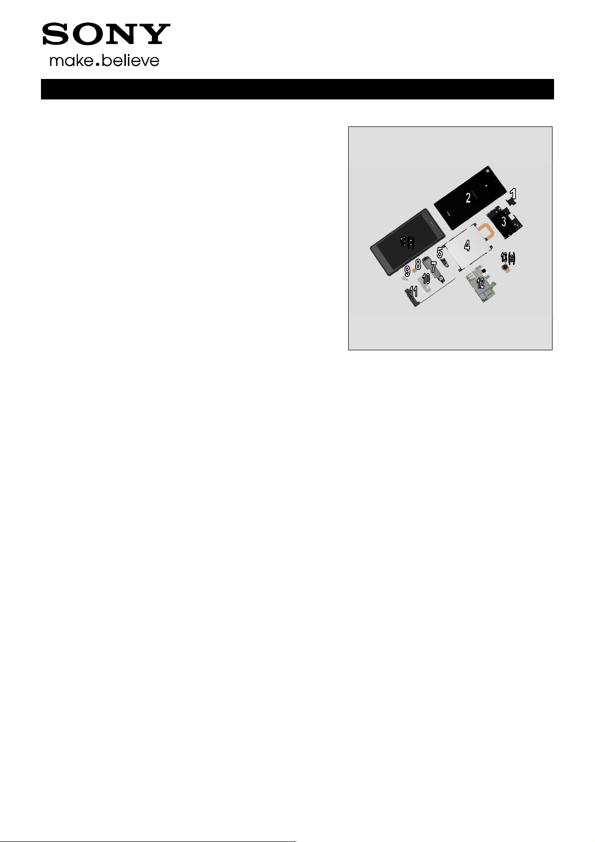
1 Exterior Views
1.1 L39t/L39u
Working Instructions (mech)
1278-7506 Rev 6
Sony Mobile Communications AB –
6(116)
Company Internal
Exterior Views
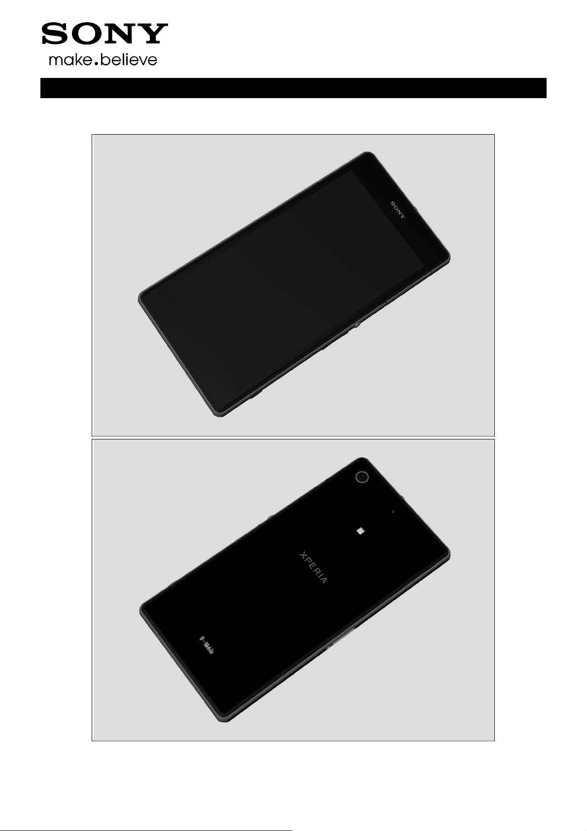
1.2 C6916
Working Instructions (mech)
1278-7506 Rev 6
Sony Mobile Communications AB –
7(116)
Company Internal
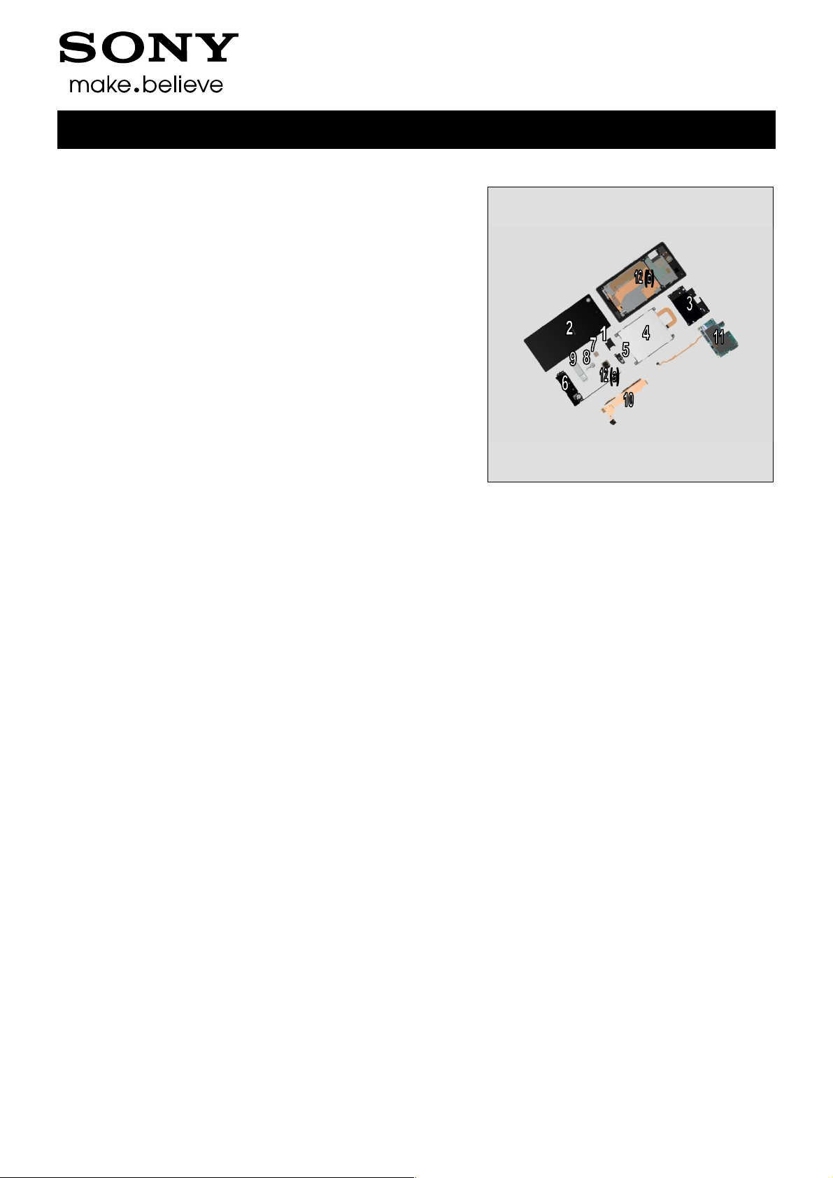
2 Tools
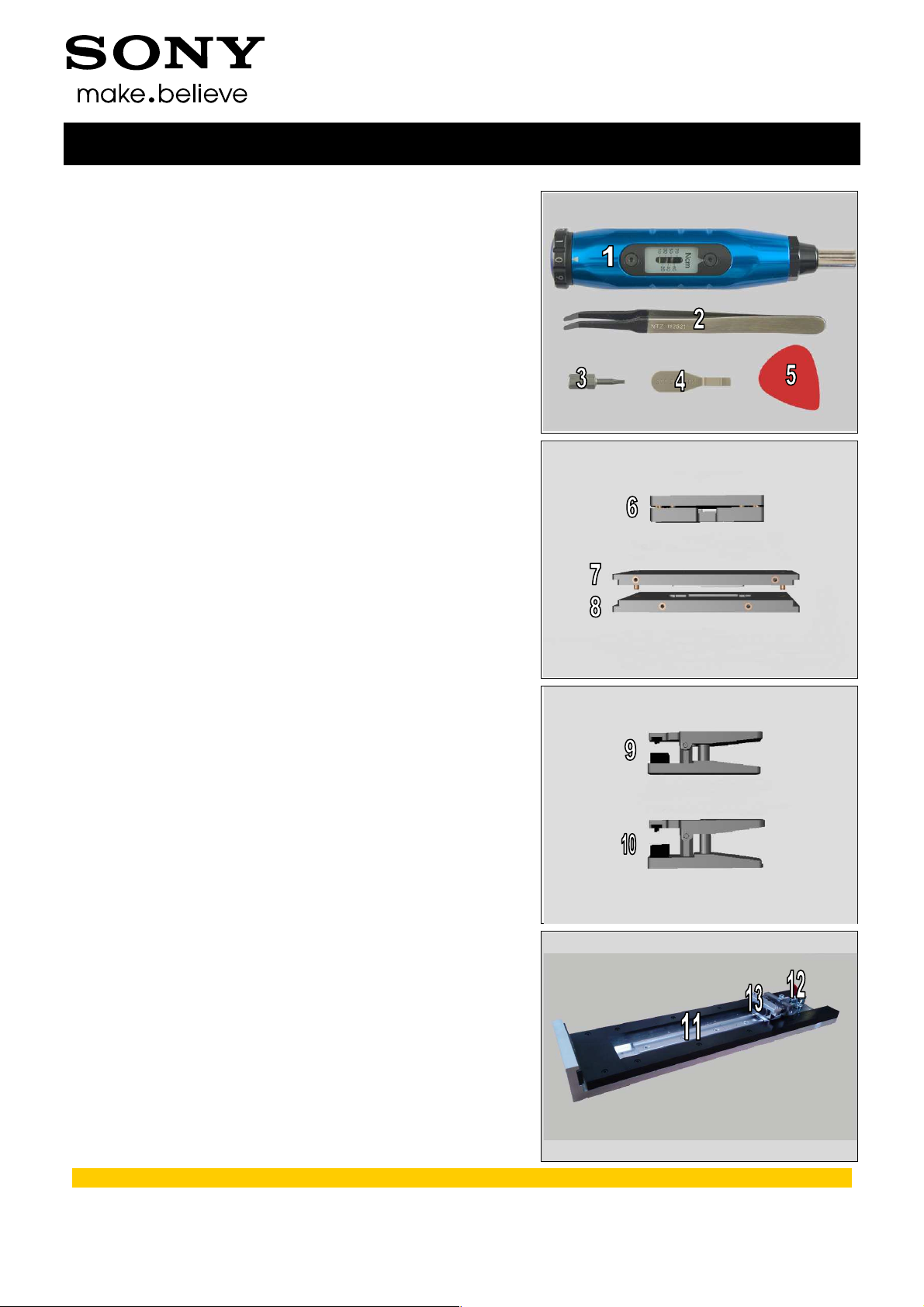
SPECIAL TOOLS
1. Torque Screwdriver
2. Flex Film Assembly Tool
3. Torx Bits T4
4. Front Opening Tool
5. Guitar Pick
6. Window Back Adhesive Fixture
7. Window Back Press Top Inlay
8. Bottom Press Inlay
Working Instructions (mech)
9. Earspeaker Press Tool
10. Audio Jack Press Tool
11. Side Panel press
12. Side Panel Press Head
13. Charge connector press pad
For part no’s on the tools above, refer to the ‘Tools Catalogue/Matrix’!
1278-7506 Rev 6
Sony Mobile Communications AB –
8(116)
Company Internal
Tools
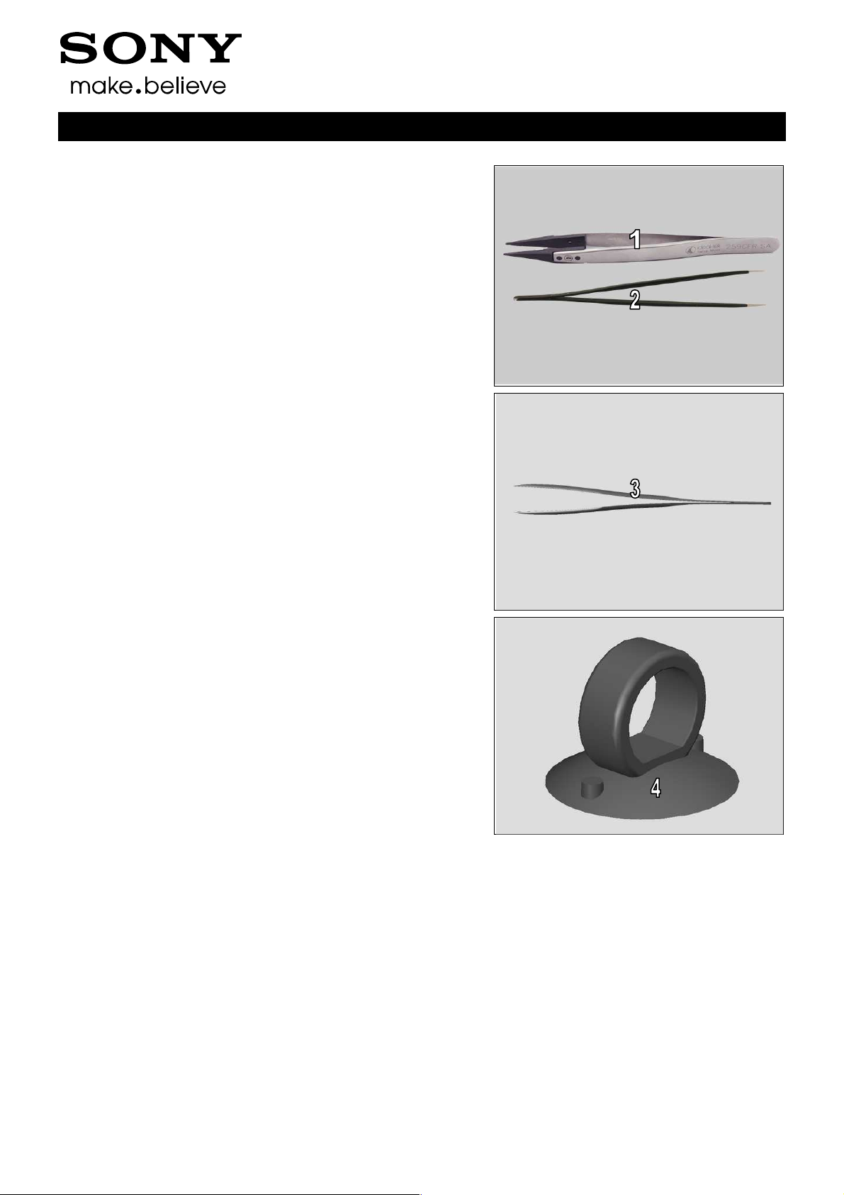
STANDARD TOOLS
1. Plastic Tweezers
2. Pointed-tip Tweezers
Working Instructions (mech)
3. Blunt-tip Tweezers
4. Suction cup
1278-7506 Rev 6
Sony Mobile Communications AB –
9(116)
Company Internal
3 Disassembly
3.1 Disassembly-L39t/L39u Specific
The L39t/L39u disassembly is done in the following order:
1. SIM Tray
2. Window Back Sub Assy
3. Sub Antenna Assy
4. Battery
5. Holder FPC Assy Audio Jack
6. Main Antenna Speaker Sub Assy & RF Cable & PBA
Sub
7. Tape Vibrator Connector
8. Vibrator
9. Shield Can LCD Component
10. FPC Assy Relay/Side Key
11. Main PBA & FPC Assy 2nd Antenna
12. Camera & Camera Holder (a) and Display Frame Assy
(b)
Working Instructions (mech)
1278-7506 Rev 6
Sony Mobile Communications AB –
10(116)

Company Internal
Disassembly
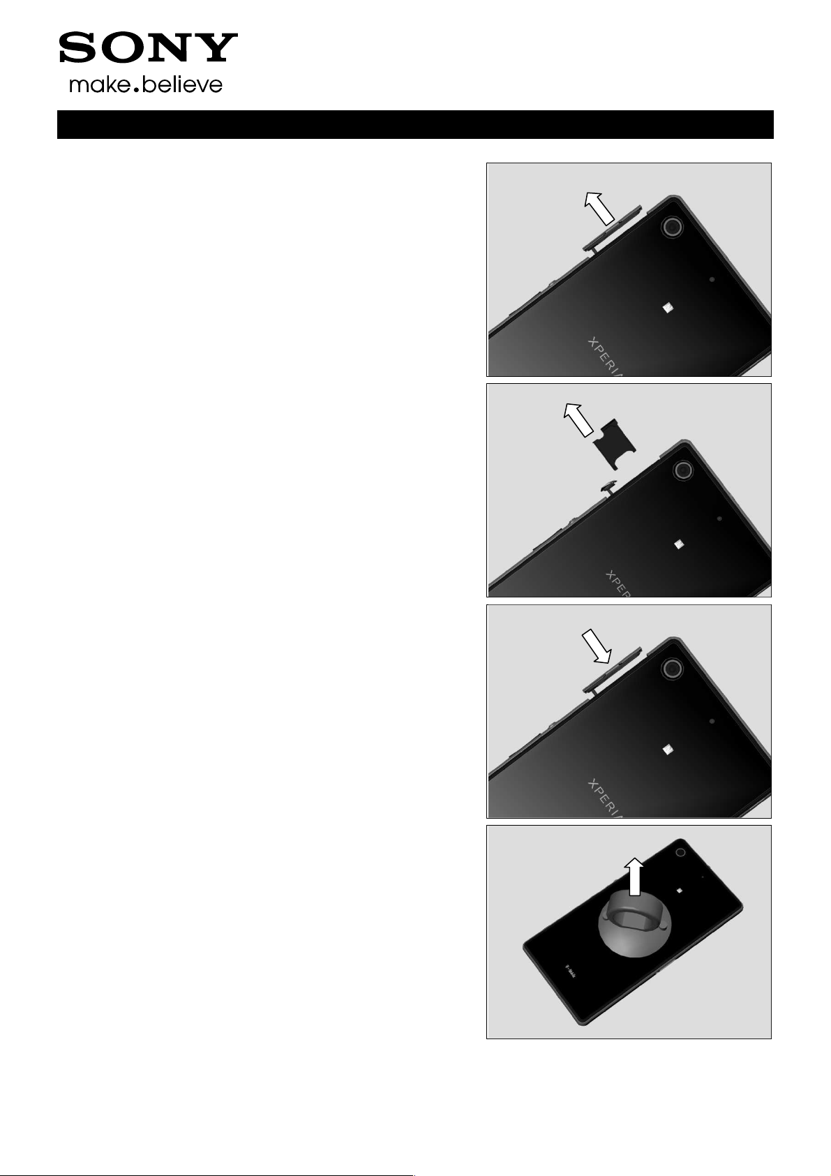
3.1.1 SIM Tray
Open the Cap SIM.
Remove the SIM Tray with fingers.
Working Instructions (mech)
Close the Cap SIM.
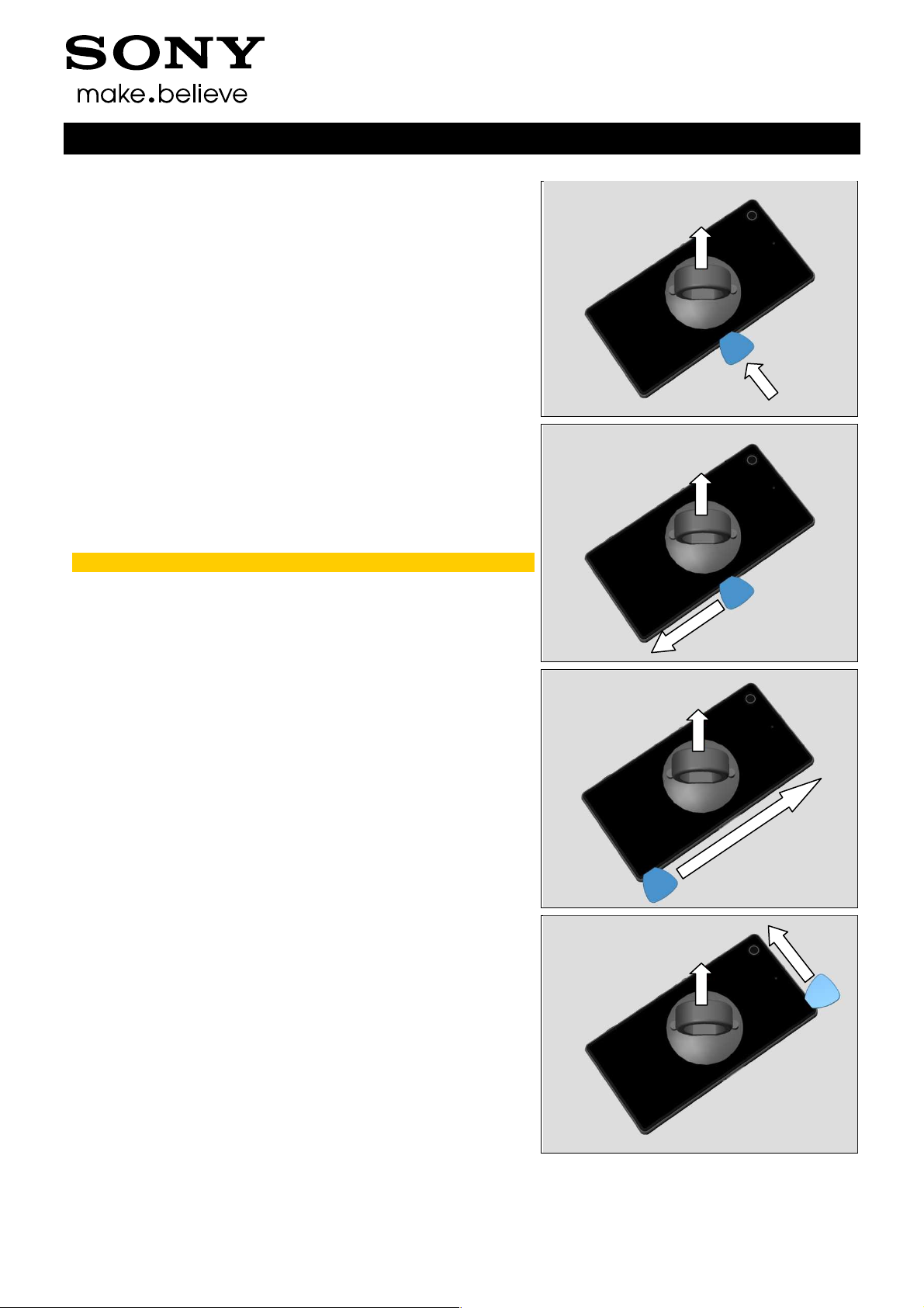
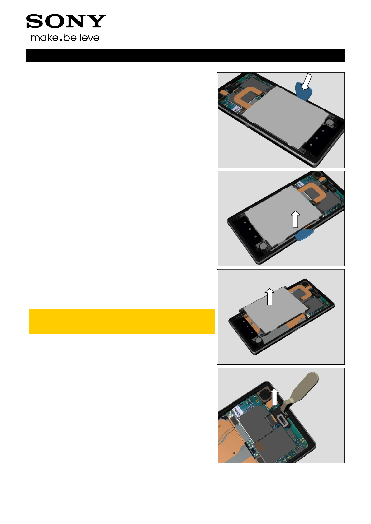
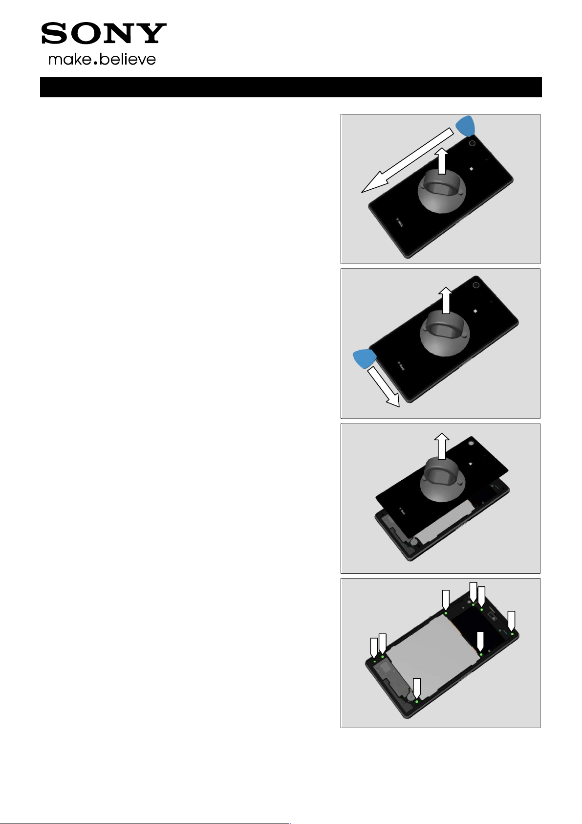
3.1.2 Window Back Sub Assy
Use Suction Cup to get space for inserting the Guitar Pick.
1278-7506 Rev 6
Sony Mobile Communications AB –
11(116)
Company Internal
Disassembly
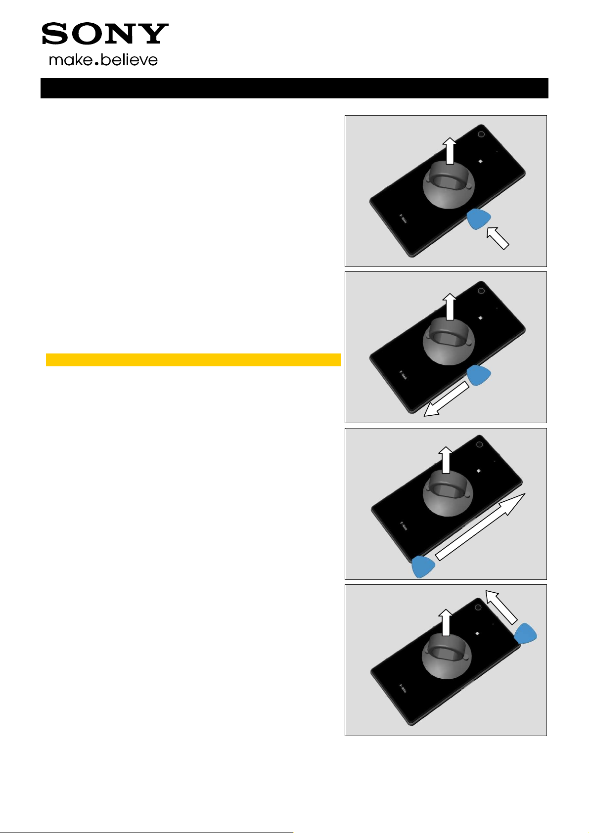
Insert the Guitar Pick.
Gently slide the Guitar Pick along to release all sides of the
Window Back Sub Assy.
Note! Start in the middle of the right long side!
Working Instructions (mech)
Do the same.
Do the same.
1278-7506 Rev 6
Sony Mobile Communications AB –
12(116)
Company Internal
Disassembly
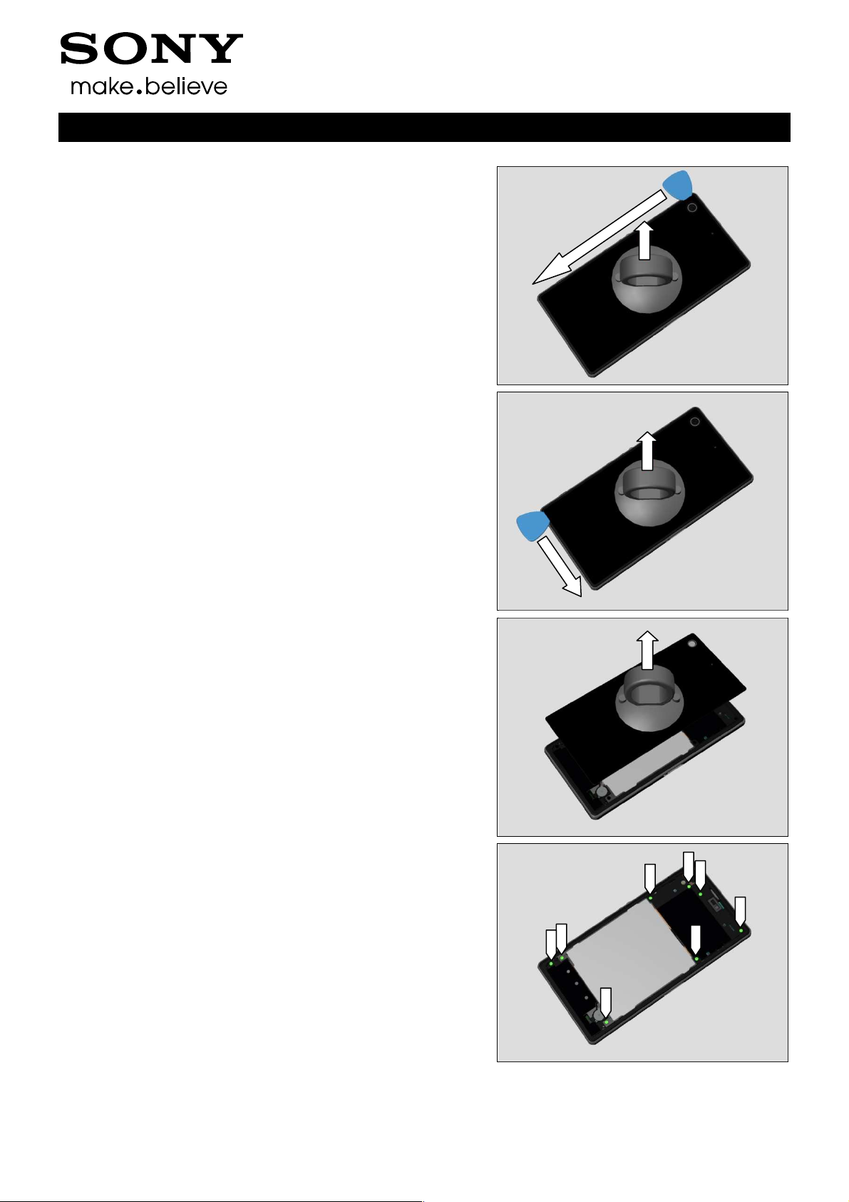
Do the same.
Do the same.
Working Instructions (mech)
Remove the Window Back Sub Assy by using the Suction
Cup.
3.1.3 Sub Antenna Assy
Remove the eight Screw Other Len:4.0 Diam:1.4 by using a
screwdriver with Torx Bits T4.
1278-7506 Rev 6
Sony Mobile Communications AB –
13(116)
Company Internal
Disassembly
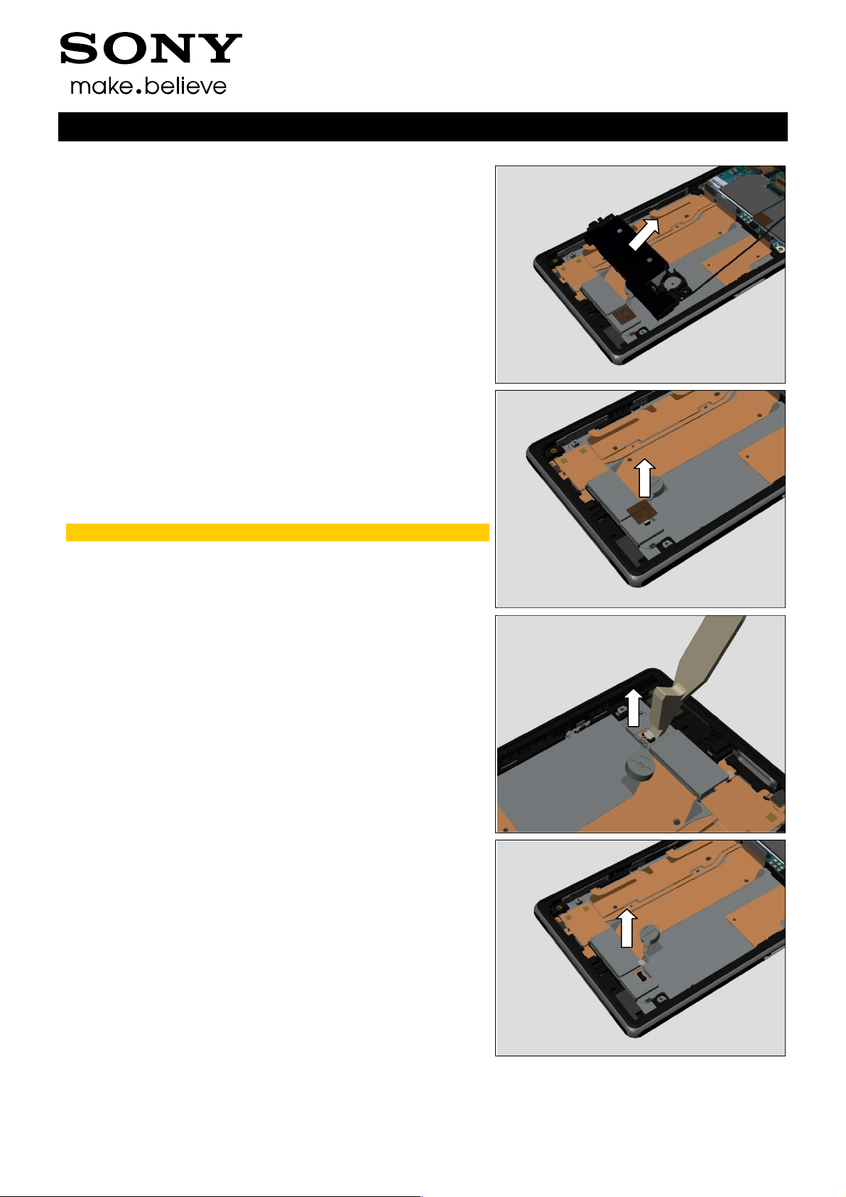
Release the hooks by using Guitar Pick and lift up the Sub
Antenna Assy from bottom side.
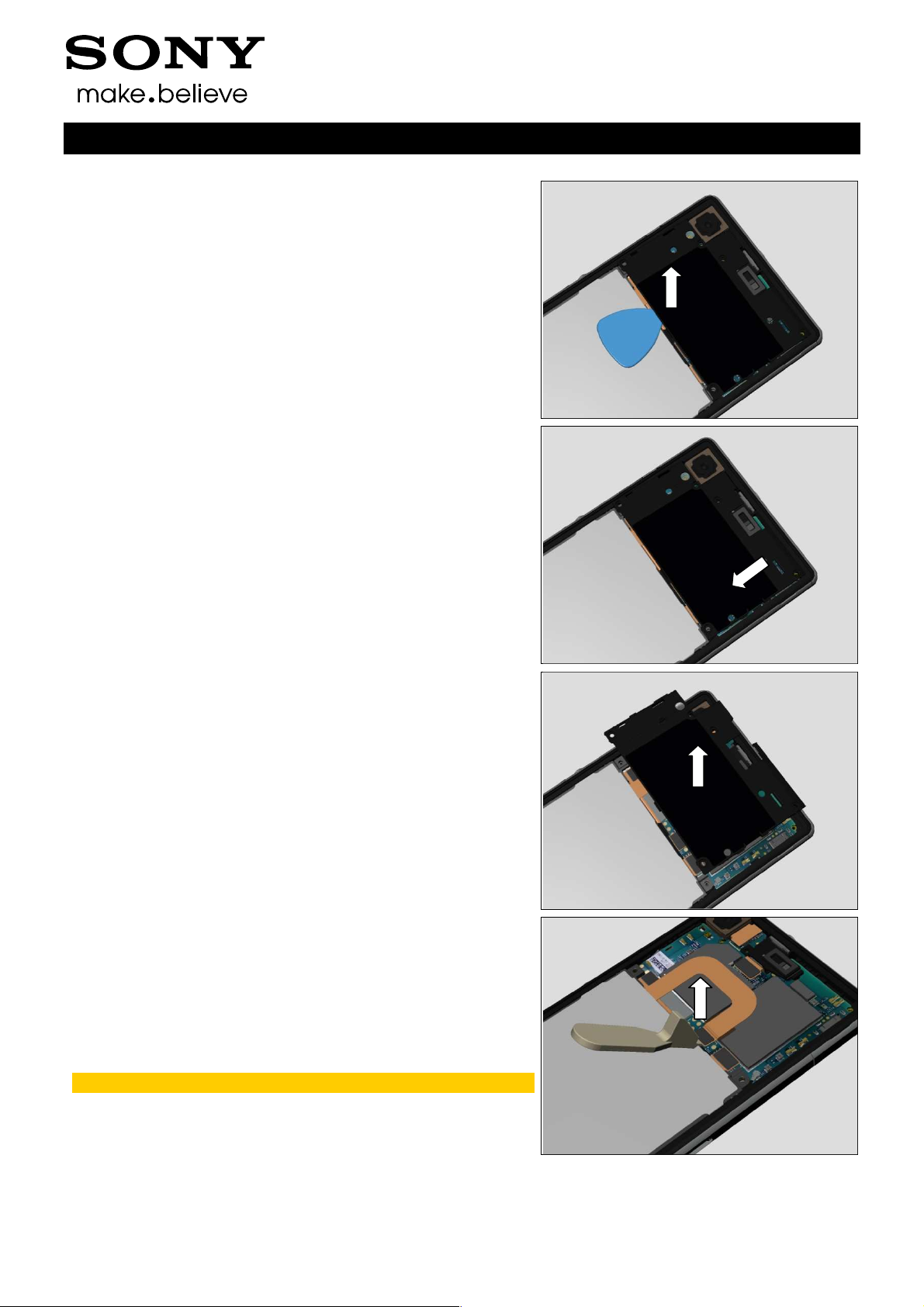
Release top right side of the Sub Antenna Assy as shown in
picture.
Working Instructions (mech)
Remove the Sub Antenna Assy.
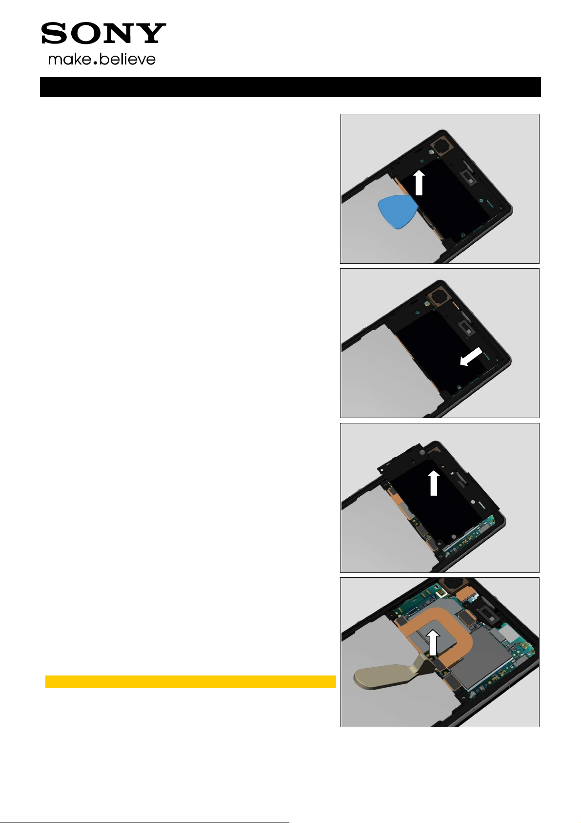
3.1.4 Battery
Disconnect the Battery FPC BtB connector by using the
Front Opening Tool.
Do not damage components on the Main PBA!
1278-7506 Rev 6
Sony Mobile Communications AB –
14(116)
Company Internal
Disassembly
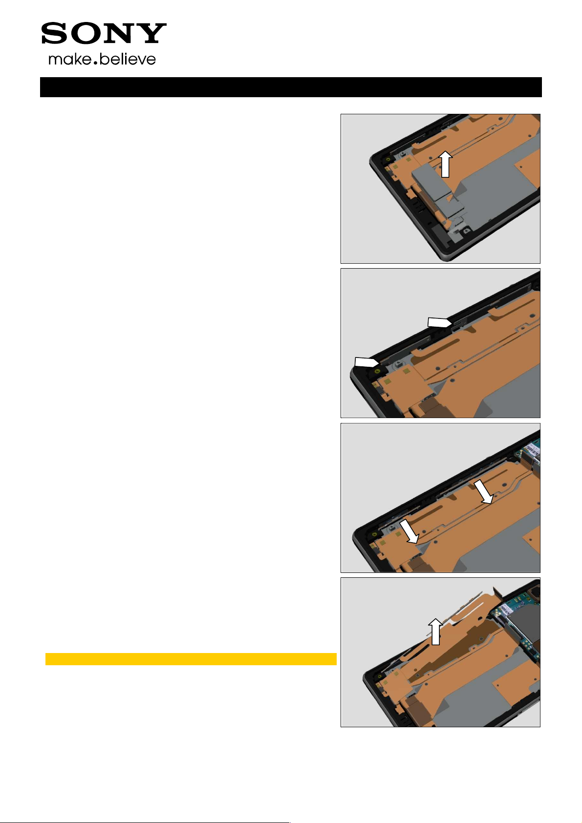
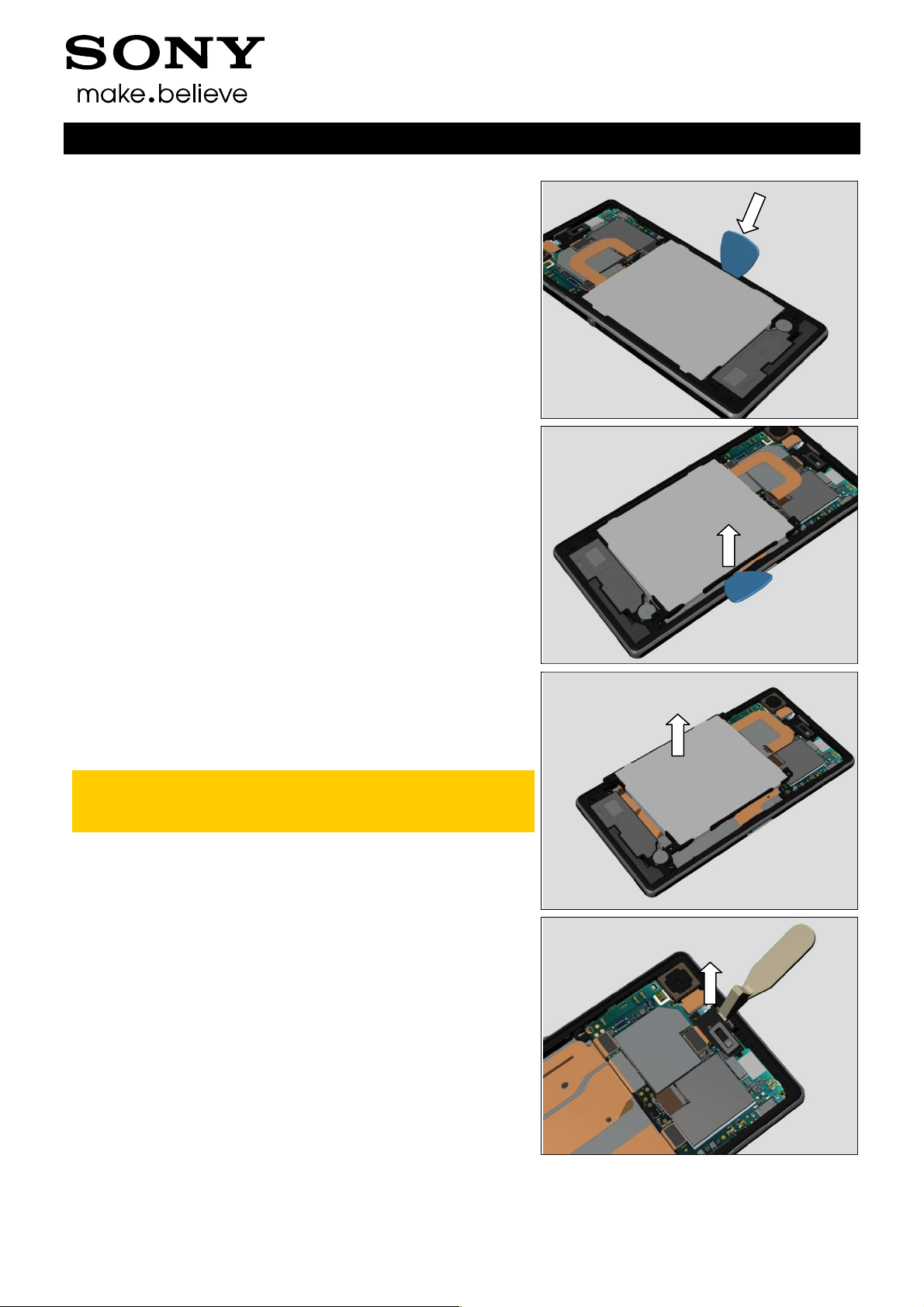
Insert Guitar Pick between the Battery and the Display
Frame Assy.
Gently release the Battery from its cavity.
Working Instructions (mech)
Remove the Battery.
Carefully inspect the Battery after removing it.
Battery with visual signs of been punctured etc, then
should be scraped after removal!
3.1.5 Holder FPC Assy Audio Jack
Unsnap the Holder FPC Assy Audio Jack by using the Front
Opening Tool.
1278-7506 Rev 6
Sony Mobile Communications AB –
15(116)
Company Internal
Disassembly
Remove it.
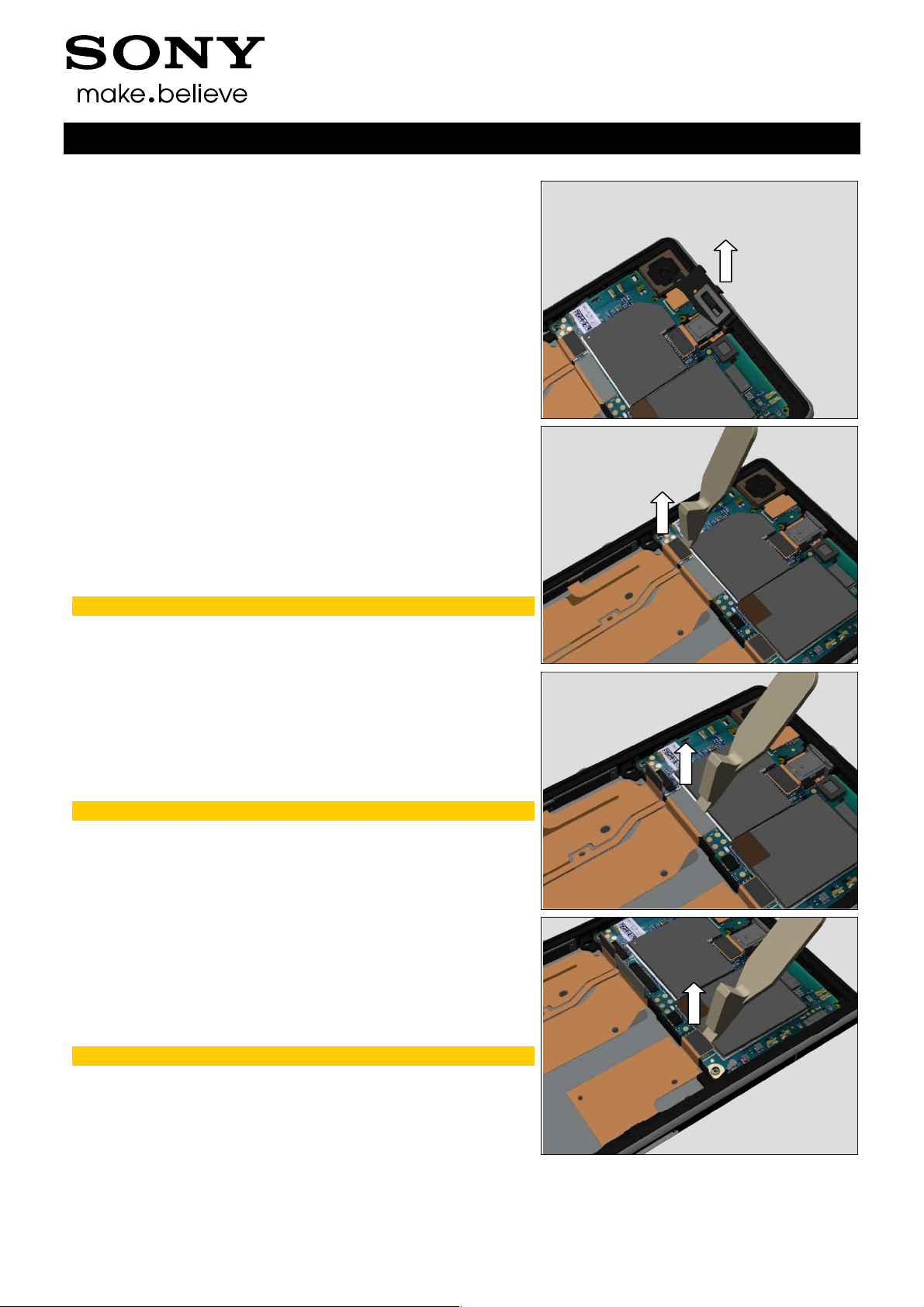
3.1.6 Main Antenna Speaker Sub
Assy & RF Cable & PBA Sub
Disconnect BtB connector of the FPC Assy Relay/Side Key
by using the Front Opening Tool.
Do not damage components on the Main PBA!
Working Instructions (mech)
Disconnect BtB connector of the Display FPC by using the
Front Opening Tool.
Do not damage components on the Main PBA!
Disconnect BtB connector of the FPC Assy Charger Pad by
using the Front Opening Tool.
Do not damage components on the Main PBA!
1278-7506 Rev 6
Sony Mobile Communications AB –
16(116)
Company Internal
Disassembly
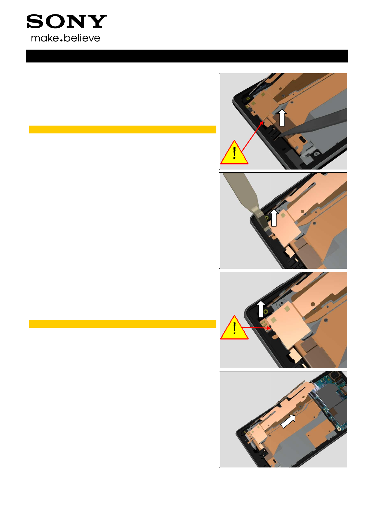
Disconnect BtB connector of the FPC Assy Audio Jack by
using the Front Opening Tool.
Do not damage components on the Main PBA!
Disconnect BtB connector of the Camera FPC by using the
Front Opening Tool.
Do not damage components on the Main PBA!
Working Instructions (mech)
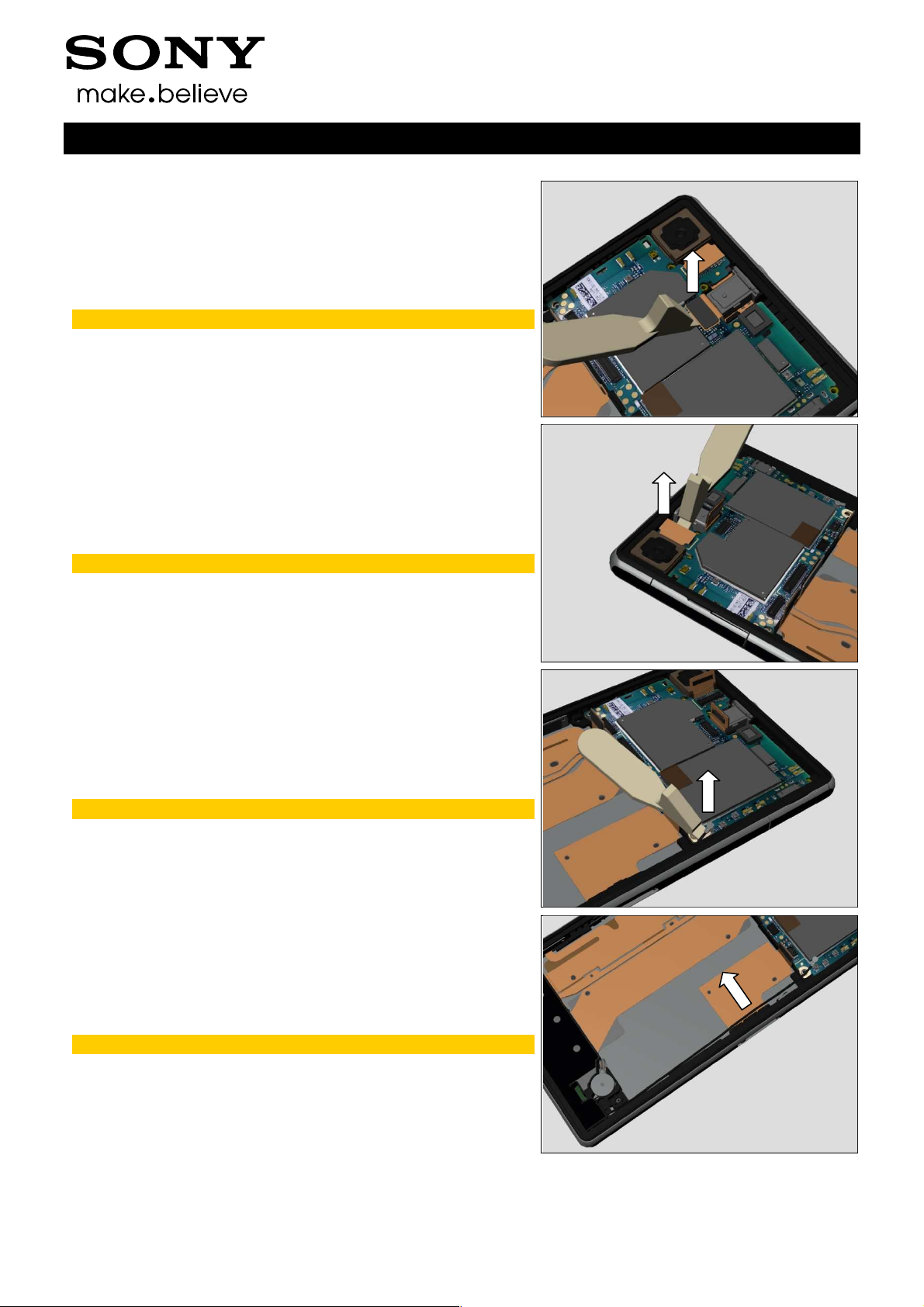
Disconnect RF Cable connector by using the Front Opening
Tool.
Do not damage components on the Main PBA!
Release the RF cable from the Plate Contact RF A.
Do not stretch the RF Cable!
1278-7506 Rev 6
Sony Mobile Communications AB –
17(116)
Company Internal
Disassembly
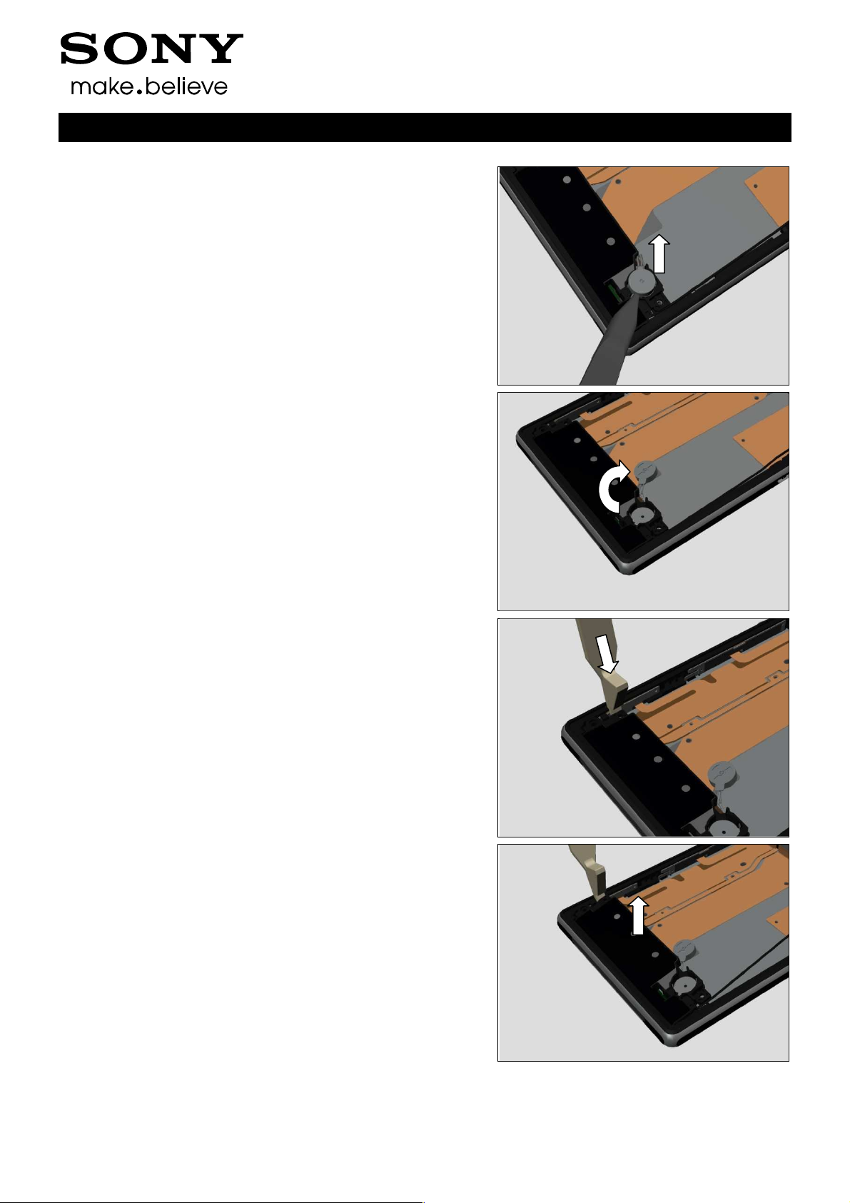
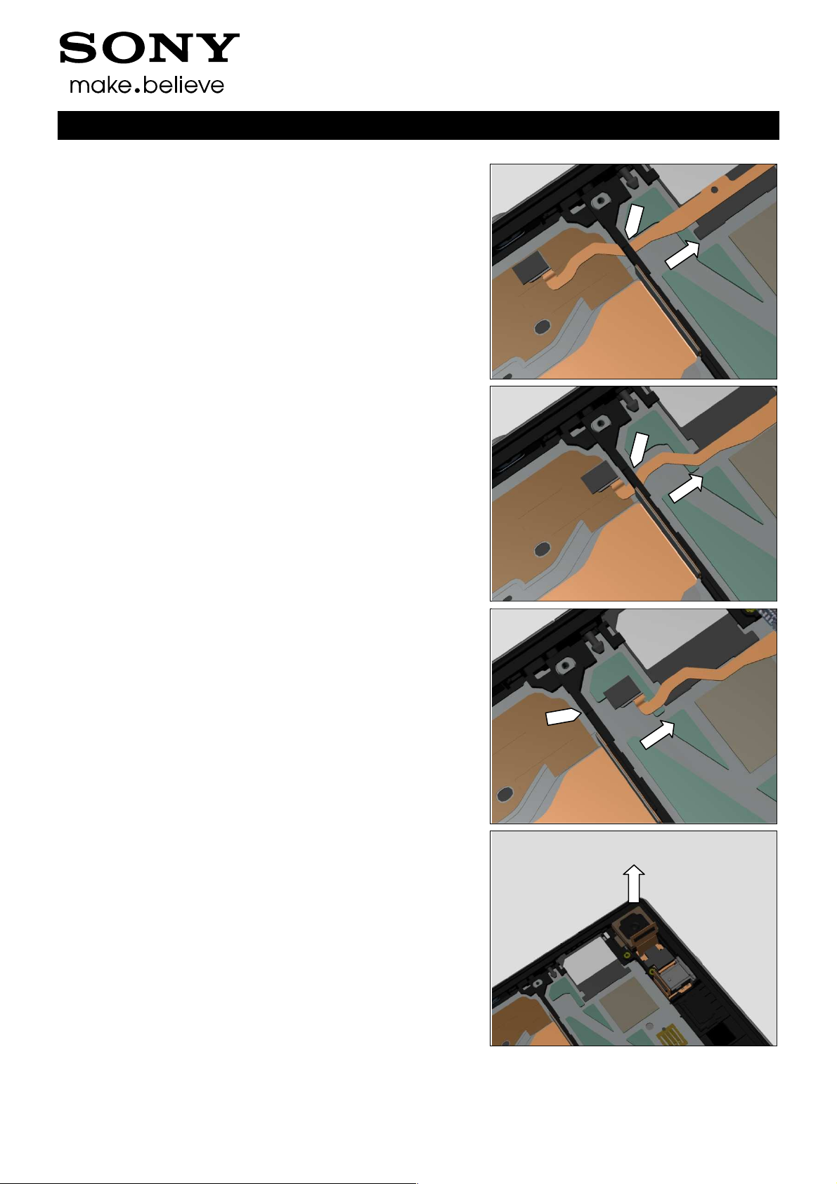
Release the Vibrator by using the Plastic Tweezers.
Rotate the Vibrator as shown in picture.
Working Instructions (mech)
Insert Front Opening Tool between the Main Antenna
Speaker Sub Assy and the Display Frame Assy.
Release the hooks of the Main Antenna Speaker Sub Assy.
1278-7506 Rev 6
Sony Mobile Communications AB –
18(116)
Company Internal
Disassembly
Remove the Main Antenna Speaker Sub Assy.
3.1.7 Tape Vibrator Connector
Detach the Tape Vibrator Connector.
Scrap! Not to be reused!
Working Instructions (mech)
3.1.8 Vibrator
Disconnect Vibrator connector by using the Front Opening
Tool.
Remove the Vibrator.
1278-7506 Rev 6
Sony Mobile Communications AB –
19(116)
Company Internal
Disassembly
3.1.9 Shield Can LCD Component
Detach and remove the Shield Can LCD Component.
3.1.10 FPC Assy Relay/Side Key
Identify the release positions as shown in picture.
Working Instructions (mech)
Release the side key FPC and camera key FPC by using
Plastic Tweezers.
Detach the FPC Assy Relay/Side Key as shown in picture.
Do not damage and fold the FPC!
1278-7506 Rev 6
Sony Mobile Communications AB –
20(116)
Sony Mobile Communications AB
Disassembly
FPC Assy Relay/Side Key
FPC!
Disconnect RF connector of the FPC Assy 2nd Antenna.
FPC Assy
FPC!
FPC Assy Relay/Side Key
Working Instructions (mech)
Company Internal
Release 1st MIC part of the
shown in picture.
Be careful! Do not break the
as
Detach RF connector part of the
Be careful! Do not break the
Remove the
1278-7506 Rev 6
–
Relay/Side Key.
.
21(116)
Company Internal
Disassembly
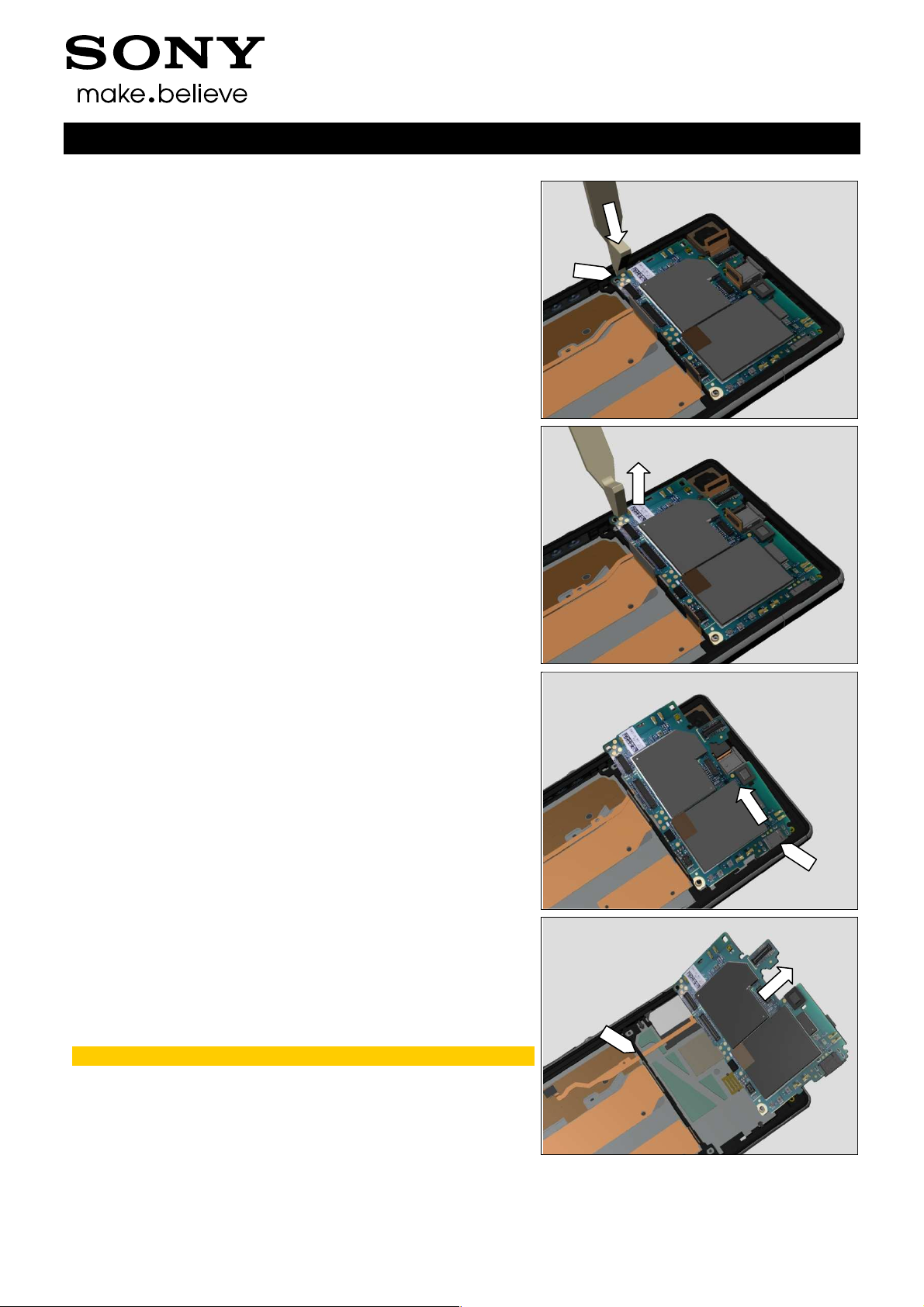
3.1.11 Main PBA & FPC Assy 2nd
Antenna
Insert the Front Opening Tool at this position as shown in
picture.
Release the Main PBA.
Working Instructions (mech)
Move the Main PBA as shown in picture until the USB
connector is visible.
Lift up the Main PBA and carefully thread the FPC Assy 2nd
Antenna through the hole as shown in picture.
Do not damage the FPC when threading!
1278-7506 Rev 6
Sony Mobile Communications AB –
22(116)
Company Internal
Disassembly
Continue threading as shown in picture.
Continue threading as shown in picture.
Working Instructions (mech)
Continue threading as shown in picture.
3.1.12 Camera & Camera Holder (a)
and Display Frame Assy (b)
Remove the Camera and its Camera Holder.
1278-7506 Rev 6
Sony Mobile Communications AB –
23(116)
Company Internal
Disassembly
3.2 Disassembly-C6916 Specific
The C6916 disassembly is done in the following order:
1. SIM Tray
2. Window Back Sub Assy
3. Sub Antenna Assy
4. Battery
5. Holder FPC Assy Audio Jack
6. Disassemble RF Cable from Main PBA and Display
Frame Assy
7. Speaker Sub Assy
8. Tape Vibrator Connector
9. Vibrator
10. Shield Can LCD Component
11. Main Antenna Assy & RF Cable & PBA Sub
12. Main PBA
13. Camera & Camera Holder (a) and Display Frame Assy
(b)
Working Instructions (mech)
1278-7506 Rev 6
Sony Mobile Communications AB –
24(116)
Company Internal
Disassembly
3.2.1 SIM Tray
Open the Cap SIM.
Remove the SIM Tray with fingers.
Working Instructions (mech)
Close the Cap SIM.
3.2.2 Window Back Sub Assy
Use Suction Cup to get space for inserting the Guitar Pick.
1278-7506 Rev 6
Sony Mobile Communications AB –
25(116)
Company Internal
Disassembly
Insert the Guitar Pick.
Gently slide the Guitar Pick along to release all sides of the
Window Back Sub Assy.
Note! Start in the middle of the right long side!
Working Instructions (mech)
Do the same.
Do the same.
1278-7506 Rev 6
Sony Mobile Communications AB –
26(116)
Company Internal
Disassembly
Do the same.
Do the same.
Working Instructions (mech)
Remove the Window Back Sub Assy by using the Suction
Cup.
3.2.3 Sub Antenna Assy
Remove the eight Screw Other Len:4.0 Diam:1.4 by using a
screwdriver with Torx Bits T4.
1278-7506 Rev 6
Sony Mobile Communications AB –
27(116)
Company Internal
Disassembly
Release the hooks by using Guitar Pick and lift up the Sub
Antenna Assy from bottom side.
Release top right side of the Sub Antenna Assy as shown in
picture.
Working Instructions (mech)
Remove the Sub Antenna Assy.
3.2.4 Battery
Disconnect the Battery FPC BtB connector by using the
Front Opening Tool.
Do not damage components on the Main PBA!
1278-7506 Rev 6
Sony Mobile Communications AB –
28(116)
Company Internal
Disassembly
Insert Guitar Pick between the Battery and the Display
Frame Assy.
Gently release the Battery from its cavity.
Working Instructions (mech)
Remove the Battery.
Carefully inspect the Battery after removing it.
Battery with visual signs of been punctured etc, then
should be scraped after removal!
3.2.5 Holder FPC Assy Audio Jack
Unsnap the Holder FPC Assy Audio Jack by using the Front
Opening Tool.
1278-7506 Rev 6
Sony Mobile Communications AB –
29(116)

Company Internal
Disassembly
Remove it.
3.2.6 Disassemble RF Cable from
Main PBA and Display Frame
Assy
Disconnect RF Cable connector by using the Front Opening
Tool.
Do not damage components on the Main PBA!
Working Instructions (mech)
Release the RF cable from the Plate Contact RF A.
Do not stretch the RF Cable!
3.2.7 Speaker Sub Assy
Release the Vibrator by using the Plastic Tweezers.
1278-7506 Rev 6
Sony Mobile Communications AB –
30(116)

Company Internal
Disassembly
Rotate the Vibrator as shown in picture.
Insert Front Opening Tool between the Speaker Sub Assy
and the Display Frame Assy.
Working Instructions (mech)
Release the hooks of the Speaker Sub Assy.
Remove the Speaker Sub Assy.
1278-7506 Rev 6
Sony Mobile Communications AB –
31(116)

Company Internal
Disassembly
3.2.8 Tape Vibrator Connector
Detach the Tape Vibrator Connector.
Scrap! Not to be reused!
3.2.9 Vibrator
Disconnect Vibrator connector by using the Front Opening
Tool.
Working Instructions (mech)
Remove the Vibrator.
3.2.10 Shield Can LCD Component
Detach and remove the Shield Can LCD Component.
1278-7506 Rev 6
Sony Mobile Communications AB –
32(116)

Sony Mobile Communications AB
Disassembly
Main Antenna Assy
as shown in picture.
Be careful! Press and hold down the Display FPC to
the Main Antenna
FPC Assy Relay/Side Key
Do not damage components on
Display FPC
Do not damage components on
Working Instructions (mech)
Company Internal
3.2.11
& PBA Sub
Rotate the Main Antenna Assy
avoid contact with
rotating.
Remove the Main Antenna Assy.
& RF Cable
Assy when
3.2.12 Main PBA
Disconnect BtB connector of the
by using the Front Opening Tool.
Disconnect BtB connector of the
Front Opening Tool.
the Main PBA!
by using the
the Main PBA!
1278-7506 Rev 6
–
33(116)

Company Internal
Disassembly
Disconnect BtB connector of the FPC Assy Charger Pad by
using the Front Opening Tool.
Do not damage components on the Main PBA!
Disconnect BtB connector of the FPC Assy Audio Jack by
using the Front Opening Tool.
Do not damage components on the Main PBA!
Working Instructions (mech)
Disconnect BtB connector of the Camera FPC by using the
Front Opening Tool.
Do not damage components on the Main PBA!
Insert the Front Opening Tool at this position as shown in
picture.
1278-7506 Rev 6
Sony Mobile Communications AB –
34(116)

Company Internal
Disassembly
Release the Main PBA.
Move the Main PBA as shown in picture until the USB
connector is visible.
Working Instructions (mech)
Remove the Main PBA.
3.2.13 Camera & Camera Holder (a)
and Display Frame Assy (b)
Remove the Camera and its Camera Holder.
1278-7506 Rev 6
Sony Mobile Communications AB –
35(116)

Company Internal
4 Replacement
4.1 Battery
L39t/L39u Follow the 3.1.2 – 3.1.4 Disassembly instructions!
C6916 Follow the 3.2.2 – 3.2.4 Disassembly instructions!
Prepare a new Battery.
L39t/L39u Follow the 5.1.9 – 5.1.11 Reassembly instructions!
C6916 Follow the 5.2.10 – 5.2.12 Reassembly instructions!
4.2 Camera
L39t/L39u Follow the 3.1.1 – 3.1.12 Disassembly instructions!
C6916 Follow the 3.2.1 – 3.2.13 Disassembly instructions!
Follow the 4.29 Removal instructions!
Prepare a new Camera.
Follow the 4.29 Installation instructions!
L39t/L39u Follow the 5.1.1 – 5.1.12 Reassembly instructions!
C6916 Follow the 5.2.1 – 5.2.13 Reassembly instructions!
Working Instructions (mech)
4.3 Display Frame Assy-
L39t/L39u Specific
L39t/L39u Follow the 3.1.1 – 3.1.12 Disassembly instructions!
Follow the 4.47, 4.42 and 4.57 Removal instructions!
Prepare a new Display Frame Assy.
Follow the 4.42, 4.47 and 4.57 Installation instructions!
L39t/L39u Follow the 5.1.1 – 5.1.12 Reassembly instructions!
Touch panel calibration must be performed for all
replaced units; 1257-2706 Trouble Shooting Application
– mechanical.
4.4 Display Frame Assy-
C6916 Specific
C6916 Follow the 3.2.1 – 3.2.13 Disassembly instructions!
Follow the 4.47, 4.42, 4.43 and 4.57 Removal instructions!
Prepare a new Display Frame Assy.
Follow the 4.42, 4.47, 4.43 and 4.57 Installation instructions!
C6916 Follow the 5.2.1 – 5.2.13 Reassembly instructions!
Touch panel calibration must be performed for all
replaced units; 1257-2706 Trouble Shooting Application
– mechanical.
1278-7506 Rev 6
Sony Mobile Communications AB –
36(116)

Company Internal
Replacement
4.5 FPC Assy Relay/Side Key-
L39t/L39u Specific
L39t/L39u Follow the 3.1.2 – 3.1.10 Disassembly instructions!
Prepare a new FPC Assy Relay/Side Key.
L39t/L39u Follow the 5.1.3 – 5.1.11 Reassembly instructions!
Scrap when the FPC is damage or folded!
Follow the 4.23 Removal and Installation instructions to
replace a new Adhesive Relay FPC.
4.6 Holder FPC Assy Audio
Jack-L39t/L39u Specific
L39t/L39u Follow the 3.1.2 – 3.1.5 Disassembly instructions!
Prepare a new Holder FPC Assy Audio Jack.
Follow the 4.46 Installation instructions!
L39t/L39u Follow the 5.1.8 – 5.1.11 Reassembly instructions!
Working Instructions (mech)
4.7 Holder FPC Assy Audio
Jack-C6916 Specific
C6916 Follow the 3.2.2 – 3.2.5 Disassembly instructions!
Prepare a new Holder FPC Assy Audio Jack.
C6916 Follow the 5.2.9– 5.2.12 Reassembly instructions!
4.8 Main Antenna Assy-C6916
Specific
C6916 Follow the 3.2.2 – 3.2.11 Disassembly instructions!
Follow the 4.52 and 4.55 Removal instructions!
Prepare a new Main Antenna Assy.
Follow the 4.55 and 4.52 Installation instructions!
C6916 Follow the 5.2.3 – 5.2.12 Reassembly instructions!
1278-7506 Rev 6
Sony Mobile Communications AB –
37(116)

Company Internal
Replacement
4.9 Main Antenna Speaker
Sub Assy- L39t/L39u
Specific
L39t/L39u Follow the 3.1.2 – 3.1.6 Disassembly instructions!
Follow the 4.51 and 4.55 Removal instructions!
Prepare a new Main Antenna Speaker Sub Assy.
Follow the 4.55 and 4.51 Installation instructions!
L39t/L39u Follow the 5.1.7 – 5.1.11 Reassembly instructions!
4.10 Shield Can LCD
Component
L39t/L39u Follow the 3.1.2 – 3.1.9 Disassembly instructions!
C6916 Follow the 3.2.2 – 3.2.10 Disassembly instructions!
Prepare a new Shield Can LCD Component.
L39t/L39u
applicable for C6916)
L39t/L39u Follow the 5.1.4 – 5.1.11 Reassembly instructions!
C6916 Follow the 5.2.4 – 5.2.12 Reassembly instructions!
Follow the 4.39 Installation instructions! (not
Working Instructions (mech)
4.11 SIM Tray
L39t/L39u Follow the 3.1.1 Disassembly instructions!
C6916 Follow the 3.2.1 Disassembly instructions!
Prepare a new SIM Tray.
L39t/L39u Follow the 5.1.12 Reassembly instructions!
C6916 Follow the 5.2.13 Reassembly instructions!
4.12 Speaker Sub Assy- C6916
Specific
C6916 Follow the 3.2.2 – 3.2.7 Disassembly instructions!
Prepare a new Speaker Sub Assy.
C6916 Follow the 5.2.7 – 5.2.12 Reassembly instructions!
1278-7506 Rev 6
Sony Mobile Communications AB –
38(116)

Company Internal
Replacement
4.13 Sub Antenna Assy
L39t/L39u Follow the 3.1.2 – 3.1.3 Disassembly instructions!
C6916 Follow the 3.2.2 – 3.2.3 Disassembly instructions!
L39t/L39u
applicable for C6916)
Prepare a new Sub Antenna Assy.
L39t/L39u
applicable for C6916)
L39t/L39u Follow the 5.1.10 – 5.1.11 Reassembly instructions!
C6916 Follow the 5.2.11 – 5.2.12 Reassembly instructions!
Follow the 4.53 Removal instructions! (not
Follow the 4.53 Installation instructions! (not
4.14 Tape Vibrator Connector
L39t/L39u Follow the 3.1.2 – 3.1.7 Disassembly instructions!
C6916 Follow the 3.2.2 – 3.2.8 Disassembly instructions!
Prepare a new Tape Vibrator Connector.
L39t/L39u Follow the 5.1.6 – 5.1.11 Reassembly instructions!
C6916 Follow the 5.2.6 – 5.2.12 Reassembly instructions!
Scrap! Not to be reused!
Working Instructions (mech)
4.15 Vibrator
L39t/L39u Follow the 3.1.2 – 3.1.8 Disassembly instructions!
C6916 Follow the 3.2.2 – 3.2.9 Disassembly instructions!
Prepare a new Vibrator.
L39t/L39u Follow the 5.1.5 – 5.1.11 Reassembly instructions!
C6916 Follow the 5.2.5 – 5.2.12 Reassembly instructions!
4.16 Window Back Sub Assy
L39t/L39u Follow the 3.1.2 Disassembly instructions!
C6916 Follow the 3.2.2 Disassembly instructions!
Prepare a new Window Back Sub Assy.
L39t/L39u Follow the 5.1.11 Reassembly instructions!
C6916 Follow the 5.2.12 Reassembly instructions!
1278-7506 Rev 6
Sony Mobile Communications AB –
39(116)

Company Internal
Replacement
4.17 Adhesive Camera Key FPC Left
L39t/L39u Follow the 3.1.2 – 3.1.10 Disassembly instructions!
C6916 Follow the 3.2.2 – 3.2.11 Disassembly instructions!
C6916
applicable for L39t/L39u)
Prepare a new Adhesive Camera Key FPC Left.
C6916
applicable for L39t/L39u)
L39t/L39u Follow the 5.1.3 – 5.1.11 Reassembly instructions!
C6916 Follow the 5.2.3 – 5.2.12 Reassembly instructions!
REMOVAL
Detach the Adhesive Camera Key FPC Left and remove it
with a pair of Plastic Tweezers.
Scrap! Not to be reused!
Follow the 4.43 Removal instructions! (not
Follow the 4.43 Installation instructions! (not
Working Instructions (mech)
INSTALLATION
Attach a new Adhesive Camera Key FPC Left aligning with
the guiding hole by using a pair of Plastic Tweezers as
shown in picture.
1278-7506 Rev 6
Sony Mobile Communications AB –
40(116)

Company Internal
Replacement
4.18 Adhesive Camera Key FPC Right
L39t/L39u Follow the 3.1.2 – 3.1.10 Disassembly instructions!
C6916 Follow the 3.2.2 – 3.2.11 Disassembly instructions!
C6916
applicable for L39t/L39u)
Prepare a new Adhesive Camera Key FPC Right.
C6916
applicable for L39t/L39u)
L39t/L39u Follow the 5.1.3 – 5.1.11 Reassembly instructions!
C6916 Follow the 5.2.3 – 5.2.12 Reassembly instructions!
REMOVAL
Detach the Adhesive Camera Key FPC Right and remove it
with a pair of Plastic Tweezers.
Scrap! Not to be reused!
Follow the 4.43 Removal instructions! (not
Follow the 4.43 Installation instructions! (not
Working Instructions (mech)
INSTALLATION
Attach a new 2nd MIC Mesh in its proper position by using a
pair of Plastic Tweezers as shown in picture.
1278-7506 Rev 6
Sony Mobile Communications AB –
41(116)

Company Internal
Replacement
4.19 Adhesive Display FPC
L39t/L39u Follow the 3.1.2 – 3.1.10 Disassembly instructions!
C6916 Follow the 3.2.2 – 3.2.11 Disassembly instructions!
C6916
applicable for L39t/L39u)
Prepare a new Adhesive Display FPC.
C6916
applicable for L39t/L39u)
L39t/L39u Follow the 5.1.3 – 5.1.11 Reassembly instructions!
C6916 Follow the 5.2.3 – 5.2.12 Reassembly instructions!
REMOVAL
Disconnect BtB connector of the Display FPC, and then
detach the Display FPC with fingers.
Remove the Adhesive Display FPC by using a pair of Plastic
Tweezers.
Scrap! Not to be reused!
Make sure all remaining adhesive residue have been
removed!
Follow the 4.43 Removal instructions! (not
Follow the 4.43 Installation instructions! (not
Working Instructions (mech)
INSTALLATION
Attach a new Adhesive Display FPC aligning with the 3
guiding holes as shown in picture by using a pair of Plastic
Tweezers.
Attach the Display FPC aligning with the 2 guiding holes and
2 guiding lines as shown in picture.
Press to snap the Display FPC BtB connector.
1278-7506 Rev 6
Sony Mobile Communications AB –
42(116)

Company Internal
Working Instructions (mech)
Replacement
4.20 Adhesive Relay FPC Bottom-C6916 Specific
C6916 Follow the 3.2.2 – 3.2.11 Disassembly instructions!
Follow the 4.43 Removal instructions!
Prepare a new Adhesive Relay FPC Bottom.
Follow the 4.43 Installation instructions!
C6916 Follow the 5.2.3 – 5.2.12 Reassembly instructions!
REMOVAL
Detach the Adhesive Relay FPC Bottom and remove it with a
pair of Plastic Tweezers.
Scrap! Not to be reused!
Make sure all remaining adhesive residue have been
removed!
INSTALLATION
Attach a new Adhesive Relay FPC Bottom in its proper
position by using a pair of Plastic Tweezers as shown in
picture.
1278-7506 Rev 6
Sony Mobile Communications AB –
43(116)

Company Internal
Working Instructions (mech)
Replacement:
4.21 Adhesive Relay FPC RF Conn-L39t/L39u
Specific
L39t/L39u Follow the 3.1.2 – 3.1.10 Disassembly instructions!
Prepare a new Adhesive Relay FPC RF Conn.
L39t/L39u Follow the 5.1.3 – 5.1.11 Reassembly instructions!
REMOVAL
Detach the Adhesive Relay FPC RF Conn and remove it with
a pair of Plastic Tweezers.
Scrap! Not to be reused!
Make sure all remaining adhesive residue have been
removed!
Do not damage the components on the back side!
INSTALLATION
Attach a new Adhesive Relay FPC RF Conn in its proper
position by using a pair of Plastic Tweezers as shown in
picture.
1278-7506 Rev 6
Sony Mobile Communications AB –
44(116)

Company Internal
Working Instructions (mech)
Replacement
4.22 Adhesive Relay FPC Support -L39t/L39u
Specific
L39t/L39u Follow the 3.1.2 – 3.1.10 Disassembly instructions!
Prepare a new Adhesive Relay FPC Support.
L39t/L39u Follow the 5.1.3 – 5.1.11 Reassembly instructions!
REMOVAL
Detach the Adhesive Relay FPC Support and remove it with
a pair of Plastic Tweezers.
Scrap! Not to be reused!
Make sure all remaining adhesive residue have been
removed!
INSTALLATION
Attach a new Adhesive Relay FPC Support in its proper
position by using a pair of Plastic Tweezers as shown in
picture.
1278-7506 Rev 6
Sony Mobile Communications AB –
45(116)

Company Internal
Working Instructions (mech)
Replacement
4.23 Adhesive Relay FPC-L39t/L39u Specific
L39t/L39u Follow the 3.1.1 – 3.1.11 Disassembly instructions!
Prepare a new Adhesive Relay FPC.
L39t/L39u Follow the 5.1.2 – 5.1.12 Reassembly instructions!
REMOVAL
Remove the Adhesive Relay FPC by using a pair of Plastic
Tweezers.
Scrap! Not to be reused!
Make sure all remaining adhesive residue have been
removed!
INSTALLATION
Attach a new Adhesive Relay FPC aligning with the 2 guiding
holes as shown in picture by using a pair of Plastic Tweezers.
1278-7506 Rev 6
Sony Mobile Communications AB –
46(116)

Company Internal
Working Instructions (mech)
Replacement
4.24 Adhesive Relay FPC-C6916 Specific
C6916 Follow the 3.2.2 – 3.2.11 Disassembly instructions!
Follow the 4.43 Removal instructions!
Prepare a new Adhesive Relay FPC.
Follow the 4.43 Installation instructions!
C6916 Follow the 5.2.3 – 5.2.12 Reassembly instructions!
REMOVAL
Remove the Adhesive Relay FPC by using a pair of Plastic
Tweezers.
Scrap! Not to be reused!
Make sure all remaining adhesive residue have been
removed!
INSTALLATION
Attach a new Adhesive Relay FPC aligning with the 2
guiding holes as shown in picture by using a pair of Plastic
Tweezers.
1278-7506 Rev 6
Sony Mobile Communications AB –
47(116)

Company Internal
Working Instructions (mech)
Replacement
4.25 Adhesive Shield Can LCD Component
L39t/L39u Follow the 3.1.2 – 3.1.9 Disassembly instructions!
C6916 Follow the 3.2.2 – 3.2.10 Disassembly instructions!
Prepare a new Adhesive Shield Can LCD Component.
L39t/L39u Follow the 5.1.4 – 5.1.11 Reassembly instructions!
C6916 Follow the 5.2.4 – 5.2.12 Reassembly instructions!
REMOVAL
Detach the Adhesive Shield Can LCD Component and
remove it with a pair of Plastic Tweezers.
Scrap! Not to be reused!
INSTALLATION
Attach a new Adhesive Shield Can LCD Component in its
proper position by using a pair of Plastic Tweezers as shown
in picture.
1278-7506 Rev 6
Sony Mobile Communications AB –
48(116)

Company Internal
Working Instructions (mech)
Replacement
4.26 Adhesive Volume Key FPC Left
L39t/L39u Follow the 3.1.2 – 3.1.10 Disassembly instructions!
C6916 Follow the 3.2.2 – 3.2.11 Disassembly instructions!
C6916
applicable for L39t/L39u)
Prepare a new Adhesive Volume Key FPC Left.
C6916
applicable for L39t/L39u)
L39t/L39u Follow the 5.1.3 – 5.1.11 Reassembly instructions!
C6916 Follow the 5.2.3 – 5.2.12 Reassembly instructions!
REMOVAL
Detach the Adhesive Volume Key FPC Left and remove it
with a pair of Plastic Tweezers.
Scrap! Not to be reused!
Follow the 4.43 Removal instructions! (not
Follow the 4.43 Installation instructions! (not
INSTALLATION
Attach a new Adhesive Volume Key FPC Left aligning with
the guiding hole by using a pair of Plastic Tweezers as
shown in picture.
1278-7506 Rev 6
Sony Mobile Communications AB –
49(116)

Company Internal
Working Instructions (mech)
Replacement
4.27 Adhesive Volume Key FPC Right
L39t/L39u Follow the 3.1.2 – 3.1.10 Disassembly instructions!
C6916 Follow the 3.2.2 – 3.2.11 Disassembly instructions!
C6916
applicable for L39t/L39u)
Prepare a new Adhesive Volume Key FPC Right.
C6916
applicable for L39t/L39u)
L39t/L39u Follow the 5.1.3 – 5.1.11 Reassembly instructions!
C6916 Follow the 5.2.3 – 5.2.12 Reassembly instructions!
REMOVAL
Detach the Adhesive Volume Key FPC Right and remove it
with a pair of Plastic Tweezers.
Scrap! Not to be reused!
Follow the 4.43 Removal instructions! (not
Follow the 4.43 Installation instructions! (not
INSTALLATION
Attach a new Adhesive Volume Key FPC Right in its proper
position by using a pair of Plastic Tweezers as shown in
picture.
1278-7506 Rev 6
Sony Mobile Communications AB –
50(116)

Company Internal
Replacement
4.28 Adhesive Window Back
L39t/L39u Follow the 3.1.2 Disassembly instructions!
C6916 Follow the 3.2.2 Disassembly instructions!
Prepare a new Adhesive Window Back.
L39t/L39u Follow the 5.1.11 Reassembly instructions!
C6916 Follow the 5.2.12 Reassembly instructions!
REMOVAL
Detach to remove the Adhesive Window Back with fingers.
Scrap! Not to be reused!
Make sure all remaining adhesive residue have been
removed!
Working Instructions (mech)
INSTALLATION
Prepare the Bottom Part of the Window Back Adhesive
Fixture.
Place a new Adhesive Window Back with fingers onto the
Window Back Adhesive Fixture (Bottom Part).
Then place the old Window Back Sub Assy above the
Adhesive Window Back.
Important to make sure that old adhesive is removed
before installation because of WRT requirement!
1278-7506 Rev 6
Sony Mobile Communications AB –
51(116)

Company Internal
Working Instructions (mech)
Replacement: Adhesive Window Back
Place the Upper Part of the fixture and press by hand for 10
seconds.
1278-7506 Rev 6
Sony Mobile Communications AB –
52(116)

Company Internal
Replacement
4.29 Camera Holder
L39t/L39u Follow the 3.1.1 – 3.1.12 Disassembly instructions!
C6916 Follow the 3.2.1 – 3.2.13 Disassembly instructions!
Prepare a new Camera Holder.
L39t/L39u Follow the 5.1.1 – 5.1.12 Reassembly instructions!
C6916 Follow the 5.2.1 – 5.2.13 Reassembly instructions!
REMOVAL
Remove the Camera Holder with fingers.
Working Instructions (mech)
INSTALLATION
Mount a new Camera Holder in its proper direction with
fingers as shown in picture.
1278-7506 Rev 6
Sony Mobile Communications AB –
53(116)

Company Internal
Replacement
4.30 Cap SD-C6916 Specific
C6916 Follow the 3.2.1 – 3.2.13 Disassembly instructions!
Prepare a new Cap SD.
C6916 Follow the 5.2.1 – 5.2.13 Reassembly instructions!
REMOVAL
Pull to remove the Cap SD with fingers.
Scrap! Not to be reused!
Working Instructions (mech)
INSTALLATION
Insert to mount a new Cap SD in its proper position with
fingers as shown in picture.
1278-7506 Rev 6
Sony Mobile Communications AB –
54(116)

Company Internal
Replacement
4.31 Cap SIM
L39t/L39u Follow the 3.1.1 – 3.1.12 Disassembly instructions!
C6916 Follow the 3.2.1 – 3.2.13 Disassembly instructions!
Prepare a new Cap SIM.
L39t/L39u Follow the 5.1.1 – 5.1.12 Reassembly instructions!
C6916 Follow the 5.2.1 – 5.2.13 Reassembly instructions!
REMOVAL
Pull to remove the Cap SIM with fingers.
Scrap! Not to be reused!
Working Instructions (mech)
INSTALLATION
Insert to mount a new Cap SIM in its proper position with
fingers as shown in picture.
1278-7506 Rev 6
Sony Mobile Communications AB –
55(116)

Company Internal
Working Instructions (mech)
Replacement
4.32 Cap USB
L39t/L39u Follow the 3.1.1 – 3.1.12 Disassembly instructions!
C6916 Follow the 3.2.1 – 3.2.13 Disassembly instructions!
Prepare a new Cap USB.
L39t/L39u Follow the 5.1.1 – 5.1.12 Reassembly instructions!
C6916 Follow the 5.2.1 – 5.2.13 Reassembly instructions!
REMOVAL
Pull to remove the Cap USB with fingers.
Scrap! Not to be reused!
INSTALLATION
Insert to mount a new Cap USB in its proper position with
fingers as shown in picture.
1278-7506 Rev 6
Sony Mobile Communications AB –
56(116)

Company Internal
Working Instructions (mech)
Replacement
4.33 Carrier Plate Vibrator Sub Assy
L39t/L39u Follow the 3.1.2 – 3.1.4 Disassembly instructions!
C6916 Follow the 3.2.2 – 3.2.4 Disassembly instructions!
Prepare a new Carrier Plate Vibrator Sub Assy.
L39t/L39u Follow the 5.1.9 – 5.1.11 Reassembly instructions!
C6916 Follow the 5.2.10 – 5.2.12 Reassembly instructions!
REMOVAL
Release and rotate the Vibrator.
Detach the Carrier Plate Vibrator Sub Assy by using a pair of
Plastic Tweezers.
Scrap! Not to be reused!
Make sure all remaining adhesive residue have been
removed!
INSTALLATION
Attach a new Carrier Plate Vibrator Sub Assy in its proper
direction as shown in picture and press it.
Mount the Vibrator into its cavity and attach it.
1278-7506 Rev 6
Sony Mobile Communications AB –
57(116)

Company Internal
Working Instructions (mech)
Replacement
4.34 Chat Camera
L39t/L39u Follow the 3.1.1 – 3.1.11 Disassembly instructions!
C6916 Follow the 3.2.1 – 3.2.12 Disassembly instructions!
Follow the 4.35 Removal instructions!
Prepare a new Chat Camera.
Follow the 4.35 Installation instructions!
L39t/L39u Follow the 5.1.2 – 5.1.12 Reassembly instructions!
C6916 Follow the 5.2.2 – 5.2.13 Reassembly instructions!
REMOVAL
Unlock the ZIF connector by using the Front Opening Tool.
Use the Flex Film Assembly Tool to release the Chat Camera
FPC from ZIF connector.
Then use the Front Opening Tool to detach the Chat
Camera.
INSTALLATION
Place a new Chat Camera in the cavity as shown in picture
and press to secure its attachment.
Gently insert the Chat Camera FPC into the ZIF connector by
using the Flex Film Assembly Tool.
1278-7506 Rev 6
Sony Mobile Communications AB –
58(116)

Company Internal
Working Instructions (mech)
Replacement
4.35 Chat Camera Holder
L39t/L39u Follow the 3.1.1 – 3.1.11 Disassembly instructions!
C6916 Follow the 3.2.1 – 3.2.12 Disassembly instructions!
Prepare a new Chat Camera Holder.
L39t/L39u Follow the 5.1.2 – 5.1.12 Reassembly instructions!
C6916 Follow the 5.2.2 – 5.2.13 Reassembly instructions!
REMOVAL
Remove the Chat Camera Holder with fingers.
INSTALLATION
Mount a new Chat Camera Holder with fingers.
1278-7506 Rev 6
Sony Mobile Communications AB –
59(116)

Company Internal
Replacement
4.36 Conductive Film Ear Speaker
L39t/L39u Follow the 3.1.1 – 3.1.11 Disassembly instructions!
C6916 Follow the 3.2.1 – 3.2.12 Disassembly instructions!
Prepare a new Conductive Film Ear Speaker.
L39t/L39u Follow the 5.1.2 – 5.1.12 Reassembly instructions!
C6916 Follow the 5.2.2 – 5.2.13 Reassembly instructions!
REMOVAL
Detach the Conductive Film Ear Speaker with a pair of
Plastic Tweezers.
Scrap! Not to be reused!
Working Instructions (mech)
INSTALLATION
Attach a new Conductive Film Ear Speaker in its proper
position with a pair of Plastic Tweezers as shown in picture.
1278-7506 Rev 6
Sony Mobile Communications AB –
60(116)

Company Internal
Replacement
4.37 Core Unit Label
L39t/L39u Follow the 3.1.1 Disassembly instructions!
C6916 Follow the 3.2.1 Disassembly instructions!
Prepare a new Core Unit Label.
L39t/L39u Follow the 5.1.12 Reassembly instructions!
C6916 Follow the 5.2.13 Reassembly instructions!
REMOVAL
Open the Cap SIM.
Identify the two projections for pulling.
Working Instructions (mech)
Pull out the Tray Core Unit Label with fingers.
Read the old Core Unit Label and/or write the information
into the ‘Label Print Solution’ program before removal.
Carefully remove the Core Unit Label by using the Flex Film
Assembly Tool.
Scrap! Not to be reused!
1278-7506 Rev 6
Sony Mobile Communications AB –
61(116)

Company Internal
Replacement: Core Unit Label
Read the old Core Unit Label and/or write the information
into the ‘Label Print Solution’ program before removal.
Carefully remove the Core Unit Label by using the Flex Film
Assembly Tool.
Scrap! Not to be reused!
INSTALLATION
Check that the label format is properly loaded in the Zebra
printer and write a new Label using the ‘Label Print Solution’
software.
Attach a new Core Unit Label in its cavity.
Working Instructions (mech)
Check that the label format is properly loaded in the Zebra
printer and write a new Label using the ‘Label Print Solution’
software.
Attach a new Core Unit Label in its cavity.
Close the Cap SIM.
1278-7506 Rev 6
Sony Mobile Communications AB –
62(116)

Company Internal
Working Instructions (mech)
Replacement
4.38 Ear Speaker and Adhesive Earspeaker
L39t/L39u Follow the 3.1.1 – 3.1.12 Disassembly instructions!
C6916 Follow the 3.2.1 – 3.2.13 Disassembly instructions!
Prepare a new Ear Speaker and Adhesive Earspeaker.
L39t/L39u Follow the 5.1.1 – 5.1.12 Reassembly instructions!
C6916 Follow the 5.2.1 – 5.2.13 Reassembly instructions!
REMOVAL
Detach to remove the Ear Speaker by using the Front
Opening Tool.
Scrap! Not to be reused!
Detach to remove the Adhesive Earspeaker by using the
Front Opening Tool.
Scrap! Not to be reused!
Make sure all remaining adhesive residue have been
removed!
INSTALLATION
Attach a new Adhesive Earspeaker in its proper position as
shown in picture.
1278-7506 Rev 6
Sony Mobile Communications AB –
63(116)

Company Internal
Working Instructions (mech)
Replacement: Ear Speaker and Adhesive Earspeaker
Mount a new Ear Speaker in its cavity.
Note the orientation of the Ear Speaker to be installed
as shown in picture!
Press it by using the Earspeaker Press Tool for 5s.
1278-7506 Rev 6
Sony Mobile Communications AB –
64(116)

Company Internal
Working Instructions (mech)
Replacement
4.39 Film Shield Can LCD Component-L39t/L39u
Specific
L39t/L39u Follow the 3.1.2 – 3.1.9 Disassembly instructions!
Prepare a new Film Shield Can LCD Component.
L39t/L39u Follow the 5.1.4 – 5.1.11 Reassembly instructions!
REMOVAL
Detach the Film Shield Can LCD Component a pair of Plastic
Tweezers.
Scrap! Not to be reused!
INSTALLATION
Attach a new Film Shield Can LCD Component as shown in
picture.
Attach a new Film Shield Can LCD Component as shown in
picture.
1278-7506 Rev 6
Sony Mobile Communications AB –
65(116)

Company Internal
Working Instructions (mech)
Replacement
4.40 FPC Assy 2nd Antenna and Film 2nd Antenna
FPC-L39t/L39u Specific
L39t/L39u Follow the 3.1.1 – 3.1.11 Disassembly instructions!
Prepare a new FPC Assy 2nd Antenna and Film 2nd Antenna
FPC.
L39t/L39u Follow the 5.1.2 – 5.1.12 Reassembly instructions!
REMOVAL
Detach the Film 2nd Antenna FPC with a pair of Plastic
Tweezers.
Scrap! Not to be reused!
Disconnect RF connector of the FPC Assy 2nd Antenna and
detach it.
Scrap it due to adhesive bonding strength is lost or FPC
is damaged or folded from disassembly.
INSTALLATION
Press to snap the RF connector of the FPC Assy 2nd
Antenna.
Attach the FPC Assy 2nd Antenna by aligning with the
guiding hole and guiding lines as shown in picture.
1278-7506 Rev 6
Sony Mobile Communications AB –
66(116)

Company Internal
Working Instructions (mech)
Replacement: FPC Assy 2nd Antenna and Film 2nd
Antenna FPC-L39t/L39u Specific
Attach a new Film 2nd Antenna FPC by aligning with the
shielding can lid as shown in picture.
1278-7506 Rev 6
Sony Mobile Communications AB –
67(116)

Company Internal
Working Instructions (mech)
Replacement
4.41 FPC Assy Audio Jack and Gasket Audio Jack
FPC
L39t/L39u Follow the 3.1.1 – 3.1.12 Disassembly instructions!
C6916 Follow the 3.2.1 – 3.2.13 Disassembly instructions!
Prepare a new FPC Assy Audio Jack and Gasket Audio Jack
FPC.
L39t/L39u Follow the 5.1.1 – 5.1.12 Reassembly instructions!
C6916 Follow the 5.2.1 – 5.2.13 Reassembly instructions!
REMOVAL
Detach the FPC of the FPC Assy Audio Jack.
Detach to remove the FPC Assy Audio Jack by using the
Front Opening Tool.
Scrap! Not to be reused!
Make sure all remaining adhesive residue have been
removed!
INSTALLATION
Fold the FPC to attach it before assembly as shown in
picture.
1278-7506 Rev 6
Sony Mobile Communications AB –
68(116)

Company Internal
Working Instructions (mech)
Replacement: FPC Assy Audio Jack and Gasket Audio Jack
FPC
Push to mount a new FPC Assy Audio Jack into its hole (1)
and then press the FPC by aligning with the two guiding pins
(2) as shown in picture.
Press it by using the Audio Jack Press Tool for 10s.
Attach a new Gasket Audio Jack FPC as shown in picture.
1278-7506 Rev 6
Sony Mobile Communications AB –
69(116)

Company Internal
Working Instructions (mech)
Replacement
4.42 FPC Assy Charger Pad
L39t/L39u Follow the 3.1.2 – 3.1.6 Disassembly instructions!
C6916 Follow the 3.2.2 – 3.2.6 Disassembly instructions!
Follow the 4.47 Removal instructions!
Prepare a new FPC Assy Charger Pad.
Follow the 4.47 Installation instructions!
L39t/L39u Follow the 5.1.7 – 5.1.11 Reassembly instructions!
C6916 Follow the 5.2.8 – 5.2.12 Reassembly instructions!
REMOVAL
Detach the FPC Assy Charger Pad with fingers.
Scrap it due to adhesive bonding strength is lost or FPC
is damaged or folded from disassembly.
INSTALLATION
Insert two contact springs under the two contact pads of the
Magnetic charger connector as shown in picture.
Attach the new FPC Assy Charger Pad by aligning with the
two guiding holes.
1278-7506 Rev 6
Sony Mobile Communications AB –
70(116)

Company Internal
Working Instructions (mech)
Replacement
4.43 FPC Assy Relay/Side Key-C6916 Specific
C6916 Follow the 3.2.2 – 3.2.11 Disassembly instructions!
Prepare a new FPC Assy Relay/Side Key.
C6916 Follow the 5.2.3 – 5.2.12 Reassembly instructions!
REMOVAL
Disconnect BtB connector of the FPC Assy Relay/Side Key
by using the Front Opening Tool.
Do not damage components on the Main PBA!
Identify the release positions as shown in picture.
Release the side key FPC and camera key FPC by using
Plastic Tweezers.
1278-7506 Rev 6
Sony Mobile Communications AB –
71(116)

Sony Mobile Communications AB
FPC Assy Relay/Side Key
FPC Assy Relay/Side Key
FPC Assy Relay/Side Key
FPC!
FPC Assy Relay/Side Key
Installation instructions
Adhesive Relay FPC Bottom
Installation instructions
Adhesive Relay FPC.
FPC Assy Relay/Side Key
Working Instructions (mech)
Company Internal
C6916 Specific
Replacement:
Detach the
Release 1st MIC part of the
shown in picture.
Be careful! Do not break the
as shown in picture.
as
-
Remove the
INSTALLATION
Follow the 4.20 Removal and
replace a new
Follow the 4.24 Removal and
replace a new
Mount 1st Mic part of the
shown in picture.
.
to
.
to
as
1278-7506 Rev 6
–
72(116)

Company Internal
Working Instructions (mech)
Replacement: FPC Assy Relay/Side Key-C6916 Specific
Attach the FPC Assy Relay/Side Key by aligning with the
guiding holes as shown in picture.
Note! The copper contact area of the FPCs must be
attached well.
Follow the 4.26 and 4.27 Removal and Installation
instructions to replace a new Adhesive Volume Key FPC
Left and Adhesive Volume Key FPC Right.
Mount the side key FPC by aligning with the two guiding
holes as shown in picture.
Follow the 4.17 and 4.18 Removal and Installation
instructions to replace a new Adhesive Camera Key FPC
Left and Adhesive Camera Key FPC Right.
Mount the camera key FPC by aligning with the two guiding
holes as shown in picture.
Press to snap the FPC Assy Relay/Side Key BtB connector.
1278-7506 Rev 6
Sony Mobile Communications AB –
73(116)

Company Internal
Working Instructions (mech)
Replacement
4.44 Gasket 2nd MIC
L39t/L39u Follow the 3.1.2 – 3.1.5 Disassembly instructions!
C6916 Follow the 3.2.2 – 3.2.5 Disassembly instructions!
Prepare a new Gasket 2nd MIC.
L39t/L39u Follow the 5.1.8 – 5.1.11 Reassembly instructions!
C6916 Follow the 5.2.9 – 5.2.12 Reassembly instructions!
REMOVAL
Detach the Gasket 2nd MIC with a pair of Plastic Tweezers.
Scrap! Not to be reused!
INSTALLATION
Attach a new Gasket 2nd MIC as shown in picture.
1278-7506 Rev 6
Sony Mobile Communications AB –
74(116)

Company Internal
Working Instructions (mech)
Replacement
4.45 Gasket Antenna PBA Sub
L39t/L39u Follow the 3.1.2 – 3.1.6 Disassembly instructions!
C6916 Follow the 3.2.2 – 3.2.11 Disassembly instructions!
Prepare a new Gasket Antenna PBA Sub.
L39t/L39u Follow the 5.1.7 – 5.1.11 Reassembly instructions!
C6916 Follow the 5.2.3 – 5.2.12 Reassembly instructions!
REMOVAL
Detach the Gasket Antenna PBA Sub by a pair of Plastic
Tweezers.
Scrap! Not to be reused!
INSTALLATION
Attach a new Gasket Antenna PBA Sub onto its proper
position as shown in picture.
1278-7506 Rev 6
Sony Mobile Communications AB –
75(116)

Company Internal
Working Instructions (mech)
Replacement
4.46 Gasket Audio Jack Holder-L39t/L39u Specific
L39t/L39u Follow the 3.1.2 – 3.1.5 Disassembly instructions!
Prepare a new Gasket Audio Jack Holder.
L39t/L39u Follow the 5.1.8 – 5.1.11 Reassembly instructions!
REMOVAL
Detach the Gasket Audio Jack Holder with a pair of Plastic
Tweezers.
Scrap! Not to be reused!
INSTALLATION
Attach a new Gasket Audio Jack Holder as shown in picture.
1278-7506 Rev 6
Sony Mobile Communications AB –
76(116)

Company Internal
Replacement
4.47 Holder Charger Pad Connector
L39t/L39u Follow the 3.1.2 – 3.1.6 Disassembly instructions!
C6916 Follow the 3.2.2 – 3.2.6 Disassembly instructions!
Prepare a new Holder Charger Pad Connector.
L39t/L39u Follow the 5.1.7 – 5.1.11 Reassembly instructions!
C6916 Follow the 5.2.8 – 5.2.12 Reassembly instructions!
REMOVAL
Remove the Holder Charger Pad Connector with a pair of
Plastic Tweezers.
Working Instructions (mech)
INSTALLATION
Press to snap a new Holder Charger Pad Connector as
shown in picture.
1278-7506 Rev 6
Sony Mobile Communications AB –
77(116)

Company Internal
Replacement
4.48 Insulator Film Battery
L39t/L39u Follow the 3.1.2 – 3.1.4 Disassembly instructions!
C6916 Follow the 3.2.2 – 3.2.4 Disassembly instructions!
Prepare a new Insulator Film Battery.
L39t/L39u Follow the 5.1.9 – 5.1.11 Reassembly instructions!
C6916 Follow the 5.2.10 – 5.2.12 Reassembly instructions!
REMOVAL
Detach the Insulator Film Battery by using the Flex Film
Assembly Tool.
Scrap! Not to be reused!
Working Instructions (mech)
INSTALLATION
Attach a new Insulator Film Battery by aligning with the
shielding can lid as shown in picture.
1278-7506 Rev 6
Sony Mobile Communications AB –
78(116)

Company Internal
Replacement
4.49 Liquid indicator
L39t/L39u Follow the 3.1.1 – 3.1.12 Disassembly instructions!
C6916 Follow the 3.2.1 – 3.2.13 Disassembly instructions!
Prepare a new Liquid indicator.
L39t/L39u Follow the 5.1.1 – 5.1.12 Reassembly instructions!
C6916 Follow the 5.2.1 – 5.2.13 Reassembly instructions!
REMOVAL
Detach to remove the Liquid indicator by using a Flex Film
Assembly Tool.
Scrap! Not to be reused!
INSTALLATION
Attach a new Liquid indicator in its proper position by using a
Flex Film Assembly Tool as shown in picture.
Working Instructions (mech)
Do the same to these two Liquid Indicators.
Do the same to this Liquid Indicator.
1278-7506 Rev 6
Sony Mobile Communications AB –
79(116)

Company Internal
Replacement
4.50 Magnetic charger connector
L39t/L39u Follow the 3.1.2 – 3.1.6 Disassembly instructions!
C6916 Follow the 3.2.2 – 3.2.6 Disassembly instructions!
Follow the 4.47 Removal instructions!
Prepare a new Magnetic charger connector.
Follow the 4.47 Installation instructions!
L39t/L39u Follow the 5.1.7 – 5.1.11 Reassembly instructions!
C6916 Follow the 5.2.8 – 5.2.12 Reassembly instructions!
REMOVAL
Push the two contact pads of the Magnetic charger connector
by using Front Opening Tool to detach it.
Scrap! Not to be reused!
Be careful! Do not damage the two contact springs of
FPC Assy Charger Pad.
Working Instructions (mech)
INSTALLATION
Mount a new Magnetic charger connector into its hole with
fingers.
Note the orientation of the Magnetic charger connector
to be installed as shown in picture!
Check and press the two contact springs to be under the two
contact pads by using the Front Opening Tool as shown in
picture.
Be careful! Do not damage the two contact springs of the
FPC Assy Charger Pad.
Then use Side Panel press, Side Panel Press Head and
Charge connector press pad with the force of
seconds. According to 1003-9107 Tool Catalogue –
mechanical and document Side Panel press Instruction for
use.
60N±5N
for 10
1278-7506 Rev 6
Sony Mobile Communications AB –
80(116)

Company Internal
Replacement
4.51 PBA Sub-L39t/L39u Specific
L39t/L39u Follow the 3.1.2 – 3.1.6 Disassembly instructions!
Prepare a new PBA Sub.
L39t/L39u Follow the 5.1.7 – 5.1.11 Reassembly instructions!
REMOVAL
Unsnap the two hooks by using the Front Opening Tool as
shown in picture and remove the PBA Sub.
Working Instructions (mech)
Disconnect the RF Cable.
INSTALLATION
Connect the RF Cable.
1278-7506 Rev 6
Sony Mobile Communications AB –
81(116)

Company Internal
Replacement: PBA Sub-L39t/L39u Specific
Press to snap the new PBA Sub into its cavity by aligning
with the guiding hole as shown in picture.
Working Instructions (mech)
1278-7506 Rev 6
Sony Mobile Communications AB –
82(116)

Company Internal
Replacement
4.52 PBA Sub-C6916 Specific
C6916 Follow the 3.2.2 – 3.2.11 Disassembly instructions!
Prepare a new PBA Sub.
C6916 Follow the 5.2.3 – 5.2.12 Reassembly instructions!
REMOVAL
Unsnap the two hooks by using the Front Opening Tool as
shown in picture and remove the PBA Sub.
Working Instructions (mech)
Disconnect the RF Cable.
INSTALLATION
Connect the RF Cable.
1278-7506 Rev 6
Sony Mobile Communications AB –
83(116)

Company Internal
Replacement: PBA Sub-C6916 Specific
Press to snap the new PBA Sub into its cavity by aligning
with the guiding hole as shown in picture.
Working Instructions (mech)
1278-7506 Rev 6
Sony Mobile Communications AB –
84(116)

Company Internal
Working Instructions (mech)
Replacement
4.53 PET Main Frame-L39t/L39u Specific
L39t/L39u Follow the 3.1.2 – 3.1.3 Disassembly instructions!
Prepare a new PET Main Frame.
L39t/L39u Follow the 5.1.10 – 5.1.11 Reassembly instructions!
REMOVAL
Detach the PET Main Frame by using a pair of Plastic
Tweezers after the Sub Antenna Assy is disassembled.
Scrap! Not to be reused.
INSTALLATION
Insert to attach the PET Main Frame by using a pair of Plastic
Tweezers after the Sub Antenna Assy is assembled.
1278-7506 Rev 6
Sony Mobile Communications AB –
85(116)

Company Internal
Replacement
4.54 Plate Contact RF A
L39t/L39u Follow the 3.1.2 – 3.1.6 Disassembly instructions!
C6916 Follow the 3.2.2 – 3.2.6 Disassembly instructions!
Prepare a new Plate Contact RF A.
L39t/L39u Follow the 5.1.7 – 5.1.11 Reassembly instructions!
C6916 Follow the 5.2.8 – 5.2.12 Reassembly instructions!
REMOVAL
Remove the Plate Contact RF A by using tweezers.
Scrap! Not to be reused.
Working Instructions (mech)
INSTALLATION
Press to snap a new Plate Contact RF A by using tweezers in
its proper position as shown in picture.
Do the same to the other Plate Contact RF A.
1278-7506 Rev 6
Sony Mobile Communications AB –
86(116)

Company Internal
Working Instructions (mech)
Replacement
4.55 RF Cable
L39t/L39u Follow the 3.1.2 – 3.1.6 Disassembly instructions!
C6916 Follow the 3.2.2 – 3.2.11 Disassembly instructions!
L39t/L39u
C6916
Prepare a new RF Cable.
L39t/L39u
C6916
L39t/L39u Follow the 5.1.7 – 5.1.11 Reassembly instructions!
C6916 Follow the 5.2.3 – 5.2.12 Reassembly instructions!
REMOVAL
Disconnect the connector of the RF Cable.
Follow the 4.51 Removal instructions!
Follow the 4.52 Removal instructions!
Follow the 4.51 Installation instructions!
Follow the 4.52 Installation instructions!
INSTALLATION
Identify the two metal areas on the RF Cable.
The connector will be assembled as indicated by arrow
shown in picture.
Press to snap the connector of the RF cable.
1278-7506 Rev 6
Sony Mobile Communications AB –
87(116)

Company Internal
Working Instructions (mech)
Replacement
4.56 Speaker Panel
Prepare a new Speaker Panel.
REMOVAL
Detach to remove the Speaker Panel by using the Front
Opening Tool.
Scrap! Not to be reused!
Make sure all remaining adhesive residue have been
removed!
INSTALLATION
Attach a new Speaker Panel in its cavity as shown in
picture.
1278-7506 Rev 6
Sony Mobile Communications AB –
88(116)

Company Internal
Working Instructions (mech)
Replacement
4.57 Tray Core Unit Label
L39t/L39u Follow the 3.1.1 – 3.1.12 Disassembly instructions!
C6916 Follow the 3.2.1 – 3.2.13 Disassembly instructions!
Prepare a new Tray Core Unit Label.
L39t/L39u Follow the 5.1.1 – 5.1.12 Reassembly instructions!
C6916 Follow the 5.2.1 – 5.2.13 Reassembly instructions!
REMOVAL
Open the Cap SIM.
Remove the Tray Core Unit Label with fingers.
Follow the 4.37 Removal and Installation instructions to
replace a new Core Unit Label.
INSTALLATION
Mount the new Tray Core Unit Label and close the Cap SIM.
1278-7506 Rev 6
Sony Mobile Communications AB –
89(116)

Company Internal
Working Instructions (mech)
Replacement
4.58 Board Swap – Replacement-L39t/L39u Specific
L39t/L39u Follow the 3.1.1 – 3.1.11 Disassembly instructions!
Follow the 4.35, 4.34 and 4.40 Removal instructions!
Replace the Swap Board.
Follow the 4.34, 4.35, 4.40, 4.36, 4.44 and 4.48 Installation
instructions!
L39t/L39u Follow the 5.1.2 – 5.1.12 Reassembly instructions!
Perform Touch panel, Accelerometer and Gyroscope
calibration when main board is replaced following the
1257-2706 Trouble Shooting Application – mechanical.
4.59 Board Swap – Replacement-C6916 Specific
C6916 Follow the 3.2.1 – 3.2.12 Disassembly instructions!
Follow the 4.35 and 4.34 Removal instructions!
Replace the Swap Board.
Follow the 4.34, 4.35, 4.36, 4.44 and 4.48 Installation
instructions!
C6916 Follow the 5.2.2 – 5.2.13 Reassembly instructions!
Perform Touch panel, Accelerometer and Gyroscope
calibration when main board is replaced following the
1257-2706 Trouble Shooting Application – mechanical.
4.60 Board Swap – Change Label
CHANGE LABEL
Follow the instructions in the Generic Repair Manual –
Build swap for change of label.
1278-7506 Rev 6
Sony Mobile Communications AB –
90(116)

Sony Mobile Communications AB
–
Follow the instructions in the Generic Repair Manual
Build swap for customization of the software.
Working Instructions (mech)
Company Internal
Customize of Software
Replacement
4.61 Board Swap
CUSTOMIZE OF SOFTWARE
–
1278-7506 Rev 6
–
91(116)

Company Internal
5 Reassembly
5.1 Reassembly-L39t/L39u Specific
The L39t/L39u reassembly is done in the following order:
1. Display Frame Assy (a) and Camera & Camera Holder
(b)
2. Main PBA & FPC Assy 2nd Antenna
3. FPC Assy Relay/Side Key
4. Shield Can LCD Component
5. Vibrator
6. Tape Vibrator Connector
7. Main Antenna Speaker Sub Assy & RF Cable & PBA
Sub
8. Holder FPC Assy Audio Jack
9. Battery
10. Sub Antenna Assy
11. Window Back Sub Assy
12. SIM Tray
Working Instructions (mech)
1278-7506 Rev 6
Sony Mobile Communications AB –
92(116)

Company Internal
Reassembly
5.1.1 Display Frame Assy (a) and
Camera & Camera Holder (b)
Mount the Camera and its Camera Holder into its cavity as
shown in picture.
5.1.2 Main PBA & FPC Assy 2nd
Antenna
Follow the 4.23 Removal and Installation instructions to
replace a new Adhesive Relay FPC.
Carefully thread the FPC Assy 2nd Antenna through the
hole as shown in picture.
Do not damage the FPC!
Working Instructions (mech)
Continue threading as shown in picture.
Continue threading as shown in picture.
1278-7506 Rev 6
Sony Mobile Communications AB –
93(116)

Company Internal
Reassembly
Mount the Main PBA while continuing threading the FPC as
shown in picture.
Mount the Main PBA to this position as shown in picture
while continuing threading the FPC.
Working Instructions (mech)
Move the Main PBA as shown in picture until the USB
connector goes into its hole.
Press to secure the Main PBA into its cavity as shown in
picture.
1278-7506 Rev 6
Sony Mobile Communications AB –
94(116)

Company Internal
Reassembly
5.1.3 FPC Assy Relay/Side Key
Follow the 4.22 Removal and Installation instructions to
replace a new Adhesive Relay FPC Support.
Place the FPC Assy Relay/Side Key as shown in picture.
Follow the 4.21 Removal and Installation instructions to
replace a new Adhesive Relay FPC RF Conn due to
adhesive bonding strength is lost from disassembly.
Attach RF connector part of the FPC Assy Relay/Side Key.
Working Instructions (mech)
Press to snap the RF connector of the FPC Assy 2nd
Antenna.
Mount 1st Mic part of the FPC Assy Relay/Side Key as
shown in picture.
1278-7506 Rev 6
Sony Mobile Communications AB –
95(116)

Company Internal
Reassembly
Attach the FPC Assy Relay/Side Key and the FPC Assy 2nd
Antenna by aligning with the guiding holes as shown in
picture.
Note! The copper contact area of the FPCs must be
attached well.
Follow the 4.26 and 4.27 Removal and Installation
instructions to replace a new Adhesive Volume Key FPC
Left and Adhesive Volume Key FPC Right.
Mount the side key FPC by aligning with the two guiding
holes as shown in picture.
Working Instructions (mech)
Follow the 4.17 and 4.18 Removal and Installation
instructions to replace a new Adhesive Camera Key FPC
Left and Adhesive Camera Key FPC Right.
Mount the camera key FPC by aligning with the two guiding
holes as shown in picture.
5.1.4 Shield Can LCD Component
Follow the 4.25 Removal and Installation instructions to
replace a new Adhesive Shield Can LCD Component
due to adhesive bonding strength is lost from
disassembly.
Attach the Shield Can LCD Component onto its proper
position as shown in picture.
1278-7506 Rev 6
Sony Mobile Communications AB –
96(116)

Company Internal
Reassembly
5.1.5 Vibrator
Press to snap the connector of the Vibrator.
5.1.6 Tape Vibrator Connector
Attach a new Tape Vibrator Connector as shown in picture.
Working Instructions (mech)
5.1.7 Main Antenna Speaker Sub
Assy & RF Cable & PBA Sub
Follow the 4.45 Removal and Installation instructions to
replace a new Gasket Antenna PBA Sub due to its
damage from disassembly.
Insert to mount bottom side of the Main Antenna Speaker
Sub Assy as shown in picture.
And then press to snap it.
1278-7506 Rev 6
Sony Mobile Communications AB –
97(116)

Company Internal
Reassembly
Rotate the Vibrator.
Follow the 4.33 Removal and Installation instructions to
replace a new Carrier Plate Vibrator Sub Assy due to
adhesive bonding strength is lost from disassembly.
Mount the Vibrator into its cavity and attach it.
Working Instructions (mech)
Mount the RF cable into its proper position as shown in
picture.
Note! The metal area of the RF cable must be mounted
into the Plate Contact RF A.
Press to snap the RF cable connector.
1278-7506 Rev 6
Sony Mobile Communications AB –
98(116)

Company Internal
Reassembly
Press to snap the Camera FPC BtB connector.
Press to snap the FPC Assy Audio Jack BtB connector.
Working Instructions (mech)
Press to snap the FPC Assy Charger Pad BtB connector.
Press to snap the Display FPC BtB connector.
1278-7506 Rev 6
Sony Mobile Communications AB –
99(116)

Company Internal
Reassembly
Press to snap the FPC Assy Relay/Side Key BtB connector.
5.1.8 Holder FPC Assy Audio Jack
Replace a new Holder FPC Assy Audio Jack due to its
hook is damaged from disassembly.
Working Instructions (mech)
Press to snap the Holder FPC Assy Audio Jack by aligning
with the guiding hole as shown in picture.
5.1.9 Battery
Mount the left side of the Battery by aligning with the two
screw holes as shown in picture.
1278-7506 Rev 6
Sony Mobile Communications AB –
100(116)
 Loading...