


KW-34HD1
SERVICE MANUAL
MODEL COMMANDER DEST. CHASSIS NO.
KW -34HD1
RM-Y158 US SCC-S17A-A
HA-1
CHASSIS
TV Monitor
RM-Y158
DTV Receiver
TRINITRON® COLOR TV
— 1 —

KW-34HD1
SPECIFICATIONS
Television system: American TV standard, Actual screen size: 36-inch picture measured diagonally
NTSC, ATSC
Channel coverage: DTV: 1-99, VHF: 2-13 Visible screen size: 34-inch picture measured diagonally
UHF: 14-69, CATV: 1-125
Picture Tube: FD Trinitron
Power Requirements: 120V, 60Hz Power Consumption:
tube Antenna: 75 ohm external terminal for VHF/UHF
TV Monitor DTV Receiver
In use (max.) 300W 30W
In standby 3W 1W
Number of inputs/outputs:
Video 3 1 Vp-p, 75 ohms unbalanced, sync negative
S Video 3 Y: 1 Vp-p, 75 ohms unbalanced, sync negative
C: 0.286 Vp-p (Burst signal), 75 ohms
Audio Out 1 More than 408 mVrms at the maximum volume setting (variable)
More than 408 mVrms (fix)
Impedance (output): 2 kilohms
Control S (IN/OUT) 1
Y, PB, PR for DVD 1 Y: 1.0 Vp-p, 75 ohms, sync negative
PB: 0.7 Vp-p, 75 ohms
PR: 0.7 Vp-p, 75 ohms
fH: 15.734 kHZ, fV: 59.94 Hz
Y, PB, PR for HD 1 Y: 1.0 Vp-p, 75 ohms, Tri level sync
PB: 0.7 Vp-p, 75 ohms
PR: 0.7 Vp-p, 75 ohms
fH: 33.75 kHZ, fV: 60 Hz
Speaker output: 15Wx2
TV Monitor DTV Receiver
Dimensions (WxHxD): Dimensions (WxHxD):
(mm) 988 x 613 x 592 mm (mm) 430 x 103 x 300.5 mm
(in) 37
3/4
x 24
1/8
3/8
x 23
in (in) 17 x 4
3/4
x 11
7/8
in
Mass (kg) 89 kg Mass (kg) 5 kg
(lbs) 196 lbs (lbs) 11 lbs
Supplied Accessories: Remote control (model RM-Y158) (w/2 size AA (R6) batteries)
Rubber Bumper (2), Coaxial cable, I/O cable
Optional Accessories: Connecting Cables: RK-74A, RK-G69HG, VMC-10HG, VMC-720M, VMC-810/820S, YC-15V/30V
TV Stand 34HD1 (see specifications below)
U/V Mixer EAC-66
TV Stand
(l ) SRS (SOUND RETRIEVAL SYSTEM)
Dimensions (WxHxD)
(mm) 952 x 528 x 705 mm
Width is 1167mm with door open.
1/2
3/4
(in) 37
x 20
x 27
3/4
Width is 46" with door open.
Mass (kg) 45 kg
(lbs) 99 lbs
in
The ( l ) SRS (SOUND RETRIEVAL SYSTEM) is manufactured by Sony Corporation under license from SRS
Labs, Inc. It is covered by U.S. Patent No. 4,748,669. Other
U.S. and foreign patents pending.
The word ‘SRS’ and the SRS symbol (l ) are registered
trademarks of SRS Labs, Inc.
Design and specifications are subject to change without notice.
— 2 —
BBE and BBE symbol are trademarks of BBE Sound,Inc.
and are licensed by BBE Sound, Inc. under USP
4638258.4482866,

TABLE OF CONTENTS
Section Title PageSection Title Page
KW-34HD1
Warnings and Caution ..................................................... 4
Self-Diagnostic Function ................................................ 4
Safety Check Out Instructions ........................................ 7
1. GENERAL
Setting up the TV, DTV Receiver and Stand.................8
Installing the DTV System............................................ 11
TV Controls and Connectors........................................ 15
Using the Remote Control............................................ 17
Troubleshooting.......................................................... 21
2. DISASSEMBLY
2-1. Rear Cover and Speaker Removal.............................. 22
2-2. Chassis Assembly Removal........................................ 22
2-3. Service Position ......................................................... 22
2-4. U Board Bracket Removal........................................... 22
2-5. Picture Tube Removal ................................................ 23
2-6. DTV Receiver Upper Case Removal.......................... 24
2-7. DTV Receiver Front and Rear Panel Removal.......... 24
2-8. FE Board, MH Board, Power Supply Removal.......... 24
3. SET-UP ADJUSTMENTS
3-1. Beam Landing............................................................. 25
3-2. V-Pin and V-Cen Adjustment...................................... 25
3-3. Convergence Adjustment............................................ 26
3-4. Focus Adjustment ...................................................... 27
3-5. Screen (G2)................................................................ 27
3-6. Picture Quality Adjustment......................................... 27
3-7. White Balance and Sub Bright Adjustments.............. 31
3-8. Raster Center Adjustment.......................................... 32
3-9. Picture Distortion Adjustments................................... 33
3-10. 15KHz Mode Adjustment........................................... 33
3-11. 33KHz HD/31KHZ VGA/525P Mode Adjustment....... 35
3-12. Twin Picture Mode..................................................... 35
4. CIRCUIT ADJUSTMENTS.............................................. 32
5. SAFETY RELATED ADJUSTMENTS......................... 50
6. DIAGRAMS
6-1. Block Diagrams.......................................................... 51
6-2. Circuit Boards Location.............................................. 64
6-3 Printed Wiring Boards and Schematic Diagrams ....... 64
• A Board...................................................................... 65
• B Board...................................................................... 77
• D Board....................................................................... 85
• G Board....................................................................... 93
• M Board....................................................................... 101
• V Board....................................................................... 109
• C Board....................................................................... 125
• U Board ..................................................................... 127
• K Board...................................................................... 128
• H1 Board ......................................................................129
• H2 Board ......................................................................130
• W Board ...................................................................... 132
DTV Receiver Schematic Diagrams
• Power Supply................................................................133
• FE Board ......................................................................137
• MH Board .................................................................... 141
6-4.Semiconductors........................................................... 157
7. EXPLODED VlEWS
7-1. Chassis ...................................................................... 160
7-2 . Picture Tube................................................................ 161
7-3. TV Stand.................................................................... 162
7-4. DTV Receiver............................................................. 163
8. ELECTRICAL PARTS LIST
• KV-34HD1 Monitor parts...............................................165
• Accessories/Packaging/Remote parts......................... 209
• DTV Receiver parts...................................................... 210
— 3 —
KW-34HD1
WARNINGS AND CAUTIONS
CAUTION!
SHORT CIRCUIT THE ANODE OF THE PICTURE TUBE AND
THE ANODE CAP TO THE METAL CHASSIS, CRT SHIELD,
OR CARBON PAINTED ON THE CRT, AFTER REMOVING
THE ANODE.
WARNING!!
AN ISOLATION TRANSFORMER SHOULD BE USED
DURING ANY SERVICE TO AVOID POSSIBLE SHOCK
HAZARD, BECAUSE OF LIVE CHASSIS.THE CHASSIS OF
THIS RECEIVER IS DIRECTLY CONNECTED TO THE AC
POWER LINE.
SAFETY-RELATED COMPONENT WARNING!!
COMPONENTS IDENTIFIED BY SHADING AND MARK
¡ ON THE SCHEMA TIC DIAGRAMS, EXPLODED VIEWS
AND IN THE PARTS LIST ARE CRITICAL FOR SAFE
OPERATION. REPLACE THESE COMPONENTS WITH
SONY PARTS WHOSE PART NUMBERS APPEAR AS
SHOWN IN THIS MANUAL OR IN SUPPLEMENTS
PUBLISHED BY SONY. CIRCUIT ADJUSTMENTS THAT
ARE CRITICAL FOR SAFE OPERA TION ARE IDENTIFIED
IN THIS MANUAL. FOLLOW THESE PROCEDURES
WHENEVER CRITICAL COMPONENTS ARE REPLACED
OR IMPROPER OPERATION IS SUSPECTED.
SELF-DIAGNOSTIC FUNCTION
ATTENTION
APRES AVOIR DECONNECTE LE CAP DE L'ANODE, COURT-CIRCUITER
L'ANODE DU TUBE CATHODIQUE ET CELUI DE L'ANODE DU CAP AU
CHASSIS METALLIQUE DE L'APPAREIL, OU AU COUCHE DE CARBONE
PEINTE SUR LE TUBE CATHODIQUE OU AU BLINDAGE DU TUBE
CATHODIQUE.
ATTENTION!!
AFIN D'EVITER TOUT RESQUE D'ELECTROCUTION PROVENANT D'UN
CHÁSSIS SOUS TENSION, UN TRANSFORMATEUR D'ISOLEMENT DOIT
ETRE UTILISÉ LORS DE TOUT DÉPANNAGE. LE CHÁSSIS DE CE
RÉCEPTEUR EST DIRECTEMENT RACCORDÉ À L'ALIMENTATION
SECTEUR.
ATTENTION AUX COMPOSANTS RELATIFS A LA SECURITE!!
LES COMPOSANTS IDENTIFIES PAR UNE TRAME ET PAR UNE MARQUE
¡ SUR LES SCHEMAS DE PRINCIPE, LES VUES EXPLOSEES ET LES
LISTES DE PIECES SONT D'UNEIMPORTANCE CRITIQUE POUR LA
SECURITE DU FONCTIONNEMENT . NE LES REMPLACER QUE PAR DES
COMPOSANTS SONY DONT LE NUMERO DE PIECE EST INDIQUE DANS
LE PRESENT MANUEL OU DANS DES SUPPLEMENTS PUBLIES PAR
SONY . LES REGLAGES DE CIRCUIT DONT L'IMPORT ANCE EST CRITIQUE
POUR LA SECURITE DU FONCTIONNEMENT SONT IDENTIFIES DANS
LE PRESENT MANUEL. SUIVRE CES PROCEDURES LORS DE CHAQUE
REMPLACEMENT DE COMPOSANTS CRITIQUES, OU LORSQU'UN
MAUVAIS FONTIONNEMENT SUSPECTE.
The units in this manual contain a self-diagnostic function. If an error occurs, the STANDBY/TIMER lamp will automatically begin to
flash. The number of times the lamp flashes translates to a probable source of the problem. A definition of the STANDBY/TIMER lamp
flash indicators is listed in the instruction manual for the user's knowledge and reference. If an error symptom cannot be reproduced, the
remote commander can be used to review the failure occurrence data stored in memory to reveal past problems and how often these
problems occur.
1. DIAGNOSTIC TEST INDICATORS
When an error occurs, the ST ANDBY/TIMER lamp will flash a set number of times to indicate the possible cause of the problem. I f there
is more than one error, the lamp will identify the first of the problem areas.
Results for all of the following diagnostic items are displayed on screen. No error has occured if the the screen displays a "0" .
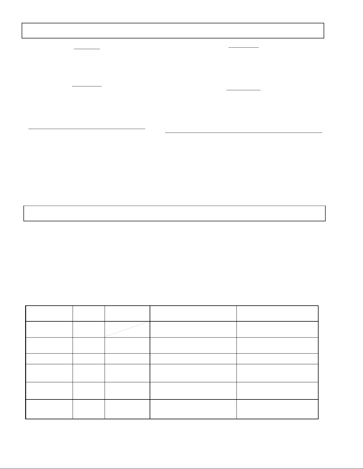
Diagnostic Item No. of times Self-diagnostic display/ Probable Cause Detected Symptoms
Description STANDBY/TIMER Diagnostic result Location
* Power does not turn on Does not light * Power cord is not plugged in. * Power does not come on.
* +B overcurrent (OCP) 2 times 2:0 or 2:1 * H.OUT (Q4018) is shorted. (D board) * Power does not come on.
(Note 1) * +B REG (Q4022) is shorted. (D board) * Load on power line is shorted.
* +B overvoltage (OVP) 3 times 3:0 or 3:1 * IC5007 is faulty. (G Board) * Has entered standby mode.
* Vertical deflection stopped 4 times 4:0 or 4:1 * +/-15V is not supplied. (G board) * Has entered standby state after horizontal raster.
* White balance failure 5 times 5:0 or 5:1 * Video OUT (IC9001-9003) is faulty. (C board) * No raster is generated.
(not balanced) * MCP (IC3005) is faulty. (B board) * CRT cathode current detection reference pulse
* LOW B OCP/OVP
(overcurrent/overvoltage) 6 times 6:0 or 6:1 *+5 line is overloaded. (B,V Boards) * No picture.
(Note 3) *+5 line is shorted. (B,V Boards)
lamp flashes
* Fuse is burned out. (F5501) * No power is suppled to the TV.
* AC power supply is faulty.
* IC9001,9002, 9003 is shorted. (C board)
* IC 7003 is faulty. (D board) * Vertical deflection pulse is stopped.
* Power line is shorted or power supply is stopped.
* G2 is improperly adjusted. (Note 2) output is small.
* IC5008 is faulty. (G Board)
Note 1: If a +B overcurrent is detected, stoppage of the vertical deflection is detected simultaneously.
The symptom that is diagnosed first by the microcontroller is displayed on the screen.
Note 2: Refer to Screen (G2) Adjustment in Section 3-4 of this manual.
Note 3: If standby lamp flashes 6 times, unplug unit and wait ten seconds before performing adjustment.
— 4 —

2. DISPLAY OF STANDBY/TIMER LIGHT FLASH COUNT
< Diagnostic items > < Flash count >
• +B overcurrent 2 times
• +B overvoltage 3 times
• Vertical deflection 4 times
stopped
• White balance failure 5 times
• Low B OCP/OVP 6 times
KW-34HD1
Lamp ON 0.3 sec.
Lamp OFF 0.3 sec.
Lamp OFF
3 sec.
STANDBY/SLEEP lamp
* One flash count is not used for self-diagnostic.
3. STOPPING THE STANDBY/TIMER FLASH
Turn off the power switch on the TV main unit or unplug the power cord from the outlet to stop the STANDBY/TIMER lamp from flashing.
4. SELF-DIAGNOSTIC SCREEN DISPLAY
For errors with symptoms such as "power sometimes shuts off" or "screen sometimes goes out" that cannot be confirmed, it is possible to bring up
past occurances of failure for confirmation on the screen:
[To Bring Up Screen Test]
In standby mode, press buttons on the remote commander sequentially in rapid succession as shown below:
Screen display
channel
5
Sound volume
–
Power ON
Note that this differs from entering the service mode (sound volume + ).
Self-Diagnostic screen display
SELF DIAGNOSTIC
2: +B OCP 0 <-------------
Numeral "0" means that no fault has been detected.
3: +B OVP 0
4: V STOP 0
5: AKB 1 <-------------
Numeral "1" means a fault has been detected one time only.
6: LOWB 0
101: WDT 0
5. HANDLING OF SELF-DIAGNOSTIC SCREEN DISPLAY
Since the diagnostic results displayed on the screen are not automatically cleared, always check the self-diagnostic screen during repairs. When
you have completed the repairs, clear the result display to "0".
Unless the result display is cleared to "0", the self-diagnostic function will not be able to detect subsequent faults after completion of the repairs.
[Clearing the result display]
To clear the result display to "0", press buttons on the remote commander sequentially as shown below when the diagnostic screen is being
displayed.
ENTER
Channel
[Quitting Self-diagnostic screen]
To quit the entire self-diagnostic screen, turn off the power switch on the remote commander or the main unit.
8
— 5 —

KW-34HD1
6. SELF-DIAGNOSTIC CIRCUIT
ST +5V
SLEEP/
STBY LED
H1
+B OCP
Low-Error
+B OVP
R5026
R5101
+135V
Q5009
+B OCP
(+B)
ST+5V
Q5016
Q5020
B
MAIN MICRO PROC.
49
O_STBYLED
44
I_OCP
43
I_LB_ERR
45
I_OVP
D5022
D5013
IC3251
G
D5019
+B OVP
IO_SDAT
IO_SCLK
O_AC RLY
1
31
28
71
IC5007
+B CONT
3
OG
I
2
D5020
Q5008
Q5504
ST+5V
Q5003
D5017
D5048
Q5502
Q5503
RY5501
ST+5V
Q5018
Q5017
+12v
D5047
D5046
DIGITAL DEFLECTION
M
CONTROL
SDA
4
5
SCL
COMPONENT VIDEO
B
55
56
BS +5V
IC5008
+5V CONT
5
IC1305
VPROT
11
IC3005
PROCESSOR
D-SCL
D-DAT
1
+5V OCP SW
IK_IN
Q5019
V.DY(-)
41
H.PROT
R5038
R5076
AKB
CRT
D5042
+5V OVP
+B overcurrent (OCP) Occurs when an overcurrent (more then 3A) on the +B(135V) line is detected by R5026 /
R5101. It will cause Q5009 to turn on and force the AC relay to turn off through Q5016
and Q5020.
+B overvoltage (OVP) Occurs when an overvoltage (more than +150V) on the +B (135V) line is detected by
D5019. The AC Relay will turn off through Q5003 and Q5008.
Vertical deflection stopped Occurs when an absence of the vertical deflection pulse is detected by IC1305. Power
supply will shut down when waveform interval exceeds 2 seconds.
White balance failure If the RGB levels* do not balance within 2 seconds after the power is turned on, this error
will be detected by IC3005. The TV will stay on, but there will be no picture.
*(Refers to the RGB levels of the AKB detection Ref pulse that detects IK.)
Low B OCP/OVP Occurs when overcurrent (more than 6.4V) on the +5V line is detected by D5042. The
AC relay is turned off through Q5017, Q5018 and signals to IC3002.
— 6 —
SAFETY CHECK-OUT
KW-34HD1
After correcting the original service problem, perform the
following safety checks before releasing the set to the
customer:
1. Check the area of your repair for unsoldered or poorlysoldered connections. Check the entire board surface
for solder splashes and bridges.
2. Check the interboard wiring to ensure that no wires
are “pinched” or contact high-wattage resistors.
3. Check that all control knobs, shields, covers, ground
straps, and mounting hardware have been replaced.
Be absolutely certain that you have replaced all the
insulators.
4. Look for unauthorized replacement parts, particularly
transistors, that were installed during a previous
repair. Point them out to the customer and
recommend their replacement.
5. Look for parts which, though functioning, show
obvious signs of deterioration. Point them out to
the customer and recommend their replacement.
6. Check the line cords for cracks and abrasion.
Recommend the replacement of any such line cord
to the customer.
7. Check the B+ and HV to see if they are specified
values. Make sure your instruments are accurate;
be suspicious of your HV meter if sets always have
low HV.
8. Check the antenna terminals, metal trim, “metallized"
knobs, screws, and all other exposed metal parts for
AC Leakage. Check leakage as described below.
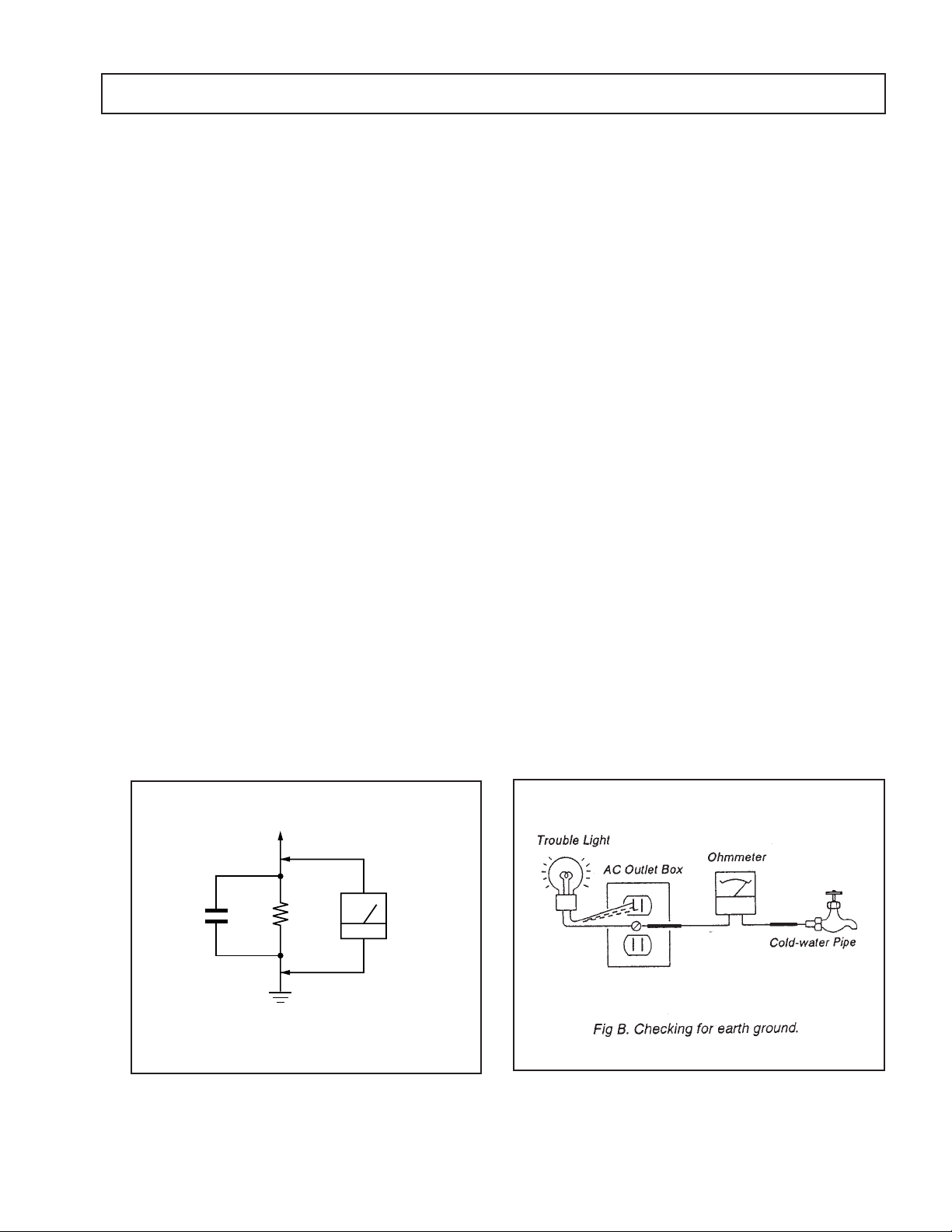
LEAKAGE TEST
The AC leakage from any exposed metal part to earth ground
and from all exposed metal parts to any exposed metal part having
a return to chassis, must not exceed 0.5 mA (500 microampere).
Leakage current can be measured by any one of three methods.
1. A commercial leakage tester, such as the Simpson 229 or
RCA WT-540A. Follow the manufacturers' instructions to
use these instructions.
2. A battery-operated AC milliammeter. The Data Precision
245 digital multimeter is suitable for this job.
3. Measuring the voltage drop across a resistor by means of
a VOM or battery-operated AC voltmeter. The "limit"
indication is 0.75 V, so analog meters must have an accurate
low voltage scale. The Simpson's 250 and Sanwa
SH-63Trd are examples of passive VOMs that are suitable.
Nearly all battery operated digital multimeters that have a
2V AC range are suitable. (See Fig. A)
HOW TO FIND A GOOD EARTH GROUND
A cold-water pipe is guaranteed earth ground; the cover-plate
retaining screw on most AC outlet boxes is also at earth gr ound.
If the retaining screw is to be used as your earth-ground, verify
that it is at ground by measuring the resistance between it and a
cold-water pipe with an ohmmeter. The r eading should be zero
ohms. If a cold-water pipe is not accessible, connect a 60-l00 watts
trouble light (not a neon lamp) between the hot side of the receptacle and the retaining screw. Try both slots, if necessary, to
locate the hot side of the line, the lamp should light at normal
brilliance if the screw is at ground potential. (See Fig. B)
To Exposed Metal
Parts on Set
AC
1.5 k
0.15 µF
Fig. A. Using an AC voltmeter to check AC leakage.
Ω
Earth Ground
Voltmeter
(0.75 V)
— 7 —
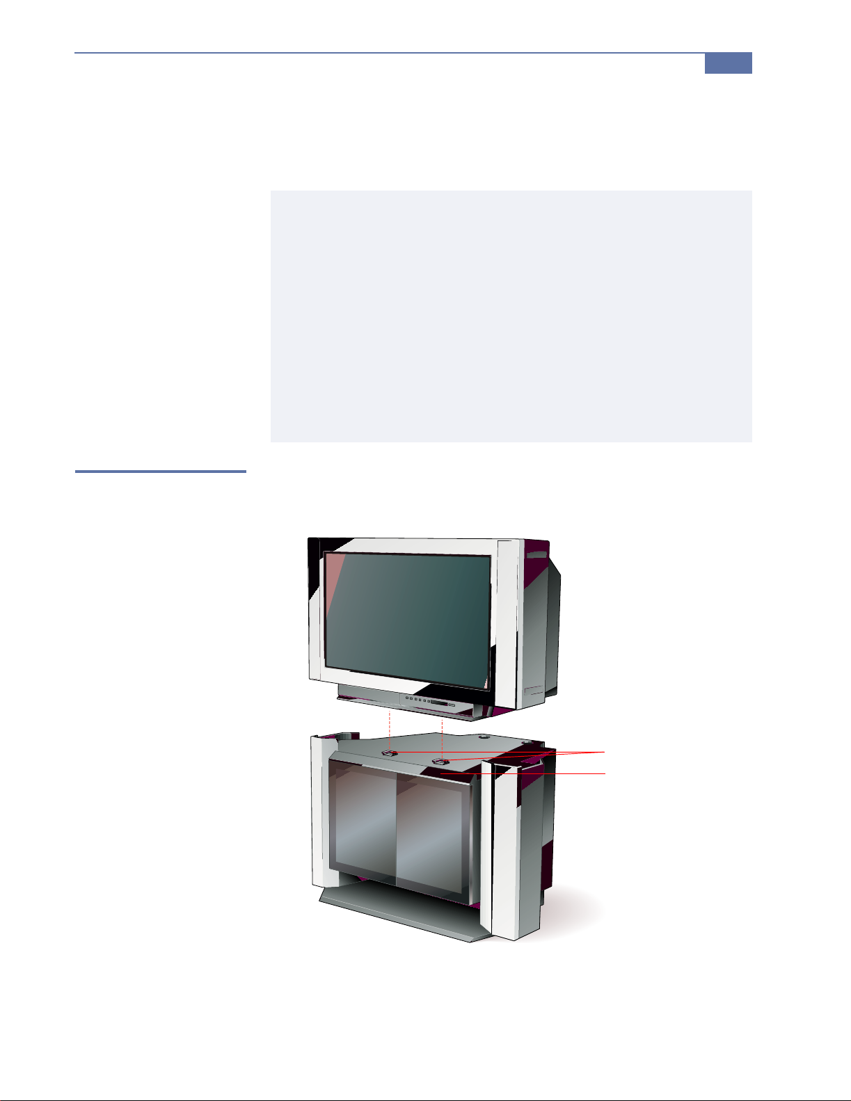
Setting Up the TV, DTV Receiver, and Stand
The DTV stand is shipped fully assembled. Follow these instructions to set up
the TV and DTV receiver.
The use of the Sony stand supplied with this DTV system is recommended
to ensure the safety, easy placement, proper operation, and optimal
performance of this product. In the event you decide not to use the stand,
Sony recommends the following guidelines:
❑ The DTV receiver must be placed underneath the TV while
maintaining a distance of 12 inches between the top of the DTV
receiver and the bottom of the TV.
❑ The cable must be properly routed as to avoid any damage.
❑ Staples or hold-down devices, which could pierce the cable, should
not be used.
❑ Proper ventilation of the TV and receiver must be provided.
❑ Other electronic components should be placed at a minimum of 12
inches to avoid any interference.
Installing the DTV System
17
Place the TV on the
Stand
1 Carefully place the TV on top of the stand so that the fe et on the TV fit into
the guides on the stand.
Guides
Foot cover
The TV should be flush against the foot cover on the stand.
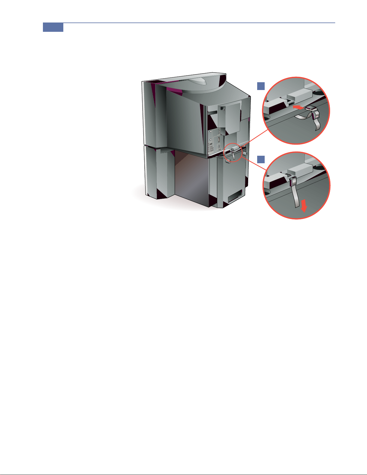
18
Installing the DTV System
2 To secure the TV to the stand, insert the buckle into the slot in the rear
cover of the TV.
2
3
3 Pull the strap down to tighten it.

Installing the DTV System
19
Connect the TV
and DTV Receiver
For details on routing the cables through the stand, see page 21.
1 Route the antenna through the stan d to the lower shelf and connect it to
the DTV receiver’s FROM ANTENNA jack.
You cannot receive digital channels unless you connect a terrestrial antenna . Th is
b
applies even if you normally receive your programming through cable or satellite.
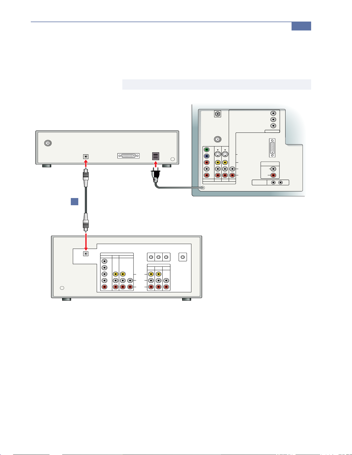
2 Connect the digital I/O cable to the DTV receiver’s I/O jack.
✍ Before connecting the I/O cable, check that it is oriented as shown — with the noise filter
closer to the DTV receiver.
3 Route the other end of the digital I/O cable through the stand and co nnect
it to the TV’s DTV I/O jack.
4 Route the TV’s AC power cord through the stand and connect it to the
receiver’s AC outlet.
5 Route the receiver’s AC power cord through the stand. Connect this to an
AC wall outlet only after you have finished connecting all components.

20
Installing the DTV System
FROM
ANTENNA
CABLE
VHF/UHF
Y
B
P
PR
L
R
DVD 1 3 HD
VIDEO IN
AC Cord
DOLBY DIGITAL
OUTPUT
(OPTICAL)
FOR USE WITH
HD (1080i)
INPUT ONLY
DTV I/O
FOR USE WITH
KW-34HD1
(DTV RCEIVER)
S VIDEO
VIDEO
(MONO)
ONLY
AUDIO OUT
L
R
(MONO)
AUDIOAUDIO
CONTROL S
L
R
DTV RECEIVER
Y
B
P
PR
HD
(VAR/FIX)
IN OUT
3
4
I/O Cable
Antenna
5
21
Noise Filter

Installing the DTV System
21
Route the Cables
through the Stand
The numbers on the following illustration correspond with the steps described
in “Connect the TV and DTV Receiver” on page 19.
3
4
2
5
1

Installing the DTV System
23
Secure the DTV
Receiver
Place the DTV receiver on the bottom shelf of the stand, so that its feet are
secured by the guides on the shelf. After you finish connecting the receiver,
snap the cover to the bottom shelf into position, and then pull the door down
to conceal the front panel of the receiver.
Using the stand’s sliding doors
The stand has two glass doors that slide outward as shown.
About the stand bumpers
The back of the stand includes two rubber bumpers that guard against
crimping damage to the I/O cable, which could result from placing the stand
too close to the wall. To avoid potential damage to the cable, do not remove
these bumpers.
24
Installing the DTV System
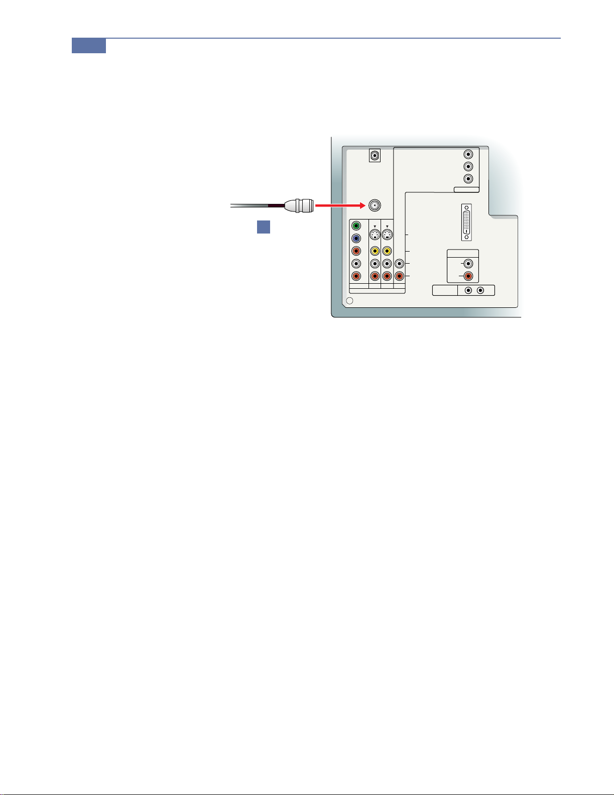
Connecting a VHF/UHF Antenna
1 Connect the VHF/UHF antenna to the TV ’s VHF/UHF jack.
DTV I/O
FOR USE WITH
KW-34HD1
(DTV RCEIVER)
ONLY
(MONO)
AUDIOAUDIO
CONTROL S
Y
B
P
PR
HD
AUDIO OUT
(VAR/FIX)
L
R
IN OUT
FOR USE WITH
S VIDEO
VIDEO
L
(MONO)
R
HD (1080i)
INPUT ONLY
CABLE
VHF/UHF
1
Y
B
P
PR
L
R
DVD 1 3 HD
VIDEO IN
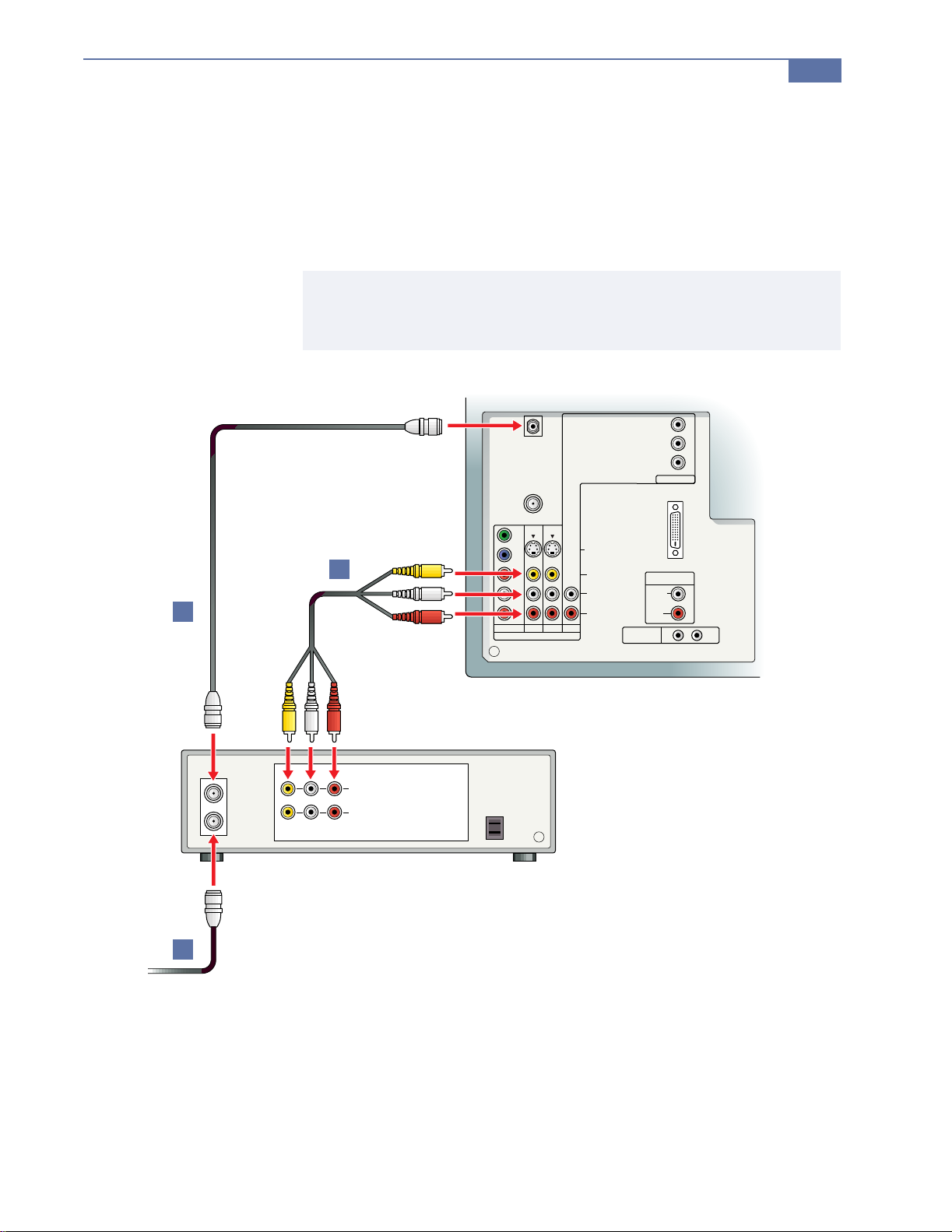
Connecting a VCR and Cable
1 Connect the cable TV cable to the VCR’s IN jack.
2 Using a coaxial cable, connect the VCR’s OUT jack to the TV’s CABLE jack.
3 Using an A/V cable, connect the VCR’s A/V OUT jacks to the TV’s A/V
IN jacks.
✍ If Your VCR Has an S VIDEO JACK: For improved picture quality, use an S VIDEO connection instead
of the yellow video cable on your combined A/V cable. Using an S VIDEO cable, connect the VCR’s
S VIDEO OUT jack to the TV’s S VIDEO IN jack. S VIDEO does not provide audio, so audio cables
must still be connected to provide sound.
Installing the DTV System
25
DTV I/O
FOR USE WITH
KW-34HD1
(DTV RCEIVER)
ONLY
AUDIO OUT
(MONO)
AUDIOAUDIO
CONTROL S
Y
B
P
PR
HD
(VAR/FIX)
L
R
IN OUT
FOR USE WITH
S VIDEO
VIDEO
L
(MONO)
R
HD (1080i)
INPUT ONLY
CABLE
VHF/UHF
Y
B
3
2
P
PR
L
R
DVD 1 3 HD
VIDEO IN
VCR
AUDIO
LINE OUT
LINE IN
RL
OUT
IN
VIDEO
1
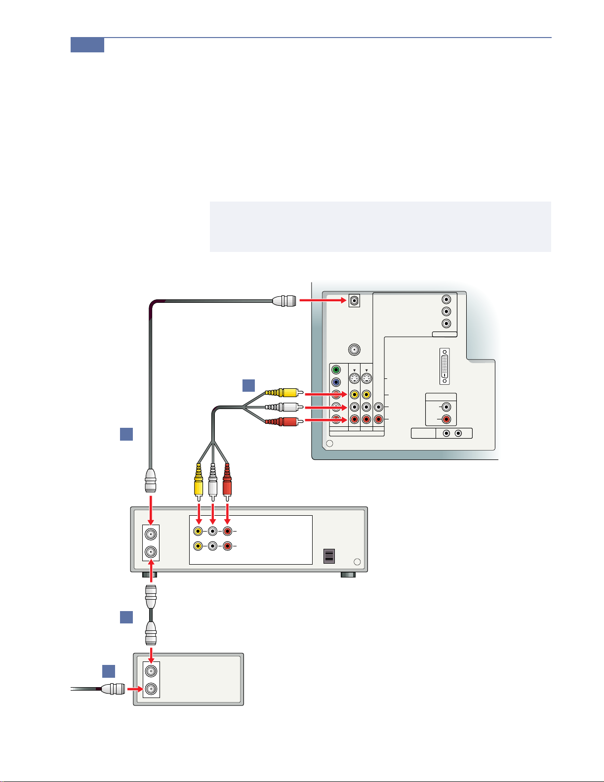
26
Installing the DTV System
Connecting a VCR and Cable Box
1 Connect the cable TV antenna to the cable box’s IN jack.
2 Using a coaxial cable, connect the cable box’s OUT jack to the VCR’s IN
jack.
3 Using a coaxial cable, connect the VCR’s OUT jack to the TV’s CABLE jack.
4 Using an A/V cable, connect the VCR’s A/V OUT jacks to the TV’s A/V
IN jacks.
✍ If Your VCR Has an S VIDEO JACK: For improved picture quality, use an S VIDEO connection instead
of the yellow video cable on your combined A/V cable. Using an S VIDEO cable, connect the VCR’s
S VIDEO OUT jack to the TV’s S VIDEO IN jack. S VIDEO does not provide audio, so audio cables
must still be connected to provide sound.
DTV I/O
FOR USE WITH
KW-34HD1
(DTV RCEIVER)
ONLY
(MONO)
AUDIOAUDIO
CONTROL S
Y
B
P
PR
HD
AUDIO OUT
(VAR/FIX)
L
R
IN OUT
FOR USE WITH
S VIDEO
VIDEO
L
(MONO)
R
HD (1080i)
INPUT ONLY
CABLE
VHF/UHF
Y
B
4
3
P
PR
L
R
DVD 1 3 HD
VIDEO IN
VCR
AUDIO
LINE OUT
LINE IN
RL
OUT
IN
VIDEO
2
CABLE BOX
1
OUT
IN

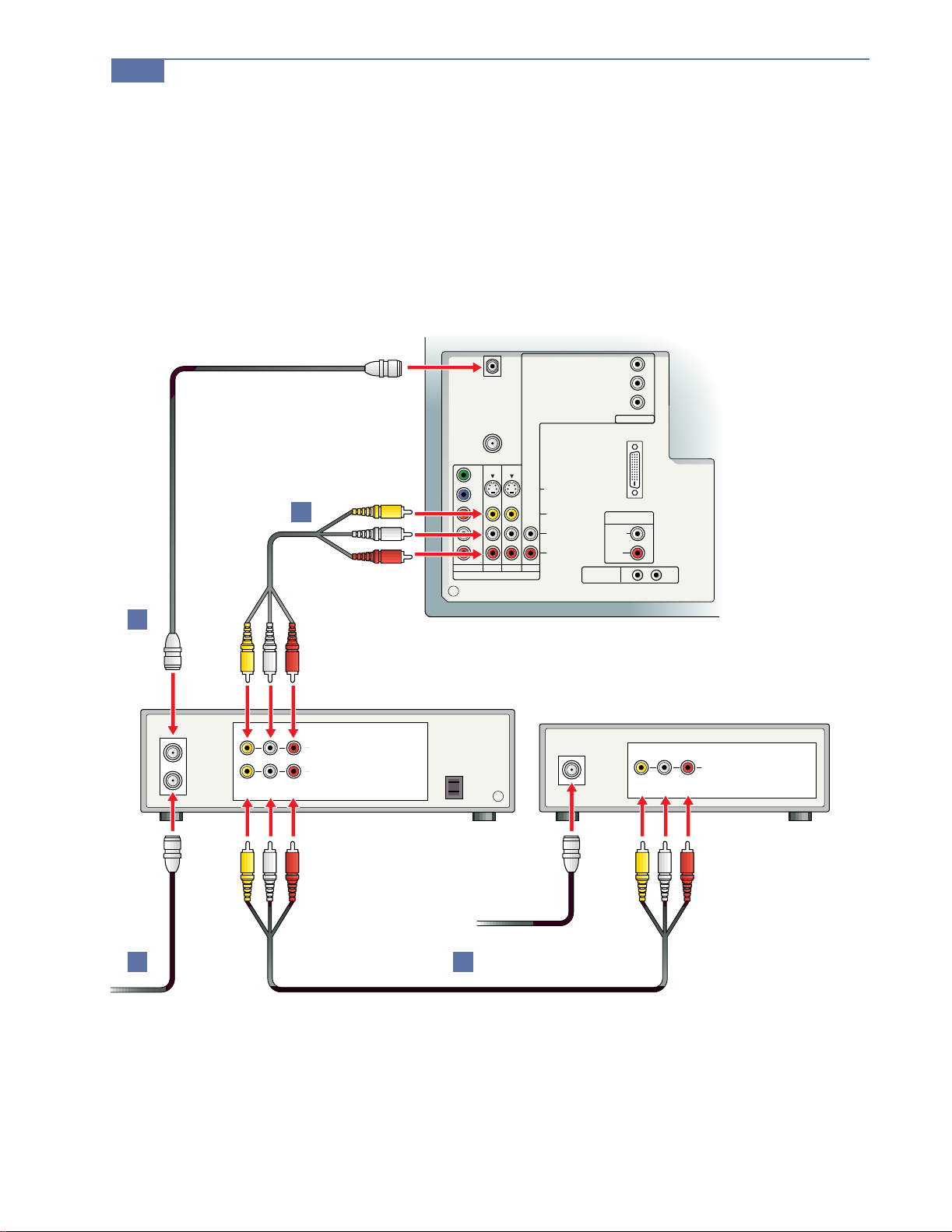
Connecting a DBS (Satellite) Receiver
1 Connect the satellite antenna cable to the DBS receiver’s SATELLITE IN
jack.
2 Using an A/V cable, connect the DBS receiver’s A/V OUT jacks to the
TV’s A/V IN jacks.
✍ If Your DBS Receiver Has an S VIDEO JACK: For improved picture quality, use an S VIDEO connection
instead of the yellow video ca bl e on yo ur co mbin ed A/ V cabl e. Using an S VIDEO cable, connect the
DBS receiver’s VIDEO OUT jack to the TV’s S VIDEO IN jack. S VIDEO does not provide audio, so
audio cables must still be connected to provide sound.
Installing the DTV System
27
DBS RECEIVER
SATELLITE IN
R L
AUDIO
DTV I/O
FOR USE WITH
KW-34HD1
(DTV RCEIVER)
ONLY
(MONO)
AUDIOAUDIO
CONTROL S
Y
B
P
PR
HD
AUDIO OUT
(VAR/FIX)
L
R
IN OUT
FOR USE WITH
S VIDEO
VIDEO
L
(MONO)
R
HD (1080i)
INPUT ONLY
CABLE
VHF/UHF
Y
B
P
2
LINE OUT
VIDEO
PR
L
R
DVD 1 3 HD
VIDEO IN
1
28
Installing the DTV System
Connecting a DBS (Satellite) Receiver with a VCR
1 Connect the cable TV cable to the VCR’s IN jack.
2 Using a coaxial cable, connect the VCR’s OUT jack to the TV’s CABLE jack.
3 Using an A/V cable, connect the DBS receiver’s A/V OUT jacks to the
VCR’s A/V IN jacks.
4 Using an A/V cable, connect the VCR’s A/V OUT jacks to the TV’s A/V
IN jacks.
2
VCR
OUT
DTV I/O
FOR USE WITH
KW-34HD1
(DTV RCEIVER)
ONLY
AUDIOAUDIO
CONTROL S
Y
B
P
PR
HD
AUDIO OUT
(VAR/FIX)
L
(MONO)
R
IN OUT
FOR USE WITH
S VIDEO
VIDEO
L
(MONO)
R
HD (1080i)
INPUT ONLY
CABLE
VHF/UHF
Y
B
P
4
PR
L
R
DVD 1 3 HD
VIDEO IN
DBS RECEIVER
LINE OUT
IN
R L
AUDIO
LINE IN
VIDEO
SATELLITE IN
R L
AUDIO
LINE OUT
VIDEO
1
3
Connecting an A/V Receiver with Digital Audio IN
1 Using an optical cable (not supplied), connect the DTV receiver’s Dolby
Digital Output (Optical) jack to the A /V receiver’s Digital Signal IN jack.
✍ A/V receiver’s Digital Signal IN jacks are sometimes labeled AC-3 or PCN.
Installing the DTV System
29
FROM
ANTENNA
AC-3
OPTICAL OUT
1
DIGITAL SIGNAL
DTV RECEIVER
A/V RECEIVER
VIDEO IN
DVD 1 3 4
Y
P
B
P
R
L
R
VIDEO
(MONO)
AUDIO
R
L
S-LINK CONTROL S
OUT IN
OUT
AUDIO
MONITOR
TV
(VAR/FIX)
CABLE
VHF/UHF
Y
B
P
P
R
L
R
DVD 1 3 HD
VIDEO IN
FOR USE WITH
INPUT ONLY
S VIDEO
VIDEO
L
(MONO)
R
HD (1080i)
CONTROL S
DTV I/O
FOR USE WITH
KW-34HD1
(DTV RCEIVER)
ONLY
Y
B
P
P
R
HD
AUDIO OUT
(VAR/FIX)
L
(MONO)
AUDIOAUDIO
R
IN OUT

30
Installing the DTV System
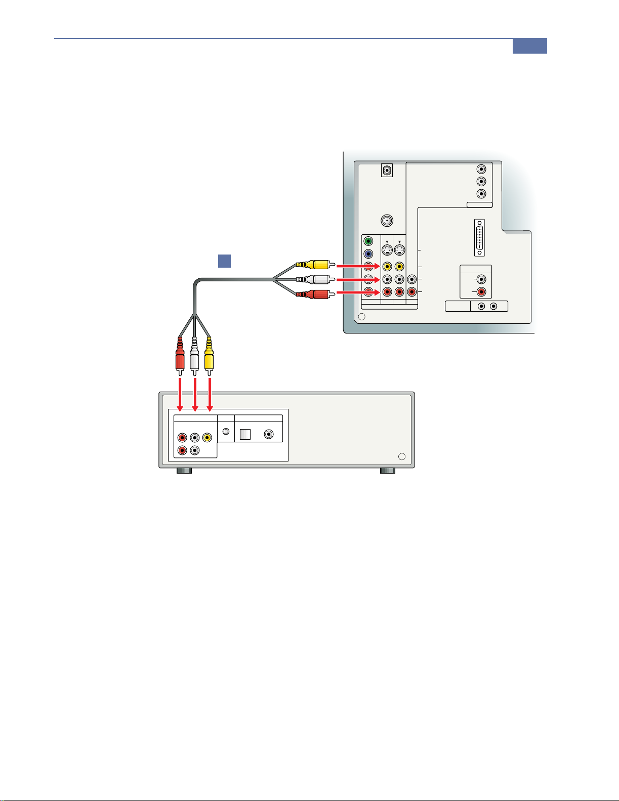
Connecting an Audio Receiver
1 Using audio cables, connect the TV’s AUDIO OUT jacks to the audio
receiver’s audio IN jacks.
CABLE
VHF/UHF
Y
B
P
PR
L
R
DVD 1 3 HD
VIDEO IN
DTV I/O
FOR USE WITH
KW-34HD1
(DTV RCEIVER)
ONLY
(MONO)
AUDIOAUDIO
CONTROL S
Y
B
P
PR
AUDIO OUT
(VAR/FIX)
L
R
IN OUT
FOR USE WITH
HD (1080i)
INPUT ONLY
S VIDEO
VIDEO
L
(MONO)
R
AUDIO RECEIVER
HD
1
R L
AUDIO
LINE IN
LINE OUT
Connecting a DVD Player with A/V Connectors
1 Using A/V cables, connect the DVD player’s A/V OUT jacks to the TV’s
A/V IN jacks.
Installing the DTV System
31
LINE OUT
R
(MONO)
DTV I/O
FOR USE WITH
KW-34HD1
(DTV RCEIVER)
ONLY
AUDIOAUDIO
CONTROL S
Y
B
P
PR
HD
AUDIO OUT
(VAR/FIX)
L
(MONO)
R
IN OUT
FOR USE WITH
S VIDEO
VIDEO
L
(MONO)
R
HD (1080i)
INPUT ONLY
CABLE
VHF/UHF
Y
B
1
P
PR
L
R
DVD 1 3 HD
VIDEO IN
DVD PLAYER
S-LINK
DIGITAL OUT
VIDEO
L
OPTICAL COAXIAL

34
Installing the DTV System
Using the Control S Feature
CONTROL S allows you to control your DTV system and other Sony
equipment with one remote control.
T o control your other Sony equipment with your DTV’s remote con trol, use the
CONTROL S cable to connect the equipment’s CONTROL S IN jack to the
TV’s CONTROL S OUT jack.
CABLE
VHF/UHF
Y
B
P
PR
L
R
DVD 1 3 HD
VIDEO IN
FOR USE WITH
HD (1080i)
INPUT ONLY
S VIDEO
VIDEO
L
(MONO)
R
DTV I/O
FOR USE WITH
KW-34HD1
(DTV RCEIVER)
ONLY
AUDIOAUDIO
CONTROL S
Y
B
P
PR
HD
AUDIO OUT
(VAR/FIX)
L
(MONO)
R
IN OUT
OUT
LINE OUT
IN
VIDEO
AUDIO
LINE IN
RL
CONTROL S
IN

TV Controls and Connectors
TV Front Panel
VIDEO 2 IN
Other Information
S VIDEO
VIDEO L-AUDIO-R
51
S VIDEO
VIDEO 2 IN
VIDEO L-AUDIO-R
Connection Description
SETUP
Displays the Auto Setup screen, which enables you to run Auto Program. Auto Program
automatically programs the TV to receive channels for each input source, including cabl e,
VHF/UHF, and digital.
VIDEO 2 IN
Useful for connecting A/V components that will not be connected permanently, such as a
camcorder.
SVIDEO: Connects to the S VIDEO OUT jack of your S VIDEO equipped component.
VIDEO and AUDIO (L/R): Connects to the audio and video OUT jacks on VCR or other video
component.
TV/VIDEO
VOLUME -/+
CHANNEL -/+
STEREO
POWER
Press repeatedly to step through available video inputs:
TV, VIDEO 1, VIDEO 2, VIDEO 3, DVD, HD.
Press to adjust the volume (+ up or - down).
Press to scan through the channels (+ up or - down).
Indicates the current program is broadcast in stereo.
Turns the DTV system on and off. If a video input indication (e.g., VIDEO 1, VIDEO 2)
appears, press TV/VIDEO until a channel number appears.
SET UP TV/VIDEO VOLUME CHANNEL POWER
STEREO STAND BY
52
Other Information
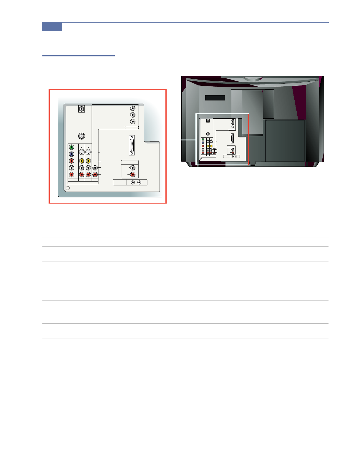
TV Rear Panel
DTV I/O
FOR USE WITH
KW-34HD1
(DTV RCEIVER)
ONLY
AUDIOAUDIO
CONTROL S
Y
B
P
P
R
HD
AUDIO OUT
(VAR/FIX)
L
(MONO)
R
IN OUT
CABLE
VHF/UHF
Y
B
P
P
R
L
R
DVD 1 3 HD
VIDEO IN
FOR USE WITH
INPUT ONLY
S VIDEO
VIDEO
L
(MONO)
R
HD (1080i)
Connection Description
CABLE
VHF/UHF
DVD
S-VIDEO (2)
Connects to your cable.
Connects to your VHF/UHF antenna.
Connects to your DVD player’s component video (Y, PB, PR) and audio (L, R) jacks.
Connects to the S VIDEO OUT jack of your VCR or other Sony S VIDEO equipped video
component.
AUDIO
(L/R)/VIDEO (2)
HD/HD 1080i
DTV I/O
Connects to the audio and video OUT jacks on your VCR or other video component. A
third video input (VIDEO2) is located on the front panel of the TV.
Connects to di gital cable boxes (as they become availab le in the future).
Connects to the DTV receiver
(model KW-34HD1 only)
AUDIO OUT (VARIABLE)
Connects to the right and left audio inputs of your audio or video component.
L (MONO)
R
CONTROL-S IN/OUT
Allows the TV to receive (IN) and send (OUT) r emote co ntr ol signa ls to other Sony infrar edcontrolled audio or video components.
CABLE
VHF/UHF
Y
B
P
P
R
L
R
DVD 1 3 HD
VIDEO IN
S VIDEO
VIDEO
(MONO)
FOR USE WITH
HD (1080i)
INPUT ONLY
L
R
DTV I/O
FOR USE WITH
KW-34HD1
(DTV RCEIVER)
CONTROL S
ONLY
Y
P
P
R
AUDIO OUT
(VAR/FIX)
L
(MONO)
AUDIOAUDIO
R
IN OUT
B
HD
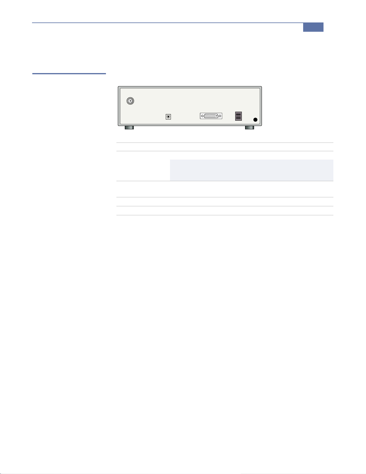
Receiver Controls and Connectors
Receiver Rear Panel
FROM
ANTENNA
Connection Description
FROM ANTENNA
DOLBY DIGITAL
OUTPUT (OPTICAL)
DTV I/O
AC In
Other Information
AC-3
OPTICAL OUT
Connects to your terrestrial antenna.
b You cannot r eceive digital channels unless you connect a terre strial
antenna. This appli es even if you normally recei v e your
programming through cable or satellite.
Allows you to connect your DTV receiver to a digital audio
component.
Connects to the TV’s DTV I/O jack (model KW-34HD1 only)
Connects to the TV’s AC plug.
53
54
Other Information
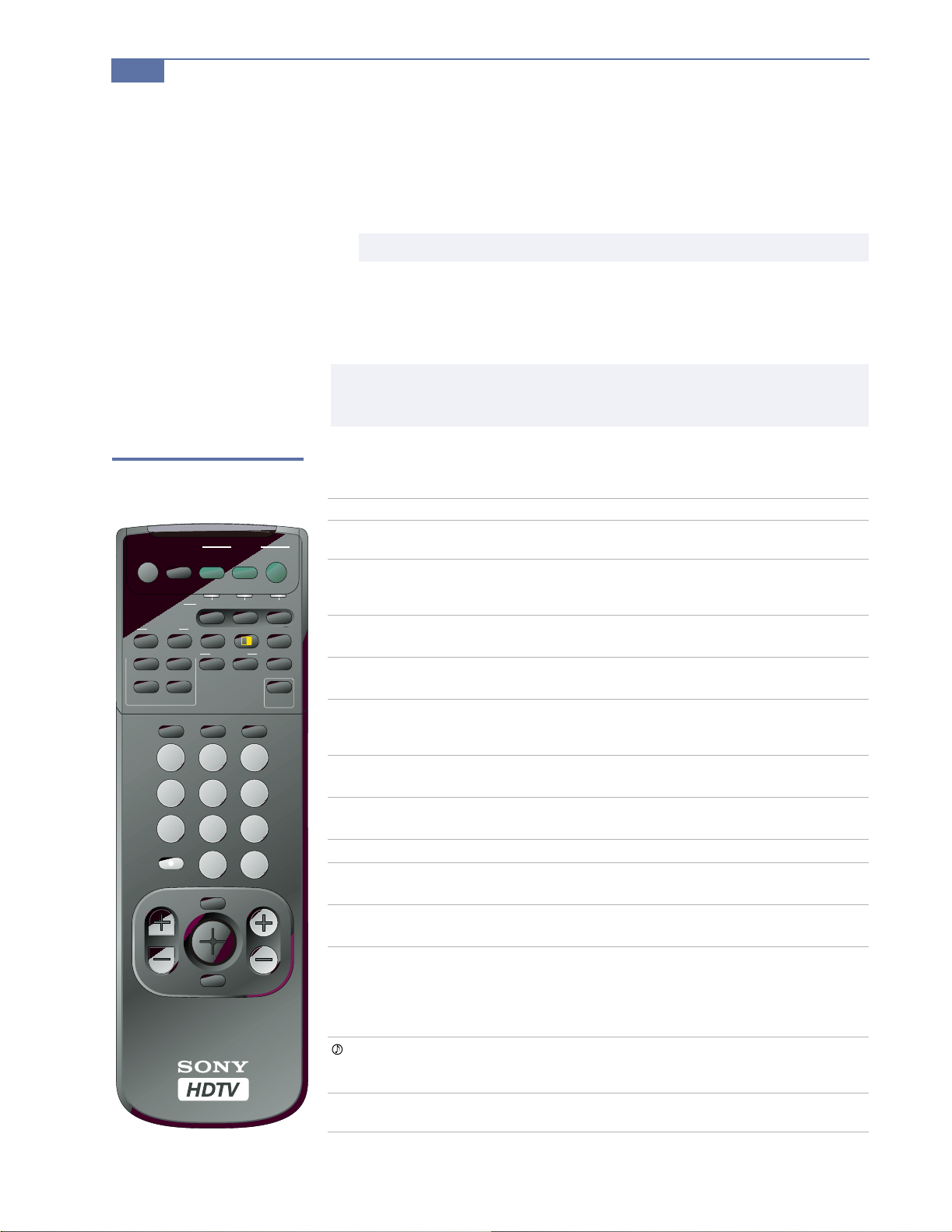
Using the Remote Control
1 Select the equipment that you want to using the corresponding
FUNCTION button (or open the lid on the remote control and set the slide
switch to the position that you set for the equipment).
2 Aim the remote control at the equipment.
3 Press the POWER button of the equipment to turn it on and off.
To control other functions of the equipment, see the table that follows.
✍ Buttons described in the following table can operate video equipment other than the DTV system
only if you program med the rem ote c ontr ol and t he eq uipm ent sup port s t he func tion d esc ribed. See
page 57 for instructions on programming the remote control.
Outside Panel
Button Description
MUTING
SLEEP
DVD/VTR
(POWER)
DBS/CABLE
(POWER)
TV
(POWER)
DVD/VTR
(FUNCTION)
DBS/CABLE
(FUNCTION)
TV (FUNCTION)
LEFT
(ZOOM UP)
RIGHT
(ZOOM UP)
FREEZE
RESET
MUTING
FUNCTION
ZOOM UP
LEFT
WIDE ZOOM V CENTER
NORMAL ZOOM
FULL CAPTION
SLEEP
RIGHT
DVD/
VTR
FREEZE
VIDEO AUDIO
TV/VIDEOJUMP
0
VOL CH
MENU
GUIDE
POWER
DBS
TV
CABLE
TV
DBS/CABLEDVD/VTR
ANT
RESET
TV/DBS
PICTURE
MODE
ALTERNATE DISPLAY
321
654
987
ENTER
RM-Y158
✍ The FUNCTION buttons flash to indicate wh ich compon ent th e remote cont rol is set to oper a te .
Press to mute the sound. Press again or press
the sound.
Press repeatedly until the TV displays the time in minutes (30,
60, or 90) that you want the T V to r emain on befor e shutting of f
automatically. Cancel by pressing until SLEEP OFF appears.
Turns the DVD player, MDP player, or VTR (VCR) on and off.
Turns the DBS receiver or cable box on and off.
Turns the DTV system on and off. If a video input indication
(e.g., VIDEO 1, VIDEO 2) appears, press TV/VIDEO until a
channel number appears.
Activates the remote control for use with a DVD player, MDP
player, or VTR (VCR).
Activates the remote control for use with a DBS receiver or
cable box.
Activates the remote control for use with the DTV.
Enlarges the left picture when the DTV is in P&P mode. For
details, see “Using the Freeze Function” on page 40.
Enlarges the right picture when the DTV is in P&P mode. For
details, see “Using the Freeze Function” on page 40.
Switches to Picture and Picture mode, displaying the “frozen”
picture frame (when FREEZE was pressed) on the left and the
current program on the righ t. Useful for capturing information,
such as phone numbers, recipes, etc. Press again to cancel. For
details, see “Using the Freeze Function” on page 40.
Switches to Picture an d P ict ure mode, displaying left and rig ht
pictures. Press again to cancel. For details, see “Using Picture
and Picture (Twin Picture) Mode” on page 39.
Resets the DT V to th e fa ctor y de fault se tting s for the Video and
Audio menus. For details, see pages 43 to 45.
VOL +
to restore
Button Description
WIDE ZOOM
V CENTER
NORMAL/FULL
ZOOM/CAPTION
VIDEO (ALTERNATE)
(for digital
broadcasts only)
AUDIO (ALTERNATE)
(for digital
broadcasts only)
DISPLAY
PICTURE MODE
JUMP
TV/VIDEO
ANT
0 – 9 and ENTER
MENU
VOL +/CH +/GUIDE
Enlarges 4:3 pictures. The upper and lower parts of the pictur e
are stretched to fill the 16:9 screen. Also available in the Wide
Screen mode menu. For details , see “Using Wide Screen Mode”
on page 38.
Allows you to move the picture away from the top of the
screen in Wide Zoom, Zoom, and Caption modes. (Not
available for Full or Normal mode pictures). Also available in
the Wide Screen mode menu. For details, see “Using Wide
Screen Mode” on page 38.
Enlarges 4:3 pict ur es. Th e pictur e is str etc hed hor izontally onl y
to fill the 16:9 screen. Also available in the Wide Screen menu.
For details, see “Using Wide Screen Mode” on page 38.
Enlarges the original film dimensions to fill the 16:9 screen.
Also available in the W i de Scre en menu. For deta ils, see “Using
Wide Screen Mode” on page 38.
Toggles through the available video displays for the current
program. (For example, a sporting event that broadcasts
multiple camera angles.)
Toggles through the available audio tracks for the current
program. (For example, a sporting event that broadcasts
multiple commentators.)
Press re pe a tedly to step through availa ble displays.
Caption V ision and XDS (Extended Data Services) are
displayed if the broadcaster offers this service (see page 48).
Cancel by pressing until DISPLAY OFF appears.
Press repeatedly to step through the available video modes:
Vivid, Standard, Movie, Sports. Also available in the Video
menu. For details, see “Selecting Video Options” on page 43.
Press to jump back and forth between two channels. The DTV
alternates between the current channel and the las t channel
that was selected using the 0-9 buttons.
Press repeatedly to step through availa ble video inputs:
TV, VIDEO 1, VIDEO 2, VIDEO 3, DVD, HD.
Press repeatedly to select VHF/UHF (digital), and cable
inputs.
Use for direct channel selection. Press 0 – 9 to select a channel
(for example, to select channel 10, press
channel changes after 2 seconds, or you can press
immediate selection.
Use with
example, 2.1). For detai ls on selec ting sub channel s, see page 37.
Press to display the DTV menu. For details, see “Using the
DTV Menus” on page 41.
Press to adjust the volume (+ up or - down).
Press to scan through the channels (+ up or -down).
Press to display the Guide. For details, see “Using the Guide to
Select Subchannels” on page 37.
0 – 9 and ENTER buttons to select subchannels (for
Other Information
1 and 0), the
55
ENTER for
56
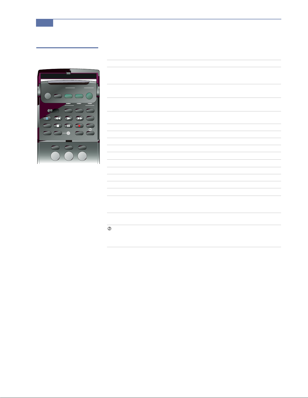
Other Information
Inside Panel
MUTING
VTR1 2 3 DVD/MDP
TV/VTR REC TITLE
CODE SET LEARN
SLEEP
DVD/
VTR
POWER
DBS
CABLE
FUNCTION
DBS/CABLEDVD/VTR
ANTTV/VIDEOJUMP
321
TV
TV
DVD MENU
Button Description
VTR1/2/3/DVD/MDP
Switches to VCR or laserdisc mode, depend ing on how
you set up the re mote con tr ol for these sw itch posit ions
(see page 57).
DVD/VTR
(FUNCTION)
DBS/CABLE
(FUNCTION)
TV (FUNCTION)
Activates t he r emo te c on tr ol for use wi th a DV D pla yer,
MDP player, or VTR (VCR).
Activates the remote control for use with a DBS receiver
or cable box.
Activates the remote control for use with the DTV
system.
Z Eject (used only with Sony brand equipment)
m Rewind
N Play
M Fast-forward
DVD MENU
TV/VTR
Displays the DVD menu.
Changes the VHF/UHF output of the VCR.
x Stop
X Pause
z Record (two buttons)
TITLE
CODE SET
Displays the DVD’s Title menu.
Used for programming the remote control to operate
non-Sony video equipment. For details, see
“Programming the Remote Control” on page 57.
LEARN
Used for setting up the remote control to operate
equipment not listed on page 58.
Provides quick access to Dolby Digital, a virtual
surround effect for Dolby-surr ound encoded pr ograms.
For details and other available effects, see “Selecting
Audio Options” on page 45.

Other Information
57
Programming the
Remote Control
The remote control is preset at the factory to operate Sony brand video
equipment.
Sony
Equipment
Beta, ED Beta VCRs VTR1 303
8 mm VCR VTR2 302
VHS VCR VTR3 301
DVD Player DVD/MDP 751
If you have video equipment other than Sony brand that you want to control
with the DTV’s remote control, use the following procedures to program the
remote control.
The equipment must have infrared (IR) remote capability in order to be used with the remote control.
✍
Switch Position on
Remote Control
Programmable
Code Number
1 Turn to “Programmable Codes” on page 58, and find the three-digit code
number for your equipment. If more than one code number is listed, use
the number listed first to complete the following procedures.
You must perform step 3 within 10 seconds of step 2, or you must start again from step 2.
✍
2 Press CODE SET.
3 Enter the three-digit code number.
4 Press ENTER.
To Check if the Code Nu mber Works
Use the following procedure to make sure the code you’ve entered works:
1 Aim the DTV’s remote control at the equipment and press the POWER
button that corresponds to that equipment.
2 If the equipment responds, you’re done. If the code doesn’t work for your
equipment:
❑ Try programming the remote control using the other codes listed for
your equipment.
❑ If you cannot get your equipment to respond to the DTV’s remote
control — even after trying all the code numbers for your equipment
— your equipment may not be compat ible with the DTV’s remote
control. If this happens, you must use your equipment ’s own remote
control to operate it. Try using the Learn feature to program specific
buttons. See “Operating a DBS (Satellite) Receiver” on page 60.
Tips
❑ If more than one code number is listed, try entering them one by one until
you come to the correct code for your equipment.
❑ If you enter a new code number, the code number you previously entered
at that setting is erased.
❑ In some rare cases, you may not be able to operate your equipment with
the supplied remote control. In this case, use the equipment’s own remote
control unit.
❑ Whenever you remove the batteries to replace them, for example if too
much time is taken, the code numbers may revert to the factory setting
and must be reset.
58
Other Information
Programmable Codes
VCR Codes
Sony VHS 301 Mitsubishi 323, 324, 325, 326
Sony 8mm 302 NEC 336, 337
Sony Beta 303 Panasonic 306, 307
Bell & Howell 343 Phillips 310
Daewoo 341 RCA 305
Emerson 316, 317, 318, 319, 320 Samsung 313, 321, 322
Fisher 330, 333, 334, 335 Scott 312
GE 304, 329 Sharp 327, 328
Go Video 339, 340 Shintom 315
Gold Star 332 Symphony 338
Hitachi 304, 305 Teknica 338, 342
JVC 314 Toshiba 311
Magnavox 308, 309, 31 0 Zenith 331
Cable Box Codes
Gemini 233 Panasonic 219, 220, 221
GI 218 Phillips 236, 237, 238, 239,
240, 241
Hamlin 223, 224, 225, 226 Samsung 235
Jerrold 201, 202, 203, 204,
205, 206, 207, 208, 222
Macom 230, 231, 232 Zenith 212, 213
Magnavox 234 Pioneer 21 4, 215
Oak 227, 228, 229 Tocom 216, 217
Scientific Atlanta 209, 210, 211
MDP Codes
Sony 701 Sanyo 706
Kenwood 707 Sharp 705
Mitsubishi 702 Yamaha 703
Panasonic 704
DVD Codes
Sony 751 RCA 755
Panasonic 753 Toshiba 754
Pioneer 752
DBS (Satellite) Codes
Sony 801
RCA 802