

Sony KV-XS29N90, KV-XS29N93 Service manual
SERVICE MANUAL
BG-3S
CHASSIS
MODEL COMMANDER DEST. CHASSIS NO.
KV-XS29N90 RM-914 TAIWAN SCC-P13J-A KV-XS29N93 RM-914 TAIWAN SCC-P13H-A
MODEL COMMANDER DEST. CHASSIS NO.
TRINITRON
®
COLOR TV
KV-XS29N90/XS29N93
RM-914
Power requirements 110 V AC, 60 Hz
Power consumption (W) Indicated on the rear of the TV
Television system M
Color system PAL*, PAL 60*, SECAM*, NTSC4.43*, NTSC3.58 * AV IN ONLY
Channel coverage
M VHF: 2 to 13 / UHF: 14 to 69 /
˘ (Antenna) 75-ohm external terminal
Audio output 8W + 8W KV-XS29N90
Number of terminal
(Video) Input: 3 Output: 1 Phono jacks; 1 VP-P, 75 ohms KV-XS29N90
(Audio) Input: 3 Output: 1 Phono jacks; 500 mVrms KV-XS29N90
(S Video) Input: 2 Y : 1 Vp-p, 75 ohms,
(Component Video) Input: 1 Phono jacks; KV-XS29N93
2 (Headphone) Output: 1 Minijack
Picture tube 29 inch
Tube size (mm) 724 Measured diagonally
Screen size (mm) 679 Measured diagonally
Dimensions (w/h/d, mm) 794 × 573 × 517 KV-XS29N90
Mass (kg) 51 KV-XS29N90
SPECIFICATIONS
CATV: 1 to 125
6W + 6W+ 15W KV-XS29N93
Input: 4 Output: 1 Phono jacks; 1 VP-P, 75 ohms KV-XS29N93
Input: 4 Output: 1 Phono jacks; 500 mVrms KV-XS29N93
unbalanced, sync negative
C : 0.286 Vp-p, 75 ohms
Y : 1 Vp-p, 75 ohms,
sync negative
B :0.7 Vp-p, 75 ohms
C
C
R :0.7 Vp-p, 75 ohms
Audio: 500 mVrms
794 × 589 × 517 KV-XS29N93
54 KV-XS29N93
Design and specifications are subject to change without notice.
Note
CAUTION
SHORT CIRCUIT THE ANODE OF THE PICTURE TUBE AND
THE ANODE CAP TO THE METAL CHASSIS, CRT SHIELD, OR
CARBON PAINTED ON THE CRT, AFTER REMOVING THE
ANODE.
SAFETY-RELATED COMPONENT WARNING!!
COMPONENTS IDENTIFIED BY SHADING AND MARK ! ON
THE SCHEMA TIC DIA GRAMS, EXPLODED VIEWS AND IN THE
PARTS LIST ARE CRITICAL TO SAFE OPERATION. REPLACE
THESE COMPONENTS WITH SONY PARTS WHOSE PART
NUMBERS APPEAR AS SHOWN IN THIS MANUAL OR IN
SUPPLEMENTS PUBLISHED BY SONY.
– 2 –

TABLE OF CONTENTS
KV-XS29N90/XS29N93
RM-914
Section Title Page
SELF DIAGNOSIS FUNCTION................................ 4
1. GENERAL........................................................................ 8
2. DISASSEMBLY
2-1. 3D Speaker Box Removal ....................................... 24
2-2. Rear Cover Removal................................................ 24
2-3. Speaker Removal ..................................................... 24
2-4. Chassis Assy Removal ............................................. 24
2-5. F Bracket Removal .................................................. 25
2-6. Service Position ....................................................... 25
2-7. Replacement of Parts ............................................... 25
2-7-1. Replacement of Control Button ..................................... 25
2-7-2. Replacement of Light Guide .......................................... 25
2-8. D3 Board Removal .................................................. 26
2-9. Terminal Bracket Removal ...................................... 26
2-10. B5 and B7 Boards Removal .................................... 26
2-11. H5 Board Removal .................................................. 26
2-12. A and B3 Boards Removal ...................................... 27
2-13. Picture Tube Removal.............................................. 27
3. SET-UP ADJUSTMENTS
3-1. Beam Landing.......................................................... 29
3-2. Convergence............................................................. 30
3-3. Focus Adjustment .................................................... 32
3-4. G2 (Screen) and White Balance Adjustments......... 33
Section Title Page
5. DIAGRAMS
5-1. Block Diagram ......................................................... 45
5-2. Frame Schematic Diagram ...................................... 49
5-3 Circuit Boards Location .......................................... 53
5-4. Schematic Diagrams and Printed Wiring Boards ... 54
(1) Schematic Diagram of A (1/2) Board...................... 55
(2) Schematic Diagram of A (2/2) Board...................... 59
(3) Schematic Diagram of B3 Board ............................ 67
(4) Schematic Diagram of C Board .............................. 71
(5) Schematic Diagrams of F, H5 and J4 Boards ......... 75
(6) Schematic Diagrams of B5 and VM Boards.......... 81
(7) Schematic Diagrams of B7 and D3 Boards ............ 87
5-5. Semiconductors ............................................................... 90
6. EXPLODED VIEWS
6-1. Speaker Bracket ...................................................... 93
6-2. Chassis .................................................................... 94
6-3. Picture Tube ............................................................ 95
6-4. 3D Speaker.............................................................. 96
7. ELECTRICAL PARTS LIST...................................... 97
4. CIRCUIT ADJUSTMENT
4-1. Adjustments with Commander ................................ 34
4-2. Adjustment Method ................................................. 35
4-3. Picture Quality Adjustments .................................... 40
4-4. A Board Adjustment After IC003 (Memory)
Replacement............................................................. 40
4-5. Picture Distortion Adjustment................................. 41
– 3 –

KV-XS29N90/XS29N93
RM-914
SELF DIAGNOSTIC FUNCTION
The units in this manual contain a self-diagnostic function. If an error occurs, the STANDBY/TIMER lamp will automatically
begin to flash.
The number of times the lamp flashes translates to a probable source of the problem. A definition of the STANDBY/TIMER
lamp flash indicators is listed in the instruction manual for the user’s knowledge and reference. If an error symptom cannot
be reproduced, the remote commander can be used to review the failure occurrence data stored in memory to reveal past
problems and how often these problems occur.
1. DIAGNOSTIC TEST INDICAT ORS
When an errors occurs, the STANDBY/TIMER lamp will flash a set number of times to indicate the possible cause of the
problem. If there is more than one error, the lamp will identify the first of the problem areas.
Result for all of the following diagnostic items are displayed on screen. No error has occured if the screen displays a “0”.
Diagnostic
Item
Description
• Power does not
turn on
• +B overcurrent
(OCP) or
overvoltage
(OVP)
• Vertical deflection
stopped
• Horizontal
deflection
overdrive
• White balance
failure (no
PICTURE)
• Micro reset
No. of times
STANDBY/TIMER
lamp flashes
Does not light
2 times
5 times
—
Self-diagnostic
display/Diagnostic
result
—
002:000 or
002:001~255
003:001~255
004:001~255
at the same time
005:000 or
005:001~225
101:00 or
101:001~225
Probable
Cause
Location
• Power cord is not plugged
in.
• Fuse is burned out F4601
(F)
• H.OUT Q511 is shorted. (A
board)
• IC701 is shorted. (C board)
• -13V is not supplied. (A
board)
• IC 503 faulty (A board)
• G2 is improperly adjusted.
(Note 2)
• CRT problem.
• Video OUT IC701 is faulty.
(C board)
• IC301 is faulty. (A board)
• No connection A board to C
board.
• Discharge CRT (C Board)
• Static discharge
• External noise
Detected
Symptoms
• Power does not come on.
• No power is supplied to the
TV.
• AC power supply is faulty.
• Power does not come on.
• Load on power line is
shorted.
• Has entered standby state
after horizontal raster.
• Vertical deflection pulse is
stopped.
• Power line is shorted or
power supply is stopped.
• No raster is generated.
• CRT cathode current
detection reference pulse
output is small.
• Power is shut down shortly,
after this return back to
normal.
• Detect Micro latch up.
Note 1: If a + B overcurrent is detected, stoppage of the vertical deflection is detected simultaneously.
The symptom that is diagnosed first by the microcontroller is displayed on the screen.
Note 2: Refer to screen (G2) Adjustment in section 3-4 of this manual.
– 4 –
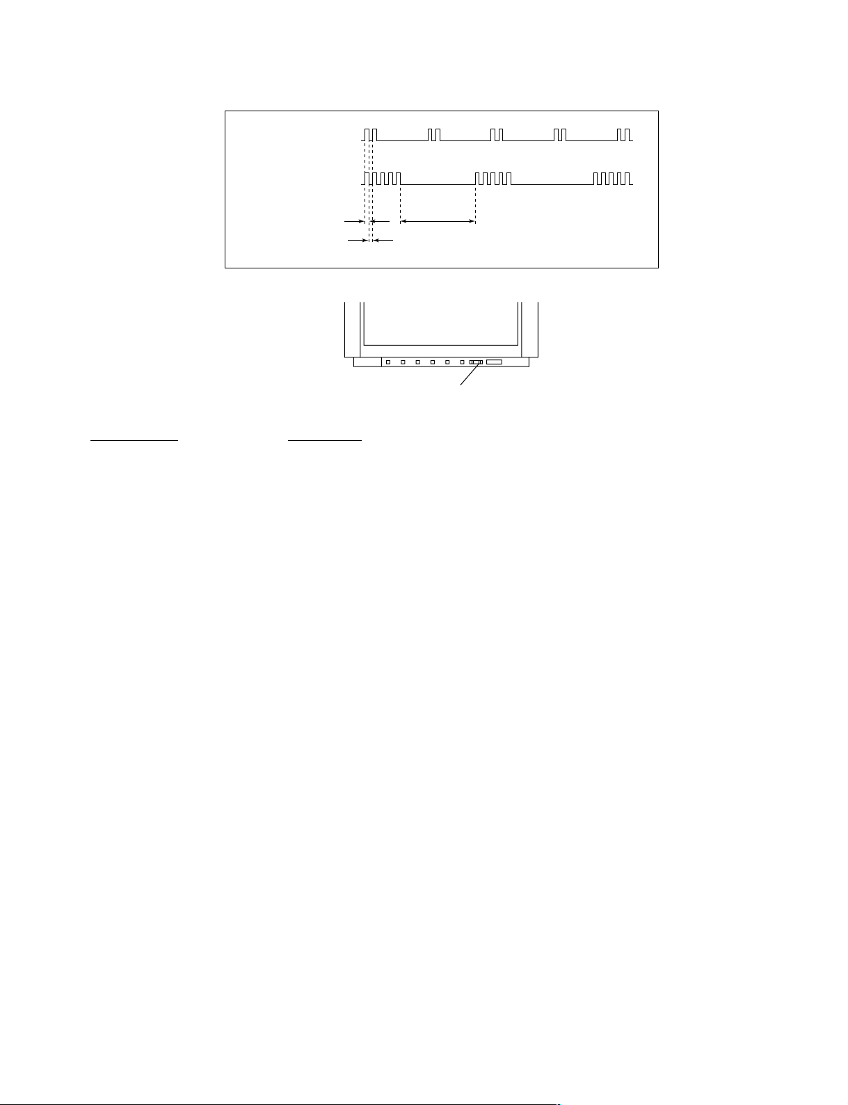
2. DISPLA Y OF STANDBY/TIMER LIGHT FLASH COUNT
2 times
5 times
KV-XS29N90/XS29N93
RM-914
Lamp ON 0.3 sec.
Lamp OFF 0.3 sec.
Lamp OFF 3 sec.
STANDBY/SLEEP lamp
Diagnostic Item Flash Count*
+B overcurrent/overvoltage 2 times
Vertical deflection stopped
White balance failure 5 times
* One flash count is not used for self-diagnostic.
3. STOPPING THE STANDBY/TIMER FLASH
Turn off the power switch on the TV main unit or unplug the power cord from the outlet to stop the STANDBY/TIMER lamp
from flashing.
– 5 –
KV-XS29N90/XS29N93
RM-914
4. SELF-DIAGNOSTIC SCREEN DISPLAY
For errors with symptoms such as “power sometimes shuts off” or “screen sometimes goes out” that cannot be confirmed, it
is possible to bring up past occurances of failure for confirmation on the screen:
[To Bring Up Screen Test]
In standby mode, press buttons on the remote commander sequentially in rapid succession as shown below:
[Screendisplay] / channel [5] / Sound volume [-] / Power ON
˘
Note that this differs from entering the service mode (mode volume [+]).
Self-Diagnosis screen display
SELF DIAGNOSTIC
002 : 000
003 : 000
004 : 000
005 : 001
101 : 000
Numeral "0" means that no fault has been detected.
Numeral "1" means a fault has been detected.
5. HANDLING OF SELF-DIAGNOSTIC SCREEN DISPLAY
Since the diagnostic results displayed on the screen are not automatically cleared, always check the self-diagnostic screen
during repairs. When you have completed the repairs, clear the result display to “0”.
Unless the result display is cleared to “0”, the self-diagnostic function will not be able to detect subsequent faults after
completion of the repairs.
[Clearing the result display]
To clear the result display to “0”, press buttons on the remote commander sequentially as shown below when the diagnostic
screen is being displayed.
Channel [8] / 0
[Quitting Self-diagnostic screen]
To quit the entire self-diagnostic screen, turn off the power switch on the remote commander or the main unit.
– 6 –
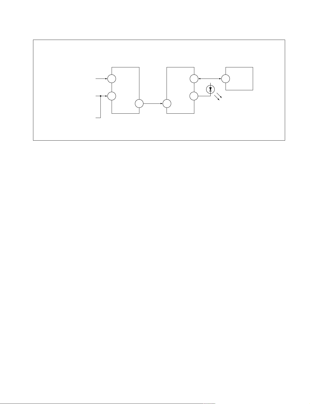
6. SELF-DIAGNOSTIC CIRCUIT
KV-XS29N90/XS29N93
RM-914
FROM
CRT
FROM
[+B] Q604 C
[V] Q509/507
IC301
Y/CHROMA JUNGLE
IK-IN
MP/
18 51
PROTECT
SDA
4635
IC001
SYSTEM
IO-8DAT
O-LED
IO-SDAT
MEMORY
B-DAT
54521
IC003
[+BovercurrentªOCPº] Occurs when an overcurrent on the +B(135) line is detected by Q604. If Q604 go to ON
and the voltage to pin 18 of IC301 should go down when V.SYNC is more than seven
verticals in a period, the unit will automatically turn off.
[Verticaldeflectionstopped] Occurs when an absence of the vertical deflection pulse is detected by Q509 and IC001
shut down the power supply.
[Verticaldeflectionovercurrent] Occurs when an overcurrent on V drive line is detected by Q507. Power supply will be
shut down when detect this by IC001.
[Whitebalancefailure] If the RGB levels* do not balance or become low level within 5 seconds, this error will be
detected by IC301. TV will stay on, but there will be no picture.
* (Refers to the RGB levels of the AKB detection Ref pulse that detects IK.)
– 7 –
SECTION 2
1 Two screws (Washer head)
(+P 4 × 16)
3 Four screws
(+BVTP 4 × 16)
2 Two screws
(+BVTP 3 × 12)
2 Bracket, speaker
1 Chassis assy
1 Eight screws
(+BVTP 4 × 16)
2 Rear cover
4 One screw
(+BVTP 4 × 16)
3 Three screws
(+BVTP 4 × 16)
1 3D Speaker box assy
Black wire
Red wire
DISASSEMBLY
KV-XS29N90/XS29N93
RM-914
2-1. 3D SPEAKER BOX REMOVAL
– 24 –
2-2. REAR COVER REMOVAL
2-3. SPEAKER REMOVAL
2-4. CHASSIS ASSY REMOVAL
Multi button
Two screws
One screw
(+BVTP 3 × 12)
2-5. F BRACKET REMOVAL
2 Two screws
(+BVTP 3 × 12)
3 F Board bracket
5 Two claws
1 Three connectors
6 F board
– 25 –
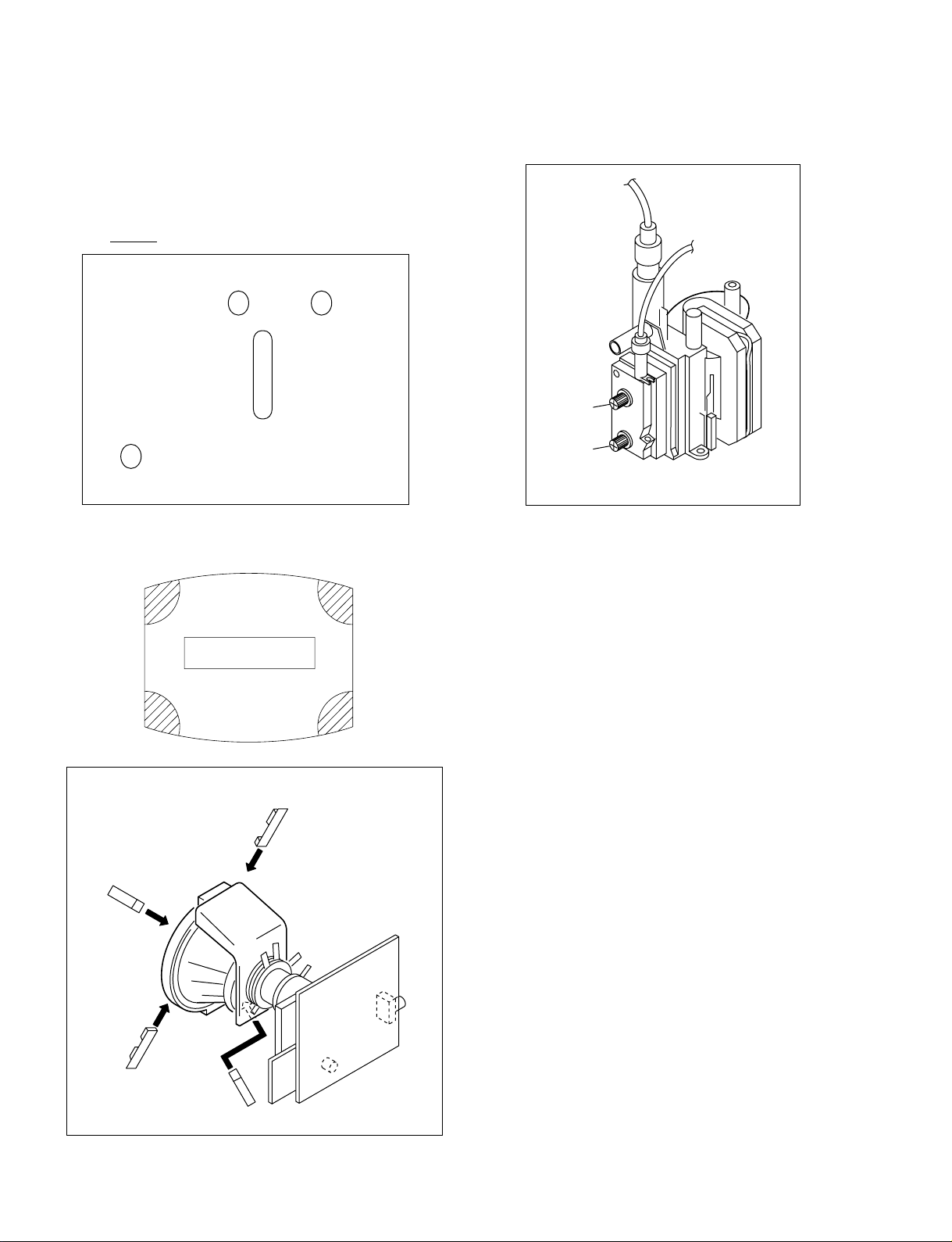
2-7. REPLACEMENT OF PARTS
For replacement of the Control Button and Light Guide, unscrew them, exchange
with the new parts, and fix them with screws (+BVTP) respectively.
2-7-1. REPLACEMENT OF CONTROL BUTTON
2-6. SERVICE POSITION
(Note: Remove F Bracket first.)
2-7-2. REPLACEMENT OF LIGHT GUIDE
KV-XS29N90/XS29N93
RM-914
KV-XS29N90/XS29N93
One screw
(+BVTP 3 × 12)
Two screws
(+BVTP 3
×
12)
Two screws
(+BVTP 3
×
12)
2 Two claws
3 Terminal bracket
3 Two screws
(+BVTP 3
×
12)
PWB holder
J4 Board
(KV-XS29N93 only)
7
5
6
1 Three connectors
2 One claw
3 D3 board
B7 board
B5 board
1 One claw
3 Two connectors
6 One screw (+BVTP 3
× 12 with washer)
1 Two connectors
4 Four claws
5 H5 Board
2 Four connectors
2-8. D3 BOARD REMOVAL
– 26 –
2-9. TERMINAL BRACKET REMOVAL
2-10. B5 and B7 BOARDS REMOVAL
RM-914
2-11. H5 BOARD REMOVAL
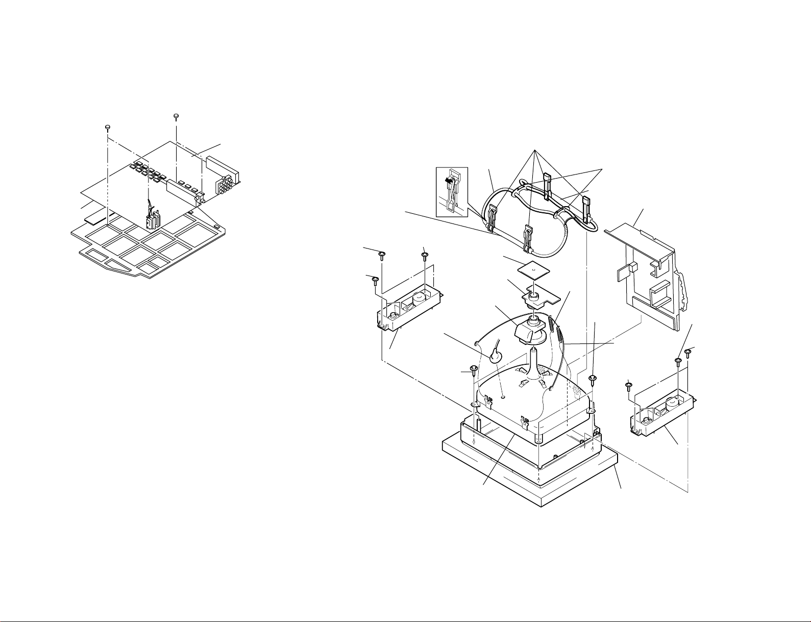
4 B3 Board
5 A Board
1 Two screws
(+BVTAP 3
× 12)
2 Two screws
(+BVTAP 3
× 12)
2-12. A AND B3 BOARDS REMOVAL
!¡ Cushion
!º Picture Tube
9 Two screws
(Tapping)
9 Two screws
(Tapping)
!¢ Earth Assy,
Coating
!∞ Tension
spring
6 Deflection
yoke
4 C Board
1 Coil Demagnetic
!• Four DGC Clips
!¶ Holder, Degause coil
5 VM Board
3 Cushion (50 × 550)
DGC
3 Cushion (50 × 550)
DGC
!§ Chassis Assy
7 Anode cap
8 Speaker Bracket Assy (L)
!™ Speaker Bracket Assy (R)
2 Two screws
(washer head)
(+P 4 × 16)
!ª Two screws
(+BVTP 3 × 12)
@º Four screws
(+BVTP 4 × 16)
2 Two screws
(washer head)
(+P 4 × 16)
!· Two screws
(+BVTP 4 × 16)
@º Four screws
(+BVTP 4 × 16)
2-13. PICTURE TUBE REMOV AL
– 27 –
KV-XS29N90/XS29N93
RM-914
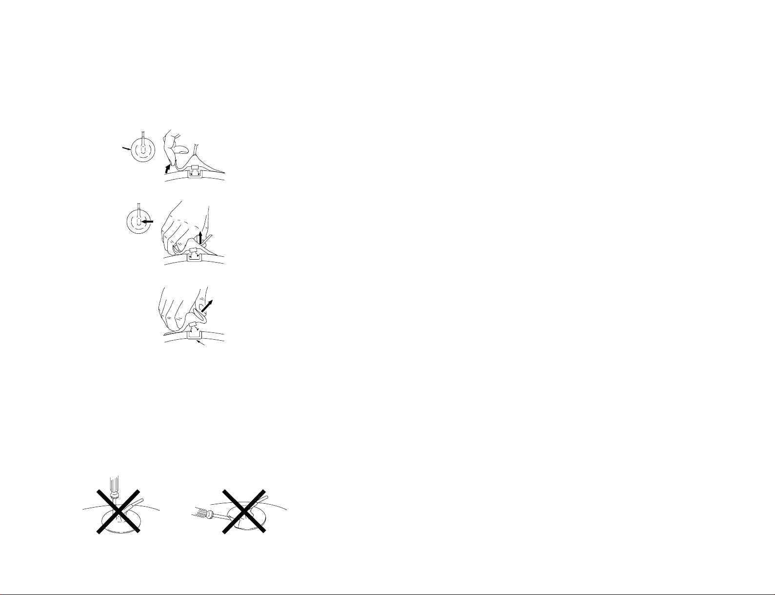
•REMOVAL OF ANODE-CAP
Anode button
a
a
b
b
c
NOTE : After removing the anode, short circuit the anode of the picture tube and
the anode cap to the metal chassis, CRT shield or carbon paint on the
CRT.
•REMOVING PROCEDURES
1 Turn up one side of the rubber cap in the direction indicated by the arrow a.
KV-XS29N90/XS29N93
RM-914
– 28 –
2 Using a thumb pull up the rubber cap firmly in the direction indicated by the arrow b.
3 When one side of the rubber cap is separated from the anode button, the anode-cap
can be removed by turning up the rubber cap and pulling it up in the direction of the
arrow c.
• HOW TO HANDLE AN ANODE-CAP
1 Do not damage the surface of anode-caps with sharp shaped objects.
2 Do not press the rubber too hard so as not to damage the inside of anode-cap.
A metal fitting called the shatter-hook terminal is built into the rubber.
3 Do not turn the foot of rubber over too hard.
The shatter-hook terminal will stick out or damage the rubber.
SECTION 3
Neck assy
G2G1 G3
Behind the G2 edge
SET-UP ADJUSTMENTS
KV-XS29N90/XS29N93
RM-914
• The following adjustments should be made when a complete
realignment is required or a new picture tube is installed.
• These adjustments should be performed with rated power
supply voltage unless otherwise noted.
Controls and switches should be set as follows unless otherwise noted:
PICTURE control........................................................... normal
BRIGHTNESS control................................................... normal
................................................................................................................................................................................................................................
Preparation :
• In order to reduce the influence of geomagnetism on the set's
picture tube, face it east or west.
• Switch on the set's power and degauss with the degausser.
Perform the adjustments in the following order :
1. Beam Landing
2. Convergence
3. Focus
4. White Balance
Note : Test Equipment Required.
1. Color-bar/Pattern Generator
2. Degausser
3. Oscilloscope
Purity control
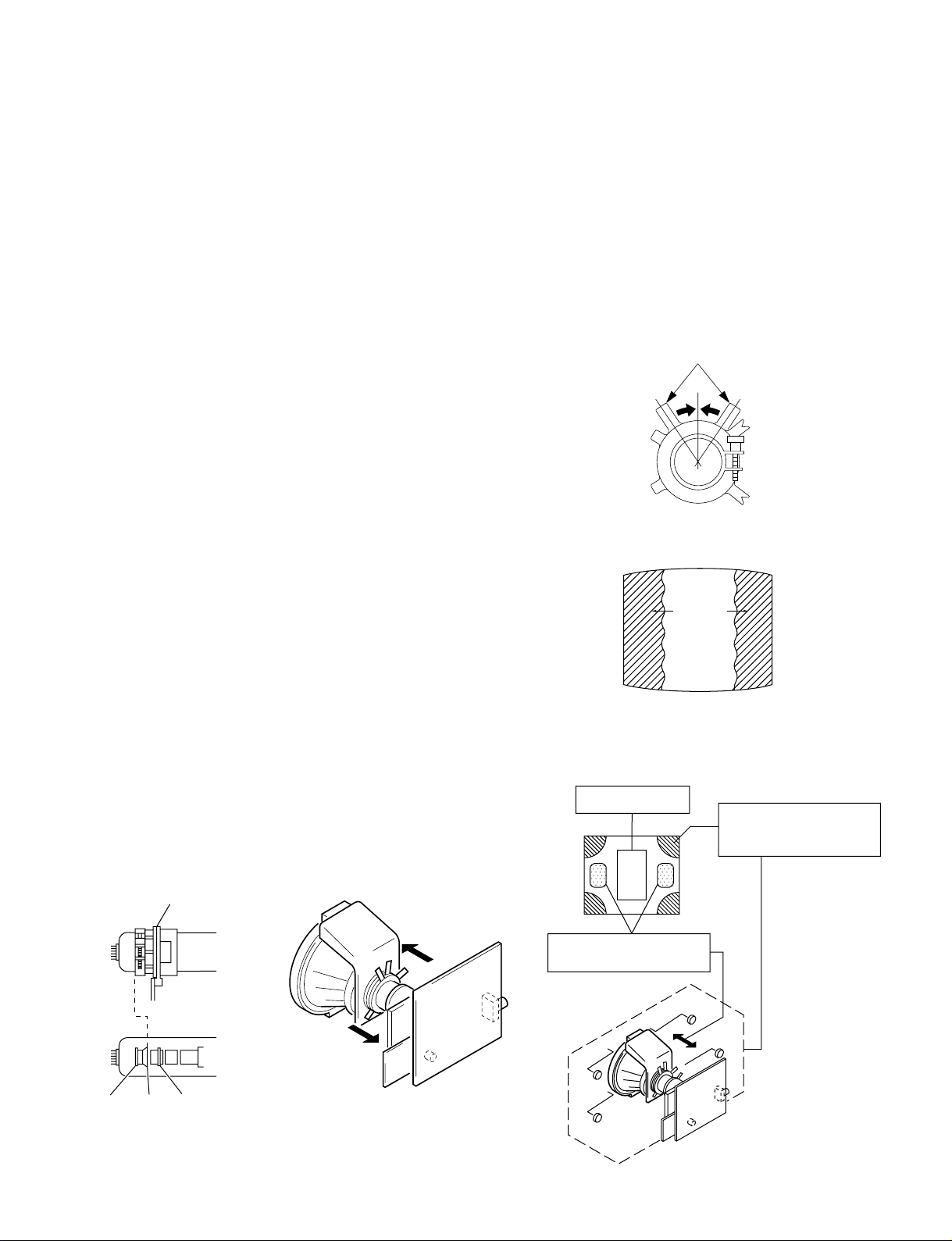
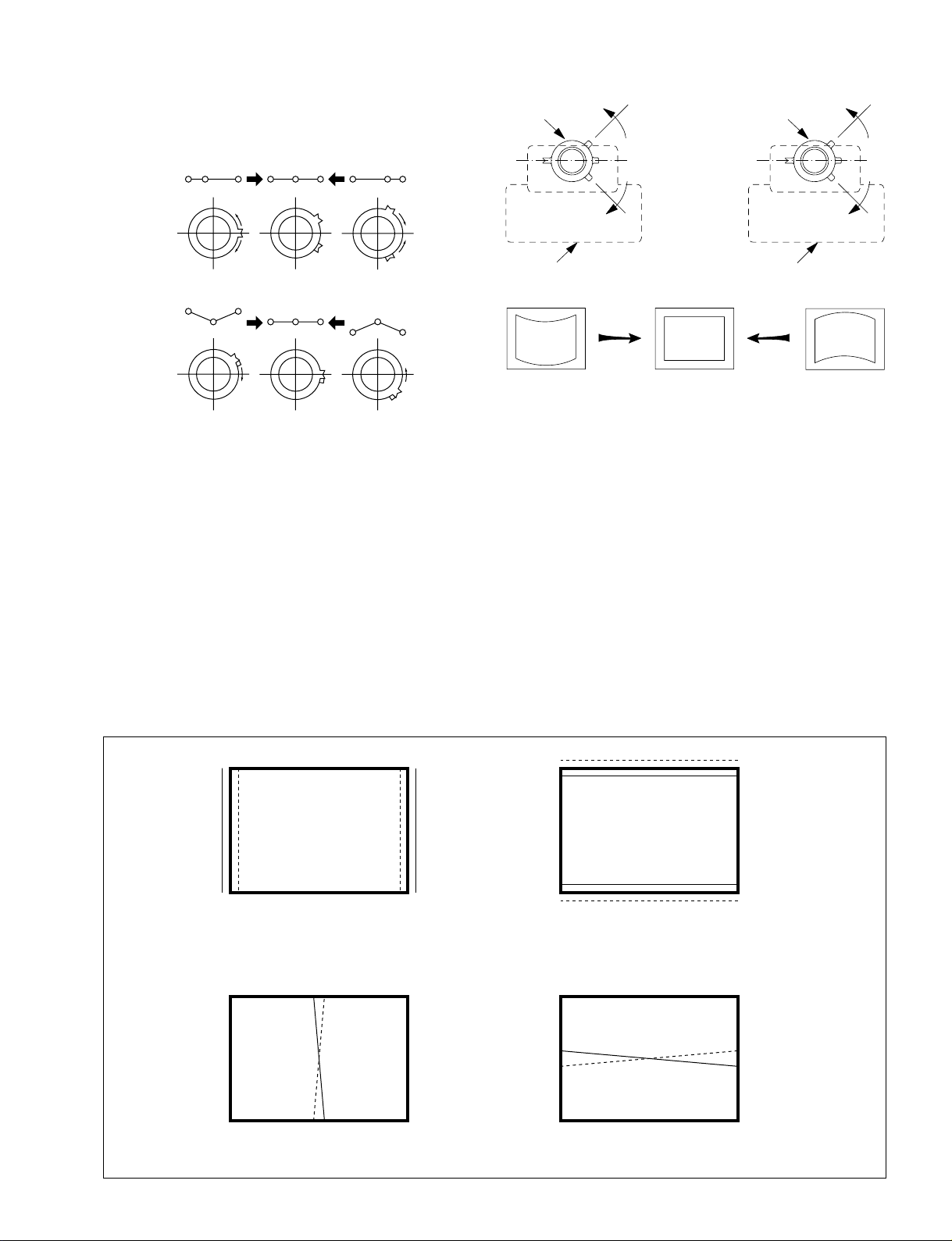
3-1. BEAM LANDING
1. Input a white signal with the pattern generator.
Contrast
Brightness
2. Position neck assy as shown in Fig3-2.
3. Set the pattern generator raster signal to a green raster.
4. Move the deflection yoke to the rear and adjust with the purity
control so that the green is at the center and the blue and the red
take up equally sized areas on each side.
(See Figures 3-1 through 3-4.)
5. Move the deflection yoke forward and adjust so that the entire
screen is green. (See Figure 3-2.)
6. Switch the raster signal to blue, then to red and verify the
condition.
7. When the position of the deflection yoke has been decided,
fasten the deflection yoke with the screws and DY spacers.
8. If the beam does not land correctly in all the corners, use a
magnet to adjust it.
(See Figure 3-5.)
}
normal
Red
Purity control
corrects this area.
b
a
Fig. 3-3
Blue
Green
Fig. 3-4
Disk magnets or rotatable
disk magnets correct these
areas (a-d).
Fig. 3-1
Fig. 3-2
– 29 –
c
Deflection yoke positioning
corrects these areas.
a
d
d
Fig. 3-5
b
c
KV-XS29N90/XS29N93
RM-914
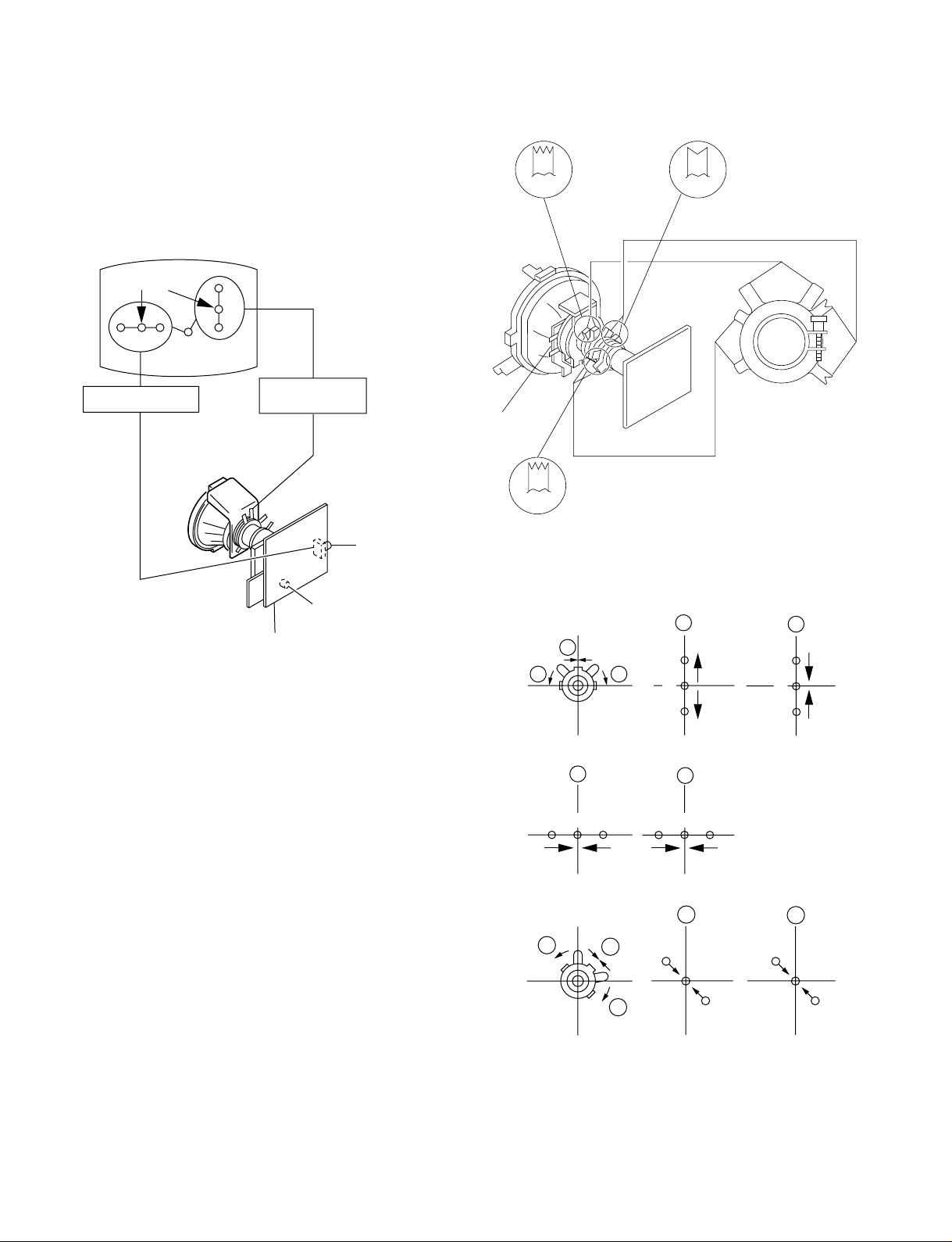
3-2. CONVERGENCE
Preparation :
• Before starting this adjustment, adjust the focus, horizontal size
and vertical size.
• Minimize the brightness setting.
• Provide dot pattern.
(1) Horizontal and Vertical Static Convergence
BMCPurity
BMC (Hexapole)
Purity
Center dot
R G B
H. STAT VR
R
G
B
V. STAT
Magnet
RV702
H. STAT
RV701
SCREEN (G2)
C Board
1. (Moving horizontally), adjust the H.STAT control so that the
red, green and blue dots are on top of each other at the center of
the screen.
2. (Moving vertically), adjust the V.STAT magnet so that the red,
green and blue dots are on top of each other at the center of the
screen.
3. If the H.STAT variable resistor cannot bring the red, green and
blue dots together at the center of the screen, adjust the
horizontal convergence with the H.STAT variable resistor and
the V.STAT magnet in the manner given below.
(In this case, the H.STAT variable resistor and the V.STAT
magnet influence each other, so be sure to perform adjustments
while tracking.)
DY pocket
V.STAT
1 V. STAT
b b
2 H. STAT VR
R
3
b
V.STAT
a
a
a
G
B
B
G
R
b
R
G
B
a
b
B
G
R
b
a
R
G
b
B
B
G
R
– 30 –
Blue
Red
VM board
Blue
Red
VM board
Neck assy Neck assy
4 BMC (Hexapole) Magnet.
If the red, green and blue dots are not balanced or aligned, then
use the BMC magnet to adjust in the manner described below.
RG B R G B R GB
KV-XS29N90/XS29N93
RM-914
RB
G
RG
GB
RB
5 Y separation axis correction magnet adjustment.
1. Receive the cross-hatch signal and adjust [PICTURE] to [MIN]
and [BRIGHTNESS] to [STANDARD] .
2. Adjust the Y separation axis correction magnet on the neck
assembly so that the horizontal lines at the top and bottom of
the screen are straight.
(2) Dynamic Convergence Adjustment
Preparation:
• Before starting this adjustment, adjust the horizontal static
convergence and the vertical static convergence
Note
1. The Red and Blue magnets should be equally far from the
horizontal center line.
2. Do not separate the Red and Blue magnets too far. (Less than
8 mm)
RB
B
R
TLH TLV
RB
R
B
YCH XCV
– 31 –
KV-XS29N90/XS29N93
RM-914
TLV Rotate TLV-2 VOL (29”, 34”) on DY
Rotate TLV VOL (25”) on DY
XCV Rotate XCV Adj core on DY
YCH Rotate YCH VOL on DY
TLH Insert TLH Correction Plate to DY Pocket (Left or
Right)
ON DY:
YCH
TLV1
XCV
TLV2
3-3. FOCUS ADJUSTMENT
Adjust FOCUS control on the flyback transformer for the best
focus.
Focus
Screen
FLYBA CK TRANSFORMER (T503)
(3) Screen-corner Convergence
ba
a-d : screen-corner
misconvergence
cd
Fix a Permalloy assy corresponding to the misconverged
areas.
a
b
d
Permalloy assembly
c
– 32 –
KV-XS29N90/XS29N93
RM-914
3-4. G2 (SCREEN) AND WHITE BALANCE
ADJUSTMENTS
1. G2 (SCREEN) ADJUSTMENT
1) Set the PICTURE to normal.
2) Put to VIDEO input mode without signals.
3) Connect R, G and B of the C board cathode to the oscilloscope.
4) Adjust BRIGHTNESS to obtain the cathode voltage to the value
below.
5) Adjust G2 (screen) on the FBT until picture shows the point
before cut off.
Cathode setting voltage:
180V ±2(VDC)...29"
0 V
2. WHITE BALANCE ADJUSTMENT
1) Set to Service Mode (Refer Section 4-1: ADJUSTMENTS
WITH COMMANDER).
2) Input white raster signal.
3) Set the PICTURE to minimum.
4) Select GCT (WHB 4) and BCT (WHB 5) with [1] and [4], and
adjust the level with
5) Set the PICTURE to maximum.
6) Select GDR (WHB 1) and BDR (WHB 2) with [1] and [4], and
adjust the level with
7) Write into the memory by pressing
3. SUB BRIGHT ADJUSTMENT
1) Set to service mode.
2) Input a staircase signal of black to white from the pattern
generator.
3) BRIGHTNESS ....50%.
PICTURE ............MINIMUM
4) Select SBR (WHB7) with [1] and [4], and adjust SBR (WHB7)
level with
dimly lit.
[3] and [6] so that the second stripe from the right is
[3] and [6] for the best white balance.
[3] and [6] for the best white balance.
[MUTING] then [0].
White
second from the right
Black
– 33 –
KV-XS29N90/XS29N93
RM-914
4-1. ADJUSTMENTS WITH COMMANDER
Service adjustments are made with the RM-914 that come with
this unit.
a. ENTERING SERVICE MODE
With the unit on standby
↓
[DISPLAY]
↓
5
↓
VOL (+)
↓
[POWER]
This operation sequence puts the unit into service mode.
b. METHOD OF CANCELLATION FROM SERVICE
MODE
Set the standby condition (Press [POWER] button on the commander),
then press [POWER] button again, hereupon it becomes TV mode.
c. METHOD OF WRITE INTO MEMORY
1) Set to Service Mode.
2) Press [1] (UP) and [4] (DOWN), select an item of adjustment.
3) Press [MUTING] button and it will indicate WRITE on the screen.
4) Press [0] button to write into memory.
d. MEMORY WRITE CONFIRMATION METHOD
1) After adjustment, pull out the plug from AC outlet, and then
plug into AC outlet again.
2) Turn the power switch ON and set to Service Mode.
3) Call the adjusted items again to confirm adjustments were made.
The screen display is :
SECTION 4
CIRCUIT ADJUSTMENTS
1, 4 Select the adjustment item.
↓
3, 6 Raise/lower the data value.
↓
[MUTING] Writes.
↓
- Executes the writing.
7, - All the data becomes the values in memory.
8, - All user control goes to the standard state.
5, - Service data initialization (Be sure not to use
2, - Write 50Hz adjustment data to 60Hz, or vice
usually.)
versa.
MTS
1
4
7
SOUND
MODE
PIC MODE
WAKE UP
SLEEP
CABLE
AUTO
PROGRAM
ADD/ERASE
DISPLAYMUTING
VIDEO
2
5
8
0
SURROUND
POWER
TV
3
6
9
FAVORITE
MENU
RETURN
Device Name
GEO
024S
Suffix No
(OEM Code)
Software version
Item Name
Item No
00
1.0C
Marking of virgin NVM
Data
HPS 1C SERVICE
Mode
p
59 7F 000A0
Total Power-On time (hours)
50
RM-914
PAL, SECAM : 50
NTSC : 60
– 34 –
4-2. ADJUSTMENT METHOD
Item Number 00 of device GEO
This explanation uses H-Position as an example.
1. Select “GEO 00 HPS” with the 1 and 4 buttons.
2. Raise/lower the data with the 3 and 6 buttons.
3. Select the optimum state. (The standard is 1F for P AL reception.)
4. Write with the
WRITE.)
5. Execute the writing with the - button. (The WRITE
display will be changed to red color while excuting, and back
to SERVICE.)
[MUTING] button. (The display changes to
KV-XS29N90/XS29N93
Use the same method for all Items. Use 1 and 4 to select the
adjustment item, use 3 and 6 to adjust, write with
then execute the write with -.
Note : 1. In
[WRITE], the data for all items are written into memory
together.
2. For adjustment items that have different standard data
between 50Hz or 60Hz, be sure to use the respective
input signal after adjustment.
[MUTING],
RM-914
GEO 00
024S 1.0C
GEO 00
024S 1.0C
GEO 00
024S 1.0C
1F SERVICE 50HPS
7F 0 000A59
1F WRITE 50HPS
7F 0 000A59
Written with [MUTING]
1F SERVICE 50HPS
7F 0 000A59
GREEN
Adjusted with [3]
and [6] buttons.
GREEN
RED
The WRITE display
then the display
returns to a green
SERVICE.
Write executed with [0]
– 35 –
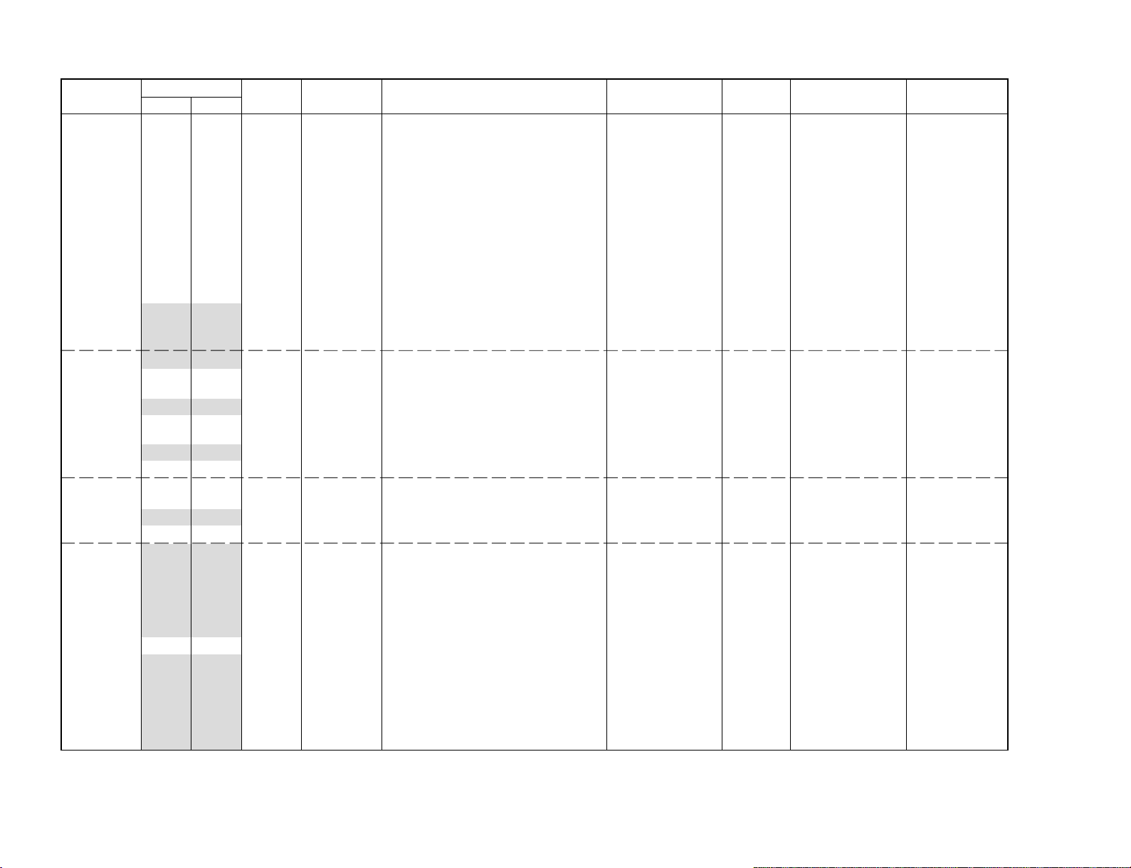
Adjustment Item Table
Device Functionality Note Data Range Function Note for Register Slava RAM Address
Name No Name Different Data No. (bit) Address (bit)
GEO 0 HPS 7 3F H Position 50/60Hz 12 (7-2) CXA2130S(88H) 9A (7-2)
WHB 0 RDR 1F 3F R Drive DYNAMIC/others 09 (7-2) CXA2130S(88H) A7 (7-2)
– 36 –
SAJ 0 PMX 36 3F Picture Maximum Data 03 (7-2) CXA2130S(88H) 105
VP 0 EHT 5 0F EHT Comp 50/60HLC 15 (3-0) CXA2130S(88H) 9D (3-0)
1 HSZ 1F 3F H Size 50/60Hz 11 (7-2) 99 (7-2)
2 PAP 1F 3F Pin Amp 50/60Hz 13 (7-2) 9B (7-2)
3 TLT 7 0F Trapezium 50/60Hz 15 (7-4) 9D (7-4)
4 VPS 1F 3F V Position 50/60Hz 0F (7-2) 97 (7-2)
5 VSZ 1F 3F V Size 50/60Hz 0E (7-2) 96 (7-2)
6 SCO 7 0F S Correction 50/60Hz 10 (7-4) 98 (7-4)
7 VLN 7 0F V Linearity 50/60Hz 10 (3-0) 98 (3-0)
8 BOW 7 0F AFC Bow 50/60Hz 16 (7-4) 9E (7-4)
9 AGL 7 0F AFC Angle 50/60Hz 16 (3-0) 9E (3-0)
10 UPN 1F 3F Upper Pin 50/60Hz 14 (7-2) 9C (7-2)
11 LPN 2F 3F Lower Pin 50/60Hz 18 (7-2) A0 (7-2)
12 HBL 1 1 H Blanking on/off 18 (1) ID (1)
13 LBL 0F 0F Left H Blanking 50/60Hz 17 (7-4) 9F (7-4)
14 RBL 2 0F Right H Blanking 50/60Hz 17 (3-0) 9F (3-0)
1 GDR 1F 3F G Drive DYNAMIC/others 0A (7-2) A8 (7-2)
2 BDR 1F 3F B Drive DYNAMIC/others 0B (7-2) A9 (7-2)
3 RCT 7 0F R Cutoff SECAM/others 07 (3-0) AB (3-0)
4 GCT 7 0F G Cutoff SECAM/others 08 (7-4) AC (7-4)
5 BCT 7 0F B Cutoff SECAM/others 08 (3-0) AC (3-0)
6 BMN 15 1F Brightness Minimum Data 06 (7-2) 106
7 SBR 1F 3F Sub Brightness Control 06 (7-2) 107
1 SHU 8 0F Sub Hue Control TV/Video 05 (7-2) 108
2 SSH 8 0F Sub Sharpness Control TV/Video 07 (7-4) 109
3 SCL 1F 3F Sub Color Control NTSC/others 04 (7-2) 10A
1 GMA 2 03
2 YDL 0D 0F Y Delay
3 SST 1 03 SECAM ID Start Position 1B (1-0) 73 (1-0)
4 SSP 1 03 SECAM ID Stop Position 1B (3-2) 73 (3-2)
5 SLV 2 03 SECAM ID Level 1C (1-0) 74 (1-0)
6 SBF 22 3F SECAM BELL fO 1C (7-2) 74 (7-2)
7 DYC 1 1 Dynamic Color on/off 0A (1) 62 (1)
8 ABL 1 1 ABL Mode Switching (except STANDARD mode) 09 (1) 61 (1)
9 VTH 1 1 ABL Detection Vth Switching 09 (0) 61 (0)
10 SFO 1 1 FO Switching for Sharpness NTSC/others 05 (1) 34A (1)
11 DCX 1 1 DC Trans. Ratio Switching 06 (1) 5E (1)
12 SHT 1 1 Pre-/Overshoot ratio Switch NTSC/others 06 (0) 34B (0)
Gamma Correction (separated in STANDARD mode
)
PAL/SECAM/NTSC/DVD
NTSC/others 0B (1-0) 359 (1-0)
0C (3-0) 35C (3-0)
KV-XS29N90/XS29N93
RM-914
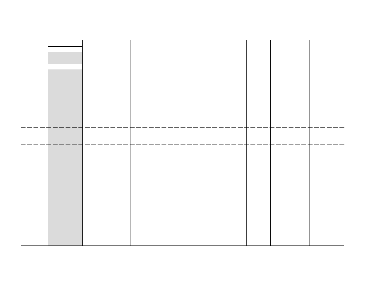
Adjustment Item Table
Device Functionality Note Data Range Function Note for Register Slava RAM Address
Name No Name Different Data No. (bit) Address (bit)
VP 13 HDW 0 1 H Drive Pulse Width Switch 00 (6) 58 (6)
AP 0 BCS 2 3 Bass Center Shift #4 (3-0) TDA7315(80H) 34C (1-0)
– 37 –
MSP 0 WST 15 FF W/G Stereo Threshold MSP3415D(84H) 165
14 AFC 1 03 AFC Gain Control TV/Video/Text 0F (1-0) A5 (1-0)
15 HOS 7 0F H Oscillation 0C (7-4) 64 (7-4)
16 HSS 0 1 Slice Level of H Sync Sep. 0D (1) 65 (1)
17 VSS 0 1 Slice Level of V Sync Sep. 0D (0) 65 (0)
18 HMS 1 1 Macro Vision C/m off/on 50/60Hz 0E (0) 96 (0)
19 YUV 0 1 YUV Switch Control 01 (0) 59 (0)
20 CDV 1 3
21 RON 1 1 R ON not memorized 01 (3) 59 (3)
22 GON 1 1 G ON not memorized 01 (2) 59 (2)
23 BON 1 1 B ON not memorized 01 (1) 59 (1)
24 PON 1 1 P ON not memorized 00 (7) 58 (7)
25 BLK 0 1 BLK Off 12 (0) 6A (0)
26 VMC 0 1 VM Off 13 (0) 6B (0)
1 TCS 1 3 Treble Center Shift #5 (3-0) 34D (1-0)
2 TRF 2 3 RF T reble Offset #5 (3-0) 356 (1-0)
1 WBT EC FF W/G Bilingual Threshold 166
2 WLL 5 FF W/G Monaural Threshold 167
3 WAC 1 0F W/G Agreement Count 168
4 WDL 30 FF W/G Search Delay 169
5 NDL 20 FF NICAM Search Delay 16A
6 SDL 10 FF Stereo status Read Delay 16B
7 AGC 1 1 AGC Switch Auto/Constant 00BB (7) 116 (7)
8 REL 28 3F AGC Gain at Constant Mode 00BB (6-1) 116 (6-1)
9 CRM 0 1 Carrier muting on/off 00BB (9) 115 (9)
10 ACO 1 1 Audio Clock out on/off 0083 (5) 11A (5)
11 FP 1B 7F FM Prescale for non-M system 000E (14-8) 321
12 FPM 32 7F FM Prescale for M system 000E (14-8) 322
13 FH 36 7F FM Prescale for HDEV 000E (14-8) 323
14 FHM 65 7F FM Prescale for HDEV and M 000E (14-8) 324
15 WGP 1C 7F W/G Prescale 000E (14-8) 325
16 NIP 7F 7F NICAM Prescale 0010 (14-8) 14F
17 ERR 50 FF Auto FM switch Threshold 0021 (10-3) 174
18 VOL 6D FF Loud Speaker gain 7000h to 7ff0h 0000 (11-4) 352
CD mode for Video and RF under no signal
Video only 0D (5-4) 357 (5-4)
KV-XS29N90/XS29N93
RM-914
 Loading...