

SONY KV-T25SN81 Service Manual
SERVICE MANUAL
BG-1S
CHASSIS
MODEL COMMANDER DEST. CHASSIS NO.
KV-T25SN81
RM-870 New Zealand SCC-K37F-A
MODEL COMMANDER DEST. CHASSIS NO.
TRINITRON
®
COLOR TV
KV-T25SN81
RM-870
Power requirements 110-240 V AC, 50/60 Hz
Power consumption (W) Indicated on the rear of the TV
Television system B/G
Color system PAL, PAL 60, NTSC4.43, NTSC3.58(AV IN)
Stereo/Bilingual system NICAM Stereo/Bilingual B/G, A2 Stereo/Bilingual (German) B/G
Teletext Language English, German, Swedish, Italian, French, Spanish
Channel coverage VHF : 1 to 11 / UHF : 21 to 69 / CATV: S01 to S03, S1 to S41
Audio output (speaker) 5W × 2
Inputs Antenna: 75 ohms
Outputs Headphone jack: minijack
Picture tube 25 in.
Tube size (cm) 64 Measured diagonally
Screen size (cm) 60 Measured diagonally
Dimensions (w/h/d, mm) 613 × 542 × 472
Mass (kg) 32
SPECIFICATIONS
Note
VIDEO IN jacks: phono jacks
Video: 1 Vp-p, 75 ohms
Audio: 500 mVrms, high impedance
MONITOR OUT jacks: phono jacks
Video: 1 Vp-p, 75 ohms
Audio: 500 mVrms
CAUTION
SHORT CIRCUIT THE ANODE OF THE PICTURE TUBE AND
THE ANODE CAP TO THE METAL CHASSIS, CRT SHIELD, OR
CARBON PAINTED ON THE CRT, AFTER REMOVING THE
ANODE.
Design and specifications are subject to change without notice.
SAFETY-RELATED COMPONENT WARNING!!
COMPONENTS IDENTIFIED BY SHADING AND MARK ! ON
THE SCHEMA TIC DIAGRAMS, EXPLODED VIEWS AND IN THE
PARTS LIST ARE CRITICAL TO SAFE OPERATION. REPLACE
THESE COMPONENTS WITH SONY PARTS WHOSE PART
NUMBERS APPEAR AS SHOWN IN THIS MANUAL OR IN
SUPPLEMENTS PUBLISHED BY SONY.
– 2 –

KV-T25SN81
TABLE OF CONTENTS
Section Title Page Section Title Page
RM-870
SELF DIAGNOSIS FUNCTION ............................... 4
1. GENERAL.................................................................... 5
2. DISASSEMBLY
2-1. Rear Cover Removal............................................ 11
2-2. A Board Removal ................................................ 11
2-3. F1 Board Removal ............................................... 11
2-4. Service Position ................................................... 11
2-5. Replacement of Parts ........................................... 12
2-6. Demagnetization Coil Removal .......................... 12
2-7. Picture Tube Removal.......................................... 13
3. SET-UP ADJUSTMENTS
3-1. Beam Landing ...................................................... 14
3-2. Convergence......................................................... 15
3-3. Focus Adjustment ................................................ 17
3-4. G2 (Screen) and White Balance Adjustments..... 17
4. CIRCUIT ADJUSTMENTS
4-1. Adjustments with Commander ............................ 18
4-2. Adjustment Method ............................................. 19
4-3. A Board Adjustment after IC003 (Memory)
Replacement......................................................... 22
4-4. Picture Distortion Adjustment............................. 22
5. DIAGRAMS
5-1. Block Diagram ...................................................... 25
5-2. Circuit Boards Location ....................................... 29
5-3. Schematic Diagrams and Printed Wiring Boards. 29
(1) Sc hematic Dia gram of A Board ........................... 33
(2) Schematic Diagrams of A3, F1 and V1 Boards ... 37
(3) Sc hematic Diagrams of C and VM Boards .......... 45
5-4. Semiconductors ..................................................... 48
6. EXPLODED VIEW
6-1. Chassis .................................................................. 51
7. ELECTRICAL PARTS LIST ................................... 53
– 3 –
KV-T25SN81
RM-870
If no acknowledgement is returned from a device which is turned "ON", the device has a problem.
In this case, one of the LED's responding to the problem device will flicker a defined number of times.
Flickering is operated by lighting the LED's for 60ss each time.
The flickering frequency responding to each failed device is shown below.
SELF DIAGNOSIS FUNCTION
NONVOLATILE
Device
Flickering
Frequency
All the devices are checked one after another from the left of the table.
If an error is found, the responding LED will start flickering.
So, if more than 1 device have failed, only the one on the left side will flicker.
MEMORY
1
—
—
Y/C JUNGLE
(IC300)
3
—
—
—
—
TONE
CONTROL
(IC201)
6
– 4 –
SECTION 2
2
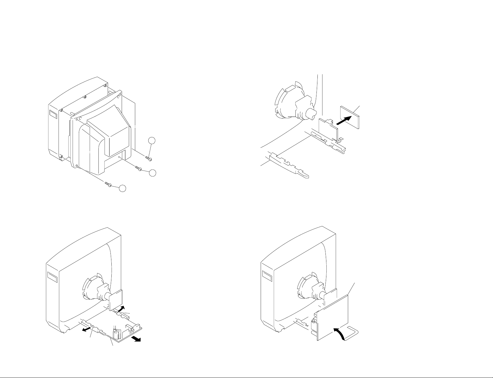
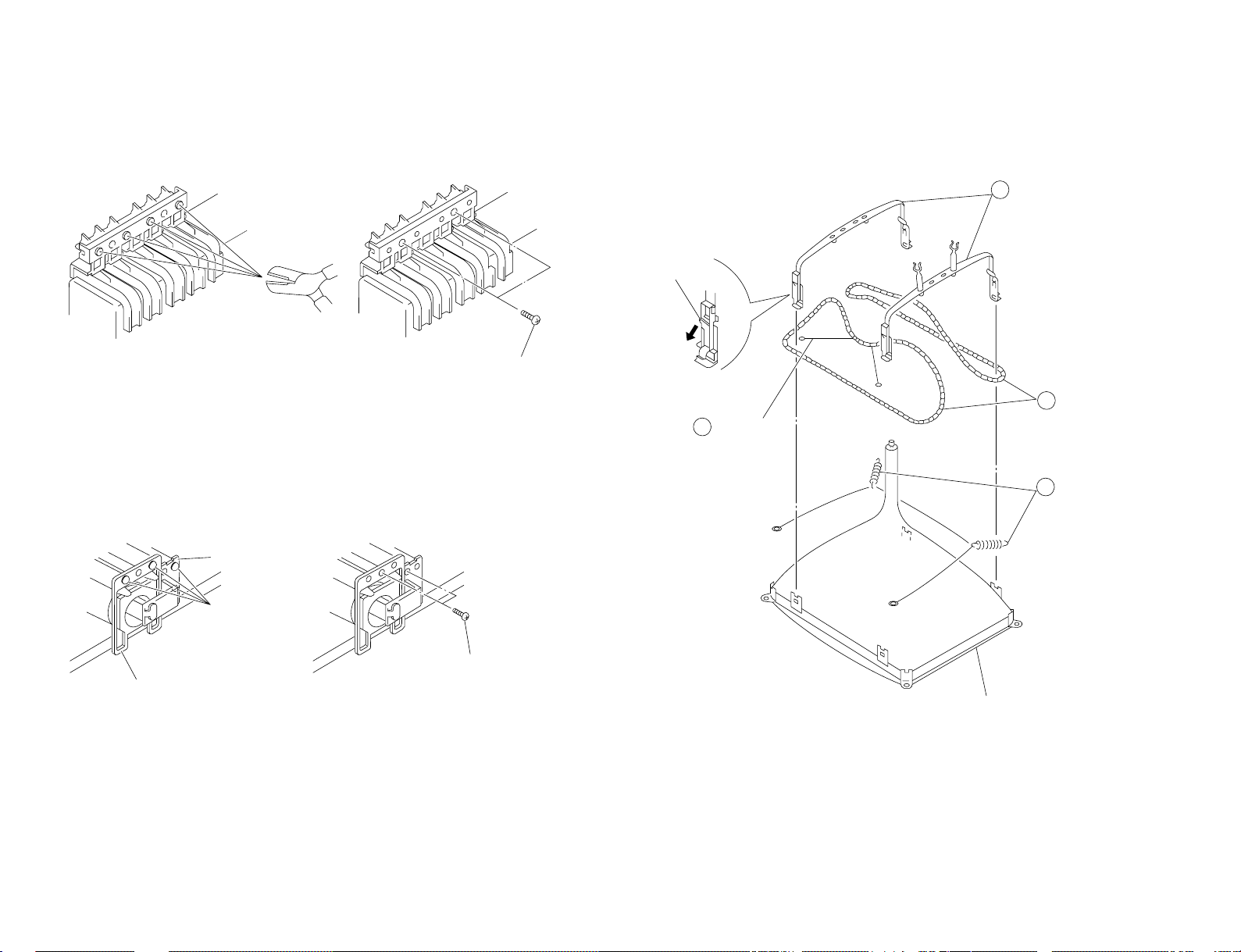
Two screws
(BVTP 4×16)
3
One screw
(BVTP 3×16)
1
Two screws
(BVTP 4×16)
Lever
Lever
A board
A board
F1 board
DISASSEMBLY
2-1. REAR COVER REMOVAL 2-3. F1 BOARD REMOVAL
– 11 –
2-2. A BOARD REMOVAL
2-4. SERVICE POSITION
KV-T25SN81
RM-870
KV-T25SN81
3
Demagnetization coil
4
Tension spring
Picture tube
2
DGC holder
1
DGC band
Remove the claw
Cut
Light guide
Power button
Two screws
(BVTP 3×12)
Two screws
(BVTP 3×12)
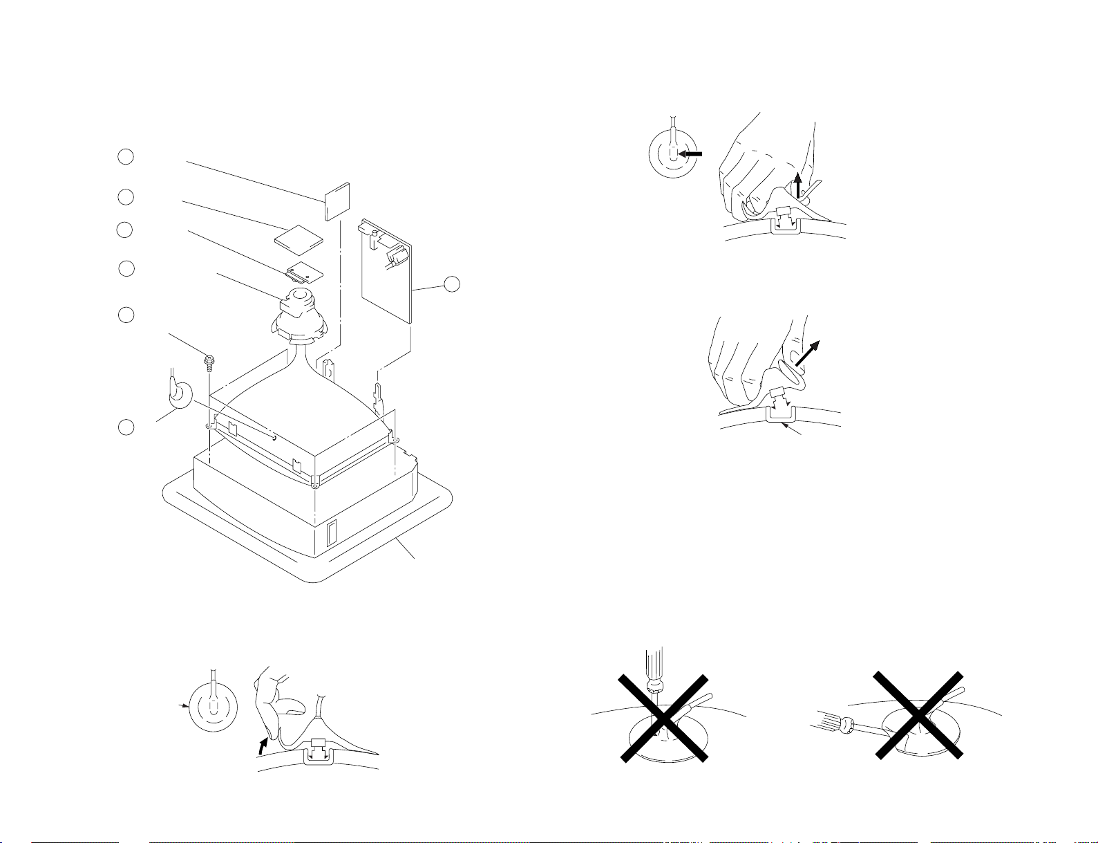
2-5. REPLACEMENT OF PARTS
For replacement of the Multi Button, Power Button and Light Guide, cut the welded portions
from them, exchange with the new parts, and fix them with screws (+BVTP) respectively.
2-5-1. REPLACEMENT OF MULTI BUTTON
– 12 –
2-5-2. REPLACEMENT OF POWER BUTTON AND LIGHT GUIDE
2-6. DEMAGNETIZATION COIL REMOVAL
RM-870
b
b
c
Anode button
a
a
2 A board
5 Deflection yoke
Cushion
6 Four screws
(Tapping screws)
1 Anode cap
4 C board
3 F1 board
7 VM board
– 13 –
2-7. PICTURE TUBE REMOVAL
NOTE : The picture tube for this model are upside-down, and the position for the anode-cap
and tension spring are changed accordingly.
2 Using a thumb press down then pull up the rubber cap firmly in the direction
indicated by the arrow b.
•REMOVAL OF ANODE-CAP
NOTE : After removing the anode, short circuit the anode of the picture tube and the
•REMOVING PROCEDURES
1 Turn up one side of the rubber cap in the direction indicated by the arrow a.
anode cap to the metal chassis, CRT shield or carbon paint on the CRT.
3 When one side of the rubber cap is separated from the anode button, the
anode-cap can be removed by turning up the rubber cap and pulling it up in the
direction of the arrow c.
• HOW TO HANDLE AN ANODE-CAP
1 Do not damage the surface of anode-caps with sharp shaped objects.
2 Do not press the rubber too hard so as not to damage the inside of anode-caps.
A metal fitting called the shatter-hook terminal is built into the rubber.
3 Do not turn the foot of rubber over too hard.
The shatter-hook terminal will stick out or damage the rubber.
KV-T25SN81
RM-870
KV-T25SN81
GREEN
BLUE RED
RM-870
SECTION 3
SET-UP ADJUSTMENTS
• The following adjustments should be made when a complete
realignment is required or a new picture tube is installed.
• These adjustments should be performed with rated power
supply voltage unless otherwise noted.
Controls and switch should be set as follows unless otherwise noted:
PICTURE control........................................................... normal
BRIGHTNESS control................................................... normal
................................................................................................................................................................................................................................
Preparation :
• In order to reduce the influence of geomagnetism on the set's
picture tube, face it east or west.
• Switch on the power and degauss with the degausser.
Perform the adjustments in the following order :
1. Beam Landing
2. Convergence
3. Focus
4. White Balance
Note : Test Equipment Required.
1. Color-bar/Pattern Generator
2. Degausser
3. Oscilloscope
Purity control
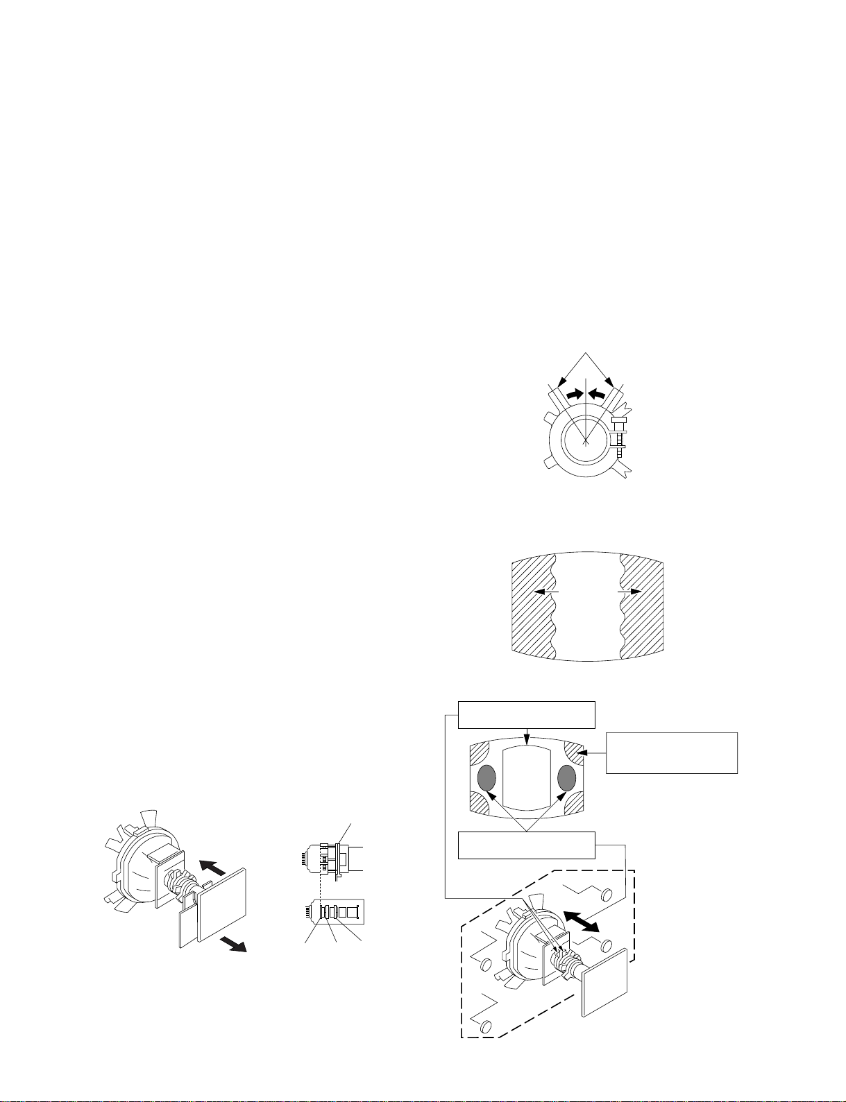
3-1. BEAM LANDING
1. Input a white signal with the pattern generator.
Contrast
Brightness
2. Position neck assy as shown in Figure 3-1.
3. Set the pattern generator raster signal to a green raster.
4. Move the deflection yoke to the rear and adjust with the purity
control so that the green is at the center and the blue and the red
take up equally sized areas on each side.
(See Figures 3-1 through 3-3.)
5. Move the deflection yoke forward and adjust so that the entire
screen is green. (See Figure 3-1.)
6. Switch the raster signal to blue, then to red and verify the
condition.
7. When the position of the deflection yoke has been decided,
fasten the deflection yoke with the screw.
8. If the beam does not land correctly in all the corners, use a
magnet to adjust it.
(See Figure 3-4.)
}
normal
Fig. 3-2
Fig. 3-3
Purity control corrects
this area.
a
b
Disk magnets or rotatable
disk magnets correct
these areas (a-d).
Fig. 3-1
Neck assy
G1 G2 G3
– 14 –
c
Deflection yoke positioning
corrects these areas.
b
d
d
Fig. 3-4
a
c
3-2. CONVERGENCE
Preparation :
• Before starting this adjustment, adjust the focus, horizontal size
and vertical size.
• Minimize the brightness setting.
• Provide dot pattern.
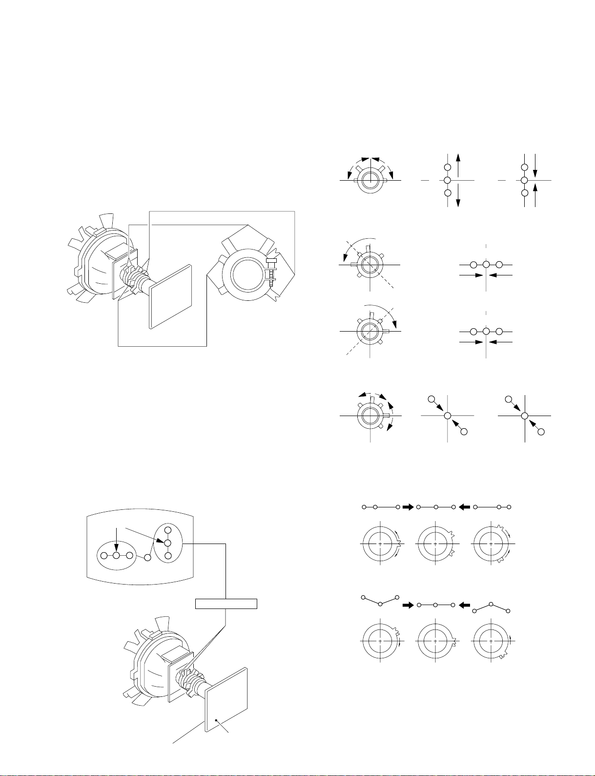
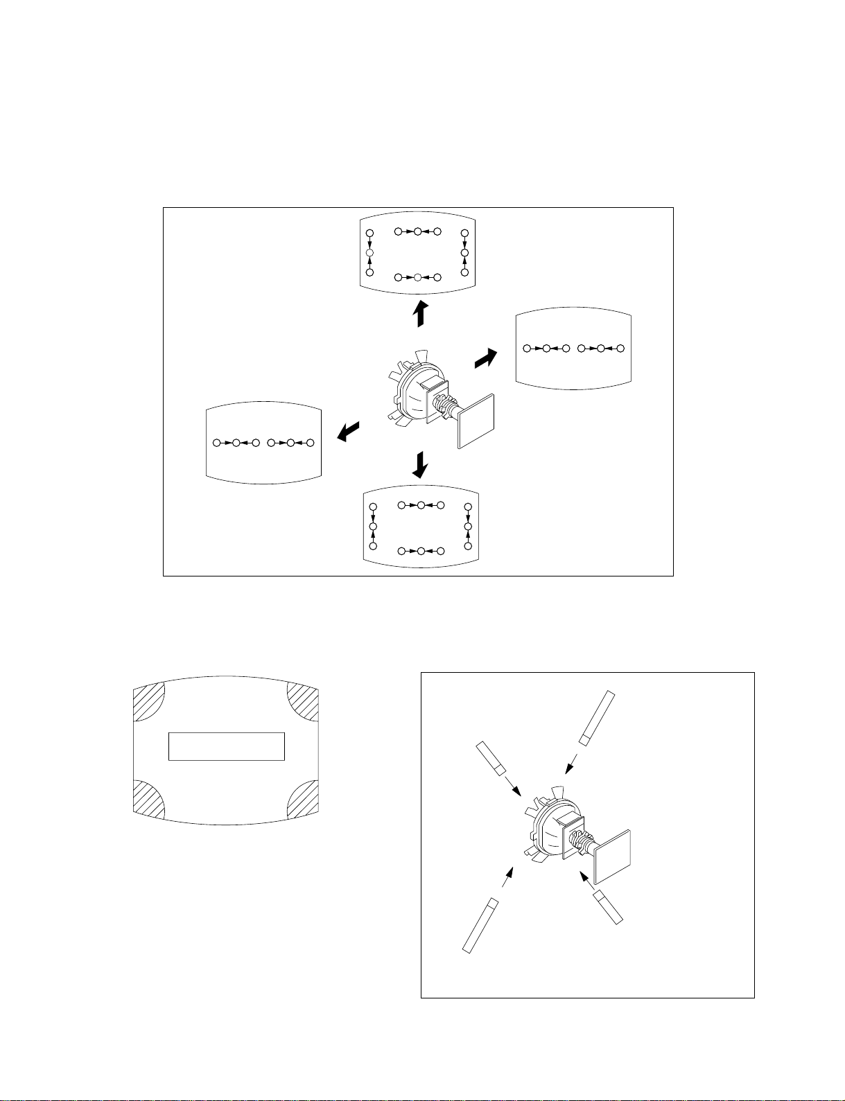
(1) Horizontal and Vertical Static Convergence
BMC (Hexapole)
Purity
• Operation of the V.STAT magnet.
If the V-STAT ma gnet is moved in the direction of the a and
b arrows, the red, green and blue dots move as shown below.
1
2
a
bb
a
ab
B
GG
R
R G B
B
R
a
KV-T25SN81
RM-870
V.STAT
1. (Moving vertically), adjust the V.STAT magnet so that the red,
green and blue dots in the center of the screen are separated
from each other.
2. Adjust the BMC (Hexapole) magnet so that the red, green and
blue dots are aligned in a straight line.
3. Adjust the BMC (Hexapole) magnet so that the red, green and
blue dots are balanced (ie. equal distance) on either side of the
green dot.
4. (Moving horizontally), adjust the H.STAT VR magnet so that
the red, green and blue dots converge on top of each other in
the center of the screen.
Center dot
R G B
R
G
B
3
b
b
a
b
a
R
G
b
B G R
B
G
B
• Operation of BMC (Hexapole) Magnet.
To align or balance the red, green and blue dots, adjust the BMC
(Hexapole) magnet as shown below.
RG B
RGB R GB
b
R
C board
V.STAT Magnet
RV 701
SCREEN (G2)
R
B
G
RGB
G
R
• The respective dot positions resulting from moving each magnet
interact, so be sure to perform adjustment while tracking.
Use the V. STAT magnet to adjust the red, green and blue dots
so they coincide at the center of screen (by moving the dots in
the horizontal direction).
– 15 –
B
KV-T25SN81
RM-870
(2) Dynamic Convergence Adjustment
Preparation :
• Before starting this adjustment, adjust the horizontal static
convergence and the vertical static convergence.
1. Slightly loosen the deflection yoke screws.
2. Remove the deflection yoke spacer.
3. Move the deflection yoke as shown in the figure below and
optimize the convergence.
4. Tighten the deflection yoke screws.
5. Install the deflection yoke spacer.
RGB RGB
R
G
RGB
B
B
R
G
R
B
RGB
G
R
RGBRGB
R
B
G
G
RGB
B
(3) Screen-corner Convergence
b
a-d : screen-corner
misconvergence
c
b
Fix a Permalloy assy
a
a
corresponding to the
misconverged areas
d
c
d
Permalloy assembly
– 16 –
 Loading...