

SONY KV-SW21M95 Service Manual
SERVICE MANUAL
BX1S
CHASSIS
MODEL COMMANDER DEST. CHASSIS NO.
KV-SW21M20 RM-GA002 South Africa
KV-SW21M80 RM-GA002 Pakistan
KV-SW21M95 RM-GA002 Russia SCC-V13N-A
MODEL COMMANDER DEST. CHASSIS NO.
(Except KV-SW21M95)
RM-GA002
(KV-SW21M95)
TRINITRON
®
COLOR TV

KV-SW21M20/M80/M95
RM-GA002
TABLE OF CONTENTS
Section Title Page
SELF DIAGNOSTIC FUNCTION................................... 3
1. DISASSEMBLY
1-1. 3D Box Removal.......................................................... 5
1-2. Rear Cover Removal .................................................... 5
1-3. Speaker Removal ......................................................... 5
1-4. Chassis Assy Removal ................................................. 5
1-5. Service Position ........................................................... 5
1-6. Terminal Bracket and J Board Removal ..................... 5
1-7. A Board Removal ........................................................ 6
1-8. Picture Tube Removal.................................................. 6
2. SET-UP ADJUSTMENTS
2-1. Beam Landing Adjustment .......................................... 8
2-2. Convergence Adjustment .............................................8
2-3. Focus Adjustment ...................................................... 10
2-4. G2 (SCREEN) Adjustments ...................................... 10
2-5 White Balance Adjustment ........................................ 10
3. CIRCUIT ADJUSTMENTS
3-1. Adjustment With Commander ................................... 11
3-2. Adjustment Method ................................................... 12
3-3. Picture Quality Adjustments...................................... 28
3-3-1. P MAX/Contrast Adjustment ......................... 28
3-3-2. Sub Color Adjustment .................................... 28
3-3-3. Sub Hue Adjustment ....................................... 28
3-3-4. Sub Bright Adjustment ................................... 28
3-4. Geometry Adjustments .............................................. 28
3-4-1. General Setting ............................................... 28
3-4-2. Pal 50Hz Normal Mode .................................. 29
Section Title Page
4. DIAGRAMS
4-1. Block Diagram ...........................................................30
4-2. Circuit Boards Location ............................................ 31
4-3. Schematic Diagram Information ............................... 31
4-3-1. A Board — (Block 001).................................. 32
4-3-2. A Board — (Block 002).................................. 34
4-3-3. A Board — (Block 003).................................. 36
4-3-4. A Board — (Block 004).................................. 38
4-3-5. A Board — (Block 005).................................. 40
4-3-6. A Board — (Block 006).................................. 42
4-3-7. A Board — (Block 007).................................. 44
4-3-8. C and J Boards Schematic Diagrams ............. 45
4-4. Voltage Measurement and Waveforms ...................... 46
4-5. Printed Wiring Boards ............................................... 49
4-6. Semiconductors .......................................................... 52
5. EXPLODED VIEWS
5-1. Picture Tube and Chassis........................................... 54
5-2 3D Speaker ................................................................. 54
6. ELECTRICAL PARTS LIST......................................... 56
OPERATING INSTRUCTIONS
CAUTION
SHORT CIRCUIT THE ANODE OF THE PICTURE TUBE AND THE
ANODE CAP TO THE METAL CHASSIS, CRT SHIELD, OR
CARBON PAINTED ON THE CRT, AFTER REMOVING THE
ANODE.
SAFETY-RELATED COMPONENT WARNING!!
COMPONENTS IDENTIFIED BY SHADING AND MARK ! ON THE
SCHEMATIC DIAGRAMS, EXPLODED VIEWS AND IN THE
PARTS LIST ARE CRITICAL TO SAFE OPERATION. REPLACE
THESE COMPONENTS WITH SONY PARTS WHOSE PART
NUMBERS APPEAR AS SHOWN IN THIS MANUAL OR IN
SUPPLEMENTS PUBLISHED BY SONY.
– 2 –
KV-SW21M20/M80/M95
SELF DIAGNOSTIC FUNCTION
The units in this manual contain a self diagnostic function. If an error occurs, the STANDBY (1) indicator will automatically
begin to flash. The number of times the STANDBY (1) indicator flashes translates to a probable source of the problem. If an
error symptom cannot be reproduced, the remote commander can be used to review the failure occurrence data stored in
memory to reveal past problems and how often these problems occur.
1. DIAGNOSTIC TEST INDICATORS
When an errors occurs, the STANDBY (1) indicator will flash a set number of times to indicate the possible cause of the
problem. If there is more than one error, the indicator will identify the first of the problem areas.
Result for all of the following diagnosis items are displayed on screen. No error has occurred if the screen displays a "0".
RM-GA002
Diagnosis
Item
Description
No Power
+B overcurrent
(OCP)
V-Protect (OVP)
IK (AKB)
Power supply
NG (+5V) for
Video Processor
No. of timer
STANDBY (1)
indicator flashes
Does not light
2 times
4 times
5 times
8 times
Diagnostic Result
on screen display
–
2:0
or
2:1 ~ 255
4:000
or
4:1 ~ 255
5:0
or
5:1 ~ 255
8:0
or
8:1 ~ 255
Probable Cause
Location
• Power cord is not plugged
in.
• Fuse is burned out (F600)
A board.
• H OUT (Q805) is shorted.
(A board)
IC751 is shorted. (C board)
•
• +13V is not supplied.
(A board)
• IC804 is faulty. (A board)
• Video OUT (IC1545) is
faulty. (A board)
• IC001 is faulty. (A board)
• Screen (G2) is improperly
adjusted.
• IC604 faulty.
• IC602 faulty.
Detected
Symptoms
• Power does not turn on.
• No power is supplied on
TV.
• AC Power supply is faulty.
• Power does not turn on.
• Load on power line is
shorted.
• Has entered standby state
after horizontal raster.
• Vertical deflection pulse is
stopped.
• Power line is shorted or
power supply is shorted.
• No raster is generated.
• CRT Cathode current
detection reference pulse
output is small.
• No power supply to CRT
ANODE.
• No RASTER is generated.
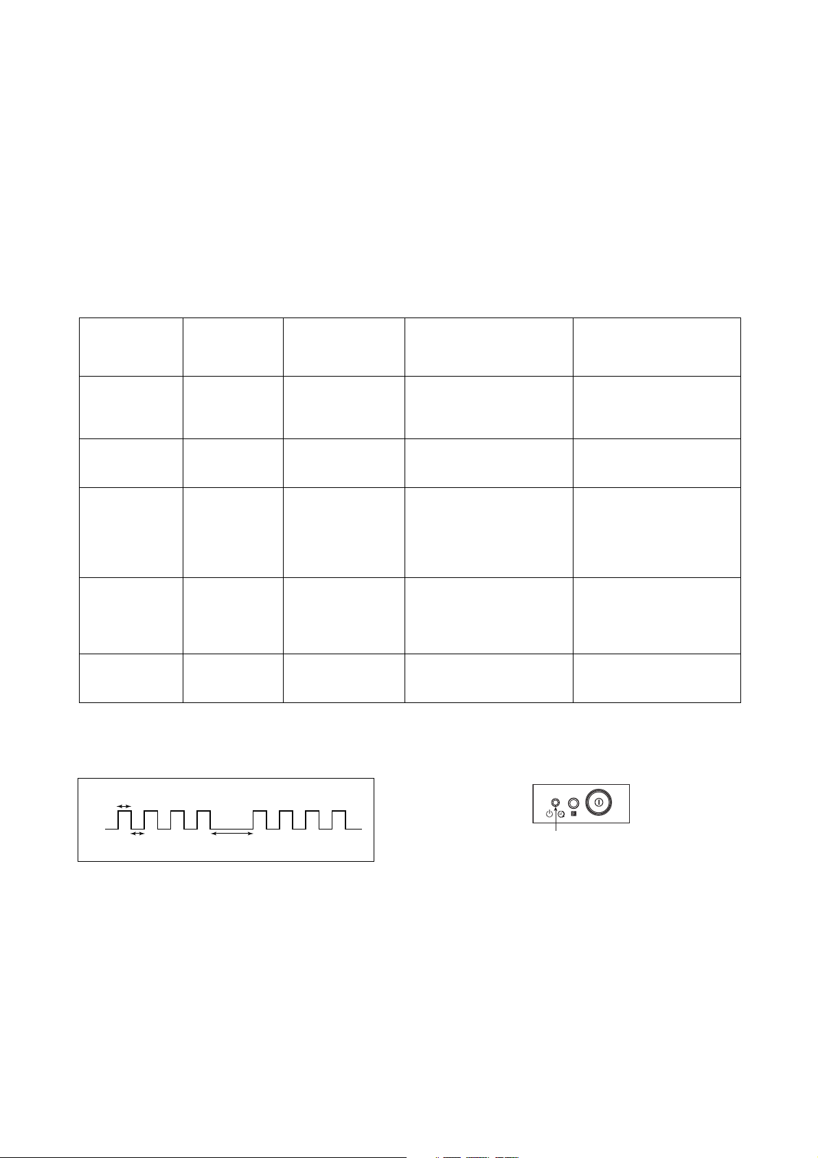
2. STANDBY INDICATOR BLINKING PROCESS
Lamp ON 300ms
Lamp OFF 300ms
The example above represents for 4 times blink
Lamp OFF 3 seconds
3. STANDBY INDICATOR ON TV FRONT PANEL
Standby indicator
– 3 –
KV-SW21M20/M80/M95
RM-GA002
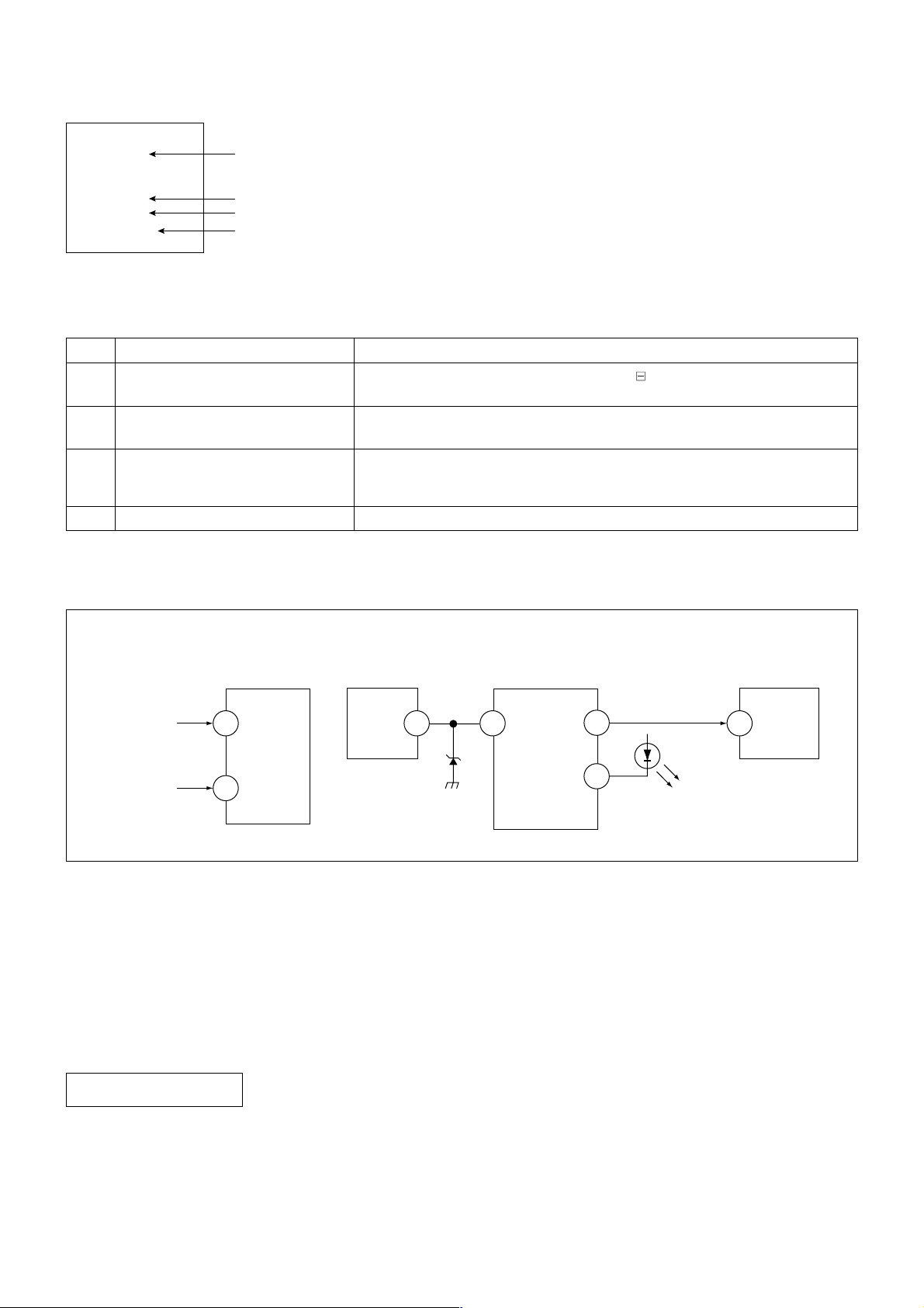
4. SELF DIAGNOSTIC SCREEN DISPLAY
SELF DIAGNOSTIC
2 : 000
3 : 000
4 : 000
5 : 001
8 : 002
101 : N/A
5. HANDLING SELF DIAGNOSTIC SCREEN DISPLAY
No. Description Method
1. Display self diagnostic screen [Display] t [Channel ] t [Volume ] t [Power / TV]
2. Stop standby flash i) Turn off power switch on main.
3. Clear fault result [Channel ] t -
4. Quit self diagnostic screen Turn off power switch of remote commander or main unit.
"0" means no fault has been detected.
"1" means a fault has been detected.
"2" means two faults have been detected.
"N/A" means not available for this models.
5
Note: The above must be performed while TV is on standby mode.
ii) Unplug power cord from the outlet.
8
Note: Diagnostic results display on screen is not automatically cleared. Therefore,
clear result after completion of repair.
6. SELF-DIAGNOSTIC CIRCUIT
FROM
C BOARD
IC751 PIN 5
A BOARD
FROM
Q816
COLLECTOR
A BOARD
IC001
Y/CHROMA JUNGLE
IK
32
EHTO
A BOARD
IC804
V.OUT
F.B-PLS
A BOARD
IC001
SYSTEM
SDA1
3 1384
V.GUARD
RED LED
99
122
DISPLAY
A BOARD
IC003
MEMORY
5
SDA
[+B overcurrent $OCP%] Occurs when an overcurrent on the +B(135V) line is detected by pin 32 of IC001 (A board).
If the voltage of pin 32 of IC001 (A board) is more than 4V, the unit will automatically go to
standby.
[V-PROTECT] Occurs when an absence of the vertical deflection pulse is detected by pin 13 of IC001
(A board).
[IK $AKB%] If the RGB levels* do not balance within 15 sec after the power is turned on, this error will be
detected by IC001 (A board). TV will stay on, but there will be 5 times LED blinking.
POWER SUPPLY NG (+5V)
for VIDEO PROCESSOR
Occurs when IC001 internal HV protect detects an abnormal H-Pulse (frequency) due to
improper power supply to IC001. TV cuts off high voltage power of anode CRT. No picture will be
detected. eg: IC602, IC604 go faulty.
* (Refers to the RGB levels of the AKB detection Ref pulse that detects IK.)
– 4 –
SECTION 1
DISASSEMBLY
KV-SW21M20/M80/M95
RM-GA002
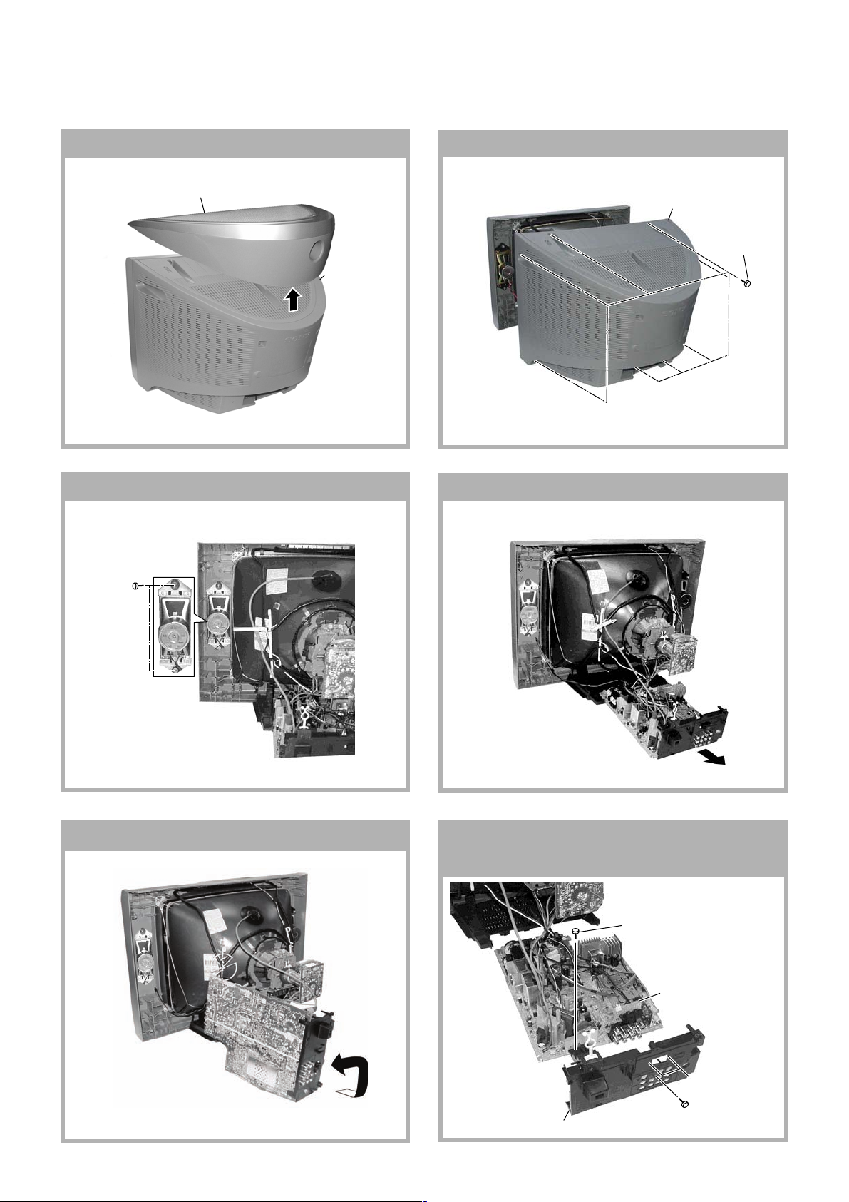
1-1 3D BOX REMOVAL (KV-SW21M95)
1
3D Speaker box assy
2
1-3. SPEAKER REMOVAL
1
Two screws
(Washer Head)
(+P4 x16)
Rear cover
1-2 REAR COVER REMOVAL
1-4. CHASSIS ASSY REMOVAL
2 Rear cover
Eight screws
1
(+BVTP 4
× 16)
1-5. SERVICE POSITION
– 5 –
1-6. TERMINAL BRACKET AND
J BOARD REMOVAL
1
One screw
(+
BVTP 3
5
(
One screw
2
+BVTP
3
Terminal bracket
(
× 12)
J Board
KV-SW21M95
Two screws
4
+BVTP
(
16
×
4
)
)
12
×
3
)

KV-SW21M20/M80/M95
RM-GA002
1-7. A BOARD REMOVAL
A Board
1-8. PICTURE TUBE REMOVAL
Note:
• The picture tube is upside down for (KV-SW21M20(South Africa)) only and the position for the anode cap and tension
springs are changed accordingly.
• Please make sure the TV set is not in standing position before removing necessary CRT support located on bottom right
and left.
1) Remove the Rear Cover.
2) Unplug all interconnecting leads from the Deflection Yoke, Neck Assy, Degaussing Coils and CRT grounding strap.
Remove Chassis Assy.
3) Place the TV set with the CRT face down on a cushion (jig).
4
Anode Cap Removal
7
Degaussing Coil
6
Loosen the Neck Assembly
fixing screw and remove
Neck Assy & VM board
5
C Board Removal
0
Earth Coating Assy
8
Holder, DGC
Removal (x2)
qd
Screw, Tapping 5 + Crown Washer (x4)
9
Spring Tension
Removal (x2)
qs
Supports, CRT
Removal (x2)
qa
Loosen the Deflection Yoke
fixing screw and remove
– 6 –
KV-SW21M20/M80/M95
RM-GA002
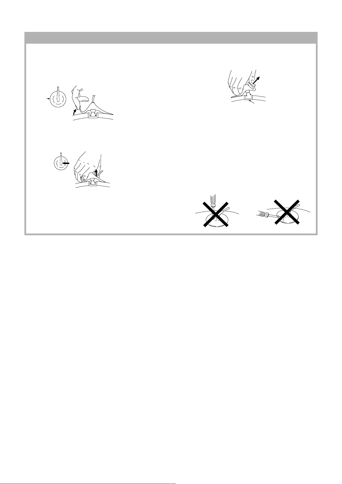
• REMOVAL OF ANODE-CAP
Note:
• After removing the anode, short circuit the anode of the picture tube and the anode cap to the metal chassis, CRT shield or
carbon paint on the CRT.
• REMOVING PROCEDURES
A
A
1 Turn up one side of the rubber cap in the direction
indicated by the arrow a.
B
B
2 Using a thumb pull up the rubber cap firmly in the direction
indicated by the arrow b.
C
Anode Button
3 When one side of the rubber cap is separated from the
anode button, the anode-cap can be removed by turning
up the rubber cap and pulling it up in the direction of the
arrow c.
• HOW TO HANDLE AN ANODE-CAP
1 Do not damage the surface of anode-caps with sharp
shaped objects.
2 Do not press the rubber too hard so as not to damage
the inside of anode-cap.
A metal fitting called the shatter-hook terminal is built
into the rubber.
3 Do not turn the foot of rubber over too hard.
The shatter-hook terminal will stick out or damage the
rubber.
– 7 –
KV-SW21M20/M80/M95
RM-GA002
SECTION 2
SET-UP ADJUSTMENTS
The following adjustments should be made when a complete
realignment is required or a new picture tube is installed.
Perform the adjustments in order as follows:
1. Beam Landing
2. Convergence
The controls and switch should be set as follows unless
otherwise noted:
3. Focus
4. G2 (SCREEN)
5. White Balance
Picture control ......................................................... NORMAL
Brightness control ................................................... NORMAL
Note: Test Equipment Required
1. Pattern Generator
2. Degausser
3. DC Power Supply
5. Oscilloscope
6. Landing Checker
7. XCV Adjuster
4. Digital Multimeter
.................................................................................................................................................................................................................................
Preparation :
• Feed in the white pattern signal.
• Before starting, degauss the entire screen with the
degausser.
• In order to reduce the geomagnetism on the set's
picture tube, face it east or west.
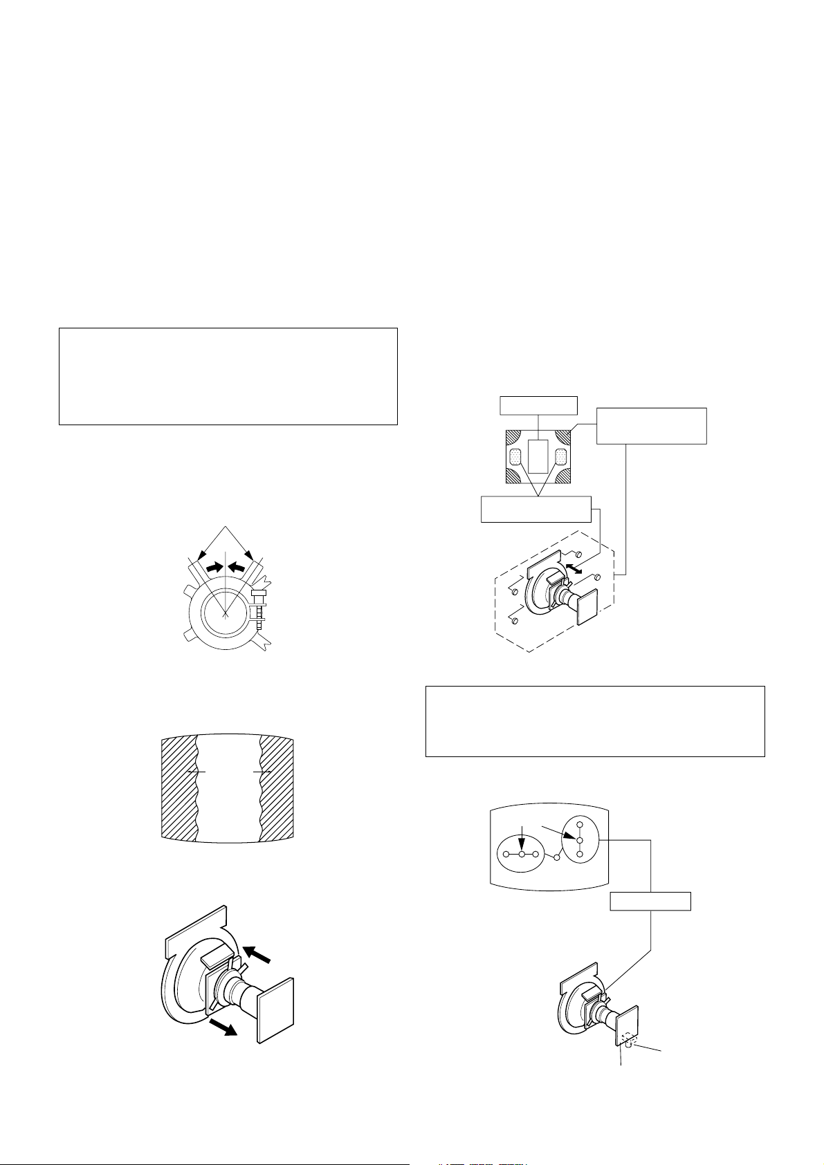
2-1. BEAM LANDING ADJUSTMENT
1. Input a raster signal with the pattern generator.
7. When the position of the DY is determined, tighten it
with the DY mounting screw.
8. If the beam does not land correctly in all corners of the
screen, use magnet disc to correct it.
Purity control
corrects this area.
a
b
d
c
Disc magnets or rotatable
disc magnets correct these
areas (a-d).
2. Loosen the deflection yoke mounting screw, and set the
purity control to the center as shown below.
Purity control
Deflection yoke positioning
corrects these areas.
3. Set the raster signal of the pattern generator to green.
4. Move the deflection yoke (DY) backward and adjust the
purity control so that green is in the center and blue and
red are at the sides evenly.
Blue
Red
Green
5. Then move the DY forward and adjust so that the entire
screen becomes green.
b
c
a
d
2-2. CONVERGENCE ADJUSTMENT
Preparation :
• Before starting, perform FOCUS adjustment.
• Picture mode STANDARD.
• Receive dot/cross hatch pattern.
a) Vertical Static Convergence
Center dot
R G B
R
G
B
4 pole magnet
6. Now switch over raster signal to red then blue and
confirm the condition.
RV750
H. STAT
C/CV Board
– 8 –
KV-SW21M20/M80/M95
ba
cd
a-d : screen-corner
misconvergence
RM-GA002
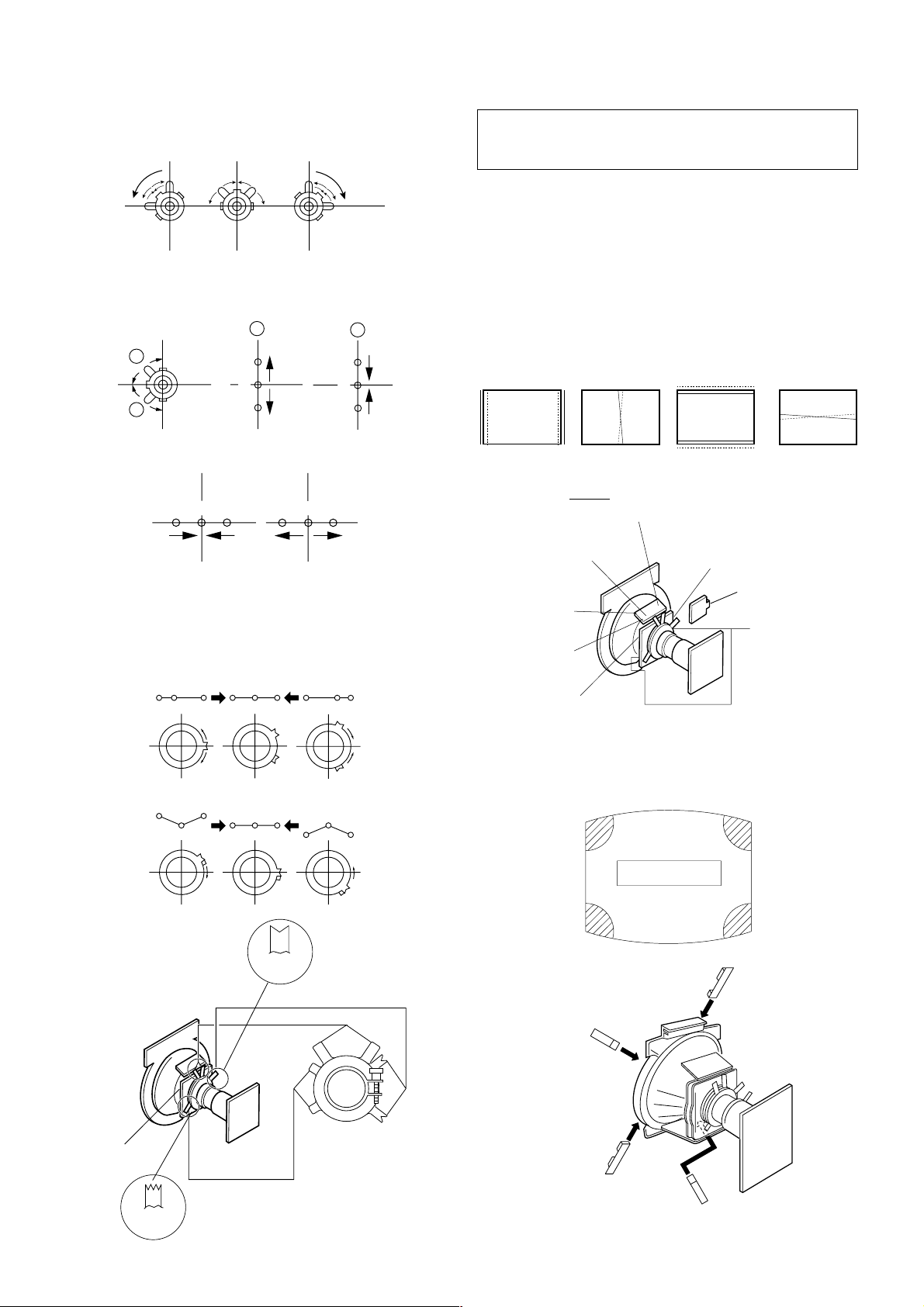
1. (Moving vertically), adjust the 4 pole magnet to converge
red, green and blue dots in the center of the screen.
2. Tilt the 4 pole magnet and adjust static convergence to
open or close the 4 pole magnet.
3. When the 4 pole magnet is moved in the direction of
arrow A and B, the red, green and blue dots moves as
shown below:
A
B
A
B
G
R
B
B
G
R
Moved RV750 (H.STAT)
RGGRB
B
c) Convergence Rough Adjustment
Preparation :
• Before starting this adjustment, adjust the horizontal
and vertical static convergence.
Input cross hatch pattern.
i) TLH
Adjust the horizontal convergence of red and blue dots
by inserting TLH Correction Plate to the DY pocket (left
or right).
ii) YCH
Adjust YCH to balance Y axis.
iii) TLV
Adjust the vertical convergence of red and blue dots.
iv) XCV
Adjust XCV to balance X-axis.
ON DY:
RB
YCH
TLV
B
R
R
B
TLV
B
R
TLH
XCV
b) Horizontal Static Convergence
If the blue dots does not converge with the red and green
dots, use the 6 pole magnet to adjust in the manner
described below.
RG B R G B R GB
RB
G
RG
6 Pole
Magnet
6 Pole Magnet
Purity
GB
RB
YCH
TLV
XCV
DY pocket
DY pocket
TLH Plate
XCV
d) Screen Corner Convergence
Affix a Piece A (90), Convergence Correct/Permaloy Assy
Correction to the misconverged areas.
b1
a1
DY pocket
4 Pole Magnet
4 Pole
Magnet
– 9 –
a1~d1:Piece A (90), Convergence Correct
Permaloy Assy Correction
d1
or
c1
KV-SW21M20/M80/M95
RM-GA002
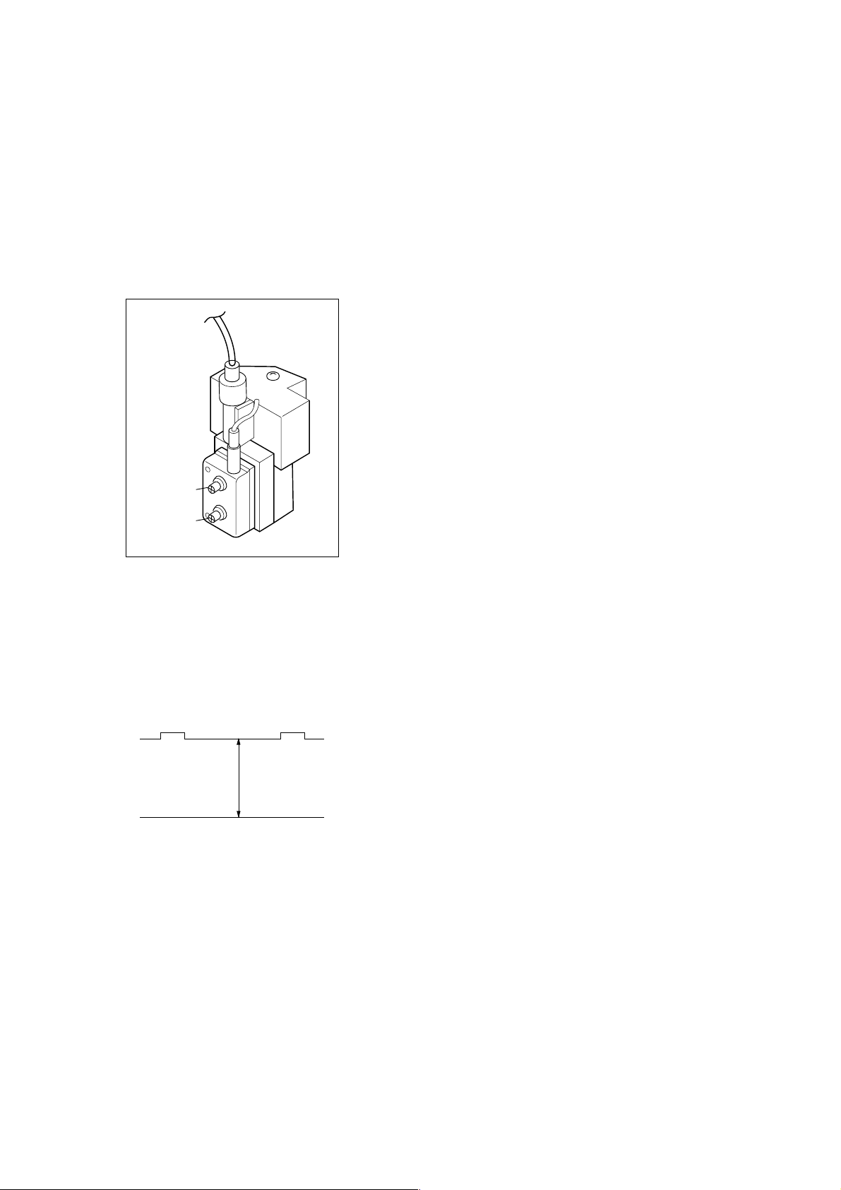
2-3. FOCUS ADJUSTMENT
FOCUS adjustment should be completed before W/B
adjustment.
1. Receive digital monoscope pattern.
2. Set Picture Mode to "DYNAMIC".
3. Adjust focus VR to obtain a just focus at the center of
the screen.
4. Change the receiving signal to white pattern and blue
back.
5. Confirm magenta ring is not noticeable. In case magenta
ring is obvious, then adjust FOCUS VR to balance
magenta ring and FOCUS.
FOCUS
2-5. WHITE BALANCE ADJUSTMENT
1. Set to Service Mode.
2. Input white raster signal using signal generator.
3. Set the following condition:
Picture "DYNAMIC", PICT 006 "WTS" to 00.
4. At Highlight condition, select WHBL 003 "GDRV" and
004 "BDRV" with 1 and 4 button of the remote
commander then adjust the data with 3 and 6 button.
5. At Cutoff, select WHBL 000 "BKOR" and 001 "BKOG"
and adjust the data.
6. Perform adjustment at Highlight and Cutoff condition
until it reaches its target.
7. Write data into memory by pressing [MUTING] t -.
8. Finally set PICT 006 "WTS" back to its original data.
SCREEN
2-4. G2 (SCREEN) ADJUSTMENT
1. Set the following condition:
– Picture and Brightness to "STANDARD".
– TV to Video mode.
– WHBL 016 "RGBB" to 01
2. Connect R, G, B of the C/CV board cathode to
oscilloscope.
3. Adjust Brightness to obtain the cathode value to the
value stated below.
165 ± 2VDC
4. Adjust SCREEN VR on the FBT until the scanning line
disappears.
5. Finally set WHBL 016 "RGBB" back to 00.
– 10 –
SECTION 3
CIRCUIT ADJUSTMENTS
3-1. ADJUSTMENTS WITH COMMANDER
Service adjustments to this model can be performed using the supplied remote commander RM-GA002.
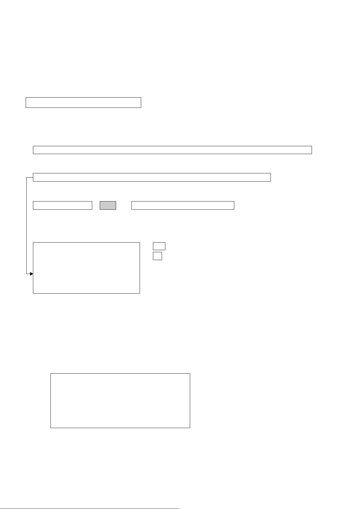
a. ENTERING SERVICE MODE
With the unit on standby
t [DISPLAY] t 5 t [VOL $+% ] t [POWER]
This operation sequence puts the unit into service mode.
This screen display is:
KV-SW21M20/M80/M95
RM-GA002
category in decimal item name in decimal NG service command frequency video input name
GEOM 006 HSIZ 031 x SERVICE 60 S VIDEO 1
release ID version in binary for factory color system (decimal)
SUS01 0.69U 0001 1111 FF FF NTSC3 65535
111 11 11 1 7 11 FG xy 111 000000 000000
S : for Sony
A : Aiwa
U S : US/Latin/Taiwan
E U : Europe
G A : General Area
J P : Japan
item no. service data NVM field channel no./
software service data reserved power on time
Status Byte Status Byte
Flash DCXO #1 SSD #2 SSD
VDSP_C Flag
CO_LOCKED
VDSP
Detected Stereo Type (Direct Value from CZ_ Stereo_Mode)
111 Needed for Nicam DCXO aligment Purpose
xy Value of x = 0 - Unknown, 1 - BTSC, 2 - A2, 3 - NICAM,
4 - KOREAN, 5 - Japan, 6 - AV Stereo
Value of y = 0 - Mono, 1 - Stereo, 2 - Bilingual, 4 - SAP/Single
0 1 : serial no. of the M/P release
for each destination
b. METHOD OF CANCELLATION FROM SERVICE MODE
Set the standby condition (Press [POWER] button on the commander), then press [POWER] button again, hereupon it becomes
TV mode.
c. METHOD OF WRITE INTO MEMORY
1. Set to Service Mode.
2. Press 1 (UP) and 4 (DOWN), to select the adjustment item.
3. Change item by pressing 3, 6.
4. Press [MUTING] button to indicate WRITE on the screen.
5. Press - button to write into memory.
1, 4 Select the adjustment item.
r
3, 6 Raise/lower the data value.
r
[MUTING] Writes.
r
- Executes the writing.
d. MEMORY WRITE CONFIRMATION METHOD
1. After adjustment, pull out the plug from AC outlet, and then plug into AC outlet again.
2. Turn the power switch ON and set to Service Mode.
3. Call the adjusted items again to confirm adjustments were made.
– 11 –
KV-SW21M20/M80/M95
RM-GA002
e. OTHER FUNCTION VIA REMOTE COMMANDER
7, - All the data becomes the values in memory.
8, - All user control goes to the standard state.
Display, - Service data initialization (Be sure not to use usually.)
2, 5 Select Device or Category
3-2. ADJUSTMENT METHOD
Item Number 000 HPOS
This explanation uses H POSITION as an example.
1. Select "000 HPOS" with the 1 and 4 buttons, or 2 and 5.
2. Raise/lower the data with the 3 and 6 buttons.
3. Select the optimum state. (The standard is IF for PAL reception.)
4. Write with the [MUTING] button. (The display changes to WRITE.)
5. Execute the writing with the - button. (The WRITE display will be changed to red color while excuting, and back to
SERVICE.)
Example on screen display :-
GREEN
GEOM 000 HPOS 039 SERVICE 50 VIDEO 1
Adjusted with 3 and 6 buttons.
GREEN
GEOM 000 HPOS 039 WRITE 50 VIDEO 1
write with [MUTING].
RED
GEOM 000 HPOS 039 WRITE 50 VIDEO 1
Write executed with -.
The WRITE display
then returns to green
SERVICE
Use the same method for all Items. Use 1 and 4 to select the adjustment item, use 3 and 6 to adjust, write with
[MUTING], then execute the write with -.
Note : 1. In [WRITE], the data for all items are written into memory together.
2. For adjustment items that have different standard data between 50Hz or 60Hz, be sure to use the respective input
signal after adjustment.
– 12 –
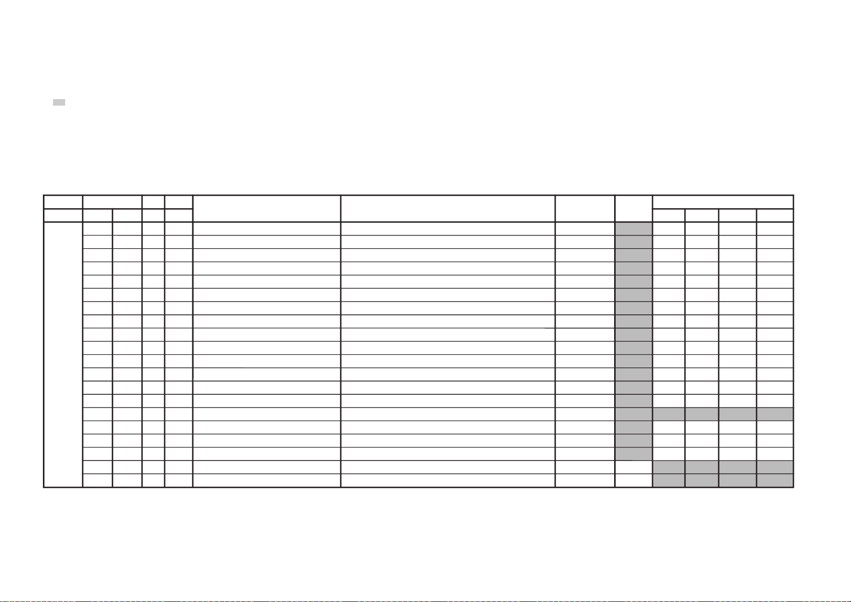
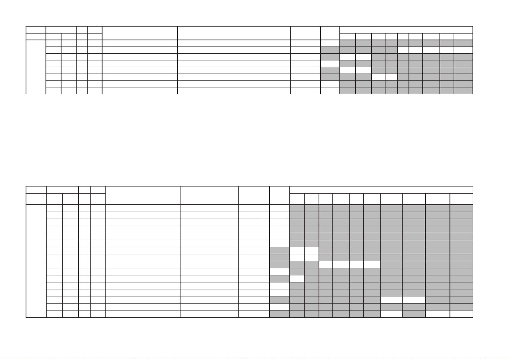
Adjustment Item Tabl e
JVTytilanoitcnuF.tinIegnaRnoitcnuFetoN&elbaTemaNeciveDnommoC)deliateD(eulaVlaitinI
yrogetaC.oNemaNceDceD 05)3:4(06)3:4(05w)3:4(06w)3:4(
MOEG000SOPH130360)SH(tfihSlatnoziroH >)Z/F/N/ZW(*)06/05(neercS9:61<>06w/05w/06/05neercS3:4< rossecorP-VT
13/0413/5413/2413/24
100RAPH130360margolellaraPlatnoziroH >)Z/F/N/ZW(*)06/05(neercS9:61<>06w/05w/06/05neercS3:4<
13131313
200WOBH130360woBlatnoziroH >)Z/F/N/ZW(*)06/05(neercS9:61<>06w/05w/06/05neercS3:4<
13131313
300NILV130360ytiraeniLlacitreV >)Z/F/N/ZW(*)06/05(neercS9:61<>06w/05w/06/05neercS3:4<
13131313
400RCSV130360llorcSlacitreV >)Z/F/N/ZW(*)06/05(neercS9:61<>06w/05w/06/05neercS3:4<
13131313
500ZISH130360)WE(htdiWWE >)Z/F/N/ZW(*)06/05(neercS9:61<>06w/05w/06/05neercS3:4<
13/6213/8213/5213/52
600WPWE130360)WP(htdiW/alobaraPWE >)Z/F/N/ZW(*)06/05(neercS9:61<>06w/05w/06/05neercS3:4<
13/42131313
700POCU710360alobaraPrenroCreppUWE >)Z/F/N/ZW(*)06/05(neercS9:61<>06w/05w/06/05neercS3:4<
71/1371/1371/1371/13
800POCL710360alobaraPrenroCrewoLWE >)Z/F/N/ZW(*)06/05(neercS9:61<>06w/05w/06/05neercS3:4<
71/1371/1371/1371/13
900ZTWE130360muizeparTWE >)Z/F/N/ZW(*)06/05(neercS9:61<>06w/05w/06/05neercS3:4< 13131313
010PLSV130360)SV(epolSlacitreV >)Z/F/N/ZW(*)06/05(neercS9:61<>06w/05w/06/05neercS3:4<
13131313
110ZISV510360edutilpmAlacitreV >)Z/F/N/ZW(*)06/05(neercS9:61<>06w/05w/06/05neercS3:4<
51/4251/625151
210ROCS410360)CS(noitcerroC-S >)Z/F/N/ZW(*)06/05(neercS9:61<>06w/05w/06/05neercS3:4<
41/5241/5241/5241/52
310SOPV130360)HSV(tfihSlacitreV >)Z/F/N/ZW(*)06/05(neercS9:61<>06w/05w/06/05neercS3:4<
13/9313/821313
410MOZV130360)ZV(mooZlacitreV >)Z/F/N/ZW(*)06/05(neercS9:61<>06w/05w/06/05neercS3:4<
510LBH000100edoMgniknalBBGR >)Z/F/N/ZW(*)06/05(neercS9:61<>06w/05w/06/05neercS3:4<
10101010
610FBW700510)FBW(gniknalBediWfognimiT >)Z/F/N/ZW(*)06/05(neercS9:61<>06w/05w/06/05neercS3:4<
70707070
710RBW700510)RBW(gniknalBediWfognimiT >)Z/F/N/ZW(*)06/05(neercS9:61<>06w/05w/06/05neercS3:4<
01010101
810LBS000100gniknalBecivreS >)Z/F/N/ZW(*)06/05(neercS9:61<>06w/05w/06/05neercS3:4< 00
910YPOC000100aeraMVNzH06/05llaotatadOEGehtypoC >)Z/F/N/ZW(*)06/05(neercS9:61<>06w/05w/06/05neercS3:4< 00/X
NOTE
a) In the initial value (detailed) column, the data after the slash mark ("/") refers to NTSC model data.
No ("/") means data is common for Multi and NTSC model.
b) Item remarked "*" and "**", please refer page 25 for the data.
c)
shaded items are no data.
d) Standard data listed on the Adjustment Item Table are reference values, therefore it may be different for each model and for each mode.
e) Note for the Different Data those are the standard data values written on the microprocessor. Therefore, the data values of the models are stored respectively in the memory.
In the case of a device replacement, adjustment by rewriting the data value is necessary for some items.
f) Multi ver 6.16, NTSC ver 6.16N.
– 13 –
KV-SW21M20/M80/M95
RM-GA002
KV-SW21M20/M80/M95
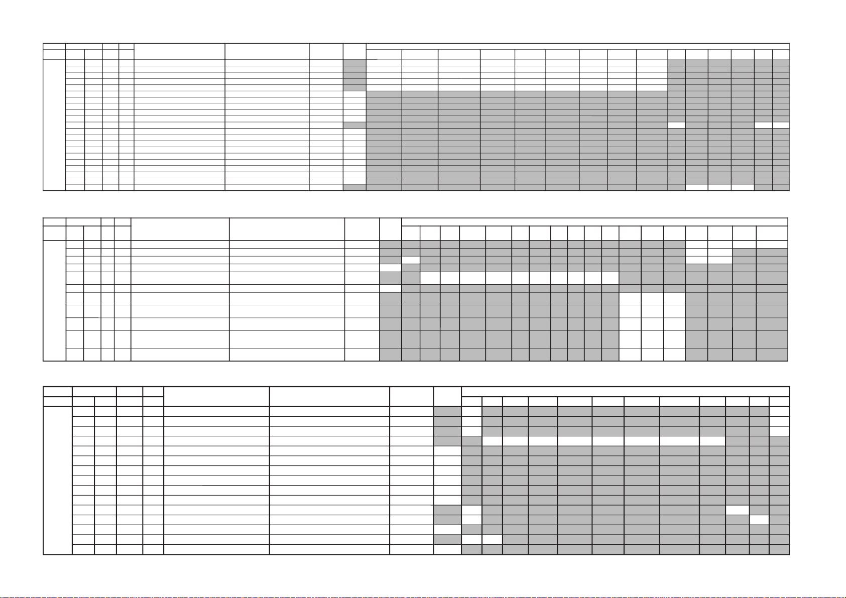
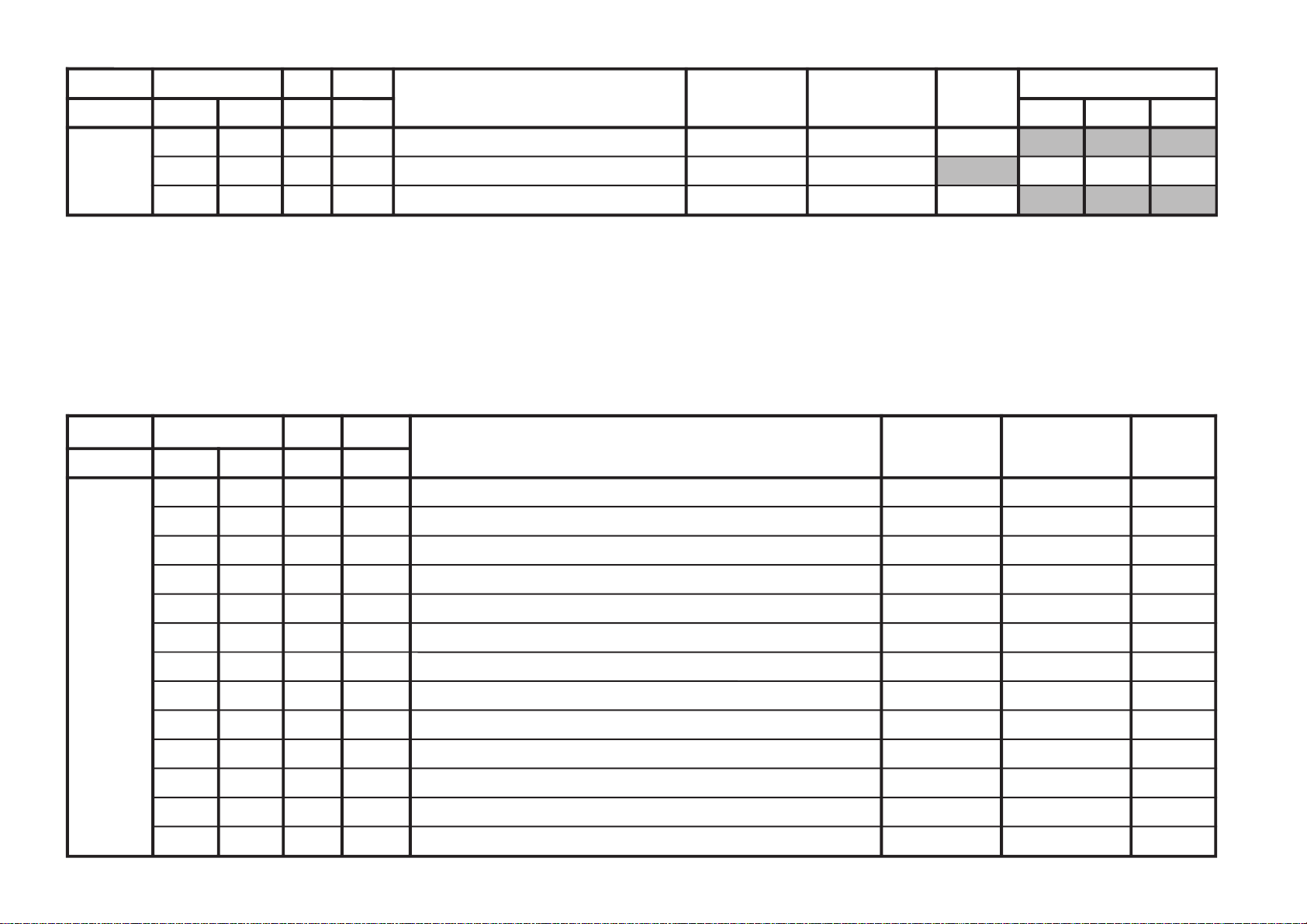
JVTytilanoitcnuF.tinIegnaRnoitcnuFetoN&elbaTemaNeciveDnommoC )deliateD(eulaVlaitinI
yrogetaC.oNemaNceDceD
VUYlap05
)VT(
lap05
)oediV(
maceS05
)VT(
maceS05
)oediV(
VT0606
)oediV(
VUY05VUY06BGR05BGR06edomciP
0
edomciP
1
edomciP
2
VToediV
ediWVT
)3:4(
ediWoediV
)3:4(
JDAS000XAMP360360mumixaMerutciP >ediW/lamroN</)ediW/lamroN(*)oediV/VT(rossecorP-VT
73737373
100EUHS700510euH-buS oediV/VT
7070
200PHSS510360ssenprahS-buS VUY/oediV/VT
53
84/3353
300OHSS000700)ciPtnegilletnI(tesffOssenprahS-buS enon60
400LOCS130360roloC-buS /)oediv(maces05/)vt(maces05/)oediv(lap05/)vt(lap05
BGR06/BGR05/VUY06/VUY05/oediv06/VT06
00/131300/1313131300/131300/1313
500OOCS000300)ciPtnegilletnI(tesffOroloC-buS enon20
600CIP130721;)dilavni(001>;)dilav(001~0:AG[lortnoCerutciP
])dilavni(6tiberongi;)dilav(36~0:srehtO
)ataDteseRresU=lanosreP:AG(ledoMerutciP
00108001
700LOC130721;)dilavni(001>;)dilav(001~0:AG[lortnoCroloC
])dilavni(6tiberongi;)dilav(36~0:srehtO
)ataDteseRresU=lanosreP:AG(ledoMerutciP
69/650505
800TRB130721;)dilavni(001>;)dilav(001~0:AG[lortnoCssenthgirB
])dilavni(6tiberongi;)dilav(36~0:srehtO
)ataDteseRresU=lanosreP:AG(ledoMerutciP
050505
900EUH130721;)dilavni(001>;)dilav(001~0:AG[lortnoCeuH
])dilavni(6tiberongi;)dilav(36~0:srehtO
)ledomSUhtiw)0-5(hE1#TNITotdneS*(
)ataDteseRresU=lanosreP:AG(ledoMerutciP
050505
010PHS130721;)dilavni(001>;)dilav(001~0:AG[lortnoCssenprahS
])dilavni(6tiberongi;)dilav(36~0:srehtO
)ataDteseRresU=lanosreP:AG(ledoMerutciP
060505
JVTytilanoitcnuF.tinIegnaRnoitcnuFetoN&elbaTemaNeciveDnommoC )deliateD(eulaVlaitinI
yrogetaC.oNemaNceDceD srehtOVUY)VT(LAP)VT(CSTN)VT(MACES)oediV(LAP)oediV(CSTN)oediV(MACESTUPNI-SMACESCSTNVT
CY000QRFP000300yaleDdnaycneuqerFretneCgnikaeP rehto/VTrossecorP-VT
00
00
100APR000300toohSrevO&erPoitaR rehto/VT
20
30/20
200OPR200300skaePevitageN&evitisoPfooitaR rehto/VT
20
10/20
300YLDY210510yaleD-Y TUPNI-S/VUY+)OEDIV/VT(*)MACES/CSTN/LAP(
9080/1150/808011901190
400TAMC000300xirtaM)ASU/napaJ(CSTNroMACES-LAP 00
500LCA100100gnitimiLroloCcitamotuA 10
600BC000100ycneuqerFretneCssapdnaBamorhC )xif0:oediV*(VThtiwylnodilav00/10
700OBS100300tesffOkcalBMACES 00
800ESHC100300ytivitisneStnedICSTN/LAP 20
900OLC000100retliF)lleB(ehcolCfoycneuqerFretneC 00
010PRTC000100edoMparTamorhC srehto/MACES
00
00/10
110SPB000100eniLyaleDdnab-esaBamorhCfossapyB srehto/CSTN
00
10
210OCF000100nOroloCdecroF 00
310TNIT130360lortnoCtniTdnaB-esaB srehto/VUY
1313
410VUT000100slangiSVUnolortnoCtniT 00
JVTytilanoitcnuF.tinIegnaRnoitcnuFetoN&elbaTemaNeciveDnommoC )deliateD(eulaVlaitinI
yrogetaC
pmeTloC
)rehtoLOOC(
pmeTloC
)rehtoMRAW(
pmeTloC
)rehtoLARTUEN(
pmeTloC
)VUYLOOC(
pmeTloC
)VUYMRAW(
pmeTloC
)VUYLARTUEN(
pmeTloC
)BGRLOOC(
pmeTloC
)BGRMRAW(
pmeTloC
)BGRLARTUEN(
VUY0edomciP1edomciP2edomciPVToediV
LBHW000ROKB130360)10=BFO(BtesffO,)00=BFO(RtesffOleveLkcalB )srehtO/BGR/VU(*)lamroN/WOL/HGIH(pmetlocrossecorP-VT
131313131313131313
100GOKB130360GtesffOleveLkcalB )srehtO/BGR/VU(*)lamroN/WOL/HGIH(pmetloc
131313131313131313
200VRDR730360RtnioPetihW )srehtO/BGR/VU(*)lamroN/WOL/HGIH(pmetlocrossecorP-VT
737373737373737373
300VRDG730360GtnioPetihW )srehtO/BGR/VU(*)lamroN/WOL/HGIH(pmetloc
73/1373/1373/1373/1373/1373/13-/13-/13-/13
400VRDB730360BtnioPetihW )srehtO/BGR/VU(*)lamroN/WOL/HGIH(pmetloc
73/1373/1373/1373/1373/1373/13-/13-/13-/13
500GPL000100teserPniaGBGR enon10
600RGP130721)RGP(RniaGteserP enon04
700GGP130721)GGP(GniaGteserP enon04
800BGP130721)BGP(BniaGteserP enon04
900FONG000510tesffOniaGteserP enonpoolCCC51
010TRBS130360ssenthgirB-buS VUY/BGR/srehtO
13
1313
110ORBS000300)ciPtnegilletnI(tesffOssenthgirB-buS enon00
210LGE000100metsySCCCnipooLniaGelbanE enon00
310LGS000300metsySCCCnitnerruChgiHfonoitceleS enon00
410BKA000100noitazilibatStnerruCkcalB enon00
510SBC000100gnitimiLtnerruCmaeBfoecneuqeSlortnoC enon00
610BBGR000300gniknalBBGR enon00
710GBLB000100tuptuOneerG&eulBfogniknalB enon00
810BFO000100eulBtesffOleveLkcalB enon10
910RBSN000510tesffOssenthgirBdradnatSnoN enon00
020PBW000300)woL:3,2,lamroN:1,hgiH:0(gnitteSpmeTroloC edoMerutciP
001010
RM-GA002
– 14 –
– 15 –
JVTytilanoitcnuF.tinIegnaRnoitcnuFetoN&elbaTemaNeciveDnommoC)deliateD(eulaVlaitinI
yrogetaC.oNemaNceDceD 05)3:4(06)3:4(srehtOVUYVToediVtxeteleTpi-VTlangisoN
CNYS000SYS000100tupnICNYSYnonoitazinorhcnyS rossecorPVT00
100OF000300tnatsnoCemiT1esahP )FR(langisoNrogninuTotuA/txeteleT/oediV/FFOPIVT/NOPIVT
303000/100000
200DIV000100edoMtnedIoediV 06/05
0000
300LSF000100cnySlacitreVrofleveLgnicilSdecroF 00
400LSS000100rotarapeScnySleveLgnicilS 06/05
0000
500DIVS100700noitacifitnedIoediVrofnoitceleSecruoS srehtO/VUY
0000
600FROF000300ycneuqerFdleiFdecroF 30
700KVM000100gniyeKnoisiVorcaM 10
JVTytilanoitcnuF.tinIegnaRnoitcnuFetoN&elbaTemaNeciveDnommoC )deliateD(eulaVlaitinI
yrogetaC.oNemaNceDceD
srehtOeviLVT
)nyD(
VT
)srehtO(
oediV
)nyD(
oediV
)srehtO(
pmeTroloC
)HGIH(
pmeTroloC
)srehtO(
roloC
)WOL(pmeT
pmeTroloC
)LAMRON(
TCIP000LDAC700510leveLevirDedohtaC 00
100AFC000300edoMretliFbmoC 00
200COS200300leveLgnippilCtfoS 00
300LWP100100hctiwSgnitimiLetihWkaeP 10
400LTHW600510gnitimiLetihWkaeP 00
500MAG100100ammaG 00
600STW100300hctertSetihWdnalortnoCammaGsrehtO/eviL
2020
700RFT000100langiSecnanimuLfooitaRrefsnarTCDsrehtO/eviL
1010
800ROC300300gniroC )srehto/anyD(*)oediV/VT(
00000000
900OROC000300)ciPtnegilletnI(tesffOgniroC 20
010SKB300300hctertSkcalBsrehto/BGR
20
110SAA100100hctertSkcalBehtffohctiwSotaerAkcalB 10
210KSD000100lortnoCnikScimanyD 00
310SLB000100hctertSeulB )SREHTO/HGIH(pmetloc
0000
410SLBN000100tiucriChctertSeulBnoitarepO 00
510RRN000100noitcudeRdeRnoN )LAMRON/WOL/HGIH(pmetloc
10
1010
KV-SW21M20/M80/M95
RM-GA002
KV-SW21M20/M80/M95
JVTytilanoitcnuF
laitinI
egnaR
noitcnuFetoN&elbaTemaNeciveDnommoC
yrogetaC.oNemaNceDceD
FIV000DFIO630360rotaludomeDFItesffO rossecorP-VT63
100TCGA130360revo-ekaTCGA 13
200MTS000100edoMgninuThcraeS 10
300DG000100langiS1SBVCnoyaleDpuorG 00
400SCGA100300deepSCGAFI 10
500IFF000100LLPFIretliFtsaF 00
600IANL000100eulavlaitinitibANLpmAFR 00
700TANL591522leveLdlohserhTpmAFR 591
800NSNL400700dlohserhTleveLNSpmAFR 30
900DSNL200700dlohserhTporDleveLNSpmAFR 10
010XENL610360gnimiTporDNSkcehcpmAFR 03
110RTHC840721edoMresUpmAFRtesotgrPotuAretfadlohserhTlennahC 52
210OSUT000100desUrenuTynoS 10/00
JVTytilanoitcnuF.tinIegnaRnoitcnuFetoN&elbaTemaNeciveDnommoC)deliateD(eulaVlaitinI
yrogetaC.oNemaNceDceD VUYoediVVT
WS0002VC000100noitceleSlangiStupnI2SBVC 00
100OVS10030084@niPISBVC/OVS/OVFIfonoitcnuFVUY/oediV/VT
201010
200LFD000100noitcetorPhsalF 10
RM-GA002
– 16 –
– 17 –
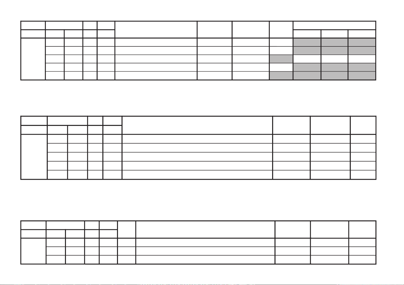
JVTytilanoitcnuF.tinIegnaRnoitcnuFetoN&elbaTemaNeciveDnommoC
yrogetaC.oNemaNceDceD
MEDS000SWMF000300rotaludomeDMFrofnoitceleSwodniW rossecorP-VT20
100SSQ100100 )metsysMitlumAGrofA/N(edoMreifilpmA)SSQ(dnuoStilpSisauQ *
200BPB000100retliFssapdnaBdnuoSfossapyB 00
300OLMA000100dnuoSMAroflangiStuptuOoiduA 00
400CVPH000100lortnoCemuloVenohPdaeH 00
JVTytilanoitcnuF.tinIegnaRataDnoitcnuFetoN&elbaTemaNeciveDnommoC
yrogetaC.oNemaNceDceD
TXT000VXT930360XIFspilihProfnoitisoPlacitreVtxeteleT redoceDtxeT00/93
100DHT010721XIFtfihSegdEevitcAcnys-HtxeteleT 00/01
200RBT510130XIFssenthgirBBGRtxeteleT 00/41
JVTytilanoitcnuF.tinIegnaRnoitcnuFetoN&elbaTemaNeciveDnommoC)deliateD(eulaVlaitinI
yrogetaC.oNemaNceDceD 0edomciP1edomciP2edomciP
MV000DBGR300700tuptuOMVottuptuOBGRfoyaleDenonrossecorP-VT40
100AMV300300tuptuOMVfoedutilpmAenon00
200PAMV200300)FFO:3,2,woL:1,hgiH:0(gnittesMVedoMerutciP
001000
300OMMV300300edoMMV 10
400AMVF400400)erawtfoSlluF(tuptuOMVfoedutilpmAsrehto/MACES
KV-SW21M20/M80/M95
RM-GA002
– 18 –
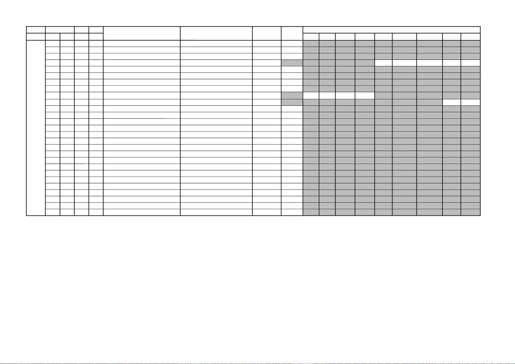
JVTytilanoitcnuF.tinIegnaRnoitcnuFetoN&elbaTemaNeciveDnommoC )deliateD(eulaVlaitinI
yrogetaC.oNemaNceDceD VToediVbuSFRbuSoediV
ffOWOW/SRSdnuorrusurToeretsIonomI
PSDS000LBB000510ruotnoCEBB DSS00
100HBB000510ssecorPEBB 00
200WLBB000510tesffOruotnoCEBB 60
300FOVS000510tesffOemuloVedoMtceffE/dnuorruS onomI/oeretsI/dnuorrusurT/)WOW/SRS(ffO
4011406040
400DAL000130tsujdAleveLredoceD 50
500MAL000130tsujdAleveLonoM 50
600NAL000130tsujdAleveLmaciN *
700SAL000130tsujdAleveLPAS 50/80
800AAL000130tsujdAleveLCDA buSoediV/buSFR/kpSretnec/oediV/FR
0000-/00-/00
900FES300700tceffEoeretS/onoMelbidercnI onomI/oeretsI
5030
010SAB000510tesffOssaBniaM *
110ERT000510tesffOelberTniaM *
2101QE000510tesffO)zH001(dnaBlennahCniaMrezilauqE *
3102QE000510tesffO)zH003(dnaBlennahCniaMrezilauqE *
4103QE000510tesffO)zH0001(dnaBlennahCniaMrezilauqE 00
5104QE000510tesffO)zH0003(dnaBlennahCniaMrezilauqE *
6105QE000510tesffO)zH0008(dnaBlennahCniaMrezilauqE *
710TCFB500700lortnoCEBBdnaBUD,EBD 00
810NECS100510lortnoCretneCD3SRS 40
910APSS000510lortnoCecapSD3SRS 10
020WHBB000510edomWOWnitesffossecorpEBB 00
120ERTS200700edomdnuorrusroftesffOelberT 10
220THBB000510edomVTnitesffOEBB 00
320ERTT200700edomVTnitesffOelberT 20
420SABV000300emulovresunodnepedtesffOssaB 00
520ERTV000300emanresunodnepedtesffOelberT 00
620SABT200700VTroftesffOssaB 00
KV-SW21M20/M80/M95
RM-GA002
 Loading...