

Sony KV-PG14N70 Service Manual
REVISION HISTORY
BG2T
CHASSIS
MODEL
KV-PG14N70
NO. SUFFIX DATE SUPPL. / CORR DESCRIPTION
1 -01 2001/11 -- 1st. Issue
PA RT NO. : 9-872-275-01
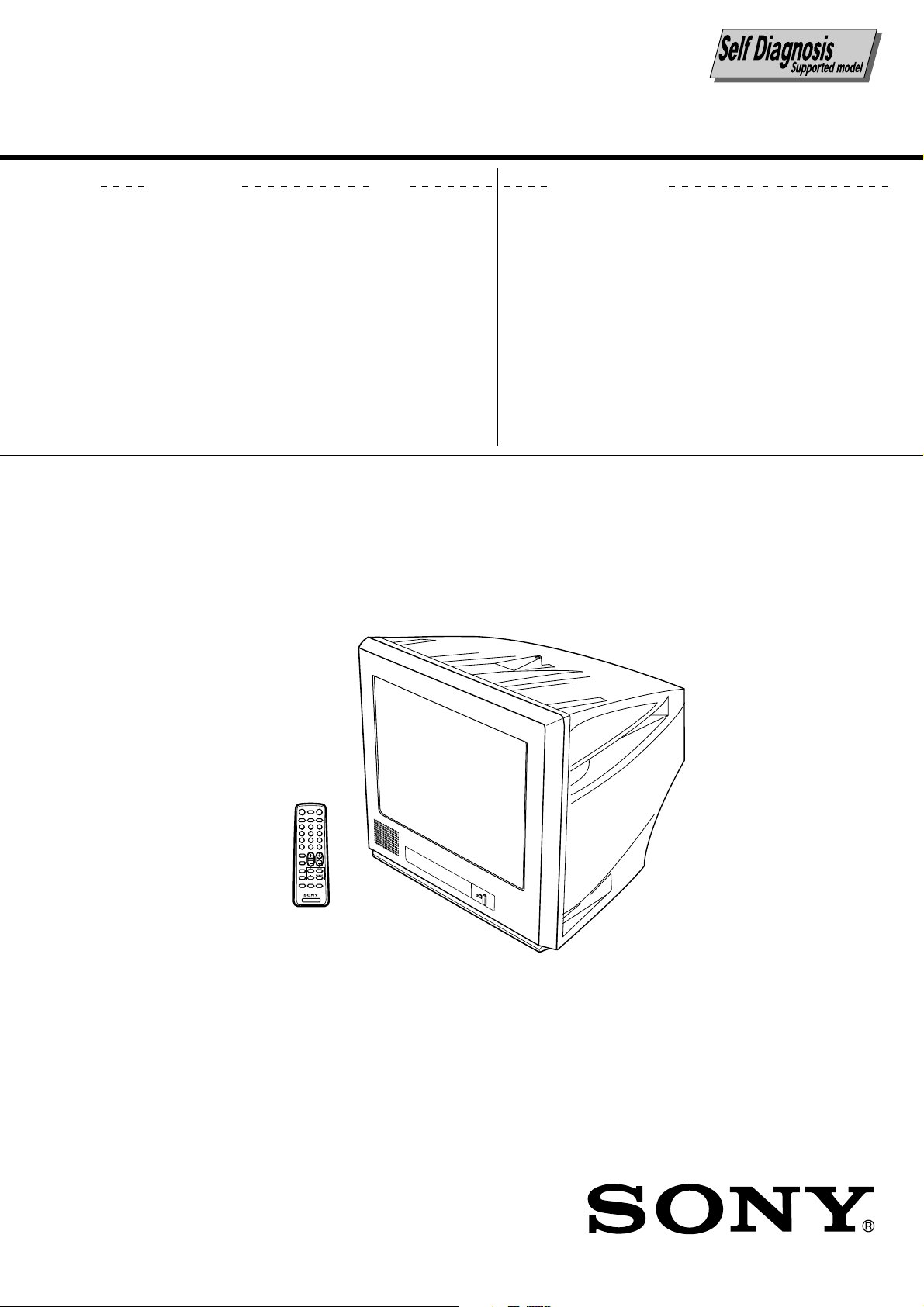
SERVICE MANUAL
BG2T
CHASSIS
MODEL COMMANDER DEST. CHASSIS NO.
KV-PG14N70 RM-915 Taiwan SCC-U77B-A
MODEL COMMANDER DEST. CHASSIS NO.
DISPLAYMUTING POWER
TV
MTS
VIDEO
3
1
2
6
4
5
9
7
8
JUMP
ENT
0
VOL CH
SOUND
MODE
FAVORITE
WAKE UP
SLEEP
AUTO
ADD/
CABLE
PROGRAM
ERASE
TV
TRINITRON
®
COLOR TV
KV-PG14N70
RM-915
Power requirements 110 V AC, 60 Hz
Power consumption (W) Indicated on the rear of the TV
Television system M
Color system PAL*, PAL 60*, NTSC3.58, NTSC4.43* *AV IN only
Channel coverage VHF: 2 to 13
˘(Antenna) 75-ohm external terminal
Audio output (Speaker) 3W
Number of terminal
VIDEO Input: 2* Output: 1 Phono jacks; 1 Vp-p, 75 ohms *One input line available
AUDIO Input: 2* Output: 1 Phono jacks; 500 mVrms *One input line available
@ (Earphone) Output: 1 Monaural minijack
Picture tube 14 in
Tube size (cm) 37 Measured diagonally
Screen size (cm) 34 Measured diagonally
Dimension (w/h/d,mm) 375 x 346 x 411
Mass (kg) 12
SPECIFICATIONS
Note
UHF: 14 to 69
CATV: 1 to 125
Design and specifications are subject to change without notice.
CAUTION
SHORT CIRCUIT THE ANODE OF THE PICTURE TUBE AND
THE ANODE CAP TO THE METAL CHASSIS, CRT SHIELD,
OR CARBON PAINTED ON THE CRT, AFTER REMOVING THE
ANODE.
SAFETY-RELATED COMPONENT WARNING!!
COMPONENTS IDENTIFIED BY SHADING AND MARK ! ON
THE SCHEMATIC DIAGRAMS, EXPLODED VIEWS AND IN
THE PARTS LIST ARE CRITICAL TO SAFE OPERATION.
REPLACE THESE COMPONENTS WITH SONY PARTS
WHOSE PART NUMBERS APPEAR AS SHOWN IN THIS
MANUAL OR IN SUPPLEMENTS PUBLISHED BY SONY.
– 2 –

TABLE OF CONTENTS
KV-PG14N70
RM-915
Section Title Page
SELF DIAGNOSTIC FUNCTION ................................... 4
1. GENERAL ................................................................. 7
2. DISASSEMBLY
2-1. Rear Cover Removal ............................................... 10
2-2. Speaker Removal .................................................... 10
2-3. Chassis Assy Removal ............................................ 10
2-4. F Board Removal .................................................... 10
2-5. Service Position ...................................................... 10
2-6. Terminal Bracket Removal ..................................... 10
2-7. Replacement Of Parts ............................................. 11
2-7-1. Replacement Of Light Guide ....................... 11
2-7-2. Replacement Of Power Button .................... 11
2-8. Picture Tube Removal ............................................. 11
3. SET-UP ADJUSTMENTS
3-1. Beam Landing ......................................................... 13
3-2. Convergence ............................................................ 14
3-3. Focus Adjustment.................................................... 16
3-4. G2 (SCREEN) and White Balance Adjustments ... 16
Section Title Page
5. DIAGRAMS
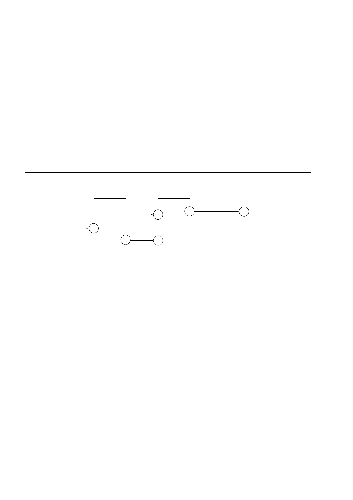
5-1. Block Diagram ........................................................ 25
5-2. Circuit Boards Location .......................................... 27
5-3. Schematic Diagram ................................................. 28
(1) A Board Schematic Diagram ............................ 29
(2) C and F Boards Schematic Diagram................. 31
5-4. Voltage Measurement ............................................. 33
5-5. Waveforms .............................................................. 35
5-6. Printed Wiring Boards and Parts Location ............. 36
5-7. Semiconductors ....................................................... 39
6. EXPLODED VIEWS
6-1. Picture Tube and Chassis ........................................ 41
7. ELECTRICAL PARTS LIST.................................... 43
4. CIRCUIT ADJUSTMENTS
4-1. Adjustment With Commander ................................ 17
4-2. Adjustment Method ................................................ 17
4-3. Picture Quality Adjustment .................................... 23
4-4. Deflection Adjustment ............................................ 23
4-5. A Board Adjustment After IC003 (MEMORY)
Replacement ............................................................ 23
4-6. Picture Distortion Adjustment ................................ 24
– 3 –
KV-PG14N70
RM-915
SELF DIAGNOSTIC FUNCTION
The units in this manual contain a self-diagnostic function. If an error occurs, the STANDBY/TIMER lamp will automatically begin to flash.
The number of times the lamp flashes translates to a probable source of the problem. A definition of the STANDBY/
TIMER lamp flash indicators is listed in the instruction manual for the user’s knowledge and reference. If an error
symptom cannot be reproduced, the remote commander can be used to review the failure occurrence data stored in
memory to reveal past problems and how often these problems occur.
1. DIAGNOSTIC TEST INDICATORS
When an errors occurs, the STANDBY/TIMER lamp will flash a set number of times to indicate the possible cause of the
problem. If there is more than one error, the lamp will identify the first of the problem areas.
Result for all of the following diagnostic items are displayed on screen. No error has occured if the screen displays a “0”.
Diagnostic
Item
Description
• Power does not
turn on
• +B overcurrent
(OCP)
• Horizontal
deflection
overdrive
• White balance
failure (no
PICTURE)
• Vertical deflection
stopped
• Micro reset
No. of times
STANDBY/TIMER
lamp flashes
Does not light
2 times
4 times
—
Self-diagnostic
display/Diagnostic
result
—
002:000 or
002:001~255
004:000 or
004:001~225
101:00 or
101:001~225
Probable
Cause
Location
• Power cord is not
plugged in.
• Fuse is burned out
F4601 (F)
• H.OUT Q801 is shorted.
(A board)
• -13V is not supplied.
(A board)
• IC 551 faulty (A board)
• Discharge CRT
(C Board)
• Static discharge
• External noise
Detected
Symptoms
• Power does not come on.
• No power is supplied to
the TV.
• AC power supply is faulty.
• Power does not come on.
• Load on power line is
shorted.
• Has entered standby state
after horizontal raster.
• Power line is shorted or
power supply is stopped.
• Vertical deflection pulse
is stopped
• Power is shut down
shortly, after this return
back to normal.
• Detect Micro latch up.
Note 1: If a + B overcurrent is detected, stoppage of the vertical deflection is detected simultaneously.
The symptom that is diagnosed first by the microcontroller is displayed on the screen.
Note 2: Refer to screen (G2) Adjustment in section 3-4 of this manual.
– 4 –

2. DISPLAY OF STANDBY/TIMER LIGHT FLASH COUNT
2 times
KV-PG14N70
RM-915
Diagnostic Item Flash Count*
+B overcurrent/overvoltage 2 times
4 times
Lamp ON 0.3 sec.
Lamp OFF 0.3 sec.
Lamp OFF 3 sec.
Vertical deflection stopped 4 times
* One flash count is not used for self-diagnostic.
STANDBY/SLEEP lamp
3. STOPPING THE STANDBY/TIMER FLASH
Turn off the power switch on the TV main unit or unplug the power cord from the outlet to stop the STANDBY/TIMER
lamp from flashing.
4. SELF-DIAGNOSTIC SCREEN DISPLAY
For errors with symptoms such as “power sometimes shuts off” or “screen sometimes goes out” that cannot be confirmed, it is possible to bring up past occurances of failure for confirmation on the screen:
[To Bring Up Screen Test]
In standby mode, press buttons on the remote commander sequentially in rapid succession as shown below:
[Screendisplay] / channel [5] / Sound volume [-] / Power ON
˘
Note that this differs from entering the service mode (mode volume [+]).
Self-Diagnosis screen display
SELF DIAGNOSTIC
002 : 000
004 : 000
101 : 000
Numeral "0" means that no fault has been detected.
– 5 –
KV-PG14N70
RM-915
5. HANDLING OF SELF-DIAGNOSTIC SCREEN DISPLAY
Since the diagnostic results displayed on the screen are not automatically cleared, always check the self-diagnostic
screen during repairs. When you have completed the repairs, clear the result display to “0”.
Unless the result display is cleared to “0”, the self-diagnostic function will not be able to detect subsequent faults after
completion of the repairs.
[Clearing the result display]
To clear the result display to “0”, press buttons on the remote commander sequentially as shown below when the
diagnostic screen is being displayed.
Channel [8] / 0
[Quitting Self-diagnostic screen]
To quit the entire self-diagnostic screen, turn off the power switch on the remote commander or the main unit.
6. SELF-DIAGNOSTIC CIRCUIT
FROM
[+B] Q500
IC301
Y/CHROMA JUNGLE
MP/
50
PROTECT
8
SDA
[V]
D553
IC001
SYSTEM
II-DAT1 DAT
17
54
II-DATO
53
IC003
MEMORY
5
[+BovercurrentªOCPº] Occurs when an overcurrent on the +B(135) line is detected by Q500. If Q500 go to
ON and the voltage to pin 50 of IC301 more than 3.5V when V.SYNC is more than
seven verticals in a period, the unit will automatically turn off.
[Verticaldeflectionstopped] Occurs when an absence of the vertical deflection pulse is detected by Pin 17 and
IC001 shut down the power supply.
[Whitebalancefailure] If the RGB levels* do not balance or become low level within 5 seconds, this error
will be detected by IC301. TV will stay on, but there will be no picture.
* (Refers to the RGB levels of the AKB detection Ref pulse that detects IK.)
– 6 –
The operating instruction mentioned here are partial abstracts
from the Operating Instruction Manual. The page numbers of
the Operating Instruction Manual remain as in the manual.
KV -PG14N70
RM-915
SECTION 1 GENERAL
A 準備工作
b
b
!
CABLE
AUTO
PROGRAM
SELECT
步驟
1
將所提供的電池裝入遙控器。
注
• 請勿使用舊電池或同時使用不同類型的電池。
步驟
2
將天線電纜(未提供)連接至電視機背後的 8(天線輸
入)端子。
提示
• 您也可將本電視機連接至其它選購的裝置。(參考 E)
步驟
3
插入電源線﹐然後按壓電視機上的 !(電源)鍵以接通電
視機電源。
步驟
4
按壓電視機上的 CABLE(有線電視)鍵以選擇“有線電
視:開”﹐然後再按壓遙控器上的 AUTO PROGRAM(自
動頻道記憶)鍵以自動預設頻道。(參考 J)
提示
• 若要停止自動頻道預設﹐請按壓 SELECT(功能選擇)鍵。
步驟
5
按壓遙控器上的 SELECT
LANGUAGE : 中文”顯示於畫面上﹐然後按壓 + 或 –
鍵以改變畫面顯示語言。
(功能選擇)
鍵直到“語文顯示/
警告(續)
請勿在同一電源插座上插入太多的電器。請勿損壞
請勿放置任何物體於電視機上。
放置電視機於穩定的、並足以支撐電視機重量的電
視支架及地面上。確保電視支架的表面平整且表面
積寬放電視機底面。
C
固定電視機
電源線。
捏住插頭將電源線拔開。請勿直接拉拔電源線。既
使電視機已斷開電源﹐但只要電源線還在插座內﹐
它仍接通至交流電源。若想移動本電視機或打算近
期內不使用本電視機時﹐請將電源線拔開。
B 僅於 KV-PG21 (Not used for this model)
為防止電視機摔落﹐請使用所提供的螺釘、夾子和帶條以固定電視機。
20 毫米
3.8 毫米
螺釘 夾子 帶條
將帶條分別固定至電視機背後提供的螺絲
孔及電視支架上。
或
(1) 將一根繩索或鏈條穿過夾子。
(2) 將其中一個夾子固定至牆上或柱子上﹐
而另一個夾子則固定至電視機背後提
供的螺絲孔上。
B 警告
• 本電視機內存在危險性高電壓。
• 本電視機僅可在 110 伏特交流電壓下操作。
• 若未完成所有連接程序﹐請勿插入電源線﹔否則極少量的電流可能經天線或其它端子外泄。
• 若打算近期內不使用遙控器﹐請將電池取出﹐以避免電池泄漏而損壞遙控器。若您不小心觸及
電池所泄漏的液體﹐應立即用水洗淨。
為了個人安全起見﹐雷雨期間﹐請勿觸摸電視機的
任何部份﹐包括電源線和天線電纜。
為防止火災或觸電﹐請勿使本電視機被雨淋或受潮。若有任何液體流入或固體落入本電視機內時﹐請勿
請勿堵塞本電視機的通風口。
請勿將本電視機放置於諸如書架或嵌入式壁櫥等封
閉之處。
為了兒童安全起見﹐請勿讓他們獨自逗留在電視機
旁。千萬別讓兒童攀爬本電視機。
操作本電視機。應立即請合格的專業人員檢查。
請用乾的軟布清潔本電視機。請勿使用汽油、稀釋
劑或任何其它化學品清潔本電視機。請勿刮劃顯像
管。
注
• 請僅使用提供的螺釘。使用其它螺釘可能會損壞本電視機。
D 電視機前面和背後的控制板
電視機背後的控制板
0
AUDIO VIDEO
VIDEO
IN
MONITOR
OUT
電視機前面的控制板
SOUND
VIDEO
VIDEO INPUT
9
按鍵 功能
1 !(電源) 接通或切斷電視機電源。
2 遙控傳感器。
3 STANDBY(待機) 待機指示燈。
3 WAKE UP(開機定時) 開機定時指示燈。
4 CHANNEL +/–(頻道) 選擇頻道號碼。
5 VOLUME +/–(音量)* 調整音量。
6 TV/VIDEO(電視∕影音) 選擇電視或影音輸入。
7 SELECT(
功能選擇
8 耳機插口。
9 VIDEO INPUT(影音輸入) 影音輸入端子。
0 8 天線輸入端子。
qa VIDEO IN(影音輸入) 影音輸入端子。
qs MONITOR OUT(監視器輸出) 監視器輸出端子。
* 您也可使用電視機上的 VOLUME +/–(音量)鍵以取代遙控器上的 +/– 鍵進行操作。
) 選擇所要的項目。
SELECT
7
TV/
VIDEO
6
584
STANDBY/
!
WAKE UP
CHANNELVOLUME
1
3
2
qa
qs
請勿打開本電視機的機殼和後蓋﹐因電視機內存在
高電壓和危險性部件。須由合格的專業人員對電視
機進行檢修或棄置。
本電視機只適於家庭使用。請勿將本電視機放置於
任何交通工具內或多塵、高溫、潮濕或震動頻繁之
處。
– 7 –
KV -PG14N70
RM-915
E 連接選購的裝置
連接至影音輸入端子
電視機前面的控制板
SOUND
VIDEO
VIDEO INPUT
電視機背後的控制板
AUDIO VIDEO
VIDEO
IN
MONITOR
OUT
注
• 請不要把影像裝置同時連接至本電視機前面的 VIDEO INPUT(影音輸入)和背後的
VIDEO IN(影音輸入)。否則圖像將不能良好地在畫面上顯示。
連接至監視器輸出端子
電視機背後的控制板
AUDIO VIDEO
VIDEO
IN
MONITOR
OUT
聲音影像電纜
(未提供)
天線電纜
(未提供)
聲音影像電纜
(未提供)
聲音影像電纜
(未提供)
攝影機
電視遊戲機
錄影機
音響系統
H 遙控器
DISPLAYMUTING POWER
qa
qs
MTS
1
4
7
JUMP
SOUND
MODE
FAVORITE
WAKE UP
SLEEP
CABLE
VIDEO
2
5
8
0
VOL CH
AUTO
PROGRAM
TV
qd
qf
qg
qh
qj
qk
ql
w;
wa
ADD/
ERASE
TV
3
6
9
ENT
按鍵
1 POWER(電源)
1
2 TV(電視)
2
3 ENT
4 CH +/–(頻道)
5 VOL +/–(音量)
6
SELECT(功能選擇)
7 +/–
3
8 PIC MODE
(畫質模式)
4
9 ADD/ERASE
5
(記憶∕刪除)
0 AUTO PROGRAM
6
(自動頻道記憶)
7
qa MUTING(靜音)
8
qs DISPLAY(顯示)
9
qf VIDEO(影音)
0
qg 0 – 9
qh JUMP
定時器設定
ql WAKE UP
(開機定時)
w; SLEEP
(睡眠定時)
wa
CABLE(有線電視)
qd MTS(音聲多重)
qj SOUND MODE
(音效模式)
qk FAVORITE
(喜愛頻道)
功能
接通或暫時切斷電視機電源。
顯示電視節目。
確認所輸入的號碼。
選擇頻道號碼。
調整音量。
選擇所要的項目。
調整所選擇的項目。
選擇畫質模式。
手動預設頻道。
自動預設頻道。
消除聲音。
顯示畫面上的信息。
選擇電視或影音輸入。
輸入號碼。
跳回到之前收看的頻道號碼。
設定電視自動打開。
設定電視自動關閉。
收看有線電視節目。
本電視機無此操作。
本電視機無此操作。
本電視機無此操作。
頁面
J
J
–
–
–
–
–
–
–
K
–
–
–
–
–
I
I
–
–
–
–
錄影機
F 故障檢修
若在觀看電視時遇見任何問題﹐您可參考下列故障檢修指南。若問題仍然存
在﹐請聯絡 Sony 經銷商。
癥狀 解決方法
圖像有雪花狀斑點﹐
有噪聲
沒有圖像﹐沒有聲音
圖像良好﹐沒有聲音
圖像有點線或條紋
圖像出現雙重影像
圖像無彩色
圖像出現反常彩色斑點
電視機上的 STANDBY
(待機)指示燈每隔三秒
閃爍至少一次的紅色亮光。
電視機外殼吱嘎聲。
當您接通電視機時聽到
”的聲音。
“
• 檢查天線電纜以及電視機﹐錄影機和牆上的天線連接是否正確。
• 再次手動預設頻道。(參考 J)
• 檢查天線的裝置。請尋求 Sony 經銷商的協助。
• 檢查電源線﹐天線和錄影機之連接是否正確。
• 按壓 POWER(電源)鍵或 !(電源)鍵以接通電視機電源。
• 按壓 VOL +(音量)鍵以提高音量水平。
• 按壓 MUTING(靜音)鍵以取消消音。
• 不要在電視機旁使用吹風機或其它電器。
• 檢查天線的裝置。請尋求 Sony 經銷商的協助。
• 切斷信號增強器的電源或拔掉插頭以終止其操作。
• 檢查天線的裝置。請尋求 Sony 經銷商的協助。
• 選擇正確的彩色系統。(參考 J)
• 調整顏色濃度。(參考 K)
• 檢查天線的裝置。請尋求 Sony 經銷商的協助。
• 將電視機放置在遠離外部揚聲器或其它電器的地方。按壓 !(電源)鍵以
切斷電視機電源﹐約 15 分鐘後再接通電視機電源以使電視機消磁。
• 計算 STANDBY(待機)指示燈的亮光次數。按壓 !(電源)鍵以切斷
電視機的電源。通知您鄰近的 Sony 維修服務中心。
• 室溫的變化有時會導致電視機的外殼膨脹或縮小﹐因而產生噪聲。這並不
表示發生故障。
• 電視機自動消磁。這並不表示發生故障。
I 設置定時器
您可分別使用 WAKE UP(開機定時)鍵和 SLEEP(睡眠定時)鍵以接通或切
斷本電視機電源。
POWER
(電源)
WAKE UP
(開機定時)
SLEEP
(睡眠定時)
MTS
JUMP
SOUND
MODE
FAVORITE
WAKE UP
SLEEP
CABLE
1
4
7
DISPLAYMUTING POWER
VIDEO
2
5
8
0
VOL CH
AUTO
PROGRAM
TV
TV
3
6
9
ENT
ADD/
ERASE
設定開機定時器
按壓 WAKE UP(開機定時)鍵直到您所指定的時
1
間顯示在畫面上。
0H10M
10
12H00M
12
一旦時間被設定﹐開機定時器立即啟動。
請選擇當您醒來時所要觀看的頻道號碼或影音輸
2
入。
若您要電視機自動切斷電源﹐請按壓 POWER(電
3
源)鍵或設定睡眠定時功能。
當電視機進入待機狀態時﹐電視機上的 WAKE UP
(開機定時)指示燈將發出橙色亮光。
設定睡眠定時器
按壓 SLEEP(睡眠定時)鍵直到您所指定的時間顯
示在畫面上。
30M 60M
30 60
– 8 –
90M
90
一旦時間被設定﹐睡眠定時器立即啟動。
注
• 您可切斷電視機主電源以取消開機和睡眠定時功能。
• 用開機定時器接通電視機電源並超過兩小時後﹐若您不按壓電視機或遙控器上的任何一個按鍵
或控制鍵﹐則電視機再進入待機狀態。
KV -PG14N70
RM-915
J 預設頻道
您可自動預設有線電視頻道﹐VHF 或 UHF 的廣播頻道﹐或手動預設新的頻道
及信號微弱的頻道。
DISPLAYMUTING POWER
VIDEO
PROGRAM
2
5
8
0
VOL CH
AUTO
TV
自動預設頻道
TV
按壓電視機上的 !(電源)鍵以接通電視機電
1
源。
3
6
按壓 CABLE(有線電視)以選擇“有線電視:
2
9
開”。
ENT
按壓遙控器上的 AUTO PROGRAM(自動頻道記
3
憶)鍵或同時按壓電視機上的 SELECT(功能選
擇)鍵和 CHANNEL +(頻道)鍵一至兩秒以自動
預設頻道。
ADD/
ERASE
手動預設頻道
按壓數字鍵以選擇您所要的頻道號碼,然後按壓
1
ENT 鍵。
按壓 ADD/ERASE(記憶∕刪除)鍵。
2
“+”顯示於頻道號碼旁邊﹐這表示頻道預設已完
成。
ENT
MTS
1
4
數字鍵
7
JUMP
SOUND
MODE
FAVORITE
WAKE UP
SLEEP
CABLE
(有線電視)
PROGRAM
ADD/ERASE
(記憶∕刪除)
注
• 若您選擇“有線電視:開”﹐您將會接收到 125 個有線電視頻道。若沒有有線電視頻道,您
• 若您選擇“有線電視:關”﹐您將會接收到 68 個 VHF 或 UHF 的廣播頻道而已。
CABLE
AUTO
(自動頻道
記憶)
CH +/–
(頻道)
將會接收到 VHF 的廣播頻道。
K 設置圖像
您可選擇畫質模式或調整其設定以設置圖像。
DISPLAYMUTING POWER
MTS
1
4
7
JUMP
SOUND
MODE
SELECT
FAVORITE
(功能選擇)
WAKE UP
+ 或 –
SLEEP
CABLE
PIC MODE
(畫質模式)
注
• 只有當彩色系統為 NTSC 時﹐您才能調整“色相”設定。
• 您也可減少“銳度”以降低圖像噪音。
PROGRAM
選擇畫質模式
按壓 PIC MODE(畫質模式)鍵以選擇所要的畫質模
VIDEO
TV
式。
3
2
選擇 以
6
5
9
8
“動態” 觀看對比度強的圖像。
ENT
0
“標準” 觀看普通的圖像。
VOL CH
“柔和” 觀看柔和的圖像。
調整圖像設定
AUTO
ADD/
ERASE
TV
按壓 SELECT(功能選擇)鍵直到您所要調整的
1
設定顯示於畫面上。
每次您按壓 SELECT(功能選擇)鍵﹐設定項目
將會改變如圖所示:
按壓 + 或 – 鍵以調整所選擇的項目。
2
要調整其它項目時﹐重復第 1 和第 2 步驟。
3
預設頻道 (續)
要更換彩色系統
若通過影音輸入端子接收電視節目而顏色失常時
(1) 按壓 SELECT(功能選擇)鍵直到“彩色系統”顯示於畫面上。
(2) 按壓 + 或 – 鍵以選擇適當的“彩色系統”直到顏色被改善至最理想的狀態。
自動切換 PAL NTSC3.58 NTSC4.43
要略掉不想使用的頻道號碼
(1) 按壓 CH +/–(頻道)鍵直到不用或不要的頻道號碼顯示於畫面上。
(2) 按壓 ADD/ERASE(記憶∕刪除)鍵以略掉不用或不要的頻道號碼。
“–”顯示於頻道號碼旁邊﹐這表示頻道號碼已被解除。
注
• 要恢復已略掉的頻道號碼時﹐自動或手動預設頻道。
– 9 –
KV-PG14N70
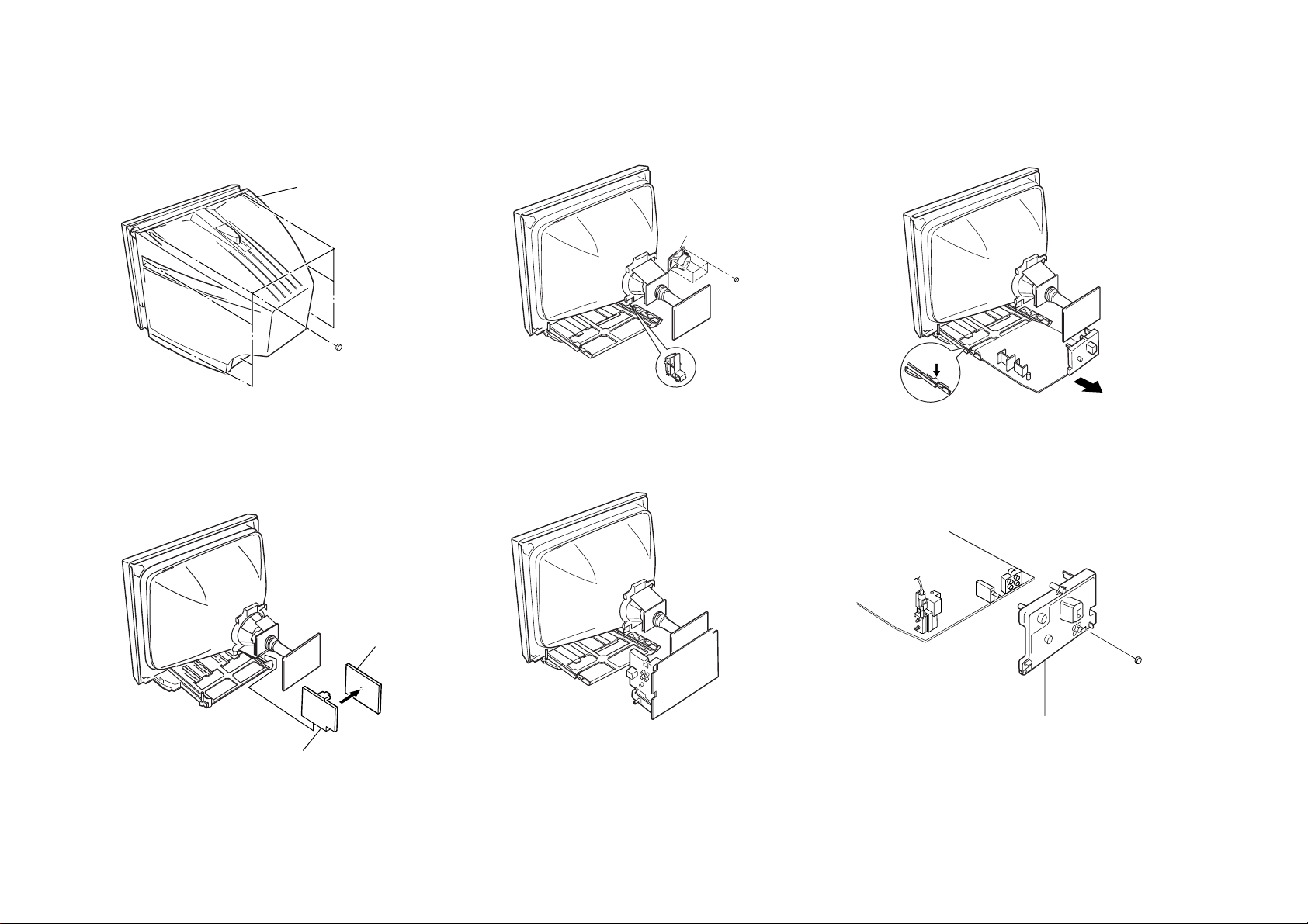
1 Eight screws
(+BVTP 4 × 16)
1 Rear Cover
1 Four screws
washer head
(BVTP 3 × 12)
CRT SUPPORT BLOCK
Speaker
Push claw
F Board
Bracket F1 PC Board
1 One screw
(+BVTP 4 × 16)
2 Terminal Bracket
2-1. REAR COVER REMOVAL
– 10 –
2-4. F BOARD REMOVAL
SECTION 2
DISASSEMBLY
2-2. SPEAKER REMOVAL
2-5. SERVICE POSITION
RM-915
2-3. CHASSIS ASSY REMOVAL
2-6. TERMINAL BRACKET REMOVAL
Caution:
Do not take out CRT support block while TV set in
standing position.
Note:
Undress necessary wires that creates tension while
placing the chassis into Service Position.
2-7. REPLACEMENT OF PARTS
One screw
(+BVTP 3 × 12)
1 Push to direction of arrow
and remove
7
5
8
Demagnetic coil
1 Four screws
(washer head)
(BVTP 3 × 12)
4 Two screws
(Tapping 5+
Crown Washer)
2 Speaker
(5 × 9cm)
0Tension
Beznet
hook
spring
Chassis assy
Deflection
yoke
C board
Coating earth assy
!¢ Picture tube
!£ Cushion
3
Two screws
(Tapping 5 +
Crown Washer)
6
Holder DGC
Cushion DGC
Cushion DGC
!™
!∞
!¡
A Board
Slim Beznet
CRT Support Block
9
Anode
cap
For replacements of light guide,unscrew them, exchange with
new parts and fix them with screws respectively.
2-7-1. Replacement of Light Guide
2-7-2. Replacement of Power Button
– 11 –
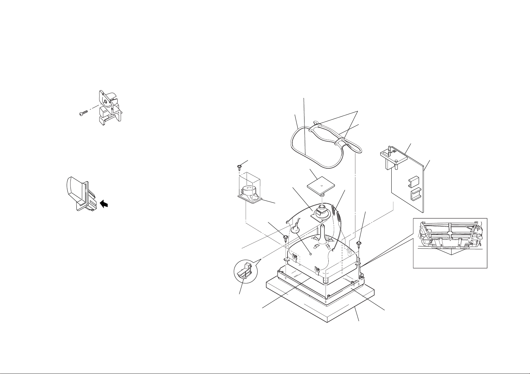
2-8. PICTURE TUBE REMOVAL
Note:
• Please make sure the TV set is not in standing position before removing necessary
CRT support located on bottom right and left.
KV-PG14N70
RM-915
KV-PG14N70
a
a
b
b
Anode button
c
• REMOVAL OF ANODE-CAP
NOTE : After removing the anode, short circuit the anode of the picture tube and
the anode cap to the metal chassis, CRT shield or carbon paint on the
CRT.
• REMOVING PROCEDURES
1 Turn up one side of the rubber cap in the direction indicated by the arrow a.
– 12 –
2 Using a thumb pull up the rubber cap firmly in the direction indicated by the arrow b.
RM-915
3 When one side of the rubber cap is separated from the anode button, the anode-cap
can be removed by turning up the rubber cap and pulling it up in the direction of the
arrow c.
• HOW TO HANDLE AN ANODE-CAP
1 Do not damage the surface of anode-caps with sharp shaped objects.
2 Do not press the rubber too hard so as not to damage the inside of anode-cap.
A metal fitting called the shatter-hook terminal is built into the rubber.
3 Do not turn the foot of rubber over too hard.
The shatter-hook terminal will stick out or damage the rubber.
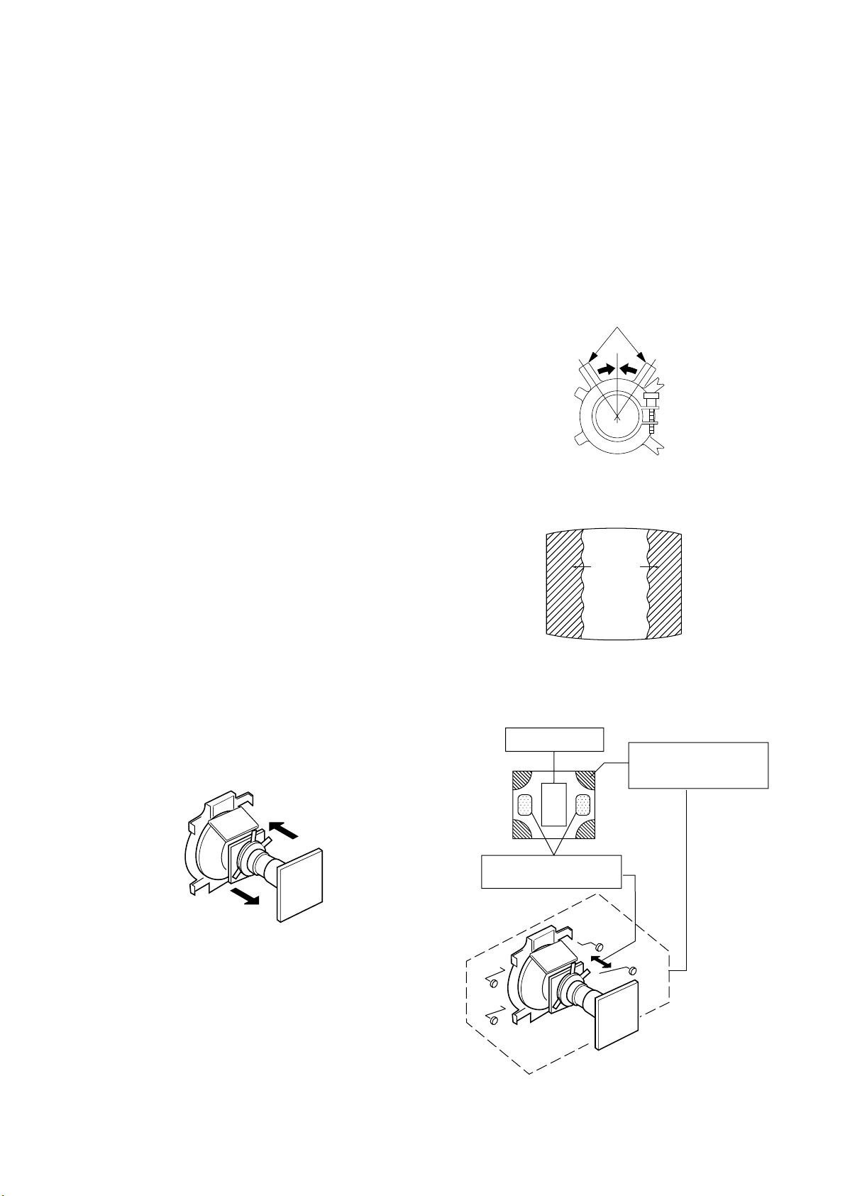
SECTION 3
SET-UP ADJUSTMENTS
KV-PG14N70
RM-915
The following adjustments should be made when a complete
realignment is required or a new picture tube is installed.
These adjustments should be performed with rated power
supply voltage unless otherwise noted.
Perform the adjustments in the following order :
1. Beam Landing
2. Convergence
3. Focus
4. White Balance
Controls and switches should be set as follows unless otherwise
noted:
PICTURE control ........................................................... normal
BRIGHTNESS control................................................... normal
................................................................................................................................................................................................................................
Preparation :
In order to reduce the influence of geomagnetism on the
Note : Test Equipment Required.
1. Pattern Generator
2. Degausser
3. Oscilloscope
Purity control
set's picture tube, face it east or west.
Switch on the set's power and degauss with the degausser.
3-1. BEAM LANDING
1. Input a white signal with the pattern generator.
Contrast
Brightness
2. Set the pattern generator raster signal to a green raster.
3. Move the deflection yoke to the rear and adjust with the
purity control so that the green is at the center and the blue
and the red take up equally sized areas on each side.
(See Figures 3-1 through 3-4.)
4. Move the deflection yoke forward and adjust so that the
entire screen is green. (See Figure 3-1.)
5. Switch the raster signal to blue, then to red and verify the
condition.
6. When the position of the deflection yoke has been decided,
fasten the deflection yoke with the screws and DY spacers.
7. If the beam does not land correctly in all the corners, use a
magnet to adjust it.
(See Figure 3-4.)
}
normal
Red
Purity control
corrects this area.
b
a
Fig. 3-2
Blue
Green
Fig. 3-3
Disk magnets or rotatable
disk magnets correct these
areas (a-d).
Fig. 3-1
– 13 –
c
Deflection yoke positioning
corrects these areas.
a
d
d
b
Fig. 3-4
c
 Loading...