

Page 1
SERVICE MANUAL
MODEL COMMANDER DEST. CHASSIS NO. MODEL COMMANDER DEST. CHASSIS NO.
BG-1L
CHASSIS
KV-EF29N6A
KV-EF29N6B
KV-EF29N9P
RM-882 AN SCC-N80A-A
RM-882 BRZ SCC-N79A-A
RM-882 MX SCC-N78A-A
MICROFILM
∗ Please file according to model size. ...
29
TRINITRON
®
COLOR TV
Page 2

KV-EF29N6A/EF29N6B/EF29N9P
RM-882
Specifications
Power requirements
Power consumption (W)
Color system
Stereo system
On-screen language
Channel coverage
˘(Antenna)
Audio output (speaker)
Number of terminal
VIDEO
AUDIO
S1 VIDEO
COMPONENT VIDEO
2 (Headphones)
Picture tube
Tube size (cm)
Screen size (cm)
Dimensions (w/h/d, mm)
Mass (kg)
Design and specifications are subject to change without notice.
KV-EF29N6B KV-EF29N6A, KV-EF29N9P Note
110-240 V AC, 50/60 Hz
183
NTSC, PAL M NTSC, PAL N
MTS
English/Spanish
VHF : 2-13/UHF : 14-69/CATV : 1-125
75-ohm external terminal
15W + 15W
Input: 4 Output: 1 phono jacks; 1 Vp-p, 75 ohms
Input: 4 Output: 1 phono jacks; 500 mVrms
Input: 2 Y: 1 Vp-p, 75 ohms,
Input: 1 phono jacks
Output: 1 Minijack
29 in.
72
68
716 × 572 × 525
54
unbalanced, sync negative
C: 0.286 Vp-p, 75 ohms
Y: 1.0 Vp-p, 75 ohms,
sync negative
C
B
: 0.7 Vp-p, 75 ohms
C
R
: 0.7 Vp-p, 75 ohms
Audio: 500 mVrms
Measured
diagonally
Measured
diagonally
CAUTION
SHORT CIRCUIT THE ANODE OF HTE PICTURE TUBE
AND THE ANODE CAP TO THE METAL CHASSIS, CRT
SHIELD, OR CARBON PAINTED ON THE CRT, AFTER
REMOVING THE ANODE.
SAFETY-RELATED COMPONENT WARNING!!
COMPONENTS IDENTIFIED BY SHADING AND MARK
¡ ON THE SCHEMATIC DIAGRAMS, EXPLODED
VIEWS AND IN THE PARTS LIST ARE CRITICAL TO
SAFE OPERATION. REPLACE THESE COMPONENTS
WITH SONY PARTS WHOSE PART NUMBERS APPEAR AS SHOWN IN THIS MANUAL OR IN SUPPLEMENTS PUBLISHED BY SONY.
– 2 –
Page 3

TABLE OF CONTENTS
Section Title PageSection Title Page
KV-EF29N6A/EF29N6B/EF29N9P
RM-882
1. GENERAL ................................................................. 4
2. DISASSEMBLY
2-1. Rear Cover Removal ......................................... 20
2-2. Speaker Box Assy Removal .............................. 20
2-3. Chassis Assy Removal ...................................... 20
2-4. Service Position ................................................. 20
2-5. Terminal Bracket, Printed Wiring Board Holder,
DH Bracket Removal ........................................ 21
2-6. Picture Tube Removal ........................................ 22
2-7. Wiring Harness Layout ...................................... 23
3. SET-UP ADJUSTMENTS................................... 24
3-1. Beam Landing ................................................... 24
3-2. Convergence ...................................................... 25
3-3. Focus Adjustment .............................................. 28
3-4. G2 (Screen) and White Balance Adjustments ... 29
4. SELF DIAGNOSIS FUNCTION ..................... 30
5. CIRCUIT ADJUSTMENTS ................................ 31
5-1. Adjustments with Commander ......................... 31
5-2. Adjustment Method ........................................... 32
5-3. Picture Quality Adjustments ............................. 37
5-4. Display Position Adjustments ........................... 37
5-5. A Board Adjustment After IC003
(MEMORY) Replacement ................................ 38
6. DIAGRAMS
6-1. Block Diagrams .................................................. 39
6-2. Circuit Boards Location ..................................... 52
6-3. Schematic Diagrams and Printed Wiring
Boards ................................................................. 53
(1) Schematic Diagram of A Board ........................ 57
(2) Schematic Diagrams of H7, J, P3 and
P4 Boards ........................................................... 62
(3) Schematic Diagrams of B3, C1 and
VM Boards ........................................................ 73
(4) Schematic Diagrams of D, D2 and
DH Boards ......................................................... 78
(5) Schematic Diagrams of A4, A5 and
S1 Boards ........................................................... 86
6-4. Semiconductors ................................................. 91
7. EXPLODED VIEWS
7-1. Speaker Box ...................................................... 93
7-2. Chassis ............................................................... 94
7-3. Picture Tube ...................................................... 95
8. ELECTRICAL PARTS LIST ............................ 97
– 3 –
Page 4

The operating instructions mentioned here are partial abstracts
4
Using Your New TV
VIDEO
VIDEO IN
VIDEO OUT
AUDIO
VIDEO IN MON/TV
OUT
VIDEO
L
(
MONO
)
AUDIO
R
S1 VIDEO
Getting Started
Step 1
Connect the antenna
If you wish to connect a VCR, see the “Connecting a VCR” diagram below.
Connecting a VCR
Using Your New TV
To video and
audio outputs
VCR
VIDEO (yellow)
AUDIO-L (MONO)(white)
AUDIO-R (red)
To S video
output
Antenna cable
(not supplied)
To VIDEO IN 1,
2, or 3
Audio/Video cable
(not supplied)
S video cable
(not supplied)
: Signal flow
To S1 VIDEO
To antenna
output
To ˘
(antenna)
or
: Signal flow
Antenna
cable
(supplied)
Antenna cable
(not supplied)
Antenna
connector
(not supplied)
Antenna cable
(supplied)
5
Using Your New TV
Using Your New TV
Notes
• If you connect a monaural VCR, connect the yellow plug to VIDEO (the
yellow jack) and the black plug to AUDIO-L (MONO) (the white jack).
• If you connect a VCR to the ˘ (antenna) terminal, preset the signal
output from the VCR to the program position 0 on the TV.
• Do not simultaneously connect video equipment to the VIDEO 3 INPUT
jacks at the front and the VIDEO IN 3 jacks at the rear of your TV.
• If both S1 VIDEO and VIDEO of VIDEO IN 1 are input simultaneously, the
S1 VIDEO is automatically selected. To view the video input to VIDEO IN
1, disconnect the S video cable.
• When no signal is input to the connected VCR (or video equipment), the
screen becomes blue.
Step 2
Insert the batteries
into the remote
Note
• Do not use old batteries nor use different types of batteries together.
Step 3
Preset the channels
Notes
• When you use the TV for the first time, preset the channels by
pressing AUTO PROGR button inside the front cover.
• If you use a cable TV system, select “CABLE : ON” of the
PRESET menu before presetting the channels. (See “Changing
other PRESET menu options” on page 30.)
Now You Are Ready. . .
The channels are now automatically preset in your TV. T o preset the channels
manually, see “Adding or erasing channels” on page 28.
1
2
AUTO
PROGR
1
MAIN POWER
ONE-PUSH AUTOMATIC PROGRAMING
MAIN POWER
VIDEO 3 INPUT
(
MONO
)
AUDIO
VIDEO
S1 VIDEO
AUTO PROGRAM
1
from the Operating Instruction Manual. The page numbers of
the Operating Instruction Manual remain as in the manual.
– 4 –
SECTION 1
GENERAL
Page 5
6
Using Your New TV
VIDEO 3 INPUT
(
MONO
)
AUDIO
VIDEO
S1 VIDEO
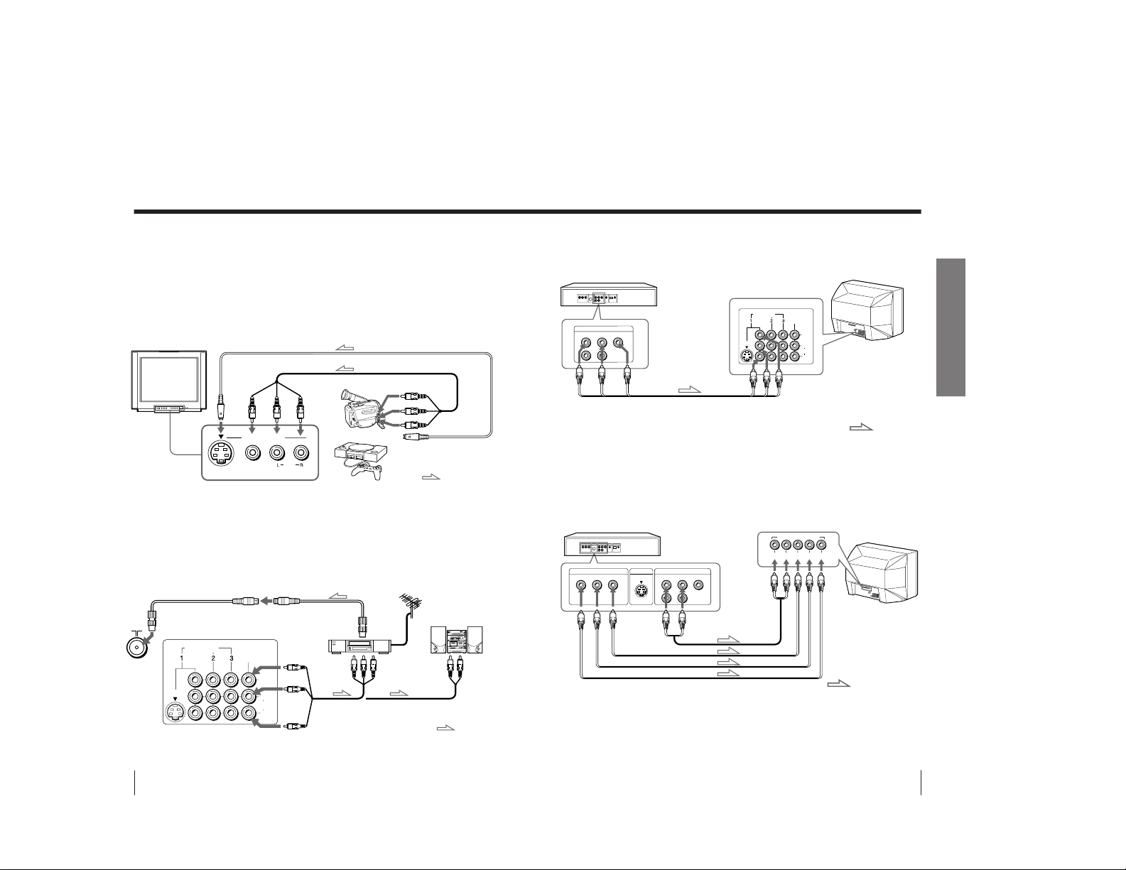
Connecting optional components
You can connect optional audio/video components, such as a VCR, multi disc player,
camcorder, video game or stereo system. If you connect a cable box, contact your
CATV provider.
Connecting a camcorder/video game equipment
using the VIDEO 3 INPUT jacks
Notes
• You can also connect video equipment to the VIDEO IN 3 jacks at the rear
of your TV.
• Do not simultaneously connect video equipment to the VIDEO 3 INPUT
jacks at the front and the VIDEO IN 3 jacks at the rear of your TV;
otherwise, the picture will not be displayed properly on the screen.
Connecting audio/video equipment using the
MON/TV OUT jacks
Note
• When connecting a monaural VCR, connect the yellow plug to VIDEO (the yellow
jack) and the black plug to AUDIO -L (MONO) (the white jack).
To S video output
Front of TV
Camcorder
Video game
equipment
To video and
audio outputs
VIDEO (yellow)
AUDIO-L
(MONO) (white)
AUDIO-R (red)
Rear of TV
To
antenna
output
To video and
audio inputs
or
Audio system
To
audio
inputs
VCR
:Signal flow
:Signal flow
To
S1 VIDEO
To VIDEO 3
INPUT
To MON/TV
(monitor/
TV) OUT
or
Audio/Video cable (not supplied)
S video cable (not supplied)
Antenna cable (not supplied)
Audio/Video cable
(not supplied)
Antenna cable (supplied)
VIDEO IN MON/TV
OUT
VIDEO
L
(
MONO
)
AUDIO
R
S1 VIDEO
7
Using Your New TV
Using Your New TV
Connecting a DVD player
Using the AUDIO/VIDEO connectors, connect VIDEO IN 1 on your TV to LINE OUT
on your DVD player.
Connecting a DVD player with component video output
connectors
1 Using audio connectors, connect L and R of COMPONENT VIDEO (DVD) IN on
your TV to the AUDIO L and R output connectors on your DVD player.
2 Using three yellow video cables, connect Y, C
B
, and CR of COMPONENT VIDEO
(DVD) IN on your TV to Y, C
B
, and CR output on your DVD player.
Notes
• Some DVD player terminals may be labeled Y, B-Y, and R-Y. If so, connect
Y (green) to Y, C
B
(blue) to B-Y, and C
R
(red) to R-Y.
• Since the high quality pictures on a DVD disc contain a lot of information,
picture noise may appear. In this case, adjust the sharpness (“SHARP”) in
the VIDEO ADJUST menu. (see page 22.)
• Connect your DVD player directly to your TV. Connecting the DVD
player through other video equipment will cause unwanted picture noise.
DVD player
Audio/Video cable
(not supplied)
DVD player
To
L (white)
R (red)
Audio cable
(not supplied)
To component
video output
Video cable (not supplied)
VIDEO (yellow)
AUDIO-L (MONO) (white)
AUDIO-R (red)
To VIDEO IN 1,
2, or 3
: Signal flow
To audio
output
:Signal flow
To COMPONENT
VIDEO (DVD) IN
VIDEO IN MON/TV
OUT
VIDEO
L
(
MONO
)
AUDIO
R
S1 VIDEO
VIDEO
R-AUDIO-L
LINE OUT
VIDEO
R-AUDIO-L
LINE OUT
Y
COMPONENT VIDEO OUT
S VIDEO OUT
CBCR
YCB CRLR
COMPONENT VIDEO(DVD) IN
– 5 –
Page 6

8
Using Your New TV
Securing the TV
To prevent the TV from falling, secure the TV using one of the following methods:
A
With the supplied screws, attach the band to the TV stand and to the rear of
the TV using the provided hole.
B
Put the cord or chain through the clamps to secure the TV against a wall or
pillar.
Note
• Use only the supplied screws. Use of other screws may damage the TV.
20
mm
AB
3.8mm
9
Using Your New TV
Using Your New TV
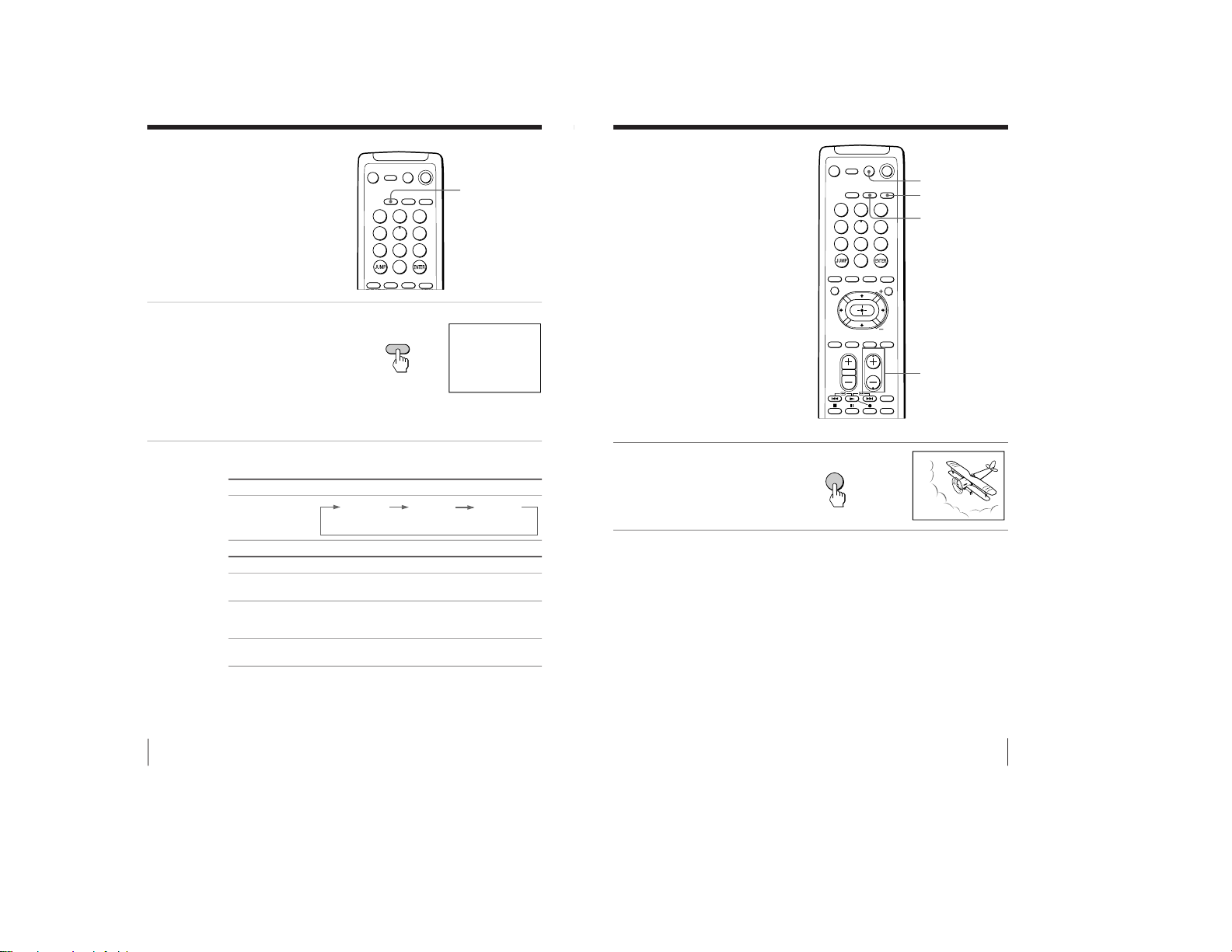
Watching the TV
This section explains functions used
while watching TV. Most operations can
be done using the remote.
1
Press MAIN POWER to
turn on the TV.
When the TV is in the standby
mode (the STANDBY/
STEREO/WAKE UP indicator
on the TV is lit), press POWER
on the remote or POWER u
on the TV.
The CHANNEL (CH) +/–,
VOLUME . +/–, TV/VIDEO
…, and POWER u indicators
on the TV light up.
2
Press CH +/– or number
buttons to select the TV
program.
For double digit numbers,
press the numbers, then
ENTER (e.g., for 25, press 2
and 5, then ENTER).
MUTING
DISPLAY
POWER
VIDEO
TV
Number buttons
JUMP
VOL +/–
MAIN POWER
CH +/–
continued
WAKE UP
SLEEP
ENTER
CH
1
2
3
4
5
6
7
8
0
9
MAIN POWER
1
2
3
4
5
6
7
8
0
9
MUTING DISPLAY GAME
POWER
MTS VIDEO TV
TV/VIDEO FREEZE
SWAP PIP
DVD MENU
MENU
PIP CH
DYNAMIC
P.BASSO
WAKE UP SLEEP VIRTUAL
DOLBY
VOL CH
POWER
VIDEO
TITLE
– 6 –
Page 7

10
Using Your New TV
To
Turn off temporarily
Turn off completely
Adjust the volume
Mute the sound
Watch the video input
Jump back to the previous channel
Display the on-screen information*
Change the on-screen language
Do this
Press POWER.
The STANDBY/STEREO/WAKE UP indicator on the
TV lights up.
Press MAIN POWER on the TV.
Press VOL +/– (or VOLUME . +/– on the TV).
Press MUTING.
Press VIDEO (or TV/VIDEO … on the TV) to select
“VIDEO 1”, “VIDEO 2”, “VIDEO 3” or “DVD”.
To go back to the TV program, press TV (or TV/VIDEO
… on the TV).
Press JUMP.
Press DISPLAY.
See page 21.
* The picture, sound, and either the program position or video mode are
displayed. The on-screen display for the picture and sound information
disappears after about 3 seconds.
Notes
• When you turn on the TV, you may hear a “boon” sound that is caused by
the demagnetization of the TV. This does not indicate a malfunction.
• When you turn the TV on soon after having turned it off, the picture may
be distorted. This is caused by the demagnetization of the TV and does
not indicate a malfunction.
Additional tasks
Watching the TV (continued)
11
Using Your New TV
Using Your New TV
To set the Wake Up timer
1 Press WAKE UP until the desired period of time appears.
Every time you press this button, the period of time changes as
follows:
2 Select the TV program or video mode you want to display when
you wake up.
3 Press POWER on the remote or set the Sleep timer if you want the
TV to turn off automatically.
To cancel the Wake Up timer, press WAKE UP until “WAKE UP
TIMER: OFF” appears or turn off the TV by pressing MAIN
POWER on the TV.
Notes
• The Wake Up timer starts immediately after the on-screen display
disappears.
• If no buttons or controls are pressed for more than two hours after the TV
is turned on using the Wake Up timer, the TV automatically goes into the
standby mode. To continue watching the TV, press any button or control
on the TV or the remote.
To set the Sleep timer
Press SLEEP until the desired period of time appears.
Every time you press this button, the period of time changes as
follows:
To cancel the Sleep timer, press SLEEP until “SLEEP TIMER: OFF”
appears or turn the TV off.
SLEEP TIMER:30M
SLEEP TIMER:60M
SLEEP TIMER:OFF
SLEEP TIMER:90M
After 30 minutes
No Sleep Timer
After 60 minutes
After 90 minutes
WAKE UP TIMER:10M
WAKE UP TIMER:OFF
WAKE UP TIMER:12H00M
After 10 minutes
No Wake Up Timer After 12 hours
– 7 –
Page 8

12
Advanced Operations
Listening with
dynamic sound
—DYNAMIC POWER BASSO
The DYNAMIC POWER BASSO sound
mode enables you to enjoy high quality
audio with the best combination of all
types of sound. It reproduces dynamic
and clear sounds and emphasizes low
and high audio effects as well.
Press DYNAMIC P. BASSO.
The sound mode of the TV
program or the video input
changes to the DYNAMIC
POWER BASSO sound.
To go back to the normal sound mode
Press DYNAMIC P. BASSO again.
Tip
• Select any of the sound modes (“HYPER SURROUND” or “A/V
CONTROL”–“DYNAMIC/STANDARD/SOFT/PERSONAL”) to cancel
the DYNAMIC POWER BASSO sound.
Advanced Operations
DYNAMIC
P. BASSO
b
POWER BASSO
:
ON
7
8
0
9
TV/VIDEO FREEZE
SWAP PIP
DVD MENU
MENU
PIP CH
DYNAMIC
P.BASSO
WAKE UP SLEEP VIRTUAL
DOLBY
VOL CH
POWER
VIDEO
TITLE
13
Advanced Operations
Advanced Operations
Listening with
Virtual Dolby*
Surround sound
The Virtual Dolby Surround sound
mode enables you to enjoy Dolby
ProLogic Surround without surround
speakers.
Press DOLBY VIRTUAL.
The sound mode of the TV
program or the video input
changes to the Virtual
Dolby Surround sound.
To go back to the normal sound mode
Press DOLBY VIRTUAL again.
* Manufactured under license from Dolby Laboratories Licensing Corpora-
tion.
DOLBY, the double-D symbol a and “PRO LOGIC” are trademarks of
Dolby Laboratories Licensing Corporation.
The Virtual Dolby Surround of this model consists of Dolby Pro
Logic and TruSurround.
“
TM
is a trademark of SRS Labs, Inc. SRS and the SRS
symbol are registered trademarks of SRS Labs, Inc. in the United
States and selected foreign countries. SRS and TruSurround are
incorporated under license from SRS Labs, Inc.”
DOLBY
VIRTUAL
b
DOLBY VIRTUAL : ON
0
TV/VIDEO FREEZE
SWAP PIP
DVD MENU
MENU
PIP CH
DYNAMIC
P.BASSO
WAKE UP SLEEP VIRTUAL
DOLBY
VOL CH
POWER
VIDEO
TITLE
– 8 –
Page 9

14
Advanced Operations
Watching two
programs at the
same time
—PIP
With the Picture-in-Picture (PIP) feature,
you can display a sub screen within the
main picture of different TV programs
or video inputs.
Displaying the PIP screen
Press PIP.
To select a TV program in the PIP screen
Press V or v, and press
.
To select a video input in the PIP screen
Press TV/VIDEO (or TV/VIDEO … on the TV).
To go back to the normal screen
Press PIP.
Tips
• You can also display the PIP screen using the menu (see “Adjusting the
PIP setting” on page 24).
• You can change the position of the PIP screen (see “Adjusting the PIP
setting” on page 24).
• You can also select a TV program in the PIP screen using the menu (see
“Adjusting the PIP setting” on page 24).
TV/VIDEO, FREEZE,
SWAP, PIP
b
V/v/
PIP
1
2
3
4
5
6
7
8
0
9
MUTING DISPLAY GAME
POWER
MTS VIDEO TV
TV/VIDEO FREEZE
SWAP PIP
DVD MENU
MENU
PIP CH
DYNAMIC
P.BASSO
WAKE UP SLEEP VIRTUAL
DOLBY
15
Advanced Operations
Additional PIP tasks
To
swap pictures between the main
and PIP screens
freeze the PIP screen
Notes
• When you display a video input on the PIP screen at a faster/slower
speed, the picture may be disrupted depending on the VCR type.
• If you display different color systems on the main screen and the PIP
screen, the size of the PIP screen may be different and the PIP picture may
be disrupted. This does not indicate a malfunction of the TV.
Press
SWAP
FREEZE
To unfreeze the screen, press the button again.
– 9 –
Page 10
16
Advanced Operations
Selecting a stereo
or bilingual
program
You can enjoy stereo sound or bilingual
programs of MTS stereo system.
Press MTS repeatedly until
you receive the sound you
want.
The on-screen display
changes to show the
selected sound. When the
unit receives a stereo
program, the STANDBY/
STEREO/WAKE UP
indicator lights up.
When receiving an MTS program
Tip
You can also select a type of MTS stereo system using the menu (see
“Changing other PRESET menu options” on page 30).
MTS
Broadcasting On-screen display (Selected sound)
MTS stereo
STEREO
b
STEREO
MONO
SAP
Choose To
STEREO listen to stereo sound while a stereo broadcast is
received
SAP listen to bilingual programs
The sound of non-SAP programs will be muted when
SAP is selected.
MONO select mono reception (Use to reduce noise during
stereo broadcast)
MTS
1
2
3
4
5
6
7
8
0
9
MUTING DISPLAY
GAME
POWER
MTS VIDEO TV
TV/VIDEO
FREEZE
SWAP PIP
17
Advanced Operations
Viewing a video
game screen
—GAME MODE
The GAME MODE feature optimizes the
video game screen by giving a soft
picture and dynamic sound effects.
Press GAME.
The picture and sound
change to the mode that is
suitable for video games.
To go back to the normal picture and sound modes
Press TV, VIDEO, or CH +/–.
Tips
• You can also view the video game screen using the menu (see “Adjusting
the FEATURES setting” on page 26).
• You can turn on the TV automatically and enter the GAME mode just by
pressing the GAME button when the TV is in the standby mode.
Note
• To display a video game screen, connect the video game equipment to the
VIDEO 3 INPUT jacks at the front or VIDEO IN 3 jacks at the rear of the
TV.
GAME
b
GAME
GAME
TV
VIDEO
CH +/–
1
2
3
4
5
6
7
8
0
9
MUTING DISPLAY GAME
POWER
MTS VIDEO TV
TV/VIDEO FREEZE
SWAP PIP
DVD MENU
MENU
PIP CH
DYNAMIC
P.BASSO
WAKE UP SLEEP VIRTUAL
DOLBY
VOL CH
POWER
VIDEO
TITLE
– 10 –
Page 11

18
Advanced Operations
Operating
optional
components
You can use the supplied remote to
operate Sony video equipment such as
Beta, 8mm, VHS, MDP, CD or DVD.
Setting the remote to the connected equipment
While holding down
VIDEO POWER, press the
following number
combinations to enter the
equipment’s code number
(see the chart below).
Sony video equipment’s code numbers
Notes
• If your video equipment is furnished with a COMMAND MODE selector,
set this selector to the same position as the setting code.
• If the equipment does not have a certain function, the corresponding
button on the remote will not operate.
• When you remove the batteries, the code number may revert to the factory
setting.
Number buttons
DVD MENU
Video equipment
operation buttons
V/b/v/B/
b
To control
DVD
VTR1 (Beta)
VTR2 (8mm)
VTR3 (VHS)
MDP
CD
MD
For example, to operate a
Sony 8 mm VCR:
Hold down VIDEO POWER and press
00
01
02
03
04
06
07
VIDEO POWER
0
2
+
POWER
VIDEO
1
2
3
4
5
6
7
8
0
9
TV/VIDEO FREEZE SWAP PIP
DVD MENU
MENU
PIP CH
DYNAMIC
P.BASSO
WAKE UP SLEEP VIRTUAL
DOLBY
VOL CH
POWER
VIDEO
TITLE
19
Advanced Operations
Operating a VCR using the remote
Operating a DVD player using the remote
Operating an MDP using the remote
To
turn on/off
record
play
stop
fast forward
rewind the tape
pause
search the picture forward or
backward
Press
VIDEO POWER
r while pressing (
(
p
)
0
P
Press again to resume normal playback.
) or 0 during playback.
Release to resume normal playback.
To
turn on/off
play
stop
pause
step through different tracks of
an audio disc
display the Title menu
display the menu
select the menu item
Press
VIDEO POWER
(
p
P
Press again to resume normal playback.
+ to step forward or = to step
backward
TITLE
DVD MENU
V/b/v/B while holding down
r
To
turn on/off
play
stop
pause
search the picture forward or
backward
Press
VIDEO POWER
(
p
P
Press again to resume normal playback.
) or 0 during playback.
Release to resume normal playback
– 11 –
Page 12

20
Adjusting Your Setup (MENU)
Adjusting Your Setup (MENU)
Introducing the
menu system
The MENU button lets you open a menu and change the settings of your TV. Here’s
an overview of the menu system.
A/V CONTROL PIP FEATURES PRESET
How to use the menu
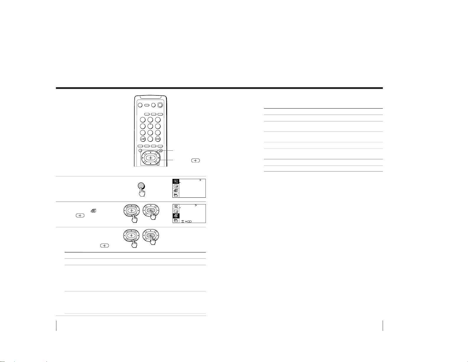
1 After pressing MENU, press
V/b/v/B to move the cursor (”)
in four directions to select an item.
2 Press
to
confirm the selection.
To
go back to the previous menu
cancel the menu
change the menu language
Do this
Press V or v to move the cursor (
”
) to the first line (N) of
each menu, then press
.*
Press MENU.
See next page.
* Except for “AUTO PROGRAM”
Notes (except for AUTO PROGRAM)
• When you select a menu, the color of the menu and the menu symbol
change and the cursor (
”
) appears beside the first item of the menu.
• When an item on the menu is selected after pressing
, the color of
the item changes.
• If more than 60 seconds elapse between entries, the menu screen
disappears.
• Some menu displays contain the symbol
at the bottom of the
screen to indicate how to use the menu.
A / V CONTROL
DYNAMIC
SOFT
STA NDARD
PERSONAL
V I DEO ADJUST
AUDIO ADJ UST
T I LT CORRECT : 0
PRESET
MTS:STEREO
SYSTEM:AUTO
CABLE : OF F
ENGL I SH
AUTO P ROGRAM
MANUAL PROGRAM
LANGUAGE/IDIOMA
:
GAME MODE
HYPER SURR
OUND :
OF F
MONITOR
AV OUT :
FE ATURES
P I CTURE
40
100
0
80
V I DEO ADJUST
COLOR
BR I GHT
HUE
SHARP
VM: HIGH
45
0
BASS
80
00
80
TREBLE
BALANCE
AUDIO ADJ UST
PIP
PIP: OFF
POS I T I ON:
7
8
0
9
TV/VIDEO FREEZE
SWAP PIP
DVD MENU
MENU
PIP CH
DYNAMIC
P.BASSO
WAKE UP SLEEP VIRTUAL
DOLBY
VOL CH
1
AUTO PROGRAM
ERASE
ATTENUATOR : OFF
CHANNEL: 1 10
ADD
MANUAL PROGRAM
21
Adjusting Your Setup (MENU)
Changing the
menu language
You can change the menu language as
well as the on-screen language.
1
Press MENU.
2
Press V or v to move the
cursor (”) to the PRESET
menu (
), then press
.
3
Make sure the cursor (”)
appears beside
LANGUAGE/IDIOMA, then
press
.
4
Press V/b/v/B to select
ESPAÑOL, then press
.
The menu language
changes to Spanish.
To go back to the normal screen
Press MENU.
MENU
V/b/v/B/
MENU
b
b
b
b
Adjusting Your Setup (MENU)
A / V CONTROL
DYNAMIC
SOFT
STA NDARD
PERSONAL
V I DEO ADJUST
AUDIO ADJ UST
T I LT CORRECT : 0
PRESET
MTS:STEREO
SYSTEM:AUTO
CABLE : OF F
ENGL I SH
AUTO P ROGRAM
MANUAL PROGRAM
LANGUAGE/IDIOMA
:
PRESET
MTS:STEREO
SYSTEM:AUTO
CABLE : OF F
ENGL I SH
AUTO P ROGRAM
MANUAL PROGRAM
LANGUAGE/IDIOMA
:
1
2
3
4
5
6
7
8
0
9
MUTING DISPLAY
GAME
POWER
MTS VIDEO TV
TV/VIDEO FREEZE SWAP PIP
DVD MENU
MENU
PIP CH
PREAJUSTE
MTS:ESTEREO
SISTEMA:AUTO
CABLE : APAGADO
ESPANOL
AUTO P ROGRAMA
PROGRAMA MANUA L
IDIOMA/LANGUAGE:
˜
– 12 –
Page 13
22
Adjusting Your Setup (MENU)
MENU
b
b
Select
DYNAMIC
STANDARD
SOFT
PERSONAL
VIDEO ADJUST*
AUDIO ADJUST*
TILT CORRECT
A / V CONTROL
DYNAMIC
SOFT
STA NDARD
PERSONAL
V I DEO ADJUST
AUDIO ADJ UST
T I LT CORRECT : 0
A / V CONTROL
DYNAMIC
SOFT
STA NDARD
PERSONAL
V I DEO ADJUST
AUDIO ADJ UST
T I LT CORRECT : 0
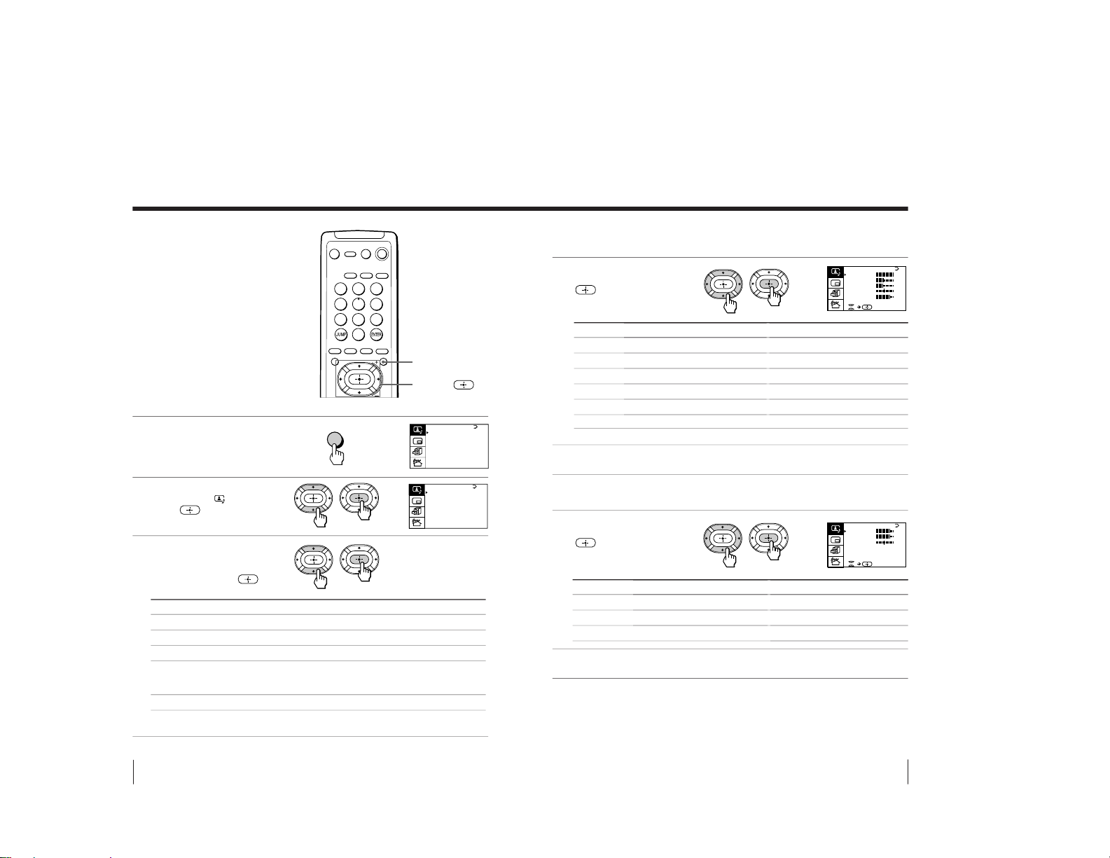
Adjusting the A/V
CONTROL setting
The A/V CONTROL menu allows you
to adjust the picture and sound settings.
1
Press MENU.
2
Press V or v to move the
cursor (”) to (
), then
press
.
3
Press V or v to move the
cursor (”) to the desired
option (see the table
below), then press
.
* When you select “VIDEO ADJUST” or “AUDIO ADJUST”, options for
your selection are displayed (see below).
To
receive high contrast pictures with powerful sound.
receive normal contrast pictures with medium listening sound.
receive mild pictures with soft sound.
receive the last picture/sound settings that are adjusted using
“VIDEO ADJUST*” and “AUDIO ADJUST*”.
adjust the picture tilt when it is not aligned to the TV screen.
MENU
V/b/v/B/
1
2
3
4
5
6
7
8
0
9
MUTING DISPLAY
GAME
POWER
MTS VIDEO TV
TV/VIDEO FREEZE SWAP PIP
DVD MENU
MENU
PIP CH
23
Adjusting Your Setup (MENU)
Adjusting the VIDEO ADJUST settings
1
Press V/b/v/B to adjust the
selected item, then press
.
* You can adjust HUE for the NTSC color system only.
2
Repeat the above step to
adjust other items.
Adjusting the AUDIO ADJUST settings
1
Press V/b/v/B to adjust the
selected item, then press
.
2
Repeat the above step to
adjust other items.
To go back to the normal screen
Press MENU.
Tip
• For details on the menu system and how to use the menu, refer to the
“Introducing the menu system” section on page 20.
For
PICTURE
COLOR
BRIGHT
HUE*
SHARP
VM
Press V/b to
increase picture contrast
increase color intensity
brighten the picture
make picture tones greenish
sharpen the picture
increase emphasis on picture edges
Press v/B to
decrease picture contrast
decrease color intensity
darken the picture
make picture tones reddish
soften the picture
decrease emphasis on picture edges
For
BASS
TREBLE
BALANCE
Press v/B to
decrease the bass
decrease the treble
increase the left speaker’s volume
Press V/b to
increase the bass
increase the treble
increase the right speaker’s volume
b
b
P I CTURE
40
100
0
80
V I DEO ADJUST
COLOR
BR I GHT
HUE
SHARP
VM: HIGH
45
0
BASS
80
00
80
TREBLE
BALANCE
AUDIO ADJ UST
– 13 –
Page 14

24
Adjusting Your Setup (MENU)
Adjusting the PIP
setting
The PIP menu allows you to use the
Picture-in-Picture (PIP) feature.
1
Press MENU.
2
Press V or v to move the
cursor (”) to (
), then
press
.
MENU
V/b/v/B/
MENU
b
b
A / V CONTROL
DYNAMIC
SOFT
STA NDARD
PERSONAL
V I DEO ADJUST
AUDIO ADJ UST
T I LT CORRECT : 0
1
2
3
4
5
6
7
8
0
9
MUTING DISPLAY
GAME
POWER
MTS VIDEO TV
TV/VIDEO FREEZE SWAP PIP
DVD MENU
MENU
PIP CH
PIP
PIP: OFF
POS I T I ON:
25
Adjusting Your Setup (MENU)
3
Press V or v to move the
cursor (”) to the desired
option (see the table
below), then press
.
Tip
• For details on the menu system and how to use the menu, see the
“Introducing the menu system” section on page 20.
Select
PIP
POSITION
To
display a sub screen within the main picture.
Press V/b/v/B to select “ON”, then press
.
To cancel, press PIP or select “OFF”, then press
.
change the position of the PIP screen.
Press V/b/v/B to select the desired position, then press
.
To cancel, press MENU.
– 14 –
Page 15
26
Adjusting Your Setup (MENU)
Adjusting the
FEATURES setting
The FEATURES menu allows you to
optimize the screen for video games,
enjoy “surround” sound effects, and
select the output signal of the TV
broadcast or the connected equipment.
1
Press MENU.
2
Press V or v to move the
cursor (”) to (
), then
press
.
3
Press V or v to move the
cursor (”) to the desired
option (see the table
below), then press
.
MENU
b
b
Select
GAME MODE
HYPER SURROUND
AV OUT
(advanced rec-out)
MENU
V/b/v/B/
To
view a video game screen
enjoy “surround” sound effects of a concert hall or
movie theater.
Press V/b/v/B to select “DOLBY VIRTUAL”,
“MOVIE”, “MUSIC”, “NEWS<BBE
1)
>”,
“HALL<SRS
2)
>”, or “SPACE
3)”
(see below for details on
each item).
select the signal output through the MON/TV OUT
terminal.
Press V/b/v/B to select “TV” (to output the TV
broadcast signal) or “MONITOR” (to output the signal
of the equipment connected to the TV).
A / V CONTROL
DYNAMIC
SOFT
STA NDARD
PERSONAL
V I DEO ADJUST
AUDIO ADJ UST
T I LT CORRECT : 0
GAME MODE
HYPER SURROUND:
OF F
MONITOR
AV OUT :
FE ATURES
1
2
3
4
5
6
7
8
0
9
MUTING DISPLAY
GAME
POWER
MTS VIDEO TV
TV/VIDEO FREEZE SWAP PIP
DVD MENU
MENU
PIP CH
27
Adjusting Your Setup (MENU)
Description of adjustable HYPER SURROUND items
1)
The BBE is manufactured by Sony Corporation under license from BBE
Sound, Inc. It is covered by U.S. Patent No. 4,638,258 and No. 4,482,866.
The word “BBE” and the BBE symbol are the trademarks of BBE Sound,
Inc.
2)
The (r) SRS (SOUND RETRIEVAL SYSTEM) is manufactured by Sony
Corporation under license from SRS Labs, Inc. It is covered by U.S. Patent
No. 4,748,669. The word “SRS” and the SRS symbol (r) are registered
trademarks of SRS Labs, Inc.
3)
SPACE uses SRS MONO.
To go back to the normal screen
Press MENU.
Notes
• Do not change the channel and the input selection while recording with a
VCR through the MON/TV OUT jacks. If you change the channel and the
input selection, it also changes the channel and input selection that you
are recording.
• The signal of the PIP mode and the signal from the COMPONENT VIDEO
(DVD) IN connectors cannot be output even if “MONITOR” is selected.
Tip
• For details on the menu system and how to use the menu, see the
“Introducing the menu system” section on page 20.
To
listen to Dolby Surround encoded sound.
listen to sound that emphasizes the bass audio effect of
a movie theater.
listen to dynamic and clear sound that emphasizes the
low and high sound.
listen to sound that emphasizes voice.
listen to sound that spreads out over a large area,
giving the feeling of being at a concert hall.
listen to monaural sound with a stereo-like effect.
turn off the “surround” sound.
Select
DOLBY VIRTUAL
MOVIE
MUSIC
NEWS<BBE 1)>
HALL<SRS 2)>
SPACE
3)
OFF
– 15 –
Page 16

28
Adjusting Your Setup (MENU)
Adjusting the
PRESET setting
The PRESET menu allows you to adjust
the setup of your TV. For example, you
can receive a channel with a weak signal
that fails to be tuned in by automatic
presetting. In addition, the PRESET
menu offers other setup options, such as
changing the menu language.
Adding or erasing channels
1Press MENU.
2Press V or v to move the
cursor (”) to (
), then
press
.
3Press V or v to move the
cursor (”) to MANUAL
PROGRAM, then press
.
4
Press V or v to move the
cursor (”) to CHANNEL,
then press
.
5Press V/v until the
channel you want to add
or erase appears on the
menu, then press
.
MENU
b
b
MENU
V/b/v/B/
b
b
A / V CONTROL
DYNAMIC
SOFT
STA NDARD
PERSONAL
V I DEO ADJUST
AUDIO ADJ UST
T I LT CORRECT : 0
PRESET
MTS:STEREO
SYSTEM:AUTO
CABLE : OF F
ENGL I SH
AUTO P ROGRAM
MANUAL PROGRAM
LANGUAGE/IDIOMA
:
b
1
2
3
4
5
6
7
8
0
9
MUTING DISPLAY
GAME
POWER
MTS VIDEO TV
TV/VIDEO FREEZE SWAP PIP
DVD MENU
MENU
PIP CH
ERASE
ATTENUATOR : OFF
CHANNEL: 1 10
ADD
MANUAL PROGRAM
ERASE
ATTENUATOR : OFF
CHANNEL: 1 10
ADD
MANUAL PROGRAM
ERASE
ATTENUATOR : OFF
CHANNEL: 2 30
ADD
MANUAL PROGRAM
29
Adjusting Your Setup (MENU)
6
Press V or v to move the
cursor (”) to ADD or
ERASE, then press
.
If you want to add or
erase other channels,
repeat steps 3 to 5.
To go back to the normal screen
Press MENU.
Notes
• If the TV signal is too strong and the picture is distorted, select
“MANUAL PROGRAM” from the PRESET menu, then select
“ATTENUATOR: ON”.
• The ATTENUATOR setting is memorized for each channel.
• In weak broadcast signal areas, select “ATTENUATOR : OFF”.
continued
b
ERASE
ATTENUATOR : OFF
CHANNEL: 1 10
ADD
MANUAL PROGRAM
– 16 –
Page 17

30
Adjusting Your Setup (MENU)
Changing other PRESET menu options
1
Press MENU.
2
Press V or v to move the
cursor (”) to (
), then
press
.
3
Press V or v to move the
cursor (”) to the desired
option, then press
.
To go back to the normal screen
Press MENU.
Tip
• For details on the menu system and how to use the menu, refer to the
“Introducing the menu system” section on page 20.
Adjusting the PRESET setting (continued)
Select
LANGUAGE
AUTO PROGRAM
MANUAL PROGRAM
SYSTEM
CABLE
MTS
b
b
To
change the menu language (page 21)
preset channels automatically
preset channels manually. See “Adding or erasing
channels” on page 28.
select the color system.
Every time you press V/b/v/B, the menu item changes as
follows:
Normally, set this to “AUTO”.
select “ON” if you use a cable TV system.
select a type of MTS stereo system.
Press to select “STEREO”, “SAP”, or “MONO”.
For details, see “Selecting a stereo or bilingual program” on
page 16.
AUTO n PAL N n NTSC
n
(KV-EF29N6A/
N9P)
AUTO n PAL M n NTSC
n
(KV-EF29N6B)
A / V CONTROL
DYNAMIC
SOFT
STA NDARD
PERSONAL
V I DEO ADJUST
AUDIO ADJ UST
T I LT CORRECT : 0
PRESET
MTS:STEREO
SYSTEM:AUTO
CABLE : OF F
ENGL I SH
AUTO P ROGRAM
MANUAL PROGRAM
LANGUAGE/IDIOMA
:
31
Additional Information
Additional Information
Troubleshooting
If any problem persists, contact your nearest Sony dealer or authorized service center.
Dotted lines or stripes
Double images or “ghosts”
No picture
No sound
No color
Noisy soundSnowy picture
Good picture
No sound
Additional Information
continued
Symptom Check
• Check the antenna and antenna connection on the TV and
on the wall. (page 4)
• Display the PRESET menu and select “MANUAL
PROGRAM”. Then, select “ATTENUATOR : OFF”. (page
28)
• Display the A/V CONTROL menu and select
“STANDARD” or “SOFT.”
• Press MAIN POWER.
• Press MAIN POWER on the TV to turn off the TV for
about five seconds and then turn it on again.
• Check the power cord, antenna, and the VCR connections.
• Press VOL + or VOLUME .+ on the TV.
• Press MUTING.
• Press MTS.
• This may be caused by local interference (e.g. cars, neon
signs, hair dryers, etc.). Adjust the antenna direction for
minimum interference.
• This may be caused by reflections from nearby mountains
or buildings. A highly directional antenna may improve
the picture.
• Adjust the COLOR level in the VIDEO ADJUST menu of
the PERSONAL option. (page 23)
• Display the PRESET menu and check the color system
(SYSTEM) setting. (page 30)
• Display the A/V CONTROL menu and adjust “TILT
CORRECT.” (page 22)
Slant
– 17 –
Page 18

32
Additional Information
Symptom Check
• Even if the picture or the sound is normal, changes in
room temperature sometimes make the TV cabinet
expand or contract, making a noise. This does not indicate
a malfunction.
• The non-SAP programs will be muted when SAP is
selected. (page 16)
TV cabinet creaks.
Troubleshooting (continued)
No sound when SAP is
selected.
33
Additional Information
Identifying parts and controls
Refer to the pages indicated in parentheses ( ) for details.
Front panel
1 TV/VIDEO … button (10)
2 VOLUME Á +/– buttons (10)
3 CHANNEL (CH) +/– buttons (9)
4 POWER u button (9)
5 ENTER button (20)
6 MENU +/– buttons (20)
7 AUTO PROGR (program) button (5)
8 MAIN POWER button (9)
continued
ONE-PUSH AUTOMATIC PROGRAMMING
TV/VIDEO VOLUME
POWER
CH
MAIN POWER
CHANNEL
– 18 –
Page 19

34
Additional Information
Identifying parts and controls (continued)
1 MUTING button (10)
2 DISPLAY button (10)
3 GAME button (17)
4 POWER button (9)
5 VIDEO button (10)
6 TV button (10)
7 Number and ENTER buttons (9)
8 JUMP button (10)
9 MENU button (20)
0 V/b/v/B buttons (20)
Remote control
!¡ MTS button (16)
!™ PIP operation buttons (14 – 15)
TV/VIDEO
FREEZE
SWAP
PIP
V/v/
—for PIP CH
1
2
3
4
5
6
7
8
0
9
MUTING DISPLAY
GAME
POWER
MTS VIDEO TV
TV/VIDEO FREEZE SWAP PIP
DVD MENU
MENU
PIP CH
DYNAMIC
P.BASSO
WAKE UP SLEEP VIRTUAL
DOLBY
VOL CH
POWER
VIDEO
TITLE
1
2
3
4
5
6
7
8
0
9
MUTING DISPLAY
GAME
POWER
MTS VIDEO TV
TV/VIDEO FREEZE SWAP PIP
DVD MENU
MENU
PIP CH
DYNAMIC
P.BASSO
WAKE UP SLEEP VIRTUAL
DOLBY
VOL CH
POWER
VIDEO
TITLE
35
Additional Information
!£ DOLBY VIRTUAL button (13)
!¢ Timer setting buttons (11)
WAKE UP
SLEEP
!∞ DYNAMIC P(power). BASSO button
(12)
!§ VOL (volume) +/– buttons (10)
Button function
For general TV operations
For PIP operations
Names/symbols of buttons on the
remote are indicated in different
colors to represent the available
functions.
Label color
White
Yellow
!¶ DVD, VCR, MDP, CD, MD operation
buttons (19)
DVD MENU
+/# (fastforward/search
forward)
( (play)
=/3 (rewind/search
backward)
r (record)
p (stop)
P (pause)
VIDEO POWER
TITLE
1
2
3
4
5
6
7
8
0
9
MUTING DISPLAY GAME
POWER
MTS VIDEO TV
TV/VIDEO FREEZE
SWAP PIP
DVD MENU
MENU
PIP CH
DYNAMIC
P.BASSO
WAKE UP SLEEP VIRTUAL
DOLBY
VOL CH
POWER
VIDEO
TITLE
– 19 –
Page 20

KV-EF29N6A/EF29N6B/EF29N9P
RM-882
SECTION 2
DISASSEMBLY
2-1. REAR COVER REMOVAL
2 Rear cover
1 Six screws
(BVTP 4x16)
1 Five screws
(BVTP 4x16)
2-2. SPEAKER BOX ASS’Y REMOVAL
6 Speaker Box (L)
ass’y
5 Two tapping screws
(P 4x16)
4 Speaker Box (R)
3 Two tapping
screws (P 4x16)
ass’y
1 Two screws
(BVTP 4x16)
2 Speaker
stay
2-3. CHASSIS ASS’Y REMOVAL
1 Anode cap
(Refer to page 21)
A
2-4. SERVICE POSITION
2 Claw
2 Claw
3 Remove the chassis ass’y to
direction of the arrow A.
Chassis ass’y
– 20 –
Page 21

KV-EF29N6A/EF29N6B/EF29N9P
2-5. TERMINAL BRACKET, PRINTED WIRING BOARD HOLDER,
DH BRACKET REMOVAL
5 Printed wiring board holder
4 Claw
6 Screw
(BVTP 3x12)
7 DH bracket
1 Power cord
RM-882
2 Screw
(BVTP 3x12)
3 Terminal bracket
• REMOVAL OF ANODE-CAP
NOTE: Short circuit the anode of the picture tube and the anode cap to the metal chassis, CRT shield or carbon painted on the CRT, after
removing the anode.
• REMOVING PROCEDURES
c
b
a
Anode Button
1 Turn up one side of the rubber cap in
the direction indicated by the arrow a.
2 Using a thumb pull up the rubber cap
firmly in the direction indicated by the
arrow b.
• HOW TO HANDLE AN ANODE-CAP
1 Don’t hurt the surface of anode-caps with shartp shaped
material!
2 Don’t press the rubber hardly not to hurt inside of anode-caps!
A material fitting called as shatter-hook terminal is built in the
rubber.
3 Don’t turn the foot of rubber over hardly!
The shatter-hook terminal will stick out or hurt the rubber.
3 When one side of the rubber cap is
separated from the anode button, the
anode-cap can be removed by turning
up the rubber cap and pulling up it in the
direction of the arrow c.
– 21 –
Page 22

KV-EF29N6A/EF29N6B/EF29N9P
RM-882
2-6. PICTURE TUBE REMOVAL
!™ Demagnetic coil
0 Four claws
1 Two tapping screws
(P 4x16)
7 C1 board
8 Neck ass’y
!¡ Four DGC clip
6 Chassis ass’y
2 Speaker
box (L)
ass’y
5 Anode cap
9 Deflection
yoke
!£ Tension
spring
!¢ Two
screws
!¢ Two
screws
3 Two tapping
screws
(P 4x16)
(Refer to page 21)
4 Speaker
box (R)
ass’y
!∞ Picture tube
Cushion
– 22 –
Page 23

2-7. WIRING HARNESS LAYOUT
KV-EF29N6A/EF29N6B/EF29N9P
RM-882
Top switch Anode cap
NA rotation
coil
Speaker box (R)
ass’y
F
Connector
CN2601
A
CN2600
H
CN2605
CN0521
CN
1691
CN
DH
board
CN520
CN506
CN2601
1690
CN3804
C
CN
CN528
CN
526
CN909
907
CN106
CN701
CN904
CN
CN107
CN3305
CN108
CN120
H7 board
905
CN103
CN703
CN901
CN102
CN961
CN
704
C1 board
CN902
CN3304
CN117
VM board
E
CN3001
D
A board
B3 board
A5 board
B
Tension spring
Speaker box (L)
ass’y
G
Connector
D board
FBT
D2 board
CN2821
• DISASSEMBLED IN THE ORDER SHOWN BELOW
REAR COVER ..............................................1) Eleven screws
↓
SPEAKER BOX (L), (R) ASS’Y .....................1) Purse lock A
2) Two connector F, G
3) Four screws
↓
CHASSIS SLIDE...........................................1) Purse lock B
↓
CHASSIS SERVICE POSITION...................1) Three purse lock C, D, E
2) Connector CN2605 H
– 23 –
Power cord
Page 24

KV-EF29N6A/EF29N6B/EF29N9P
RM-882
SECTION 3
SET-UP ADJUSTMENTS
• The following adjustments should be made when a complete
realignment is required or a new picture tube is installed.
• These adjustments should be performed with rated power
supply voltage unless otherwise noted.
Perform the adjustments in order as follows :
1. Beam Landing
2. Convergence
3. Focus
4. White Balance
Controls and switch should be set as follows unless otherwise
noted:
PICTURE control.......................................................... RESET
BRIGHTNESS control............................................... CENTER
.........................................................................................................................................................................................................................
Preparations :
Note : Test Equipment Required.
1. Color-bar/Pattern Generator
2. Degausser
3. Oscilloscope
Neck assy
• In order to reduce the influence of geomagnetism on the set's
picture tube, face it east or west.
Behind the G2 edge
• Switch on the set's power and degauss with the degausser.
3-1. BEAM LANDING
1. Input a white signal with the pattern generator.
Contrast
Brightness
2. Position neck ass'y as shown in Fig3-2.
3. Set the pattern generator raster signal to a red raster.
4. Move the deflection yoke to the rear and adjust with the purity
control so that the red is at the center and the blue and the
green take up equally sized areas on each side.
(See Figures 3-1 through 3-3.)
5. Move the deflection yoke forward and adjust so that the entire
screen is red. (See Figure 3-1.)
6. Switch the raster signal to blue, then to green and verify the
condition.
7. When the position of the deflection yoke has been decided,
fasten the deflection yoke with the screws and DY spacers.
8. If the beam does not land correctly in all the corners, use a
magnet to adjust it.
(See Figure 3-4.)
normal
G2G1 G3
Blue
Red
Green
Purity control
corrects this area.
ab
cd
Fig. 3-2
Fig. 3-3
Disk magnets or rotatable
disk magnets correct these
areas (a-b).
Fig. 3-1
Deflection yoke positioning
corrects these areas.
b
c
a
d
Fig. 3-4
– 24 –
Page 25

KV-EF29N6A/EF29N6B/EF29N9P
B
R
B
R
ab
bb
a
b
a
b
a
R
G
B
b
B
G
R
b
b
a
a
1
2
3
GG
B G R
R G B
RM-882
3-2. CONVERGENCE
Preparations :
• Before starting this adjustment, adjust the focus, horizontal
size and vertical size.
• Minimize the brightness setting.
• Provide dot pattern.
(1) Horizontal and Vertical Static Convergence
Center dot
R G B
H. STAT
R
G
B
V. S TAT
Magnet
• Tilt the V.STAT magnet and adjust the static convergence by
opening or closing the V.STAT magnet.
If the V.STAT magnet is moved in the direction of the a and
b arrows, the red, green, and blue points move as shown
below.
RV701
H. STAT
RV702
1. (Moving horizontally), adjust the H.STAT control so that the
red, green and blue points are on top of each other at the
center of the screen.
C Board
SCREEN (G2)
2. (Moving vertically), adjust the V.STAT magnet so that the
red, green and blue points are on top of each other at the
center of the screen.
3. If the H.STAT variable resistor cannot bring the red, green
and blue points together at the center of the screen, adjust the
horizontal converg ence with the H.ST AT variable resistor and
the V.STAT magnet in the manner given below.
(In this case, the H.STAT variable resistor and the V.STAT
magnet influence each other.)
– 25 –
Page 26

KV-EF29N6A/EF29N6B/EF29N9P
RM-882
• Operation of BMC (Hexapole) Magnet
If the red, green and blue dots are not balanced or aligned,
then use the BMC magnet to adjust in the manner described
below.
RG B R G B R GB
RB
G
RG
GB
RB
1 Y separation axis correction magnet adjustment receive the
cross-hatch signal and adjust [PICTURE] to [MIN] and
[BRIGHTNESS] to [STANDARD] .
• Use the H.STAT VR to adjust the red, green, and blue dots so
that they coincide at the center of screen.
The respective dot position resulting from moving each
magnet interact, so be sure to perform adjustment while
tracking.
2 Adjust the Y separ ation axis correction magnet on the neck
assembly so that the horizontal lines at the top and bottom of
the screen are straight.
BLUE
VM Board
VM Board
RED
RED
BLUE
Note 1) The Red and Blue magnets should be equally far from
the horizontal center line.
2) Do not seperate the Red and Blue magnets too far.
(Less than 8 mm)
– 26 –
Page 27

(2) Dynamic Convergence Adjustment
Preparation:
• Before starting this adjustment, adjust the horizontal static
convergence and the vertical static convergence
1. Slightly loosen the deflection yoke screws.
2. Remove the deflection yoke spacer.
KV-EF29N6A/EF29N6B/EF29N9P
RM-882
3. Move the deflection yoke as shown in the figure below and
optimize the convergence.
4. Tighten the deflection yoke screws.
5. Install the deflection yoke spacer.
(3) Screen-corner Convergence
R G B B G R
R
B G R
G
R G B
B
B
R G B
G
B G R
R
B
G
R
B G R R G B
R
G
B
Affix a Permalloy assy corresponding to the misconverged
areas.
b
a-b:screen-corner
misconvergence
c
b
a
a
d
d
Permalloy assembly
c
– 27 –
Page 28

KV-EF29N6A/EF29N6B/EF29N9P
RM-882
3-3. FOCUS ADJUSTMENT
Adjust FOCUS control on the flyback transformer for the best
focus.
Focus
FLYBACK TRANSFORMER (T801)
d. MEMORY WRITE CONFIRMATION METHOD
1) After adjustment, pull out the plug from AC outlet, and then
plug into AC outlet again.
2) Turn the power switch ON and set to Service Mode.
3) Call the adjusted items again to confirm adjustments were
made.
DATA
SERVICE
07
LCP
09
Adjustment Item
Item number
WRITE07LCP09
MUTING
0
Executes the writing
a. AN ITEM OF ADJUSTMENT
Item
number
39
3B
3C
3D
3E
Adjustment
item
SBR
GDR
BDR
GCF
BCF
Standard DATA
24
1D
20
07
08
SUB-BRIGHTNESS
G. Drive
B. Drive
G. CUT-OFF
B. CUT-OFF
Note
b. METHOD OF CANCELLATION FROM SERVICE
MODE
Set the standby condition (Press POWER button on the
commander), then press POWER button again, hereupon it becomes TV mode.
c. METHOD OF WRITE FOR MEMORY
1) Set to Service Mode.
2) Press 1 (UP) and 4 (DOWN), select an item of adjustments.
3) Press MUTING button indicate WRITE (RED) on screen.
4) Press - button to write into memory.
– 28 –
Page 29

KV-EF29N6A/EF29N6B/EF29N9P
RM-882
3-4. G2 (SCREEN) AND WHITE BALANCE
ADJUSTMENTS
1. G2 (SCREEN) ADJUSTMENT (RV701)
1) Set the PICTURE and BRIGHTNESS to normal.
2) Put to VIDEO input mode without signals.
3) Set to Service Mode.
4) Change BLU data of the item number 8E from 01 to 00 .
(To turn off Blue Back.)
5) Press MUTING , and `0 to write the data in the memory.
6) Connect R, G, and B of the C board cathode to the oscilloscope.
7) Adjust G2 (RV702) volume to the value below.
175 V ±2(VDC)
0V
8) Re-set BLU data of the item number 8E from 00 back to
01 .
9) Press MUTING , and - to write the data in the memory.
3. SUB BRIGHT ADJUSTMENT
1) Set to service mode.
2) Input a staircase signal of black and white from the pattern
generator.
3) BRIGHTNESS .... RESET.
PICTURE ............minimum
4) Select SBR(39) with 1 and 4 , and adjust SBR level
with 3 and 6 so that the stripe second from the right is
dimly lit.
White
second from the right
Biack
2. WHITE BALANCE ADJUSTMENTS
1) Set to service Mode.
2) Input white raster signal.
3) Set the PICTURE to minimum.
4) Select SBR(39) with 1 and 4 , and then set the level to
minimum with 3 and 6 .
5) Select GCF(3D) and BCF(3E) with 1 and 4. And adjust
the level with 3 and 6 for the best white balance.
6) Set the PICTURE to maximum.
7) Select GDR(3B) and BDR (3C) with 1 and 4, and adjust
the level with 3 and 6 for the best white balance.
8) Write into the memory by pressing MUTING then -.
– 29 –
Page 30

KV-EF29N6A/EF29N6B/EF29N9P
RM-882
SECTION 4
SELF DIAGNOSIS FUNCTION
If no acknowledgement is returned from a device which is turned "ON", the device has a problem.
In this case, one of the LED's responding to the problem device will flicker a defined number of times.
The flickering frequency responding to each failed device is shown below.
Board name
Ref. No.
Device
Flickering
Frequency
All the devices are checked one after another from the left on the table.
If an error is found, the responding LED will start flickering.
So, if more than 2 devices are failed, the one on the left side will start flickering first.
A Board
IC003
NONVOLA TILE
MEMORY
(ST24C08FB6)
1
A Board
IC1201
AV SWITCH
(CXA1855S)
2
A Board
IC104
MAIN Y/C
(CXA2050S)
3
SURROUND
PROCESSOR
(TDA8424)
A Board
IC206
6
– 30 –
Page 31

SECTION 5
CIRCUIT ADJUSTMENTS
5-1. ADJUSTMENTS WITH COMMANDER
Service adjustments are made with the RM-882 that comes with
this unit.
Entering service mode
With the unit on standby
↓
DISPLAY
↓
5
↓
VOL (+)
↓
POWER
The operation sequence puts the unit into service mode.
KV-EF29N6A/EF29N6B/EF29N9P
RM-882
1, 4 Select the adjustment item.
↓
3, 6 Raise/lower the data value.
↓
MUTING Writes.
↓
0 Executes the writing.
7, 0 All the data becomes the values in memory.
8, 0 All user control goes to the standard state.
5, 0 Service data initialization (Be sure not to use
usually.)
2, 0 Write 50Hz adjustment data to 60Hz, or vice
versa.
The screen display is :
MUTING DISPLAY GAME
MTS VIDEO TV
2
1
5
4
7
8
0
TV/VIDEO FREEZE
DVD MENU
DYNAMIC
P.BASSO
SWAP PIP
WAKE UP SLEEP VIRTUAL
VOL CH
PIP CH
POWER
3
6
9
MENU
DOLBY
VIDEO
POWER
TITLE
Adjstment item
Item number
DATA
Mode
00 VSH 1F SERVICE 50
XXX 00 00 00 20V2 1C
SOFTWAR VERSION
H SYNC COUNTEROEM CODE
Depends on the signals
PAL-N : 50
NTSC, PAL-M : 60
RM-882
– 31 –
Page 32

KV-EF29N6A/EF29N6B/EF29N9P
RM-882
5-2. ADJUSTMENT METHOD
Item Number 00
This explanation uses V-Position as an example.
1. Select 00 VSH with the 1 and 4 buttons.
2. Raise/lower the data with the 3 and 6 buttons.
3. Select the optimum state. (The standard is IF for PAL
reception.)
4. Write with the MUTING button. (The display changes to
WRITE.)
5. Execute the writing with the - button. (The WRITE
display will be changed back to SERVICE.)
Use the same method for Items Number 00-99. Use 1 and 4
to select the adjustment item, use 3 and 6 to adjust, write with
MUTING , then execute the write with -.
Note : In WRITE , the data of all items are into memory.
• As for V-FREQ, by searching the bolded screen V range with
adjusting data.
Note : For adjustment Items that have differnt standard data
between 50Hz or 60Hz and novwel or wid, be sure to use
the respective input signal ather adjusting.
1FVSF00
SERVICE 50
WRITE 50
WRITE 50
00
Adjusted with [3] and [6] buttons
Written with [MUTING]
GREEN1FVSF
GREEN1FVSF00
GREEN
The WRITE display
then the display
returns to a green
SERVICE.
Write executed with [0]
– 32 –
Page 33

KV-EF29N6A/EF29N6B/EF29N9P
Adjustment Item Table
Item Adj Data Std Register
Display Item Range Values Name
00 VSH 00~3F 1B V POSITION CXA2050S
01 VSZ 00~3F 21 V SIZE
02 HSH 00~0F 07 H POSITION
03 HSZ 00~3F 12 H SIZE
04 SCR 00~0F 06 S CORRECTION
05 VLN 00~0F 08 V LINEARITY
06 PAP 00~3F OE PIN COMP
07 PPH 00~0F 05 PIN PHASE
08 UCP 00~0F 05 UP CORNER PIN
09 LCP 00~0F 05 LOW CORNER PIN
0A BOW 00~0F 05 AFC-BOW
0B ANG 00~0F 09 AFC-ANGLE
0C VAP 00~3F 2F V ASPECT
0D VSC 00~3F 1F V SCROLL
0E ULN 00~0F 00 UP V LINEARITY
0F LLN 00~0F 00 LOW V LINEARITY
10 EHH 00~03 00 EHT-H
00
11 EHV 00~03 01 EHT-V
01
12 HBS 00~01 01 H BLK WID.ON/OFF
13 LBK 00~0F 0F L BLK WIDTH
14 RBK 00~0F 0F R BLK WIDTH
15 JSW 00~01 00 JUMP ON/OFF SW
16 VBW 00~03 02 V BLK WID.CON.
17 AFC 00~03 01 AFC-MODE
03
18 FHH 00~01 00 FH-HI
19 VFQ 00~03 00 V-FREQ
1A VOF 00~01 00 V OFF
1B VMD 00~01 00 CD-MODE2
1C CMD 00~01 00 CD-MODE
1D TTL 00~03 00 INTERLACE
1E ZSW 00~01 00 ZOOM SW
1F POV 00~03 03 PRE-OVER
20 CT1 00~01 01 C-TRAP(NTSC)
21 CT2 00~01 01 C-TRAP(PAL)
22 CFO 00~0F 07 C-TRAP fo ADJ
23 SFO 00~01 00 SHARPNESS fo ADJ
24 TOT 00~01 01 TOT FILTER SW
25 CSW 00~03 00 COLOR SW
26 XTL 00~03 00 XTAL
00
27 CV1 00~01 01 CV/YC SEL(NTSC)
28 CV2 00~01 01 CV/YC SEL(PAL)
29 VM 00~01 01 VM ON/OFF
2A YVM 00~01 00 YS1/VM SW(0:YS1)
2B DPC 00~01 01 D-PIC ON/OFF
2C DCO 00~01 01 DYNAMIC COLOR
2D GMM 00~03 01 GAMMA
2E DTR 00~01 01 DC-TRANSIENT
2F DL1 00~07 03 DELAY CTRL(PAL)
03
30 DL2 00~07 03 DELAY CTRL(NTSC)
03
31 DL3 00~07 03 DELAY CTRL(SECAM)
03
Note: Items are fixed data.
– 33 –
RM-882
Device
Page 34

KV-EF29N6A/EF29N6B/EF29N9P
RM-882
Adjustment Item Table
Item Adj Data Std Register
Display Item Range Values Name
32 DL4 00~07 07 DELAY AT DVD(50Hz)
33 DL5 00~07 07 DELAY AT DVD(60Hz)
34 SCN 00~0F 09 SUB-CONTRAST
35 SC1 00~0F 0B SUB-COLOR(OTHER)
36 SC2 00~0F 0B SUB-COLOR(NTSC)
37 SH1 00~0F 04 SUB-HUE(TV)
38 SH2 00~0F 07 SUB-HUE(VIDEO)
39 SBR 00~3F 24 SUB-BRIGHT
3A SSH 00~07 06 SUB-SHARPNESS
3B GDR 00~3F 1D G-DRIVE
3C BDR 00~3F 20 B-DRIVE
3D GCF 00~0F 07 G-CUTOFF
3E BCF 00~0F 08 B-CUTOFF
3F RPO 00~03 01 0F[0..1]
40 PON 00~01 01 PIC-ON
41 RON 00~01 01 R ON
42 GON 00~01 01 G ON
43 BON 00~01 01 B ON
44 AKF 00~01 00 AKB ON/OFF SW
45 ESY 00~01 00 EXT SYNC SEL
46 AGG 00~01 00 AGING MODE ON/OFF
47 ABL 00~01 00 ABL PIC/PICandBRT SW
48 LIM 00~01 00 RGB LIMIT ON/OFF
49 PB 00~01 01 PICTURE BOOSTER TDA9170
4A BOF 00~01 00 BLACK OFFSET
4B UVG 00~3F 1F USER VAR.GAMMA
4C ADG 00~3F 1F ADAPTIVE GAMMA
4D NLA 00~3F 05 NON-LINEAR AMP
4E WDS 00~02 00 WINDOW SELECT
4F LST 00~0F 07 WINDOW LINE START
50 LSP 00~0F 07 WINDOW LINE STOP
51 FST 00~0F 07 WINDOW FIELD START
52 FSP 00~0F 07 WINDOW FIELD STOP
53 VA 00~01 01 V APERTURE ON/OFF CXA1315
54 VAW 00~03 02 V APERTURE WHITE
55 VAB 00~03 02 V APERTURE BLACK
56 VAC 00~0F 02 V APERTURE CORE
57 SHP 00~3F 25 SHARPNESS CXA1315
58 VMH 00~3F 29 VM LIMITTER(HIGH)
59 VML 00~3F 1C VM LIMITTER(LOW)
5A COR 00~3F 1C CORING
5B DOF 00~3F 15 DSC OFFSET
5C DGA 00~3F 1F DSC GAIN
5D DLT 00~01 01 DELAY TIME
5E SDL 00~0F 00 SEL PIN DELAY SDA9189X
5F POH 00~FF 14 H POSITION(MSB 8bit)
60 POV 00~FF 27 V POSITION
61 HDL 00~1F 0B HSI DELAY
62 AMS 00~01 00 DECIMATION FILTER
Device
02
02
00
(1:PIC ONLY)
(1:ON)
20
1C
Note: Items are fixed data.
– 34 –
Page 35

Adjustment Item Table
KV-EF29N6A/EF29N6B/EF29N9P
RM-882
Item Adj Data Std Register
Display Item Range Values Name
63 VDL 00~1F 0B VSI DELAY
64 VSP 00~1F 0D VSP DELAY
65 CON 00~0F 06 CONTRAST
66 FRY 00~0F 09 FRAME Y
67 FRV 00~0F 00 FRAME V
68 FRU 00~0F 00 FRAME U
69 INF 00~01 01 INNER FRAME
6A FWV 00~03 02 FRAME WIDTH V
6B FWH 00~07 07 FRAME WIDTH H
6C PLL 00~03 02 PLL LOOP FILTER
6D PDV 00~0F 00 PEDESTAL V
6E PDU 00~0F 00 PEDESTAL U
6F DAT 00~01 00 DAC STREAM CONTROL
70 DAN 00~01 00 DAC CONTROL
87 BB1 00~3F 1D BBE CONTROL HIGH CXA1315
88 BB2 00~3F 1D BBE CONTROL MIDDLE
89 BB3 00~3F 28 BBE CONTROL LOW
8A ATW 00~03 00 AUTO WIDE IDENTSPEED CXP5068
8B BKP 00~FF 00 BLK OFF PICTURE CXP85340
8C OSH 00~3F 0D OSD POSITION H
8D ODL 00~FF 10 POWER ON DELAY
8E BLU 00~01 01 BLUE BACK ON/OFF
8F ROC 00~0F 0F N/S CENTER VOL
90 ROS 00~07 07 USER SET UP
91 DKS 00~01 01 D/K STEREO SEARCH
92 MUT 00~01 01 NO SYNC MUTE
93 DID 00~01 00 DISABLE DEGAUSS
94 DWZ 00~01 00 DISABLE WIDEZOOM
95 BCS 00~01 00 BASS CENTER SHIFT
96 RVS 00~01 00 BASS VOLUME SHIFT
97 WBS 00~03 00 WOOFER OFF BASS SHIFT
98 OP0 00~FF 00 OPTION 0 (no use)
99 OP1 00~FF 3C (PAL-M) OPTION 1
3D (PAL-N)
Device
Note: Items are fixed data.
– 35 –
Page 36

KV-EF29N6A/EF29N6B/EF29N9P
RM-882
ITEM INFORMATION
...
• 50
50Hz data, 60
• Standard data listed on the Adjustment Item Table are reference values, therefore if is different for every mode.
OP 1
ITEM WIDE WOOFER TILT VM
• 99 OP1
Comb type :0 → Glass comb filter, 1 → Digital comb filter
Wide :0 → 4:3 model, 1 → 16:9 model
N SYS :0 → M SYSTEM, 1 → N SYSTEM
...
60Hz data
COMB TYPE COMB FIL TER
00111101
SECAM
N SYS
– 36 –
Page 37

KV-EF29N6A/EF29N6B/EF29N9P
RM-882
5-3. PICTURE QUALITY ADJUSTMENTS
SUB CONTRAST ADJUSTMENT (SNC)
1. Receive a NTSC color-bar with 100 IRE.
2. Set service item 42 GON and 43 BON to data “00”. Set the
PICTURE 100%, BRIGHTNESS 50% and COLOR MIN.
3. Connect an oscilloscope to the pin 6 (R OUT) of CN117, A
board.
4. Set to Service Mode and select 34 SCN using 1 and 4 of
the commander, then adjust to 2.25 ± 0.05 V using 3 and 6.
5. Press
6. Receive a NTSC color-bar and adjust 34 SCN as step 2 to 5.
7. Set service item 42 GON and 43 BON to data ”01”.
[MUTING] → - of the commander to write the data.
White
2.25 ± 0.05 Vp-p
Black
SUB HUE ADJUSTMENT (SH2)
1. Select V ideo 1.
2. Input a NTSC color-bar, video into video 1.
3. Set the following condition:
PICTURE 100%, BRIGHTNESS 50%, COLOR 50%.
4. Connect an oscilloscope to the pin 4 (B OUT) of CN117,
A board.
5. Select 38 SH2 with 1 and 4 of the commander by setting
to Service Mode and adjust to VB1=VB2=VB3=VB4 with
3 and 6.
VB1 VB2 VB3 VB4
VB1 = VB2 = VB3 = VB4
6. Press [MUTING] → - of the commander to write the data.
5-4. DISPLAY POSITION ADJUSTMENT
SUB COLOR ADJUSTMENT (SCO)
1. Input a NTSC color-bar.
2. Set service item 4D NLA to data “00”.
Set to the following condition:
PICTURE 100%, BRIGHTNESS 50%, COLOR 50%
3. Connect an oscilloscope to the pin 4 (B OUT) of CN117, A
board.
4. Set to Service Mode and select 35 SC1 with 1 and 4 of the
commander then adjust to VB2=VB3=VB4 with 3 and 6.
5. Press [MUTING] → - of the commander to write the data.
6. Adjust 36 SC2 as step 2 to 5 when receiving NTSC colorbar.
7. Set service item 4D NLA to data “05” and write the data.
PIP POSITION (POH, POV)
1. Receive a PAL color-bar.
2. Set the PIP picture by pressing PIP button on the commander .
3. Set to Service Mode.
4. Select 5F POH with the 1 and 4 on the commander and
set the data “14” with 3 and 6.
5. Select 60 POV to set the data “27”.
6. Press [MUTING] → - on the commander to write the data.
7. Check by changing the PIP position using the on-screen menu.
VB1 VB2 VB3 VB4
VB2 = VB3 = VB4
– 37 –
Page 38

KV-EF29N6A/EF29N6B/EF29N9P
RM-882
5-5. A BOARD ADJUSTMENT AFTER IC003
(MEMORY) REPLACEMENT
When replacing IC003 (MEMORY) be sure to change IC001 (µCOM) to the following new IC at the same time.
IC001 (µ-COM)
• GE, EM, E, HK model
CXP85452-090S
• ME (Arabic) model
CXP85452-091S
1. Enter to Service Mode.
2. Press commander buttons 5 and - (Data Initialize), and
2 and - (Data Copy) to initialize the data.
3. Call each item number, and check if the respective screen
shows the normal picture.
In cases where items are not well adjusted, rectify the items
with fine adjustment.
Write the data per each item nubmer ([MUTING] + -).
5-6. PICTURE DISTORTION ADJUSTMENT
Item Number 00 - 0B
00 VSH(V POSITION)
01 VSZ(V SIZE)
02 HSH(H POSITION)
03 HSZ (H SIZE)
04 SCR(VERTICAL Scorrection)
4. Select item numbers “98” (OP0) and “99” (OP1) and
respectively set the bit per model with commander buttons
3 and 6.
5. Press commander buttons 8 and - (T est Normal) to return
to the data that was set on the shipment from the factory.
(This will also cancel Service Mode.)
05 VLN(V LINEARITY)
06 PAP (PIN AMP)
07 PPH(PIN PHASE)
08 UCP(Upper Corner Pin)
09 LCP(Lower Corner Pin)
0A VBOW(AFC.BOW)
0B ANG(AFC.ANGLE)
– 38 –
Page 39

6-1. BLOCK DIAGRAMS (1)
SECTION 6
DIAGRAMS
KV-EF29N6A/EF29N6B/EF29N9P
RM-882
CN520
AFC
X-RAY
V IN
ROTATION
N/S MUTE
E/W 7
ABL
VTIM42
ACAC4
2
CN506
3H DRIVE
1
8
9
10
CN1690
1
H7
H DRIVE
Q2502
PROTECT
Q803
INV
Q1502
MUTE
6
5
S1690
POWER
CN1691 CN2600
1
5
(4/4)
DGC
FOR CHECK
T2502
HDT
FROM A BOARD
IC2504(1/2)
PIN CONTROL
AC
AC
DGC
DGC
DGC CHK
DGC CHK
CN108
N/S MUTE
1
5
CN2605
1
3
CN2602
2
1
TO A BOARD
AC IN
110V-240V
50/60MHz
TO A BOARD
C
TO/FROM
CN109
E
CN107
IC2504(2/2)
PIN CONTROL
1
H OUT
Q2591
T2505 T2504
+B
PROTECT
Q1501,1503
CN526
2
V IN
D
PIM AMP
Q1802
Q1803
PIN DRV
7
Q2505
T2603 T2601 T2602
PIN OUT
Q2503
RY2600
RELAY DRIVE
Q2600
KV-EF29N6A/EF29N6B/EF29N9P
RM-882
2
3
S2502
H CENT
+B
3
FB-PLS
7
REFVOLT
1
DRV IN
INV
Q1800
IC601
REG CONTROL
IC1501
V OUT
5
OUT
IC1800
N/S DRIVE
742
D2600
AC-RECT
6
CLAMP
9
2
1
Q600
CN1804
8
F
TO C1 BOARD
CN701
6
7
8
2
3
4
9
31N/S COIL +
N/S COIL -
H1
T601
CN0521
4
14
13
12
16
18
17
15
11
10
N/S
COIL
+200V
+7V
+14V
+11V
AUDIO+30V
+B
DY1
1
2
3
4
5
6
T801
FBT
1 HV
4
2
4
5
1
IC602
SENSOR
AMP
2
H+
H-
V-
V+
13
7
9
11
STBY SW
Q601-603
DY
HV
(TO CRT)
CN0522 CN2822
T805
-15V
+15V
+B
+56V
CN528
DF-1
2
DF-2
4
FBP
8
V BLK
10
12STBY
DEGAUSS
B
FROM B3 BOARD
CN3305
2
4
8
10
+9V
FROM A BOARD
CN961
VM
2
DF OUT
Q2807
V PULSE
Q2814,2815,2817,2818
LIMITER
Q2812
A
CN106
VM DRIVEBUFFAMP
Q963,965Q967,968Q961,962
(VELOCITY MODULATION)
VM
IC2801(1/2)
DF AMP
IC2801(2/2)
DQP AMP
2
3
V PARA AMP
6
5
5
6
1
IC2805
7
DF DRIVE
Q2805,2806
IC3807
SENSOR UNIT
3 4
REF X OUT
DQP DRIVE
Q2802
7
NECK ASSY
VM
QP-
QP+
78134
2
6
5
CN961
QP-
QP+
3
2
+
IC2803
9V REG
V-DC OUT
Q2822 Q2823
H PULSE
Q2821
DQP OUT
Q2811
V PARA
Q2813
CN2821
V-DC CONT
+9V +15V
KV-EF29N6A/EF29N6B/EF29N9P
RM-882
KV-EF29N6A/EF29N6B/EF29N9P
RM-882
7
IC603
ISOLATION
H/V
D
POWER SUPPLY
– 39 – – 40 –
CN2603 CN3802
MUTE
1
2
DEGAUSS
1
2MUTE
DH
BUFF
Q3810,3811
N/S MUTE DRIVE
Q3812
N/S MUTE DRIVE
Q3809
N/S DRIVE
3
-IN1
4
+IN1
7
-IN2
6
+IN2
IC3805
(N/S COIL DRIVE)
CN3804
2
OUT1
8
OUT2
B-SS6930<AN.>-B/D-P1
N/S(B)
3
1 N/S(E)
N/S COIL
– 41 –
– 42 –
Page 40

KV-EF29N6A/EF29N6B/EF29N9P
RM-882
KV-EF29N6A/EF29N6B/EF29N9P
RM-882
KV-EF29N6A/EF29N6B/EF29N9P
RM-882
KV-EF29N6A/EF29N6B/EF29N9P
RM-882
BLOCK DIAGRAMS (2)
RF IN
DET OUT
DE EM OUT
IF
IF
TU001
TUNER
SW1
SW2
AFT
RF AGC
BUFF
Q320
AUDIO BUFFER
10
11
VIDEO OUT
(1/4)
MONITOR OUT
VIDEO 2 IN
VIDEO 1 IN
IC1103
2
6
BUFF
Q2417
S-VIDEO
21 12
TU2400
SUB TUNER
1
3
4
P4
IC1101
US MPX DECODER
L OUT
MPX IN
R OUT
(1/2)
(SUB TUNER)
IC1105
IF DEMODULATOR
CN112 10
12 12
IF
COMPONENT
VIDEO IN
CN1101
A4
J410
Y
L
R
BUFF
Q1101
(1/2)
J
PRE-AMP
Q1102
10
11
VIF IN
MPX OUT
VIF IN
(AUDIO PROCESS)
DVD-Y
TO J BOARD
(2/2)
CN410 CN2402
7
DVD-Y
9
DVD-L
10
(1/2)
COMPONENT
VIDEO IN
DVD-R
J902
S-VIDEO
H7
(FUNCTION KEY)
LED DRIVE
Q900
4
GREEN
12
TIMER
IIDAT0
IICLK0
56 54
H SYNC SEP
Q031
KEY BOARD ASSY
KEY1
4
CN2901
1
CN905
KEY1
CN103
15
41 26 6 42 5
28
7
8
40
9
TV SYNC
TSW0
TSW1
AFT1
AGC
KEY1
Q901
6
RED
10
RESP
D904
S901-905
3
KEY2
13
KEY2
RED GREEN
LED DRIVE
IC900
REMOTE
SENSOR
1
2
SIRCS
14
SIRCS
CN1101
1
L OUT/IN
7
8
R OUT/IN
CN2401 CN115
11
SUB V
6
DVD-Y
2
S-AU/DVD-L
1
S-AU/DVD-R
CN901 CN102
4
FR Y
2
FR C
CN905 CN103
S3
J1202
VIDEO
L/MONO
R
VIDEO
L/MONO
R
VIDEO
L/MONO
R
J1201
CN112
10
8
11
6
2
1
12
14
115
BUFF
Q1204
+ 48
47
46
33
9
31
32
15
17
18
29
28
26
7
8
10
1
2
4
3
5
6
TV
L TV
R TV
EV
DVD-Y
L-DVD
R-DVD
Y3
C3
S3
V OUT2
L OUT2
R OUT2
V2
LV2
RV2
V1
LV1
RV1
Y1
C1
S1
SCL SDA
IC1201
AV SW
19 20
V OUT1
Y IN1
C IN1
Y OUT1
C OUT1
L OUT1
R OUT1
V3
RV3
LV3
V OUT3
BUFF BUFF
40
35
43
45
CN121 CN2201
39
38
16131
14
7
23
SCL
SDA
Q354Q352,1203
IC301
Y/V SEP
6
V IN
4
Y OUT
2
C OUT
THR
PAL/NT
12 13 17 18
P/N
THR
BUFF
Q1202
BUFF
Q1201
7
8
7
L
8
R
(1/2)
H7
(2/4)
CN901 CN909
CN102 CN105
BUFF
Q1208,1209
IC1202
VIDEO BUFF
2
6
BUFF
Q1205
P/N
3 4
PAL/NT
60 7 1
CV IN
1537
6
CLK
SDA
SCL
SCL
SDA
CN2203 CN3001
FSC OUT
62
Y IN
64
C IN
L
5
R
65
SI
R LVIDEO
J903
115
2
3
FR
SCL
SDA
FL
2
3
X
X
CN112
56SCL
FR V
X
THR
THR
SECAM REF
SCP OUT
6
J1202
VIDEO
R
L/MONO
SDA56
12
Q3003
MUTE
DRIVE
Q3001
X3001
16.9MHz
+9V
IC303
5V REG
+5V
A5
AUDIO
PROCESS
VIDEO 3 IN
CN1101
Q3002
MUTE
IC354
SECAM DEC.
20
5
L IN
9
R IN
29
EXT2
17
XO
18
XI
A-D CONV.
S IN
S REF
IC104(1/2)
L OUT
R OUT
LACKO
BCKO
BCKI
LRCKI
IC3001
RESET
IFLT
11
R-Y OUT
12
B-Y OUT
SYNC SYNC
19
Y/C/J
12
6
14
2
1
29
44
26
43
19
SDO
41
17
SDI
40
24
39
27
33
30
10
IFD
31
IFS
9
32
1
IC1102
D/A CONVERTER
15
SCL
14
SDA
16
14
9 10
R-Y OUT
B-Y OUT
7
ININOUT
IC3005
1
OUT
IC3002
DOLBY PROCESS
IFDT
ELRI0
IFCK
EBCI0
SDI0
XI
SDO0
EBCO
ELRO
XO
RST
45
IC3004
RESET
2
S0
S3
SDA
S2
SLK
S1
A4
TUNER CONTROL
IC351
IH DELAY
R-Y IN
R-Y OUT
B-YIN
B-Y OUT
5
Y OUT
VIDEO OUT
SCL
SDA
AMP
49
50
32
X3002
24.6MHz
33
IC3007
AD/DA CONTROL
14
15
(2/2)
11
12
BUFF
Q111
11
58
56
57
CN3001 CN2203
3
2
9
SDAT
8
SCLK
Q210
MUTE
X
8
14
1
10
MUTE
M(R-Y)
M(B-Y)
M(Y)
CLAMP
Q290
MUTE
IC1403
SW
R-Y
B-Y
S(R-Y)
S(B-Y)
S(Y)
SEL
SEL V
SEL U
4
2
MUTE
Q205
MUTE
Q210,211
ANTENNA SW
CN129
6
5
3
Y
9
11
16
2
7
12
IC203
AUDIO AMP
11 6
TO
2 ATT SW
ATT
CN401 CN114
TO/FROM
P3 BOARD
(2/2)
CN102 CN901
1
SP L
2
PH L
3
PH R
8
6
SP R
7
IC002
RESET
RESET
7
12
BUFF
Q1411
BUFF
Q1410
BUFF
Q1409
S R-Y
S B-Y
S Y
SEL
SHP
R-Y
7
B-Y
8
10
15
14
13
8
10
9
H7
(3/4)
7
8
Y
10
CN902
41SP R
MICON,Y/C/J,
A
AV SW
X101
4MHz
XTAL
EXTAL
SP L
J901
HEAD
PHONE
H SYNC
H SYNC
SPEAKER
R
SPEAKER
L
1
25
R-Y
B-Y
Y
SSCP
Y
BUFF
Q001IC001(1/2)
MON V
V/SDA/SCL
VIDEO
IC1411
CN114 CN401
1
R-Y
3
B-Y
5
Y
CN125 CN402
11SSCP
Y
SCL
SDA
SCL
SDA
27
6
INPUT
INPUT
OUTPUT
OUTPUT
AFT
8
L
9
R
2
3
(2/2)(AUDIO PROCESS)
S1
1
3
5
FROM P3 BOARD
(2/2)
15
AUDIO PROCESS
18
17
DEF
16
SW
AF IN
BUFF
Q1462
BUFF
Q1463
BUFF
Q1464
SW3
INV.
Q1406
IC2208
SW
Q2205,2206
VOLCON
SUB TUNER
+5V +9V
+9V +14V
3
13
1
2
9
10
11
BUFF
Q1405
TU2400
SW
M R-Y
R-Y OUT
M B-Y
B-Y OUT
MY
Y OUT
C
BADVD R-Y
DVD B-Y
TO P3 BOARD
IC2201
D/A CONV
7
DAC0
10
SW3
14
SDAT
15
SCLK
DAC1
IC2410
5V REG
IC2411
9V REG
4
14
15
5
12
(2/2)
CN2201 CN121
6
BUFF AMP BUFF BUFF
Q1442 Q1441 Q1435 Q1434
BUFF AMP BUFF BUFF
Q1436 Q1431 Q1433 Q1432
DVD R-Y
DVD B-Y
DVD Y
10
L
11
R
2
SDAT
3
SCLK
BUFF
Q1440
BUFF
Q1439
BUFF
Q1438
10
11
SCL
2
3
AUDIO PROCESS
1
IN L
3
IN R
SDA
11
SDAT
12
SCLK
CN118
AMP
Q1437
IC206
OUT L
OUT R
B INT
2
(2/2)
(SUB TUNER)
P4
4
S-SYS2
4
S-SYS2
3
S-SYS1
3
S-SYS1
B-INT
CN2401
CN115
15
SCL
15
13
10
SDA
AFT2
13
10
39 24 23 15 53 55 16 30 11 19 36 34 35
AFT2
(1/2)
P3
(PIP PROCESSOR)
CN404 CN410
5
3
11
BUFF
Q1430
CN128 CN2202
13
2
9
3
FOR CHECK
B DAT
3
IIDAT1
VL
VR
B CLK
4
IICLK1
3
2
5
3
DVD R-Y
DVD B-Y
DVD Y
Q2201,2203
VOL/INDUCTOR
+
IC003
NVM
5
DAT
6
CLK
(2/2)
J
5
3
FROM J BOARD
V/SDA/SCL
26
IC2214
AMP
Q2202,2204
VOL/INDUCTOR
+
CN106
DVD-Y
(2/2)
SSCP
BASS BOOST
1
7
TO D BOARD
J410
R-Y
B-Y
IC2213
CN2202 CN128
26
17
A
CN528
ST-BY
DEGAUSS
2
1
ST-BY
DEGAUSS
COMPONENT
VIDEO IN
1
VL
6
VR
IC201
9V REG
1
6
+9V+11V
– 43 –
SCL
SDA
SCL
SDA
VIDEO VIDEO
B-SS6930<AN.>-B/D-P2
– 44 – – 45 – – 46 –
Page 41

KV-EF29N6A/EF29N6B/EF29N9P
RM-882
KV-EF29N6A/EF29N6B/EF29N9P
RM-882
KV-EF29N6A/EF29N6B/EF29N9P
RM-882
KV-EF29N6A/EF29N6B/EF29N9P
RM-882
KV-EF29N6A/EF29N6B/EF29N9P
RM-882
BLOCK DIAGRAMS (3)
R-Y
B-Y
Y
SSCP
MON V
SCL
SDA
V/SDA/SCL
VIDEO
BUFF
Q1415
BUFF
BUFF
Q1413
BUFF
Q1412
+7V
+7V
+14V
8
9
10
14
15
TO/FROM
P3 BOARD
(1/2)
+5V
+5V
+8V
P3
S R-Y
S Y
S B-Y
SEL
HSP
IC1408
5V REG
IC1409
5V REG
IC1404
8V REG
(2/2)
Q1414,1427
(PIP PROCESSOR)
CN126 CN3302
R-Y
B-Y
SSCP
MONV
SCL
SDA
7
6
Y
5
1
7
6
7
6
5
1
CN116 CN3301
33
7
6
(PICTURE BOOSTER)
IC1407
PIP PROCESS
OUT
R-Y
UV0
--
OUT
UV3
Y
OUT
B-Y
Y0
Y5
SEL
BLNI
HSP
LL3I
VSI
VSP
SCL
16 19 17
SDA
21
--
24
25
30
32
20
1
BUFF
Q1403
Q1407
BUFF
A/D CONV.
11
UV0
--
8
UV3
Y0
7
Y5
2
1
BLN
12
LL3
TO P3 BOARD
IC3301
PICTURE BOOSTER
7
V OUT
V IN
5
U OUT
U IN
12
Y OUT
Y IN
10
SC
SCL SDA
31 30
B3
IC1406
V
19
IN
-Y
23
IN
U
21
(B-Y)
ISC
15
COMPARATOR
Q1416
SW3
(1/2)
IC104(2/2)
CN3302 CN126
IC3304
AMP
IN
579
CN3304 CN120
INV
Q3320
X103
3.58MHz
X102
3.58MHz
X104
503KHz
14
15
13
3
4
47
36
4
3
22
4
2
R-Y
B-Y
Y
VM MUTE
V TIM
4
3
4
2
IC1414
SW
RY
OUT
Y
OUT
BY
OUT
-
CA
911
-
9
SW2
SCL SDA
15 14
BUFF
Q3302
BUFF
Q3301
BUFF
Q3304
TEXT
3
R-Y
TEXT
1
Y
TEXT
13
B-Y
SUB
5
RY
SUB
12
BY
SUB
2
Y
IC1413
D/A CONV.
26
28
21
4
15
14
10
SW3
BUFF AMP BUFF
Q3308 Q3309 Q3310
BUFF AMP BUFF
Q3305 Q3306 Q3307
BUFF
Q3316,3317
Y
IN
IN
5
12
2
16142
VM 2
DVD R-Y
DVD B-Y
DVD Y
3
6
1
11
30
31
TO VM BOARD
IC1412
SW
RY
4
OUT
Y
15
OUT
BY
14
OUT
IC1402
DELAY LINE
R-Y
11
OUT
B-Y
12
OUT
CLAMP
5
AMP/BUFF
Q1401,1402,1404
X1401
X1402
INV
Q1408
B
CN961
DVD
B-Y
DVD
R-Y
DVD
R-Y
B-Y
7
2
CN3305
IC1401
3C DEC.
-(R-Y)
-(B-Y)
BGP
Y
V OUT
REF PAL
REF NTSC
SCL
4 5 26
IC3305
Y/V SW
4
3
V/SDA/SCL
VIDEO
FROM
P3 BOARD
(1/2)
SDA
CVBS IN
CN402 CN125
9
VIDEO
7
SDA
6
SCL
2
V PULSE
IC3302
LTI
Y OUT
25
Y IN
DSC
DSC LG
SHP CTL
VM LMT
COR LVL
YNR
TEST/VM
21 13
VM OUT VM PEAK
VIDEO
9
SCL
7
SDA
6
2
AMP
15
Q3312
3
4
5
3
16
7
22
6
26
5
15
14
7
20
V/SDA/SCL
SDA/SCL
IC3303
D/A CONV.
SW1
DAC3
SW0
DAC4
SW2
DAC0
SW3
DAC1
DAC2
SCL
SDA
DL
1
2
9
10
INV
Q3315
BUFF
Q3319
2
13
1
14
BUFF
Q3313,3314,3318
OUT1
OUT4
OUT2
OUT3
R-Y IN
B-Y IN
Y RET
X443
X358
CERA
VTIM
Y/C/J
R OUT
G OUT
B OUT
IK IN
L2FIL
YS2
YM
B2 IN
G2 IN
R2 IN
HD OUT
ABL IN
E-W
VD OUT
AFC
PIN
VD OUT
28
30
32
33
45
21
22
25
24
23
43
34
39
38
44
37
VM MUTE
Q304
BUFF
Q113
D303
Q112
SW
SW
Q030
+5V +9V
+12V
+12V
+5V
51
2
17
49
48
47
27
INV
Q105
IC080
5V REG
IC205
12V REG
IC302
12V REG
IC010
5V REG
ICIC001(2/2)
TUNER CONTROL
Y
YM
STBY
V SYNC
NS ROT
V PULSE
MUTE
B
G
R
HD SW
+22V
+14V
+7V
MUTE
Q108
3052
60
NS
31
SW
Q033
CN117 CN703
CN109
10
CN108
CN107
6
5
4
1
9
2
3
4
7
8
1
22V-OUT
R
G
B
IK
ROTATION
N/S MUTE
VTIM
H DRIVE
ABL
E/W
V OUT
X-RAY
AFC
6
5
4
1
TO/FROM
D BOARD
TO D BOARD
FROM D BOARD
C1
C
CN506
D
CN526
E
CN520
MICON,Y/C/J,
A
AV SW
B-SS6930<AN.>-B/D-P3
IC701
VIDEO AMP
3 8
IC703
VIDEO AMP
3 8
IC702
VIDEO AMP
3 8
IK BUFF
Q701
R
VOIKVI
5
G
VOIKVI
5
B
VOIKVI
5
(RGB OUT)
V901
PICTURE TUBE
HV
FROM D BOARD
T801
CN701
H1
4H1
FROM D BOARD
F
CN0521
– 47 – – 48 –
– 49 –
– 50 –
– 51 –
Page 42

KV-EF29N6A/EF29N6B/EF29N9P
RM-882
KV-EF29N6A/EF29N6B/EF29N9P
RM-882
KV-EF29N6A/EF29N6B/EF29N9P
RM-882
A
MICON, YC/J,
AV SW
KV-EF29N6A/EF29N6B/EF29N9P
RM-882
KV-EF29N6A/EF29N6B/EF29N9P
RM-882
6-2. CIRCUIT BOARDS LOCATION
B3
H7
D
DH
D2
S1
6-3. SCHEMATIC DIAGRAMS AND PRINTED WIRING BOARDS
Note:
• All capacitors are in µF unless otherwise noted. (pF: µµF)
Capacitors without voltage indication are all 50 V.
• Indication of resistance, which does not have one for rating
C1
electrical power, is as follows.
Pitch: 5 mm
Rating electrical power 1/4 W (CHIP : 1/10 W)
• All resistors are in ohms.
f : nonflammable resistor.
•
Ï : fusible resistor.
•
¢ : internal component.
•
• p : panel designation, and adjustment for repair.
• All variable and adjustable resistors have characteristic curve B,
unless otherwise noted.
e : earth-ground.
•
E : earth-chassis.
VM
•
• All voltages are in V.
• Readings are taken with a 10 M digital multimeter.
• Readings are taken with a color-bar signal input.
A5
P3
• Voltage variations may be noted due to normal production
tolerances.
•
• NO MARK: PAL
: Can not be measured.
*
• < > : SECAM
• ( ) : NTSC 3.58 MHz
• Circled numbers are waveform references.
s : B + bus.
P4
A4
J
A
•
S : B – bus.
•
÷ : Signal path.
•
Reference information
RESISTOR : RN METAL FILM
: RC SOLID
: FPRD NONFLAMMABLE CARBON
: FUSE NONFLAMMABLE FUSIBLE
: RW NONFLAMMABLE WIREWOUND
: RS NONFLAMMABLE METAL OXIDE
: RB NONFLAMMABLE CEMENT
COIL : LF-8L MICRO INDUCTOR
CAPACITOR : TA TANTALUM
: PS STYROL
: PP POLYPROPYLENE
: PT MYLAR
: MPS METALIZED POLYESTER
: MPP METALIZED POLYPROPYLENE
: ALB BIPOLAR
: ALT HIGH TEMPERATURE
: ALR HIGH RIPPLE
Note: The components identified by shading and mark
! are critical for safety. Replace only with part
number specified.
Terminal name of semiconductors in silk screen
printed circuit ( )
Device Printed symbol Terminal name
Transistor
1
Transistor
2
3
Diode
4
Diode
Diode
5
Diode
6
Diode
7
8
Diode
Diode
9
Diode
0
Diode
!¡
Diode
!™
Transistor
!£
(FET)
Transistor
!¢
(FET)
Transistor
!∞
(FET)
Transistor
!§
Transistor
!¶
Transistor
!•
Transistor
!ª
Transistor
@º
Transistor
@¡
Transistor
@™
Transistor
@£
Discrete semiconductot
–
(Chip semiconductors that are not actually used are included.)
*
Collector
Base
Collector
Base
Cathode
Cathode
Anode
Cathode
Anode
Common
Anode
Common
Anode Cathode
Common
Anode
Common
Anode Anode
Common
Cathode
Common
Cathode
Anode
Anode
Cathode
Drain
Drain
B1 E1
C2
B2 C1
E2
B2 E2
C1
B1 C2
E1
B2 E2
C1
B1 C2
E1
B2 E2
C1
B1 C2
E1
E2
B1 E1
C2
(B2)
E1
B1
C1
(B2)
E1
E2
C2
Emitter
Emitter
Anode
(NC)
(NC)
Cathode
Anode
Cathode
Cathode
Cathode
Anode
Anode
Source
Gate
Source
Gate
Source
Drain
Gate
Emitter
Collector
Base
C1(B2)
E2
C2
B1
C1
Circuit
D
G
D
S
B1
B1
B1
B1
B1
B1
D
G
S
S
D
G
C1
E1
C1
E1
E1
C1
E2
C1
C1
G
S
C2
B2
E2
C2
B2
E2
E2
B2
C2
C2C1(B2)
E2
E2E1(B2)
C2
C2E1(B2)
C2
Ver.1.5
• A BOARD SEMICONDUCTOR LOCATION
IC
IC001 B–9
IC002 C–8
IC003 C–9
IC010 E–9
IC080 E–2
IC102 D–10
IC104 C–6
IC201 D–9
IC203 E–6
IC205 C–4
IC206 B–5
IC301 D–2
IC302 D–3
IC351 B–6
IC354 B–5
IC1201 C–3
IC1202 C–2
TRANSISTOR
Q001 A–8 1
Q030 C–10 1
Q031 A–7 1
Q033 A–9 1
Q105 E–6 1
Q106 D–6 1
Q107 D–5 1
Q108 C–7 1
Q111 C–6 1
Q112 A–7 1
Q113 C–6 1
Q205 E–6 1
Q208 E–6 1
Q209 E–6 1
Q210 E–6 1
Q211 E–8 1
Q302 D–3 1
Q304 E–5 1
Q320 E–3 1
Q352 D–3 1
Q354 C–3 1
Q1201 B–3 1
Q1202 B–3 1
Q1203 C–3 1
Q1204 B–2 1
Q1205 C–2 1
Q1206 C–2 1
Q1207 D–1 1
Q1208 D–2 1
Q1209 D–2 1
: Refer to Terminal name of semiconductors in silk
*
screen printed circuit (see page 53)
*
DIODE
D001 C–8
D002 C–10 3
D005 E–9
D101 A–7
D102 A–7
D103 A–3 3
D104 C–7 8
D105 C–7 3
D106 B–7 4
D107 C–6 4
D110 A–7 3
D111 B–7
D112 D–6 4
D117 C–6 4
D118 C–7
D210 E–8
D211 E–6 3
D212 E–7 3
D218 E–6 8
D220 E–7
D301 A–7 3
D303 B–7 8
D352 B–6
D353 B–6
D1201 C–1
D1202 C–1
D1203 C–1
D1204 C–2
D1205 C–1
D1208 B–1
D1209 B–1
D1210 B–1
D1211 C–1
D1212 C–1
D1213 C–1
D1214 D–1
D1215 D–1
D1216 D–1
D1217 D–1
D1218 D–1
D1219 D–1
D1220 C–3
CRYSTAL
X101 B–10
X102 C–5
X103 B–5
X104 D–6
*
— A BOARD —
– 52 –
– 53 –
– 54 – – 55 – – 56 –
Page 43

(1) Schematic Diagram of A Board • A BOARD WAVEFORMS
• A BOARD IC206 TDA8424
CN127
1P
GND
TO D BOARD
CN530
CN102
15P
SP L
SP L
PH L
GND
GND
SP R
SP R
PH R
GND
GND
GND
FR Y OUT
GND
FR C OUT
FR V OUT
TO H7 BOARD
CN901
CN103
15P
S3
FR L OUT
GND
FR R OUT
GND
GND
GND
STBY+5V
7V
RED
GND
GREEN
KEY 2
SIRCS
KEY1
TO H7 BOARD
CN905
1
1
2
3
4
5
6
7
8
9
10
11
12
13
14
15
1
2
3
4
5
6
7
8
9
10
11
12
13
14
15
MAIN TUNER
SPL
PHL
G
G
SPR
PHR
G
G
G
+7V
TU001
BTF-FG441
C078
100
16V
C054
0.01
B:CHIP
L004
10µH :EL0606
C080
0.01
B:CHIP
:EL0606
B:CHIP
SP L
SP R
Y
C
V
S3
RED
GRN
KEY2
KEY1
BLK
CN115
15P
:BTOB
NC
VCC5V
VCC30V
SCL
(VC)
(U/V)
C079
47 50V
L080
10µH
10µH :EL0606
C081
0.01
JR080
:CHIP
220 :CHIP
L081
R071
47 25V
7.5MM
0
C090
JW044
+33V
PAL/NT
THR
GRN
1k :CHIP
RED
R008
:CHIP
C008
100p
:CHIP
S-SYS 1
S-SYS 2
R031
1k
:CHIP
S-SYS 1
JW099 JW098
+7V
123456789
DVD L
DVD R
S-SYS 1/L
RF IN
SDA
AS
(L/H)
(NC)
JR086
0 :CHIP
R070
220
:CHIP
7.5MM
C088
0.01 B:CHIP
JW045
D101
1SS119
STOPPER
R103
470
:CHIP
C107
100p
:CHIP
R010
R013
1k
:CHIP
1k
:CHIP
R033
1k
:CHIP
R017
C019
0.001
CH:CHIP
Q033
DTA144EK
SW
Q030
2SC2712
S-SYS 2
GND
S-SYS 2/R
DVD Y/W-MUTE
TO P4 BOARD
RFAGCIF+B
(10)
JW047
C084
0.01
B:CHIP
C085
0.01
B:CHIP
IO
C089
G
0.01
B:CHIP
IC080
NJM78L05
15K
D102
R011
1k
:CHIP
TSW0
TSW1
C012
100p :CHIP
C003
100p CH:CHIP
C005
100p :CHIP
C039
100p
100p
:CHIP
:CHIP
C042
100p :CHIP
C020
220p CH:CHIP
100 :CHIP
R191
C023
0.001 CH:CHIP
C066
220p CH:CHIP
C067
220p CH:CHIP
1k :CHIP
1k :CHIP
R025
220p CH:CHIP
C069
220p CH:CHIP
R041
100 :CHIP
C014
0.001
CH:CHIP
R029
4.7k
:CHIP
D002
1SS355
R019
SW
150k
:CHIP
C004
2.2
50V
STBY+5V
D103
1SS355
1011121314
14V
33V
GND
AFT2
CN2401
AFT
10µH :EL0606
L082
C091
SP L/R
:CHIP
R039
:CHIP
C006C040
100p
C024
(10)
JW172
R020
:CHIP
R073
:CHIP20MM 20MM
SDA
GND
SUB V OUT
GND
1k :CHIP
0.01 B:CHIP
R081
C092
47
25V
TSW0
R090
10k
S
100
C009
0.001 CH:CHIP
1k :CHIP
R026
2SC2712
VM MUTE
R344
1k
:CHIP
100
10k
SDA
GND
SW1
SW2
DE-EMOUT
(SIF OUT)
IF
TSW1
10k :CHIP
R078
R072
10k
:CHIP
100 :CHIP
R006
100 :CHIP
R014
1k :CHIP
R009
1k :CHIP
R058
1k :CHIP
C045
0 :CHIP
C065
220p
CH:CHIP
R046
100 :CHIP
R047
100 :CHIP
C068
220p CH:CHIP
R053
100 :CHIP
R060
100 :CHIP
R028
100 :CHIP
R061
100
:CHIP
R059
C025
4.7k :CHIP
0.001
CH:CHIP
R036
4.7k
:CHIP
C007
0.47
50V
C034
0.1
25V
B:CHIP
JW158
Q304
R134
2.2k
:CHIP
SCL
15
SCL
:BTOB
NC
DETOUTNCNC
(MSIFOUT)
JR087
0 :CHIP
1
100 :CHIP
0.01 B:CHIP
R1245
R1246
C087
270
:CHIP
CXP854P60S-1-019
R005
1 2 3 4 5 6 7 8 9 10 11 12 13 14 15 16 17 18 19 20 21 22 23 24 25 26 27 28 29 30 31 32
H SYNC
V SYNC
PAL/NT
THR
TIMER
RESP/NICAM
TSW0
TSW1
AGC
NC
MUTE
BLK
ZOOM
NC
B-INT
DEGAUSS
V-PULSE
H RELAY
ATT
L1/L2
C/T
PAL N/M
S-SYS 1
S-SYS 2
H SYNC
SIRCS
HD SW
TV SYNC
ITT RESET
ST-BY
NS MUTE
GND
IC002
L78LR05D-MA
5V-REG
12345
17.5MM
R-Y
R-Y
123456789
GND
10P
R-Y OUT
C128
4.7
50V
V
Q001
2SA1162
BUFF
R075
R074
10k
:CHIP
:CHIP
IC001
TUNER CONT
NS ROT
BAND 2
BAND 1
II CLK0
II CLK1
II DAT0
II DAT1
X-RAY
KEY2
RESET
2
EXTAL
BINTRDY
100p :CHIP
R007
10k
:CHIP
C052
C002
0.1
22
25V
50V
B:CHIP
+9V
Y
B-Y
B-Y
Y
R-Y
GND
GND
Y OUT
B-Y OUT
TO P3 BOARD
CN401
25V
B:CHIP
18k
VDD
NC
GND
MP
NC
YM
YS
I
B
G
R
EXLC
XLC
N/F
KEY1
AFT1
AFT2
VC
M/S
XTAL
3334353637383940414243444546474849505152535455565758596061626364
C044
R030
100k
:CHIP
GND
R-Y IN
B-Y IN
L114C127
JW(5)0.1
R054
10k
:CHIP
L001
1µH
:EL0606
C027
C029
220p CH:CHIP
R057
1k
:CHIP
C010
0.022
B:CHIP
L002
10µH
:EL0606
C053
0.1
25V
B:CHIP
100p
CH:CHIP
Y
B-Y
10
Y IN
100p CH:CHIP
R038
R042
R040
R069
:CHIP
C031
R217JR206
0
0
:CHIP
:CHIP
+33V
IC102
HZT33-02
33V-REG
+9V
R001 R003R004 R002 R032
4.7k
4.7k
:CHIP
:CHIP
C056
0.0015
B:CHIP
C033
2.2
16V
F:CHIP
C001
0.0015
B:CHIP
C013
100p :CHIP
C011
100p :CHIP
C051
100p :CHIP
C050
100p :CHIP
C049
100p :CHIP
C048
100p :CHIP
C026
100p CH:CHIP
C028
220p CH:CHIP
1.2k :CHIP
1.2k :CHIP
1.2k :CHIP
1k :CHIP
R064
100
:CHIP
C017
100p
330
25V
Q031
2SA1162
VM MUTE SEP
R043
22k
:CHIP
123456789
SSCP
V PULSE
R063
100 :CHIP
R018
220 :CHIP
R065
R035
4.7k
4.7k
:CHIP
:CHIP
C064
C015
0.022
56p CH
B:CHIP
R048
100 :CHIP
0.022 B:CHIP
220p CH:CHIP
220p CH:CHIP
KEY1
KEY2
D005
GP08D
7V
SEL
14V
SCL
TO P4 BOARD
CN402
0.001 CH:CHIP
C021
C030
C037
C032
C038C022
100
50V
R044
10k
:CHIP
SDA
C119 C118
0.01
F:CHIP2250V
4.7k
4.7k
:CHIP
:CHIP
R062
100 :CHIP
C035
0.001
B:CHIP
C018
18p
:CHIP
L003
15µH :EL0606
C016
C325
56p
1.8K
CH
:CHIP
C046
100p
:CHIP
X101
4MHz
:CHIP
10
GND
GND
CN125CN114
VIDEO
:BTOB
V
C108 C109
1000
25V
4.7k
STBY+5V
:CHIP
R077
100
:CHIP
IC003
AT24C08A
NVM
1 2 3 4
D001
RD4.7ES-T1B
C326
1.8K
:CHIP
R066
4.7k
:CHIP
R055
82k
:CHIP
C041
0.1
25V
B:CHIP
C043
R049
100p
1M
CH:CHIP
10P
GND
B INT
123
220 :CHIP
R181
0.0047
B:CHIP
C055
470
10V
C074
R076
220p
100
B:CHIP
C072
:CHIP
5678
CLK
DAT
C057
220p
B:CHIP
YM
YS
B
G
R
C327
1.8K
:CHIP
R056
100
:CHIP
R034
100
:CHIP
YS
YM
D303
DAN202K
5V
R050
2.2k
:CHIP
R-YYB-Y
Y
B-Y
Y
1234567
Y IN
SSCP
B-Y IN
R-Y IN
TO B3 BOARD
CN3302
CN118
B DAT
B CLK
4
220 :CHIP
220 :CHIP
R180
R182
IF
SCL
SDA
470
10V
R-Y
Y OUT
B-Y OUT
R-Y OUT
:S-MICRO
4P
R153
68
:CHIP
R155
68
:CHIP 68
D105
1SS355
V
B-Y
CN126 CN120
7P
4P
YEL
RED
:S-MICRO
3
R157
:CHIP
D104
DAN202K
R171
22k
:CHIP
:CHIP
+9V
DTC114EK
R160
:CHIP
IF
TO B3 BOARD
TO C1 BOARD
R OUT
6
RGB
4
R OUT
180
180
:CHIP
Q108
INV
10k
0 :CHIP
JR084
123
9V
GND
VM OUT
CN3304
CN703FOR CHECK
B OUT
G OUT
9V
G OUT
B OUT
R158R156R154
180
:CHIP
C1201
0.01 F:CHIP
JW207
22.5MM
10k :CHIP
V
R1215
L
R1216
Y
R1217
R
R1218
C
R1219
S
R1220
SCL
R1222
100 :CHIP
SDA
100 :CHIP
R1235
47k
:CHIP
C1214
0.001
B:CHIP
4
CN105
3P
RED
:S-MICRO
VM MUTE
CN117
6P
:S-MICRO
GND
IK
12345
D118
MA7120
5
IK
IC1202
R/G/B
NJM4558M
VIDEO-BUFF
R1292
:CHIP
R
RD9.1EST1B
C420
V
47
25V
L
C1204
100
Y
16V
R
C
S1
10k :CHIP
R1205
R1250
100
:CHIP
R1213
C1246
47 25V
100 :CHIP
100 :CHIP
100 :CHIP
100 :CHIP
100 :CHIP
100 :CHIP
R1221
10k :CHIP
R1224
R
L
47k :CHIP
D1201
R1236
RD9.1EST1B PROTECT
C1217
C1218
1
16V
25V
C1215
F:CHIP
C1216
R1237
1 16V F:CHIP
0.001
220k
B:CHIP
:CHIP
R1234
220k
:CHIP
123
GND
FR IN
FL IN
TO H7 BOARD
CN909
R187
2.2k
:CHIP
R188
2.2k
R189
:CHIP 2.2k
:CHIP
D111
RD11ES-T1B2
R1291
47k
C1241
:CHIP
100p
CH:CHIP
5 6 7 8
CH:CHIP
C1243
0.1
25V
B:CHIP
L
C1245
L
47k
SP L/R
V
D1220
123456789101112131415161718192021222324
V1
R1277
100 :CHIP
100 :CHIP
D1202
CXA1855S
LV1
Y1
R1278
RV1
C1
S1
V
V2
L
LV2
DVD Y
R
RV2
S2
V3
LV3
Y3
RV3
C3
S3
SCL
SDA
R OUT3
V OUT3
L OUT3
C
V
PROTECT
RD9.1EST1B
D1203
RD9.1EST1B PROTECT
47
C1219
0.01 F:CHIP
910 :CHIP
R1247
R1238
R1239
75
82
:CHIP75:CHIP
:CHIP
C
V
IF
AU LR-Y
10
11
12
IF
GND
L-IN
C1242
0.1
25V
B:CHIP
R1288
47k
:CHIP
1234
R1289
47k
:CHIP
R1290
4.7
C1244
:FPRD
100p
100
16V
R
+9V
LTV
IC1201
TV
AV SW
RTV
C OUT1
VCC
Y OUT1
BIAS
TRAP 1
V OUT1
L OUT1
R OUT1C2
Y IN1
GND
C IN1
MUTE
EV
R DVD
L DVD
TRAP 2
V CUT2
L OUT2ADR
Y OUT2
R OUT2
C OUT2
+12V
Y
S
F:CHIP
D1205
PROTECT
RD9.1EST1B
D1204
RD9.1EST1B PROTECT
2SC2712
C1220
47
25V
R1241
100k :CHIP
R1242
R1240
Y
S3
Y/R-Y/B-Y
SDA
9V
SDA
GND
R-IN
TO A4 BOARD
CN1101
R1254
470k
:CHIP
R1211
68k :CHIP
100 :CHIP
100 :CHIP
C1210
100 :CHIP
100 :CHIP
25 26 27 28 29 30 31 32 33 34 35 36 37 38 39 40 41 42 43 44 45 46 47 48
C265
1
16V
Q1206
C SW
R1243
100k
:CHIP
2.2k :CHIP
R801
100
:CHIP
AU R
SCL
SCL
R1256
470k
:CHIP
C1226
1
16V
F:CHIP
D1208
R1255
RD9.1EST1B PROTECT
Q1208
R/G/B
V
C
Y
C1207
33
50V
V
R1276
R1275
47
25V
R1248
R1249
AU L
L
C268
R
G
C267
0.047
25V
B:CHIP
N.C
N.C
GND
R
R1299
470
:CHIP
C1257
470p
CH:CHIP
C1227
1
16V
F:CHIP
D1209
R1257
RD9.1EST1B PROTECT
1k :CHIP
1k :CHIP
R
L
2SC2712 BUFF
R1206
5.6k
:CHIP
R1202
100 :CHIP
R1207
5.6k :CHIP
R1201
100 :CHIP
Q1201
2SC2712 BUFF
Q1202
2SC2712 BUFF
R1208
100
:CHIP
AU L/R
R1212
L
100
:CHIP
R
Y
G
C
R1223
470 :CHIP
R1227
:CHIP
C266
1
16V
F:CHIP
100
16V
C264
0.0047
B:CHIP
R268
100
:CHIP
R
JW165
123456789
CN112
N.C
12P
MONITOR
L/MONO
470k :CHIP
OUT
L4
R1259
:CHIP
C1256
470p CH:CHIP
R1294
47k :CHIP
R1293
47k
:CHIP
470 16V
C1228
1k :CHIP
R1283
VIDEO
V4
68
R1279
4.7k
:CHIP
C1237
0.1
25V
B:CHIP
C1258
100p
CH:CHIP
AUDIO
R4
R1298
470
:CHIP
R1258
D1210
RD9.1EST1B PROTECT
V
R1285
470
V
:CHIP
C1205
0.47
25V
F:CHIP
C1203
C1206
47
0.47
25V
25V
F:CHIP
R1204
180
:CHIP
R1203
220
:CHIP
Q1203
2SC2712
BUFF
R1209
R1210
220
180
:CHIP
:CHIP
C1208
R1214
47
47
L1201
18µH
:EL0606
C1213
100p
:CHIP
R1226
100
:CHIP
R1225
100
:CHIP
IC206
TDA8424
R1228
100
:CHIP
2SA1162
PS.1
NC
PS.2
BAS L
BAS L
TRE L
OUT L
S CLK
S DAT
470
:CHIP
Q1204
2SC2712
25V
C1209
25V
100
12345678910
IN L NC
VCAP
IN R
VCC
AGND
BAS R
BAS R
TRE R
OUT R
DGND
AUDIO PROCESSOR
(10)
AUDIO
R
CH:CHIP
B:CHIP
R1284
10k
:CHIP
R1286
3.9k
:CHIP
R1232
220
:CHIP
R1231
0
:CHIP
Q1205
R1233
1.5k :CHIP
C270
0.047
B:CHIP
11 12 13 14 15 16 17 18 19 20
L/MONO
L3
R3
C1255
470p
4.7k :CHIP
R1280
C1238
0.1
R1281
25V
82
:CHIP
C1259
100p
CH:CHIP
C1240
50V
V
V
L
R
25V
C269
0.0047
B:CHIP
R271
100
:CHIP
SCL
SDA
R269 R270
100
100
:CHIP
:CHIP
L
AU L
VIDEO IN 3
V3
C1254
R1260
220k
:CHIP
470p CH:CHIP
47 25V
C1239
R1282
910
:CHIP
Q1209
2SC2712
BUFF
R1287
2.2k
:CHIP
D1211
10
AU L
AU R
J1202
L/MONO
AUDIO
R
R2
C1253
470p CH:CHIP
R1262
220k :CHIP
C1229
C1230
1
16V
F:CHIP
F:CHIP
4.7k
:CHIP
D1212
PROTECT
PROTECT
L
R
RD9.1EST1B
RD9.1EST1B
AU L/R
AU L/R
Y
C
AU R
VIDEO IN 2
AUDIO
R
R1
V2
L2
0
R1265
47
220k :CHIP
C1251
R1267
220k :CHIP
C1232
1
16V
F:CHIP
R1266 R1268R1261
4.7k
:CHIP
R1297
C1252
:CHIP
470p CH:CHIP
R1264
75 :CHIP
C1231 C1234
1
25V
16V
R1263
4.7k
:CHIP
D1214
RD9.1EST1B PROTECT
PROTECT
V
D1215
RD9.1EST1B PROTECT
R
CXA2050S
Y/C JUNGLE
L108
10µH
:EL0606
C133
47
25V
D1213
RD9.1EST1BS
+9V
Q320 Q354
2SC2712
R178
BUFF
100
:CHIP
R176
3.3k
:CHIP
R177
1k
:CHIP
L/MONO
L1
470p CH:CHIP
R1269
75 :CHIP
C1233
1
16V
F:CHIP
4.7k
:CHIP
D1216
RD9.1EST1B PROTECT
L
AU L/R
C
Y
IC104
+9V
C134
0.01
B:CHIP
Q352
2SC2712
BUFF
:CHIP
C363
JW(5)
VIDEO IN 1
8P
:BTOB
V1
C1250
470p CH:CHIP
R1296
0
:CHIP
47
25V
RD9.1EST1B
V
TO B3 BOARD
5V9VMONV
GND
1234567
J1201
12
34
CY
R1270
75
:CHIP
C1235
47
25V
D1217
Y
CN3301
NC
S IN
VIDEO IN 1
SDA
R1272
100k
:CHIP
R1200
220 :CHIP
R1271
75 :CHIP
R1295
0.01 F:CHIP
C1236
D1218
PROTECT
RD9.1EST1B
C
SDA
SCL
SCL
220 :CHIP
R1273
2.2k
:CHIP
+12V
S1
R1274
:CHIP
RESET
8
Q1207
2SC2712
C SW
100k
D1219
PROTECT
RD9.1EST1B
CN2201
9V
SDAT
SCLK
GND
12V
L IN
R IN
SCL
C212
100
16V
R208
270
3W
:RS
0.1 :PT
GND
LRG
AU L/R
C211
0.47
16V
B:CHIP
IC205
L7812CV
12V-REG
IO
C214
9V
G
IC201
PQ09RF2
9V-REG
G
123456789
SDA
IO
GND
G
L
R253
0.56
10 50V
L OUT
R OUT
101112
R
3W
:RS
C210
0.47
16V
B:CHIP
C213
12P
:BTOB
W-MUTE
AU L/R
AU L/R
CVIN
DCTRAN
X358
NC(DATEST)
R144
1.5k
:CHIP
X102
3.58MHz
18p
C145
10
50V
BLHOLD
FSC OUT
R107
:CHIP
ROTATION
C146
100p
CH:CHIP
SCL
SDA
1k :CHIP
1k :CHIP
R106
R108
SDA
VIDEO OUT
SECAM REF
S GND1
220
470 :CHIP
R150
R142
1k
:CHIP
Q106
2SA1162
R145
3.3k
:CHIP
VM
SCL
910
22 20 18
(R-Y)OUT
(B-Y)OUT
B-Y
R-Y
Q111
2SC2712
0.0047 B:CHIP
C147
CH:CHIP
C170
0.001p
SYNC OUT
21
YOUT
470 :CHIP
220 :CHIP
R149
R109
220 :CHIP
R111
C149
HSIN
VSIN
YRET
SCP OUT
1 50V
1 16V F:CHIP
C130
C148
Y
Y
220k :CHIP
R148
100 :CHIP
R112
0.01 B:CHIP
1 16V F:CHIP
C151
VSFIL
19
(R-Y)IN
1 16V F:CHIP
C150
R-Y
R-Y
R102
R215
47k
:CHIP
L110
10µH
:EL0606
C129
0.47
:MPS
Q105
DTC114EK
X104
503K
C152
47
25V
R267
R121
10k
470 :CHIP
:RN-CP
C156
0.0047
B:CHIP
IREF
D GND
D VCC2
S GND2
YS1
(B-Y)IN
0.01 B:CHIP
560 ::CHIP
C153
R151
220 :CHIP
B-Y
R122
B-Y
BLK
100 :CHIP
0.01 B:CHIP
C200
R203
10k
:CHIP
R123
4.7k
:CHIP
CERA
AFCFIL
R1IN
G1IN
0.01 B:CHIP
0.01 B:CHIP
C157
C155
R125
R124
100 :CHIP
100 :CHIP
C199
0.1
25V
B:CHIP
R159
220
:CHIP
C154
RD9.1M-T1B
2.2 50V
C159
D112
4700p B:CHIP
C102
C158
L2FIL
HD OUT
11678 23
AFCPIN/HOFF
B1IN
YS2YMR2IN
220 :CHIP
220 :CHIP
R132
R126
100 :CHIP
YM
D106
RD9.1MT1B
C101
1 50V
D220
RD5.6EST1B
L109
100µH
:EL0606
R184
2.7k
:CHIP
C162
220 16V
C104
100 :CHIP
0.47
25V
F:CHIP
R129
0.01 B:CHIP
C166
C164
0.1 100V :MPS
100p :CHIP
D VCC1
SAWOSC
VAGCSH
E-W OUT
13 14
12 17 16 15
G2IN
B2IN
S VCC2
R128
47 25V
1 16V F:CHIP
1 16V F:CHIP
C167
C165
C163
1 16V F:CHIP
C160
G
R
B
0.01 B:CHIP
C168
N/S MUTE
R105
100
:CHIP
C143
10
50V
10 50V
10 50V
C142
0.47
C138
C140
50V
C136
0.47
25V
B:CHIP
CIN
YIN
EXT SYNC IN
S VCC1
APCFIL
X443
1 2 3 4 5 6 7 8 9 10 11 12 13 14 15 16 17 18 19 20 21 22 23 24 25 26 27 28 29 30 31 32
R143
1.8k
:CHIP
R104
3.58MHz
15k
:CHIP
X103
C135
0.47
50V
470p
:CHIP
C139
18p
CH:CHIP
C141C137
CH:CHIP
+9V
R363
0
Y/C
C305
22
50V
R364
220
:CHIP
2SC2712
BUFF
R365
100
:CHIP
R366
220
:CHIP
R368
270
:CHIP
R-Y/B-Y
Y/R-Y/B-Y
Y
Y
R304
1k
:CHIP
Y
Q112
DTC114EK
SW
D352
RD5.1EST1B
R303 R170
R186
10
10
:CHIP
:CHIP
B:CHIP
+5V
C375
47
50V
C370
0.1
25V
12345678
+5V
N.C
GND
I.C.
SYNC
N.C.
I.C.
I.C.
R-Y/B-Y
+7V
+33V
+14V
TO S1 BOARDTO S1 BOARD
CN2202
VL IN
VL OUT
12345
AU L
L
AU L
AU L/R
AU L/R
Q208
DTC144EK
MUTE SW
JR205
0
:CHIP
D218
DAN202K
R135
0
:CHIP
C198
100 :CHIP
100 :CHIP
100 :CHIP
0.001 B:CHIP
R130
R133
R138
1M :CHIP
#
R146
100 :CHIP
R137
R152
C189
10 50V
0.1 100V :PP
VTIM
VD+OUT
ABL FIL
VD-OUT/VPROT
RSH
GSH
R OUT
G OUT
0.022 :PT
C191
0.022 :PT
0.022
:PT
C187
C169
G
D117
R
MA3091
G OUT
R OUT
R172
100k :CHIP
Q113
2SC2712 BUFF
R174
220k
C105
:CHIP
0.022
B:CHIP
R175
8.2k :CHIP
D107
RD6.8MT1B3
R-Y/B-Y
TDA4665T
R-Y IN
N.C.
B-Y IN
N.C.
B:CHIP
B-Y OUT
R-Y OUT
100 :CHIP
GMD
9 10 11 12 13 14 15 16
+5V
VR OUT
GND
R
R139
1k
:CHIP
C195
0.47 :MPS
3334353637383940414243444546474849505152535455565758596061626364
IK IN
ABL IN
BSH
B OUT
C106
B:CHIP
:CHIP
B OUT
IC351
IH DL
C207
0.1
25V
B:CHIP
C206
0.1
25V
R306
W-MUTE
AU R
C192
0.22
:MPS
B
0.1
25V
R179
1.8M
:CHIP
B-Y
R-Y
CN128CN121CN116
6P
:BTOB
VR IN
6
IC203
TA8216H
AU AMP
AU R
C237 R245
2.2
3.3k
50V
:CHIP
MA111 PROTECTOR
R246
C238
3.3k
2.2
:CHIP
50V
Q209
R219
DTC114EK
15k
MUTE SW
:CHIP
Q205Q210
DTC144EKA
DTC114EK
MUTE SW
MUTE SW
+5V
J W 0 87 D131 RD11ES-B3 D130 1SS119
IC301
SBX1856-11
Y/C SEP
GND
SDA
SCL
SDA
SCL
C381
0
:CHIP
JR024
100
:CHIP
V
IK
R173
22k :CHIP
+5V
330
R-Y
R-Y
B-Y
B-Y
B:CHIP
R305
100
:CHIP
C209
0.1
25V
C374
47
50V
C219
25V
B:CHIP
D353
GP08D
47
C220
0.1
25V
C250
C249
330
16V
CLK
+8V
330
16V
:CHIP
B:CHIP
B:CHIP
R258
220
:CHIP
R254
220
:CHIP
D211
AU L
AU R
R209
1k
SP L/R
PAL/NT
PAL N/M
(4.43/3.58)
C302
0.1 25V B:CHIP
D301
1SS355
PAL/NT
THR
C224
0.22
25V
C223
0.22
25V
1
PRE-GND
RIPPLE
3
FILTER
5
7
L OUT
9
VCC
PW-GND
11
0.47 16V B:CHIP
C217
D212
MA111 PROTECTOR
C216
1SS119
330
16V
R211
1k :CHIP
D210
THR
GND5VGND
12V
BPF ON
C301
47
25V
C304
0.1
25V
B:CHIP
Q302
V TIM
R301
2SC2712
1k
:CHIP
+5V
+14V
12345678910
S IN
S REF
SYNC
TEST
N.C.
N.C.
N.C.
N.C.
N.C.
+8V
N.C.
GND
IC354
TDA8395T
SECAM DEC
B-Y OUT
R-Y OUT
+33V
2
4
6
8
10
AU R
12
R OUT
Q211
2SA1162
R210
47k :CHIP
MA111 PROTECT
24 25 26
V IN
GND
C303
47
25V
V
L309
10µH
:EL0606
Y
C357
#
11 12 13 14 15 16 17 18 19 20
D227
MA111
PROTECT
AU L
0.1
:PT
C243
22
50V
R252
470
22 50V
2200 50V
C246
C247
10k :CHIP
470
R214
R244
C262
0.0022
B:CHIP
C245
0.1
:PT
R255
4.7
:CHIP
C244
2200
50V
R213
10k
:CHIP
SP L
JW210
C251
220
16V
C240
1 50V
C241
2200
50V
B:CHIP
MUTE
AU R
C242
0.01
0.0022
B:CHIP
AU L
C263
C248
4.7 :CHIP
R259
SP R
SPRGSPL
PHR
PHL
D228
+11V
+30V
Q130
2SA1175
Y OUT
GND
C OUT
GND
123456789101112131415161718
YC
C
+12V
IO
G
IC302
NJM78L12
+14V
L010
10µH
+7V
:EL0607
R051
2.7
3W
:RS
B:CHIP
L7805CV
50V-REG
0.1
25V
+5V
IC010
5V
IO
G
C061
0.1
25V
B:CHIP
S
C063 C062
100
16V
+7V
A
AUDIO PROCESS,Y/C/J,
TUNER CONTROL
B-SS6930<AN.>-A..
5MM
10
C060
100
16V
1
2
3
4
5
6
7
8
1
2
3
4
5
6
7
8
9
1
2
3
4
5
6
7
8
1
2
3
4
5
6
7
8
CN106
8P
BLK
:BTOB-S
ST-BY
DEG
AUDIO MUTE
AUDIO GND
AUDIO GND
AUDIO GND
30V/1A
30V/1A
TO D BOARD
CN528
CN109
10P
X-RAY
VTIM
H DRIVE
ABL
GND
9V
E/W
V+OUT
ROTATION
N/S-MUTE
TO D BOARD
CN506
GND
V-OUT
H ZOOM SW
N.C.
11V
11V
GND
GND
CN108
8P
BLK
:BTOB-S
TO D BOARD
CN526
CN107
8P
BLK
:BTOB-S
H RELAY
AFC
14V
33V
BACK UP
GND
GND
7V
TO D BOARD
CN520
1
2.4 Vp-p (H)
SECAM
6
0.5 Vp-p (H)
9
2.2 Vp-p (H)
!∞
2.7 Vp-p (H)
PAL
@¡
SECAM
1.2 Vp-p (H)
PAL
@¢
2.3 Vp-p (H)
NTSC 3.58
@§
2
3.3 Vp-p (4MHz)
NTSC 3.58
6
0.8 Vp-p (H)
!º
1.8 Vp-p (H) 2.8 Vp-p (H) 0.6 Vp-p (V) 1.2 Vp-p (V) 1.2 Vp-p (V)
!§
2.8 Vp-p (H) 3.1 Vp-p (H) 1.9 Vp-p (H) 1.5 Vp-p (H) 1.1 Vp-p (H)
NTSC 3.58
@¡
1.7 Vp-p (H)
SECAM
@¢
2.2 Vp-p (H) 2.1 Vp-p (H)
0.6 Vp-p (H)
• A BOARD VOLTAGE LIST
Ref. Pin No. Voltage [V]
IC001 1 0.6
2 0.8
3 0<0>(4.9)
40
50
60
70
80
9 4.9
10 0
11 0
12 4.8
14 1.0
15 4.9
16 0
17 0.8
18 4.8
19 0
20 0
21 4.9
22 4.9
23 0
24 0
25 0.6
26 4.8
27 0
28 0.3
29 4.8
30 4.6
31 0
33 1.2
34 *
35 2.1
36 4.9
37 0
38 4.9
39 3.7
40 1.8
41 4.9
42 4.9
43 4.9
44 4.9
45 2.7
46 2.7
47 0
48 0
49 0
50 0
51 0
52 0
53 4.9
Ref. Pin No. Voltage [V] Ref. Pin No. Voltage [V]
IC002 1 8.8
IC003 5 4.8
IC010 I 7.0
IC080 I 9.0
IC104 2 5.0
3
7
!¡
!¶
@™
PAL 1.1 Vp-p (H)
SECAM 1.5 Vp-p (H)
@¢
54 4.5
55 4.9
56 4.3
57 1.3
58 0
59 0.4
60 1.7
2 5.8
4 4.9
6 4.9
O 4.9
O 5.0
3 2.7
4 8.4
6 5.6
7
1.5<5.2>(1.5)
9
5.7<3.2>(5.7)
10
5.7<3.2>(5.7)
11 4.0
12 0.9
13 5.3
14 5.8
15 5.8
17 0
18 5.8
19 5.8
20 5.8
21 0
22 0
23 5.8
24 5.8
25 5.8
27 1.8
28 2.6
29 1.8
30 2.3
31 2.1
32 2.1
33 5.6
34 1.4
35 8.2
36 0.9
37 3.1
3.1 Vp-p (H)
1.1 Vp-p (H)
NTSC 3.58
38 3.2
39 4.3
40 4.2
41 4.9
43 2.5
44 3.6
45 5.3
46 4.4
47 2.6
49 1.9
51 2.4
52 4.4
53 4.4
54 5.0
55 6.4
56 4.7
57 4.7
58 3.7
59 4.2
60 4.3
61 5.5
62 4.3
63 4.7
64 4.4
IC201 I 10.3
IC203 1 1.4
IC205 I 16.0
IC206 1 5.8
O 9.1
SW 4.5
20
40
5 1.4
6 11.6
7 16.4
8 5.1
11 4.2
12 15.8
O 11.8
2 11.7
3 5.8
6 5.9
7 5.9
8 5.9
9 5.8
11 4.0
12 4.6
13 5.9
14 5.9
4
5
6
PAL
2.8 Vp-p (H) 2.7 Vp-p (H) 0.9 Vp-p (H)
PAL
8
1.5 Vp-p (H)
!™
!•
NTSC 3.58
@™
1.5 Vp-p (H) 1.3 Vp-p (H)
PAL
@∞
SECAM
2.1 Vp-p (H)
Ref. Pin No. Voltage [V]
SECAM
8
1.2 Vp-p (H) 1.2 Vp-p (H)
!£
!ª @º
@£
PAL 0.8 Vp-p (H)
SECAM 1.1 Vp-p (H)
PAL
@§ @§
1.7 Vp-p (H) 1.0 Vp-p (H)
Ref. Pin No. Voltage [V] Ref. Pin No. Voltage [V]
15 5.9
16 5.8
IC301 2 6.6
4 5.5
6 4.7
12 0.4
13 0<4.8>(0)
15 5.6
17 4.8
18 4.7
IC302 I 15.9
O 12.1
IC351 5 0.7
11 2.9
12 2.9
14 1.4
IC1202 1 4.8
16 1.4
IC354 1 1.5
9 3.2
10 4.3
11 5.7
Q001 E 0.9
12 5.7
19 0.8
20 1.1
IC1201 1 4.1
2 4.1
3 4.0
4 4.0
5 4.0
6 8.1
7 4.0
8 4.1
9 4.0
10 4.0
12 8.1
13 4.0
14 4.0
15 4.0
16 4.0
Q030 E 0
Q031 E 8.8
Q033 C 0
Q105 C 3.5
Q106 E 5.5
Q108 C 3.0
Q111 E 3.2
17 4.0
18 8.1
19 4.5
Q112 C 0
20 4.5
23 3.9
26 4.1
Q113 E 2.5
28 4.1
29 3.9
30 4.0
Q205 C 4.2
NTSC 3.58
8
!¢
NTSC 3.58
@£
SECAM
31 4.0
32 4.0
33 4.0
35 4.0
37 4.0
38 4.1
39 4.1
40 3.9
42 4.1
43 4.0
45 4.0
46 4.0
47 4.0
48 4.1
2 2.4
3 2.4
5 2.4
6 2.4
7 4.8
C 0.6
B 0.3
B0
B 9.0
B 4.5
B 0.4
B 4.8
B0
B 3.8
B 0.8
C 8.9
B 2.8
B0
Q208 C 11.6
Q209 C 0
Q210 C 0
Q211 E 10.9
Q302 E 0.3
Q304 E 0
Q320 E 2.2
Q352 E 2.6
Q354 E 2.0
Q1201 E 3.3
Q1202 E 3.3
Q1203 E 3.3
Q1204 E 4.6
Q1205 E 3.4
Q1206 C 8.1
Q1207 C 8.1
Q1208 E 1.7
Q1209 E 4.7
B0
B0
B0
C0
B 10.7
B 0.8
B0
B 2.8
B 3.3
B 2.6
B 4.0
B 4.0
B 3.9
B 4.0
B 4.0
B0
B0
C 5.3
B 2.4
B 5.3
1
IN L
stereo/
stereo/
spailal
mono
spailal
stereo/
mono
IN R
3
MODE
SELECTOR
mono
• A BOARD IC351 TDA4665T
±(R–Y)
±(B–Y)
Vcc
H
SIGNAL
16
CLAMPING
pre-amplifiers
SIGNAL
14
CLAMPING
analog supply
9
SANDCASTLE
5
DETECTOR
10
GND Vcc GND TST
FREQUENCY
PHASE
DETECTOR
MEMORY
MEMORY
digital supply
• A BOARD IC354 TDA8395T
9
BANDGAP
20
ACC
INTERFACE
1
TUNING
CLOCHE
FILTER
CONTROL
19
• A BOARD IC1201 CXA1855S
V OUT1
Y IN1
Y OUT1
TRAP1
C OUT1
C IN1
V OUT2
Y OUT2
TRAP2
40
6dB
33
47
TV
433741
0dB
6dB
1
13
7
V1V2V3Y1Y2
EV
45
35
29
27
0dB
6dB
9
3
0dB
6dB
15
Y3
C OUT2
30
25
0dB
6dB
6dB
5
11
C1C2C3
Schematic diagram
Ò
BASS L
BASS R
BASS R
BASS L
16
stereo/
spailal
mono
spailal
POWER
SUPPLY
2
4 5 10
Vcc
V CAP
A GND
LINE
LINE
DIVIDER
BY 192
LP
1
10
11
SDA
SAMPLE-
AND-
HOLD
SAMPLE-
AND-
HOLD
3MHz shifting
6MHz
CCO
5
6
6
7
2
I C. BUS
12
2
volume/
balance
SCL
DIVIDER
TREBLE L
1415
LP
LP
BY 2
8
bass
TUNING
PLL
IDENT–
IFICATION
V OUT3
6dB
6dB
AA
A board
AA
Vcc
DE–
EMPHASIS
R OUT1
38
6dB
LEV
28
2
L OUT2
8
LV1
R OUT2
26
14
LV2
11
12
L OUT3
222324
6dB
LV3
R OUT3
SCL
19176
OUTPUT
STAGE
GND
BIAS
L OUT1
42
39
3644
6dB
6dB
BIAS
31
48
LTV
TREBLE R
13
OUT L
treble
9
OUT R
D GND
±(R–Y)
11
addition
output
stages
buffers
±(B–Y)
12
2
N.C
6
N.C
13
N.C
15
N.C
N.C
7
4 , 8
3
SDA
ADRS1S2S3MUTE
20
12
21
34
18
Logic
6dB 6dB
6dB
4
16
10
46 32
RV1
RV2
REV
RV3
RTV
Schematic diagrams
(h7)(h7)
JJ
(h7)
J
(h7)(h7)
JJ
(p3)(p4)(p3)(p4)
(p3)(p4)
(p3)(p4)(p3)(p4)
boards l
– 57 – – 58 –
– 59 –
– 60 – – 61 –
Page 44

(2) Schematic Diagrams of H7, J, P3 and P4 Boards
+8V
+7V
+14V
+5VA
+8V
+5VD
+8V
+8V
+8V
+8V
+8V
+8V
+8V
+5VA
+8V
+5VA
+5VD
+5VD
+5VA
+5VA
2
3
1
4
5
6
8
9
7
10
12
15
14
13
11
Y
Y
B-Y
R-Y
Y
B-Y
R-Y
B-Y
R-Y
R-Y
R-Y
Y
Y
B-Y
Y
B-Y
R-Y/B-Y
Y/R-Y/B-Y
Y
R-Y/B-Y
Y
Y/R-Y/B-Y
R-Y
Y
B-Y
R-Y/B-Y Y/R-Y/B-Y
YY
B-Y
R-Y
1 2 3 4 5 6 7 8 9 10 11 12 13 14 15 16
17181920212223242526272829303132
1 2 3 4 5 6 7 8 9 10 11 12 13 14 15 16
17181920212223242526272829303132
IO
G
IO
G
IO
G
1
2
3
4
5
6
7
8
9
10
1
2
3
4
5
6
7
8
9
10
12345678
9 10 11 12 13 14 15 16
12345678
9 10 11 12 13 14 15 16
12345678
9 10 11 12 13 14 15 16
12345678
9 10 11 12 13 14 15 16
1 2 3 4 5 6 7 8
910111213141516
1 2 3 4 5 6 7 8 9 10 11 12 13 14
1516171819202122232425262728
LPF
12345678
9 10 11 12 13 14 15 16
1
2
3
4
5
C1411
R1401
R1402
R1403
R1404
R1405
R1406
R1407
R1408
R1410
R1412
R1409 R1411
R1413
R1417
R1427 R1426
R1418
R1454
R1455
R1462
R1464
R1476
R1477
R1478
R1480
R1446
C1418
C1401
C1470
C1412
C1414
C1417
C1428
C1431
C1450
C1455
C1457
C1459
C1465
C1468
C1473
C1475
C1407
C1408
C1472
C1426
C1443
C1442
C1410
C1437
C1456
R1487
FL1401
C1488
C1489
R1414
L1401
R1463
C1438
R1430
R1436
R1437
C1419
C1480
R1458
R1479
C1481
R1631
R1632
C1409
R1433
R1435
L1404
L1405
L1406
L1407
L1411
L1412
Q1401
Q1403
Q1404
Q1412
R1453
C1422
FB1404
FB1401
FB1405
R1627R1626
R1434
R1628
R1633
C1453
C1464
C1474
C1476
C1416
C1423
C1415
C1429
C1493
C1494
C1444
Q1402
Q1409
Q1411
Q1414
Q1415
Q1416
Q1462
R1432
C1434
C1495
R1652
R1653
R1654
R1655
IC1412
C1471
R1456
C1451
Q1427
Q1410
JR1404
Q1413
C1436
C1496
C1461
L1402
L1403
R1445
X1402
IC1403
R1666
R1665
R1441
R1440
R1439
R1438
CN401
CN402
R1495
R1482
R1481
R1457
R1475
R1635
R1634
R1636
R1423
R1424
R1416
C1403
R1461
R1460
C1404
C1405
C1406
IC1409
IC1408
IC1404
R1642R1662
R1643
R1644R1661
R1645 R1646
R1664 R1637 R1640
R1638
R1663
R1658
R1660
Q1437
R1649R1659 R1651
R1648 R1650
JR1406
R1669 R1671 R1672
Q1441
C1469
R1670
CN404
Q1431
C1460
R1656
R1668
C1432
C1433
C1498C1499
R1449
R1451
R1452
IC1413
R1459
X1403
C1462 C1463
L1408
C1467
IC1406
IC1407
R1448
R1447
R1428R1484
Q1405
Q1408
C1447L1409
C1448
C1421
C1446
C1445
C1427
C1452
R1421
C1449
C1420
R1419
IC1401
R1641
R1639
IC1411
Q1464
Q1463
C1439
JR1405
Q1436
Q1442
Q1430
Q1438
Q1432
Q1433
Q1439
Q1434
Q1435
Q1440
R1647 R1657
JR1407
IC1414
C1440C1441
L1413
IC1402
C1413
C1479
C1402
Q1406
Q1407
C1482
X1401
0.0047 B:CHIP
15p CH:CHIP
15p CH:CHIP
0.1
25V
B:CHIP
1
16V
F:CHIP
0.1 25V F:CHIP
0.1 25V F:CHIP
0.1
25V
F:CHIP
100
16V
47
25V
0.1
25V
F:CHIP
220p
B:CHIP
0.47
25V
F:CHIP
0.1
25V
F:CHIP
47
25V
150p
CH:CHIP
0.1
25V
F:CHIP
100
16V
0.1
25V
F:CHIP
0.1
25V
F:CHIP
1 16V F:CHIP
1 16V F:CHIP
0.056 25V B:CHIP
0.001 CH:CHIP
1
0.1
25V
F:CHIP
0.1 25V F:CHIP
100
10V
0.1
25V
F:CHIP
1
16V
F:CHIP
0.1
25V
F:CHIP
0.1
25V
F:CHIP
100
10V
0.1
25V
F:CHIP
0.1
25V
F:CHIP
0.01
F:CHIP
0.1
25V
B:CHIP
82p
CH:CHIP
0.1
25V
F:CHIP
100
10V
0.1
25V
F:CHIP
100
10V
0.1
25V
F:CHIP
100p
50V
CH:CHIP
0.1
25V
F:CHIP
0.1
25V
F:CHIP
100
16V
100
16V
0.1
25V
F:CHIP
HEF4053
SWITCH
0
:CHIP
33µH
10µH
:EL0606
10µH
:EL0606
10µH
:EL0606
18µH
:EL0606
10µH
:EL0606
10µH
:EL0606
2SC2712-YG
AMP
-TE85L
2SA1162-YG
AMP
-TE85L
UN2212-TX
BUFFER
2SC2712
BUFFER
2SA1162-YG
BUFFER
-TE85L
2SA1162-YG
BUFFER
-TE85L
2SA1162-YG
BUFFER
-TE85L
2SC2712
BUFFER
2SA1162-YG
BUFFER
-TE85L
2SA1162-YG BUFFER-TE85L
2SA1162-YG
COMPARE
-TE85L
2SA1162-YG
AMP
-TE85L
2SA1162-YG
BUFFER
-TE85L
10k
:CHIP
100k :CHIP
100k
:CHIP
27k
:CHIP
39k
:CHIP
100 :CHIP
100 :CHIP
100 :CHIP
330k
:CHIP
220k
:CHIP
1k
:CHIP
1.2k
:CHIP
2.2k
:CHIP
390
:CHIP
47k
:CHIP
1.2k
:CHIP
1.5k
:CHIP
4.7k
:CHIP
1.5k
:CHIP
47k :CHIP
100 :CHIP
100 :CHIP
100 :CHIP
1k :CHIP
1k :CHIP
27k :CHIP
1k
:CHIP
1k
:CHIP
1k
:CHIP
680
:RN-CP
560
:RN-CP
10k
:CHIP
3.9k :CHIP
5.6k
:CHIP
1.5k
:CHIP
820
:CHIP
820
:CHIP
820
:RN-CP
1.5k
:CHIP
10k
:CHIP
1k
:CHIP1k:CHIP
1k
:CHIP
100
:CHIP
100
:CHIP
100
:CHIP
4.7k
:CHIP
4.7k
:CHIP
100
:CHIP
100
:CHIP
2SA1162-YG BUFFER-TE85L
47V
25V
47
25V
100p CH:CHIP
100µH
100µH
22
3W
:RS
3.58MHz
BA7606F
SWITCH
0 :CHIP
0 :CHIP
0
:CHIP
100
:CHIP
100
:CHIP1k
:CHIP
10P
:BTOB-S
10P
:BTOB-S
2.7k
:CHIP
2.7k
:CHIP
2.7k
:CHIP
10k
:CHIP
0
:CHIP
0
:CHIP
0
:CHIP
0
:CHIP
10
:CHIP
10
:CHIP
470
:CHIP
1
16V
F:CHIP
1.2k
:CHIP
0 :CHIP
0.022 B:CHIP
0.0047 B:CHIP
0.022 B:CHIP
L7805CV
5V REG
L7805CV
5V REG
L7808CV
8V REG
1k
:CHIP
1k
:CHIP
2.2k
:CHIP
56k
:CHIP
470
:CHIP
1.0k
:CHIP
22k
:CHIP1k
:CHIP1k:CHIP
1.0k
:CHIP
1.8k
:CHIP
220
:CHIP
1k
:CHIP
1k
:CHIP
2SA1162
AMP
1k
:CHIP
1.2k
:CHIP
56k
:CHIP
1k
:CHIP
56k
:CHIP
0
:CHIP
270
:CHIP
330
:CHIP1k:CHIP
2SC2712
AMP
330p
CH:CHIP
270
:CHIP
5P
RED
:S-MICRO
2SC2712
AMP
330p
CH:CHIP
270
:CHIP
1k
:CHIP
0.1
25V
F:CHIP
47
25V
47
25V
0.1
25V
F:CHIP
2.7k
:CHIP
1k
:CHIP
0
:CHIP
CXA1875
D/A CONV.
6.2k :RN-CP
20.48MHz
22p
CH:CHIP
27p
CH:CHIP
10µH
:EL0606
0.47
25V
F:CHIP
SDA9187-2X
A/D CONVERTER
SDA9189X32
PIP-PROCESSOR
470
:CHIP
470
:CHIP
5.6k
:CHIP
22k
:CHIP
DTC114EK
BUFFER
2SA1162-YG
INVERT
-TE85L
100
10V
10µH
:EL0606
0.1
25V
F:CHIP
0.1
25V
F:CHIP
1
1
0.082
25V
B:CHIP100p CH:CHIP
680 :CHIP
100 CH:CHIP
0.1
25V
F:CHIP
680
:CHIP
TDA9160A/N
DECODER
3C
27k
:CHIP
56k
:CHIP
HEF4053
SWITCH
2SA1162-YG
BUFFER
-TE85L
2SA1162-YG
BUFFER
-TE85L
1
16V
F:CHIP
0
:CHIP
2SC2712
BUFFER
2SC2712
BUFFER
2SC2712
BUFFER
2SA1162
BUFFER
2SC2712
BUFFER
2SC2712
BUFFER
2SC2712
BUFFER
2SC2712
BUFFER
2SC2712
BUFFER
2SC2712
BUFFER
270
:CHIP
330
:CHIP
0
:CHIP
HEF4053
SWITCH
0.1
25V
F:CHIP
100
10V
47µH
:EL0606
TDA4665T-T
DELAY LINE
0.1
25V
F:CHIP
100p
50V
CH:CHIP
1
2SC2712
INVERT
DTC114EK
BUFFER
47p
CH:CHIP
3.58MHz
5V D
5V A
5V D
5V A
8V
8V
SSCP
PARENT H-P
PARENT V-P
CHILD BGP
CHILD V-P
8V
Y-OUT
Y-OUT
SDA
SCL
VSP
HSP
SDA
SCL
HSP
VSP
Y
S(Y)
S(Y)
SCL
-(B-Y)
Y
-(R-Y)
-(B-Y)
Y
-(R-Y)
Y
-(B-Y)
Y
-(R-Y)
-(R-Y)
-(B-Y)
-(B-Y)
-(R-Y)
Y
-(R-Y)
-(B-Y)
-(B-Y)
-(R-Y)
-M(B-Y)
-S(B-Y)
-S(R-Y)
-S(B-Y)
-S(R-Y)
-M(R-Y)
Y
-(R-Y)
-(B-Y)
-(B-Y)
-(R-Y)
MY
-M(B-Y)
-M(R-Y)
-M(R-Y)
SDA
-M(B-Y)
-M(B-Y)
-M(R-Y)
MY
-(R-Y)
-(B-Y)
Y
SDA
SCL
H FBK
H PLL FIL
TXT
A GND
FIL REF
CPLL FIL
REF PAL
REF NTSC
SECM REF
A GND
REF CUR
V OUT
H OUT
D GND
DECP
8V
SDA
SCL
Y
I.C.
I.C.
N.C.
I.C.
D GND
N.C.
D+5V
A+5V
A GND
R-Y OUT
B-Y OUT
N.C.
B-Y IN
N.C.
R-Y IN
VIDEO
GND
SDA
SCL
V PULSE
SSCP
Y OUT
GND
R-Y OUT
GND
Y IN
GND
B-Y IN
GND
R-Y IN
B-Y OUT
ISC
RC
V IN
U(B-Y)
Y IN
(R-Y)
CNEG
VSS
LL3
Y0
Y1
Y2
Y3
Y4
Y5
VSSA
SDA
SCL
YIN0
YIN1
YIN2
YIN3
YIN4
YIN5
VSP
HSP
SEL
VDD
VSSA
ANACON
OUT3
OUT2
OUT1
VSS
VREF
XIN
(B-Y)
(Y)
(R-Y)
E-W
HD
PIP
C IN
Y IN
CVBS 2
CVBS IN
VD B
VREFL
VREFH
VDDA
VDD BLN
UV0
UV1
UV2
UV3
VSS
UVIN0
UVIN1
UVIN2
UVIN3
VDD
BLNI VSI
X0
ADR
VDDA
EHT
YD0
YD1
YD2
LL3I
7V
VD A
VSSO
14V
BGP
CLAMP
M(R-Y)
CLAMP
Y OUT
B-Y OUT
VCC
S(Y)
SEL
M(Y)
M(B-Y)
GND
R-Y OUT
S(B-Y)
S(R-Y)
GND
SEL V
SEL U
GND
SW1
SW0
DAC4
DAC3
DAC2
DAC1
DAC0
GND
SW2
SW3
SAD0
VCC
SCLK
SDAT
SAD2
SAD1
TEXT-Y
DVD-Y
TEXT-RY
RYOUT
DVD-RY
INH
VEE
VSS
C
B
A
DVD-BY
BYOUT
YOUT
VDD
-(R-Y)
-(B-Y)
DVD-Y
GND
DVD-BY
GND
DVD-RY
GND
8V
YOUT
BYOUT
A
B
C
SUB-BY
TEXT-BY
TEXT-Y
SUB-Y
TEXT-RY
RYOUT
SUB-RY
TEXT-BY
TEXT/DVD
VIDEO/DVD
TO A BOARD
CN114
TO A BOARD
CN125
TO J BOARD
CN410 1 - 5 PINS
(PIP PROCESSOR)
P3
M-Y
DVD-Y
M-RY
RYOUT
DVD-RY
INH
VEE
VSS C
B
A
DVD-BY
M-BY
BYOUT
YOUT
VDD
SEL(NC)
B-SS6930<AN.>-P3.
SP R
SP R
L902
10µH
:EL0606
L901
10µH
:EL0606
CN902
4P
WHT
:S-MICRO
SP L
SP L
C918
0.01
:MPS
:MPS
SP L
SP LSP R
J901
PHONE JACK
PHONES
SP(R)SP(L)
SP R
SP L
SP GND
SP GND
123
4
R911
R913
JW(5)
JW(5)
12
34
J902
S TERMINAL
S-VIDEO VIDEO 3 IN
CN907
3P
BLK
:S-MICRO
TO D BAORD
CN527
GND
GND
GND
123
SP R
D914
1SS119
D915
1SS119
R922C917
JW(5)0.01
-2
V
L
J903
PIN TERMINAL
CN901
15P
BRIDGE
TO A BOARD
CN102 TO FUNCTION KEY
PH R
FR Y OUT
FR C OUT
GND
FR V OUT
GND
SP GND
D917
1SS119
C913 C914
470p 470p
S905
SP GND
D916
1SS119
123456789
R
SP GND
SP L
SP L
SP R
SP R
PH L
SP GND
1011121314
SP L
R902 R904 R906
470 1k 1.8k
S904
15
C915
100p
R900 R901
4.7k 4.7k
S903
S902
-2
KEY 2
AUTO PRESETENTER MENU - MENU + MENU
:S-MICRO
GND
123
C916
100p
R908
3.3k
S901
CN904
4P
WHT
LED
STBY 5V
KEY 1 OUT
4
IC900
SBX1790-11
REMOTE SENSOR
SIRCS
KEY 2
KEY 1
123456789
C902
16V 47
R912
47
C900
47
16V
2
1
3
CN905
15P
BRIDGE
TO A BOARD
CN103 CN105
GND
GREEN
RED
GND
7V
STBY+5V
GND
GND
NC
GND
1011121314
NC
S3
15
STBY+5V
R914
330
R915
330
Q900 Q901
DTC144ES
LED DRIVE
G
R
D904
SPB-26MVWF
C901
470p
2 COLOR LED
CN909
3P
RED
:S-MICRO
TO A BAORD
GND
FR OUT
FL OUT
123
-2
R917R918
100100
DTC144ES
LED DRIVE
CN2601
TO D BOARD
CN530
GND
123
H7
(FUNCTION KEY)
GND
GND
HOT
4
3
2
1
F1690
2
S1690
POWER
341
1
AC OUT
2
NC
3
NC
4
NC
5
AC OUT
TO D BOARD
CN2600
B-SS6580<CH.>-H7.
CN1690
4P
:VH-L
AC
NC
NC
AC
CN1691
5P
:VH-L
AC IN
110V-240V
50/60HZ
J410
COMPONENT
VIDEO IN
R-Y
B-Y
Y
L
R
– 62 –
R421
220
R410
120
R419
220
R411
120
R420
220
R412
75
R416
1.8k
C413
R414R413
330p
47k1.8k
R417
47k
B
B
(COMPONENT VIDEO IN)
C410
47
C411
47
C412
47
J
D410
MTZJ-T-77
D411
MTZJ-T-77
D412
MTZJ-T-77
R415 C418
3.3k 1
C419R418C414
13.3k330p
D415
MTZJ-T-77
C415
22
D414
MTZJ-T-77
D413
MTZJ-T-77
B-SS6580<CH.>-J..
CN410
:S-MICRO
1
DVD Y
GND
2
3
DVD BY
4
GND
5
DVD RY
6
7
DVD Y(SNC)
8
GND
9
DVD L
10
DVD R
10P
RED
TO P3 BOARD
CN404
TO P4 BOARD
CN2402
CN410 7 - 10 PINS
• P4 BOARD
VOLTAGE LIST
Ref. Pin No. Voltage [V]
IC2410 I 8.9
IC2411 I 14.9
Q2417 E 2.7
O 5.0
O 8.9
B 3.4
CN2401
15P
SCL
GND
SDA
GND
SUB V OUT
AFT 2
GND
33V
14V
DVD-Y
NC
S SYS 2
S SYS 1
S-AU/DVD-L
S-AU/DVD-R
TO A BOARD
CN115
CN2402
4P
WHT
:S-MICRO
DVD-R
DVD-L
DVD-Y
TO J BOARD
GND
15
14
13
12
11
10
9
8
7
6
5
4
3
2
1
4
3
2
1
• H7 BOARD
VOLTAGE LIST
Ref. Pin No. Voltage [V]
IC900 1 5.0
TU2400
BTF-FG431
SUB TUNER
L2404
10µH
C2487
0.01
B
C2475
0.01
B
VC(33V)
+B 5V
H/L (SDA)
0.01 B
C2474
10µH
L2400
N.C (AS)
U/V (SCL)
C2470
10µH
L2401
9V
R2479
100
R2478
100
+33V
L2403
10µH
R2463
3.3
1/2W
:FUSE
C2467
100
25V
C2486
0.01
B
+33V
IO
IC2411
L7809CV
9V REG
– 63 – – 64–
AGC
N.C
0.01
B
R2459
1k
+9V
+5V
G
AFT
+B
10µH
L2402
+9V
C2466
0.01
B
GND
SW1/VOLCON
SIF/AF OUT
SW2/AF IN
C2469 C2468
0.01B0.01
C2485
100
16V
AUDIO OUT
MUTE
VIDEO OUT
B/G,D/K SW
B
NJM78L05AT3
C2484
22
25V
IC2410
5V REG
IO
G
+33V +9V
+5V
C2482
0.01
B
C2480
0.01
C2483
22
B
25V
+9V
C2479 C2478
100 0.01
B
C2481
100
16V
Q900 E 0
Q901 E 0
C 5.0
B0
C 5.0
B0
P4
(SUB TUNER)
2SC2785TPHFE
R2472
R2471
B-SS6580<CH.>-P4.
R2462
1k
C2476
0.47
:MPS
R2473
100
Q2417
BUFF
1k
1k
• P3 BOARD VOLTAGE LIST
Ref. Pin No. Voltage [V]
IC1401 1 2.3
2 2.2
3 2.1
4 4.3
5 4.6
6 0.4
8 5.0
11 6.6
12 3.9
14 1.7
21 3.6
26 3.3
28 3.4
29 4.4
30 2.0
31 1.9
32 3.9
IC1402 5 0.4
11 3.0
Ref. Pin No. Voltage [V] Ref. Pin No. Voltage [V]
12 2.9
14 1.4
16 1.4
IC1403 1 3.2
2 0.3
3 1.8
5 1.5
6 1.5
7 0.3
8 2.9
IC1404 I 12.6
O 7.9
IC1406 1 4.2
20
30
40
50
6 0.4
• P3 BOARD WAVEFORMS
1
1.1 Vp-p (H) 1.6 Vp-p (H)
9
1.9Vp-p (H)
2
1.9 Vp-p (H)
0
1.1 Vp-p (H)
3
!¡
7 1.0
8 0.5
9 0.5
10 0.4
11 0.5
12 2.6
15 0.3
17 2.0
19 2.7
20 1.0
21 2.7
22 2.0
23 2.2
25 5.0
IC1407 1 0.4
2 2.5
3 2.0
5 3.1
8 0.8
90
1.6 Vp-p (H)
Ref. Pin No. Voltage [V] Ref. Pin No. Voltage [V]
4
10 1.0
14 0
15 0.3
17 4.5
18 4.5
20 2.6
21 0.5
22 0.4
23 0.5
24 0.5
25 1.0
26 0.4
27 0
28 0
29 0
30 0
32 4.2
IC1408 I 7.2
O 5.0
5
IC1409 I 7.2
IC1411 1 3.9
O 5.0
2 3.9
3 3.6
4 3.6
5 2.1
9 5.0
10 5.0
11 5.0
12 1.7
13 3.7
14 3.6
15 3.9
IC1412 1 1.2
2 7.9
3 3.5
4 3.8
5 3.8
6
1.0 Vp-p (H) 1.9 Vp-p (H) 1.5 Vp-p (H)
!™
1.6 Vp-p (H)
!£
1.9 Vp-p (H)
!¢
1.9 Vp-p (H)
Ref. Pin No. Voltage [V]
90
10 0
11 0
12 3.7
13 3.5
14 3.7
15 7.9
IC1413 9 0
10 5.0
14 4.5
15 4.5
IC1414 1 7.9
2 4.1
3 3.8
4 3.0
5 3.0
90
10 0
11 0
7
1.6 Vp-p (H)
!∞
1.1 Vp-p (H)
Ref. Pin No. Voltage [V]
12 2.9
13 3.7
14 2.9
15 4.5
Q1401 E 2.2
C 7.3
B 2.8
Q1402 C 4.7
Q1403 C 0.4
Q1404 E 4.0
Q1405 C 0.4
B 7.3
B 3.0
B 4.7
B 3.3
Q1406 C 3.3
8
1.1 Vp-p (H)
– 65 –
Ref. Pin No. Voltage [V] Ref. Pin No. Voltage [V] Ref. Pin No. Voltage [V]
B 0.2
Q1407 C 0.3
B 4.6
Q1408 C 4.6
B 4.4
Q1409 E 2.5
B 1.8
Q1410 E 2.2
B 1.5
Q1411 E 2.2
B 1.5
Q1412 E 0.3
B0
Q1413 E 1.6
B 1.0
Q1414 E 1.4
Q1415 E 1.4
Q1416 E 0.4
B 0.7
B 0.8
B 3.0
Q1427 E 0.7
C0
B0
Q1430 E 3.3
C 6.4
B 3.9
Q1431 E 2.3
C 5.6
B 3.0
Q1432 E 1.6
Q1433 E 3.0
Q1434 E 1.9
Q1435 E 3.4
Q1436 E 1.7
Q1437 E 7.2
Q1438 E 7.9
C 3.6
B 2.2
C 7.9
B 3.6
C 4.0
B 2.6
B 4.0
B 2.3
C 7.2
B 6.4
Ref. Pin No. Voltage [V]
B 7.2
Q1439 E 3.7
B 4.4
Q1440 E 3.8
B 4.5
Q1441 E 2.7
C 5.2
B 3.4
Q1442 E 2.1
B 2.7
Q1462 E 3.6
B 3.0
Q1463 E 3.6
B 3.0
Q1464 E 3.9
B 3.2
– 66 –
Page 45

(h7)
FUNCTION KEY
(p3)
PIP PROCESSOR
KV-EF29N6A/EF29N6B/EF29N9P
RM-882
KV-EF29N6A/EF29N6B/EF29N9P
RM-882
(p4)
SUB TUNER
J
KV-EF29N6A/EF29N6B/EF29N9P
RM-882
COMPONENT VIDEO IN
— H7 BOARD —
— P3 BOARD (Conductor Side) —
• P3 BOARD SEMICONDUCTOR LOCATION
IC
()
IC1401 B–1
IC1402 B–3
IC1403 C–1
IC1404 D–4
IC1406 C–4
IC1407 B–3
IC1408 D–1
IC1409 D–2
IC1411 C–1
IC1412 B–1
IC1413 B–3
IC1414 B–2
Side
Side
Component
Conductor
()
TRANSISTOR
Component
Conductor
()
()
Q1401 B–2 2
Q1402 B–3 1
Q1403 B–3 2
Q1404 B–2 2
Q1405 D–3 1
Q1406 D–3 1
Q1407 D–2 1
Q1408 D–2 1
Q1409 D–3 1
Q1410 D–3 1
Q1411 D–3 1
Q1412 C–3 2
Q1413 C–3 2
Q1414 C–2 2
Q1415 C–2 2
Q1416 C–1 1
Q1418 A–3 1
: Refer to Terminal name of semiconductors in silk
*
screen printed circuit (see page 53)
Side
Side
Q1419 A–3 2
Q1421 A–2 2
Q1422 A–2 1
Q1423 A–3 2
Q1424 A–2 1
Q1425 A–3 2
Q1426 A–3 2
Q1427 C–2 2
Q1428 A–2 2
Q1429 A–2 2
Q1430 A–1 2
Q1431 A–4 1
Q1432 A–1 2
Q1433 A–4 1
Q1434 A–2 2
Q1433 A–4 1
Q1434 A–2 2
Q1435 A–3 1
Q1436 A–1 2
Q1437 A–1 2
*
Q1438 A–1 2
Q1439 A–1 2
Q1440 A–2 2
Q1441 A–3 1
Q1442 B–1 2
Q1462 D–4 1
Q1463 D–4 1
Q1464 D–3 1
CRYSTAL
Conductor
()
Side
X1401 A–1
X1402 A–2
X1403 B–2
Component
()
Side
— P4 BOARD —
— P3 BOARD (Component Side) —
— J BOARD —
• : Pattern from the side which enables seeing.
•
: Pattern of the rear side.
– 67 – – 68 – – 69 –
•
• : Pattern of the rear side.
: Pattern from the side which enables seeing.
Page 46

KV-EF29N6A/EF29N6B/EF29N9P
NOTE:
The circuit indicated as left contains high voltage of over
600 Vp-p. Care must be paid to prevent an electric shock in
inspection or repairing.
RM-882
KV-EF29N6A/EF29N6B/EF29N9P
RM-882
KV-EF29N6A/EF29N6B/EF29N9P
RM-882
B3 BOARD
Terminal name of semiconductors
in silk screen printed circuit (*)
Ref.
Q3301, Q3302,
Q3304-Q3310,
Q3312-Q3320
D3301, D3302
: Refer to Terminal name of
*
semiconductors in silk screen
printed circuit (see page 53)
*
1
4
— B3 BOARD —
(b3)
PICTURE BOOSTER
(c1)
— C1 BOARD —
RGB OUTPUT
(vm)
— VM BOARD —
VOLOCITY
MODULATION
– 70 –
– 71 – – 72 –
Page 47

(3) Schematic Diagrams of B3, C1 and VM Boards
19 20
23
181716
25
24
8
5
7
28
26
21
3
11
4
2
13
12
GAIN
SELECT
BLACK
OFFSET
STRETCH
NON-LINEAR
AMPLIFIER
30
31
32
10
1
6
9
I C-BUS
2
CLAMP
TIMING
GENERATOR
SLOR
DISCHARGE
VOLTAGE
REFERENCE
VARIABLE
GAMMA
GAIN
SELECT
SATURATION
CONTROL
BLACK
DETECTOR
WINDOW
HISTOGRAM
MEASUREMENT
HMX
HMX
PROCESSOR
FILTER
22 27 29
14 15
OFFSET
HMX
+9V
C3301
47
25V
D3301
DAN202K
C3302
0.1
25V
B:CHIP
B-Y
R-Y
Y
C3305
C3304
1
16V
F:CHIP
0.1 25V B:CHIP
C3306
1 16V F:CHIP
C3303
1 16V F:CHIP
Y
C3307
0.01 B:CHIP
C3308
0.1
25V
B:CHIP
B-Y
R-Y
C3309
0.01
B:CHIP
IC3301
TDA9170
PICTURE BOOSTER
12345678910111213141516
ADR
DWS
SCL
VARGAM
SDA
AMPNLA
TM
ADGAM
1
UOUT
UIN
DT
VREF
2
VOUT
VIN
DGND
GND
VDIG
VCC
NC
SC
TAUHM
BOF
3
YOUT
YIN
HM5
AMPSEL
HM4
TAUBP
HM3
TAUBL
HM2
HM1
17 18 19 20 21 22 23 24 25 26 27 28 29 30 31 32
B:CHIP
C3315
0.01
Y/R-Y/B-Y
R3301
100
:CHIP
R3302
B-Y
100
:CHIP
R-Y
C3310
0.1 25V B:CHIP
C3311
0.33
25V
F:CHIP
C3312
0.01
B:CHIP
C3313
0.01
B:CHIP
C3314
0.01
B:CHIP
SCL
SDA
Q3301
2SC2712
BUFF
R3303
47
:CHIP
6
R3304
Q3302
47
2SC2712
:CHIP
BUFF
R3305
47
:CHIP
+9V
C3316 C3317
0.1
F:CHIP4725V
R3307
220
5
:CHIP
R3309
220
:CHIP
Y
Q3304
2SC2712
BUFF
R3308 R3312
1k
220
:CHIP
:CHIP
R3313
0
:CHIP
R3314
0
:CHIP
4
R3315
0
:CHIP
B-Y
R-Y
Y
B-Y
R-Y
CN3302
7P
YEL-L
:S-MICRO
Y
JR3303
0
:CHIP
TO A BOARD
CN126
Y OUT
R-Y OUT
B-Y OUT
B-Y IN
Y IN
SSCP
1234567
B-Y
Y
Y
B-Y
R-Y
R-Y
B-Y
Y
F:CHIP
B-Y
B-Y
C3351
16V
F:CHIP
F:CHIP
R-Y
R-Y
C3352
16V
F:CHIP
Y
Y/VIDEO SW
VCC
MONV
1 2 3 4 5 6 7 8
R3421
10k
:CHIP
C3353 C3354
1k
:CHIP
Q3317
2SC2712
BUFF
R3390
390
:CHIP
Y
C3342
100p
CH:CHIP
R3396 R3399 C3343
220
:CHIP
R-Y IN
R-Y
C3318
R3417
22k
0.1
:CHIP
R3325
100 :CHIP
1
R3419
15k :CHIP
Q3305
2SC2712 BUFF
R3418
22k
C3319
:CHIP
0.1
R3334
100 :CHIP
1
R3420
15k :CHIP
Q3308
2SC2712 BUFF
IC3305
LA7016
10 9
VTIM
OUT
GND
N.C.YN.C.
YY
22 22
+9V
R3398R3397
BUFF
Q3316
33k
2SC2712
:CHIP
10k
10
:CHIP
TO A BOARD
CN120
4P
RED-L
:S-MICRO
GND
123
Y/R-Y/B-Y
R3326
470 :CHIP
CH:CHIP
R3327
470 :CHIP
CH:CHIP
470 :CHIP
+9V +9V
C3346
R3329C3344
47p
470
470p
:EL0606
R3328
220
:CHIP
C3345
470p
L3307
6.8µH
:EL0606
R3337
220
:CHIP
R3335
:CHIP
L3306
6.8µH
Q3306
2SC2712
AMP
R3336
470 :CHIP
:CHIP
Q3309
2SC2712
AMP
470
CH:CHIP
L3308
22µH
:EL0606
R3330 R3331
470
820
:CHIP
:CHIP
C3347R3338
47p
CH:CHIP
L3309
22µH
:EL0606
R3339 R3340
470
820
:CHIP
:CHIP
7
8
Q3307
2SC2712
BUFF
R3332
470
:CHIP
Q3310
2SC2712
BUFF
R3341
470
:CHIP
+9V
R3353
12k :CHIP
R3354
330 :CHIP
R3377
560k
:CHIP
C3333
B:CHIP
3.9k
:CHIP
R3355
150
:CHIP
15µH :EL0606
L3302
0.01 B:CHIP
C3324
VM IN
DLT SW
YNR
BIAS 2
0.01
C3332
220p
CH:CHIP
R3376
1k
:CHIP
DAC1
C3325
0.01 B:CHIP
5.6k :CHIP
R3357
VM LMT
2ND OUT
6.8k :CHIP
R3375
DAC2
3.9k
:CHIP
+9V
47k :CHIP
Y
470
:CHIP
R3343
4.7k
:CHIP
R3344
3.9k
:CHIP
C3337
0.01
B:CHIP
C3338
220p
CH:CHIP
R3385R3386
1k
:CHIP
47
R3345
0.01 B:CHIP
0.1 25V B:CIHP
C3321
3.9k :CHIP
C3320
R3346
DSC SG
DSC BIA
GND
DSC IN
1 2 3 4 5 6 7 8 9 10 11 12 13 14 15
L3305
82µH
:EL0606
DAC3
VCC
COR BIA
DSC OUT
N.C.
R3384
82k
:CHIP
C3336
0.0047
B:CHIP
0 :CHIP
R3379
R3381
5.6k
:CHIP
C3322
C3323
COR LVL
DSC LG
C3335
C3334
0.47
DAC4
5.6k :CHIP
R3351
22
Y IN
BIAS 1
0.01 B:CHIP
R3378
3.9k :CHIP
TO VM BOARD
CN961 1 - 3 PINS
9V IN
VM MUTE
VTIM IN
4
B-Y
B-Y
R3333
100
:CHIP
R3342
100
:CHIP
R-Y
R-Y
C3326
10p CH:CHIP
C3327
10p CH:CHIP
150 :CHIP
82µH :EL0606
R3358
L3303
10k :CHIP
R3361
R3360
R3362
1k :CHIP
R3359
100 :CHIP
680 :CHIP
VM OUT
1ST OUT
TEST/VM
BIAS 3
2ND DIF
SEP CTL
39k :CHIP
0.01 B:CHIP
3.3k :CHIP
0.01 B:CHIP
R3372
R3373
C3330
R3374
C3331
39k :CHIP
+9V
L3304
10µH
:EL0606
Q3315
DTC114EK
INV.
GND
VM OUT
123
R3349R3348R3347
3.9k
:CHIP
560 :CHIP
3.3k :CHIP
R3365
R3364
4.7
C3328
1ST DIF
APL DET
VM PEAK
Y OUT/VM
11
R3415
22k
:CHIP
CN3305CN3304
YEL-L
:S-MICRO
9V
C3356
0.047
B:CHIP
27k
:CHIP
DAC0
R3363
270 :CHIP
R3366
5.6k
:CHIP
0.01 B:CHIP
R3367
330
:CHIP
C3329
161718192021222324252627282930
SHP CTL
Y OUT
Y
R3401
:CHIP
3P
2SC2712
INV.
R3429
100
:CHIP
R3394
560
:CHIP
IC3302
AN5342K
LTI
C3348
0.1
F:CHIP
100
Q3312
2SA1162
AMP
R3431
4.7k :CHIP
C3357
D3302
RD5.6MT1B2
R3432R3430
4.7k
:CHIP
Q3319Q3320
2SA1162
INV.
R3433
15k
:CHIP
Y
IC3303
CXA1315M
SW1
SW0
+9V
C3355
0.1
F:CHIP
7.5k RN:CHIP
R3424
R3425
820
RN:CHIP
R3426
910
RN:CHIP
R3440
4.7k
RN:CHIP
R3427 JR3304
0
:CHIP
+9V
R3402 R3406
1k
:CHIP
DL3301
DL
R3403
1k
:CHIP
D/A CONVERTER
12345678
SW1
SW0
DAC4
DAC3
DAC2
DAC1
DAC0
GND
10k
:CHIP
IC3304
LM339N AMP
1234567
OUT2
OUT1
VCC
IN1-
IN1+
IN2-
IN2+
2SC2712
BUFF
R3408
470
:CHIP
470
:CHIP
SCLK
SDAT
SAD2
SAD1
SAD0
OUT3
OUT4
IN4+
IN4-
IN3+
IN3-
0
:CHIP
2SC2712
BUFF
R3411 R3412
:CHIP
220
:CHIP
DAC4
DAC3
DAC2
DAC1
DAC0
R3422 R3423 R3428 R3319
10k
:CHIP
SW2
SW1
39k
:CHIP
C3349
47
15k
1k
:CHIP
:CHIP
25V
VCC
SW3
SW2
GND
47
1k
10k
:CHIP
:CHIP
:CHIP
R3391
100
:CHIP
9 10 11 12 13 14 15 16
8 9 10 11 12 13 14
33k
R3392
:CHIP
SW3
SW2
SW3
SW0
C3350R3410R3409R3407R3405R3404
100
R3393
:CHIP
Q3318Q3313 Q3314
2SC2712
BUFF
1010k
10k
10k
:CHIP
+9V
12
R3414
47
:CHIP
R3413
470
:CHIP
SCL
SDA
• B3 BOARD IC3301 TDA9170
• B3 BOARD IC3303 CXA1315M
13
LEVEL CONVERTION
14
Y
SDA
SCL
Vcc
15
16
REG
GND
LEVEL
CONVERTION
POWER
ON
RESET
Vcc
LATCH
AMP
3
LATCH LATCH LATCH LATCH
DACDAC
AMP AMP AMP AMP
4
LATCH
2
I C DECODER
DAC
58
2 10911
LEVEL CONVERTION
DAC
6
• B3 BOARD IC3302 AN5342K
5
30
29
2
CORING
25
19
24
26
28
17
1.ST
DIFFERENTIAL
DELAY
LIMITER
CORING
DETECTOR
HOLD
SW
CORING
2.ND
DIFFERENTIAL
1267
9
8
11 10
• B3 BOARD IC3305 LA7016
112
2
7
DAC
7
4
3
3
GAIN
CONTROL
GAIN
CONTROL
1
5
18
20 22
LIMITER
SW
DELAY
GAIN
ADDER
CONTROL
GAIN
ADDER
CONTROL
ADDER
1
4
8
6
21
23
13
14
15
16
27
CN703
6P
WHT
:S-MICRO
GND
TO A BOARD
CN117
C1
(RGB OUTPUT)
G
R701
100
R702
1k
R
B
R704
470
:RN
1SS119
D716
1SS119
R710
470
:RN
47k
Q701
2SA1175
BUFFER
D705
SLICE
+9V
IK
6
R
5
G
4
B
3
2
1
D707
1SS119
SLICE
C703
47 25V
C702
22
25V
C701
470p
R709
1.2k
:RN
D704
1SS119
SLICE
G
R705
100k
R708
1.1k
:RN
B
D715
1SS119
JW(5)
R707R703
1.1k
:RN
R706
R711
2.2k
TDA6101Q/N3
R712
JW(5)
+9V
C714
0.047
F
TDA6101Q/N3
VIDEO-AMP
+9V
C709
0.047
F
IC701
TDA6101Q/N3
VIDEO-AMP
D714
1SS119
VB-RECT
D713
MTZJ3.9B
BIAS
C708
C715
0.047
F
IC703
VIDEO-AMP
G
IC702
C712
0.047
F
B
9V9V9V
1
VB
V1E1K
123456789
R
R718
3.3k
3
VB
5
VB
V1E1K
R729
68k
2W
:RS
V1E1K
R725
68k
2W
:RS
1
123456789
R720
3.3k
123456789
B
R727
R722
33k
68k
:RS
R719
3.3k
RED.OUT
200V
VFVOVOF
C716
560p
500V
B
HSS83
PROTECT
GREEN.OUT
200V
VFVOVOF
C718
560p
500V
B
D710
HSS83
PROTECT
BLUE.OUT
200V
VFVOVOF
C717
560p
500V
B
D709
HSS83
2W
PROTECT
2
D711
4
6
TO D BOARD T801
+200V
R
R733
1k
1/2W
C707
4.7
250V
G
R732
1k
1/2W
C711
4.7
250V
+200V
B
R731
1k
1/2W
C710
4.7
250V
C719
0.001
B
R734
100
1/2W
H.STAT
FV
+1000V
RV701
110M
1/2W
SCREEN
MIN-MAX
235V-911V
RCV
13
G1-3
R
G
B
SCREEN
R735 RV702 R737
680k
2.2M
9
KG
154
1/2W
3
8
KB
G2
0.022
1kV
G1-1
4
5
H1
H2
6
7
G1-2
D1-RESET
R743
560k
1/2W
100k
1/2W
D712
GP08D
1/2W
R738 C720
22k
1/2W
J701
G4
1
11
10
KR
142
148
G
B
G2
L701
22µH
:EL0607
C721
4.7
250V
+200V
R740
1
3W
:RS
7
R742
JW(15)
C725
4.7
250V
B-SS6580<CH.>-C1.
CN701
4P
WHT
:MINI(LOCK)
1
1000V
2
200V
3
E
4
H1
TO D BOARD
CN509
CN704
1P
1
E9V
KG G2
KB
H
CV KR G1 G4
(CHASSIS)
V901
PICTURE
TUBE
M68LNH010X
HV
• C1 BOARD WAVEFORMS
1
0.8 Vp-p (H)
4
2
130 Vp-p (H) 0.8 Vp-p (H)
5
115 Vp-p (H) 0.9 Vp-p (H) 110 Vp-p (H)
3
6
7
24.4 Vp-p (H)
• C1 BOARD VOLTAGE LIST
Y
Y
Ref. Pin No. Voltage [V]
IC701 1 3.6
3 3.5
5 8.3
7 140
8 141
9 138
Ref. Pin No. Voltage [V] Ref. Pin No. Voltage [V]
IC702 1 3.6
3 3.5
5 8.0
7 152
8 154
9 151
IC703 1 3.6
3 3.5
5 8.0
7 146
8 148
9 144
Ref. Pin No. Voltage [V]
Q701 E 5.8
C0
B 8.1
SCL
SDA
L3301
10µH :EL0606
CN3301
8P
:BTOB
TO A BOARD
CN116
8
SDA
SCL
RESET(NC)
NC
9V
MONO(NC)
1234567
GND
5V(NC)
• B3 BOARD VOLTAGE LIST
Ref. Pin No. Voltage [V]
IC3301 5 1.5
6 4.0
7 1.6
10 0.7
12 1.8
14 0.7
15 1.7
16 0.4
17 0.5
18 0.5
19 0.3
20 0
21 2.2
22 1.6
24 5.0
26 2.4
28 2.5
30 4.6
31 4.5
3 5.1
IC3302 2 2.7
Ref. Pin No. Voltage [V] Ref. Pin No. Voltage [V]
5 2.8
6 3.1
7 3.1
8 3.1
9 2.8
IC3303 1 0
10 3.5
11 2.7
12 4.6
13 3.3
14 3.3
15 4.1
16 1.4
17 4.8
18 3.2
19 6.2
20 0
21 7.5
22 3.4
23 2.3
24 0
25 5.4
26 1.6
IC3304 1 0
28 5.2
29 0.7
30 4.1
20
34.5
43.2
53.4
65.8
72.4
90
10 9.1
11 9.1
14 4.5
15 4.5
20
44.2
53.1
63.7
73.1
– 73 –
Ref. Pin No. Voltage [V]
8 3.1
9 3.1
10 0
13 0.2
14 9.1
IC3305 2 5.6
30
4 4.9
7 5.5
Q3301 E 1.8
Q3302 E 1.8
Q3304 E 1.6
Q3305 E 2.8
B 2.5
B 2.4
B 2.2
C 6.2
B 3.5
Ref. Pin No. Voltage [V] Ref. Pin No. Voltage [V]
Q3306 E 2.1
Q3307 E 1.5
Q3308 E 2.8
Q3309 E 2.1
Q3310 E 1.4
Q3312 E 4.8
Q3313 E 1.7
C6.8
B2.8
B2.1
C6.2
B3.4
C6.9
B2.7
B2.1
B4.8
B2.4
Q3314 E 1.3
+9V
C 4.2
B 2.0
Q3315 C 3.1
B0
Q3316 E 3.5
B 4.1
Q3317 E 1.3
C 4.1
B 1.9
Q3318 E 3.5
B 4.2
Q3319 C 0.2
B 9.1
Q3320 C 9.1
B–0.2
(PICTURE BOOSTER,LTI,Y/V SW)
• B3 BOARD WAVEFORMS
1
1.9 Vp-p (H)
5
1.6 Vp-p (H) 1.9 Vp-p (H) 1.9 Vp-p (H) 1.5 Vp-p (H)
9
2.4 Vp-p (H) 2.4 Vp-p (H) 1.3 Vp-p (H) 1.1 Vp-p (H)
2
3
4
1.5 Vp-p (H) 1.0 Vp-p (H) 1.0 Vp-p (H)
6
!º
7
!¡
8
!™
– 74 –
B3
B-SS6580<CH.>-B3.
TO D2 BOARD
CN2821
TO B3 BOARD
CN3304
CN961
8P
WHT
:S-MICRO
135V
NC
Q.P.-(NC)
Q.P.+(NC)
GND
9V
VM IN
E
8
7
6
5
4
3
2
1
JW(5.0)
VM
C972
330
C962
0.047
16V
:PT
:HT
R962
47
D964
1SS119
+135V
TEMP-CORR
R967
330
L961
C961 R964
JW(5)
0.0047
500V
E
R965
560
:FPRD
VELOCITY
MODULATION
+9V
R966
1.5k
R968
1k
R963
1k
Q961
2SC2785
AMP
C963
33
160V
R969
1.5
:FPRD
– 75 –
R987
220
R989
10k
C971
100
R971
220
2SA1837
VM.DRIVE.1
R972
C968
0.047
200V
:PT
D969
1SS119
D965
1SS119
Q962
2SC2785
AMP
R970R973
6868
C970
0.1
200V
Q963
:PT
D967 D968
MTZJ39
DC.BIAS
68k
C978
0.001
:PT
C969
2.2
160V
:HT
R981
1.2k
D978
1SS119
R977
10k
D980
1SS119
C980
100
16V
R975
1k
:FPRD
MTZJ39
DC.BIAS
0.001
:PT
E
Q968
2SA1175
BUFFER
R974
180
3W
:RS
Q965
2SC4793
VM.DRIVE.2
R976
68k
C973C979
0.047
:PT
Q967
2SC2785
BUFFER
R988
10
2W
:RS
R982
1.5
:FPRD
R979
560
R986
JW(5)
R985
JW(5)
NECK ASSY
QP QP VM
1
B-SS6580<CH.>-VM.
• C1 BOARD IC701-IC703 TDA6101Q/N3
V bias
CURRENT
SOURCE
feedback
output
9
FOLLOWERS
supply voltage
input LOW
MIRROR
cathode
transient
7
output
cathode
8
DC output
black current
5
measurement
MIRROR
output
2
supply voltage
input HIGH
6
7V
MIRROR
C par
3
CN964
8P
1
QP-
2
QP-
3
QP+
4
QP+
5
E
6
E
7
VM
8
VM
INV IN
NON-INV IN
1
DIFFERENTIAL
STAGE
MIRROR
GND
4
• VM BOARD VOLTAGE LIST
Ref. Pin No. Voltage [V]Ref. Pin No. Voltage [V]
Q961 E 1.6
B 2.2
Q962 E 1.6
C 4.3
B 2.2
Q963 C 63.8
B 134
Q965 E 0
C 63.8
B 0.2
Q967 E 4.9
B 5.5
Q968 E 4.9
B 4.3
• VM BOARD
WAVEFORM
1
35.6 Vp-p (H)
Schematic diagrams
(b3)(c1)(b3)(c1)
Ò
(b3)(c1)
(b3)(c1)(b3)(c1)
(vm)(vm)
Ò
(vm) boards
(vm)(vm)
Schematic diagrams
DD
(d2)(dh)(d2)(dh)
D
(d2)(dh) boards l
DD
(d2)(dh)(d2)(dh)
– 76 – – 77 –
Page 48

(4) Schematic Diagrams of D, D2 and DH Boards
TO A BOARD
TO A BOARD
TO D2 BAORD
N/S
COIL
TO H7 BOARD
DGC
N/S COIL-
CN506
10P
BLK
:BRIDGE(R)
CN109
1
X-RAY
2
VTIM
3
H DRIVE
4
ABL
5
GND
6
9V
7
E/W
8
V+IN
GND
V-IN
N.C.
11V
11V
GND
GND
CN526
8P
BLK
9
10
1
2
3
4
5
6
7
8
ROTATION
N/S-MUTE
H ZOOM SW(NC)
:BRIDGE(R)
CN108
CN0523
10P
:BTOB
1
NC
2
NC
3
NC
4
NC
5
NC
6
GND
7
NC
8
11V
GND
9
10
V-OUT(NC)
CN2823
CN1804
3P
NC
CN525
1P
A GND
OPEN
CN2600
AC IN
NC
NC
NC
AC IN
3
2
1
1
1
2
3
4
5
R2612
1/2W
:RC
N/S COIL+
5P WHT :VH
CN1691
CN2602
2P
WHT
:MINI
1
DGC CHK
2
DGC CHK
OPEN
1
DGC
2
NC
3
DGC
CN2605
3P
WHT
:MINI
R1806
4.7k
C1812
0.01
:PT
1M
C2620
0.22
250V
D
(H/V)
10MM10MM
C1809
1000
25V
+9V
C1804 R1821 R1825
10 33k 3.3k
D1803
1SS119
R1808
4.7k
D1804
1SS119
R1805
10k
Q1802
2SC2785
PVM-AMP
R1807
10k
Q1803
2SC2785
N/S-MUTE
21
34
2SC2785TP-HFE
RELAY DRIVE
R2602
1k
R1811
33k
C1813
C2602
C2618
0.01
630V
:PP
Q2600
10
0.22
250V
C2605
R1822
C622
470p
250V
B
47
33k
T2601T2603
21
34
THP2600
Q1502
2SA1175TP-HFE
INV.
+9V
+11V
D1808
+15V
GP08D
9V
IC1800
LA6510
N/S DRV
1 2 3 4 5 6 7 8 9 10
R1812
R1802
3.3
:FPRD
R1823 R1824R1809
5.6k 33k33k
R2603
JW(5MM)
33k
R1810
33k
C2604
0.22
250V
R2601
8.2M
1W
RY2600
D2602
1SS119-25T
D
T2602
21
34
R2604
R2607
+11V
• D BOARD WAVEFORMS
1
DY
950 Vp-p (H) 166 Vp-p (H)
3
H.DY H.DY V.DY V.DY
2.0 Vp-p (V) 53.2 Vp-p (V)
5
OPEN
DY1
6P
R1523
100
WHT
:DY
H+H+H-H-V-
12345
V+
6
N.C
135V
12
R898 R894
470k
R895
18k
0.47
D1502
PROTECT
C1501
330p
R1504
4.7k
Q1501
HFE
R1514
22k
:RN
R1516
5.6k
R1517
5.6k
2SC2688-LK
H-DRIVE
R2520C2547
3.3k330p
B
R2565
:RN
2SC4793
PIN-OUT
FB2502
1.1UH
:RN
1SS119-25T
C1518
0.1
:PT
D1509
1SS119
R1513
220
:RN
Q1503
2SA1175
PROTECT
C2522
0.047
200V
:PT
Q2502
8
1M
JW(5MM)
C2561
47p
500V
CH
2
1
3
R1803
3.3
:FPRD
R1524
22k
RV1801
47k
R1800
1k
C1800
10
2SA1175
R1801
5.6k
Q1800
INV.
1SS119-25T D
D1505
R1501
10k
:RN
R1502
8.2k
D1501
1SS119-25T
D
L1503
10µH
R1508
10k
:RN
+B
R2521
R2571
JW(15MM)
D2509
RGP10G
PIN-OUT
FB2501
JW(5MM)
C2514
220p
500V
B
C2507
33
160V
RD33ES-T1B
:RN
2SC2785TP-
V-PROTECT
D1507
1SS119
330
+9V
+11V
3W
:RS
3W
:RS
D2604
C2609
0.0047
500V
R2606
820
:FPRD
L601
0.45µH
C2617
560
400V
L600
0.45µH
D2600
D4SB60L
AC-RECT
2
Q2601
3
2SC2785TP-
PC-SW
1
D2603
5P4M
POWER-SW
C2610
0.0047
500V
R2611
8.2k
R2610
8.2k
R2608
47k
RD8.2ESB1
HFE
C2607
0.0047
500V
C2606
0.0047
500V
C2613
0.68
:MPS
0
0
R2605
820
:FPRD
R611
0.1
1/2
:RF
R613
0.1
1/2
:RF
D2500
MTZJ-T-77-
D824
560k
:RN
RGP02-17
C875C877
D825
1000p
500V
D
E
C1511
100
16V
D1510
1SS119
R1506
D1511
33k
1SS119
R1520
0.22
2W
:RS
C1520
100
16V
R1518 R1519
4.7k 15k
R2517
1.5k
3W
:RS
R2519
5.6k
:FPRD
C2524
820p
500V
B
C2541
R2570
0.0033
:PP
R2566
33k
R2557
680
C2545
4.7
:FPRD
2SC2785
PIN DRIVE
R2556
330
JW2522
5MM
ISS119-25TD
SPEED UP
5.6B
R2582
2.2k
Q600
2SD1640Q
CLAMP
C633
1000p
500V
C618
470
16V
D621
RD13ES-T1B
1 2 3 4 5 6 7 8 9
C2603
470p 250V B
D1506
1SS119
D1508
1SS119
1
T2502
HDT
3 4
C2523
680p
500V
B
Q2591
2SC4927-01
H-OUT
R2561
3.3k
:RN
Q2505Q2503
C2543
220
25V
D2517
R616
100
2W
:RS
R601 C602
10k
3W
:RS
D601
8.2ESB2
IC601
STR-S6709N
REG CONTROL
R1550
10k
R1551R1525 C1521R1503
3.3k100k 4715k
JW2511
5MM
C2504
100
25V
D1NL20-TA
680p 500V B
43
IC1501
TDA8172
V.OUT
C1519
0.1
:PT
C1509
2.2
:BP
C1579
470
25V
C1503
330p
5
R2515
0.56
1W
:RS
9
IC2504
NJM2903D
PIN-CONTROL
R2583 JW2501
2.2k 5MM
RGP10G
10
100V
D602
C624
67
5
DRV-IN
F.B.-PLS
OUT-PUT
Vcc(OUT)
Vcc
Vee
1 2 3 4 5 6 7
0.33
:MPS
C1505
R1515
220
:FPRD
D1503
GP08DPKG23 V.BOOST
C1515
C1504
0.1
470
:MPS
25V
TP84
H.OUT
C2520
680p
2kV
B
10
L2506
R2516
0.68µH
47
JW2519
JW(5MM)
JW(5MM)
R2507
10k
1 2 3 4
R2530 R2531
3.3k 6.8k
C2503
0.022
:PT
D606
C620
680p
500V
D616
D1NL20-TA
R612
1.8k
C626
1000p
B
REF-VOLT
1.5
R1509
8.2k
:RN
ERC06-15S
C2519
0.017
2kV
:PP
C2521
0.047
630V
:PP
R2580
D2515
1SS119 CLAMP
5678
R2524
220k
R620
4.7k
R604
8.2
3W
:RS
R621
0.47
:FPRD
FB609
1.1UH
L1502
10µH
:LHL08
C1514C1506
0.1
:MPS
C1507
0.1
100V
:MPS
R1511
220
3W
:RS
R1512
1
2W
:RS
D2506
DAMPER
D2507
ERC06-15S
DAMPER
D2508
ERD29-08J
PIN-DANPER
R2546 C2542
150k
0.0047
:RN
:PT
C2511
JW2516
0.0068
5MM
:PT
C2540R2564
0.0039
10k
:PT
:RN
JW2513
7.5MM
C2502
0.1 :PT
R2526
47k
D2501
1SS119-25T
D
R614
1.2k
C642
820p
C604
500V
1000p
B
C643
1000p
500V
FB601
1.1UH
C603
330
16V
D603
D1NL20-TA
R618
0.1
R619
2W100
C629
680p
2kV
B
R876
2.2k
:FPRD
R2512
3.3k
R2547
220k
:RN
C2506
0.1
:PT 100k
D2
B
D1
R2548
JW(5MM)
6
7
8
2
3
4
9
FB602
1.1UH
C605
1000p
3kV
C2518
680p
2kV
B
C2517
680p
2kV
B
R2501R2536
JW(5MM)1.5k
C2515
0.0047
200V
:PT
R2543
2.2k
:RN
R2504
C2512
0.033
:RN
:PT
D2502
1SS119-25T
D
T601
SRT
P1
P2
R602
1k
:FPRD
C846JW050JW071
160V
C2500
0.01
C684
2200
16V
S1
S5
S3
S4
S2
33
:HR
L1501
10µH
:LHL08
220
2W
C2508
0.0022
630V
L2510
10mmH
:PT
14
56V
13
12
16
18
17
15
11
10
R856
JW(5)
C816
220p
500V
B
C839
D815
47
R836
68k
:RN
250V
L815
10µH
:LHL08
C836
470p
500V
B
+15V.RECT
C835
470
25V
-15V
RGP10G
200V.RECT
R853
0.47
1/2W
:FPRD
D814
RGP10G
D816
RGP10G
-15V.RECT
+15V
JW877
15MM
R2525R2540
220
2W
:PP
C2530
0.68
200V
:PP
L607 C610 JW624
150µH
:LHL13
TP601
FB604
1.1UH
+B
C631
330p
6.3kV
D608
B
RGP15G
R615
FB605
0.1
1.1UH
:RF
C621
680p 500V B
GND
C607
680p 500V B
7V
R626
0.1
:FUSE
D607
14V
S3L20UF4
11V
R625
7A
GND
30V
R624
7A
D604
D5LC20U
C644
820p
500V
B
IC603
ON3171-R
ISOLATION
3
4
PHOTO COUPLER
C2601
470p 250V B
C612
680p
500V
B
JW008
27.5MM
JW009
27.5MM
+B
+200V
R885
0.47
L812
1/2W
10µH
:FPRD
:LHL08
+15V
R854
0.47
1/2W
:FPRD
L816
10µH
:LHL08
C841
470p
500V
C840
470
25V
HLT
452
T2505
PMT
3
47
8
1000p
3kV
TP602
D609
RU4AM-T3
FB603
1.1UH
C609 R606 R690
4.7
100V181W
:RS
Q601
2SA1315-Y
BACK UP
C608
2200
R628
1/2W
FB607
1.1UH
C614
2200
25V
2
1
+11V
T801
NX-4122
B
R2518
1.5k
1
9
FB600
1.1UH
820
JW010
15MM
16V
4.7
C
200V
+B
H2
H1
3W
R2528
:RS
:FPRD
C2529
1000p
500V
B
1
10
7.5MM
C630
680p
2kV
B
R607
3.3k
R609
5.6k
1/2W
Q602
2SC3209-L
STBY SW
R804
1k 1W :RF
1
4
2
5
6
3
470
1/2W
C2528
1.0
250V
:PP
Q803
2SA1091R-T
PE2
PROTECT
+B
C613
560
160V
D612
RD7.5ESB1
R608
22k
D614
1/2W
1SS119
R634
100
R635
470
D633
1SS119
+11V
C611
680p
500V
B
D611
D5LC20U
R605
HV
13
FV
12
11
ABL
7
-15V
8
E
9
15V
10
C2526T2504
C2509
0.1
250V
C2527
L2507
3.3mmH
:LHL08
L2508
3.3mmH
:LHL08
R2527
L2503
150µH
R884
200k
1/2W
:FPRD
:RN
R860
56k
R861
56k
+11V
SENSOR AMP
C632
0.047
100V
:PT
:LHL08
C615
2200
50V
C617
680p
500V
B
D620
S3L20UF4
RGP02-20EL
1000V.RECT
T805
DFT
6
C842
0.068
200V
:PT
L2505
0.15
200V
:PT
S2501
4.7
SW
250V
:HR
220
2W
:RS
R2532
68
1/2W
:RS
D2511
GP08DPKG23
H-POSI
R887
1.8k
C814
100
16V
IC602
SE135N
1
:LHL08
2
3
L604
33µH
R622
100
Q603
DTD114ES
STBY SW
L605
15µH
:LHL08
L602
33µH
:LHL08
2200
25V
D801
34
2
1
R855
1k
1/2W
:RC
R858
3.9k
:RN
10mH
:DCC
R2533
4.7
:FPRD
R2503R2523
68
3W
:RS
47
3W
R892
4.7k
L606
15µH
C640
470
16V
R871
18k
:RN
R869
22k
:RN
L802
10µH
+14V
1SS119
CN518
5P
GND
WHT
:S-MICRO
QP-(NC)
QP+(NC)
12345
JW036
12.5MM
C808
0.0047
2kV
E
1
2
3
4
1
2
3
4
20k
:RN
JW064
7.5MM
5
6
7
8
9
10
R868
JW063
7.5MM
+B
S2502
SW
R2522
180
2W
:RS
R2506
56
3W
:RS
D2510
GP08DPKG23
H-POSI
R886
1.2
2W
:RS
R890
270k
1/2W
C683
2200
16V
R603
33k
2W
:RS
D618
1K
C616
2200
50V
C641C623
470
25V
D605
B-SS6930<AN.>-D..
D619
1SS119
D
D803
1SS119-25T
1
2
3
4
5
1
2
3
4
5
6
7
8
1
2
3
4
5
6
7
8
1
1
CN0521
4P
:MINI
TO C1 BOARD
CN701
1000V
200V
GND
H1
HV TO CRT
FV TO C1 BOARD
CN0522
10P
:BTOB-P
135V
DF1
NC
DF2
NC
GND
GND
FBP
15V
V.BLK
TO D2 BOARD
CN2822
CN2603
5P
YEL
:S-MICRO
DEGAUSS
MUTE
GND
7V
14V
TO DH BOARD
CN3802
CN520
8P
BLK
:BRIDGE(R)
H RELAY(NC)
AFC
14V
33V
BACKUP
GND
GND
7V
TO A BOARD
CN107
CN528
8P
BLK
:BRIDGE(R)
STBY
DEGAUSS
AUDIO MUTE(NC)
AUDIO GND
AUDIO GND
AUDIO GND
AUDIO 30V
AUDIO 30V
TO A BOARD
CN106
CN530
1P
CN527
1P
TO H7 BOARD
CN2601
TO H7 BOARD
CN907
GND
GND
0.9 Vp-p (V)
7
53.2 Vp-p (V)
90
25.2 Vp-p (H)
• D BOARD VOLTAGE LIST
Ref. Pin No. Voltage [V] Ref. Pin No. Voltage [V]
IC601 1 289
IC602 2 64.7
IC603 1 65.6
IC1501 1 1.3
IC1800 1 6.4
Q600 E 8.4
Q601 E 70.9
Q602 C 70.8
Q603 C 0
20
30
4 0.8
5 1.3
60
7 0.2
8 1.6
9 8.4
2 64.6
3 0.2
4 8.2
3 –13.5
5 0.4
7 1.3
2 6.4
3 6.4
4 6.4
6 6.4
7 6.4
8 6.3
9 6.4
C 84.0
B 8.2
C 10.2
B 70.8
B0
2
4
6
29.6 Vp-p (V)
8
144 Vp-p (H)
950 Vp-p (H)
B 4.1
Q803 C 0
Q1501 C 0
Q1502 E 0.6
Q1503 E 13.0
Q1800 E 4.1
Q1802 C 4.1
Q1803 C 6.4
Q2502 C 68.6
Q2503 C 19.3
Q2505 C 2.5
Q2591 C 137
Q2600 C 11.3
Q2601 E –0.3
B 134
B 0.6
B0
C 0.2
B 12.5
B 3.5
B 0.3
B0
B0
B 2.5
B0
B –0.2
B0
C0
B –0.4
• DH BOARD IC3805 LA6510
VCC
10
3 5 7
VEE-VIN1 -VIN2
VOUT1
VSENCE1
+VIN1
4
2
CURRENT
CONTROLLED
CIRCUIT
1
• D BOARD IC1501 TDA8172
2
1
7
V IN(NC)
TO D BOARD
V.BLK
TO D BOARD
POWER
AMPLIFIER
CN2823
10P
:BTOB
NC
NC
NC
NC
NC
GND
NC
11V
GND
CN0523
CN2822
10P
:BTOB
15V
FBP
GND
GND
NC
DF-2
NC
DF-1
135V
CN0522
6 3
FLYBACK
GENERATOR
THERMAL
PROTECTION
4
1
2
3
4
5
6
7
8
9
10
+11V
10
9
8
7
6
5
4
3
2
1
C2801
4700p
D2
(QP DRIVE)
:PE
R2803
2.2k
R2801
15k
Q2802
2SA1175
DQP DRIVE
+VIN2
6
8
CURRENT
CONTROLLED
CIRCUIT
VOUT2
9
VSENCE2
5
+11V+15V
C2811
0.47
160V
+135V
+9V
D2801
1SS119
R2804
470
+15V
IC2801
NJM2903D
DF/DQP AMP
C2805
47
25V
R2806
10k
R2809
10k
1 2 3 4
R2812
100k
C2806
0.0047
400V
:MPS
R2816
100k
R2813
47k
5678
C2810
0.001
630V
:PP
C2809
10
2SA1175-TP
DF-DRIVE
R2820R2815
47kJW(5MM)
Q2805
R2824
:FPRD
R2821
390
:FPRD
10
• D2 BOARD VOLTAGE LIST
Ref. Pin No. Voltage [V] Ref. Pin No. Voltage [V]
IC2801 1 6.1
IC2803 I 13.2
IC2805 5 4.4
Q2802 E 2.1
Q2805 E 1.5
Q2806 E 1.5
Q2807 C 42.6
Q2811 E 2.1
2 6.5
3 6.6
5 6.6
6 6.5
7 1.5
O 9.0
6 4.5
7 4.5
B 1.5
C0
B 1.5
C 8.3
B 1.5
B –0.2
C 7.3
B 1.8
Q2812 E 8.2
Q2813 E 4.4
Q2814 E 8.7
Q2815 C 3.5
Q2817 E 1.4
Q2818 E 0
Q2821 E 2.1
Q2822 C 2.1
Q2823 E 1.3
CN3802
5P
YEL
:S-MICRO
DEGAUSS
MUTE
GND
7V
14V
TO D BOARD
CN2603
R2826
C2816
10k
0.0047
400V
:MPS
+15V
+135V
R2833
C2813
4.7k
10
JW2800
5MM
R2831 R2834
10k
1W
:RS
Q2806
15k
1W
:RS
C2814
10
10
3W
:RS
0.47
:MPS
2W
:RS
10k
1W
:RS
L2801 C2818R2830
10mmH
:LHL10
C2817
220p
500V
B
DINL20U
Q2807
2SC3840K
DF-OUT
160V
+15V
2SC2785-TP
DF-DRIVE
R2825
330
R2827
470
R2877
Q2823
2SC4793
V-DC.CONT
C2841
C 8.2
B 7.6
C 8.1
B 5.0
C 0.8
B 8.2
B0
B 0.8
B –2.5
C 7.3
B 1.8
B 8.1
B 2.1
C3801
10
+14V
50V
1
2
3
1SS119 SW
4
5
+7V
+9V
C2819 C2824
R2839
22k
R2838
8.2k
0.0056
630V
:PP
D1NL20U
D2803
47
25V
D2804
D2805
1SS119
R2841
+15V
C2822
0.022
250V
:MPS
9V-REG
22k
C2820
16V
:BP
IC2803
NJM78M09
+11V
D2806
R2837
470
Q2822
2SA1175
V-DC.CONT
RGP10G
Q2811
IRF614-LF
DQP OUT
• D2 BOARD
WAVEFORM
1
35.2 Vp-p (H)
12345
VCC
GND
REF
X OUT
NC
C3805
10
50V
R3847
100
Q3810
2SA1175
BUFFER
D3805
1SS119 SW
D3806
Q3807
DTC144ES
BUFFER
IO
G
C2823
1.0
D2807
MTJZ-T-77
10
Q2815
2SC2785-TP
V-PULSE
R2840
100k
R2844
100k
R2843
100k
D2813
1SS119
S
IC3807
SENSOR UNIT
MIU-102-N
NC
5V
REG
6 7 8
NC
Q3811
R3846
2SC2785
1k
BUFFER
R3807
1k
R3848
25V
Q2812
R3804
1k
9.1k
R3802 R3803
1k 1k
Q3808
DTC144ES
BUFFER
47
R2849R2845R2842
10k10k3.3k
Q2814
LIMITER
2SA1175-TP
2SA1175-TP V-PULSE
2SA1175-TP
R2848
22k
R2851
4.7k
R2853R2850
330
330
3W
3W
:RS
:RS
L2802
10mmH
:LHL13
R2847
1k
Q2813
2SC2785
V PARA
R2846
2.2k
C3804
0.01
B
R2854
4.7k
Q2818
V-PULSE
2SC2785TP
C2828
10
16V
:BP
Q2817
V-PULSE
R2857
22k
C2825
0.068
200V
:PP
+5V
C3819
1
50V
R3839
10k
R3854
10k
C3816
2SC2785
10
N/S DRIVE MUTE
50V
+9V
R2862
270k
C2831
R2861
10
270k
16V
:BP
D2811
1SS119
R2860C2826
R2867
2.7k0.47
2.2k
C2840
0.047
100V
:PP
L2806
15mmH
:LHL10
22k
C2832R2858L2803
11.8k33µH
R2866
10k
C2833
0.0022
:MPS 2.2k
C2830 R2859
0.0047
:PT
VS1
1 2 3 4 5 6 7 8 9 10
R3852
R3851
100k
JW(5MM)
R3809
150k
R3814
330
N/S DRIVE MUTE
IC2805
LM358P
V PARA AMP
1 2 3 4
5678
R2869
470k
C2834
0.1
100V
:MPS
R2872
C2835
JW(5mm)
R2871 R2874
:PT
2.2k 33k
Q2821
2SC2785TP
H PULSE
B-SS6580<CH.>-D2.
DH
N/S DRIVE
OUT1
-IN1
+IN1
R3810
4.7k
Q3809Q3812
2SC2785
C2837
0.01
B
1
(N/S COIL DRIVE)
IC3805
LA6510
GND
+IN2
-IN2
OUT2
VS2
VCC
R3828
0.47
R3825
10k
R3850
JW(5MM)
R3808
150k
R3845
4.7k
C3808C3807
10
0.01
50V
B
5
+B
4
NC
3
QP -
2
QP +
1
GND
TO VM BOARD
CN961 5 - 8 PINS
+7V
CN2821
4P
BLK
:S-MICRO
:FPRD
R3849
0.47
:FPRD
1
2
3
C3822
0.1
:MPS
B-SS6929<BRZ>-DH.
CN3804
3P
N/S(E)
N/S(E)
N/S(B)
N/S COIL
• DH BOARD VOLTAGE LIST
Ref. Pin No. Voltage [V] Ref. Pin No. Voltage [V]
IC3805 1 2.4
2 2.7
3 2.6
4 2.7
6 2.6
7 2.6
8 2.5
IC3807 3 2.5
4 2.0
Q3809 E 2.6
Q3810 E 3.2
Q3811 E 2.6
Q3812 E 2.5
C 2.5
B 1.0
B 2.6
B 3.2
C 2.6
B0
– 78 –
– 79 – – 80 –
– 81 –
– 82 –
Page 49

D
NOTE:
The circuit indicated as left contains high voltage of over
600 Vp-p. Care must be paid to prevent an electric shock in
inspection or repairing.
N/S COIL DRIVE
H/V
(d2)
QP DRIVE
(dh)
— D BOARD —
— D2 BOARD —
• D BOARD SEMICONDUCTOR LOCATION
IC
IC601 C–5
IC602 E–2
IC603 E–5
IC1501 D–8
IC1800 G–6
IC2504 F–5
TRANSISTOR
Q600 D–5
Q601 E–3
Q602 E–2
Q603 G–1
Q803 F–3
Q1501 F–7
Q1502 H–4
Q1503 E–6
Q1800 G–5
Q1802 G–5
Q1803 G–5
Q2502 F–10
Q2503 F–6
Q2505 F–5
Q2591 D–10
Q2600 B–1
Q2601 A–6
DIODE
D601 D–5
D602 D–4
D603 C–5
D604 D–1
D605 G–10
D606 D–4
D607 C–1
D608 D–2
D609 E–2
D611 E–1
D612 E–2
D614 E–3
D616 D–5
D618 G–1
D619 G–10
D620 C–2
D621 D–6
D633 E–2
D801 D–8
D803 F–4
D814 B–7
D815 C–8
D816 C–7
D824 G–8
D825 F–6
D1501 F–7
D1502 F–6
D1503 E–8
D1505 G–4
D1506 F–8
D1507 F–6
D1508 F–7
D1509 F–8
D1510 F–8
D1511 F–8
D1803 H–6
D1804 H–5
D1808 H–7
D2500 H–3
D2501 F–5
D2502 F–4
D2506 D–9
D2507 D–9
D2508 E–10
D2509 F–6
D2510 G–7
D2511 G–8
D2515 G–5
D2517 F–4
D2600 A–5
D2602 B–1
D2603 A–6
D2604 B–6
VARIABLE
RESISTOR
RV1801 G–5
– 83 – – 84 –
— DH BOARD —
– 85 –
Schematic diagrams
(a4)(a5)(s1)(a4)(a5)(s1)
(a4)(a5)(s1) boards l
(a4)(a5)(s1)(a4)(a5)(s1)
Page 50

(5) Schematic Diagrams of A4, A5 and S1 Boards
1
2
3
4
5
6
7
8
+9V
+9V
+9V
AU L
AU R
IF
IF
IF
MPX
MPX
AU R
AU L
AU L
AU R
AU R
AU R
AU L
AU L
IF
IF
1 2 3 4
5678
1
2
3
4
5
6
7
8
9
10
11
12
1 2 3 4 5 6 7 8
910111213141516
1 2 3 4 5 6 7 8
910111213141516
1 2 3 4 5 6 7 8 9 10 11 12 13 14 15
161718192021222324252627282930
R1103
R1105
R1106
R1107
R1109
R1113
R1114
R1115
R1117
R1118
R1116
R1129
R1128
R1126
R1122
R1123
R1112
C1135
C1106
C1123
C1105
C1107
C1110
C1140
C1118
C1117
C1108
C1124
C1109
R1140
R1141
T1101
CT1101
R1124
R1125
C1134
R1132 R1133
R1134
R1104
RV1101
L1103
T1102
C1129
C1103
C1119
SWF1101
SWF1102
C1111
R1111
C1114
R1110
C1115
R1130
R1131
C1112
C1102
IC1101
FB1101
Q1101
Q1102
IC1105
C1116
C1137
C1120
C1121
C1122
C1128
IC1102
R1127
C1131
C1130
IC1103
C1133
C1136
C1132
C1101
R1108
C1113
FB1103FB1102
CN1101
100
16V
0.0047
B:CHIP
0.01
B:CHIP
0.0047
B:CHIP
1p
:CHIP
47p
:CHIP
0.0047 B:CHIP
0.022
F:CHIP
0.01
F:CHIP
100 16V
0.1
25V
B:CHIP
10p
:CHIP
47
25V
270p
:CHIP
270p
:CHIP
0.01
B:CHIP
1.5µH
:EL0607
100
:CHIP
270
:CHIP
68
:CHIP
1.5k
:CHIP
270
:CHIP
470
:CHIP
100k
:CHIP
220 :CHIP
820 :CHIP
8.2k
:CHIP
10k
:CHIP
10k
:CHIP
1k
:CHIP
10k
:CHIP
10k
:CHIP
100 :CHIP
100 :CHIP
10k
:CHIP
10k
:CHIP
10k
:CHIP
1k
:CHIP1k:CHIP
1k
:CHIP
22k
:CHIP
33k
:CHIP
10k
16.1
16.1
100
16V
100k :CHIP
470p
CH:CHIP
150 :CHIP
0.01
F:CHIP
10k
:RN-CP
10k
:RN-CP
0.0047
B:CHIP
1
50V
SBX1637A-02
US MPX DECORDER
0UH
2SC2712
BUFFER
2SC2669O
PRE-AMP
CXA1446S
IF DEMODULATOR
0.47 50V
1 16V
0.1
25V
B:CHIP
0.1 25V B:CHIP
0.1 25V B:CHIP
10
50V
CXA1315P
D/A CONVERTER
10k :CHIP
1 50V
1
50V
NJM4558M-T2
AUDIO BUFFER
10
50V
0.1
25V
F:CHIP
10
50V
1
50V
10k
:CHIP
1
25V
:CHIP
0UH0UH
12P
SCL
SDA
GND
GND
GND
GND
TP2
TP1
MPX IN
R OUT
L OUT
L+R
OUT
VCC
MUTE
F SAP
MS0
MS1
SAP
ST IND
IND
FORCED
MONO
VCC
SCL
SDA
SDA2
SDA1
SDA0
SW3
SW2
SW1
SW0
DAC4
DAC3
DAC2
DAC1
DAC0
GND
GND
VCC
R
L
N.C
N.C
9V
N.C
IF
R OUT
L OUT
(AUDIO PROCESS)
A4
V REG
V BIAS
VCO
VCO
AGC IN
SIF IN
DISCRI
MUTE
AF IN
AF OUT
VOL
AFT
AFT
ACC
AFT UP
VIF IN
VIF IN
VIF GND
MPX OUT
SIF GND
SPL OUT
DET OUT
AFT OUT
AFT DWN
SPL IN
AGC FIL
AGC OUT
IF AGC
AGC SET
PLL FIL
MPX ADJ
TO A BOARD
CN112
B-SS6930<AN.>-A4.
• A5 BOARD
WAVEFORMS
1
• A5 BOARD IC3005 NJM4558M-T2
CN3001
10P
WHT-L
:S-MICRO
9V
S DAT
S CLK
GND
L IN
R IN
GND
L OUT
R OUT
BYPASS SW(NC)
TO S1 BOARD
CN2203
+5V
IC3003
L7805CV
1.1UH
C3058
100
16V
DAT
CLK
AU L
AU RAU L
C3060
0.1
B:CHIP
FB3001
1.1UH
R3030
10k
:CHIP
10
AL ELEC
C3089
220p
B:CHIP
L IN
R IN
L OUT
R3031C3083
10k
:CHIP
R OUT
5V REG
IO
G
+9V
9V
C3065
2200p
B
:CHIP
0.0022 B:CHIP
AU R
C3057C3059
2200p
100
B
16V
:CHIP
AL ELEC
R3023
:CHIP
C3081 R3047
0
1
:CHIP
16V
F:CHIP
R3046C3082
0
1
:CHIP
16V
F:CHIP
C3064
AU L
5678
2-
2OUT
1+
1-
1OUT VDD
1 2 3 4
IC3005
NJM4558M-T2
AMP
5V
Q3001
2SA1037K
MUTE DRIVE
Q3002
2SC2712
MUTE L
10k
AU L
R3025
3.3k :CHIP
R3024
AU R
10k :CHIP
Q3003
2SC2712
MUTE R
R3019
10k
:CHIP
2+
R3020
10k
:CHIP
GND
R3021
:CHIP
R3022
10k
:CHIP
R3026
3.3k
:CHIP
Q3004
C3056
100
16V
AL ELEC
C3001
47
AL ELEC
25V
AL ELEC
C3002
0.1 B :CHIP
C3003
AL ELEC
C3071
3.3
50V
AL ELEC
+5V
10k
SS
:CHIP
R3018
10k
#
:CHIP10k
Q3005
R3027
100
:CHIP
C3066
2200p
B
:CHIP
L3002R3012
4.7µH8.2
C3070
3.3
50V
47
25V
R3033
2.2M
:CHIP
AU L
#
LRCK
R3035
3.3k :CHIP
R3036
33k :CHIP
R3034
3.3k :CHIP
C3068
10
50V
AL ELEC
AU R
C3069
10
50V
AL ELEC
R3004
220
:CHIP
1234567891011
R3015
220 :CHIP
LOUT
C3062R3017
2200p
B
:CHIP
R3016
220
:CHIP
ROUT
C3063
2200p
B
:CHIP
C3016
R3002 R3001
220p
220
220
B:CHIP
:CHIP
:CHIP
BCK
BCK
SDO
SDI
LRCK
220
:CHIP
R3003
44
BCKO
LRCKO
ADOFF
DIGI-GND
ANA-GND
LIN
VRI
ANA-VDD
VRO
RIN
GND RIGHT
GND LEFT
LOUT
1213141516171819202122
LOUT
C3004
47
25V
AL ELEC
43
SDO
VR2
ROUT
C3005
0.1 B :CHIP
42
MCKO
ROUT
39
40
41
SDI
BCKI
LRCKI
IC3001
TC9287F
DOLBY
A-D CONV
1
VDXXOXI
VDD ANA 2
C3007
C3008
22p :CHIP
0.1 B :CHIP
C3006
100 16V AL ELEC
L3003
100 16V AL ELEC
4.7µH
35
36
37
38
EM2
EM1
ADM
DAM
AMPO
AMPI
GNDX
X3001
16.9344MHz
X'TAL
16.9344MHZ
C3009
22p :CHIP
C3055
C3072
:CHIP
34
VDC
RESET
IFLT
EXT 2
EXT 1
TEST1
PO
C3011
220p
B:CHIP
FB3003
0.1
IFS
IFD
P/S
CS2
CS1
GND
CLK
C3027
C3028
C3029
C3030
C3031
C3032
220p B:CHIP
220p B:CHIP
C3052
100
16V
AL ELEC
L3004
B
RESET
R3005
100 :CHIP
23 24 25 26 27 28 29 30 31 32 33
C3012
220p
B:CHIP
4.7µH
220p B:CHIP
220p B:CHIP
220p B:CHIP
FB3004
0.1 B :CHIP
C3078
220p B:CHIP
C3022
220p B:CHIP
C3021
220p B:CHIP
C3020
220p B:CHIP
C3019
220p B:CHIP
C3018
220p B:CHIP
FB3005
0.1 B :CHIP
C3026
C3025
C3024
C3023
C3051
+5V
R3039
R3040
10k
:CHIP
10k :CHIP
C3084
100
16V
RESET
1 2 3 4 5 6 7 8
C3092
0.0022
S1S0NCNCNCNCNC
B:CHIP
VCC
SCL
CLK
C3085
0.1
B:CHIP
59
60
TP9
TP10
123456789101112131415
TP8
TP7
TP6
VDD
VSS
TP5
TP4
TP3
TP2
TP1
TP0
VSSR
VDDR
VSS
SDO2
SDO1
SDO0
161718192021222324252627282930
C3047
0.01
B:CHIP
SDI
C3046 C3045 C3044 C3043
0.01
B:CHIP
IC3007
CXA1875AM
AD/DA CONTROL
SDA
AD2
AD1
DAT
+5V
C3033
220p B:CHIP
220p B:CHIP
220p B:CHIP
220p B:CHIP
220p B:CHIP
54
55
56
57
58
TP11
TP12
TP13
TP14
TP15
IC3002
TC9337F
DOLBY PROCESSOR
SDI1
SDI0LRWCK
FS32
SDO
0.01
0.01
B:CHIP
B:CHIP
GND
AD0S3S2
910111213141516
C3034
C3035
220p B:CHIP
52
53
VSS
TP16
EBCO
FS64
BCK
0.01
B:CHIP
R3041
10k :CHIP
R3042
10k :CHIP
220p B:CHIP
50
51
IFCK
/IFOK
EBCI1
EBCI0
BCK
DAT
49
IFDT
ELR0
LRCK
C3036
220p B:CHIP
47
48
MCKE
MCKD
ELRI1
ELRI0
LRCK
R3045
10k
:CHIP
46
/CS
/RST
TEST2
TEST1
TEST0
VDDA
AMPI
AMPO
VSSA
PLOFF
CKSL
2
SYNC
LRCK
VSS
VDD
PO
XO
XI
RESET
31 32 33 34 35 36 37 38 39 40 41 42 43 44 45
FB3007
C3048
0.1
B
:CHIP
RESET
C3053
100
16V
C3038
AL ELEC
220p
B:CHIP
C3039
220p
B:CHIP
C3040
220p B:CHIP
FB3006
C3088
0.1
+5V
B:CHIP
C3041
220p B:CHIP
C3042
220p B:CHIP
R3007
10k :CHIP
R3006
10k :CHIP
C3050
22p :CHIP
C3049
22p :CHIP
X3002
24.576MHz
X'TAL
24.576MHZ
A5
(AUDIO PROCESS)
FB3002
1W
RS
+9V
10
100 :CHIP
R3011
9
C3076
8
7
6
5
4
3
2
R3009
1
100
:CHIP
100 :CHIP
R3010
C3075
100p :CHIP
R3013
10k :CHIP
R3008
100 :CHIP
100p :CHIP
1 16V F:CHIP
C3086
1 16V F:CHIP
R3014
10k :CHIP
AU R
C3087
IC3004
S-80743AL-A7-T1
RESET
1 2 3
C3079
1
50V
AL ELEC
4.7µH
L3005
+5V
L3006
4.7µH
C3054
100
16V
AL ELEC
B-SS6580<CH.>-A5.
C3080
0.1
B
:CHIP
6.0 Vp-p (16.9344MHz
2
4.2 Vp-p (24.576MHz
• A5 BOARD VOLTAGE LIST
Ref. Pin No. Voltage [V]
IC3001 1 2.5
20
5 2.8
6 2.5
7 5.0
8 3.2
9 3.9
12 2.1
13 2.5
14 3.0
16 5.0
17 2.4
18 2.0
19 5.0
22 0
24 5.0
26 5.0
28 0
29 5.0
30 0
)
)
Ref. Pin No. Voltage [V] Ref. Pin No. Voltage [V]
31 5.0
32 5.0
33 5.0
39 2.5
40 2.5
41 2.8
42 2.4
43 3.8
44 2.5
IC3002 1 5.0
2 5.0
3 5.0
6 5.0
7 5.0
8 5.0
9 5.0
10 5.0
11 5.0
15 5.0
16 3.5
17 3.0
19 3.7
20 2.5
21 2.5
22 2.5
23 2.5
24 2.5
26 2.5
27 2.5
29 2.5
30 2.5
32 2.0
33 2.3
35 5.0
36 5.0
37 0
39 5.0
42 5.0
43 4.9
44 4.9
Ref. Pin No. Voltage [V] Ref. Pin No. Voltage [V]
45 5.0
47 0
48 4.9
49 4.3
50 4.5
51 4.9
53 4.9
54 5.0
55 4.9
56 5.0
57 5.0
58 5.0
59 5.0
60 5.0
IC3003 I 9.0
O 5.0
IC3004 1 5.0
2 GND
3 5.0
IC3005 1 4.5
IC3007 1 5.0
Q3001 C –0.6
Q3002 C 0
2 4.5
3 4.5
5 4.5
6 4.5
7 4.7
2 5.0
9 5.0
10 0
14 4.5
15 4.5
B 5.0
B –0.6
Q3003 C 0
B –0.6
CN2203
10P
WHT-L
:S-MICRO
BYPASS SW(NC)
TO A5 BOARD
CN3001
CN2201
12P
:BTOB
S DAT
S CLK
L OUT
R OUT
W-MUTE(NC)
TO A BOARD
W-MUTE(NC)
CN2202
:BTOB
TO A BOARD
S DAT
S CLK
L OUT
R OUT
L IN
R IN
CN121
VL OUT
VL IN
VR IN
VR OUT
6P
CN128
9V
GND
GND
L IN
R IN
9V
GND
12V
GND
GND
GND
10
10
11
12
+9V
1
2
3
4
AU L
5
6
7
AU R
8
9
1
2
3
4
5
6
7
8
9
1
2
3
4
5
AU R AU L
6
AU L
AU R
L
R
AU R
AU L
AU R
AU R
AU LAU L/R
C2290
100
16V 10k1
• S1 BOARD VOLTAGE LIST
Ref. Pin No. Voltage [V]
IC2201 1 0.2
2 0.2
3 0.5
4 4.6
5 0.4
6 0.4
7 8.6
9 3.7
10 8.3
14 4.5
Ref. Pin No. Voltage [V] Ref. Pin No. Voltage [V]
IC2208 1 5.7
JR2203JR2204
0
:CHIP
:CHIP
AU L
R2279 C2293
100k
R2280
10k
10k 1
C2291
R2276
100k
12V
1 2 3 4
R2282
AU L AU R
15 4.5
3 5.7
4 5.7
5 5.7
6 5.7
7 5.7
8 5.7
9 5.7
0
5678
1
R2265C2277
10k1
R2266 C2276 R2267
JW2206
(5MM)
R2284
15k
IC2214
NJM4558M
AMP
+12V
R2269C2289
12V 12V
D2204
1SS119
D2205
1SS119
1M 1 1M
AU R
JW2201
(15MM)
R2283
10k
C2292
10
AU L
1SS119 1SS119
R2270
1M
12V
1 2 3 4
C2287 R2258C2285 R2218
D2206 D2207
R2271C2288
1M1
10 5.7
11 5.7
12 5.7
13 5.7
14 5.7
15 5.7
16 6.4
17 6.0
18 5.7
19 5.7
9V
IC2208
XR1071CP
AUDIO PROCESSOR
LR
AU L
AU R
R2219
1k
AU L
JR2201
*
L
AU L
R2247
390
C2271C2272
R2250
100k
R2217
150k
R2252
12k
C2281
10
R2254
100k
12k
R2259
100k
R2261
3.3k
20 5.7
21 5.7
22 5.7
23 5.7
24 5.7
25 5.7
0.0330.33
R2249
3.3k
AU R
R2256
10k
AU L
R2248
68k
R2255
10k
C2282
C2283C2284
0.0330.33
C2278
JW2207
(10MM)
C2280
1
R2262
6.8k
2SC2712
INDUCTOR
1
100
16V
R2260
390
2SC2712
INDUCTOR
Ref. Pin No. Voltage [V] Ref. Pin No. Voltage [V]
IC2213 1 5.8
26 5.7
27 5.7
28 5.7
29 5.7
IC2214 1 7.0
Q2201
R
L
Q2202
30 5.7
2 5.8
3 5.8
5 5.8
6 5.8
7 5.8
2 7.0
C2229
1
AU L
Q2203
47p 470k4.7 150k
2SK246
R2264
VOL
100k
C2274 C2273 R2251
47p 4.7 470k
C2275R2268
100p12k
C2286R2212
100p12k
R2272
100k
S
R2253
100k
5678
IC2213
NJM4558M
BASS BOOST
Q2204
2SK246
S
VOL
R2257
AU L/R
Ref. Pin No. Voltage [V]
– 86 – – 87 –
+12V
R
AU L/R
R
AU R
AU L
L
Q2201 E 4.7
C 11.5
B 5.2
Q2202 E 4.7
C2211
10
C2204
0.001
C2210
4.7
C2209
4.7
C2208
1
C2207
4.7
C2202
0.0047
C2206
0.47
R2214C2200C2203
10k220p0.047
12345678910111213141516
AU L AU R
R2213
150k
C2205
2.2
R2215 JW2217
100k (7.5MM)
Q2205
2SA1162
SW
AU R
+12V
JR2207
0
AU L AU R
3 7.0
5 7.0
6 7.0
7 7.0
GND
GND
BBE
VCC
VEE
C1
C1
C2
C2
DET OUT
DET OUT
INPUT
INPUT
DEFC OUT
DEFC OUT
ALL PASS
ALL PASS
LOW PASS
LOW PASS
HIGH PASS
HIGH PASS
VCA OUT
VCA OUT
L P GAIN1
L P GAIN1
L P GAIN2
L P GAIN2
SUM NODE
SUM NODE
OUTPUT
OUTPUT
SWITCH
DEFINITION
R2288
2.2k
R2274
4.7k
Q2206
2SC2712
R2216
1k
AU R
R2263JW2212JW2208
100k(12.5MM)(5MM)
R2208
33k
C2226
0.1
25V
R2221 R2222
100
:CHIP
Ref. Pin No. Voltage [V]
C11.5
B 5.3
Q2203 S 5.6
D 5.3
G 0.8
Q2204 S 5.7
D 5.2
G 0.8
C2213
R2298
17 18 19 20 21 22 23 24 25 26 27 28 29 30 31 32
R2277
100k
SW
C2221
10k
R2299
1k
AU R
JR2208 JW2203R2210C2228
0 (7.5MM)15k0
100
:CHIP
C2218
C2216
C2215
C2214
0.47
C2212
0.047
C2222
100
16V
C2238
0.001
4.7
4.7
1
AU R
4.7
C2223
0.0047
R2202 R2203
10k
:CHIP
220p
C2237
R2207
10k
Ref. Pin No. Voltage [V]
Q2205 E 11.8
Q2206 C 0
+12V+12V
1
R2204R2205
100
100
:CHIP
:CHIP
10k
+9V
:CHIP
12345678
SW1
VCC
SCLK
SW0
DAC4
SDAT
DAC3
SDA2
DAC2
SDA1
DAC1
SDA0
DAC0
SW3
GND
SW2
IC2201
CXA1315M-T4
D/A-CONVERTER
MODE
OFF
SPACE SOUND
SRS
NO USE
C2201
47
16V
R2201
10k
9 10 11 12 13 14 15 16
SW0(2)
LOGIC
( )=PIN NO OF IC2201
SW1(1)
B
A
L
L
H
L
L
H
H
H
S1
(AUDIO PROCESS)
B-SS6580<CH.>-S1.
C 11.8
B 11.2
B 0.7
• A4 BOARD VOLTAGE LIST
Ref. Pin No. Voltage [V]
IC1101 2 0.4
3 0.4
4 0.4
5 0.4
6 8.8
7 9.0
8 0.1
10 4.6
11 4.6
12 4.6
IC1102 3 0.4
4 0.4
5 0.4
6 8.8
7 0.4
9 0.1
10 9.0
11 9.0
12 9.0
13 9.0
14 4.5
15 4.5
IC1103 1 4.5
2 4.6
3 4.5
5 4.6
– 88 –
Ref. Pin No. Voltage [V]
6 4.6
7 4.6
IC1105 1 6.9
2 9.0
3 2.8
6 4.9
7 4.9
8 3.0
10 3.3
11 3.3
18 0.1
19 4.8
20 3.1
21 6.0
22 0.1
25 2.8
26 3.5
27 6.0
28 3.5
29 5.7
30 5.7
Q1101 B *
E *
Q1102 B 4.0
C 9.0
E 3.2
Page 51

KV-EF29N6A/EF29N6B/EF29N9P
RM-882
KV-EF29N6A/EF29N6B/EF29N9P
RM-882
(a5)
— A5 BOARD (Conductor Side) —
AUDIO PROCESS
• : Pattern from the side which enables seeing.
• : Pattern of the rear side.
(s1)
— S1 BOARD —
AUDIO PROCESSOR
(a4)
— A4 BOARD (Conductor Side) —
— A4 BOARD (Component Side) —
AUDIO PROCESSOR
•
•
: Pattern from the side which enables seeing.
: Pattern of the rear side.
— A5 BOARD (Component Side) —
• : Pattern from the side which enables seeing.
•
: Pattern of the rear side.
A5 BOARD
Terminal name of semiconductors
in silk screen printed circuit (*)
Ref.
Q3001-Q3003
: Refer to Terminal name of
*
semiconductors in silk screen
printed circuit (see page 53)
*
1
S1 BOARD
Terminal name of semiconductors
in silk screen printed circuit (*)
Ref.
Q2201, Q2202,
Q2205-Q2207
: Refer to Terminal name of
*
semiconductors in silk screen
printed circuit (see page 53)
*
1
• : Pattern from the side which enables seeing.
•
A4 BOARD
Terminal name of semiconductors
in silk screen printed circuit (*)
Ref.
Q1101
: Refer to Terminal name of
*
semiconductors in silk screen
printed circuit (see page 53)
: Pattern of the rear side.
*
1
– 89 – – 90 –
Page 52

6-4. SEMICONDUCTORS
AN5342K
CXA1446S
1
TOP VIEW
30pin DIP
LA7016
MARKING SIDE VIEW
1
8pin SIP
NJM78L12A
KV-EF29N6A/EF29N6B/EF29N9P
SBX1856-01
MARKING SIDE VIEW
1
18pin SIP
1
TOP VIEW
14pin SOP
RM-882
BA7606F
CXA1315M
CXA1875AM-T4
HEF4053BT
TDA4665T-T
1
TOP VIEW
16pin SOP
CXA1315P
1
TOP VIEW
16pin DIP
CXA1855S
1
TOP VIEW
48pin DIP
CXA2050S
CXP85452-090S
CXP85452-091S
1
TOP VIEW
64pin DIP
LM339N
1
TOP VIEW
14pin DIP
L78LR05D-MA
NJM2903D
NJM2904D
ST24C08FB6
UPC358C
UPC393C
1
TOP VIEW
8pin DIP
NJM4558M-T2
UPC4558G2
1
TOP VIEW
8pin SOP
NJM78M09FA
P009RF2
TA7805S
TA7808S
TA7812S
PC123F2
4
1
2
S-08743AL-A7-S
1
2
3
SAA5261
1
TOP VIEW
52pin DIP
SDA9187-2XGEG
1
TOP VIEW
28pin SOP
1
TOP VIEW
44pin QFP
SDA9189XGEGA132
1
3
TOP VIEW
32pin SOP
1
TOP VIEW
60pin QFP
SE-135N
1
2
3
1
7
STR-S6709
STR-S6709N
TDA6101Q/N3
MARKING SIDE VIEW
1
TOP VIEW
1
20pin SOP
9pin ZIP
TA8200AH
LA6510
1
NJM78L05A
SBX1790-11
1
TOP VIEW
20pin DIP
1
12
3
2
1
10
1
TOP VIEW
32pin DIP
– 91 –
Page 53

KV-EF29N6A/EF29N6B/EF29N9P
RM-882
UPC574J
ANODE
CATHODE
DTA144EK
DTA144EKA-T146
DTC114EK
DTC114EKA-T146
DTC124EK
DTC124EKA-T146
DTC144EKA
RN1402
RN1403
UN2211
UN2212
UN2213
2SA1037AK-T146-R
2SA1162-G
2SC1623-L5L6
2SC2712-YG
2SD601A-Q
C
B
E
2SA1315-Y
E
C
B
2SA1837
2SC4793
B
C
E
2SC2458-TGR
2SC2458-YGR
2SC2669-O
2SD774-34
E
C
B
2SK246-Y
S
G
D
DAN202K
2
1
D5LC20U
FMX-12S
MTZJ-13
MTZJ-33B
RD11ES-B2
RD13ES-B2
RD3.9ES-B2
RD39ES-B2
RD4.7EBS2
RD5.1ES-B1
RD5.6ES-B1
1
2
3
RD5.6ESB2
RD6.8ES-B2
RD7.5ES-B1
RD7.5ESB2
ERC06-15S
RU2AM
S2LA20F
S3L20UF4
RD8.2ES-B2
RD8.2ESB1
RD9.1ES-L
11EFS2
1SS119-25
CATHODE
ANODE
3
ERD29-08J
CATHODE
1SS133T-77
CATHODE
ANODE
ON3171-R
4
3
DTC144ESA
DTD114ES
2SA1175-HFE
2SC2785-HFE
LETTER SIDE
E
C
B
IRF614
2SA1507
G
D
S
2SA1091-0
2SA933AS-QRT
E
C
B
2SC2688-LK
2SC3601-E
2SC3840K
LETTER SIDE
E
C
B
2SC4927-01
D1
G1
S1
NC
S2
2SD2394-EF
DAP202K
3
2
1
D1NL20
EGP20G
EL1Z
EU2A
GP08D
HSS83TD
MTZJ-T-77-9.1A
RD33E-B3T
RGP02-17EL-6433
RGP02-20EL-6394
RU4AM-T3
CATHODE
G2
D2
ANODE
MA111
1SS355
ANODE
MA3091
RD3.3M-B2
RD5.6M-B2
RD6.8M-B3
RD9.1M-B1
2
1
CATHODE
3
1
2
SPB-26MVWF
ANODE
(GRN)
CATHODE
ANODE
(RED)
1SS226
3
2
1
5P-6M
ANODE
MA7120-TA
D4SB60L
CATHODE
G
S
D
E
C
B
+
~
~
–
ANODE
CATHODE
ANODE
GATE
– 92 –
Page 54

SECTION 7
EXPLODED VIEWS
KV-EF29N6A/EF29N6B/EF29N9P
RM-882
• Items with no part number and no
description are not stocked because they
are seldom required for routine service.
• The construction parts of an assembled
part are indicated with a collation number
in the remark column.
• Items marked " * " are not stocked since
they are seldom required for routine
service. Some delay should be anticipated
when ordering these items.
7-1. SPEAKER BOX
¢ : 7-685-663-71 SCREW +BVTP 4X16
4
1
3
2
1
The components identified by shading
and mark ¡ are critical for safety.
Replace only with part number specified.
5
6
2
3
1
4
1
1
REF.NO. PART NO. DESCRIPTION REMARK REF.NO. PART NO. DESCRIPTION REMARK
1 4-374-745-11 CUSHION (A)
2 4-384-096-01 SCREW (4X16), TAPPING, +P
3 1-505-474-11 SPEAKER (5CM)
4 1-505-473-11 SPEAKER (12CM)
5 X-4035-438-1 COVER ASSY, REAR
6 *4-057-639-01 STAY, SPEAKER
– 93 –
2
Page 55

KV-EF29N6A/EF29N6B/EF29N9P
RM-882
7-2. CHASSIS
® : 7-685-648-79 SCREW +BVTP 3X12
59
60
61
57
56
55
63
64
65
70
53
71
The components identified by shading
and mark
Replace only with part number specified.
¡ are critical for safety.
66
67
68
69
58
72
52
54
53
73
74
77
76
51
REF.NO. PART NO. DESCRIPTION REMARK REF.NO. PART NO. DESCRIPTION REMARK
51 *A-1372-427-A H7 BOARD, COMPLETE
52 1-777-353-11 CABLE, FLAT
53 4-046-797-01 SCREW (3X12), (+) BVTAP
54 *A-1294-212-A A BOARD, COMPLETE (EF29N6B) 61
54 *A-1294-213-A A BOARD, COMPLETE 61
(EF29N6A/EF29N9P)
55 *A-1131-314-A B3 BOARD, COMPLETE
56 *A-1390-792-A S1 BOARD, COMPLETE
57 *4-062-951-01 BRACKET, DH
58 *A-1343-417-A DH BOARD, COMPLETE (EF29N9P)
58 *A-1343-482-A DH BOARD, COMPLETE
(EF29N6A/EF29N6B)
59 *4-062-953-01 HOLDER, PRINTED WIRING BOARD
60 *A-1298-480-A A5 BOARD, COMPLETE
61 *A-1298-571-A A4 BOARD, COMPLETE
63 *A-1195-133-A P3 BOARD, COMPLETE (EF29N6B)
63 *A-1195-134-A P3 BOARD, COMPLETE
(EF29N6A/EF29N9P)
64 *A-1190-301-A P4 BOARD, COMPLETE
65 *A-1388-206-A J BOARD, COMPLETE
66 4-022-115-00 HOLDER, AC, CORD
67 ! 1-783-838-11 CORD, POWER (WITH CONNECTOR)
67 ! 1-575-023-11 CORD, POWER (WITH CONNECTOR)
68 4-062-952-01 BRACKET, TERMINAL
69 *A-1343-415-A D2 BOARD, COMPLETE
70 1-251-447-21 DISTRIBUTOR, RF
71 *1-555-110-00 CABLE, P-P
72 ! 1-900-235-68 LEAD ASSY, FOCUS
73 *A-1346-752-B D BOARD, COMPLETE 74
74 ! 1-453-226-41 FBT ASSY, NX-4122
75 *4-062-946-01 BRACKET, MAIN
76 *4-062-947-01 HOLDER, FBT
77 *4-064-474-01 BRACKET, DH
75
(60A/250V) (EF29N6A)
(6A/250V) (EF29N6B/EF29N9P)
– 94 –
Page 56

KV-EF29N6A/EF29N6B/EF29N9P
RM-882
7-3. PICTURE TUBE
® : 7-685-648-79 SCREW +BVTP 3X12
123
124
125
126
110
128
106
130
112
121
113
The components identified by shading
and mark ¡ are critical for safety.
Replace only with part number specified.
115
131
117
114
119
118
120
121
116
131
108
109
105
107
127
104
101
101 X-4035-563-1 BEZNET ASSY 102-108, 127
102 4-036-405-01 SPRING, COMPRESSION
103 4-062-942-01 BUTTON, POWER
104 X-4035-567-1 DOOR ASSY, CONTROL
105 4-047-464-01 CATCHER, PUSH
106 X-4033-023-2 HANDLE ASSY (LEFT)
107 *4-062-939-01 GUIDE, LIGHT
108 X-4033-024-2 HANDLE ASSY (RIGHT)
109 ! 1-416-542-11 COIL, LANDING CORRECTION
110 1-771-445-11 SWITCH, TOP
112 2-163-920-01 PLATE, TLH CORRECTION
113 ! 8-451-494-21 DEFLECTION YOKE (Y29RSA-M2)
114 ! 8-453-011-11 NECK ASSY (NA299-M)
115 ! 1-416-495-12 COIL, DEMAGNETIC
116 *4-054-297-01 HOLDER, DGC
117 *A-1331-745-A C1 BOARD, COMPLETE
118 *A-1342-375-A VM BOARD, COMPLETE
102
103
122
130
133
132
REF.NO. PART NO. DESCRIPTION REMARKREF.NO. PART NO. DESCRIPTION REMARK
119 ! 1-452-896-31 COIL, NA ROTATION (RT200)
120 4-369-318-00 SPRING, TENSION
121 3-703-961-01 SPACER, DY
122 ! 8-735-041-05 PICTURE TUBE (M68LNH010X)
(EF29N9P)
122 ! 8-735-052-05 PICTURE TUBE (M68LNH010X)
(EF29N6A/EF29N6B)
123 4-308-870-00 CLIP, LEAD WIRE
124 1-452-032-00 MAGNET, DISC:10mmφ
125 1-452-094-00 CIRCULAR DISC MAGNET B(120)
126 4-051-734-21 PIECE B(120), CONV. CORRECT
127 4-045-250-21 DAMPER
128 *4-062-943-01 HOLDER, TOP SWITCH
130 4-046-765-01 SCREW, TAPPING
131 *4-062-970-01 CLIP, DGC
132 *4-062-938-01 SUPPORTER, CRT
133 4-385-725-01 SHEET BLOTTING
– 95 –
Page 57

KV-EF29N6A/EF29N6B/EF29N9P
RM-882
MEMO
– 96 –
Page 58

The components identified by shading
and mark
Replace only with part number specified.
¡
are critical for safety.
SECTION 8
ELECTRICAL PARTS LIST
KV-EF29N6A/EF29N6B/EF29N9P
RM-882
(p4)(p3)
NOTE:
REF.NO. PART NO. DESCRIPTION REMARK REF.NO. PART NO. DESCRIPTION REMARK
The components identified by shading
and mark ¡ are critical for safety.
Replace only with part number specified.
When indicating parts by reference
number, please include the board name.
REF.NO. PART NO. DESCRIPTION REMARK
*A-1190-301-A P4 BOARD, COMPLETE
4-382-854-11 SCREW (M3X10), P, SW (+)
<CAPACITOR>
C2466 1-102-129-00 CERAMIC 0.01MF 10% 50V
C2467 1-104-665-11 ELECT 100MF 20% 25V
C2468 1-102-129-00 CERAMIC 0.01MF 10% 50V
C2469 1-102-129-00 CERAMIC 0.01MF 10% 50V
C2470 1-102-129-00 CERAMIC 0.01MF 10% 50V
C2474 1-102-129-00 CERAMIC 0.01MF 10% 50V
C2475 1-102-129-00 CERAMIC 0.01MF 10% 50V
C2476 1-136-173-00 FILM 0.47MF 5% 50V
C2478 1-102-129-00 CERAMIC 0.01MF 10% 50V
C2479 1-126-968-11 ELECT 100MF 20% 50V
C2480 1-102-129-00 CERAMIC 0.01MF 10% 50V
C2481 1-126-933-11 ELECT 100MF 20% 16V
C2482 1-102-129-00 CERAMIC 0.01MF 10% 50V
C2483 1-128-551-11 ELECT 22MF 20% 25V
C2484 1-128-551-11 ELECT 22MF 20% 25V
C2485 1-126-933-11 ELECT 100MF 20% 16V
C2486 1-102-129-00 CERAMIC 0.01MF 10% 50V
C2487 1-102-129-00 CERAMIC 0.01MF 10% 50V
*****************************
• Items marked " * " are not stocked since
they are seldom required for routine
service. Some delay should be anticipated
when ordering these items.
• All variable and adjustable resistors have
characteristic curve B, unless otherwise
noted.
REF.NO. PART NO. DESCRIPTION REMARK
<RESISTOR>
R2459 1-249-417-11 CARBON 1K 5% 1/4W
R2462 1-249-417-11 CARBON 1K 5% 1/4W
R2463 1-212-946-11 FUSIBLE 3.3 5% 1/2W F
R2471 1-249-417-11 CARBON 1K 5% 1/4W
R2472 1-249-417-11 CARBON 1K 5% 1/4W
R2473 1-247-807-31 CARBON 100 5% 1/4W
R2478 1-247-807-31 CARBON 100 5% 1/4W
R2479 1-247-807-31 CARBON 100 5% 1/4W
<TUNER>
TU2400 8-598-373-10 TUNER, FSS BTF-FG431
*******************************************************************************
*A-1195-134-A P3 BOARD, COMPLETE
4-055-113-02 CASE (UPPER LID), SHIELD
4-055-114-01 CASE (BOTTOM LID), SHIELD
4-063-364-01 SHEET (P3), INSULATING
<CAPACITOR>
RESISTORS
• All resistors are in ohms
• F : nonflammable
*****************************
<CONNECTOR>
CN2401*1-779-966-11 CONNECTOR, BOARD TO BOARD 15P
CN2402*1-564-507-11 PLUG, CONNECTOR 4P
<IC>
IC2410 8-759-708-05 IC NJM78L05A
IC2411 8-759-701-59 IC NJM78M09FA
<COIL>
L2400 1-408-603-31 INDUCTOR 10UH
L2401 1-408-603-31 INDUCTOR 10UH
L2402 1-408-603-31 INDUCTOR 10UH
L2403 1-408-603-31 INDUCTOR 10UH
L2404 1-408-603-31 INDUCTOR 10UH
<TRANSISTOR>
Q2417 8-729-119-78 TRANSISTOR 2SC2785-HFE
C1401 1-163-017-00 CERAMIC CHIP 0.0047MF 10% 50V
C1402 1-126-960-11 ELECT 1MF 20% 50V
C1403 1-164-346-11 CERAMIC CHIP 1MF 16V
C1404 1-163-037-11 CERAMIC CHIP 0.022MF 10% 50V
C1405 1-163-017-00 CERAMIC CHIP 0.0047MF 10% 50V
C1406 1-163-037-11 CERAMIC CHIP 0.022MF 10% 50V
C1407 1-163-231-11 CERAMIC CHIP 15PF 5% 50V
C1408 1-163-231-11 CERAMIC CHIP 15PF 5% 50V
C1409 1-164-004-11 CERAMIC CHIP 0.1MF 10% 25V
C1410 1-164-346-11 CERAMIC CHIP 1MF 16V
C1411 1-163-038-11 CERAMIC CHIP 0.1MF 25V
C1412 1-163-038-11 CERAMIC CHIP 0.1MF 25V
C1413 1-163-038-11 CERAMIC CHIP 0.1MF 25V
C1414 1-163-038-11 CERAMIC CHIP 0.1MF 25V
C1415 1-126-933-11 ELECT 100MF 20% 16V
C1416 1-104-664-11 ELECT 47MF 20% 25V
C1417 1-163-038-11 CERAMIC CHIP 0.1MF 25V
C1418 1-163-001-11 CERAMIC CHIP 10% 50V
C1419 1-164-005-11 CERAMIC CHIP 0.47MF 25V
C1420 1-163-038-11 CERAMIC CHIP 0.1MF 25V
C1421 1-163-038-11 CERAMIC CHIP 0.1MF 25V
– 97 –
Page 59

KV-EF29N6A/EF29N6B/EF29N9P
RM-882
The components identified by shading
and mark
Replace only with part number specified.
¡
are critical for safety.
(p3)
REF.NO. PART NO. DESCRIPTION REMARK REF.NO. PART NO. DESCRIPTION REMARK
C1422 1-163-038-11 CERAMIC CHIP 0.1MF 25V
C1423 1-104-664-11 ELECT 47MF 20% 25V
C1426 1-163-121-00 CERAMIC CHIP 150PF 5% 50V
C1427 1-164-345-11 CERAMIC CHIP 0.082MF 10% 25V
C1428 1-163-038-11 CERAMIC CHIP 0.1MF 25V
C1429 1-126-933-11 ELECT 100MF 20% 16V
C1431 1-163-038-11 CERAMIC CHIP 0.1MF 25V
C1432 1-163-038-11 CERAMIC CHIP 0.1MF 25V
C1433 1-104-664-11 ELECT 47MF 20% 25V
C1434 1-163-038-11 CERAMIC CHIP 0.1MF 25V
C1436 1-104-664-11 ELECT 47MF 20% 25V
C1437 1-164-346-11 CERAMIC CHIP 1MF 16V
C1438 1-164-346-11 CERAMIC CHIP 1MF 16V
C1439 1-164-346-11 CERAMIC CHIP 1MF 16V
C1440 1-163-038-11 CERAMIC CHIP 0.1MF 25V
C1441 1-126-933-11 ELECT 100MF 20% 10V
C1442 1-164-343-11 CERAMIC CHIP 0.056MF 10% 25V
C1443 1-163-275-11 CERAMIC CHIP 0.001MF 5% 50V
C1444 1-126-960-11 ELECT 1MF 20% 50V
C1445 1-126-960-11 ELECT 1MF 20% 50V
C1446 1-126-960-11 ELECT 1MF 20% 50V
C1447 1-126-933-11 ELECT 100MF 20% 10V
C1448 1-163-038-11 CERAMIC CHIP 0.1MF 25V
C1449 1-163-251-11 CERAMIC CHIP 100PF 5% 50V
C1450 1-163-038-11 CERAMIC CHIP 0.1MF 0.1MF 25V
C1451 1-163-038-11 CERAMIC CHIP 0.1MF 0.1MF 25V
C1452 1-163-251-11 CERAMIC CHIP 100PF 5% 50V
C1453 1-126-933-11 ELECT 100MF 20% 10V
C1455 1-163-038-11 CERAMIC CHIP 0.1MF 25V
C1495 1-163-038-11 CERAMIC CHIP 0.1MF 25V
C1496 1-104-664-11 ELECT 47MF 20% 25V
C1498 1-104-664-11 ELECT 47MF 20% 25V
C1499 1-163-038-11 CERAMIC CHIP 0.1MF 25V
<CONNECTOR>
CN401 1-766-924-11 CONNECTOR, BOARD TO BOARD 10P
CN402 1-766-924-11 CONNECTOR, BOARD TO BOARD 10P
CN404*1-564-508-11 PLUG, CONNECTOR 5P
<FERRITE BEAD>
FB1401 1-412-911-11 FERRITE 0UH
FB1404 1-412-911-11 FERRITE 0UH
FB1405 1-412-911-11 FERRITE 0UH
<FILTER>
FL14011-236-728-41 ENCAPSULATED COMPONENT
<IC>
IC1401 8-759-183-35 IC TDA9160A
IC1402 8-759-288-85 IC TDA4665T-T
IC1403 8-759-278-95 IC BA7606F
IC1404 8-759-231-55 IC TA7808S
IC1406 8-759-248-15 IC SDA9187-2XGEG
C1456 1-164-346-11 CERAMIC CHIP 1MF 16V
C1457 1-163-038-11 CERAMIC CHIP 0.1MF 25V
C1459 1-163-038-11 CERAMIC CHIP 0.1MF 25V
C1460 1-163-263-11 CERAMIC CHIP 330PF 5% 50V
C1461 1-163-251-11 CERAMIC CHIP 100PF 5% 50V
C1462 1-163-235-11 CERAMIC CHIP 22PF 5% 50V
C1463 1-163-237-11 CERAMIC CHIP 27PF 5% 50V
C1464 1-126-933-11 ELECT 100MF 20% 10V
C1465 1-163-038-11 CERAMIC CHIP 0.1MF 25V
C1467 1-164-005-11 CERAMIC CHIP 0.47MF 25V
C1468 1-163-038-11 CERAMIC CHIP 0.1MF 25V
C1469 1-163-263-11 CERAMIC CHIP 330PF 5% 50V
C1470 1-163-031-11 CERAMIC CHIP 0.01MF 50V
C1471 1-164-004-11 CERAMIC CHIP 0.1MF 10% 25V
C1472 1-163-249-11 CERAMIC CHIP 82PF 5% 50V
C1473 1-163-038-11 CERAMIC CHIP 0.1MF 25V
C1474 1-126-933-11 ELECT 100MF 20% 10V
C1475 1-163-038-11 CERAMIC CHIP 0.1MF 25V
C1476 1-126-933-11 ELECT 100MF 20% 10V
C1479 1-163-251-11 CERAMIC CHIP 100PF 5% 50V
C1480 1-163-038-11 CERAMIC CHIP 0.1MF 25V
C1481 1-163-251-11 CERAMIC CHIP 100PF 5% 50V
C1482 1-163-243-11 CERAMIC CHIP 47PF 5% 50V
C1488 1-163-038-11 CERAMIC CHIP 0.1MF 25V
C1489 1-163-038-11 CERAMIC CHIP 0.1MF 25V
C1493 1-126-933-11 ELECT 100MF 20% 16V
C1494 1-126-933-11 ELECT 100MF 20% 16V
IC1407 8-759-468-94 IC SDA9189XGEGA132
IC1408 8-759-231-53 IC TA7805S
IC1409 8-759-231-53 IC TA7805S
IC1411 8-759-439-64 IC HEF4053BT
IC1412 8-759-439-64 IC HEF4053BT
IC1413 8-752-072-94 IC CXA1875AM-T4
IC1414 8-759-439-64 IC HEF4053BT
<CHIP CONDUCTOR>
JR1404 1-216-295-91 SHORT 0
JR1405 1-216-295-91 SHORT 0
JR1406 1-216-295-91 SHORT 0
JR1407 1-216-295-91 SHORT 0
<COIL>
L1401 1-408-609-41 INDUCTOR 33UH
L1402 1-412-537-31 INDUCTOR 100UH
L1403 1-412-537-31 INDUCTOR 100UH
L1404 1-408-603-31 INDUCTOR 10UH
L1405 1-408-603-31 INDUCTOR 10UH
L1406 1-408-603-31 INDUCTOR 10UH
L1407 1-408-412-00 INDUCTOR 18UH
L1408 1-408-603-31 INDUCTOR 10UH
L1409 1-408-603-31 INDUCTOR 10UH
L1411 1-408-603-31 INDUCTOR 10UH
– 98 –
Page 60

The components identified by shading
and mark
Replace only with part number specified.
¡
are critical for safety.
KV-EF29N6A/EF29N6B/EF29N9P
(p3)
REF.NO. PART NO. DESCRIPTION REMARK REF.NO. PART NO. DESCRIPTION REMARK
RM-882
L1412 1-408-603-31 INDUCTOR 10UH
L1413 1-408-611-31 INDUCTOR 47UH
<TRANSISTOR>
Q1401 8-729-230-49 TRANSISTOR 2SC2712-YG
Q1402 8-729-216-22 TRANSISTOR 2SA1162-G
Q1403 8-729-424-59 TRANSISTOR UN2212
Q1404 8-729-230-49 TRANSISTOR 2SC2712-YG
Q1405 8-729-900-53 TRANSISTOR DTC114EK
Q1406 8-729-230-49 TRANSISTOR 2SC2712-YG
Q1407 8-729-900-53 TRANSISTOR DTC114EK
Q1408 8-729-216-22 TRANSISTOR 2SA1162-G
Q1409 8-729-216-22 TRANSISTOR 2SA1162-G
Q1410 8-729-216-22 TRANSISTOR 2SA1162-G
Q1411 8-729-216-22 TRANSISTOR 2SA1162-G
Q1412 8-729-230-49 TRANSISTOR 2SC2712-YG
Q1413 8-729-216-22 TRANSISTOR 2SA1162-G
Q1414 8-729-216-22 TRANSISTOR 2SA1162-G
Q1415 8-729-216-22 TRANSISTOR 2SA1162-G
Q1416 8-729-216-22 TRANSISTOR 2SA1162-G
Q1427 8-729-216-22 TRANSISTOR 2SA1162-G
Q1430 8-729-230-49 TRANSISTOR 2SC2712-YG
Q1431 8-729-230-49 TRANSISTOR 2SC2712-YG
Q1432 8-729-230-49 TRANSISTOR 2SC2712-YG
Q1433 8-729-230-49 TRANSISTOR 2SC2712-YG
Q1434 8-729-230-49 TRANSISTOR 2SC2712-YG
Q1435 8-729-230-49 TRANSISTOR 2SC2712-YG
Q1436 8-729-230-49 TRANSISTOR 2SC2712-YG
Q1437 8-729-216-22 TRANSISTOR 2SA1162-G
R1417 1-216-089-91 RES,CHIP 47K 5% 1/10W
R1418 1-216-051-00 RES,CHIP 1.2K 5% 1/10W
R1419 1-216-045-00 RES,CHIP 680 5% 1/10W
R1421 1-216-045-00 RES,CHIP 680 5% 1/10W
R1423 1-216-001-00 RES,CHIP 10 5% 1/10W
R1424 1-216-001-00 RES,CHIP 10 5% 1/10W
R1426 1-216-053-00 RES,CHIP 1.5K 5% 1/10W
R1427 1-216-065-91 RES,CHIP 4.7K 5% 1/10W
R1428 1-216-067-00 RES,CHIP 5.6K 5% 1/10W
R1430 1-216-053-00 RES,CHIP 1.5K 5% 1/10W
R1432 1-216-089-91 RES,CHIP 47K 5% 1/10W
R1433 1-216-025-91 RES,CHIP 100 5% 1/10W
R1434 1-216-025-91 RES,CHIP 100 5% 1/10W
R1435 1-216-025-91 RES,CHIP 100 5% 1/10W
R1436 1-216-049-91 RES,CHIP 1K 5% 1/10W
R1437 1-216-049-91 RES,CHIP 1K 5% 1/10W
R1438 1-216-049-91 RES,CHIP 1K 5% 1/10W
R1439 1-216-025-91 RES,CHIP 100 5% 1/10W
R1440 1-216-025-91 RES,CHIP 100 5% 1/10W
R1441 1-216-295-91 SHORT 0
R1445 1-215-907-11 METAL OXIDE 22 5% 3W F
R1446 1-216-083-00 RES,CHIP 27K 5% 1/10W
R1447 1-216-041-00 RES,CHIP 470 5% 1/10W
R1448 1-216-041-00 RES,CHIP 470 5% 1/10W
R1449 1-216-059-00 RES,CHIP 2.7K 5% 1/10W
R1451 1-216-049-91 RES,CHIP 1K 5% 1/10W
R1452 1-216-295-91 SHORT 0
R1453 1-216-049-91 RES,CHIP 1K 5% 1/10W
R1454 1-216-049-91 RES,CHIP 1K 5% 1/10W
R1455 1-216-049-91 RES,CHIP 1K 5% 1/10W
Q1438 8-729-216-22 TRANSISTOR 2SA1162-G
Q1439 8-729-230-49 TRANSISTOR 2SC2712-YG
Q1440 8-729-230-49 TRANSISTOR 2SC2712-YG
Q1441 8-729-230-49 TRANSISTOR 2SC2712-YG
Q1442 8-729-230-49 TRANSISTOR 2SC2712-YG
Q1462 8-729-216-22 TRANSISTOR 2SA1162-G
Q1463 8-729-216-22 TRANSISTOR 2SA1162-G
Q1464 8-729-216-22 TRANSISTOR 2SA1162-G
<RESISTOR>
R1401 1-216-073-00 RES,CHIP 10K 5% 1/10W
R1402 1-216-097-91 RES,CHIP 100K 5% 1/10W
R1403 1-216-097-91 RES,CHIP 100K 5% 1/10W
R1404 1-216-083-00 RES,CHIP 27K 5% 1/10W
R1405 1-216-689-11 RES,CHIP 39K 5% 1/10W
R1406 1-216-025-91 RES,CHIP 100 5% 1/10W
R1407 1-216-025-91 RES,CHIP 100 5% 1/10W
R1408 1-216-025-91 RES,CHIP 100 5% 1/10W
R1409 1-216-109-00 RES,CHIP 330K 5% 1/10W
R1410 1-216-105-91 RES,CHIP 220K 5% 1/10W
R1411 1-216-049-91 RES,CHIP 1K 5% 1/10W
R1412 1-216-051-00 RES,CHIP 1.2K 5% 1/10W
R1413 1-216-057-00 RES,CHIP 2.2K 5% 1/10W
R1414 1-216-039-00 RES,CHIP 390 5% 1/10W
R1416 1-216-041-00 RES,CHIP 470 5% 1/10W
R1456 1-208-778-11 RES,CHIP 680 0.50% 1/10W
R1457 1-216-073-00 RES,CHIP 10K 5% 1/10W
R1458 1-208-776-11 RES,CHIP 560 0.50% 1/10W
R1459 1-208-801-11 RES,CHIP 6.2K 0.50% 1/10W
R1460 1-216-295-91 SHORT 0
R1461 1-216-051-00 RES,CHIP 1.2K 5% 1/10W
R1462 1-216-073-00 RES,CHIP 10K 5% 1/10W
R1463 1-216-063-91 RES,CHIP 3.9K 5% 1/10W
R1464 1-216-067-00 RES,CHIP 5.6K 5% 1/10W
R1475 1-216-295-91 SHORT 0
R1476 1-216-053-00 RES,CHIP 1.5K 5% 1/10W
R1477 1-216-047-91 RES,CHIP 820 5% 1/10W
R1478 1-216-047-91 RES,CHIP 820 5% 1/10W
R1479 1-208-780-11 RES,CHIP 820 0.50% 1/10W
R1480 1-216-053-00 RES,CHIP 1.5K 5% 1/10W
R1481 1-216-059-00 RES,CHIP 2.7K 5% 1/10W
R1482 1-216-059-00 RES,CHIP 2.7K 5% 1/10W
R1484 1-216-081-00 RES,CHIP 22K 5% 1/10W
R1487 1-216-073-00 RES,CHIP 10K 5% 1/10W
R1495 1-216-059-00 RES,CHIP 2.7K 5% 1/10W
R1626 1-216-049-91 RES,CHIP 1K 5% 1/10W
R1627 1-216-049-91 RES,CHIP 1K 5% 1/10W
R1628 1-216-049-91 RES,CHIP 1K 5% 1/10W
R1631 1-216-025-91 RES,CHIP 100 5% 1/10W
R1632 1-216-025-91 RES,CHIP 100 5% 1/10W
R1633 1-216-025-91 RES,CHIP 100 5% 1/10W
– 99 –
Page 61

KV-EF29N6A/EF29N6B/EF29N9P
RM-882
The components identified by shading
and mark
Replace only with part number specified.
¡
are critical for safety.
(p3)(a5)
REF.NO. PART NO. DESCRIPTION REMARK REF.NO. PART NO. DESCRIPTION REMARK
R1634 1-216-295-91 SHORT 0
R1635 1-216-295-91 SHORT 0
R1636 1-216-295-91 SHORT 0
R1637 1-216-049-91 RES,CHIP 1K 5% 1/10W
R1638 1-216-055-00 RES,CHIP 1.8K 5% 1/10W
R1639 1-216-091-00 RES,CHIP 56K 5% 1/10W
R1640 1-216-049-91 RES,CHIP 1K 5% 1/10W
R1641 1-216-083-00 RES,CHIP 27K 5% 1/10W
R1642 1-216-049-91 RES,CHIP 1K 5% 1/10W
R1643 1-216-057-00 RES,CHIP 2.2K 5% 1/10W
R1644 1-216-091-00 RES,CHIP 56K 5% 1/10W
R1645 1-216-049-91 RES,CHIP 1K 5% 1/10W
R1646 1-216-081-00 RES,CHIP 22K 5% 1/10W
R1647 1-216-035-00 RES,CHIP 270 5% 1/10W
R1648 1-216-049-91 RES,CHIP 1K 5% 1/10W
R1649 1-216-049-91 RES,CHIP 1K 5% 1/10W
R1650 1-216-091-00 RES,CHIP 56K 5% 1/10W
R1651 1-216-091-00 RES,CHIP 56K 5% 1/10W
R1652 1-216-065-91 RES,CHIP 4.7K 5% 1/10W
R1653 1-216-065-91 RES,CHIP 4.7K 5% 1/10W
R1654 1-216-025-91 RES,CHIP 100 5% 1/10W
R1655 1-216-025-91 RES,CHIP 100 5% 1/10W
R1656 1-216-035-00 RES,CHIP 270 5% 1/10W
R1657 1-216-037-00 RES,CHIP 330 5% 1/10W
R1658 1-216-049-91 RES,CHIP 1K 5% 1/10W
R1659 1-216-051-00 RES,CHIP 1.2K 5% 1/10W
R1660 1-216-049-91 RES,CHIP 1K 5% 1/10W
R1661 1-216-041-00 RES,CHIP 470 5% 1/10W
R1662 1-216-049-91 RES,CHIP 1K 5% 1/10W
R1663 1-216-033-00 RES,CHIP 220 5% 1/10W
R1664 1-216-049-91 RES,CHIP 1K 5% 1/10W
R1665 1-216-295-91 SHORT 0
R1666 1-216-295-91 SHORT 0
R1668 1-216-049-91 RES,CHIP 1K 5% 1/10W
R1669 1-216-035-00 RES,CHIP 270 5% 1/10W
R1670 1-216-035-00 RES,CHIP 270 5% 1/10W
R1671 1-216-037-00 RES,CHIP 330 5% 1/10W
R1672 1-216-049-91 RES,CHIP 1K 5% 1/10W
<CRYSTAL>
*A-1298-480-A A5 BOARD, COMPLETE
*****************************
<CAPACITOR>
C3001 1-104-664-11 ELECT 47MF 20% 25V
C3002 1-164-004-11 CERAMIC CHIP 0.1MF 10% 25V
C3003 1-104-664-11 ELECT 47MF 20% 25V
C3004 1-104-664-11 ELECT 47MF 20% 25V
C3005 1-164-004-11 CERAMIC CHIP 0.1MF 10% 25V
C3006 1-113-578-11 ELECT 68MF 20% 10V
C3007 1-164-004-11 CERAMIC CHIP 0.1MF 10% 25V
C3008 1-163-235-11 CERAMIC CHIP 22PF 5% 50V
C3009 1-163-235-11 CERAMIC CHIP 22PF 5% 50V
C3011 1-163-001-11 CERAMIC CHIP 220PF 10% 50V
C3012 1-163-001-11 CERAMIC CHIP 220PF 10% 50V
C3016 1-163-001-11 CERAMIC CHIP 220PF 10% 50V
C3018 1-163-001-11 CERAMIC CHIP 220PF 10% 50V
C3019 1-163-001-11 CERAMIC CHIP 220PF 10% 50V
C3020 1-163-001-11 CERAMIC CHIP 220PF 10% 50V
C3021 1-163-001-11 CERAMIC CHIP 220PF 10% 50V
C3022 1-163-001-11 CERAMIC CHIP 220PF 10% 50V
C3023 1-164-004-11 CERAMIC CHIP 0.1MF 10% 25V
C3024 1-163-001-11 CERAMIC CHIP 220PF 10% 50V
C3025 1-163-001-11 CERAMIC CHIP 220PF 10% 50V
C3026 1-163-001-11 CERAMIC CHIP 220PF 10% 50V
C3027 1-163-001-11 CERAMIC CHIP 220PF 10% 50V
C3028 1-163-001-11 CERAMIC CHIP 220PF 10% 50V
C3029 1-163-001-11 CERAMIC CHIP 220PF 10% 50V
C3030 1-163-001-11 CERAMIC CHIP 220PF 10% 50V
C3031 1-163-001-11 CERAMIC CHIP 220PF 10% 50V
C3032 1-163-001-11 CERAMIC CHIP 220PF 10% 50V
C3033 1-163-001-11 CERAMIC CHIP 220PF 10% 50V
C3034 1-163-001-11 CERAMIC CHIP 220PF 10% 50V
C3035 1-163-001-11 CERAMIC CHIP 220PF 10% 50V
C3036 1-163-001-11 CERAMIC CHIP 220PF 10% 50V
C3038 1-163-001-11 CERAMIC CHIP 220PF 10% 50V
C3039 1-163-001-11 CERAMIC CHIP 220PF 10% 50V
C3040 1-163-001-11 CERAMIC CHIP 220PF 10% 50V
C3041 1-163-001-11 CERAMIC CHIP 220PF 10% 50V
X1401 1-579-972-31 VIBRATOR, CRYSTAL (3.582056MHz)
(EF29N6A/EF29N9P)
X1401 1-579-973-31 VIBRATOR, CRYSTAL (3.575611MHz)
(EF29N6B)
X1402 1-767-880-11 VIBRATOR, CRYSTAL (3.58MHz)
X1403 1-760-095-21 VIBRATOR, CRYSTAL (20.48MHz)
*******************************************************************************
– 100 –
C3042 1-163-001-11 CERAMIC CHIP 220PF 10% 50V
C3043 1-164-232-11 CERAMIC CHIP 0.01MF 10% 50V
C3044 1-164-232-11 CERAMIC CHIP 0.01MF 10% 50V
C3045 1-164-232-11 CERAMIC CHIP 0.01MF 10% 50V
C3046 1-164-232-11 CERAMIC CHIP 0.01MF 10% 50V
C3047 1-164-232-11 CERAMIC CHIP 0.01MF 10% 50V
C3048 1-164-004-11 CERAMIC CHIP 0.1MF 10% 25V
C3049 1-163-235-11 CERAMIC CHIP 22PF 5% 50V
C3050 1-163-235-11 CERAMIC CHIP 22PF 5% 50V
C3051 1-164-004-11 CERAMIC CHIP 0.1MF 10% 25V
C3052 1-126-933-11 ELECT 100MF 20% 16V
C3053 1-126-933-11 ELECT 100MF 20% 16V
C3054 1-126-933-11 ELECT 100MF 20% 16V
C3055 1-126-933-11 ELECT 100MF 20% 16V
C3056 1-126-933-11 ELECT 100MF 20% 16V
Page 62

The components identified by shading
and mark
Replace only with part number specified.
¡
are critical for safety.
KV-EF29N6A/EF29N6B/EF29N9P
(a5)
REF.NO. PART NO. DESCRIPTION REMARK REF.NO. PART NO. DESCRIPTION REMARK
RM-882
C3057 1-126-933-11 ELECT 100MF 20% 16V
C3058 1-113-578-11 ELECT 68MF 20% 10V
C3059 1-164-161-11 CERAMIC CHIP 0.0022MF 10% 50V
C3060 1-164-004-11 CERAMIC CHIP 0.1MF 10% 25V
C3062 1-164-161-11 CERAMIC CHIP 0.0022MF 10% 50V
C3063 1-164-161-11 CERAMIC CHIP 0.0022MF 10% 50V
C3064 1-164-161-11 CERAMIC CHIP 0.0022MF 10% 50V
C3065 1-164-161-11 CERAMIC CHIP 0.0022MF 10% 50V
C3066 1-164-161-11 CERAMIC CHIP 0.0022MF 10% 50V
C3068 1-126-964-11 ELECT 10MF 20% 50V
C3069 1-126-964-11 ELECT 10MF 20% 50V
C3070 1-126-962-11 ELECT 3.3MF 20% 50V
C3071 1-126-962-11 ELECT 3.3MF 20% 50V
C3072 1-164-004-11 CERAMIC CHIP 0.1MF 10% 25V
C3078 1-163-001-11 CERAMIC CHIP 220PF 10% 50V
C3079 1-126-960-11 ELECT 1MF 20% 50V
C3080 1-164-004-11 CERAMIC CHIP 0.1MF 10% 25V
C3081 1-216-295-91 SHORT 0
C3082 1-216-295-91 SHORT 0
C3083 1-126-933-11 ELECT 100MF 20% 16V
C3084 1-126-933-11 ELECT 100MF 20% 16V
C3085 1-164-004-11 CERAMIC CHIP 0.1MF 10% 25V
C3086 1-164-505-11 CERAMIC CHIP 2.2MF 16V
C3087 1-164-505-11 CERAMIC CHIP 2.2MF 16V
C3088 1-164-004-11 CERAMIC CHIP 0.1MF 10% 25V
C3089 1-163-001-11 CERAMIC CHIP 220PF 10% 50V
C3090 1-164-505-11 CERAMIC CHIP 2.2MF 16V
C3091 1-164-505-11 CERAMIC CHIP 2.2MF 16V
C3092 1-164-161-11 CERAMIC CHIP 0.0022MF 10% 50V
<CONNECTOR>
L3004 1-408-599-31 INDUCTOR 4.7UH
L3005 1-408-599-31 INDUCTOR 4.7UH
L3006 1-408-599-31 INDUCTOR 4.7UH
<TRANSISTOR>
Q3001 8-729-216-22 TRANSISTOR 2SA1162-G
Q3002 8-729-230-49 TRANSISTOR 2SC2712-YG
Q3003 8-729-230-49 TRANSISTOR 2SC2712-YG
<RESISTOR>
R3001 1-216-033-00 RES,CHIP 220 5% 1/10W
R3002 1-216-033-00 RES,CHIP 220 5% 1/10W
R3003 1-216-033-00 RES,CHIP 220 5% 1/10W
R3004 1-216-033-00 RES,CHIP 220 5% 1/10W
R3005 1-216-025-91 RES,CHIP 100 5% 1/10W
R3006 1-216-073-00 RES,CHIP 10K 5% 1/10W
R3007 1-216-073-00 RES,CHIP 10K 5% 1/10W
R3008 1-216-025-91 RES,CHIP 100 5% 1/10W
R3009 1-216-025-91 RES,CHIP 100 5% 1/10W
R3010 1-216-025-91 RES,CHIP 100 5% 1/10W
R3011 1-216-025-91 RES,CHIP 100 5% 1/10W
R3012 1-216-360-11 METAL OXIDE 8.2 5% 1W
R3013 1-216-061-00 RES,CHIP 3.3K 5% 1/10W
R3014 1-216-061-00 RES,CHIP 3.3K 5% 1/10W
R3015 1-216-033-00 RES,CHIP 220 5% 1/10W
R3016 1-216-033-00 RES,CHIP 220 5% 1/10W
R3017 1-216-073-00 RES,CHIP 10K 5% 1/10W
R3018 1-216-073-00 RES,CHIP 10K 5% 1/10W
R3019 1-216-073-00 RES,CHIP 10K 5% 1/10W
R3021 1-216-073-00 RES,CHIP 10K 5% 1/10W
CN3001*1-564-525-11 PLUG, CONNECTOR 10P
<FERRITE BEAD>
FB3001 1-410-397-21 FERRITE 1.1UH
FB3002 1-410-397-21 FERRITE 1.1UH
FB3003 1-412-928-21 INDUCTOR 0.12UH
FB3004 1-412-928-21 INDUCTOR 0.12UH
FB3005 1-412-928-21 INDUCTOR 0.12UH
FB3006 1-412-928-21 INDUCTOR 0.12UH
FB3007 1-412-928-21 INDUCTOR 0.12UH
<IC>
IC3001 8-759-522-25 IC TC9287AF
IC3002 8-759-522-24 IC TC9337F-031
IC3003 8-759-231-53 IC TA7805S
IC3005 8-759-100-96 IC UPC4558G2
IC3007 8-752-072-94 IC CXA1875AM-T4
<COIL>
L3002 1-408-599-31 INDUCTOR 4.7UH
L3003 1-408-599-31 INDUCTOR 4.7UH
R3023 1-216-057-00 RES,CHIP 2.2K 5% 1/10W
R3024 1-216-057-00 RES,CHIP 2.2K 5% 1/10W
R3025 1-216-061-00 RES,CHIP 3.3K 5% 1/10W
R3026 1-216-061-00 RES,CHIP 3.3K 5% 1/10W
R3027 1-216-025-91 RES,CHIP 100 5% 1/10W
R3030 1-216-073-00 RES,CHIP 10K 5% 1/10W
R3031 1-216-073-00 RES,CHIP 10K 5% 1/10W
R3033 1-216-129-00 RES,CHIP 2.2M 5% 1/10W
R3034 1-216-061-00 RES,CHIP 3.3K 5% 1/10W
R3035 1-216-061-00 RES,CHIP 3.3K 5% 1/10W
R3036 1-216-085-00 RES,CHIP 33K 5% 1/10W
R3039 1-216-073-00 RES,CHIP 10K 5% 1/10W
R3040 1-216-073-00 RES,CHIP 10K 5% 1/10W
R3041 1-216-073-00 RES,CHIP 10K 5% 1/10W
R3042 1-216-073-00 RES,CHIP 10K 5% 1/10W
R3045 1-216-073-00 RES,CHIP 10K 5% 1/10W
R3046 1-216-295-91 SHORT 0
R3047 1-216-295-91 SHORT 0
<CRYSTAL>
X3001 1-579-280-11 VIBRATOR, CRYSTAL (16.9344MHz)
X3002 1-767-639-21 VIBRATOR, CRYSTAL (24.576MHz)
*******************************************************************************
– 101 –
Page 63

KV-EF29N6A/EF29N6B/EF29N9P
RM-882
The components identified by shading
and mark
Replace only with part number specified.
¡
are critical for safety.
(b3)
REF.NO. PART NO. DESCRIPTION REMARK REF.NO. PART NO. DESCRIPTION REMARK
*A-1131-314-A B3 BOARD, COMPLETE
*****************************
*4-049-131-01 CASE (A), SHIELD
4-382-854-11 SCREW (M3X10), P, SW (+)
<CAPACITOR>
C3301 1-104-664-11 ELECT 47MF 20% 25V
C3302 1-164-004-11 CERAMIC CHIP 0.1MF 10% 25V
C3303 1-164-346-11 CERAMIC CHIP 1MF 16V
C3304 1-164-346-11 CERAMIC CHIP 1MF 16V
C3305 1-164-004-11 CERAMIC CHIP 0.1MF 10% 25V
C3306 1-164-346-11 CERAMIC CHIP 1MF 16V
C3307 1-164-232-11 CERAMIC CHIP 0.01MF 10% 50V
C3308 1-164-004-11 CERAMIC CHIP 0.1MF 10% 25V
C3309 1-164-232-11 CERAMIC CHIP 0.01MF 10% 50V
C3310 1-164-004-11 CERAMIC CHIP 0.1MF 10% 25V
C3311 1-164-336-11 CERAMIC CHIP 0.33MF 25V
C3312 1-164-232-11 CERAMIC CHIP 0.01MF 10% 50V
C3313 1-164-232-11 CERAMIC CHIP 0.01MF 10% 50V
C3314 1-164-232-11 CERAMIC CHIP 0.01MF 10% 50V
C3315 1-164-232-11 CERAMIC CHIP 0.01MF 10% 50V
C3316 1-163-038-11 CERAMIC CHIP 0.1MF 25V
C3317 1-104-664-11 ELECT 47MF 20% 25V
C3318 1-163-038-11 CERAMIC CHIP 0.1MF 25V
C3319 1-163-038-11 CERAMIC CHIP 0.1MF 25V
C3320 1-164-004-11 CERAMIC CHIP 0.1MF 10% 25V
C3321 1-126-967-11 ELECT 47MF 20% 50V
C3322 1-164-232-11 CERAMIC CHIP 0.01MF 10% 50V
C3323 1-126-965-11 ELECT 22MF 20% 50V
C3324 1-164-232-11 CERAMIC CHIP 0.01MF 10% 50V
C3325 1-164-232-11 CERAMIC CHIP 0.01MF 10% 50V
C3352 1-164-346-11 CERAMIC CHIP 1MF 16V
C3353 1-126-965-11 ELECT 22MF 20% 50V
C3354 1-126-796-11 ELECT 22MF 20% 50V
C3355 1-163-038-11 CERAMIC CHIP 0.1MF 25V
C3356 1-162-587-11 CERAMIC CHIP 0.039MF 10% 25V
C3357 1-104-664-11 ELECT 47MF 20% 25V
<CONNECTOR>
CN3301*1-778-770-11 CONNECTOR,BOARD TO BOARD(PLUG)
CN3302*1-564-522-11 PLUG, CONNECTOR 7P
CN3304*1-564-519-11 PLUG, CONNECTOR 4P
CN3305*1-564-518-11 PLUG, CONNECTOR 3P
<DIODE>
D3301 8-719-914-43 DIODE DAN202K
D3302 8-719-105-91 DIODE RD5.6M-B2
<DELAY LINE>
DL33011-411-137-11 DELAY LINE LC
<IC>
IC3301 8-759-437-37 IC TDA9170/N1
IC3302 8-759-437-36 IC AN5342K
IC3303 8-752-058-68 IC CXA1315M
IC3304 8-759-984-03 IC LM339N
IC3305 8-759-800-81 IC LA7016
<CHIP CONDUCTOR>
C3326 1-163-227-11 CERAMIC CHIP 10PF 0.5PF 50V
C3327 1-163-227-11 CERAMIC CHIP 10PF 0.5PF 50V
C3328 1-126-963-11 ELECT 4.7MF 20% 50V
C3329 1-164-232-11 CERAMIC CHIP 0.01MF 10% 50V
C3330 1-164-232-11 CERAMIC CHIP 0.01MF 10% 50V
C3331 1-164-232-11 CERAMIC CHIP 0.01MF 10% 50V
C3332 1-163-259-91 CERAMIC CHIP 220PF 5% 50V
C3333 1-164-232-11 CERAMIC CHIP 0.01MF 10% 50V
C3334 1-126-959-11 ELECT 0.47MF 20% 50V
C3335 1-164-232-11 CERAMIC CHIP 0.01MF 10% 50V
C3336 1-163-017-00 CERAMIC CHIP 0.0047MF 10% 50V
C3337 1-164-232-11 CERAMIC CHIP 0.01MF 10% 50V
C3338 1-163-259-91 CERAMIC CHIP 220PF 5% 50V
C3342 1-163-251-11 CERAMIC CHIP 100PF 5% 50V
C3343 1-126-964-11 ELECT 10MF 20% 50V
C3344 1-163-133-00 CERAMIC CHIP 470PF 5% 50V
C3345 1-163-133-00 CERAMIC CHIP 470PF 5% 50V
C3346 1-163-243-11 CERAMIC CHIP 47PF 5% 50V
C3347 1-163-243-11 CERAMIC CHIP 47PF 5% 50V
C3348 1-163-038-11 CERAMIC CHIP 0.1MF 25V
C3349 1-126-967-11 ELECT 47MF 20% 50V
C3350 1-126-964-11 ELECT 10MF 20% 50V
C3351 1-164-346-11 CERAMIC CHIP 1MF 16V
JR33031-216-295-91 SHORT 0
JR33041-216-295-91 SHORT 0
JR33071-216-295-91 SHORT 0
JR33081-216-295-91 SHORT 0
<COIL>
L3301 1-408-603-31 INDUCTOR 10UH
L3302 1-408-605-31 INDUCTOR 15UH
L3303 1-408-614-31 INDUCTOR 82UH
L3304 1-408-603-31 INDUCTOR 10UH
L3305 1-408-614-31 INDUCTOR 82UH
L3306 1-408-601-31 INDUCTOR 6.8UH
L3307 1-408-601-31 INDUCTOR 6.8UH
L3308 1-408-607-31 INDUCTOR 22UH
L3309 1-408-607-31 INDUCTOR 22UH
<TRANSISTOR>
Q3301 8-729-230-49 TRANSISTOR 2SC2712-YG
Q3302 8-729-230-49 TRANSISTOR 2SC2712-YG
Q3304 8-729-230-49 TRANSISTOR 2SC2712-YG
Q3305 8-729-230-49 TRANSISTOR 2SC2712-YG
Q3306 8-729-230-49 TRANSISTOR 2SC2712-YG
– 102 –
Page 64

The components identified by shading
and mark
Replace only with part number specified.
¡
are critical for safety.
KV-EF29N6A/EF29N6B/EF29N9P
(b3)
REF.NO. PART NO. DESCRIPTION REMARK REF.NO. PART NO. DESCRIPTION REMARK
RM-882
Q3307 8-729-230-49 TRANSISTOR 2SC2712-YG
Q3308 8-729-230-49 TRANSISTOR 2SC2712-YG
Q3309 8-729-230-49 TRANSISTOR 2SC2712-YG
Q3310 8-729-230-49 TRANSISTOR 2SC2712-YG
Q3312 8-729-216-22 TRANSISTOR 2SA1162-G
Q3313 8-729-230-49 TRANSISTOR 2SC2712-YG
Q3314 8-729-230-49 TRANSISTOR 2SC2712-YG
Q3315 8-729-027-43 TRANSISTOR DTC114EKA-T146
Q3316 8-729-230-49 TRANSISTOR 2SC2712-YG
Q3317 8-729-230-49 TRANSISTOR 2SC2712-YG
Q3318 8-729-230-49 TRANSISTOR 2SC2712-YG
Q3319 8-729-216-22 TRANSISTOR 2SA1162-G
Q3320 8-729-230-49 TRANSISTOR 2SC2712-YG
<RESISTOR>
R3301 1-216-025-91 RES,CHIP 100 5% 1/10W
R3302 1-216-025-91 RES,CHIP 100 5% 1/10W
R3303 1-216-017-91 RES,CHIP 47 5% 1/10W
R3304 1-216-017-91 RES,CHIP 47 5% 1/10W
R3305 1-216-017-91 RES,CHIP 47 5% 1/10W
R3307 1-216-033-00 RES,CHIP 220 5% 1/10W
R3308 1-216-049-91 RES,CHIP 1K 5% 1/10W
R3309 1-216-033-00 RES,CHIP 220 5% 1/10W
R3312 1-216-033-00 RES,CHIP 220 5% 1/10W
R3313 1-216-295-91 SHORT 0
R3314 1-216-295-91 SHORT 0
R3315 1-216-295-91 SHORT 0
R3319 1-216-073-00 RES,CHIP 10K 5% 1/10W
R3325 1-216-025-91 RES,CHIP 100 5% 1/10W
R3326 1-216-041-00 RES,CHIP 470 5% 1/10W
R3327 1-216-041-00 RES,CHIP 470 5% 1/10W
R3328 1-216-033-00 RES,CHIP 220 5% 1/10W
R3329 1-216-041-00 RES,CHIP 470 5% 1/10W
R3330 1-216-041-00 RES,CHIP 470 5% 1/10W
R3331 1-216-047-91 RES,CHIP 820 5% 1/10W
R3332 1-216-041-00 RES,CHIP 470 5% 1/10W
R3333 1-216-025-91 RES,CHIP 100 5% 1/10W
R3334 1-216-025-91 RES,CHIP 100 5% 1/10W
R3335 1-216-041-00 RES,CHIP 470 5% 1/10W
R3336 1-216-041-00 RES,CHIP 470 5% 1/10W
R3337 1-216-033-00 RES,CHIP 220 5% 1/10W
R3338 1-216-041-00 RES,CHIP 470 5% 1/10W
R3339 1-216-041-00 RES,CHIP 470 5% 1/10W
R3340 1-216-047-91 RES,CHIP 820 5% 1/10W
R3341 1-216-041-00 RES,CHIP 470 5% 1/10W
R3342 1-216-025-91 RES,CHIP 100 5% 1/10W
R3343 1-216-065-91 RES,CHIP 4.7K 5% 1/10W
R3344 1-216-063-91 RES,CHIP 3.9K 5% 1/10W
R3345 1-216-089-91 RES,CHIP 47K 5% 1/10W
R3346 1-216-063-91 RES,CHIP 3.9K 5% 1/10W
R3347 1-216-063-91 RES,CHIP 3.9K 5% 1/10W
R3348 1-216-063-91 RES,CHIP 3.9K 5% 1/10W
R3349 1-216-063-91 RES,CHIP 3.9K 5% 1/10W
R3351 1-216-067-00 RES,CHIP 5.6K 5% 1/10W
R3353 1-216-075-00 RES,CHIP 12K 5% 1/10W
R3354 1-216-037-00 RES,CHIP 330 5% 1/10W
R3355 1-216-029-00 RES,CHIP 150 5% 1/10W
R3357 1-216-067-00 RES,CHIP 5.6K 5% 1/10W
R3358 1-216-029-00 RES,CHIP 150 5% 1/10W
R3359 1-216-073-00 RES,CHIP 10K 5% 1/10W
R3360 1-216-025-91 RES,CHIP 100 5% 1/10W
R3361 1-216-049-91 RES,CHIP 1K 5% 1/10W
R3362 1-216-045-00 RES,CHIP 680 5% 1/10W
R3363 1-216-035-00 RES,CHIP 270 5% 1/10W
R3364 1-216-061-00 RES,CHIP 3.3K 5% 1/10W
R3365 1-216-043-91 RES,CHIP 560 5% 1/10W
R3366 1-216-067-00 RES,CHIP 5.6K 5% 1/10W
R3367 1-216-037-00 RES,CHIP 330 5% 1/10W
R3372 1-216-689-11 RES,CHIP 39K 5% 1/10W
R3373 1-216-689-11 RES,CHIP 39K 5% 1/10W
R3374 1-216-061-00 RES,CHIP 3.3K 5% 1/10W
R3375 1-216-069-00 RES,CHIP 6.8K 5% 1/10W
R3376 1-216-049-91 RES,CHIP 1K 5% 1/10W
R3377 1-216-115-00 RES,CHIP 560K 5% 1/10W
R3378 1-216-063-91 RES,CHIP 3.9K 5% 1/10W
R3379 1-216-295-91 SHORT 0
R3381 1-216-067-00 RES,CHIP 5.6K 5% 1/10W
R3384 1-216-095-00 RES,CHIP 82K 5% 1/10W
R3385 1-216-049-91 RES,CHIP 1K 5% 1/10W
R3386 1-216-041-00 RES,CHIP 470 5% 1/10W
R3390 1-216-039-00 RES,CHIP 390 5% 1/10W
R3391 1-216-025-91 RES,CHIP 100 5% 1/10W
R3392 1-216-025-91 RES,CHIP 100 5% 1/10W
R3393 1-216-073-00 RES,CHIP 10K 5% 1/10W
R3394 1-216-043-91 RES,CHIP 560 5% 1/10W
R3396 1-216-033-00 RES,CHIP 220 5% 1/10W
R3397 1-216-049-91 RES,CHIP 1K 5% 1/10W
R3398 1-216-085-00 RES,CHIP 33K 5% 1/10W
R3399 1-216-073-00 RES,CHIP 10K 5% 1/10W
R3401 1-216-025-91 RES,CHIP 100 5% 1/10W
R3402 1-216-049-91 RES,CHIP 1K 5% 1/10W
R3403 1-216-049-91 RES,CHIP 1K 5% 1/10W
R3404 1-216-049-91 RES,CHIP 1K 5% 1/10W
R3405 1-216-077-00 RES,CHIP 15K 5% 1/10W
R3406 1-216-689-11 RES,CHIP 39K 5% 1/10W
R3407 1-216-041-00 RES,CHIP 470 5% 1/10W
R3408 1-216-041-00 RES,CHIP 470 5% 1/10W
R3409 1-216-033-00 RES,CHIP 220 5% 1/10W
R3410 1-216-073-00 RES,CHIP 10K 5% 1/10W
R3411 1-216-049-91 RES,CHIP 1K 5% 1/10W
R3412 1-216-085-00 RES,CHIP 33K 5% 1/10W
R3413 1-216-041-00 RES,CHIP 470 5% 1/10W
R3414 1-216-017-91 RES,CHIP 47 5% 1/10W
R3415 1-216-081-00 RES,CHIP 22K 5% 1/10W
R3417 1-216-081-00 RES,CHIP 22K 5% 1/10W
R3418 1-216-081-00 RES,CHIP 22K 5% 1/10W
R3419 1-216-077-00 RES,CHIP 15K 5% 1/10W
R3420 1-216-077-00 RES,CHIP 15K 5% 1/10W
R3421 1-216-073-00 RES,CHIP 10K 5% 1/10W
R3422 1-216-073-00 RES,CHIP 10K 5% 1/10W
R3423 1-216-073-00 RES,CHIP 10K 5% 1/10W
– 103 –
Page 65

KV-EF29N6A/EF29N6B/EF29N9P
RM-882
The components identified by shading
and mark
Replace only with part number specified.
¡
are critical for safety.
(b3)A
REF.NO. PART NO. DESCRIPTION REMARK REF.NO. PART NO. DESCRIPTION REMARK
R3424 1-208-803-11 RES,CHIP 7.5K 0.05% 1/10W
R3425 1-216-041-00 RES,CHIP 470 5% 1/10W
R3426 1-216-041-00 RES,CHIP 470 5% 1/10W
R3427 1-216-295-91 SHORT 0
R3428 1-216-073-00 RES,CHIP 10K 5% 1/10W
R3429 1-216-025-91 RES,CHIP 100 5% 1/10W
R3430 1-216-083-00 RES,CHIP 27K 5% 1/10W
R3431 1-216-065-91 RES,CHIP 4.7K 5% 1/10W
R3432 1-216-065-91 RES,CHIP 4.7K 5% 1/10W
R3433 1-216-077-00 RES,CHIP 15K 5% 1/10W
R3440 1-208-798-11 RES,CHIP 4.7K 0.50% 1/10W
********************************************************************************
*A-1294-213-A A BOARD, COMPLETE
***************************
*4-049-131-01 CASE (A), SHIELD (IC001)
4-382-854-11 SCREW (M3X10), P, SW (+) (IC201, IC203)
<CAPACITOR>
C001 1-163-011-11 CERAMIC CHIP 0.0015MF 10% 50V
C002 1-126-965-11 ELECT 22MF 20% 50V
C003 1-163-251-11 CERAMIC CHIP 100PF 5% 50V
C004 1-126-961-11 ELECT 2.2MF 20% 50V
C005 1-163-251-11 CERAMIC CHIP 100PF 5% 50V
C006 1-163-251-11 CERAMIC CHIP 100PF 5% 50V
C007 1-126-959-11 ELECT 0.47MF 20% 50V
C008 1-163-251-11 CERAMIC CHIP 100PF 5% 50V
C009 1-163-275-11 CERAMIC CHIP 0.001MF 5% 50V
C010 1-163-037-11 CERAMIC CHIP 0.022MF 10% 50V
C011 1-163-251-11 CERAMIC CHIP 100PF 5% 50V
C012 1-163-251-11 CERAMIC CHIP 100PF 5% 50V
C013 1-163-251-11 CERAMIC CHIP 100PF 5% 50V
C014 1-163-275-11 CERAMIC CHIP 0.001MF 5% 50V
C015 1-101-884-00 CERAMIC 56PF 5% 50V
C016 1-101-884-00 CERAMIC 56PF 5% 50V
C017 1-163-251-11 CERAMIC CHIP 100PF 5% 50V
C018 1-163-099-00 CERAMIC CHIP 18PF 5% 50V
C019 1-163-275-11 CERAMIC CHIP 0.001MF 5% 50V
C020 1-163-259-91 CERAMIC CHIP 220PF 5% 50V
C021 1-163-275-11 CERAMIC CHIP 0.001MF 5% 50V
C022 1-126-940-11 ELECT 330MF 20% 25V
C023 1-163-275-11 CERAMIC CHIP 0.001MF 5% 50V
C024 1-163-259-91 CERAMIC CHIP 220PF 5% 50V
C025 1-163-275-11 CERAMIC CHIP 0.001MF 5% 50V
C026 1-163-251-11 CERAMIC CHIP 100PF 5% 50V
C027 1-163-251-11 CERAMIC CHIP 100PF 5% 50V
C028 1-163-259-91 CERAMIC CHIP 220PF 5% 50V
C029 1-163-259-91 CERAMIC CHIP 220PF 5% 50V
C030 1-163-037-11 CERAMIC CHIP 0.022MF 10% 50V
C031 1-163-251-11 CERAMIC CHIP 100PF 5% 50V
C032 1-163-259-91 CERAMIC CHIP 220PF 5% 50V
C033 1-164-505-11 CERAMIC CHIP 2.2MF 16V
C034 1-164-004-11 CERAMIC CHIP 0.1MF 10% 25V
C035 1-163-009-11 CERAMIC CHIP 0.001MF 10% 50V
C037 1-163-259-91 CERAMIC CHIP 220PF 5% 50V
C038 1-126-968-11 ELECT 100MF 20% 50V
C039 1-163-251-11 CERAMIC CHIP 100PF 5% 50V
C040 1-163-251-11 CERAMIC CHIP 100PF 5% 50V
C041 1-164-004-11 CERAMIC CHIP 0.1MF 10% 25V
C042 1-163-251-11 CERAMIC CHIP 100PF 5% 50V
C043 1-163-251-11 CERAMIC CHIP 100PF 5% 50V
C044 1-163-251-11 CERAMIC CHIP 100PF 5% 50V
C045 1-216-295-91 SHORT 0
C046 1-163-251-11 CERAMIC CHIP 100PF 5% 50V
C048 1-163-251-11 CERAMIC CHIP 100PF 5% 50V
C049 1-163-251-11 CERAMIC CHIP 100PF 5% 50V
C050 1-163-251-11 CERAMIC CHIP 100PF 5% 50V
C051 1-163-251-11 CERAMIC CHIP 100PF 5% 50V
C052 1-164-004-11 CERAMIC CHIP 0.1MF 10% 25V
C053 1-164-004-11 CERAMIC CHIP 0.1MF 10% 25V
C054 1-164-232-11 CERAMIC CHIP 0.01MF 10% 50V
C055 1-126-925-11 ELECT 470MF 20% 10V
C056 1-163-011-11 CERAMIC CHIP 0.0015MF 10% 50V
C057 1-163-001-11 CERAMIC CHIP 220PF 10% 50V
C060 1-126-933-11 ELECT 100MF 20% 16V
C061 1-164-004-11 CERAMIC CHIP 0.1MF 10% 25V
C062 1-164-004-11 CERAMIC CHIP 0.1MF 10% 25V
C063 1-126-933-11 ELECT 100MF 20% 16V
C064 1-163-037-11 CERAMIC CHIP 0.022MF 10% 50V
C065 1-163-259-91 CERAMIC CHIP 220PF 5% 50V
C066 1-163-259-91 CERAMIC CHIP 220PF 5% 50V
C067 1-163-259-91 CERAMIC CHIP 220PF 5% 50V
C068 1-163-259-91 CERAMIC CHIP 220PF 5% 50V
C069 1-163-259-91 CERAMIC CHIP 220PF 5% 50V
C072 1-126-925-11 ELECT 470MF 20% 10V
C074 1-163-001-11 CERAMIC CHIP 220PF 10% 50V
C078 1-126-933-11 ELECT 100MF 20% 16V
C079 1-126-967-11 ELECT 47MF 20% 50V
C080 1-164-232-11 CERAMIC CHIP 0.01MF 10% 50V
C081 1-164-232-11 CERAMIC CHIP 0.01MF 10% 50V
C084 1-164-232-11 CERAMIC CHIP 0.01MF 10% 50V
C085 1-164-232-11 CERAMIC CHIP 0.01MF 10% 50V
C087 1-164-232-11 CERAMIC CHIP 0.01MF 10% 50V
C088 1-164-232-11 CERAMIC CHIP 0.01MF 10% 50V
C089 1-164-232-11 CERAMIC CHIP 0.01MF 10% 50V
C090 1-104-664-11 ELECT 47MF 20% 25V
C091 1-104-664-11 ELECT 47MF 20% 25V
C092 1-164-232-11 CERAMIC CHIP 0.01MF 10% 50V
C101 1-126-960-11 ELECT 1MF 20% 50V
C102 1-163-251-11 CERAMIC CHIP 100PF 5% 50V
C104 1-164-005-11 CERAMIC CHIP 0.47MF 25V
C105 1-163-037-11 CERAMIC CHIP 0.022MF 10% 50V
C106 1-164-004-11 CERAMIC CHIP 0.1MF 10% 25V
C107 1-163-251-11 CERAMIC CHIP 100PF 5% 50V
C108 1-126-942-61 ELECT 1000MF 20% 25V
C109 1-163-017-00 CERAMIC CHIP 0.0047MF 10% 50V
C118 1-126-965-11 ELECT 22MF 20% 50V
C119 1-163-031-11 CERAMIC CHIP 0.01MF 50V
C127 1-164-004-11 CERAMIC CHIP 0.1MF 10% 25V
– 104 –
Page 66

The components identified by shading
and mark
Replace only with part number specified.
¡
are critical for safety.
KV-EF29N6A/EF29N6B/EF29N9P
A
REF.NO. PART NO. DESCRIPTION REMARK REF.NO. PART NO. DESCRIPTION REMARK
RM-882
C128 1-126-963-11 ELECT 4.7MF 20% 50V
C129 1-136-173-00 FILM 0.47MF 5% 50V
C130 1-126-960-11 ELECT 1MF 20% 50V
C133 1-104-664-11 ELECT 47MF 20% 25V
C134 1-164-232-11 CERAMIC CHIP 0.01MF 10% 50V
C135 1-126-959-11 ELECT 0.47MF 20% 50V
C136 1-164-005-11 CERAMIC CHIP 0.47MF 25V
C137 1-163-133-00 CERAMIC CHIP 470PF 5% 50V
C138 1-126-964-11 ELECT 10MF 20% 50V
C139 1-163-099-00 CERAMIC CHIP 18PF 5% 50V
C140 1-126-964-11 ELECT 10MF 20% 50V
C141 1-163-099-00 CERAMIC CHIP 18PF 5% 50V
C142 1-126-959-11 ELECT 0.47MF 20% 50V
C143 1-126-964-11 ELECT 10MF 20% 50V
C145 1-126-964-11 ELECT 10MF 20% 50V
C146 1-163-251-11 CERAMIC CHIP 100PF 5% 50V
C147 1-163-017-00 CERAMIC CHIP 0.0047MF 10% 50V
C148 1-164-346-11 CERAMIC CHIP 1MF 16V
C149 1-164-346-11 CERAMIC CHIP 1MF 16V
C150 1-164-346-11 CERAMIC CHIP 1MF 16V
C151 1-164-232-11 CERAMIC CHIP 0.01MF 10% 50V
C152 1-104-664-11 ELECT 47MF 20% 25V
C153 1-164-232-11 CERAMIC CHIP 0.01MF 10% 50V
C154 1-126-961-11 ELECT 2.2MF 20% 50V
C155 1-164-232-11 CERAMIC CHIP 0.01MF 10% 50V
C156 1-163-017-00 CERAMIC CHIP 0.0047MF 10% 50V
C157 1-164-232-11 CERAMIC CHIP 0.01MF 10% 50V
C158 1-163-017-00 CERAMIC CHIP 0.0047MF 10% 50V
C159 1-164-232-11 CERAMIC CHIP 0.01MF 10% 50V
C160 1-164-346-11 CERAMIC CHIP 1MF 16V
C162 1-126-934-11 ELECT 220MF 20% 16V
C163 1-164-346-11 CERAMIC CHIP 1MF 16V
C164 1-137-581-11 FILM 0.1MF 5% 100V
C165 1-164-346-11 CERAMIC CHIP 1MF 16V
C166 1-137-581-11 FILM 0.1MF 5% 100V
C167 1-104-664-11 ELECT 47MF 20% 25V
C168 1-164-232-11 CERAMIC CHIP 0.01MF 10% 50V
C169 1-137-372-11 FILM 0.022MF 5% 50V
C170 1-163-009-11 CERAMIC CHIP 0.001MF 10% 50V
C187 1-137-372-11 FILM 0.022MF 5% 50V
C189 1-104-664-11 ELECT 47MF 20% 25V
C191 1-137-372-11 FILM 0.022MF 5% 50V
C192 1-136-169-00 FILM 0.22MF 5% 50V
C195 1-136-173-00 FILM 0.47MF 5% 50V
C198 1-163-009-11 CERAMIC CHIP 0.001MF 10% 50V
C199 1-164-004-11 CERAMIC CHIP 0.1MF 10% 25V
C200 1-164-232-11 CERAMIC CHIP 0.01MF 10% 50V
C206 1-164-004-11 CERAMIC CHIP 0.1MF 10% 25V
C207 1-164-004-11 CERAMIC CHIP 0.1MF 10% 25V
C209 1-164-004-11 CERAMIC CHIP 0.1MF 10% 25V
C210 1-107-823-11 CERAMIC CHIP 0.47MF 10% 16V
C211 1-107-823-11 CERAMIC CHIP 0.47MF 10% 16V
C212 1-126-933-11 ELECT 100MF 20% 16V
C213 1-126-964-11 ELECT 10MF 20% 50V
C214 1-130-495-00 MYLAR 0.1MF 5% 50V
C216 1-104-661-91 ELECT 330MF 20% 16V
C217 1-107-823-11 CERAMIC CHIP 0.47MF 10% 16V
C219 1-104-664-11 ELECT 47MF 20% 25V
C220 1-164-004-11 CERAMIC CHIP 0.1MF 10% 25V
C223 1-115-340-11 CERAMIC CHIP 0.22MF 10% 25V
C224 1-115-340-11 CERAMIC CHIP 0.22MF 10% 25V
C237 1-126-961-11 ELECT 2.2MF 20% 50V
C238 1-126-961-11 ELECT 2.2MF 20% 50V
C240 1-126-960-11 ELECT 1MF 20% 50V
C241 1-128-550-11 ELECT 2200MF 20% 50V
C242 1-164-232-11 CERAMIC CHIP 0.01MF 10% 50V
C243 1-126-965-11 ELECT 22MF 20% 50V
C244 1-128-550-11 ELECT 2200MF 20% 50V
C245 1-130-495-00 MYLAR 0.1MF 5% 50V
C246 1-126-965-11 ELECT 22MF 20% 50V
C247 1-128-550-11 ELECT 2200MF 20% 50V
C248 1-130-495-00 MYLAR 0.1MF 5% 50V
C249 1-104-661-91 ELECT 330MF 20% 16V
C250 1-104-661-91 ELECT 330MF 20% 16V
C251 1-126-934-11 ELECT 220MF 20% 16V
C262 1-164-161-11 CERAMIC CHIP 0.0022MF 10% 50V
C263 1-164-161-11 CERAMIC CHIP 0.0022MF 10% 50V
C264 1-163-017-00 CERAMIC CHIP 0.0047MF 10% 50V
C265 1-164-346-11 CERAMIC CHIP 1MF 16V
C266 1-164-346-11 CERAMIC CHIP 1MF 16V
C267 1-163-809-11 CERAMIC CHIP 0.047MF 10% 25V
C268 1-126-933-11 ELECT 100MF 20% 16V
C269 1-163-017-00 CERAMIC CHIP 0.0047MF 10% 50V
C270 1-163-809-11 CERAMIC CHIP 0.047MF 10% 25V
C301 1-104-664-11 ELECT 47MF 20% 25V
C302 1-164-004-11 CERAMIC CHIP 0.1MF 10% 25V
C303 1-104-664-11 ELECT 47MF 20% 25V
C304 1-164-004-11 CERAMIC CHIP 0.1MF 10% 25V
C305 1-126-965-11 ELECT 22MF 20% 50V
C325 1-216-055-00 RES,CHIP 1.8K 5% 1/10W
C326 1-216-055-00 RES,CHIP 1.8K 5% 1/10W
C327 1-216-055-00 RES,CHIP 1.8K 5% 1/10W
C370 1-164-004-11 CERAMIC CHIP 0.1MF 10% 25V
C374 1-126-967-11 ELECT 47MF 20% 50V
C375 1-126-967-11 ELECT 47MF 20% 50V
C381 1-216-295-91 SHORT 0
C420 1-104-664-11 ELECT 47MF 20% 25V
C1201 1-163-031-11 CERAMIC CHIP 0.01MF 50V
C1203 1-104-664-11 ELECT 47MF 20% 25V
C1204 1-126-933-11 ELECT 100MF 20% 16V
C1205 1-164-005-11 CERAMIC CHIP 0.47MF 25V
C1206 1-164-005-11 CERAMIC CHIP 0.47MF 25V
C1207 1-126-966-11 ELECT 33MF 20% 50V
C1208 1-104-664-11 ELECT 47MF 20% 25V
C1209 1-104-664-11 ELECT 47MF 20% 25V
C1210 1-104-664-11 ELECT 47MF 20% 25V
C1213 1-163-251-11 CERAMIC CHIP 100PF 5% 50V
C1214 1-163-009-11 CERAMIC CHIP 0.001MF 10% 50V
C1215 1-164-346-11 CERAMIC CHIP 1MF 16V
C1216 1-163-009-11 CERAMIC CHIP 0.001MF 10% 50V
C1217 1-164-346-11 CERAMIC CHIP 1MF 16V
C1218 1-104-664-11 ELECT 47MF 20% 25V
– 105 –
Page 67

KV-EF29N6A/EF29N6B/EF29N9P
RM-882
The components identified by shading
and mark
Replace only with part number specified.
¡
are critical for safety.
A
REF.NO. PART NO. DESCRIPTION REMARK REF.NO. PART NO. DESCRIPTION REMARK
C1219 1-163-031-11 CERAMIC CHIP 0.01MF 50V
C1220 1-104-664-11 ELECT 47MF 20% 25V
C1226 1-164-346-11 CERAMIC CHIP 1MF 16V
C1227 1-164-346-11 CERAMIC CHIP 1MF 16V
C1228 1-126-935-11 ELECT 470MF 20% 16V
C1229 1-164-346-11 CERAMIC CHIP 1MF 16V
C1230 1-164-346-11 CERAMIC CHIP 1MF 16V
C1231 1-104-664-11 ELECT 47MF 20% 25V
C1232 1-164-346-11 CERAMIC CHIP 1MF 16V
C1233 1-164-346-11 CERAMIC CHIP 1MF 16V
C1234 1-104-664-11 ELECT 47MF 20% 25V
C1235 1-104-664-11 ELECT 47MF 20% 25V
C1236 1-163-031-11 CERAMIC CHIP 0.01MF 50V
C1237 1-164-004-11 CERAMIC CHIP 0.1MF 10% 25V
C1238 1-164-004-11 CERAMIC CHIP 0.1MF 10% 25V
C1239 1-104-664-11 ELECT 47MF 20% 25V
C1240 1-126-964-11 ELECT 10MF 20% 50V
C1241 1-163-251-11 CERAMIC CHIP 100PF 5% 50V
C1242 1-164-004-11 CERAMIC CHIP 0.1MF 10% 25V
C1243 1-164-004-11 CERAMIC CHIP 0.1MF 10% 25V
C1244 1-163-251-11 CERAMIC CHIP 100PF 5% 50V
C1245 1-126-933-11 ELECT 100MF 20% 16V
C1246 1-104-664-11 ELECT 47MF 20% 25V
C1250 1-163-133-00 CERAMIC CHIP 470PF 5% 50V
C1251 1-163-133-00 CERAMIC CHIP 470PF 5% 50V
C1252 1-163-133-00 CERAMIC CHIP 470PF 5% 50V
C1253 1-163-133-00 CERAMIC CHIP 470PF 5% 50V
C1254 1-163-133-00 CERAMIC CHIP 470PF 5% 50V
C1255 1-163-133-00 CERAMIC CHIP 470PF 5% 50V
C1256 1-163-133-00 CERAMIC CHIP 470PF 5% 50V
C1257 1-163-133-00 CERAMIC CHIP 470PF 5% 50V
C1258 1-163-251-11 CERAMIC CHIP 100PF 5% 50V
C1259 1-163-251-11 CERAMIC CHIP 100PF 5% 50V
<CONNECTOR>
CN102 1-569-321-11 SOCKET, CONNECTOR 15P
CN103 1-569-321-11 SOCKET, CONNECTOR 15P
CN105*1-564-506-11 PLUG, CONNECTOR 3P
CN106*1-779-891-11 CONNECTOR, BOARD TO BOARD 8P
CN107*1-779-891-11 CONNECTOR, BOARD TO BOARD 8P
CN108*1-779-891-11 CONNECTOR, BOARD TO BOARD 8P
CN109*1-779-892-11 CONNECTOR, BOARD TO BOARD 10P
CN114 1-766-921-11 CONNECTOR, BOARD TO BOARD 10P
CN115 1-766-956-11 CONNECTOR, BOARD TO BOARD 15P
CN116*1-770-723-11 CONNECTOR, BOARD TO BOARD 8P
CN117*1-564-509-11 PLUG, CONNECTOR 6P
CN118*1-560-278-21 PLUG, CONNECTOR 4P
CN120*1-564-507-11 PLUG, CONNECTOR 4P
CN121*1-770-747-11 CONNECTOR, BOARD TO BOARD 12P
CN125 1-766-921-11 CONNECTOR, BOARD TO BOARD 10P
CN126*1-564-510-11 PLUG, CONNECTOR 7P
CN127 1-695-915-11 TAB (CONTACT)
CN128 1-770-722-11 CONNECTOR, BOARD TO BOARD 6P
<DIODE>
D001 8-719-109-81 DIODE RD4.7ESB2
D002 8-719-988-62 DIODE 1SS355
D005 8-719-908-03 DIODE GP08D
D101 8-719-911-19 DIODE 1SS119-25
D102 1-249-431-11 CARBON 15K 5% 1/4W
D103 8-719-988-62 DIODE 1SS355
D104 8-719-914-43 DIODE DAN202K
D105 8-719-988-62 DIODE 1SS355
D106 8-719-106-43 DIODE RD9.1M-B1
D107 8-719-106-18 DIODE RD6.8M-B3
D111 8-719-110-22 DIODE RD11ESB2
D112 8-719-106-43 DIODE RD9.1M-B1
D117 8-719-400-75 DIODE MA3091
D118 8-719-051-66 DIODE MA7120-TA
D130 8-719-911-19 DIODE 1SS119-25
D131 8-719-110-23 DIODE RD11ES-B3
D210 8-719-911-19 DIODE 1SS119-25
D211 8-719-404-49 DIODE MA111
D212 8-719-404-49 DIODE MA111
D218 8-719-914-43 DIODE DAN202K
D220 8-719-109-88 DIODE RD5.6ESB1
D227 8-719-404-49 DIODE MA111
D228 8-719-404-49 DIODE MA111
D301 8-719-988-62 DIODE 1SS355
D303 8-719-914-43 DIODE DAN202K
D352 8-719-109-84 DIODE RD5.1ESB1
D353 8-719-908-03 DIODE GP08D
D1201 8-719-121-24 DIODE RD9.1ESL
D1202 8-719-121-24 DIODE RD9.1ESL
D1203 8-719-121-24 DIODE RD9.1ESL
D1204 8-719-121-24 DIODE RD9.1ESL
D1205 8-719-121-24 DIODE RD9.1ESL
D1208 8-719-121-24 DIODE RD9.1ESL
D1209 8-719-121-24 DIODE RD9.1ESL
D1210 8-719-121-24 DIODE RD9.1ESL
D1211 8-719-121-24 DIODE RD9.1ESL
D1212 8-719-121-24 DIODE RD9.1ESL
D1213 8-719-121-24 DIODE RD9.1ESL
D1214 8-719-121-24 DIODE RD9.1ESL
D1215 8-719-121-24 DIODE RD9.1ESL
D1216 8-719-121-24 DIODE RD9.1ESL
D1217 8-719-121-24 DIODE RD9.1ESL
D1218 8-719-121-24 DIODE RD9.1ESL
D1219 8-719-121-24 DIODE RD9.1ESL
D1220 8-719-121-24 DIODE RD9.1ESL
<IC>
IC001 8-752-895-80 IC CXP854P60S-1-019
IC002 8-759-805-37 IC L78LR05D-MA
IC003 8-759-370-34 IC ST24C08FB6
IC010 8-759-231-53 IC TA7805S
IC080 8-759-708-05 IC NJM78L05A
– 106 –
IC102 8-759-157-40 IC UPC574J
IC104 8-752-076-87 IC CXA2050S
Page 68

The components identified by shading
and mark
Replace only with part number specified.
¡
are critical for safety.
KV-EF29N6A/EF29N6B/EF29N9P
A
REF.NO. PART NO. DESCRIPTION REMARK REF.NO. PART NO. DESCRIPTION REMARK
RM-882
IC201 8-759-095-63 IC PQ09RF2
IC203 8-759-168-24 IC TA8200AH
IC205 8-759-231-58 IC TA7812S
IC206 8-759-090-21 IC TDA8424
IC301 8-742-111-00 HYB IC SBX1856-11
IC302 8-759-708-12 IC NJM78L12A
IC351 8-759-288-85 IC TDA4665T-T
IC354 8-759-251-56 IC TDA8395T
IC1201 8-752-068-46 IC CXA1855S
IC1202 8-759-100-96 IC UPC4558G2
<JACK>
J1201 1-778-045-11 TERMINAL, S
J1202 1-778-387-11 JACK BLOCK, PIN 12P
<CHIP CONDUCTOR>
JR001 1-216-295-91 SHORT 0
JR005 1-216-295-91 SHORT 0
JR007 1-216-295-91 SHORT 0
JR008 1-216-295-91 SHORT 0
JR009 1-216-295-91 SHORT 0
JR024 1-216-025-91 RES, CHIP 100 5% 1/10W
JR025 1-216-295-91 SHORT 0
JR027 1-216-295-91 SHORT 0
JR028 1-216-295-91 SHORT 0
JR029 1-216-295-91 SHORT 0
JR030 1-216-295-91 SHORT 0
JR033 1-216-295-91 SHORT 0
JR080 1-216-295-91 SHORT 0
JR084 1-216-295-91 SHORT 0
JR086 1-216-295-91 SHORT 0
JR087 1-216-295-91 SHORT 0
JR205 1-216-295-91 SHORT 0
JR206 1-216-295-91 SHORT 0
<COIL>
<TRANSISTOR>
Q001 8-729-216-22 TRANSISTOR 2SA1162-G
Q030 8-729-230-49 TRANSISTOR 2SC2712-YG
Q031 8-729-216-22 TRANSISTOR 2SA1162-G
Q033 8-729-901-06 TRANSISTOR DTA144EK
Q105 8-729-027-43 TRANSISTOR DTC114EKA-T146
Q106 8-729-216-22 TRANSISTOR 2SA1162-G
Q108 8-729-027-43 TRANSISTOR DTC114EKA-T146
Q111 8-729-230-49 TRANSISTOR 2SC2712-YG
Q112 8-729-027-43 TRANSISTOR DTC114EKA-T146
Q113 8-729-230-49 TRANSISTOR 2SC2712-YG
Q130 8-729-119-76 TRANSISTOR 2SA1175-HFE
Q205 1-801-806-11 TRANSISTOR DTC144EK-T146
Q208 1-801-806-11 TRANSISTOR DTC144EKA-T146
Q209 8-729-027-43 TRANSISTOR DTC114EKA-T146
Q210 8-729-027-43 TRANSISTOR DTC114EKA-T146
Q211 8-729-216-22 TRANSISTOR 2SA1162-G
Q302 8-729-230-49 TRANSISTOR 2SC2712-YG
Q304 8-729-230-49 TRANSISTOR 2SC2712-YG
Q320 8-729-230-49 TRANSISTOR 2SC2712-YG
Q352 8-729-230-49 TRANSISTOR 2SC2712-YG
Q354 8-729-230-49 TRANSISTOR 2SC2712-YG
Q1201 8-729-230-49 TRANSISTOR 2SC2712-YG
Q1202 8-729-230-49 TRANSISTOR 2SC2712-YG
Q1203 8-729-230-49 TRANSISTOR 2SC2712-YG
Q1204 8-729-216-22 TRANSISTOR 2SA1162-G
Q1205 8-729-230-49 TRANSISTOR 2SC2712-YG
Q1206 8-729-230-49 TRANSISTOR 2SC2712-YG
Q1207 8-729-230-49 TRANSISTOR 2SC2712-YG
Q1208 8-729-230-49 TRANSISTOR 2SC2712-YG
Q1209 8-729-230-49 TRANSISTOR 2SC2712-YG
<RESISTOR>
R001 1-216-065-91 RES,CHIP 4.7K 5% 1/10W
R002 1-216-065-91 RES,CHIP 4.7K 5% 1/10W
R003 1-216-065-91 RES,CHIP 4.7K 5% 1/10W
R004 1-216-065-91 RES,CHIP 4.7K 5% 1/10W
R005 1-216-025-91 RES,CHIP 100 5% 1/10W
L001 1-408-591-11 INDUCTOR 1UH
L002 1-408-603-31 INDUCTOR 10UH
L003 1-408-605-31 INDUCTOR 15UH
L004 1-408-603-31 INDUCTOR 10UH
L010 1-410-663-31 INDUCTOR 10UH
L080 1-408-603-31 INDUCTOR 10UH
L081 1-408-603-31 INDUCTOR 10UH
L082 1-408-603-31 INDUCTOR 10UH
L108 1-408-603-31 INDUCTOR 10UH
L109 1-408-615-31 INDUCTOR 100UH
L110 1-408-603-31 INDUCTOR 10UH
L309 1-408-603-31 INDUCTOR 10UH
L1201 1-408-412-00 INDUCTOR 18UH
R006 1-216-025-91 RES,CHIP 100 5% 1/10W
R007 1-216-073-00 RES,CHIP 10K 5% 1/10W
R008 1-216-049-91 RES,CHIP 1K 5% 1/10W
R009 1-216-049-91 RES,CHIP 1K 5% 1/10W
R010 1-216-049-91 RES,CHIP 1K 5% 1/10W
R011 1-216-049-91 RES,CHIP 1K 5% 1/10W
R013 1-216-049-91 RES,CHIP 1K 5% 1/10W
R014 1-216-049-91 RES,CHIP 1K 5% 1/10W
R017 1-216-049-91 RES,CHIP 1K 5% 1/10W
R018 1-216-033-00 RES,CHIP 220 5% 1/10W
R019 1-216-101-00 RES,CHIP 150K 5% 1/10W
R020 1-216-025-91 RES,CHIP 100 5% 1/10W
R025 1-216-049-91 RES,CHIP 1K 5% 1/10W
R026 1-216-049-91 RES,CHIP 1K 5% 1/10W
R028 1-216-025-91 RES,CHIP 100 5% 1/10W
R029 1-216-065-91 RES,CHIP 4.7K 5% 1/10W
R030 1-216-097-91 RES,CHIP 100K 5% 1/10W
– 107 –
Page 69

KV-EF29N6A/EF29N6B/EF29N9P
RM-882
The components identified by shading
and mark
Replace only with part number specified.
¡
are critical for safety.
A
REF.NO. PART NO. DESCRIPTION REMARK REF.NO. PART NO. DESCRIPTION REMARK
R031 1-216-049-91 RES,CHIP 1K 5% 1/10W
R032 1-216-065-91 RES,CHIP 4.7K 5% 1/10W
R033 1-216-049-91 RES,CHIP 1K 5% 1/10W
R034 1-216-025-91 RES,CHIP 100 5% 1/10W
R035 1-216-065-91 RES,CHIP 4.7K 5% 1/10W
R036 1-216-065-91 RES,CHIP 4.7K 5% 1/10W
R038 1-216-051-00 RES,CHIP 1.2K 5% 1/10W
R039 1-216-025-91 RES,CHIP 100 5% 1/10W
R040 1-216-051-00 RES,CHIP 1.2K 5% 1/10W
R041 1-216-025-91 RES,CHIP 100 5% 1/10W
R042 1-216-051-00 RES,CHIP 1.2K 5% 1/10W
R043 1-216-081-00 RES,CHIP 22K 5% 1/10W
R044 1-216-073-00 RES,CHIP 10K 5% 1/10W
R046 1-216-025-91 RES,CHIP 100 5% 1/10W
R047 1-216-025-91 RES,CHIP 100 5% 1/10W
R048 1-216-025-91 RES,CHIP 100 5% 1/10W
R049 1-216-121-91 RES,CHIP 1M 5% 1/10W
R050 1-216-057-00 RES,CHIP 2.2K 5% 1/10W
R051 1-216-394-00 METAL OXIDE 2.7 5% 3W F
R053 1-216-025-91 RES,CHIP 100 5% 1/10W
R054 1-216-073-00 RES,CHIP 10K 5% 1/10W
R055 1-216-095-00 RES,CHIP 82K 5% 1/10W
R056 1-216-025-91 RES,CHIP 100 5% 1/10W
R057 1-216-049-91 RES,CHIP 1K 5% 1/10W
R058 1-216-049-91 RES,CHIP 1K 5% 1/10W
R059 1-216-065-91 RES,CHIP 4.7K 5% 1/10W
R060 1-216-025-91 RES,CHIP 100 5% 1/10W
R061 1-216-025-91 RES,CHIP 100 5% 1/10W
R062 1-216-025-91 RES,CHIP 100 5% 1/10W
R063 1-216-025-91 RES,CHIP 100 5% 1/10W
R064 1-216-025-91 RES,CHIP 100 5% 1/10W
R065 1-216-065-91 RES,CHIP 4.7K 5% 1/10W
R066 1-216-065-91 RES,CHIP 4.7K 5% 1/10W
R069 1-216-049-91 RES,CHIP 1K 5% 1/10W
R070 1-216-033-00 RES,CHIP 220 5% 1/10W
R071 1-216-033-00 RES,CHIP 220 5% 1/10W
R072 1-216-073-00 RES,CHIP 10K 5% 1/10W
R073 1-216-073-00 RES,CHIP 10K 5% 1/10W
R074 1-216-079-00 RES,CHIP 18K 5% 1/10W
R075 1-216-073-00 RES,CHIP 10K 5% 1/10W
R076 1-216-025-91 RES,CHIP 100 5% 1/10W
R077 1-216-025-91 RES,CHIP 100 5% 1/10W
R078 1-216-073-00 RES,CHIP 10K 5% 1/10W
R081 1-216-049-91 RES,CHIP 1K 5% 1/10W
R090 1-216-073-00 RES,CHIP 10K 5% 1/10W
R102 1-216-025-91 RES,CHIP 100 5% 1/10W
R103 1-216-041-00 RES,CHIP 470 5% 1/10W
R104 1-216-077-00 RES,CHIP 15K 5% 1/10W
R105 1-216-025-91 RES,CHIP 100 5% 1/10W
R106 1-216-049-91 RES,CHIP 1K 5% 1/10W
R107 1-216-033-00 RES,CHIP 220 5% 1/10W
R108 1-216-049-91 RES,CHIP 1K 5% 1/10W
R109 1-216-033-00 RES,CHIP 220 5% 1/10W
R111 1-216-033-00 RES,CHIP 220 5% 1/10W
R112 1-216-025-91 RES,CHIP 100 5% 1/10W
R121 1-208-806-11 RES,CHIP 10K 0.50% 1/10W
R122 1-216-033-00 RES,CHIP 220 5% 1/10W
R123 1-216-065-91 RES,CHIP 4.7K 5% 1/10W
R124 1-216-025-91 RES,CHIP 100 5% 1/10W
R125 1-216-025-91 RES,CHIP 100 5% 1/10W
R126 1-216-025-91 RES,CHIP 100 5% 1/10W
R128 1-216-033-00 RES,CHIP 220 5% 1/10W
R129 1-216-025-91 RES,CHIP 100 5% 1/10W
R130 1-216-025-91 RES,CHIP 100 5% 1/10W
R132 1-216-033-00 RES,CHIP 220 5% 1/10W
R133 1-216-025-91 RES,CHIP 100 5% 1/10W
R134 1-216-057-00 RES,CHIP 2.2K 5% 1/10W
R135 1-216-295-91 SHORT 0
R137 1-216-121-91 RES,CHIP 1M 5% 1/10W
R138 1-216-025-91 RES,CHIP 100 5% 1/10W
R139 1-216-085-00 RES,CHIP 33K 5% 1/10W
R142 1-216-049-91 RES,CHIP 1K 5% 1/10W
R143 1-216-055-00 RES,CHIP 1.8K 5% 1/10W
R144 1-216-053-00 RES,CHIP 1.5K 5% 1/10W
R145 1-216-061-00 RES,CHIP 3.3K 5% 1/10W
R146 1-216-025-91 RES,CHIP 100 5% 1/10W
R148 1-216-105-91 RES,CHIP 220K 5% 1/10W
R149 1-216-041-00 RES,CHIP 470 5% 1/10W
R150 1-216-041-00 RES,CHIP 470 5% 1/10W
R151 1-216-043-91 RES,CHIP 560 5% 1/10W
R153 1-216-021-00 RES,CHIP 68 5% 1/10W
R154 1-216-031-00 RES,CHIP 180 5% 1/10W
R155 1-216-021-00 RES,CHIP 68 5% 1/10W
R156 1-216-031-00 RES,CHIP 180 5% 1/10W
R157 1-216-021-00 RES,CHIP 68 5% 1/10W
R158 1-216-031-00 RES,CHIP 180 5% 1/10W
R159 1-216-033-00 RES,CHIP 220 5% 1/10W
R160 1-216-073-00 RES,CHIP 10K 5% 1/10W
R170 1-216-037-00 RES,CHIP 330 5% 1/10W
R171 1-216-081-00 RES,CHIP 22K 5% 1/10W
R172 1-216-097-91 RES,CHIP 100K 5% 1/10W
R173 1-216-081-00 RES,CHIP 22K 5% 1/10W
R174 1-216-105-91 RES,CHIP 220K 5% 1/10W
R175 1-216-071-00 RES,CHIP 8.2K 5% 1/10W
R176 1-216-061-00 RES,CHIP 3.3K 5% 1/10W
R177 1-216-049-91 RES,CHIP 1K 5% 1/10W
R178 1-216-025-91 RES,CHIP 100 5% 1/10W
R179 1-216-127-11 RES,CHIP 1.8M 5% 1/10W
R180 1-216-033-00 RES,CHIP 220 5% 1/10W
R181 1-216-033-00 RES,CHIP 220 5% 1/10W
R182 1-216-033-00 RES,CHIP 220 5% 1/10W
R184 1-216-059-00 RES,CHIP 2.7K 5% 1/10W
R186 1-216-001-00 RES,CHIP 10 5% 1/10W
R187 1-216-057-00 RES,CHIP 2.2K 5% 1/10W
R188 1-216-057-00 RES,CHIP 2.2K 5% 1/10W
R189 1-216-057-00 RES,CHIP 2.2K 5% 1/10W
R191 1-216-025-91 RES,CHIP 100 5% 1/10W
R203 1-216-073-00 RES,CHIP 10K 5% 1/10W
R208 1-216-477-11 METAL OXIDE 270 5% 3W F
R209 1-216-049-91 RES,CHIP 1K 5% 1/10W
R210 1-216-089-91 RES,CHIP 47K 5% 1/10W
R211 1-216-049-91 RES,CHIP 1K 5% 1/10W
– 108 –
Page 70

The components identified by shading
and mark
Replace only with part number specified.
¡
are critical for safety.
KV-EF29N6A/EF29N6B/EF29N9P
A
REF.NO. PART NO. DESCRIPTION REMARK REF.NO. PART NO. DESCRIPTION REMARK
RM-882
R213 1-216-073-00 RES,CHIP 10K 5% 1/10W
R214 1-216-073-00 RES,CHIP 10K 5% 1/10W
R215 1-216-089-91 RES,CHIP 47K 5% 1/10W
R217 1-216-295-91 SHORT 0
R219 1-216-077-00 RES,CHIP 15K 5% 1/10W
R244 1-249-413-11 CARBON 470 5% 1/4W
R245 1-216-061-00 RES,CHIP 3.3K 5% 1/10W
R246 1-216-061-00 RES,CHIP 3.3K 5% 1/10W
R252 1-249-413-11 CARBON 470 5% 1/4W
R253 1-216-386-11 METAL OXIDE 0.56 5% 3W F
R254 1-216-033-00 RES,CHIP 220 5% 1/10W
R255 1-216-308-00 RES,CHIP 4.7 5% 1/10W
R258 1-216-033-00 RES,CHIP 220 5% 1/10W
R259 1-216-308-00 RES,CHIP 4.7 5% 1/10W
R267 1-216-041-00 RES,CHIP 470 5% 1/10W
R268 1-216-025-91 RES,CHIP 100 5% 1/10W
R269 1-216-025-91 RES,CHIP 100 5% 1/10W
R270 1-216-025-91 RES,CHIP 100 5% 1/10W
R271 1-216-025-91 RES,CHIP 100 5% 1/10W
R301 1-216-049-91 RES,CHIP 1K 5% 1/10W
R303 1-216-001-00 RES,CHIP 10 5% 1/10W
R304 1-216-049-91 RES,CHIP 1K 5% 1/10W
R305 1-216-025-91 RES,CHIP 100 5% 1/10W
R306 1-216-025-91 RES,CHIP 100 5% 1/10W
R344 1-216-049-91 RES,CHIP 1K 5% 1/10W
R363 1-216-295-91 SHORT 0
R364 1-216-033-00 RES,CHIP 220 5% 1/10W
R365 1-216-025-91 RES,CHIP 100 5% 1/10W
R366 1-216-033-00 RES,CHIP 220 5% 1/10W
R368 1-216-035-00 RES,CHIP 270 5% 1/10W
R801 1-216-025-91 RES,CHIP 100 5% 1/10W
R1200 1-216-033-00 RES,CHIP 220 5% 1/10W
R1201 1-216-025-91 RES,CHIP 100 5% 1/10W
R1202 1-216-025-91 RES,CHIP 100 5% 1/10W
R1203 1-216-033-00 RES,CHIP 220 5% 1/10W
R1204 1-216-031-00 RES,CHIP 180 5% 1/10W
R1205 1-216-073-00 RES,CHIP 10K 5% 1/10W
R1206 1-216-067-00 RES,CHIP 5.6K 5% 1/10W
R1207 1-216-067-00 RES,CHIP 5.6K 5% 1/10W
R1208 1-216-025-91 RES,CHIP 100 5% 1/10W
R1209 1-216-033-00 RES,CHIP 220 5% 1/10W
R1210 1-216-031-00 RES,CHIP 180 5% 1/10W
R1211 1-216-093-00 RES,CHIP 68K 5% 1/10W
R1212 1-216-025-91 RES,CHIP 100 5% 1/10W
R1213 1-216-073-00 RES,CHIP 10K 5% 1/10W
R1214 1-216-041-00 RES,CHIP 470 5% 1/10W
R1215 1-216-025-91 RES,CHIP 100 5% 1/10W
R1216 1-216-025-91 RES,CHIP 100 5% 1/10W
R1217 1-216-025-91 RES,CHIP 100 5% 1/10W
R1218 1-216-025-91 RES,CHIP 100 5% 1/10W
R1219 1-216-025-91 RES,CHIP 100 5% 1/10W
R1220 1-216-025-91 RES,CHIP 100 5% 1/10W
R1221 1-216-073-00 RES,CHIP 10K 5% 1/10W
R1222 1-216-025-91 RES,CHIP 100 5% 1/10W
R1223 1-216-041-00 RES,CHIP 470 5% 1/10W
R1224 1-216-025-91 RES,CHIP 100 5% 1/10W
R1225 1-216-025-91 RES,CHIP 100 5% 1/10W
R1226 1-216-025-91 RES,CHIP 100 5% 1/10W
R1227 1-216-025-91 RES,CHIP 100 5% 1/10W
R1228 1-216-025-91 RES,CHIP 100 5% 1/10W
R1231 1-216-295-91 SHORT 0
R1232 1-216-033-00 RES,CHIP 220 5% 1/10W
R1233 1-216-053-00 RES,CHIP 1.5K 5% 1/10W
R1234 1-216-105-91 RES,CHIP 220K 5% 1/10W
R1235 1-216-089-91 RES,CHIP 47K 5% 1/10W
R1236 1-216-089-91 RES,CHIP 47K 5% 1/10W
R1237 1-216-105-91 RES,CHIP 220K 5% 1/10W
R1238 1-216-023-00 RES,CHIP 82 5% 1/10W
R1239 1-216-022-00 RES,CHIP 75 5% 1/10W
R1240 1-216-022-00 RES,CHIP 75 5% 1/10W
R1241 1-216-097-91 RES,CHIP 100K 5% 1/10W
R1242 1-216-057-00 RES,CHIP 2.2K 5% 1/10W
R1243 1-216-097-91 RES,CHIP 100K 5% 1/10W
R1245 1-216-025-91 RES,CHIP 100 5% 1/10W
R1246 1-216-035-00 RES,CHIP 270 5% 1/10W
R1247 1-216-048-00 RES,CHIP 910 5% 1/10W
R1248 1-216-025-91 RES,CHIP 100 5% 1/10W
R1249 1-216-025-91 RES,CHIP 100 5% 1/10W
R1250 1-216-025-91 RES,CHIP 100 5% 1/10W
R1254 1-216-113-00 RES,CHIP 470K 5% 1/10W
R1255 1-216-049-91 RES,CHIP 1K 5% 1/10W
R1256 1-216-113-00 RES,CHIP 470K 5% 1/10W
R1257 1-216-049-91 RES,CHIP 1K 5% 1/10W
R1258 1-216-113-00 RES,CHIP 470K 5% 1/10W
R1259 1-216-021-00 RES,CHIP 68 5% 1/10W
R1260 1-216-105-91 RES,CHIP 220K 5% 1/10W
R1261 1-216-065-91 RES,CHIP 4.7K 5% 1/10W
R1262 1-216-105-91 RES,CHIP 220K 5% 1/10W
R1263 1-216-065-91 RES,CHIP 4.7K 5% 1/10W
R1264 1-216-022-00 RES,CHIP 75 5% 1/10W
R1265 1-216-105-91 RES,CHIP 220K 5% 1/10W
R1266 1-216-065-91 RES,CHIP 4.7K 5% 1/10W
R1267 1-216-105-91 RES,CHIP 220K 5% 1/10W
R1268 1-216-065-91 RES,CHIP 4.7K 5% 1/10W
R1269 1-216-022-00 RES,CHIP 75 5% 1/10W
R1270 1-216-022-00 RES,CHIP 75 5% 1/10W
R1271 1-216-022-00 RES,CHIP 75 5% 1/10W
R1272 1-216-097-91 RES,CHIP 100K 5% 1/10W
R1273 1-216-057-00 RES,CHIP 2.2K 5% 1/10W
R1274 1-216-097-91 RES,CHIP 100K 5% 1/10W
R1275 1-216-025-91 RES,CHIP 100 5% 1/10W
R1276 1-216-025-91 RES,CHIP 100 5% 1/10W
R1277 1-216-025-91 RES,CHIP 100 5% 1/10W
R1278 1-216-025-91 RES,CHIP 100 5% 1/10W
R1279 1-216-065-91 RES,CHIP 4.7K 5% 1/10W
R1280 1-216-065-91 RES,CHIP 4.7K 5% 1/10W
R1281 1-216-023-00 RES,CHIP 82 5% 1/10W
R1282 1-216-048-00 RES,CHIP 910 5% 1/10W
R1283 1-216-049-91 RES,CHIP 1K 5% 1/10W
R1284 1-216-073-00 RES,CHIP 10K 5% 1/10W
R1285 1-216-041-00 RES,CHIP 470 5% 1/10W
R1286 1-216-063-91 RES,CHIP 3.9K 5% 1/10W
– 109 –
Page 71

KV-EF29N6A/EF29N6B/EF29N9P
RM-882
The components identified by shading
and mark
Replace only with part number specified.
¡
are critical for safety.
A(a4)
REF.NO. PART NO. DESCRIPTION REMARK REF.NO. PART NO. DESCRIPTION REMARK
R1287 1-216-057-00 RES,CHIP 2.2K 5% 1/10W
R1288 1-216-089-91 RES,CHIP 47K 5% 1/10W
R1289 1-216-089-91 RES,CHIP 47K 5% 1/10W
R1290 1-249-389-11 CARBON 4.7 5% 1/4W F
R1291 1-216-089-91 RES,CHIP 47K 5% 1/10W
R1292 1-216-089-91 RES,CHIP 47K 5% 1/10W
R1293 1-216-089-91 RES,CHIP 47K 5% 1/10W
R1294 1-216-089-91 RES,CHIP 47K 5% 1/10W
R1295 1-216-033-00 RES,CHIP 220 5% 1/10W
R1296 1-216-295-91 SHORT 0
R1297 1-216-295-91 SHORT 0
R1298 1-216-041-00 RES,CHIP 470 5% 1/10W
R1299 1-216-041-00 RES,CHIP 470 5% 1/10W
<TUNER>
TU001 8-598-372-10 TUNER, FSS BTF-FG441
<CRYSTAL>
X101 1-577-358-21 VIBRATOR, CERAMIC (4MHz)
X102 1-567-505-11 OSCILLATOR, CRYSTAL (3.58MHz)
X103 1-579-972-11 VIBRATOR, CRYSTAL (3.582056MHz)
(EF29N6A/EF29N9P)
X103 1-579-973-11 VIBRATOR, CRYSTAL (3.575611MHz)
(EF29N6B)
X104 1-577-611-11 OSCILALTOR, CERAMIC (503KHz)
C1123 1-163-077-00 CERAMIC CHIP 0.1MF 10% 25V
C1124 1-163-093-00 CERAMIC CHIP 10PF 5% 50V
C1128 1-126-964-11 ELECT 10MF 20% 50V
C1129 1-104-664-11 ELECT 47MF 20% 25V
C1130 1-126-960-11 ELECT 1MF 20% 50V
C1131 1-126-960-11 ELECT 1MF 20% 50V
C1132 1-126-964-11 ELECT 10MF 20% 50V
C1133 1-126-964-11 ELECT 10MF 20% 50V
C1134 1-163-127-00 CERAMIC CHIP 270PF 5% 50V
C1135 1-163-127-00 CERAMIC CHIP 270PF 5% 50V
C1136 1-163-038-11 CERAMIC CHIP 0.1MF 25V
C1137 1-126-960-11 ELECT 1MF 20% 50V
C1140 1-164-232-11 CERAMIC CHIP 0.01MF 10% 50V
<CONNECTOR>
CN1101 1-691-109-11 PLUG (L TYPE) 12P
<TRIMMER>
CT1101 1-577-559-21FILTER, CERAMIC
<FERRITE BEAD>
FB1101 1-412-911-11 FERRITE 0UH
FB1102 1-412-911-11 FERRITE 0UH
FB1103 1-412-911-11 FERRITE 0UH
*******************************************************************************
*A-1298-571-A A4 BOARD, COMPLETE
*****************************
<CAPACITOR>
C1101 1-126-960-11 ELECT 1MF 20% 50V
C1102 1-126-960-11 ELECT 1MF 20% 50V
C1103 1-126-933-11 ELECT 100MF 20% 16V
C1105 1-163-017-00 CERAMIC CHIP 0.0047MF 10% 50V
C1106 1-164-232-11 CERAMIC CHIP 0.01MF 10% 50V
C1107 1-163-017-00 CERAMIC CHIP 0.0047MF 10% 50V
C1108 1-163-083-00 CERAMIC CHIP 1PF 0.25PF 50V
C1109 1-163-109-00 CERAMIC CHIP 47PF 5% 50V
C1110 1-163-017-00 CERAMIC CHIP 0.0047MF 10% 50V
C1111 1-126-933-11 ELECT 100MF 20% 16V
C1112 1-163-017-00 CERAMIC CHIP 0.0047MF 10% 50V
C1113 1-164-346-11 CERAMIC CHIP 1MF 16V
C1114 1-163-133-00 CERAMIC CHIP 470PF 5% 50V
C1115 1-163-031-11 CERAMIC CHIP 0.01MF 50V
C1116 1-126-959-11 ELECT 0.47MF 20% 50V
C1117 1-163-033-91 CERAMIC CHIP 0.022MF 50V
C1118 1-163-031-11 CERAMIC CHIP 0.01MF 50V
C1119 1-126-933-11 ELECT 100MF 20% 16V
C1120 1-164-004-11 CERAMIC CHIP 0.1MF 10% 25V
C1121 1-164-004-11 CERAMIC CHIP 0.1MF 10% 25V
<IC>
IC1101 8-746-371-12 HYB IC SBX1637A-02
IC1102 8-752-057-18 IC CXA1315P
IC1103 8-759-100-96 IC UPC4558G2
IC1105 8-752-070-53 IC CXA1446S
<COIL>
L1103 1-408-399-00 INDUCTOR 1.5UH
<TRANSISTOR>
Q1101 8-729-230-49 TRANSISTOR 2SC2712-YG
Q1102 8-729-266-92 TRANSISTOR 2SC2669-O
<RESISTOR>
R1103 1-216-025-91 RES,CHIP 100 5% 1/10W
R1104 1-216-035-00 RES,CHIP 270 5% 1/10W
R1105 1-216-021-00 RES,CHIP 68 5% 1/10W
R1106 1-216-053-00 RES,CHIP 1.5K 5% 1/10W
R1107 1-216-035-00 RES,CHIP 270 5% 1/10W
R1108 1-216-073-00 RES,CHIP 10K 5% 1/10W
R1109 1-216-041-00 RES,CHIP 470 5% 1/10W
R1110 1-216-029-00 RES,CHIP 150 5% 1/10W
R1111 1-216-097-91 RES,CHIP 100K 5% 1/10W
C1122 1-164-004-11 CERAMIC CHIP 0.1MF 10% 25V
R1112 1-216-097-91 RES,CHIP 100K 5% 1/10W
– 110 –
Page 72

The components identified by shading
and mark
Replace only with part number specified.
¡
are critical for safety.
KV-EF29N6A/EF29N6B/EF29N9P
(a4)(c1)
REF.NO. PART NO. DESCRIPTION REMARK REF.NO. PART NO. DESCRIPTION REMARK
RM-882
R1113 1-216-033-00 RES,CHIP 220 5% 1/10W
R1114 1-216-047-91 RES,CHIP 820 5% 1/10W
R1115 1-216-071-00 RES,CHIP 8.2K 5% 1/10W
R1116 1-216-073-00 RES,CHIP 10K 5% 1/10W
R1117 1-216-073-00 RES,CHIP 10K 5% 1/10W
R1118 1-216-049-91 RES,CHIP 1K 5% 1/10W
R1122 1-216-073-00 RES,CHIP 10K 5% 1/10W
R1123 1-216-073-00 RES,CHIP 10K 5% 1/10W
R1124 1-216-025-91 RES,CHIP 100 5% 1/10W
R1125 1-216-025-91 RES,CHIP 100 5% 1/10W
R1126 1-216-073-00 RES,CHIP 10K 5% 1/10W
R1127 1-216-073-00 RES,CHIP 10K 5% 1/10W
R1128 1-216-073-00 RES,CHIP 10K 5% 1/10W
R1129 1-216-073-00 RES,CHIP 10K 5% 1/10W
R1130 1-216-675-11 METAL CHIP 10K 0.50% 1/10W
R1131 1-216-675-11 METAL CHIP 10K 0.50% 1/10W
R1132 1-216-049-91 RES,CHIP 1K 5% 1/10W
R1133 1-216-049-91 RES,CHIP 1K 5% 1/10W
R1134 1-216-049-91 RES,CHIP 1K 5% 1/10W
R1140 1-216-081-00 RES,CHIP 22K 5% 1/10W
R1141 1-216-085-00 RES,CHIP 33K 5% 1/10W
<VARIABLE RESISTOR>
RV1101 1-241-764-11 RES, ADJ, CARBON 10K
C716 1-102-157-00 CERAMIC 560PF 10% 500V
C717 1-102-157-00 CERAMIC 560PF 10% 500V
C718 1-102-157-00 CERAMIC 560PF 10% 500V
C719 1-102-074-00 CERAMIC 0.001MF 10% 50V
C720 1-136-627-11 FILM 0.022MF 3% 1KV
C721 1-107-651-11 ELECT 4.7MF 20% 250V
C725 1-107-651-11 ELECT 4.7MF 20% 250V
<CONNECTOR>
CN701*1-508-766-00 PIN, CONNECTOR (5MM PITCH) 4P
CN703*1-564-509-11 PLUG, CONNECTOR 6P
CN704 1-695-915-11 TAB (CONTACT)
<DIODE>
D704 8-719-911-19 DIODE 1SS119-25
D705 8-719-911-19 DIODE 1SS119-25
D707 8-719-911-19 DIODE 1SS119-25
D709 8-719-051-85 DIODE HSS83TD
D710 8-719-051-85 DIODE HSS83TD
D711 8-719-051-85 DIODE HSS83TD
D712 8-719-908-03 DIODE GP08D
D713 8-719-109-69 DIODE RD3.6ESB2
D714 8-719-911-19 DIODE 1SS119-25
D715 8-719-911-19 DIODE 1SS119-25
<FILTER>
SWF1101 1-579-560-11 FILTER, SAWTOOTH WAVE
SWF1102 1-579-559-11 FILTER, SAWTOOTH WAVE
<TRANSFORMER>
T1101 1-416-000-11 COIL
T1102 1-404-805-11 COIL
*******************************************************************************
*A-1331-745-A C1 BOARD, COMPLETE
*****************************
<CAPACITOR>
C701 1-102-114-00 CERAMIC 470PF 10% 50V
C702 1-128-551-11 ELECT 22MF 20% 25V
C703 1-104-664-11 ELECT 47MF 20% 25V
C707 1-107-651-11 ELECT 4.7MF 20% 250V
C708 1-124-903-11 ELECT 1MF 20% 50V
C709 1-101-006-00 CERAMIC 0.047MF 50V
C710 1-107-651-11 ELECT 4.7MF 20% 250V
C711 1-107-651-11 ELECT 4.7MF 20% 250V
C712 1-101-006-00 CERAMIC 0.047MF 50V
C714 1-101-006-00 CERAMIC 0.047MF 50V
C715 1-101-006-00 CERAMIC 0.047MF 50V
D716 8-719-911-19 DIODE 1SS119-25
<IC>
IC701 8-759-346-42 IC TDA6101Q/N3
IC702 8-759-346-42 IC TDA6101Q/N3
IC703 8-759-346-42 IC TDA6101Q/N3
<JACK>
J701 ! 1-540-071-22 SOCKET, CRT
<COIL>
L701 1-410-667-31 INDUCTOR 22UH
<TRANSISTOR>
Q701 8-729-119-76 TRANSISTOR 2SA1175-HFE
<RESISTOR>
R701 1-247-807-31 CARBON 100 5% 1/4W
R702 1-249-417-11 CARBON 1K 5% 1/4W
R703 1-249-437-11 CARBON 47K 5% 1/4W
R704 1-215-413-00 METAL 470 1% 1/4W
R705 1-249-441-11 CARBON 100K 5% 1/4W
R707 1-215-422-00 METAL 1.1K 1% 1/4W
R708 1-215-422-00 METAL 1.1K 1% 1/4W
R709 1-215-423-00 METAL 1.2K 1% 1/4W
– 111 –
Page 73

KV-EF29N6A/EF29N6B/EF29N9P
RM-882
The components identified by shading
and mark
Replace only with part number specified.
¡
are critical for safety.
(c1)(vm)(d2)
REF.NO. PART NO. DESCRIPTION REMARK REF.NO. PART NO. DESCRIPTION REMARK
R710 1-215-413-00 METAL 470 1% 1/4W
R711 1-249-421-11 CARBON 2.2K 5% 1/4W
R718 1-247-843-11 CARBON 3.3K 5% 1/4W
R719 1-247-843-11 CARBON 3.3K 5% 1/4W
R720 1-247-843-11 CARBON 3.3K 5% 1/4W
R722 1-249-435-11 CARBON 33K 5% 1/4W
R725 1-215-903-11 METAL OXIDE 68K 5% 2W F
R727 1-215-903-11 METAL OXIDE 68K 5% 2W F
R729 1-215-903-11 METAL OXIDE 68K 5% 2W F
R731 1-247-752-11 CARBON 1K 5% 1/2W
R732 1-247-752-11 CARBON 1K 5% 1/2W
R733 1-247-752-11 CARBON 1K 5% 1/2W
R734 1-247-739-11 CARBON 100 5% 1/2W
R735 1-244-941-00 CARBON 680K 5% 1/2W
R737 1-249-496-11 CARBON 100K 5% 1/2W
R738 1-249-489-11 CARBON 22K 5% 1/2W
R740 1-216-389-11 METAL OXIDE 1 5% 3W F
R743 1-214-931-00 CARBON 560K 5% 1/2W
<VARIABLE RESISTOR>
RV701 1-241-656-21 RES, ADJ, METAL FILM 110M
RV702 1-230-641-11 RES, ADJ, METAL GLAZE 2.2M
*******************************************************************************
D967 8-719-110-88 DIODE RD39ESB2
D968 8-719-110-88 DIODE RD39ESB2
D969 8-719-911-19 DIODE 1SS119-25
D978 8-719-911-19 DIODE 1SS119-25
D980 8-719-911-19 DIODE 1SS119-25
<TRANSISTOR>
Q961 8-729-119-78 TRANSISTOR 2SC2785-HFE
Q962 8-729-119-78 TRANSISTOR 2SC2785-HFE
Q963 8-729-017-05 TRANSISTOR 2SA1837
Q965 8-729-017-06 TRANSISTOR 2SC4793
Q967 8-729-119-78 TRANSISTOR 2SC2785-HFE
Q968 8-729-119-76 TRANSISTOR 2SA1175-HFE
<RESISTOR>
R962 1-249-401-11 CARBON 47 5% 1/4W
R963 1-249-417-11 CARBON 1K 5% 1/4W
R965 1-249-414-11 CARBON 560 5% 1/4W F
R966 1-249-419-11 CARBON 1.5K 5% 1/4W
R967 1-249-411-11 CARBON 330 5% 1/4W
R968 1-249-417-11 CARBON 1K 5% 1/4W
R969 1-249-383-11 CARBON 1.5 5% 1/4W F
R970 1-249-403-11 CARBON 68 5% 1/4W
R971 1-247-815-91 CARBON 220 5% 1/4W
R972 1-249-439-11 CARBON 68K 5% 1/4W
*A-1342-375-A VM BOARD, COMPLETE
******************************
4-382-854-11 SCREW (M3X10), P, SW (+)
<CAPACITOR>
C961 1-161-830-00 CERAMIC 0.0047MF 500V
C962 1-130-491-00 MYLAR 0.047MF 5% 50V
C963 1-107-638-11 ELECT 33MF 20% 160V
C968 1-106-383-00 MYLAR 0.047MF 10% 200V
C969 1-107-949-11 ELECT 2.2MF 20% 160V
C970 1-104-999-11 MYLAR 0.1MF 10% 200V
C971 1-126-968-11 ELECT 100MF 20% 50V
C972 1-107-883-11 ELECT 330MF 20% 16V
C973 1-130-491-00 MYLAR 0.047MF 5% 50V
C978 1-130-471-00 MYLAR 0.001MF 5% 50V
C979 1-130-471-00 MYLAR 0.001MF 5% 50V
C980 1-126-933-11 ELECT 100MF 20% 16V
<CONNECTOR>
CN961*1-564-511-11 PLUG, CONNECTOR 8P
CN964*1-770-723-11 CONNECTOR, BOARD TO BOARD 8P
<DIODE>
D964 8-719-911-19 DIODE 1SS119-25
D965 8-719-911-19 DIODE 1SS119-25
R973 1-249-403-11 CARBON 68 5% 1/4W
R974 1-216-476-11 METAL OXIDE 180 5% 3W F
R975 1-249-417-11 CARBON 1K 5% 1/4W F
R976 1-249-439-11 CARBON 68K 5% 1/4W
R977 1-249-429-11 CARBON 10K 5% 1/4W
R979 1-249-414-11 CARBON 560 5% 1/4W
R981 1-249-418-11 CARBON 1.2K 5% 1/4W
R982 1-249-383-11 CARBON 1.5 5% 1/4W F
R987 1-247-815-91 CARBON 220 5% 1/4W
R988 1-215-880-00 METAL OXIDE 10 5% 2W F
R989 1-249-429-11 CARBON 10K 5% 1/4W
*******************************************************************************
*A-1343-415-A D2 BOARD, COMPLETE
*****************************
<CAPACITOR>
C2801 1-130-479-00 MYLAR 0.0047MF 5% 50V
C2805 1-104-664-11 ELECT 47MF 20% 25V
C2806 1-136-559-11 MYLAR 0.0047MF 10% 400V
C2809 1-126-964-11 ELECT 10MF 20% 50V
C2810 1-129-702-00 FILM 0.001MF 5% 630V
C2811 1-107-938-11 ELECT 0.47MF 20% 160V
C2813 1-107-636-11 ELECT 10MF 20% 160V
C2814 1-126-964-11 ELECT 10MF 20% 50V
– 112 –
Page 74

The components identified by shading
and mark
Replace only with part number specified.
¡
are critical for safety.
KV-EF29N6A/EF29N6B/EF29N9P
(d2)
REF.NO. PART NO. DESCRIPTION REMARK REF.NO. PART NO. DESCRIPTION REMARK
RM-882
C2816 1-136-559-11 MYLAR 0.0047MF 10% 400V
C2817 1-102-244-00 CERAMIC 220PF 10% 500V
C2818 1-107-633-91 FILM 0.0056MF 10% 630V
C2819 1-104-664-11 ELECT 47MF 20% 25V
C2820 1-107-714-11 ELECT 10MF 20% 16V
C2822 1-106-375-12 MYLAR 0.022MF 10% 250V
C2823 1-126-960-11 ELECT 1MF 20% 50V
C2824 1-104-664-11 ELECT 47MF 20% 25V
C2825 1-129-723-00 FILM 0.068MF 5% 200V
C2826 1-136-173-00 FILM 0.47MF 5% 50V
C2828 1-107-714-11 ELECT 10MF 20% 16V
C2830 1-137-368-11 FILM 0.0047MF 5% 50V
C2831 1-107-714-11 ELECT 10MF 20% 16V
C2832 1-126-960-11 ELECT 1MF 20% 50V
C2833 1-137-366-11 FILM 0.0022MF 5% 50V
C2834 1-106-220-00 MYLAR 0.1MF 10% 100V
C2837 1-102-129-00 CERAMIC 0.01MF 10% 50V
C2840 1-137-353-11 FILM 0.047MF 5% 100V
C2841 1-136-173-00 FILM 0.47MF 5% 50V
<CONNECTOR>
CN2821*1-564-507-11 PLUG, CONNECTOR 4P
CN2822 1-764-612-11 CONNECTOR, BOARD TO BOARD 10P
CN2823 1-764-612-11 CONNECTOR, BOARD TO BOARD 10P
Q2812 8-729-119-76 TRANSISTOR 2SA1175-HFE
Q2813 8-729-119-78 TRANSISTOR 2SC2785-HFE
Q2814 8-729-119-76 TRANSISTOR 2SA1175-HFE
Q2815 8-729-119-78 TRANSISTOR 2SC2785-HFE
Q2817 8-729-119-76 TRANSISTOR 2SA1175-HFE
Q2818 8-729-119-78 TRANSISTOR 2SC2785-HFE
Q2821 8-729-119-78 TRANSISTOR 2SC2785-HFE
Q2822 8-729-119-76 TRANSISTOR 2SA1175-HFE
Q2823 8-729-017-06 TRANSISTOR 2SC4793
<RESISTOR>
R2801 1-249-431-11 CARBON 15K 5% 1/4W
R2803 1-249-421-11 CARBON 2.2K 5% 1/4W
R2804 1-249-413-11 CARBON 470 5% 1/4W
R2806 1-249-429-11 CARBON 10K 5% 1/4W
R2809 1-249-429-11 CARBON 10K 5% 1/4W
R2812 1-249-441-11 CARBON 100K 5% 1/4W
R2813 1-249-437-11 CARBON 47K 5% 1/4W
R2816 1-249-441-11 CARBON 100K 5% 1/4W
R2820 1-249-437-11 CARBON 47K 5% 1/4W
R2821 1-249-412-11 CARBON 390 5% 1/4W F
R2824 1-249-393-11 CARBON 10 5% 1/4W F
R2825 1-249-411-11 CARBON 330 5% 1/4W
R2826 1-249-429-11 CARBON 10K 5% 1/4W
R2827 1-249-413-11 CARBON 470 5% 1/4W
R2830 1-215-876-00 METAL OXIDE 15K 5% 1W F
<DIODE>
D2801 8-719-911-19 DIODE 1SS119-25
D2803 8-719-510-64 DIODE S2LA20F
D2804 8-719-510-64 DIODE S2LA20F
D2805 8-719-911-19 DIODE 1SS119-25
D2806 8-719-302-43 DIODE EL1Z
D2807 8-719-109-97 DIODE RD6.8ESB2
D2811 8-719-911-19 DIODE 1SS119-25
D2813 8-719-911-19 DIODE 1SS119-25
<IC>
IC2801 8-759-729-03 IC NJM2903D
IC2803 8-759-701-59 IC NJM78M09FA
IC2805 8-759-135-80 IC UPC358C
<COIL>
L2801 1-406-677-11 COIL, CHOKE 10MMH
L2802 1-406-989-21 COIL, CHOKE 10MMH
L2803 1-410-093-11 INDUCTOR 33MMH
L2806 1-406-678-11 COIL, CHOKE 15MMH
<TRANSISTOR>
Q2802 8-729-119-76 TRANSISTOR 2SA1175-HFE
Q2805 8-729-119-76 TRANSISTOR 2SA1175-HFE
Q2806 8-729-119-78 TRANSISTOR 2SC2785-HFE
Q2807 8-729-011-06 TRANSISTOR 2SC3840K
Q2811 8-729-931-45 TRANSISTOR IRF614
R2831 1-215-875-11 METAL OXIDE 10K 5% 1W F
R2833 1-215-895-11 METAL OXIDE 3.3K 5% 2W F
R2834 1-215-875-11 METAL OXIDE 10K 5% 1W F
R2837 1-249-413-11 CARBON 470 5% 1/4W
R2838 1-249-427-11 CARBON 6.8K 5% 1/4W
R2839 1-247-863-91 CARBON 22K 5% 1/4W
R2840 1-249-441-11 CARBON 100K 5% 1/4W
R2841 1-247-863-91 CARBON 22K 5% 1/4W
R2842 1-247-843-11 CARBON 3.3K 5% 1/4W
R2843 1-249-441-11 CARBON 100K 5% 1/4W
R2844 1-249-441-11 CARBON 100K 5% 1/4W
R2845 1-249-429-11 CARBON 10K 5% 1/4W
R2846 1-249-421-11 CARBON 2.2K 5% 1/4W
R2847 1-249-417-11 CARBON 1K 5% 1/4W
R2848 1-247-863-91 CARBON 22K 5% 1/4W
R2849 1-249-429-11 CARBON 10K 5% 1/4W
R2850 1-215-915-11 METAL OXIDE 470 5% 3W F
R2851 1-249-425-11 CARBON 4.7K 5% 1/4W
R2853 1-215-915-11 METAL OXIDE 470 5% 3W F
R2854 1-249-425-11 CARBON 4.7K 5% 1/4W
R2857 1-247-863-91 CARBON 22K 5% 1/4W
R2858 1-249-420-11 CARBON 1.8K 5% 1/4W
R2859 1-249-421-11 CARBON 2.2K 5% 1/4W
R2860 1-249-422-11 CARBON 2.7K 5% 1/4W
R2861 1-247-889-00 CARBON 270K 5% 1/4W
R2862 1-247-889-00 CARBON 270K 5% 1/4W
R2866 1-249-429-11 CARBON 10K 5% 1/4W
R2867 1-247-863-91 CARBON 22K 5% 1/4W
R2869 1-247-895-91 CARBON 470K 5% 1/4W
R2871 1-249-421-11 CARBON 2.2K 5% 1/4W
– 113 –
Page 75

KV-EF29N6A/EF29N6B/EF29N9P
RM-882
The components identified by shading
and mark
Replace only with part number specified.
¡
are critical for safety.
(d2)(dh)D
REF.NO. PART NO. DESCRIPTION REMARK REF.NO. PART NO. DESCRIPTION REMARK
R2872 1-249-421-11 CARBON 2.2K 5% 1/4W
R2874 1-249-435-11 CARBON 33K 5% 1/4W
R2877 1-215-905-11 METAL OXIDE 10 5% 3W F
*******************************************************************************
*A-1343-482-A DH BOARD, COMPLETE
******************************
<CAPACITOR>
C3801 1-126-964-11 ELECT 10MF 20% 50V
C3804 1-102-129-00 CERAMIC 0.01MF 10% 50V
C3805 1-126-964-11 ELECT 10MF 20% 50V
C3807 1-102-129-00 CERAMIC 0.01MF 10% 50V
C3808 1-126-964-11 ELECT 10MF 20% 50V
C3816 1-126-964-11 ELECT 10MF 20% 50V
C3819 1-126-960-11 ELECT 1MF 20% 50V
C3822 1-136-165-00 FILM 0.1MF 5% 50V
<CONNECTOR>
CN3802*1-564-508-11 PLUG, CONNECTOR 5P
CN3804*1-564-506-11 PLUG, CONNECTOR 3P
<DIODE>
D3805 8-719-911-19 DIODE 1SS119-25
D3806 8-719-911-19 DIODE 1SS119-25
<IC>
IC3805 8-759-822-38 IC LA6510
IC3807 1-475-556-11 SENSOR UNIT, MAGNETIC
<TRANSISTOR>
Q3807 8-729-030-02 TRANSISTOR DTC144ESA
Q3808 8-729-030-02 TRANSISTOR DTC144ESA
Q3809 8-729-119-78 TRANSISTOR 2SC2785-HFE
Q3810 8-729-119-76 TRANSISTOR 2SA1175-HFE
Q3811 8-729-119-78 TRANSISTOR 2SC2785-HFE
Q3812 8-729-119-78 TRANSISTOR 2SC2785-HFE
R3828 1-249-377-11 CARBON 0.47 5% 1/4W F
R3839 1-249-429-11 CARBON 10K 5% 1/4W
R3845 1-249-425-11 CARBON 4.7K 5% 1/4W
R3846 1-249-417-11 CARBON 1K 5% 1/4W
R3847 1-247-807-31 CARBON 100 5% 1/4W
R3848 1-249-417-11 CARBON 1K 5% 1/4W
R3849 1-249-377-11 CARBON 0.47 5% 1/4W F
R3852 1-249-441-11 CARBON 100K 5% 1/4W
R3854 1-249-429-11 CARBON 10K 5% 1/4W
*******************************************************************************
*A-1346-752-B D BOARD, COMPLETE
***************************
4-382-854-11 SCREW (M3X10), P, SW (+)
<CAPACITOR>
C602 1-107-929-11 ELECT 10MF 20% 100V
C603 1-107-883-11 ELECT 330MF 20% 16V
C604 1-102-074-00 CERAMIC 0.001MF 10% 50V
C605 1-161-754-00 CERAMIC 0.001MF 10% 3KV
C607 1-102-002-00 CERAMIC 680PF 10% 500V
C608 1-128-339-11 ELECT 2200MF 20% 16V
C609 1-107-928-11 ELECT 4.7MF 20% 100V
C610 1-128-489-11 CERAMIC 0.001MF 10% 3KV
C611 1-102-002-00 CERAMIC 680PF 10% 500V
C612 1-102-002-00 CERAMIC 680PF 10% 500V
C613 1-125-494-11 ELECT(BLOCK) 560MF 20% 160V
C614 1-107-890-11 ELECT 2200MF 20% 25V
C615 1-128-550-11 ELECT 2200MF 20% 50V
C616 1-128-550-11 ELECT 2200MF 20% 50V
C617 1-102-002-00 CERAMIC 680PF 10% 500V
C618 1-128-528-11 ELECT 470MF 20% 16V
C620 1-164-625-11 CERAMIC 680PF 10% 500V
C621 1-102-002-00 CERAMIC 680PF 10% 500V
C622! 1-113-900-51 CERAMIC 470PF 10% 250V
C623 1-126-943-11 ELECT 2200MF 20% 25V
C624 1-102-002-00 CERAMIC 680PF 10% 500V
C626 1-102-074-00 CERAMIC 0.001MF 10% 50V
C629 1-162-116-00 CERAMIC 680PF 10% 2KV
C630 1-162-116-00 CERAMIC 680PF 10% 2KV
C631 1-162-622-11 CERAMIC 330PF 10% 6.3KV
<RESISTOR>
R3802 1-249-417-11 CARBON 1K 5% 1/4W
R3803 1-249-417-11 CARBON 1K 5% 1/4W
R3804 1-215-444-00 METAL 9.1K 1% 1/4W
R3807 1-215-421-00 METAL 1K 1% 1/4W
R3808 1-247-883-00 CARBON 150K 5% 1/4W
R3809 1-247-883-00 CARBON 150K 5% 1/4W
R3810 1-249-425-11 CARBON 4.7K 5% 1/4W
R3814 1-249-411-11 CARBON 330 5% 1/4W
R3825 1-249-429-11 CARBON 10K 5% 1/4W
C632 1-137-353-11 MYLAR 0.047MF 10% 100V
C633 1-162-318-11 CERAMIC 0.001MF 10% 500V
C640 1-126-935-11 ELECT 470MF 20% 16V
C641 1-126-941-11 ELECT 470MF 20% 25V
C642 1-102-212-00 CERAMIC 820PF 10% 500V
C643 1-164-645-11 CERAMIC 1000PF 10% 500V
C644 1-102-212-00 CERAMIC 820PF 10% 500V
C683 1-126-768-11 ELECT 2200MF 20% 16V
C684 1-126-768-11 ELECT 2200MF 20% 16V
C808 1-162-114-00 CERAMIC 0.0047MF 2KV
C814 1-126-235-11 ELECT 100MF 20% 10V
– 114 –
Page 76

The components identified by shading
and mark
Replace only with part number specified.
¡
are critical for safety.
KV-EF29N6A/EF29N6B/EF29N9P
D
REF.NO. PART NO. DESCRIPTION REMARK REF.NO. PART NO. DESCRIPTION REMARK
RM-882
C816 1-102-244-00 CERAMIC 220PF 10% 500V
C835 1-126-941-11 ELECT 470MF 20% 25V
C836 1-102-228-00 CERAMIC 470PF 10% 500V
C839 1-107-655-11 ELECT 47MF 20% 250V
C840 1-126-941-11 ELECT 470MF 20% 25V
C841 1-102-228-00 CERAMIC 470PF 10% 500V
C842 1-106-387-00 MYLAR 0.068MF 10% 200V
C846 1-123-024-21 ELECT 33MF 160V
C875 1-102-038-00 CERAMIC 0.001MF 500V
C877 1-126-959-11 ELECT 0.47MF 20% 50V
C1501 1-137-372-11 FILM 0.022MF 5% 50V
C1503 1-102-820-00 CERAMIC 330PF 5% 50V
C1504 1-126-941-11 ELECT 470MF 20% 25V
C1505 1-126-969-11 ELECT 220MF 20% 50V
C1506 1-136-171-00 FILM 0.33MF 5% 50V
C1507 1-106-220-00 MYLAR 0.1MF 10% 100V
C1509 1-109-953-11 ELECT 2.2MF 20% 50V
C1511 1-126-933-11 ELECT 100MF 20% 16V
C1514 1-136-165-00 FILM 0.1MF 5% 50V
C1515 1-136-165-00 FILM 0.1MF 5% 50V
C1518 1-130-495-00 MYLAR 0.1MF 5% 50V
C1519 1-130-495-00 MYLAR 0.1MF 5% 50V
C1520 1-126-933-11 ELECT 100MF 20% 16V
C1521 1-126-967-11 ELECT 47MF 20% 50V
C1579 1-126-941-11 ELECT 470MF 20% 25V
C1800 1-126-964-11 ELECT 10MF 20% 50V
C1804 1-126-933-11 ELECT 100MF 20% 16V
C1809 1-126-942-61 ELECT 1000MF 20% 25V
C1812 1-130-483-00 MYLAR 0.01MF 5% 50V
C1813 1-126-964-11 ELECT 10MF 20% 50V
C2500 1-130-483-00 MYLAR 0.01MF 5% 50V
C2502 1-130-495-00 FILM 0.1MF 5% 50V
C2503 1-137-372-11 FILM 0.022MF 5% 50V
C2504 1-104-665-11 ELECT 100MF 20% 25V
C2506 1-130-495-00 MYLAR 0.1MF 5% 50V
C2507 1-107-638-11 ELECT 33MF 20% 160V
C2508 1-129-898-00 FILM 0.0022MF 10% 630V
C2509 1-107-846-11 FILM 0.1MF 5% 250V
C2511 1-137-368-11 FILM 0.0047MF 5% 50V
C2512 1-130-489-00 FILM 0.033MF 5% 50V
C2514 1-102-244-00 CERAMIC 220PF 10% 500V
C2515 1-137-417-11 MYLAR 0.0047MF 10% 200V
C2517 1-162-116-00 CERAMIC 680PF 10% 2KV
C2518 1-162-116-00 CERAMIC 680PF 10% 2KV
C2519!1-113-582-11FILM 0.017MF 3% 2KV
C2521 1-129-722-00 FILM 0.047MF 5% 630V
C2522 1-106-383-00 MYLAR 0.047MF 10% 200V
C2523 1-102-002-00 CERAMIC 680PF 10% 500V
C2524 1-102-212-00 CERAMIC 820PF 10% 500V
C2526 1-106-395-00 MYLAR 0.15MF 10% 200V
C2527 1-107-683-11 ELECT 2.2MF 0 250V
C2528 1-115-522-11 FILM 1MF 5% 250V
C2529 1-162-318-11 CERAMIC 0.001MF 10% 500V
C2530 1-107-804-11 FILM 0.68MF 5% 200V
C2540 1-130-478-00 MYLAR 0.0039MF 5% 50V
C2542 1-137-368-11 FILM 0.0047MF 5% 50V
C2543 1-104-666-11 ELECT 220MF 20% 25V
C2545 1-126-963-11 ELECT 4.7MF 20% 50V
C2547 1-102-112-00 CERAMIC 330PF 10% 50V
C2561 1-162-815-11 CERAMIC 47PF 5% 500V
C2601!1-113-900-51CERAMIC 470PF 10% 250V
C2602!1-136-360-51FILM 0.22MF 20% 250V
C2603!1-113-900-51CERAMIC 470PF 10% 250V
C2604!1-136-360-51FILM 0.22MF 20% 250V
C2605 1-107-909-11 ELECT 47MF 20% 50V
C2606 1-161-830-00 CERAMIC 4700PF 10% 500V
C2607 1-161-830-00 CERAMIC 4700PF 10% 500V
C2609 1-161-830-00 CERAMIC 4700PF 10% 500V
C2610 1-161-830-00 CERAMIC 4700PF 10% 500V
C2613 1-136-175-00 FILM 0.68MF 5% 50V
C2617 1-125-905-11 ELECT(BLOCK) 560MF 20% 450V
C2618 1-136-601-11 FILM 0.01MF 10% 630V
C2620!1-136-360-51FILM 0.22MF 20% 250V
<CONNECTOR>
CN506*1-779-890-11 CONNECTOR, BOARD TO BOARD 10P
CN518*1-564-508-11 PLUG, CONNECTOR 5P
CN520*1-779-889-11 CONNECTOR, BOARD TO BOARD 8P
CN525 1-695-915-11 TAB (CONTACT)
CN526*1-779-889-11 CONNECTOR, BOARD TO BOARD 8P
CN527 1-695-915-11 TAB (CONTACT)
CN528*1-779-889-11 CONNECTOR, BOARD TO BOARD 8P
CN530 1-695-915-11 TAB (CONTACT)
CN0521*1-508-766-00 PIN, CONNECTOR (5MM PITCH) 4P
CN0522 1-764-610-11 CONNECTOR, BOARD TO BOARD 10P
CN0523 1-764-610-11 CONNECTOR, BOARD TO BOARD 10P
CN2600*1-691-291-11 PIN, CONNECTOR (PC BOARD) 5P
CN2602 1-508-786-00 PIN, CONNECTOR (5MM PITCH) 2P
CN2603*1-564-508-11 PLUG, CONNECTOR 5P
CN2605*1-573-963-11 PIN, CONNECTOR (PC BOARD) 3P
<DIODE>
D601 8-719-110-08 DIODE RD8.2ESB2
D602 8-719-510-26 DIODE D1NL20-TA
D603 8-719-510-26 DIODE D1NL20-TA
D604 8-719-510-37 DIODE D5LC20U
D605 8-719-911-19 DIODE 1SS119-25
D606 8-719-302-43 DIODE EL1Z
D607 8-719-510-73 DIODE S3L20UF4
D608 8-719-979-85 DIODE EGP20G
D609 8-719-312-10 DIODE RU4AM-T3
D611 8-719-510-37 DIODE D5LC20U
D612 8-719-110-02 DIODE RD7.5ESB1
D614 8-719-911-19 DIODE 1SS119-25
D616 8-719-510-26 DIODE D1NL20-TA
D618 1-249-417-11 CARBON 1K 5% 1/4W
D619 8-719-911-19 DIODE 1SS119-25
D620 8-719-510-73 DIODE S3L20UF4
D621 8-719-110-36 DIODE RD13ESB2
D633 8-719-911-19 DIODE 1SS119-25
D801 8-719-018-82 DIODE RGP02-20EL-6394
– 115 –
Page 77

KV-EF29N6A/EF29N6B/EF29N9P
RM-882
The components identified by shading
and mark
Replace only with part number specified.
¡
are critical for safety.
D
REF.NO. PART NO. DESCRIPTION REMARK REF.NO. PART NO. DESCRIPTION REMARK
D803 8-719-911-19 DIODE 1SS119-25
D814 8-719-302-43 DIODE EL1Z
D815 8-719-302-43 DIODE EL1Z
D816 8-719-302-43 DIODE EL1Z
D824 8-719-028-72 DIODE RGP02-17EL-6433
D825 8-719-911-19 DIODE 1SS119-25
D1501 8-719-911-19 DIODE 1SS119-25
D1502 8-719-150-92 DIODE RD33EB3T
D1503 8-719-908-03 DIODE GP08D
D1505 8-719-911-19 DIODE 1SS119-25
D1506 8-719-911-19 DIODE 1SS119-25
D1507 8-719-911-19 DIODE 1SS119-25
D1508 8-719-911-19 DIODE 1SS119-25
D1509 8-719-911-19 DIODE 1SS119-25
D1510 8-719-911-19 DIODE 1SS119-25
D1511 8-719-911-19 DIODE 1SS119-25
D1803 8-719-911-19 DIODE 1SS119-25
D1804 8-719-911-19 DIODE 1SS119-25
D1808 8-719-908-03 DIODE GP08D
D2500 8-719-109-89 DIODE RD5.6ESB2
D2501 8-719-911-19 DIODE 1SS119-25
D2502 8-719-911-19 DIODE 1SS119-25
D2506 8-719-945-80 DIODE ERC06-15S
D2507 8-719-945-80 DIODE ERC06-15S
D2508 8-719-900-26 DIODE ERD29-08J
D2509 8-719-302-43 DIODE EL1Z
IC1501 8-759-980-58 IC TDA8172
IC1800 8-759-822-38 IC LA6510
IC2504 8-759-729-03 IC NJM2903D
<COIL>
L600 1-410-396-41 FERRITE 0.45UH
L601 1-410-396-41 FERRITE 0.45UH
L602 1-412-531-31 INDUCTOR 33UH
L604 1-412-531-31 INDUCTOR 33UH
L605 1-412-527-11 INDUCTOR 15UH
L606 1-412-527-11 INDUCTOR 15UH
L607 1-406-978-11 INDUCTOR 0UH
L802 1-408-947-21 INDUCTOR 2.2MMH
L812 1-412-525-31 INDUCTOR 10UH
L815 1-412-525-31 INDUCTOR 10UH
L816 1-412-525-31 INDUCTOR 10UH
L1501 1-412-525-31 INDUCTOR 10UH
L1502 1-412-525-31 INDUCTOR 10UH
L1503 1-412-525-31 INDUCTOR 10UH
L2503 1-406-978-11 INDUCTOR 0UH
L2505 1-459-104-00 COIL, WITH CORE
L2506 1-422-613-11 COIL, AIR CORE
L2507 1-412-553-11 INDUCTOR 3.3MMH
L2508 1-412-553-11 INDUCTOR 3.3MMH
L2510 1-459-111-00 INDUCTOR 0UH
D2510 8-719-908-03 DIODE GP08D
D2511 8-719-908-03 DIODE GP08D
D2515 8-719-911-19 DIODE 1SS119-25
D2517 8-719-911-19 DIODE 1SS119-25
D2600 8-719-510-53 DIODE D4SB60L
D2602 8-719-911-19 DIODE 1SS119-25
D2603 8-719-108-18 THYRISTOR 5P6M
D2604 8-719-110-06 DIODE RD8.2ESB1
<CONNECTOR>
DY1 *1-580-798-11 CONNECTOR PIN (DY) 6P
<FERRITE BEAD>
FB600 1-410-397-21 FERRITE 1.1UH
FB601 1-410-397-21 FERRITE 1.1UH
FB602 1-410-397-21 FERRITE 1.1UH
FB603 1-410-397-21 FERRITE 1.1UH
FB604 1-410-397-21 FERRITE 1.1UH
FB605 1-410-397-21 FERRITE 1.1UH
FB607 1-410-397-21 FERRITE 1.1UH
FB609 1-410-397-21 FERRITE 1.1UH
FB25021-410-397-21 FERRITE 1.1UH
<IC>
<TRANSISTOR>
Q600 8-729-028-34 TRANSISTOR 2SD1640Q,R
Q601 8-729-012-62 TRANSISTOR 2SA1507
Q602 8-729-140-96 TRANSISTOR 2SD774-34
Q603 8-729-920-24 TRANSISTOR DTD114ES
Q803 8-729-200-17 TRANSISTOR 2SA1091-O
Q1501 8-729-119-78 TRANSISTOR 2SC2785-HFE
Q1502 8-729-119-76 TRANSISTOR 2SA1175-HFE
Q1503 8-729-119-76 TRANSISTOR 2SA1175-HFE
Q1800 8-729-119-76 TRANSISTOR 2SA1175-HFE
Q1802 8-729-119-78 TRANSISTOR 2SC2785-HFE
Q2502 8-729-119-80 TRANSISTOR 2SC2688-LK
Q2503 8-729-017-06 TRANSISTOR 2SC4793
Q2505 8-729-119-78 TRANSISTOR 2SC2785-HFE
Q2591 8-729-016-32 TRANSISTOR 2SC4927-01
Q2600 8-729-119-78 TRANSISTOR 2SC2785-HFE
Q2601 8-729-119-78 TRANSISTOR 2SC2785-HFE
<RESISTOR>
R601 1-215-923-00 METAL OXIDE 10K 5% 3W F
R602 1-249-417-11 CARBON 1K 5% 1/4W F
R603 1-215-901-00 METAL OXIDE 33K 5% 2W F
R604 1-216-400-11 METAL OXIDE 8.2 5% 3W F
R605! 1-533-790-31 LINK, IC (7A/90V AC, 60V DC)
IC601 8-749-013-99 IC STR-S6709N
IC602 8-749-920-61 IC SE-135N
IC603!8-749-924-35 PHOTO COUPLER ON3171-R
R606 1-216-422-11 METAL OXIDE 18 5% 1W F
R607 1-247-843-11 CARBON 3.3K 5% 1/4W
R608 1-260-115-11 CARBON 22K 5% 1/2W
– 116 –
Page 78

The components identified by shading
and mark
Replace only with part number specified.
¡
are critical for safety.
KV-EF29N6A/EF29N6B/EF29N9P
D
REF.NO. PART NO. DESCRIPTION REMARK REF.NO. PART NO. DESCRIPTION REMARK
RM-882
R609 1-260-108-11 CARBON 5.6K 5% 1/2W
R611 1-202-933-61 FUSIBLE 0.1 10% 1/2W F
R612 1-249-420-11 CARBON 1.8K 5% 1/4W
R613 1-202-933-61 FUSIBLE 0.1 10% 1/2W F
R614 1-249-418-11 CARBON 1.2K 5% 1/4W
R615! 1-219-134-71 FUSIBLE 0.1 10% 1/4W
R616 1-215-886-11 METAL OXIDE 100 5% 2W F
R618 1-207-612-00 METAL 0.1 10% 2W
R619 1-247-807-31 CARBON 100 5% 1/4W
R620 1-249-425-11 CARBON 4.7K 5% 1/4W
R621 1-249-377-11 CARBON 0.47 5% 1/4W F
R622 1-247-807-31 CARBON 100 5% 1/4W
R624! 1-533-790-31 LINK, IC (7A/90V AC, 60V DC)
R625! 1-533-790-31 LINK, IC (7A/90V AC, 60V DC)
R626! 1-219-134-71 FUSIBLE 0.1 10% 1/4W
R628 1-260-072-11 CARBON 4.7 5% 1/2W
R634 1-247-807-31 CARBON 100 5% 1/4W
R635 1-249-413-11 CARBON 470 5% 1/4W
R690 1-249-416-11 CARBON 820 5% 1/4W
R804 1-217-778-11 FUSIBLE 1K 5% 1W F
R836 1-215-465-00 METAL 68K 1% 1/4W
R853 1-249-470-11 CARBON 0.47 5% 1/2W F
R854 1-249-470-11 CARBON 0.47 5% 1/2W F
R855 1-202-818-00 SOLID 1K 20% 1/2W
R858! 1-215-435-91 METAL 3.9K 1% 1/4W
R860 1-249-438-11 CARBON 56K 5% 1/4W
R861 1-249-438-11 CARBON 56K 5% 1/4W
R868! 1-215-452-91 METAL 20K 1% 1/4W
R869! 1-215-453-91 METAL 22K 1% 1/4W
R871! 1-215-451-91 METAL 18K 1% 1/4W
R876 1-249-435-11 CARBON 33K 5% 1/4W F
R884 1-260-199-11 CARBON 200K 5% 1/2W
R885 1-249-470-11 CARBON 0.47 5% 1/2W F
R886 1-216-370-11 METAL OXIDE 1.2 5% 2W F
R887 1-249-420-11 CARBON 1.8K 5% 1/4W F
R890 1-260-128-11 CARBON 270K 5% 1/2W
R892 1-249-425-11 CARBON 4.7K 5% 1/4W
R894 1-215-487-00 METAL 560K 1% 1/4W
R895 1-249-432-11 CARBON 18K 5% 1/4W
R898 1-215-485-00 METAL 470K 1% 1/4W
R1501 1-215-445-00 METAL 10K 1% 1/4W
R1502 1-215-443-00 METAL 8.2K 1% 1/4W
R1503 1-249-431-11 CARBON 15K 5% 1/4W
R1504 1-249-425-11 CARBON 4.7K 5% 1/4W
R1506 1-249-435-11 CARBON 33K 5% 1/4W
R1508 1-215-445-00 METAL 10K 1% 1/4W
R1509 1-215-443-00 METAL 8.2K 1% 1/4W
R1511 1-215-913-11 METAL OXIDE 220 5% 3W F
R1512 1-216-369-00 METAL OXIDE 1 5% 2W F
R1513 1-215-405-00 METAL 220 1% 1/4W
R1514 1-215-453-00 METAL 22K 1% 1/4W
R1515 1-249-383-11 CARBON 1.5 5% 1/4W F
R1516 1-249-426-11 CARBON 5.6K 5% 1/4W
R1517 1-249-426-11 CARBON 5.6K 5% 1/4W
R1518 1-249-425-11 CARBON 4.7K 5% 1/4W
R1519 1-249-431-11 CARBON 15K 5% 1/4W
R1520 1-216-361-00 METAL OXIDE 0.22 5% 2W F
R1523 1-247-807-31 CARBON 100 5% 1/4W
R1524 1-247-863-91 CARBON 22K 5% 1/4W
R1525 1-249-441-11 CARBON 100K 5% 1/4W
R1550 1-249-429-11 CARBON 10K 5% 1/4W
R1551 1-247-843-11 CARBON 3.3K 5% 1/4W
R1800 1-249-417-11 CARBON 1K 5% 1/4W
R1801 1-249-426-11 CARBON 5.6K 5% 1/4W
R1802 1-249-387-11 CARBON 3.3 5% 1/4W F
R1803 1-249-387-11 CARBON 3.3 5% 1/4W F
R1805 1-249-429-11 CARBON 10K 5% 1/4W
R1806 1-249-425-11 CARBON 4.7K 5% 1/4W
R1808 1-249-425-11 CARBON 4.7K 5% 1/4W
R1809 1-249-435-11 CARBON 33K 5% 1/4W
R1810 1-249-435-11 CARBON 33K 5% 1/4W
R1811 1-249-431-11 CARBON 15K 5% 1/4W
R1812 1-249-435-11 CARBON 33K 5% 1/4W
R1821 1-249-435-11 CARBON 33K 5% 1/4W
R1822 1-249-435-11 CARBON 33K 5% 1/4W
R1823 1-249-426-11 CARBON 5.6K 5% 1/4W
R1824 1-249-435-11 CARBON 33K 5% 1/4W
R2503 1-215-906-11 METAL OXIDE 15 5% 3W F
R2504 1-215-469-00 METAL 100K 1% 1/4W
R2506 1-215-909-11 METAL OXIDE 47 5% 3W F
R2507 1-249-429-11 CARBON 10K 5% 1/4W
R2512 1-247-843-11 CARBON 3.3K 5% 1/4W
R2515 1-216-346-00 METAL OXIDE 0.56 5% 1W F
R2516 1-249-401-11 CARBON 47 5% 1/4W
R2517 1-215-918-00 METAL OXIDE 1.5K 5% 3W F
R2518 1-215-918-00 METAL OXIDE 1.5K 5% 3W F
R2519 1-247-722-11 CARBON 5.6K 5% 1/4W F
R2520 1-247-843-11 CARBON 3.3K 5% 1/4W
R2521 1-249-411-11 CARBON 330 5% 1/4W
R2522 1-216-453-00 METAL OXIDE 270 5% 2W F
R2523 1-216-451-11 METAL OXIDE 120 5% 2W F
R2524 1-247-887-00 CARBON 220K 5% 1/4W
R2525 1-215-888-00 METAL OXIDE 220 5% 2W F
R2526 1-249-437-11 CARBON 47K 5% 1/4W
R2527 1-260-314-11 CARBON 68 5% 1/2W
R2528 1-247-747-11 CARBON 470 5% 1/2W F
R2530 1-247-843-11 CARBON 3.3K 5% 1/4W
R2531 1-249-427-11 CARBON 6.8K 5% 1/4W
R2532 1-215-909-11 METAL OXIDE 47 5% 3W F
R2533 1-249-389-11 CARBON 4.7 5% 1/4W F
R2536 1-249-419-11 CARBON 1.5K 5% 1/4W
R2537 1-215-471-00 METAL 120K 1% 1/4W
R2538 1-215-469-00 METAL 100K 1% 1/4W
R2540 1-215-888-00 METAL OXIDE 220 5% 2W F
R2543 1-215-429-00 METAL 2.2K 1% 1/4W
R2546 1-215-473-00 METAL 150K 1% 1/4W
R2547 1-215-477-00 METAL 220K 1% 1/4W
R2556 1-249-411-11 CARBON 330 5% 1/4W
R2557 1-249-415-11 CARBON 680 5% 1/4W F
R2561 1-215-433-00 METAL 3.3K 1% 1/4W
R2564 1-215-445-00 METAL 10K 1% 1/4W
R2565 1-215-493-00 METAL 1M 1% 1/4W
– 117 –
Page 79

KV-EF29N6A/EF29N6B/EF29N9P
RM-882
The components identified by shading
and mark
Replace only with part number specified.
¡
are critical for safety.
D(h7)
REF.NO. PART NO. DESCRIPTION REMARK REF.NO. PART NO. DESCRIPTION REMARK
R2582 1-249-421-11 CARBON 2.2K 5% 1/4W
R2583 1-249-421-11 CARBON 2.2K 5% 1/4W
R2601!1-218-265-91 METAL 8.2M 5% 1W
R2602 1-249-417-11 CARBON 1K 5% 1/4W
R2604 1-240-005-11 METAL 0
R2605 1-249-416-11 CARBON 820 5% 1/4W F
R2606 1-249-416-11 CARBON 820 5% 1/4W F
R2607 1-240-005-11 METAL 0
R2608 1-249-437-11 CARBON 47K 5% 1/4W
R2610 1-216-486-00 METAL OXIDE 8.2K 5% 3W F
R2611 1-216-486-00 METAL OXIDE 8.2K 5% 3W F
R2612!1-202-885-91SOLID 1M 10% 1/2W
<VARIABLE RESISTOR>
RV1801 1-223-241-11 RES, ADJ, CARBON 47K
<RELAY>
RY2600!1-755-146-11 RELAY
<SWITCH>
S2501 1-572-707-11 SWITCH, LEVER
S2502 1-572-707-11 SWITCH, LEVER
<TRANSFORMER>
*A-1372-427-A H7 BOARD, COMPLETE
*****************************
1-533-223-11 HOLDER, FUSE
*4-055-304-01 HOLDER, LED
<CAPACITOR>
C900 1-126-967-11 ELECT 47MF 20% 16V
C901 1-102-824-00 CERAMIC 470PF 5% 50V
C902 1-126-967-11 ELECT 47MF 20% 16V
C913 1-102-114-00 CERAMIC 470PF 10% 50V
C914 1-102-114-00 CERAMIC 470PF 10% 50V
C915 1-102-973-00 CERAMIC 100PF 5% 50V
C916 1-102-973-00 CERAMIC 100PF 5% 50V
C917 1-136-153-00 FILM 0.01MF 5% 50V
C918 1-136-153-00 FILM 0.01MF 5% 50V
<CONNECTOR>
CN901 1-569-321-11 SOCKET, CONNECTOR 15P
CN902*1-564-507-11 PLUG, CONNECTOR 4P
CN904*1-564-507-11 PLUG, CONNECTOR 4P
CN905 1-569-321-11 SOCKET, CONNECTOR 15P
CN907*1-564-506-11 PLUG, CONNECTOR 3P
CN909*1-564-506-11 PLUG, CONNECTOR 3P
CN1690*1-580-844-11 PIN, CONNECTOR (POWER)
CN1691*1-695-292-11 PIN, CONNECTOR (POWER)
CN2601*1-564-506-11 PLUG, CONNECTOR 3P
T601! 1-431-724-11 TRANSFORMER, CONVERTER
T801! 1-453-226-41 FBT ASSY, NX-4122
T805 1-424-584-11 TRANSFORMER, DYNAMIC FOCUS
T2502 1-437-195-11 TRANSFORMER, HORIZONTAL DRIVE
T2504 1-431-693-11 TRANSFORMER, HORIZONTAL LINEAR
T2505 1-426-981-11 TRANSFORMER, FERRITE (PMT)
T2601!1-431-182-11TRANSFORMER, LINE FILTER
T2602!1-431-536-11TRANSFORMER, LINE FILTER
T2603!1-431-536-11TRANSFORMER, LINE FILTER
<THERMISTOR>
THP2600!1-809-827-11 THERMISTOR, POSITIVE
<TEST PIN>
TP601 1-695-915-11 TAB (CONTACT)
TP602 1-695-915-11 TAB (CONTACT)
*******************************************************************************
<DIODE>
D904 8-719-045-19 DIODE SPB-26MVWF
D914 8-719-911-19 DIODE 1SS119-25
D915 8-719-911-19 DIODE 1SS119-25
D916 8-719-911-19 DIODE 1SS119-25
D917 8-719-911-19 DIODE 1SS119-25
<FUSE>
F1690!1-532-350-11FUSE, TIME-LAG (4A/250V)
<IC>
IC900 8-742-041-12 HYB IC SBX1981-11(12)
<JACK>
J901 1-770-786-11 JACK
J902 1-784-646-11 TERMINAL, S
J903 1-695-585-11 JACK BLOCK, PIN (L TYPE) 3P
<COIL>
L901 1-408-603-31 INDUCTOR 10UH
L902 1-408-603-31 INDUCTOR 10UH
– 118 –
Page 80

The components identified by shading
and mark
Replace only with part number specified.
¡
are critical for safety.
KV-EF29N6A/EF29N6B/EF29N9P
(h7)J(s1)
REF.NO. PART NO. DESCRIPTION REMARK REF.NO. PART NO. DESCRIPTION REMARK
RM-882
<TRANSISTOR>
Q900 8-729-030-02 TRANSISTOR DTC144ESA
Q901 8-729-030-02 TRANSISTOR DTC144ESA
<RESISTOR>
R900 1-249-425-11 CARBON 4.7K 5% 1/4W
R901 1-249-425-11 CARBON 4.7K 5% 1/4W
R902 1-249-413-11 CARBON 470 5% 1/4W
R904 1-249-417-11 CARBON 1K 5% 1/4W
R906 1-249-420-11 CARBON 1.8K 5% 1/4W
R908 1-247-843-11 CARBON 3.3K 5% 1/4W
R912 1-249-401-11 CARBON 47 5% 1/4W
R914 1-249-411-11 CARBON 330 5% 1/4W
R915 1-249-411-11 CARBON 330 5% 1/4W
R917 1-247-807-31 CARBON 100 5% 1/4W
R918 1-247-807-31 CARBON 100 5% 1/4W
<SWITCH>
S901 1-692-431-21 SWITCH, TACTILE
S902 1-692-431-21 SWITCH, TACTILE
S903 1-692-431-21 SWITCH, TACTILE
S904 1-692-431-21 SWITCH, TACTILE
S905 1-692-431-21 SWITCH, TACTILE
S1690!1-571-433-31SWITCH, PUSH (AC POWER)
D415 8-719-923-60 DIODE MTZJ-T-77-9.1A
<JACK>
J410 1-784-623-11 BLOCK, PIN JACK 5P
<RESISTOR>
R410 1-215-394-00 METAL 75 1% 1/4W
R411 1-215-399-00 METAL 120 1% 1/4W
R412 1-215-399-00 METAL 120 1% 1/4W
R413 1-249-420-11 CARBON 1.8K 5% 1/4W
R414 1-249-437-11 CARBON 47K 5% 1/4W
R415 1-247-843-11 CARBON 3.3K 5% 1/4W
R416 1-249-420-11 CARBON 1.8K 5% 1/4W
R417 1-249-437-11 CARBON 47K 5% 1/4W
R418 1-247-843-11 CARBON 3.3K 5% 1/4W
R419 1-247-815-91 CARBON 220 5% 1/4W
R420 1-247-815-91 CARBON 220 5% 1/4W
R421 1-247-815-91 CARBON 220 5% 1/4W
*******************************************************************************
*A-1390-792-A S1 BOARD, COMPLETE
*****************************
*******************************************************************************
*A-1388-206-A J BOARD, COMPLETE
***************************
<CAPACITOR>
C410 1-126-967-11 ELECT 47MF 20% 50V
C411 1-126-967-11 ELECT 47MF 20% 50V
C412 1-126-967-11 ELECT 47MF 20% 50V
C413 1-102-112-00 CERAMIC 330PF 10% 50V
C414 1-102-112-00 CERAMIC 330PF 10% 50V
C415 1-126-965-11 ELECT 22MF 20% 50V
C418 1-126-960-11 ELECT 1MF 20% 50V
C419 1-126-960-11 ELECT 1MF 20% 50V
<CONNECTOR>
CN410*1-564-513-11 PLUG, CONNECTOR 10P
<DIODE>
D410 8-719-923-60 DIODE MTZJ-T-77-9.1A
D411 8-719-923-60 DIODE MTZJ-T-77-9.1A
D412 8-719-923-60 DIODE MTZJ-T-77-9.1A
D413 8-719-923-60 DIODE MTZJ-T-77-9.1A
D414 8-719-923-60 DIODE MTZJ-T-77-9.1A
<CAPACITOR>
C2200 1-163-001-11 CERAMIC CHIP 220PF 10% 50V
C2201 1-126-967-11 ELECT 47MF 20% 16V
C2202 1-163-017-00 CERAMIC CHIP 0.0047MF 10% 50V
C2203 1-163-809-11 CERAMIC CHIP 0.047MF 10% 25V
C2204 1-163-009-11 CERAMIC CHIP 0.001MF 10% 50V
C2205 1-126-961-11 ELECT 2.2MF 20% 50V
C2206 1-126-959-11 ELECT 0.47MF 20% 50V
C2207 1-126-963-11 ELECT 4.7MF 20% 50V
C2208 1-164-346-11 CERAMIC CHIP 1MF 16V
C2209 1-126-963-11 ELECT 4.7MF 20% 50V
C2210 1-126-963-11 ELECT 4.7MF 20% 50V
C2211 1-126-964-11 ELECT 10MF 20% 50V
C2212 1-163-809-11 CERAMIC CHIP 0.047MF 10% 25V
C2213 1-126-959-11 ELECT 0.47MF 20% 50V
C2214 1-126-963-11 ELECT 4.7MF 20% 50V
C2215 1-164-346-11 CERAMIC CHIP 1MF 16V
C2216 1-126-963-11 ELECT 4.7MF 20% 50V
C2218 1-126-963-11 ELECT 4.7MF 20% 50V
C2221 1-163-009-11 CERAMIC CHIP 0.001MF 10% 50V
C2222 1-126-933-11 ELECT 100MF 20% 16V
C2223 1-163-017-00 CERAMIC CHIP 0.0047MF 10% 50V
C2229 1-164-346-11 CERAMIC CHIP 1MF 16V
C2237 1-163-001-11 CERAMIC CHIP 220PF 10% 50V
C2238 1-126-960-11 ELECT 1MF 20% 50V
C2271 1-163-989-11 CERAMIC CHIP 0.033MF 10% 25V
C2272 1-136-171-00 FILM 0.33MF 5% 50V
– 119 –
Page 81

KV-EF29N6A/EF29N6B/EF29N9P
RM-882
The components identified by shading
and mark
Replace only with part number specified.
¡
are critical for safety.
(s1)
REF.NO. PART NO. DESCRIPTION REMARK REF.NO. PART NO. DESCRIPTION REMARK
C2273 1-126-963-11 ELECT 4.7MF 20% 50V
C2274 1-163-243-11 CERAMIC CHIP 47PF 5% 50V
C2275 1-163-251-11 CERAMIC CHIP 100PF 5% 50V
C2276 1-164-346-11 CERAMIC CHIP 1MF 16V
C2277 1-164-346-11 CERAMIC CHIP 1MF 16V
C2278 1-164-346-11 CERAMIC CHIP 1MF 16V
C2280 1-126-933-11 ELECT 100MF 20% 16V
C2281 1-126-964-11 ELECT 10MF 20% 50V
C2282 1-164-346-11 CERAMIC CHIP 1MF 16V
C2283 1-163-989-11 CERAMIC CHIP 0.033MF 10% 25V
C2284 1-136-171-00 FILM 0.33MF 5% 50V
C2285 1-126-963-11 ELECT 4.7MF 20% 50V
C2286 1-163-251-11 CERAMIC CHIP 100PF 5% 50V
C2287 1-163-243-11 CERAMIC CHIP 47PF 5% 50V
C2288 1-164-346-11 CERAMIC CHIP 1MF 16V
C2289 1-164-346-11 CERAMIC CHIP 1MF 16V
C2290 1-126-933-11 ELECT 100MF 20% 16V
C2291 1-164-346-11 CERAMIC CHIP 1MF 16V
C2292 1-126-964-11 ELECT 10MF 20% 50V
C2293 1-164-346-11 CERAMIC CHIP 1MF 16V
<CONNECTOR>
CN2201*1-770-748-11 CONNECTOR, BOARD TO BOARD 12P
CN2202*1-778-959-11 CONNECTOR,BOARD TO BOARD 6P
<RESISTOR>
R2201 1-216-073-00 RES,CHIP 10K 5% 1/10W
R2202 1-216-073-00 RES,CHIP 10K 5% 1/10W
R2203 1-216-073-00 RES,CHIP 10K 5% 1/10W
R2204 1-216-025-91 RES,CHIP 100 5% 1/10W
R2205 1-216-025-91 RES,CHIP 100 5% 1/10W
R2207 1-216-073-00 RES,CHIP 10K 5% 1/10W
R2212 1-216-057-00 RES,CHIP 2.2K 5% 1/10W
R2213 1-216-101-00 RES,CHIP 150K 5% 1/10W
R2214 1-216-097-91 RES,CHIP 100K 5% 1/10W
R2215 1-216-097-91 RES,CHIP 100K 5% 1/10W
R2216 1-216-049-91 RES,CHIP 1K 5% 1/10W
R2217 1-216-101-00 RES,CHIP 150K 5% 1/10W
R2218 1-216-101-00 RES,CHIP 150K 5% 1/10W
R2219 1-216-049-91 RES,CHIP 1K 5% 1/10W
R2221 1-216-025-91 RES,CHIP 100 5% 1/10W
R2222 1-216-025-91 RES,CHIP 100 5% 1/10W
R2247 1-216-039-00 RES,CHIP 390 5% 1/10W
R2248 1-216-069-00 RES,CHIP 6.8K 5% 1/10W
R2249 1-216-061-00 RES,CHIP 3.3K 5% 1/10W
R2250 1-216-097-91 RES,CHIP 100K 5% 1/10W
R2251 1-216-113-00 RES,CHIP 470K 5% 1/10W
R2252 1-216-057-00 RES,CHIP 2.2K 5% 1/10W
R2253 1-216-097-91 RES,CHIP 100K 5% 1/10W
R2254 1-216-097-91 RES,CHIP 100K 5% 1/10W
R2255 1-216-073-00 RES,CHIP 10K 5% 1/10W
<DIODE>
D2204 8-719-911-19 DIODE 1SS119-25
D2205 8-719-911-19 DIODE 1SS119-25
D2206 8-719-911-19 DIODE 1SS119-25
D2207 8-719-911-19 DIODE 1SS119-25
<IC>
IC2201 8-752-058-68 IC CXA1315M
IC2208 8-759-253-06 IC XR1071CP
IC2213 8-759-100-96 IC UPC4558G2
IC2214 8-759-100-96 IC UPC4558G2
<CHIP CONDUCTOR>
JR2203 1-216-295-91 SHORT 0
JR2204 1-216-295-91 SHORT 0
JR2207 1-216-295-91 SHORT 0
JR2208 1-216-295-91 SHORT 0
<TRANSISTOR>
Q2201 8-729-230-49 TRANSISTOR 2SC2712-YG
Q2202 8-729-230-49 TRANSISTOR 2SC2712-YG
Q2203 8-729-224-61 TRANSISTOR 2SK246-Y
Q2204 8-729-224-61 TRANSISTOR 2SK246-Y
Q2205 8-729-216-22 TRANSISTOR 2SA1162-G
Q2206 8-729-230-49 TRANSISTOR 2SC2712-YG
R2256 1-216-073-00 RES,CHIP 10K 5% 1/10W
R2257 1-216-057-00 RES,CHIP 2.2K 5% 1/10W
R2258 1-216-113-00 RES,CHIP 470K 5% 1/10W
R2259 1-216-097-91 RES,CHIP 100K 5% 1/10W
R2260 1-216-039-00 RES,CHIP 390 5% 1/10W
R2261 1-216-061-00 RES,CHIP 3.3K 5% 1/10W
R2262 1-216-069-00 RES,CHIP 6.8K 5% 1/10W
R2263 1-216-097-91 RES,CHIP 100K 5% 1/10W
R2264 1-216-097-91 RES,CHIP 100K 5% 1/10W
R2265 1-216-073-00 RES,CHIP 10K 5% 1/10W
R2266 1-216-121-91 RES,CHIP 1M 5% 1/10W
R2267 1-216-121-91 RES,CHIP 1M 5% 1/10W
R2268 1-216-057-00 RES,CHIP 2.2K 5% 1/10W
R2269 1-216-073-00 RES,CHIP 10K 5% 1/10W
R2270 1-216-121-91 RES,CHIP 1M 5% 1/10W
R2271 1-216-121-91 RES,CHIP 1M 5% 1/10W
R2272 1-216-097-91 RES,CHIP 100K 5% 1/10W
R2274 1-216-065-91 RES,CHIP 4.7K 5% 1/10W
R2276 1-216-097-91 RES,CHIP 100K 5% 1/10W
R2277 1-216-097-91 RES,CHIP 100K 5% 1/10W
R2279 1-216-073-00 RES,CHIP 10K 5% 1/10W
R2280 1-216-073-00 RES,CHIP 10K 5% 1/10W
R2282 1-216-097-91 RES,CHIP 100K 5% 1/10W
R2283 1-216-073-00 RES,CHIP 10K 5% 1/10W
R2284 1-216-077-00 RES,CHIP 15K 5% 1/10W
R2288 1-216-057-00 RES,CHIP 2.2K 5% 1/10W
R2298 1-216-097-91 RES,CHIP 100K 5% 1/10W
R2299 1-216-049-91 RES,CHIP 1K 5% 1/10W
– 120 –
Page 82

The components identified by shading
and mark
Replace only with part number specified.
REF.NO. PART NO. DESCRIPTION REMARK REF.NO. PART NO. DESCRIPTION REMARK
¡
are critical for safety.
KV-EF29N6A/EF29N6B/EF29N9P
RM-882
MISCELLANEOUS
**********************
1-251-447-21 DISTRIBUTOR,RF
! 1-416-495-12 COIL, DEMAGNETIC
! 1-416-542-11 COIL, LANDING CORRECTION
! 1-452-896-31 COIL, NA ROTATION (RT200)
1-505-473-11 SPEAKER (12CM)
1-505-474-11 SPEAKER (5CM)
*1-555-110-00 CABLE,P-P
! 1-783-838-11 CORD,POWER (WITH CONNECTOR)
(60A/250V) (EF29N6A)
! 1-575-023-11 CORD,POWER (WITH CONNECTOR)
(6A/250V) (EF29N6B/EF29N9P)
1-771-445-11 SWITCH, TOP
1-777-353-11 CABLE,FLAT
! 1-900-235-68 LEAD ASSY, FOCUS
! 8-451-494-21 DEFLECTION YOKE (Y29RSA-M2)
! 8-453-011-11 NECK ASSY (NA299-M)
! 8-735-041-05 PICTURE TUBE (M68LNH010X)
(EF29N9P)
! 8-735-052-05 PICTURE TUBE (M68LNH010X)
(EF29N6A/EF29N6B)
********************************************************************************
ACCESSORIES & PACKING MATERIALS
*************************************************
1-565-886-11 ADAPTOR, CONVERSION
! 1-569-007-11 ADAPTOR, CONVERSION 2P
(EF29N6B/EF29N9P)
3-701-910-00 SCREW, SPECIAL (DIA. 3.8X20)
3-861-921-71 MANUAL, INSTRUCTION (E, ES, P)
*4-062-481-01 CUSHION (UPPER)(ASSY)
*4-062-482-01 CUSHION (LOWER)(ASSY)
*4-062-487-01 TRAY
*4-062-538-01 INDIVIDUAL CARTON
*4-388-135-01 BAG, PROTECTION
4-392-003-01 BAND, HOLD
4-392-004-01 CLIP
*4-396-077-01 JOINT
********************************************************************************
REMOTE COMMANDER
*****************************
1-475-799-11 REMOTE COMMANDER (RM-882)
4-978-977-01 LID, BATTERY CASE (for RM-882)
– 97 –
Page 83

KV-EF29N6A/EF29N6B/EF29N9P
RM-882
REF.NO. PART NO. DESCRIPTION REMARK REF.NO. PART NO. DESCRIPTION REMARK
The components identified by shading
and mark
Replace only with part number specified.
¡
are critical for safety.
9-965-209-01
Sony Ichinomiya Corporation
Quality Assurance Division
– 122 –
English
98CM05098-1
Printed in Japan
1998.3
Page 84

SERVICE MANUAL
BG-1L
CHASSIS
MODEL
KV-EF29N6A
KV-EF29N6B
KV-EF29N9P
: Indicates corrected portion
SECTION 7.EXPLODED VIEWS
(KV-EN29N6A)(See page94)
COMMANDER DEST. CHASSIS NO.
RM-882 AN SCC-N80A-A
RM-882 BRZ SCC-N79A-A
RM-882 MX SCC-N78A-A
File this correction with the Supplement and Service manual.
MODEL
CORRECTION-1
COMMANDER DEST. CHASSIS NO.
INCORRECT
REF NO. PART NO. DESCRIPTION REF NO.PART NO. DESCRIPTION
67 1-574-358-11 CORD,POWER(WITH CONNECTOR) 67 1-783-838-11 CORD,POWER(WITH CONNECTOR)
(75A/250V)(EF29N6A) (60A/250V)(EF29N6A)
SECTION 8.ELECTRICAL PARTS LIST
(KV-EN29N6A)(See page121)
REF NO. PART NO. DESCRIPTION REF NO.PART NO. DESCRIPTION
1-574-358-11 CORD,POWER(WITH CONNECTOR) 1-783-838-11 CORD,POWER(WITH CONNECTOR)
(75A/250V)(EF29N6A) (60A/250V)(EF29N6A)
CORRECT
CORRECTINCORRECT
Please file according to model size. ..........
MICROFILM
9-965-209-91
29
Sony IchinomiyaCorporation
Quality AssuranceDivision
98EM05098-1
Printed in JAPAN
English
© 1998.5
Page 85

SERVICE MANUAL
BG-1L
CHASSIS
MODEL
KV-EF29N6A
KV-EF29N6B
COMMANDER DEST. CHASSIS NO.
RM-882 AN SCC-N80A-A
RM-882 BRZ SCC-N79A-A
MODEL
KV-EF29N9P
CORRECTION -2
File this Correction with Supplement and Service manual.
SUBJECT: CHANGE OF PARTS .
: Indicate corrected portion
SECTION 6.DIAGRAMS
6-3. SCHEMATIC DIAGRAMS AND PRINTED WIRING BOARDS
(4) Schematic DiagramS of D, D2 and DH Boards(See page 80)
-D Board-
D
E
12
R804
T801
NX-4122
1
C
4
200V
2
+B
5
H2
H1
6
3
F
1k 1W :RF
13
HV
13
FV
12
11
7
8
9
10
ABL
-15V
E
15V
6
0.068
T805
DFT
C842
200V
:PT
34
2
1
R855
1/2W
:RC
1k
R858
3.9k
:RN
R871
18k
:RN
R869
22k
:RN
L802
2.2µH
14
R868
20k
:RN
JW063
7.5MM
JW064
7.5MM
E
CN701
1
1000V
2
200V
3
GND
4
H1
HV TO CRT
FV TO C1 BOARD
CN0522
10P
:BTOB-P
1
135V
2
DF1
3
NC
4
DF2
5
NC
6
GND
7
GND
8
FBP
9
15V
10
V.BLK
TO D2 BOARD
CN2822
COMMANDER DEST. CHASSIS NO.
RM-882 MX SCC-N78A-A
15
SECTION 8. ELECTRICAL PARTS LIST
D Board (See page 116)
INCORRECT
REF NO. PART NO. DESCRIPTION REF NO. PART NO. DESCRIPTION
L802 1-249-437-11 CARBON 47K 5% 1/4W
MICROFILM
9-965-209-92
Sony Ichinomiya Corporation
Quality Assurance Division
L802 1-408-947-21 INDUCTOR 2.2 MMH
CORRECT
Please file according to model size. ..........
29
English
98HM
Printed in JAPAN
© 1998.8
 Loading...