

SONY KV-DA34M61, KV-DA34M81 Service Manual
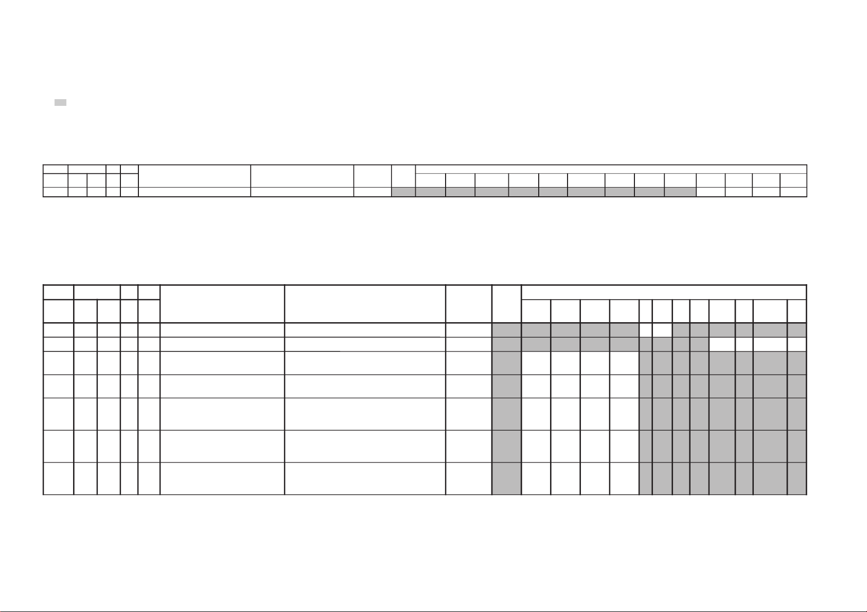
REVISION HISTORY
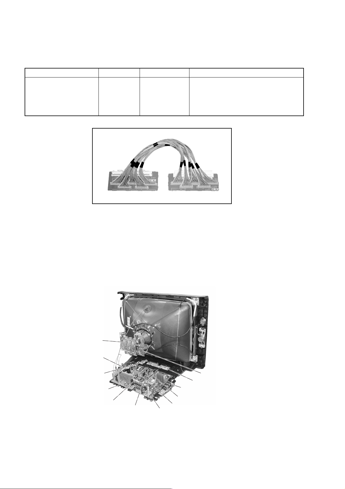
CX1
CHASSIS
MODEL
KV-DA34M61
KV-DA34M81
KV-DA34M81
NO. SUFFIX DATE SUPP / CORR DESCRIPTION
1 -01 2004/9 _ _ 1st Issue
PART NO. : 9-872-468-01
SERVICE MANUAL CX1
CHASSIS
MODEL COMMANDER DEST. CHASSIS NO.
KV-DA34M61 RM-W105 GE SCC-V25A-A
KV-DA34M81 RM-W105 Middle East SCC-V24A-A
KV-DA34M81 RM-W105 Saudi Arabia SCC-V22B-A
MODEL COMMANDER DEST. CHASSIS NO.
RM-W105
TRINITRON
®
COLOR TV

KV-DA34M61/M81
RM-W105
TABLE OF CONTENTS
Section Title Page
SELF DIAGNOSTIC FUNCTION..............................3
1. DISASSEMBLY
1-1. Rear Cover Removal................................................. 6
1-2. Speaker Removal ...................................................... 6
1-3. Chassis Assy Removal .............................................. 6
1.4. Service Position ........................................................ 6
1-5. Terminal Bracket Removal ....................................... 6
1-6. J Board Removal....................................................... 6
1-7. F1 Board Removal .................................................... 7
1-8. DL Board Removal ................................................... 7
1-9. BH1, BP and BC Boards Removal ........................... 7
1-10.H1 and H2 Boards Removal..................................... 7
1-11.A and D Boards Removal ......................................... 7
1-12.Picture Tube Removal............................................... 8
2. SERVICE JIG.......................................................... 10
3. CIRCUIT BOARDS LOCATION ............................. 10
4. ADVANCE OPERATION
4-1. "RESET" Function.................................................. 11
Section Title Page
7. DIAGRAMS
7-1. Block Diagram ........................................................ 65
7-2. Schematic Diagram Information ............................ 66
7-2-1. BC board Schematic Diagram ................... 67
7-2-2. BH1 board (Block 001) .............................69
7-2-3. BH1 board (Block 002).............................. 71
7-2-4. F1 board Schematic Diagram......................73
7-2-5. H1 board Schematic Diagram .................... 74
7-2-6. H2 board Schematic Diagram .................... 76
7-2-7. A Board (Block 001) .................................. 77
7-2-8. A Board (Block 002) .................................. 79
7-2-9. A Board (Block 003) .................................. 81
7-2-10.A Board (Block 004) .................................. 83
7-2-11. C board Schematic Diagram ...................... 84
7-2-12.D board (Block 001)................................... 86
7-2-13.D board (Block 002)................................... 88
7-2-14.DL board Schematic Diagram.................... 89
7-2-15.VM board (Block 001) ............................... 91
7-2-16.VM board (Block 002) ............................... 93
7-2-17.J board Schematic Diagram ....................... 94
7-3. Voltage Measurement and Waveform..................... 95
7-4. Printed Wiring Boards .......................................... 107
7-5. Semiconductors..................................................... 120
5. SET-UP ADJUSTMENTS
5-1. Beam Landing ......................................................... 12
5-2. Convergence Adjustment........................................ 13
5-3. Focus Adjustment.................................................... 15
5-4. Neck Assy Twist Adjustment.................................. 15
5-5. G2 (SCREEN) and White Balance Adjustment ..... 15
6. CIRCUIT ADJUSTMENTS
6-1. Adjustment With Commander ................................ 16
6-2. Adjustment Method ................................................ 17
6-3. Picture Quality Adjustments................................... 62
6-4. Sub Hue/Col Adjustment ........................................ 62
6-5. Deflection Adjustments .......................................... 62
6-6. A Board Adjustment After IC003 (MEMORY)
Replacement............................................................ 63
6-7. Picture Distortion Adjustment ................................ 64
8. EXPLODED VIEWS
8-1. Speaker Bracket .................................................... 122
8-2. Chassis................................................................... 124
9. ELECTRICAL PARTS LIST.................................. 125
OPERATING INSTRUCTIONS
CAUTION
SHORT CIRCUIT THE ANODE OF THE PICTURE TUBE AND
THE ANODE CAP TO THE METAL CHASSIS, CRT SHIELD,
OR CARBON P AINTED ON THE CRT, AFTER REMOVING THE
ANODE.
SAFETY-RELATED COMPONENT WARNING!!
COMPONENTS IDENTIFIED BY SHADING AND MARK ! ON
THE SCHEMATIC DIAGRAMS, EXPLODED VIEWS AND IN
THE PARTS LIST ARE CRITICAL TO SAFE OPERATION.
REPLACE THESE COMPONENTS WITH SONY PARTS
WHOSE PART NUMBERS APPEAR AS SHOWN IN THIS
MANUAL OR IN SUPPLEMENTS PUBLISHED BY SONY.
– 2 –

KV-DA34M61/M81
SELF DIAGNOSTIC FUNCTION
The units in this manual contain a self-diagnostic function. If an error occurs, the STANDBY (1) indicator will
automatically begin to flash.
The number of times the STANDBY (1) flashes translates to a probable source of the problem. If an error symptom
cannot be reproduced, the remote commander can be used to review the failure occurrence data stored in memory to
reveal past problems and how often these problems occur.
1. DIAGNOSTIC TEST INDICATORS
When an error occurs, the STANDBY (1 ) indicator will flash a number of times to indicate the possible cause of the
problem. If there is more than one error, the indicator will identify the first of the problem areas.
Result for all of the following diagnostic items are displayed on screen. No error has occured if the screen displays a
“0”.
RM-W105
Diagnostic
Item
Description
• Power does not
turn on
• +B overcurrent
(OCP)
• Horizontal
deflection failure
• +B overvoltage
(OVP)
• Vertical deflection
failure
• White balance
failure (no
PICTURE)
• 5V/9V Failure
• Micro reset
No. of times
STANDBY (1)
indicator flashes
Does not light
2 times
3 times
4 times
5 times
8 times
—
Self-diagnostic
display/Diagnostic
result
—
002:000 or
002:001~255
003:000 or
003:001~255
004:000 or
004:001~255
005:000 or
005:001~255
008:000 or
008:001~225
101:00 or
101:001~225
Probable
Cause
Location
• Power cord is not plugged
in.
• Fuse is burned out F1601
(F1 Board)
• H.OUT Q6802 is shor ted.
• C6831 is open circuit.
PS6606 open, PS6605
open.(D board)
• PH6602 faulty.
D6644 faulty, R6651 open.
• 10.5V is not supplied.
(D board)
• V.OUT IC6800 faulty
D6816 faulty
D6817 faulty
D6824 faulty
R6852 open
R6851 open (D board)
• G2 is improperly adjusted.
• CRT problem.
• Video OUT IC9001, 9002,
9003 are faulty. (C board)
• IC4301 (CXA2170Q)
(A board) is faulty.
• 5V Regulator (IC2601)
faulty.
• 9V Regulator (IC2600)
faulty.
• CRT Discharge (C Board)
• Static discharge
• External noise
Detected
Symptoms
• Power does not come on.
• No power is supplied to the
TV.
• AC power supply is faulty.
• Power does not come on.
• Load on power line is
shorted.
• H pulse output is too high.
• Power does not come on.
• Vertical deflection pulse is
stopped.
• Vertical size is too small.
• Vertical deflection stopped.
• No raster is generated.
• CRT cathode current
detection reference pulse
output is small.
• TV Blank
• No Raster
• Power is shut down shortly,
after this return back to
normal.
• Detect Micro latch up.
– 3 –
KV-DA34M61/M81
RM-W105
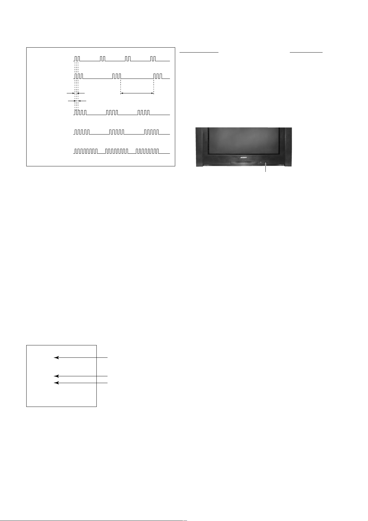
2. DISPLAY OF STANDBY (1) indicator FLASH COUNT
2 times
3 times
Lamp ON 0.3 sec.
Lamp OFF 0.3 sec.
Lamp OFF 3 sec.
Diagnostic Item Flash Count*
+B overcurrent,Horizontal Deflection F ailure 2 times
+B overvoltage 3 times
V deflection stop 4 times
White balance failure 5 times
5V/9V Failure 8 times
4 times
5 times
8 times
* One flash count is not used for self-diagnostic.
STANDBY (1) indicator
3. ST OPPING THE STANDBY (1) indicator FLASH
Turn off the power switch on the TV main unit or unplug the power cord from the outlet to stop the STANDBY (1)
indicator from flashing.
4. SELF-DIAGNOSTIC SCREEN DISPLAY
For errors with symptoms such as "power sometimes shuts off" or "screen sometimes goes off" that cannot be
confirmed, it is possible to bring up past occurence of failure on the screen for confirmation.
[To Bring Up Screen Test]
In standby mode, press buttons on the remote commander sequentially in rapid succession as shown below:
[display] / channel
5 / volume [-] / Power / TV
˘
Note that this differs from entering the service mode (volume [+]).
Self-Diagnostic screen display
SELF DIAGNOSTIC
002 : 000
003 : 000
004 : 000
005 : 001
008 : 002
101 : 000
Numeral "0" means that no fault has been detected.
Numeral "1" means a fault has been detected.
Numeral "2" means two faults have been detected.
– 4 –
KV-DA34M61/M81
5. HANDLING OF SELF-DIAGNOSTIC SCREEN DISPLAY
Since the diagnostic results displayed on the screen are not automatically cleared, always check the self-diagnostic
screen during repairs. When you have completed the repairs, clear the result display to "0".
Unless the result display is cleared to "0", the self-diagnostic function will not be able to detect subsequent faults after
completion of the repairs.
[Clearing the result display]
To clear the result display to "0", press buttons on the remote commander sequentially when the self-diagnostic screen
is displayed as shown below:
Channel 8 / "0"
[Quitting Self-diagnostic screen]
To quit the entire self-diagnostic screen, turn off the power switch on the remote commander or the main unit.
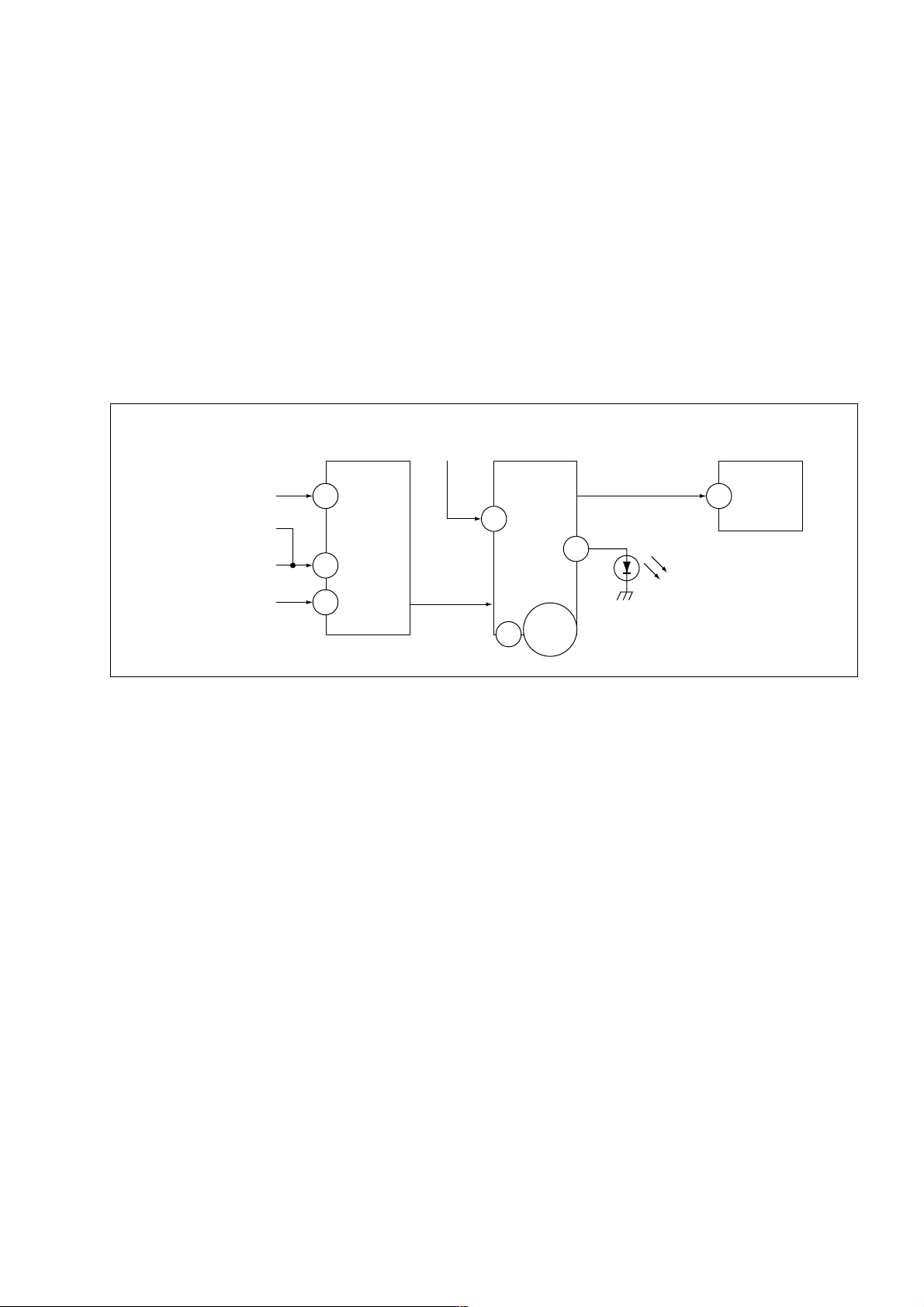
6. SELF-DIAGNOSTIC CIRCUIT
RM-W105
FROM
CRT (IK)
[OCP] Q6804, D6821
[H] D6808, D6809
[V] Q6808, R6910
IC4301
RGB JUNGLE
IK_IN
57
H PROT
56
V PROT
CXA2170AQ
OVP
SDA
IC001
SYSTEM
6
RED LED
5V
9V
14,47,82
84
IC004
MEMORY
SDA
7
524
[+B overcurrent OCP ] Occurs when an overcurrent on the +B(135) line is detected by
Q6804.
If Q6804 go to ON, the voltage to the pin57 of IC4301 go to "HIGH".
The unit will automatically turn off.
[High voltage protector of Horizontal Deflection] Occurs when an overvoltage of horizontal pulse is detected by
D6809.
If the voltage of anode D6809, Q6814 and D6808 goes to "High", the
voltage to pin57 of IC4301 go to "HIGH". The unit will automatically
turn off.
[+B overvoltage OVP ] Occurs when an overvoltage on the +B(135) line is detected by
D6635 and Q6611. If Q6611 go to ON, the voltage to pin6 of IC001
go to "HIGH". The unit will automatically turn off.
[Vertical deflection failure] Occurs when an absence of the vertical deflection pulse is detected
by Q6808 and R6910. Shut down the power supply.
[White balance failure] If the RGB levels do not balance or become low level within 5
seconds. This error will be detected by IC4301.
TV will stay on, but there will be no picture.
[Micro Fails to Start-up] Occurs when 5V/9V is not supplied to micon (IC001). No Raster will
be detected or No Picture.
– 5 –
KV-DA34M61/M81
RM-W105
SECTION 1
DISASSEMBLY
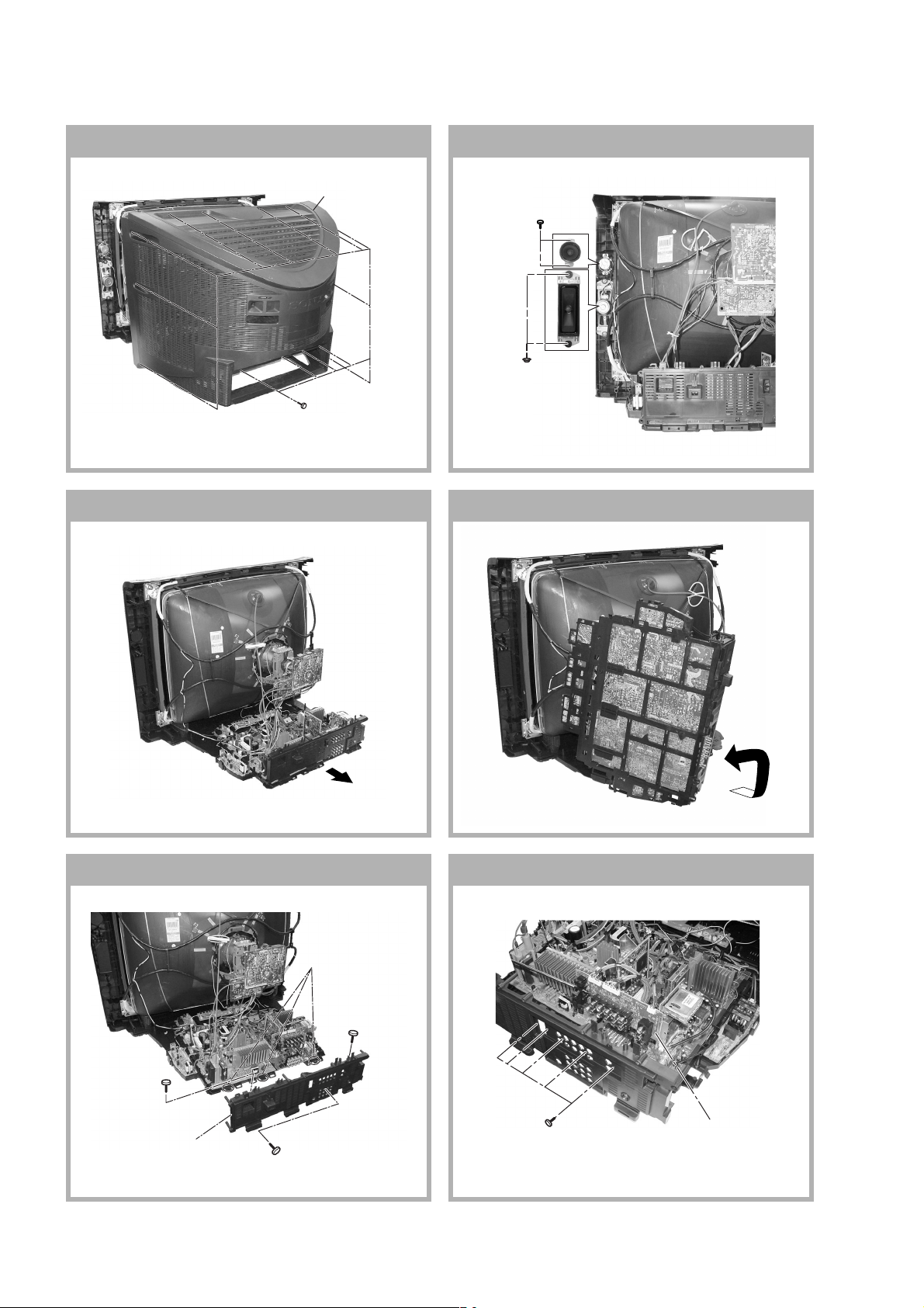
1-1. REAR COVER REMOVAL
2 Rear cover
1 Fourteen screws
(+BVTP 4 × 16)
1-2. SPEAKER REMOVAL
1 Two screws
(+BVTP 4 × 16)
2 Two screws
(Washer Head)
(+P4 × 16)
1-3. CHASSIS ASSY REMOVAL 1-4. SERVICE POSITION
1-5. TERMINAL BRACKET REMOVAL 1-6. J BOARD REMOVAL
5 Three Hooks
2 One Screw
(+BVTP 3 × 12)
1 One screw
(+BVTP 3 × 12)
4 Terminal Bracket
3 One screw
(+BVTP 4 × 16)
1 Five screws
(+BVTP 3 × 12)
– 6 –
2 J Board
KV-DA34M61/M81
RM-W105
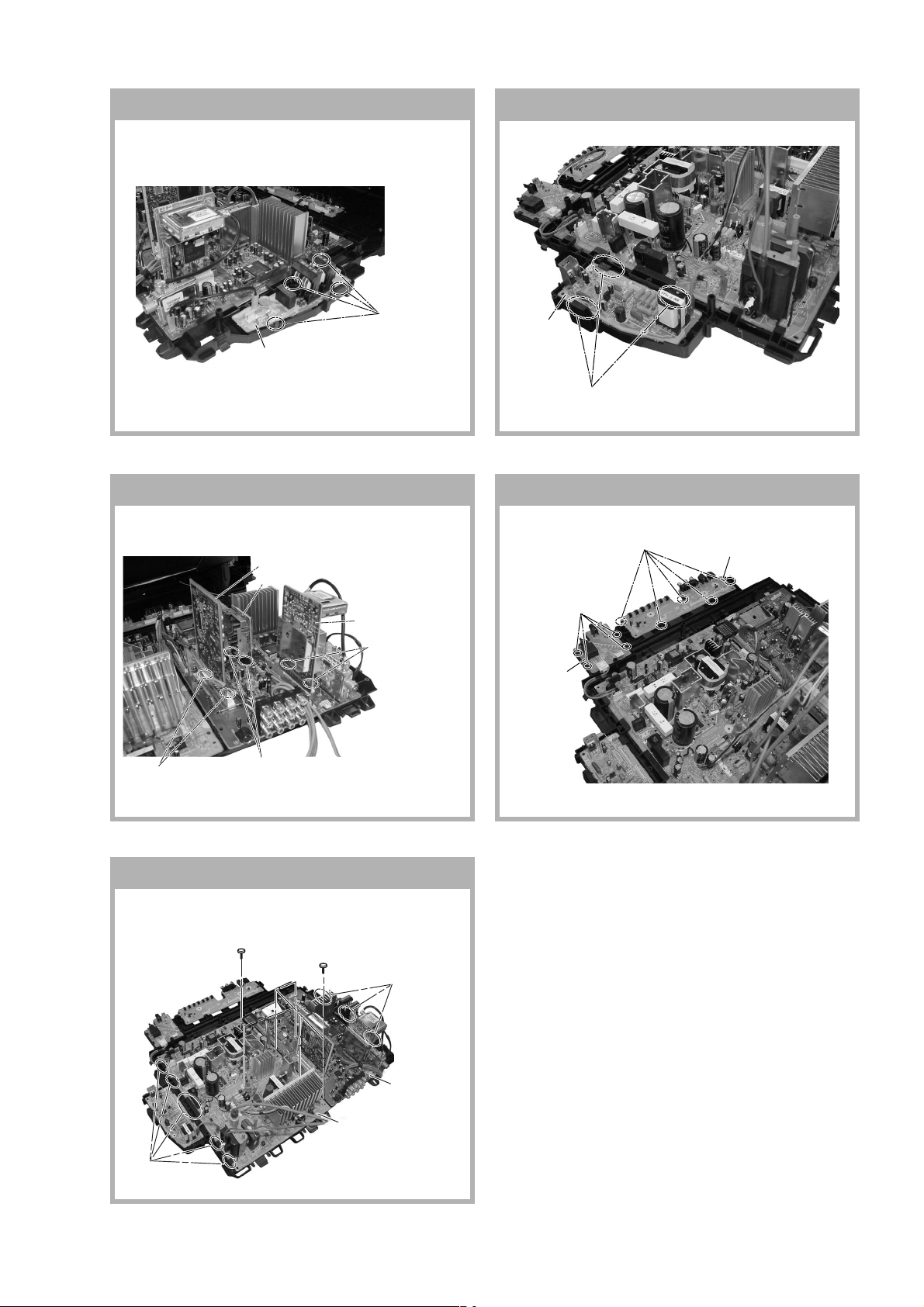
1-7. F1 BOARD REMOVAL
1 Four Hook
2 F1 Board
1-8. DL BOARD REMOVAL
2
DL Board
1 Three Hooks
1-9. BH1, BP AND BC BOARDS REMOVAL 1-10. H1 AND H2 BOARDS REMOVAL
2 BH1 Board
4 BC Board
6 BP Board
(Not used for these models)
5 Two
Hooks
1 Five Hooks
3 Four
Hooks
4 H2 Board
2 H1 Board
1 Two Hooks
3 Two Hooks
1-11. A AND D BOARDS REMOVAL
3 One screw
(washer head)
(+P 3 × 12)
2 Five Hooks
1 Five screws
(+BVTP 3 × 12)
5 Three Hooks
4 D Board
6 A Board
– 7 –
KV-DA34M61/M81
RM-W105
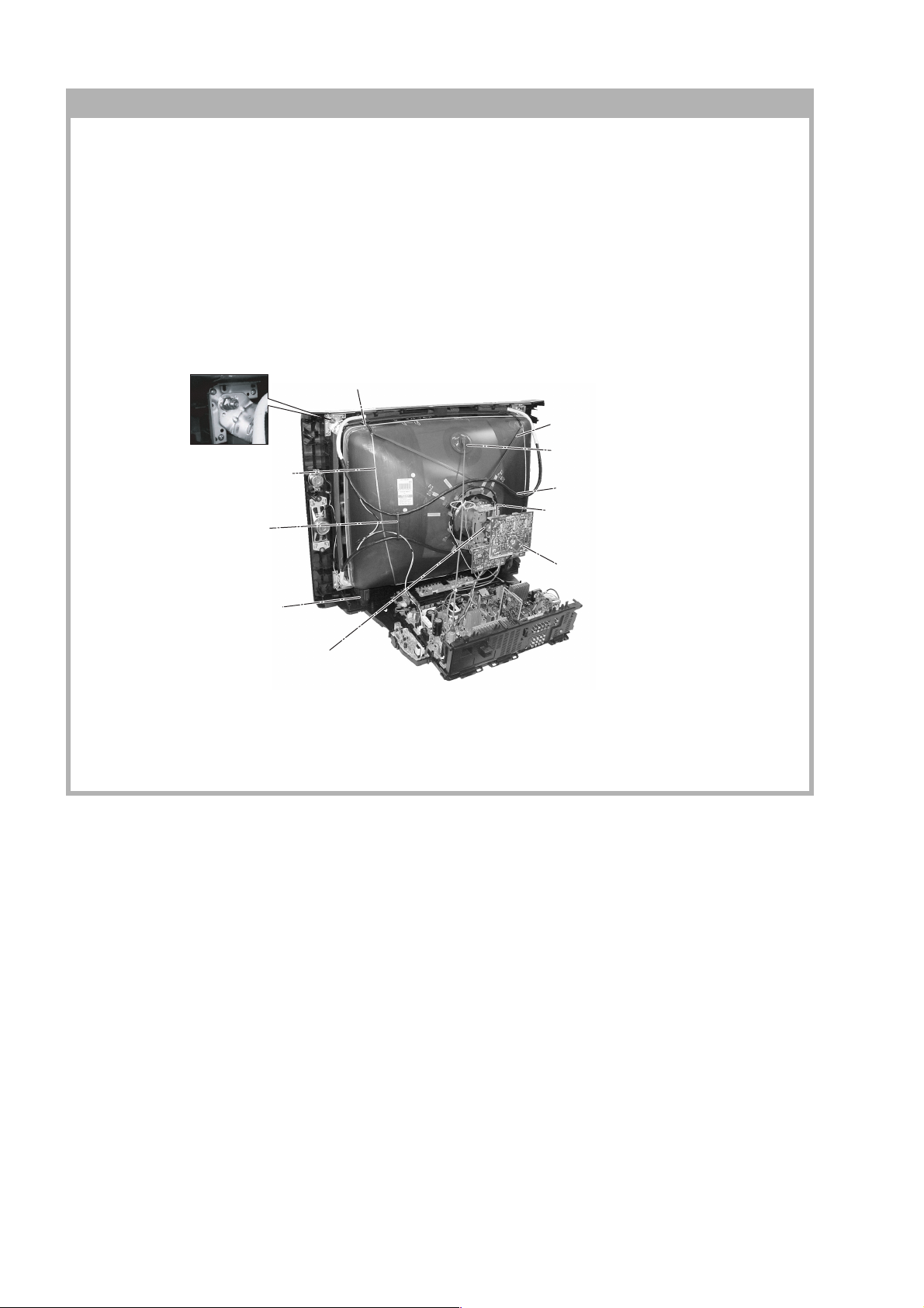
1-12. PICTURE TUBE REMOV AL
Note:
• Please make sure the TV set is not in standing position before removing necessary CRT support located on
bottom right and left.
• When removing the Nut Locking: first make sure to hold the Nut special CR T with a spanner while opening the Nut
Locking using a torque driver. Then proceed to remove the Nut special CRT using a torque driver.
1)Removal the Rear Cover.
2)Unplug all interconnecting leads from the Deflection Yoke, Neck Assy, Degaussing Coils and CRT grounding strap.
Remove Chassis Assy.
3)Place the TV set with the CRT face down on a cushion (jig).
qf Screw, Tapping 7 +
Crown Washer
9 Earth Coating Assy
5 Holder, DGC
Removal (x2)
8 Spring Tension(4)
Removal
6 Band, DGC Removal
4 Anode Cap Removal
7 Degaussing Coil
qa Loosen the Neck Assembly
fixing screw and remove Neck Assy &
VM board
qd Support CRT
Removal (x2)
qs Loosen the Deflection Yoke
fixing screw and remove
q; C Board Removal
– 8 –
KV-DA34M61/M81
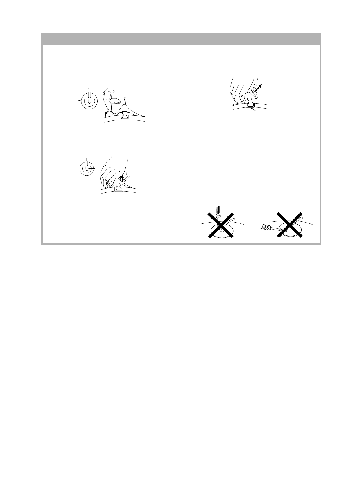
• REMOVAL OF ANODE-CAP
Note:
• After removing the anode, short circuit the anode of the picture tube and the anode cap to the metal chassis, CRT
shield or carbon paint on the CRT.
• REMOVING PROCEDURES
c
a
RM-W105
a
1 Turn up one side of the rubber cap in the direction
indicated by the arrow a.
b
b
2 Using a thumb pull up the rubber cap firmly in the direc-
tion indicated by the arrow b.
Anode Button
3 When one side of the rubber cap is separated from the
anode button, the anode-cap can be remo ved by
turning up the rubber cap and pulling it up in the
direction of the arrow c.
• HOW TO HANDLE AN ANODE-CAP
1 Do not damage the surface of anode-caps with
sharp shaped objects.
2 Do not press the rubber too hard so as not to
damage the inside of anode-cap.
A metal fitting called the shatter-hook terminal is
built into the rubber.
3 Do not turn the foot of rubber over too hard.
The shatter-hook terminal will stick out or damage
the rubber.
– 9 –
KV-DA34M61/M81
RM-W105
2-1. JIGS REQUIRED FOR SERVICING
DESCRIPTION QUANTITY PART NO. REMARK
TOOL(7P,8P),SERVICE 1 J-2509-400-D For A to BC board extension
TOOL(30P),SERVICE 1 J-2509-400-E For A to BP board extension
TOOL(50P-A),SERVICE 1 3-702-765-01 For A to BH1 board extension
SECTION 2
SERVICE JIG
(not used for these models)
SAMPLE
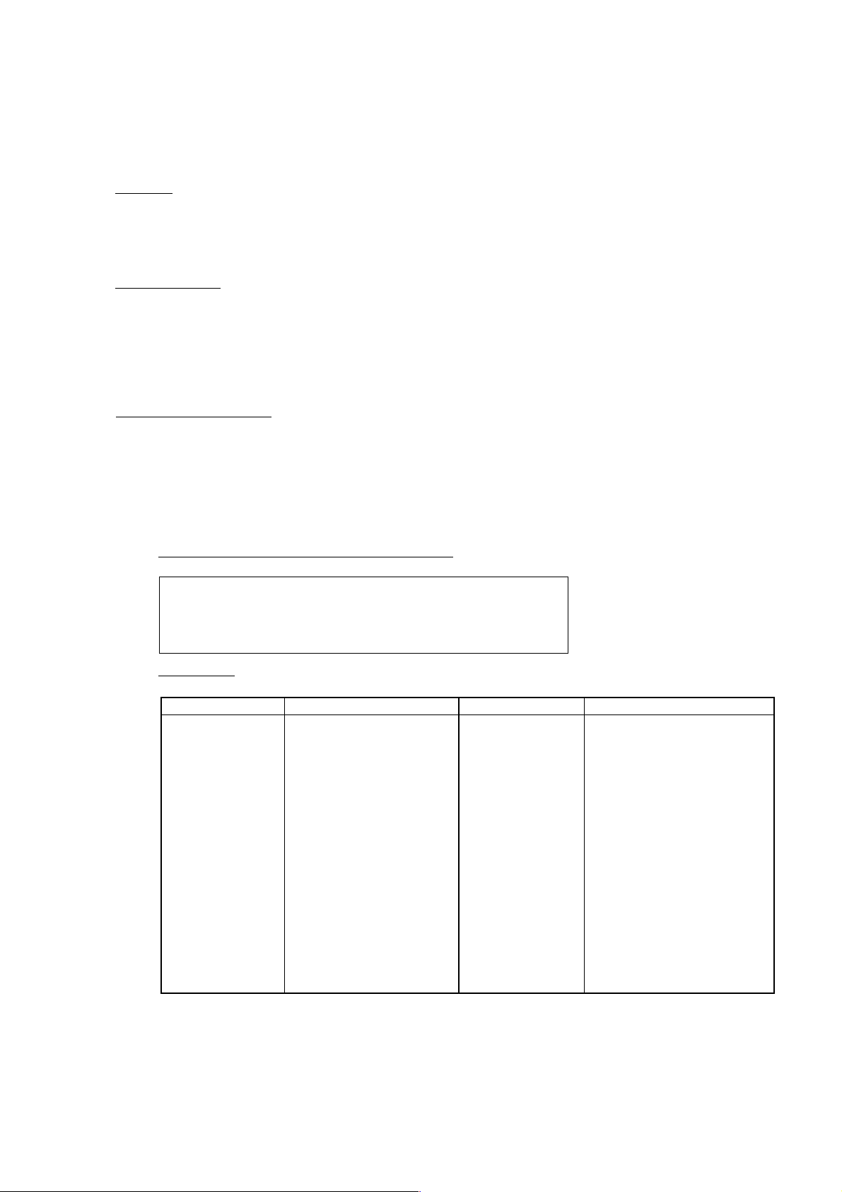
C Board
DL Board
H2 Board
D Board
BH1 Board
SECTION 3
CIRCUIT BOARDS LOCATION
VM Board
H1 Board
F1 Board
BC Board
J Board
A Board
BP Board (not used for these models)
– 10 –
KV-DA34M61/M81
SECTION 4
ADVANCE OPERATION
4-1. "RESET" FUNCTION
1. Purpose
If a customer faces some setting problem that cannot be solved, using the "RESET" function some items
will be reset to its original setting (shipping condition)
2. How to Operate
There are 2 ways to access to the "RESET" Function:-
a) By pressing "RESET" button on the Remote Commander.
b) By pressing "MENU" button on the Front Key Input and hold it down for 5 seconds.
(Note : only available for KV-DAXXNXX and KV-DAXXKXX.)
3. Sequence of Operation
RM-W105
Sequential to the resetting operation, TV set would shut down once and automatically turn on again.
The power-off duration is expected to be about 500msec. Initial Setup Menu is displayed.
As a result, some items will be reset to an initial condition (shipment condition) where else some other
remains at the last selection by user.
Items that remains at the last selection by user
Program No., Picture Position (includes Picture Rotation and
Picture V-Position), OSD Language, Fine Tuning,
TV System, Skip, Program label, Program Sorting, Video
label, Program block (NTSC model)
Reset Items
Category Default Category Default
Video input RF user last setting
Volume 25
DRC-MF DRC1050
Picture mode DYNAMIC
3D Intelligent Picture ON
Sound mode DYNAMIC
Intelligent volume OFF
Surround OFF
Wide Mode 4:3
Auto Wide ON
Twin OFF
Program Index OFF
*Program Block Reset to particular channel to
unblock
WEGA Theatre Setup
Direct Input Video 1
Speaker Main
Game Mode OFF (Video) *Not available in RF
mode
Color System Reset to Auto at the CH, others
keep user setting
ECO Mode OFF
Wide Mode Wide Zoom
Auto Wide ON
4:3 Default Wide Zoom
V Center 00
V Size 00
Picture Mode RF user last setting
Mute OFF
OSD Display Setting OFF
Main Volume 25
Center-in Volume 25
(Remote Button)
Center Speaker Main or Center in (No menu display)
(Under WEGA Main or Center in (selected only
Theatre Setup Menu) when WTM turns on)
Initial Setup Menu Reactive / ON
Twin size Center
*= Reset only during watching time
- For multi model only
- Not reset for NTSC model
– 11 –
KV-DA34M61/M81
RM-W105
SECTION 5
SET-UP ADJUSTMENTS
• The following adjustments should be made when a complete
realignment is required or a new picture tube is installed.
• These adjustments should be performed with rated power
supply voltage unless otherwise noted.
Perform the adjustments in the following order :
1. Beam Landing
2. Convergence
3. Focus
4. White Balance
Controls and switches should be set as follows unless otherwise
noted:
PICTURE control........................................................... normal
BRIGHTNESS control................................................... normal
................................................................................................................................................................................................................................
Note : Test Equipment Required.
1. Color-bar/Pattern Generator
2. Degausser
3. Oscilloscope
Preparation :
• In order to reduce the influence of geomagnetism on the set's
picture tube, face it east or west.
• Switch on the set's power and degauss with the degausser.
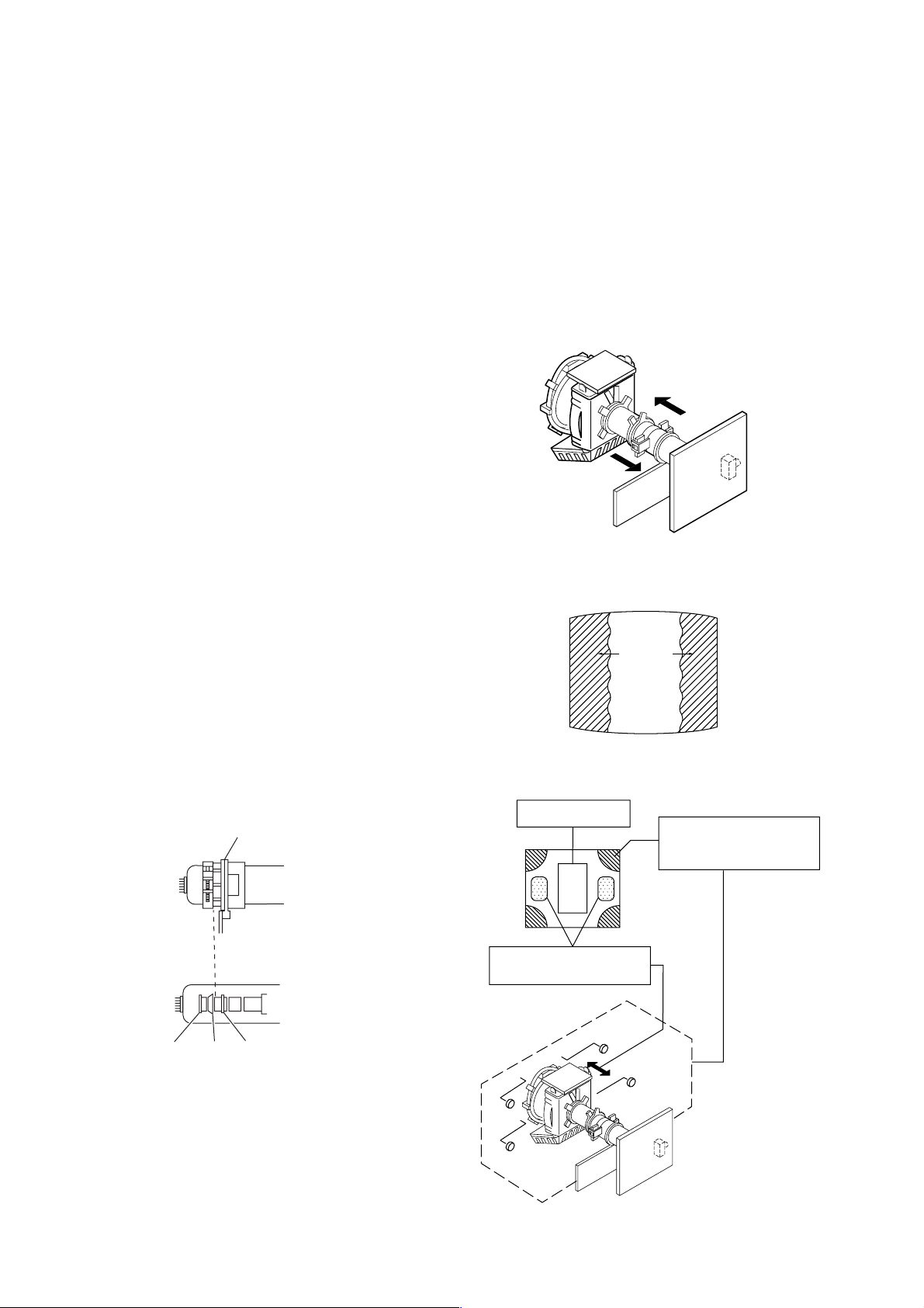
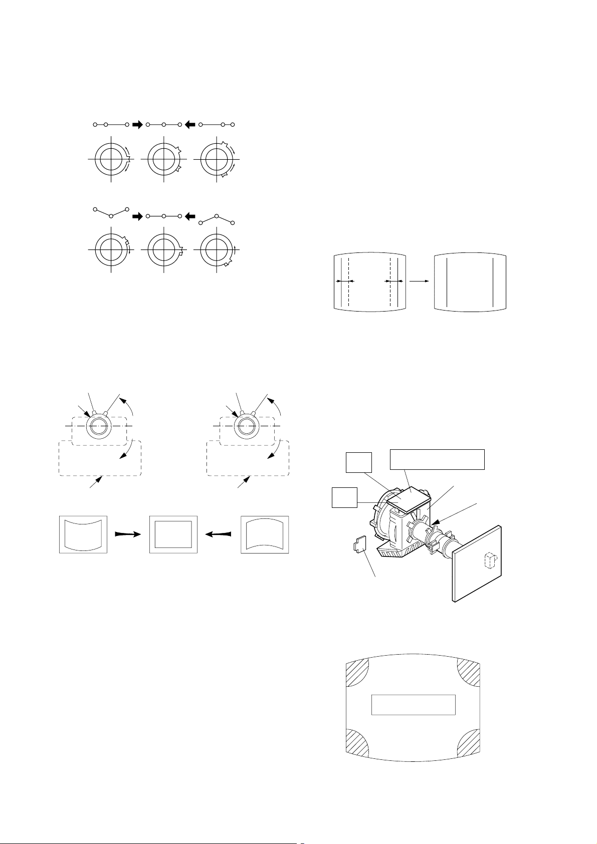
5-1. BEAM LANDING
1. Input a white signal with the pattern generator.
Picture mode : Dynamic
2. Position neck assy as shown in Fig 5-1.
3. Set the pattern generator raster signal to a green raster.
4. Move the deflection yoke to the rear and adjust with the
purity control so that the green is at the center and the blue
and the red take up equally sized areas on each side.
(See Figures 5-1 through 5-3.)
5. Move the deflection yoke forward and adjust so that the
entire screen is green. (See Figure 5-2.)
6. Switch the raster signal to blue, then to red and verify the
condition.
7. When the position of the deflection yoke has been decided,
fasten the deflection yoke with the screws and DY spacers.
8. If the beam does not land correctly in all the corners, use a
magnet to adjust it.
(See Figure 5-4.)
Fig. 5-2
Blue
Red
Green
Fig. 5-3
Neck assy
Align the edge of
the neck assy with
the edge of the G3 grid.
G2G1 G3
Fig. 5-1
Purity control
corrects this area.
b
c
Deflection yoke positioning
corrects these areas.
a
d
a
d
b
Fig. 5-4
Disk magnets or rotatable
disk magnets correct these
areas (a-d).
c
– 12 –
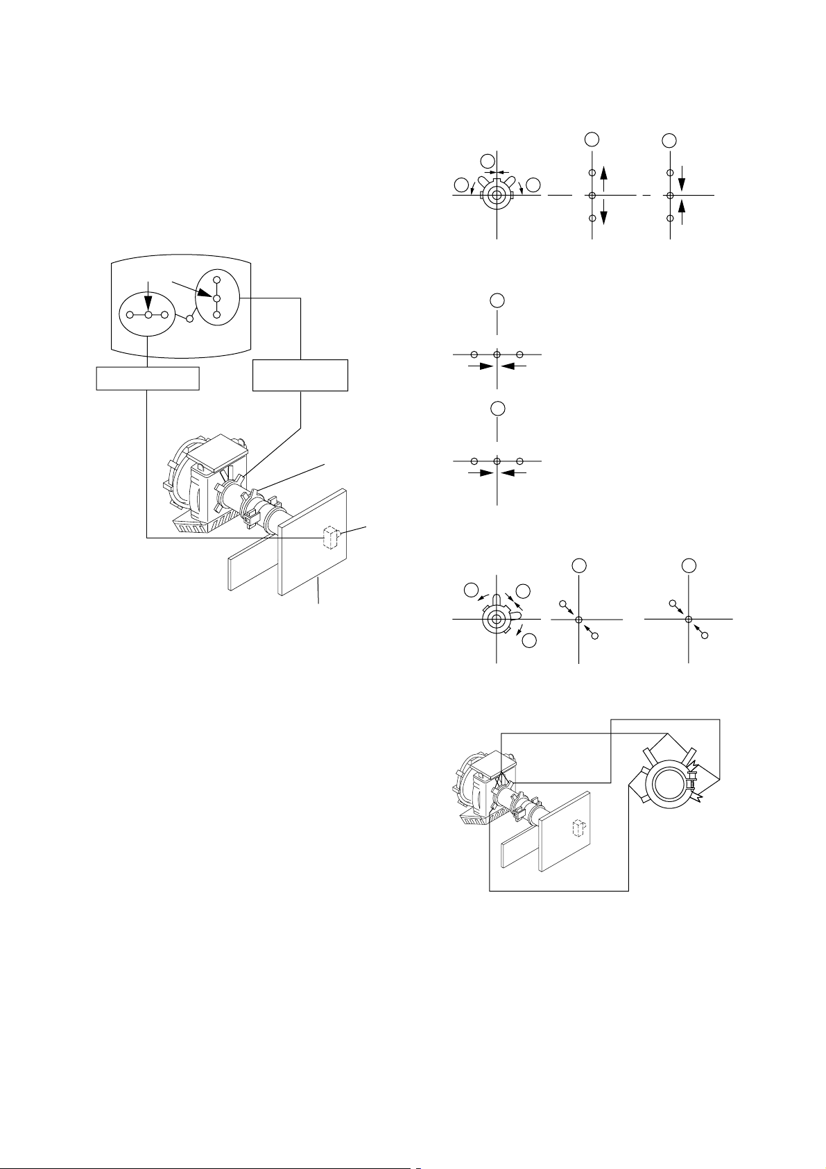
5-2. CONVERGENCE ADJUSTMENT
Preparation :
• Before starting this adjustment, adjust the focus, horizontal
size and vertical size.
• Receive cross hatch/dot pattern and set picture mode to
"STANDARD".
(1) Horizontal and Vertical Static Convergence
1 V. STAT
b b
KV-DA34M61/M81
RM-W105
a
a
B
G
R
b
B
G
R
Center dot
R G B
H. STAT VR
R
G
B
V. STAT
Magnet
Y magnet
RV702
H. STAT
C Board
1. (Moving horizontally), adjust the H.STAT control so that the
red, green and blue dots are on top of each other at the center
of the screen.
2. (Moving vertically), adjust the V.STAT magnet so that the
red, green and blue dots are on top of each other at the center
of the screen.
3. Adjust Horizontal Trapezoid with “DEF1 005 HTPZ” in
Service Mode to make H-Trapezoid distortion best.
4. If the H.STAT variable resistor cannot bring the red, green
and blue dots together at the center of the screen, adjust the
horizontal convergence with the H.STAT variable resistor and
the V.STAT magnet in the manner given below.
(In this case, the H.STAT variable resistor and the V.STAT
magnet influence each other, so be sure to perform
adjustments while tracking.)
2 H. STAT VR
a
RGGBB
b
3
b
R
a
a
R
b
Purity
B
BMC (Hexapole)
V.STAT
b
B
GG
R
– 13 –
KV-DA34M61/M81
RM-W105
4 BMC (Hexapole) Magnet.
If the red, green and blue dots are not balanced or aligned,
then use the BMC magnet to adjust in the manner described
below.
RG B R G B R GB
RB
G
RG
GB
RB
5 Y separation axis correction magnet adjustment.
1. Receive the cross-hatch signal and adjust [PICTURE] to
[MIN] and [BRIGHTNESS] to [STANDARD].
2. Adjust the Y separation axis correction magnet on the neck
assembly so that the horizontal lines at the top and bottom of
the screen are straight.
Neck assy
Blue
Red
Neck assy
Blue
Red
(2) Dynamic Convergence Adjustment
Preparation:
• Before starting this adjustment, adjust the horizontal static
convergence and the vertical static convergence.
• Set the PICTURE and BRIGHTNESS to normal.
1. Adjust TLH. (TLH convergence piece)
1 Receive the dot/hatch pattern signal and adjust picture quality
by the menu.
2 Correct horizontal mis-convergence of red and blue of both
sides on the X axis.
When red is outside insert TLH convergence piece to right
side (TLH +) views from DY neck. And when blue is outside,
insert it to left side (TLH –) and take both sides.
R
(B)B(R)
(R)
B
TLH +
R
(B)
TLH -
2. Adjust XCV core.
To able to become balance of XCV on the X axis well.
3. Adjust TL V.
Correct the vertical mis-convergence of red and blue of
vertically sides on the Y axis.
4. Adjust YCH.
Adjust horizontal mis-convergence of red and blue of
vertically sides on the Y axis. Mentioned above steps 2 to 4
are adjusting respectively perform minuteness tracking.
Note
1. The Red and Blue magnets should be equally far from the
horizontal center line.
2. Do not separate the Red and Blue magnets too far.
(Less than 8 mm)
(VR2)
YCH
(VR3)
TLV2
TLH Plate
(VR1)
TLV1 (no need to adjust)
(3) Screen-corner Convergence
ba
a-d : screen-corner
misconvergence
cd
DY pocket
(XCV)
– 14 –
KV-DA34M61/M81
RM-W105
Fix a Permalloy assy corresponding to the
misconverged areas.
a
d
Permalloy assembly
b
c
5-3. FOCUS ADJUSTMENT
Note
Focus adjustment should be completed before W/B adjustment.
1. Receive digital monoscope pattern.
2. Set Picture mode to "STANDARD".
3. Adjust FOCUS VR so that the center of the screen becomes
just focus.
4. Change the receiving signal to white pattern and blue back.
5. Confirm MAGENTA RING is not noticeable. In case
MAGENTA RING is obvious, adjust FOCUS VR to balance
between MAGENTA RING and FOCUS adjustment.
5-4. NECK ASSY TWIST ADJUSTMENT
1. Receive dot/hatch pattern DRC-MF, DRC1250, DYNAMIC.
2. Turn FOCUS VR fully counter-clockwise.
3. Confirm the dot shape at the screen center. (Fig. 5-4)
4. Resume FOCUS VR.
Note
In case of turning NECK ASSY, loosen the screw 3 turns. Do not
move the position.
OK
Turn NECK ASSY clockwise.
Turn NECK ASSY counter clockwise.
Fig. 5-4
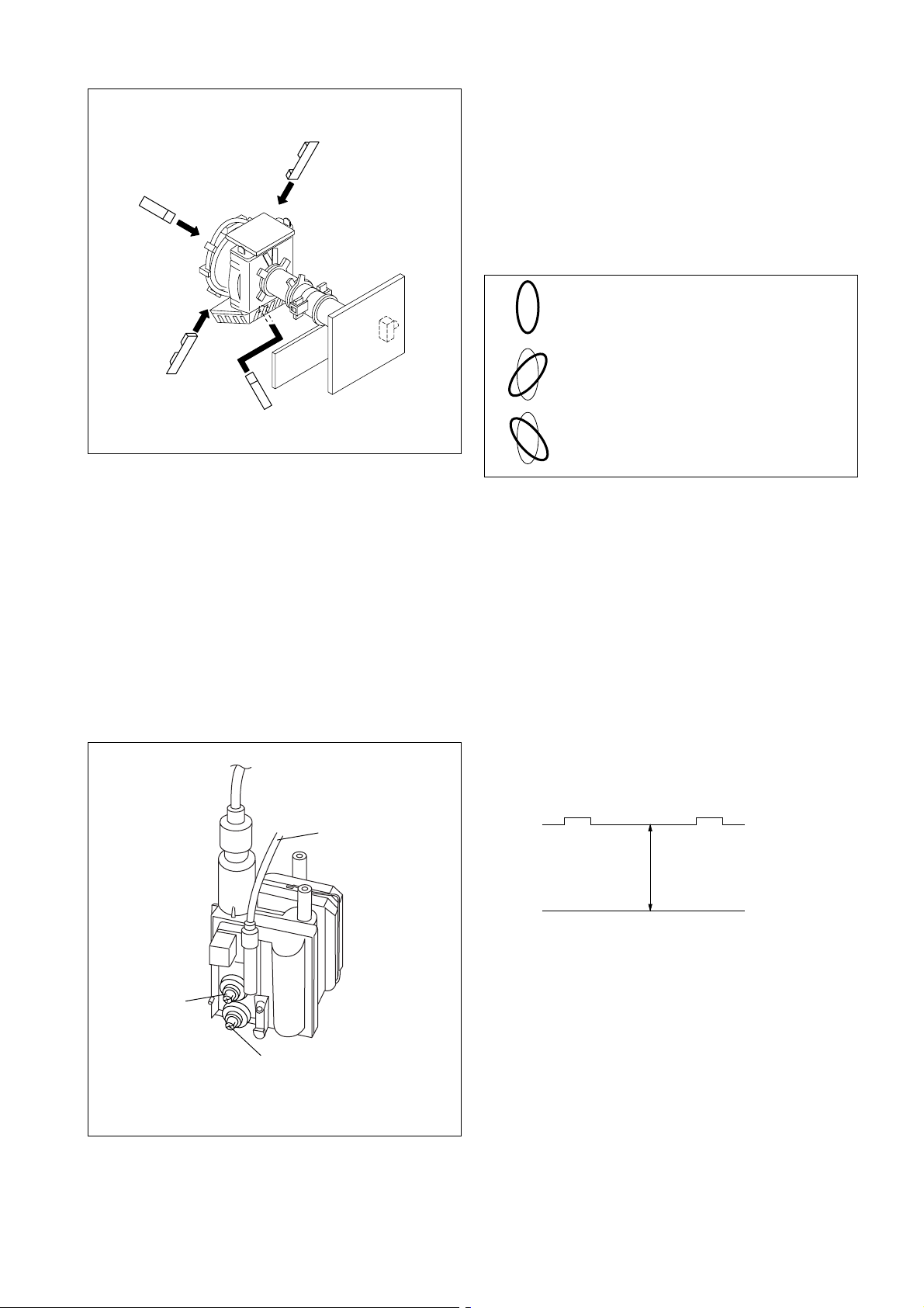
5-5. G2 (SCREEN) AND WHITE BALANCE
ADJUSTMENT
1. G2 (SCREEN) ADJUSTMENT
1. Set the PICTURE and BRIGHTNESS to normal.
2. Put to any signal mode.
3. Connect R, G and B of the C board cathode to the
oscilloscope.
4. Adjust BRIGHTNESS to obtain the cathode voltage to the
value below.
5. Whilst watching the picture, adjust the screen VR [RV9002]
located on the Flyback Transformer to the point just before
the retrace lines disappear (to the point before cut-off).
Lead Assy,
Focus
Focus
G2
FL YB A CK TRANSFORMER (T6803)
170v ± 2 (VDC)
0 V
2. WHITE BALANCE ADJUSTMENT
(Highlight Condition)
1. Set Picture to Dynamic mode.
2. Go to Service mode and adjust SADJ "COL" from 60 to 00.
3. Fix WHBL "RDRV" to 41.
4. Fix WHBL "RCUT" to 31.
5. Adjust "GDRV" and "BDRV" for highlight.
6. Adjust "GCUT" and "BCUT" for cut-off.
(Cut-off Condition)
1. Set Picture to Dynamic mode.
2. Adjust SADJ "COL" from 00 to 100.
3. Adjust "CBOF" and "CROF" for cut-off.
Once the above adjustments have been set, change back the
SADJ "COL" data to 60 (original condition).
– 15 –
KV-DA34M61/M81
RM-W105
SECTION 6
CIRCUIT ADJUSTMENTS
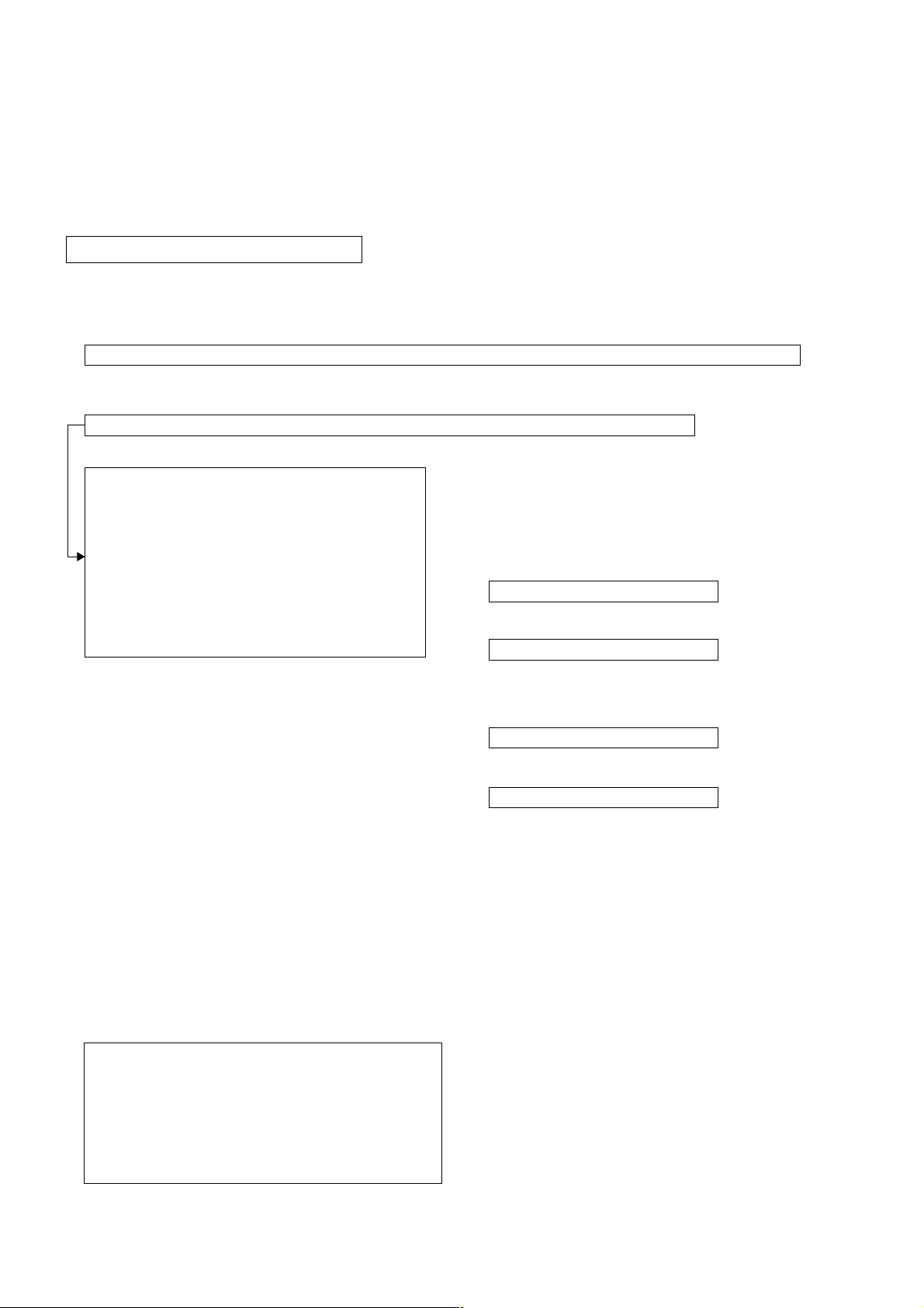
6-1. ADJUSTMENTS WITH COMMANDER
Service adjustments to this model can be performed using the supplied remote commander RM-W105.
a. ENTERING SERVICE MODE
With the unit on standby
t [DISPLAY] t 5 t [VOL $+% ] t [POWER]
This operation sequence puts the unit into service mode.
The screen display is as below:
Category in decimal Item name in decimal NG Command Frequency Video Input Name
WHBL 000 BKOR 000 x SERVICE 50 S VIDEO 1
Item no. Service data NVM Service Field Channel no./
Release ID Version in binary for factory Color System (decimal)
CGA01 0.16M 0000 0000 FF FF NTSC3 00100
S_ _ : for Sony
A_ _ : for AIWA
L_ _ : BX1L Full
B_ _ : BX1L Basic
D_ _ : DVD Combo
C_ _ : CX1
Z_ _ :Sound Special
_ _ _01 : Serial no. of the M/P release for each destination
_ _ _10 ~: use for FY04
_ _ _SB : Sub Hercules
Software Service data Reserved Power On Time
For BP Board version; and PF Engine Version;
Category and release ID will be different. The rest
are the same.
BP Board version
item no. item
Category in decimal name
SUBP 000 10XH
software
release ID version
CBP00 0.06
PF Engine version
item no. item
Category in decimal name
9090 000
software
release ID version
PF0018M
b. METHOD OF CANCELLATION FROM SERVICE MODE
Set the standby condition (Press [POWER] button on the commander), then press [POWER] button again, hereupon it becomes TV
mode.
c. METHOD OF WRITE INTO MEMORY
1. Set to Service Mode.
2. Press 1 (UP) and 4 (DOWN), to select the adjustment item.
3. Change item by pressing 3, 6.
4. Press [MUTING] button to indicate WRITE on the screen.
5. Press - button to write into memory.
1, 4 Select the adjustment item.
r
3, 6 Raise/lower the data value.
r
[MUTING] Writes.
r
- Executes the writing.
– 16 –
KV-DA34M61/M81
d. MEMORY WRITE CONFIRMATION METHOD
1. After adjustment, pull out the plug from AC outlet, and then plug into AC outlet again.
2. Turn the power switch ON and set to Service Mode.
3. Call the adjusted items again to confirm adjustments were made.
e. OTHER FUNCTION VIA REMOTE COMMANDER
7, - All the data becomes the values in memory.
8, - All user control goes to the standard state.
Display , - Service data initialization (Be sure not to use usually.)
2, 5 Select Device or Category
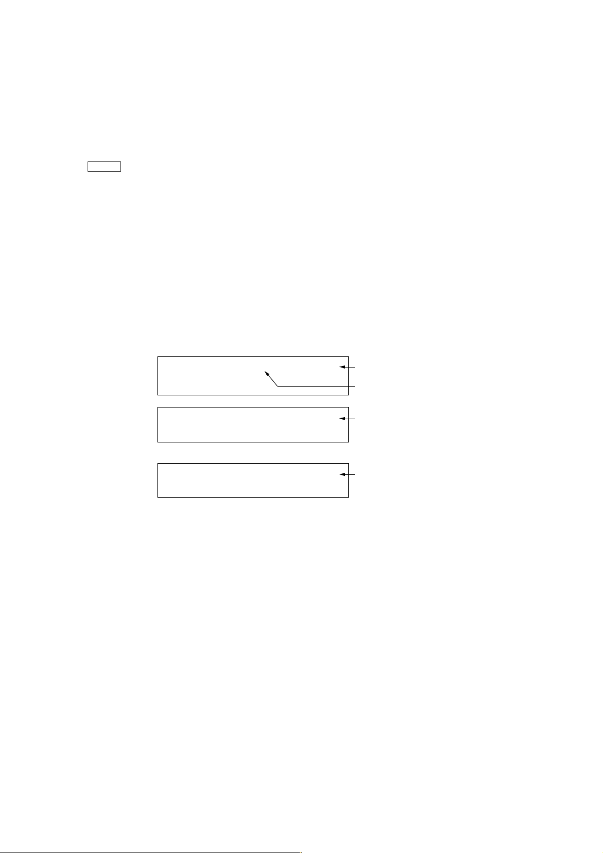
6-2. ADJUSTMENT METHOD
Item Number 000 BKOR
This explanation uses Black Level Offset as an example.
1. Select "000 BKOR" with the 1 and 4 buttons, or 2 and 5.
2. Raise/lower the data with the 3 and 6 buttons.
3. Select the optimum state. (The standard is IF for PAL reception.)
4. Write with the [MUTING] button. (The display changes to WRITE.)
5. Execute the writing with the - button. (The WRITE display will be changed to red color while excuting, and back to
SERVICE.)
Example on screen display :-
RM-W105
WHBL 000
CGA01
WHBL 000
CGA01
WHBL 000
CGA01
0.16M
0.16M
0.16M
Write with [MUTING]
Write executed with
000 50BKOR
SERVICE
0000 FF FF PAL 001220000
000 50BKOR
0000 FF FF PAL 001220000
000 50BKOR
0000 FF FF PAL 001220000
WRITE
WRITE
GREEN
Adjusted with 3
and 6 buttons.
GREEN
RED
The WRITE display
then the display
returns to green
SERVICE.
Use the same method for all Items. Use 1 and 4 to select the adjustment item, use 3 and 6 to adjust, write with
[MUTING], then execute the write with -.
Note : 1. In [WRITE], the data for all items are written into memor y together.
2. For adjustment items that have different standard data between 50Hz or 60Hz, be sure to use the respective
input signal after adjustment.
– 17 –
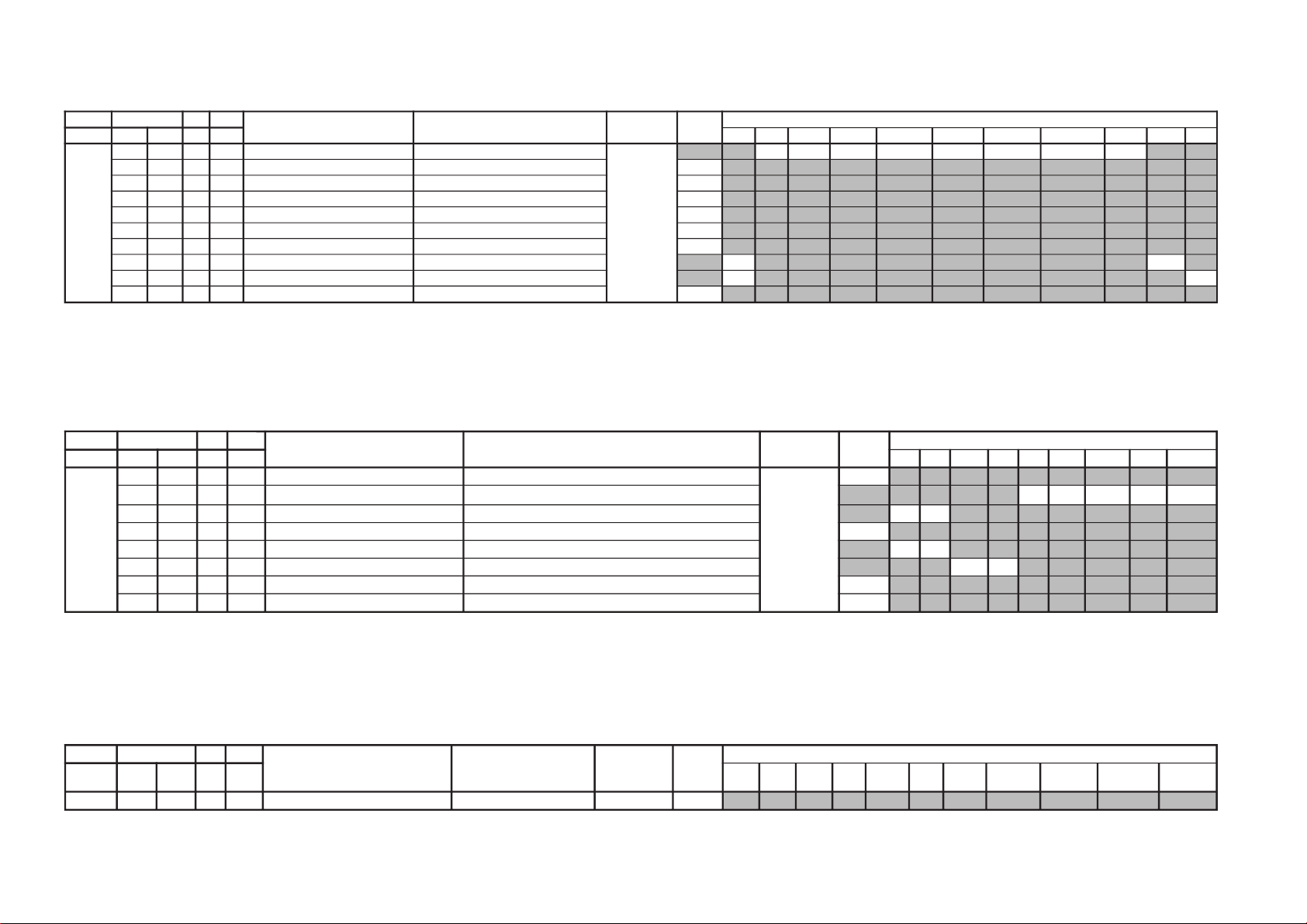
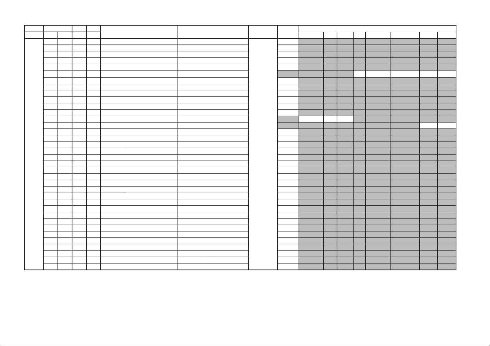
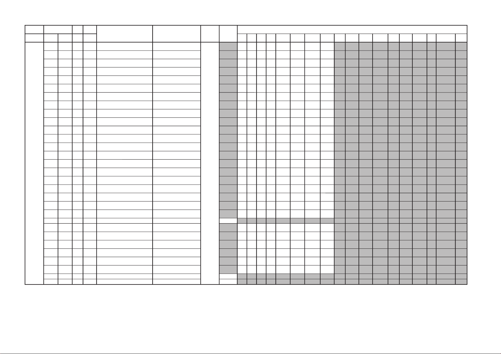
Adjustment Item Table (Main Micon)
JVTytilanoitcnuF.tinIegnaRnoitcnuFetoN&elbaTemaNeciveDnommoC )deliateD(eulaVlaitinI
yrogetaC.oNemaNceDceD
pmeTloC
)rehtoHGIH(
pmeTloC
)rehtoWOL(
pmeTloC
)rehtoMRON(
pmeTloC
)VUYHGIH(
pmeTloC
)VUYWOL(
pmeTloC
)VUYLAMRON(
pmeTloC
)BGRHGIH(
pmeTloC
)BGRWOL(
pmeTloC
)BGRMRON(
0edomciP1edomciP2edomciP3edomciP
LBHW000PBW
000300)woL:3,2,lamroN:1,hgiH:0(gnitteSpmeTroloC
edoMerutciP
00102010
JVTytilanoitcnuF.tinIegnaRnoitcnuFetoN&elbaTemaNeciveDnommoC )deliateD(eulaVlaitinI
yrogetaC.oNemaNceDceD
edomciP
0
edomciP
1
edomciP
2
edomciP
3
VToediVVT
ediW
oediV
ediW
lamroN
)3:4(
DHxednI/niwT
paP/
rehtO
JDAS000EUHS700510euH-buS oediV/VT
2090
100FOIP000700)%57(ocE*02/)atad-02(*erutciP(tesffOerutciP REHTO/ITLUM/LAMRON/SMenignEFP
45 7 0
200CIP130721;)dilavni(001>,)dilav(001-0:AG[lortnoCerutciP
])dilavni(6tiberongi;)dilav(36-0:srehtO
)ataDteseRresU=lanosreP:AG(ledoMerutciP
001080605
300LOC130721;)dilavni(001>,)dilav(001-0:AG[lortnoCroloC
])dilavni(6tiberongi;)dilav(36-0:srehtO
)ataDteseRresU=lanosreP:AG(ledoMerutciP
06060505
400TRB130721,)dilav(001-0:AG[lortnoCssenthgirB
tiberongi;)dilav(36-0:srehtO;)dilavni(001>
])dilavni(6
)ataDteseRresU=lanosreP:AG(ledoMerutciP
34050505
500EUH130721;)dilavni(001>,)dilav(001-0:AG[lortnoCeuH
otdneS*(])dilavni(6tiberongi;)dilav(36-0:srehtO
)ledomSUhtiw)0-5(hE1#TNIT
)ataDteseRresU=lanosreP:AG(ledoMerutciP
05050505
600PHS130721,)dilav(001-0:AG[lortnoCssenprahS
tiberongi;)dilav(36-0:srehtO;)dilavni(001>
])dilavni(6
)ataDteseRresU=lanosreP:AG(ledoMerutciP
05050505
NOTE
a) In the initial value (detailed) colomn, the data after the slash mark ("/") refers to NTSC model data.
No("/") means data is common for Multi and NTSC model.
b) Item remarked "*" and "**", please refer page xx~xx for the data.
c)
shaded items are no data.
d) Standard data listed on the Adjustment Item Table are reference values, therefore it may be different for each model and for each mode.
e) Note for the Different Data those are the standard data values written on the microprocessor. Therefore, the data values of the models are stored respectively in the memory.
In the case of a device replacement, adjustment by rewriting the data value is necessary for some items.
f) Multi ver0.22.
– 18 –
KV-DA34M61/M81
RM-W105
– 19 –
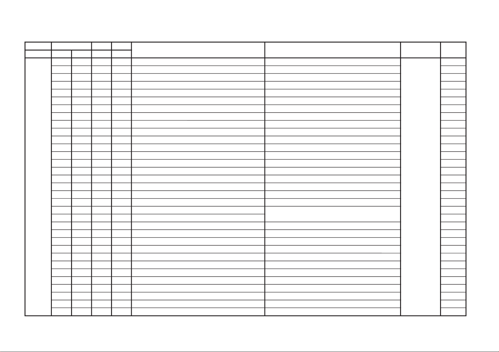
JVTytilanoitcnuF.tinIegnaRnoitcnuFetoN&elbaTemaNeciveDnommoC )deliateD(eulaVlaitinI
yrogetaC.oNemaNceDceD srehtOVUY)VT(LAP)VT(CSTN)VT(MACES)oediV(LAP)oediV(CSTN)oediV(MACESTUPNI-SMACESCSTN
CY000YLDY210510yaleD-Y TUPNI-S/VUY+)OEDIV/VT(*)MACES/CSTN/LAP(
0011606001116001
100TAMC000300xirtaM)ASU/napaJ(CSTNroMACES-LAP 00
200LCA100100gnitimiLroloCcitamotuA 10
300BC000100ycneuqerFretneCssapdnaBamorhC )xif0:oediV*(VThtiwylnodilav00
400OBS100300tesffOkcalBMACES 10
500ESHC100300ytivitisneStnedICSTN/LAP 30
600OLC000100retliF)lleB(ehcolCfoycneuqerFretneC 00
700PRTC000100edoMparTamorhC srehto/MACES
00
10
800SPB000100eniLyaleDdnab-esaBamorhCfossapyB srehto/CSTN
00
10
900OCF000100nOroloCdecroF 00
JVTytilanoitcnuF.tinIegnaRnoitcnuFetoN&elbaTemaNeciveDnommoC)deliateD(eulaVlaitinI
yrogetaC.oNemaNceDceD 0506srehtOVUYVToediVtxeteleTpi-VTlangiSoN
CNYS000SYS000100tupnICNYSYnonoitazinorhcnyS 00
100OF
000300tnatsnoCemiT1esahP
)FR(langisoNrogninuTotuA/txeteleT/oediV/FFOPIVT/NOPIVT
3030100000
200DIV000100edoMtnedIoediV 06/05
0000
300LSF000100cnySlacitreVrofleveLgnicilSdecroF 00
400LSS000100rotarapeScnySleveLgnicilS 06/05
0000
500DIVS100700noitacifitnedIoediVrofnoitceleSecruoS srehtO/VUY
0000
600FROF200300ycneuqerFdleiFdecroF 20
700KVM000100gniyeKnoisiVorcaM 10
JVTytilanoitcnuF.tinIegnaRnoitcnuFetoN&elbaTemaNeciveDnommoC )deliateD(eulaVlaitinI
yrogetaC.oNemaNceDceD
srehtOBGReviLVT
)nyD(
VT
)srehtO(
oediV
)nyD(
oediV
)srehtO(
pmeTroloC
)HGIH(
pmeTroloC
)srehtO(
roloC
)WOL(pmeT
pmeTroloC
)LAMRON(
TCIP100AFC000300edoMretliFbmoC 00
KV-DA34M61/M81
RM-W105
KV-DA34M61/M81
JVTytilanoitcnuF.tinIegnaRnoitcnuFetoN&elbaTemaNeciveDnommoC)deliateD(eulaVlaitinI
yrogetaC.oNemaNceDceD VUYVToediV
WS0002VC000100noitceleSlangiStupnI2SBVC 00
100OVS10030084@niPISBVC/OVS/OVFIfonoitcnuFVUY/oediV/VT
201010
200LFD000100noitcetorPhsalF 10
300FTNI000100langisecafretniVUYfoytiraloP/edutilpmA 00
JVTytilanoitcnuF.tinIegnaRnoitcnuFetoN&elbaTemaNeciveDnommoC
yrogetaC.oNemaNceDceD
FIV000DFIO630360rotaludomeDFItesffO rossecorP-VT63
100TCGA130360revo-ekaTCGA 72
200MTS000100edoMgninuThcraeS 10
300DG000100langiS1SBVCnoyaleDpuorG 00
400SCGA100300deepSCGAFI 10
500IFF000100LLPFIretliFtsaF 00
600IANL100100eulavlaitinitibANLpmAFR 00
700TANL591552leveLdlohserhTpmAFR 591
800NSNL400700dlohserhTleveLNSpmAFR 40
900DSNL200700dlohserhTporDleveLNSpmAFR 10
010XENL610360gnimiTporDNSkcehcpmAFR 03
110RTHC840721edoMresUpmAFRtesotgrPotuAretfadlohserhTlennahC 52
RM-W105
– 20 –
– 21 –
JVTytilanoitcnuF.tinIegnaRnoitcnuFetoN&elbaTemaNeciveDnommoC)deliateD(eulaVlaitinI
yrogetaC.oNemaNceDceD 0edomciP1edomciP2edomciP3edomciP
MV000PAMV200300)FFO:3,2,woL:1,hgiH:0(gnittesMVedoMerutciP
00000000
JVTytilanoitcnuF.tinIegnaRnoitcnuFetoN&elbaTemaNeciveDnommoC
yrogetaC.oNemaNceDceD
MEDS000SWMF000300rotaludomeDMFrofnoitceleSwodniW rossecorP-VT20
100SSQ100100 )metsysMitlumAGrofA/N(edoMreifilpmA)SSQ(dnuoStilpSisauQ *
200BPB000100retliFssapdnaBdnuoSfossapyB 00
300OLMA000100dnuoSMAroflangiStuptuOoiduA 00
400CVPH000100lortnoCemuloVenohPdaeH 00
JVTytilanoitcnuF.tinIegnaRnoitcnuFetoN&elbaTemaNeciveDnommoC
yrogetaC.oNemaNceDceD
TXT000VXT930360spilihProfnoitisoPlacitreVtxeteleT redoceDtxeT93
100DHT010721tfihSegdEevitcAcnys-HtxeteleT 11
200RBT820130)edomllufrof(ssenthgirBBGRtxeteleT 82
300MRBT310130)edomXIMrof(ssenthgirBBGRtxeteleT 31
400BCL000100)XETSAFrofgnittes(elbane:1elbasid:0BCLtxeteleT 00
500DTSN000100)elbasid:1,elbane:0(langiSdradnatSnoNfoM/C 00
KV-DA34M61/M81
(only for model with teletext function)
RM-W105
JVTytilanoitcnuF.tinIegnaRnoitcnuFetoN&elbaTemaNeciveDnommoC )deliateD(eulaVlaitinI
yrogetaC.oNemaNceDceD )oruE(L-VTVToediVffOWOW/SRSdnuorrusurToeretsIonomI
PSDS000MVA200700edoMLVA DSS20
100VVA500510leveLecnerefeRLVA 90
200LBB000510ruotnoCEBB 20
300HBB000510ssecorPEBB
60
400WLBB000510tesffOruotnoCEBB
60
500FOVS000510tesffOemuloVedoMtceffE/dnuorruS onomI/oeretsI/dnuorrusurT/)WOW/SRS(ffO
4011406040
600FOVI000700tesffOevitisoPemuloVretsaM 60
700FOVE000700tesffOevitageNemuloVretsaM 60
800DAL000130tsujdAleveLredoceD 40
900MAL000130tsujdAleveLonoM 40
010NAL000130tsujdAleveLmaciN 22
110SAL000130tsujdAleveLPAS 80
210AAL000130tsujdAleveLCDA oediV/Lnon-VT/L-VTI)oruEnoN(oediV/vT
717100
310FES300700tceffEoeretS/onoMelbidercnI onomI/oeretsI
5030
410L1A000552tfeLemuloV1XUA 00
510R1A000552thgiRemuloV1XUA 00
610SAB000510tesffOssaBniaM 02
710ERT000510tesffOelberTniaM 22
8101QE000510tesffO)zH001(dnaBlennahCniaMrezilauqE 20
9102QE000510tesffO)zH003(dnaBlennahCniaMrezilauqE 22
0203QE000510tesffO)zH0001(dnaBlennahCniaMrezilauqE 00
1204QE000510tesffO)zH0003(dnaBlennahCniaMrezilauqE 81
2205QE000510tesffO)zH0008(dnaBlennahCniaMrezilauqE 10
320TCFB500700lortnoCEBBdnaBUD,EBD 50
420NECS100510lortnoCretneCD3SRS 40
520APSS000510lortnoCecapSD3SRS 10
620WHBB000510edomWOWnitesffossecorpEBB 00
720ERTS200700edomdnuorrusroftesffOelberT 10
820THBB000510edomVTnitesffOEBB 00
920AWD000000???AWD 00
030ERTT200700edoMVTnitesffOelberT 30
1301QEC800510)zH001(ataDdnaBrezilauqEnI-retneC 60
2302QEC800510)zH003(ataDdnaBrezilauqEnI-retneC 90
3303QEC800510)zH0001(ataDdnaBrezilauqEnI-retneC 01
4304QEC800510)zH0003(ataDdnaBrezilauqEnI-retneC 01
5305QEC800510)zH0008(ataDdnaBrezilauqEnI-retneC 70
– 22 –
KV-DA34M61/M81
RM-W105
JVTytilanoitcnuF.tinIegnaRnoitcnuF etoN&elbaTemaNeciveDnommoC
yrogetaC.oNemaNceDceD
CEDS000UTPM300510)CSTB(noitcetedtolipXPMrofdlohserhTreppU DSS20
100LTPM900510)CSTB(noitcetedtolipXPMrofdlohserhTrewoL 50
200UTPS300510noitcetedreirracPASrofdlohserhTreppU 80
300LTPS600510noitcetedreirracPASrofdlohserhTrewoL 51
400HT1C0001301CSfonoitcetedrofdlohserhTlamroN 00
500PA1C0001301CSfonoitcetedrofdlohserhTmargorPotuA 00
600HTPS000130PASfoetumotuarofdlohserhTesioN 00
700YHPS400510PASfoetumotuarofezissiseretsyH 30
800HTMF000130dradnats2AMFni2CSfoetumotuarofdlohserhTesioN 81
900YHMF400510dradnats2AMFni2CSfoetumotuarofezissiseretsyH 70
010HTTB000130reirracoeretsCSTBfoetumotuarofdlohserhTesioN 00
110YHTB400510oeretsCSTBfoetumotuarofezissiseretsyH 30
210HTJE000130reirracbusMFJAIEfoetumotuarofdlohserhTesioN 00
310YHJE400510reirracbusMFJAIEfoetumotuarofezissiseretsyH 40
410YLNO000100tuptuoCEDnoMACINdetalerylnoecudorpeR 00
510MAXE000100)PEDD(LdradnatsnietumotuafoesacniecruoskcabllaF 00
610TMIN000100)PEDD(etarrorretibnodnepednoitcnufetumotuaMACIN 00
710ELIN001552)PEDD(timilrorrerewolMACIN 05
810EUIN002552)PEDD(timilrorrereppuMACIN 002
910DMPE100300)PEDD(gnimmargorPysaECEDMED
1=1tiB3POdna0=SDTSdna0=DMPEfI
revoekatlliwyrogetacCKDSdnaelbasiDsiyrogetacCEDS
*
020SDTS910130sedomSSSdnaDSArofdexelpitlumstiB *
120AMVO100100noitpadanoitaludomrevoMF 00
220WBLF000300htdiwdnabretlifrotaludomedMA/MF 30
320DMDI000300edomSSSnideepstnediMF 00
420LAPF000100gnidocedCSTBrofycneuqefeniL 00
520TMVO100200lanimonotevitalerdlohserhtlevelnoitaludomrevO 30
620IXCD000100retrevnIlortnoCgnilacSOXCDMACIN *
720GXCD000700niaGlortnoCgnilacSOXCDMACIN *
820LLCD110510)L(timiLlortnoCgnilacSOXCDMACIN 00
920HLCD000130)H(timiLlortnoCgnilacSOXCDMACIN *
030UEDI100300DTS2AnaeporuErofgnittesDOMDI 00
130RKDI100300DTSMnaeroKrofgnittesDOMDI 00
230PJDI100300DTSJAIErofgnittesDOMDI 00
– 23 –
KV-DA34M61/M81
RM-W105
JVTytilanoitcnuF.tinIegnaRnoitcnuF etoN&elbaTemaNeciveDnommoC
yrogetaC.oNemaNceDceD
CKDS000LLNK000552etyBrewoLdlohserhTrewoLteDesioNnaeroK
1=1tiB3POdna0=SDTSdna0=DMPEfI
revoekatlliwyrogetacCKDSdnaelbasiDsiyrogetacCEDS
100HLNK210552etyBrehgiHdlohserhTrewoLteDesioNnaeroK
200LHNK000552etyBrewoLdlohserhTreppUteDesioNnaeroK
300HHNK020552etyBrehgiHdlohserhTreppUteDesioNnaeroK
400CILK060552tnuocgniniatniamDItoliPtsoLnaeroK
500MILK100721reilpitlumtnuocgniniatniamDItoliPtsoLnaeroK
600CDSK600552tnuoCtceteDoeretSnaeroK
(only applicable fo Korea model)
– 24 –
KV-DA34M61/M81
RM-W105
JVTytilanoitcnuF
.tinIegnaRnoitcnuFetoN&elbaTeciveD
emaN
nommoC )deliateD(eulaVlaitinI
yrogetaC.oNemaNceDceD
0RN1RN2RN3RN0CSTN1CSTN1RN-FR-FR
1CSTN
-VT
LAP
-VT
CSTN
OEDIV
LAP-
-OEDIV
CSTN
-S
LAP
-S
CSTN
RN3
000SCY
000300EDOMSCY bmoCD300
100CER
000100CED-C:CER 10
200TED3000700TEDD3
/1tN/0TN/3RN/2RN/1RN/0RN
1CSTN-FR/1RN-FR
7070707070707070
300ROC3000100RROCRND3
/1tN/0TN/3RN/2RN/1RN/0RN
1CSTN-FR/1RN-FR
1000000010000000
400FOB
000100NOTSRUB 10
500NYS
000100NOCNYS 00
600CFA000300NIAGCFA
/1tN/0TN/3RN/2RN/1RN/0RN
1CSTN-FR/1RN-FR
3030303030303030
700GEH000300NIAGAHNEH 00
800RNC2000510MILRNCD2&KRNC-D2
/1tN/0TN/3RN/2RN/1RN/0RN
1CSTN-FR/1RN-FR
0040509000004000
900CNY000700MILCN-Y;RELLECNACESIONY
/1tN/0TN/3RN/2RN/1RN/0RN
1CSTN-FR/1RN-FR
0030507010104030
010RNY2000510NIAGRNYD2;KRNYD2
/1tN/0TN/3RN/2RN/1RN/0RN
1CSTN-FR/1RN-FR
0000008010102040
110LNY2000300MILRNYD2
/1tN/0TN/3RN/2RN/1RN/0RN
1CSTN-FR/1RN-FR
0020003020203020
210KLB000300PXEKLB 00
310RNC3000700MILRNCD3
/1tN/0TN/3RN/2RN/1RN/0RN
1CSTN-FR/1RN-FR
0000307000000000
410KNC3000300KRNCD3
/1tN/0TN/3RN/2RN/1RN/0RN
1CSTN-FR/1RN-FR
0000000000000000
510GNC3000700NIAGRNCD3
/1tN/0TN/3RN/2RN/1RN/0RN
1CSTN-FR/1RN-FR
0020207000004000
610RNY3000700MILRNYD3
/1tN/0TN/3RN/2RN/1RN/0RN
1CSTN-FR/1RN-FR
0030606000001000
710KNY3000300KRNYD3
/1tN/0TN/3RN/2RN/1RN/0RN
1CSTN-FR/1RN-FR
0010000000001000
810GNY3000700NIAGRNYD3
/1tN/0TN/3RN/2RN/1RN/0RN
1CSTN-FR/1RN-FR
0020606000001000
910YLDY000821YALEDTUPTUOY
/LAP-DIV/CSTN-VT/LAP-VT
CSTN-S/LAP-S/CSTN-DIV
307060505151
020ACI000100OTUAPMALCTNI 00
120MCI000100LAUNAMPMALCTNI 00
220HNEC000100AHNEC 10
320KCI000100YEKPMALCTUPNI 10
420KGB000100YEKETAGTSRUB 10
520LSS000100FPLPESCNYS 00
– 25 –
KV-DA34M61/M81
RM-W105
KV-DA34M61/M81
JVTytilanoitcnuF
.tinIegnaRnoitcnuFetoN&elbaTeciveD
emaN
nommoC )deliateD(eulaVlaitinI
yrogetaC.oNemaNceDceD
0RN1RN2RN3RN0CSTN1CSTN1RN-FR-FR
1CSTN
-VT
LAP
-VT
CSTN
OEDIV
LAP-
-OEDIV
CSTN
-S
LAP
-S
CSTN
lamroN
)3:4(
DHxednI/niwT
paP/
rehtO
RN3
620RCEV000300EROCAHNEV
/1tN/0TN/3RN/2RN/1RN/0RN
1CSTN-FR/1RN-FR
bmoCD3
0010300000101010
720GEV000300NIAGAHNEV
/1tN/0TN/3RN/2RN/1RN/0RN
1CSTN-FR/1RN-FR
0000100000102010
820NEV000300LNAHNEV
/1tN/0TN/3RN/2RN/1RN/0RN
1CSTN-FR/1RN-FR
0000100000102010
9201PMA0007001PMADH
/1tN/0TN/3RN/2RN/1RN/0RN
1CSTN-FR/1RN-FR
6060606060606060
030VGDH000130VNIAGDH
/1tN/0TN/3RN/2RN/1RN/0RN
1CSTN-FR/1RN-FR
8181818181818181
1302PMA0007002PMADH
/1tN/0TN/3RN/2RN/1RN/0RN
1CSTN-FR/1RN-FR
6060606060606060
2301GDH0001301NIAGDH
/1tN/0TN/3RN/2RN/1RN/0RN
1CSTN-FR/1RN-FR
3131313131313131
3303PMA0007003PMADH
/1tN/0TN/3RN/2RN/1RN/0RN
1CSTN-FR/1RN-FR
5050505010105010
4302GDH0001302NIAGDH
/1tN/0TN/3RN/2RN/1RN/0RN
1CSTN-FR/1RN-FR
4040404010104010
530PLSC000510PLSSCA&PLSMCA
/1tN/0TN/3RN/2RN/1RN/0RN
1CSTN-FR/1RN-FR
5141015101010101
630PLSY000510PLSSYA&PLSMYA
/1tN/0TN/3RN/2RN/1RN/0RN
1CSTN-FR/1RN-FR
5151400141414141
730SMCA000510TESFMCA&TESEMCA
/1tN/0TN/3RN/2RN/1RN/0RN
1CSTN-FR/1RN-FR
5101015151510151
830SSCA000510TESFSCA&TESESCA
/1tN/0TN/3RN/2RN/1RN/0RN
1CSTN-FR/1RN-FR
5101015101010101
930SMYA000510TESFMYA&TESEMYA
/1tN/0TN/3RN/2RN/1RN/0RN
1CSTN-FR/1RN-FR
5111015151511151
040SSYA000510TESFSYA&TESESYA
/1tN/0TN/3RN/2RN/1RN/0RN
1CSTN-FR/1RN-FR
5111015101014101
140LSCB000510PLSSCB&PLSMCB
/1tN/0TN/3RN/2RN/1RN/0RN
1CSTN-FR/1RN-FR
51
01015151510151
240LSYB000510PLSSYBPLSMYB
/1tN/0TN/3RN/2RN/1RN/0RN
1CSTN-FR/1RN-FR
5101015131310131
340SMCB000510TESFMCB&TESEMCB
/1tN/0TN/3RN/2RN/1RN/0RN
1CSTN-FR/1RN-FR
5101015101010101
440SSCB000510TESFSCB&TESESCB
/1tN/0TN/3RN/2RN/1RN/0RN
1CSTN-FR/1RN-FR
5101015101010101
540SMYB000510TESFMYBTESEMYB
/1tN/0TN/3RN/2RN/1RN/0RN
1CSTN-FR/1RN-FR
5151015151515151
640SSYB000510TESFSYBTESESYB
/1tN/0TN/3RN/2RN/1RN/0RN
1CSTN-FR/1RN-FR
5151015101015101
740UMCB000100PUMCB
10
840MCEC000700PMCEC
/1tN/0TN/3RN/2RN/1RN/0RN
1CSTN-FR/1RN-FR
7040704040407040
940MCSC000510PMCSC
/1tN/0TN/3RN/2RN/1RN/0RN
1CSTN-FR/1RN-FR
5101510000005100
050VH1F000510REV1F&REH1F
/1tN/0TN/3RN/2RN/1RN/0RN
1CSTN-FR/1RN-FR
5080505050508050
150FERM000510FERM
/1tN/0TN/3RN/2RN/1RN/0RN
1CSTN-FR/1RN-FR
2070404060607060
250YEDC000300EYEDC
/1tN/0TN/3RN/2RN/1RN/0RN
1CSTN-FR/1RN-FR
2030202000003020
350YEDY000300EYEDY
/1tN/0TN/3RN/2RN/1RN/0RN
1CSTN-FR/1RN-FR
2030202000003020
450SAMH000700TUOKSAM-H
00
550SAMV000130TUOKSAM-V
00
RM-W105
– 26 –
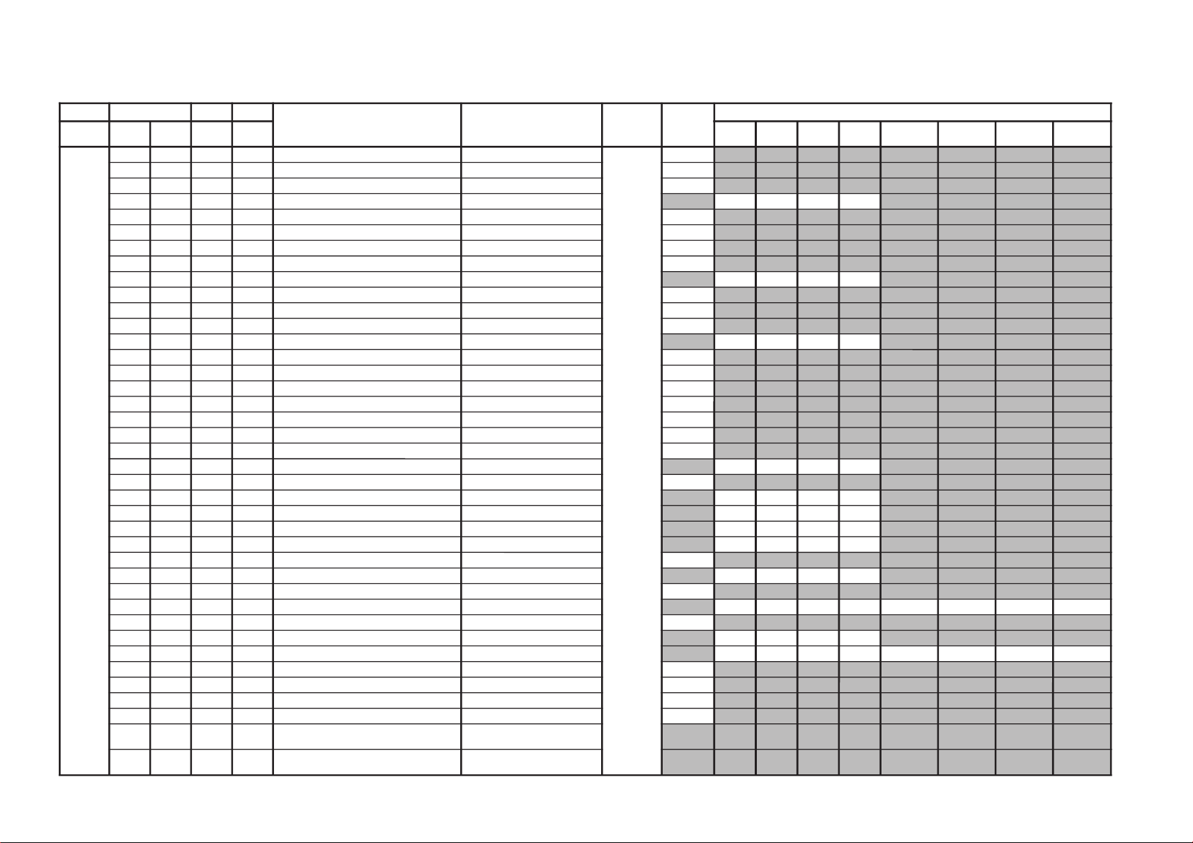
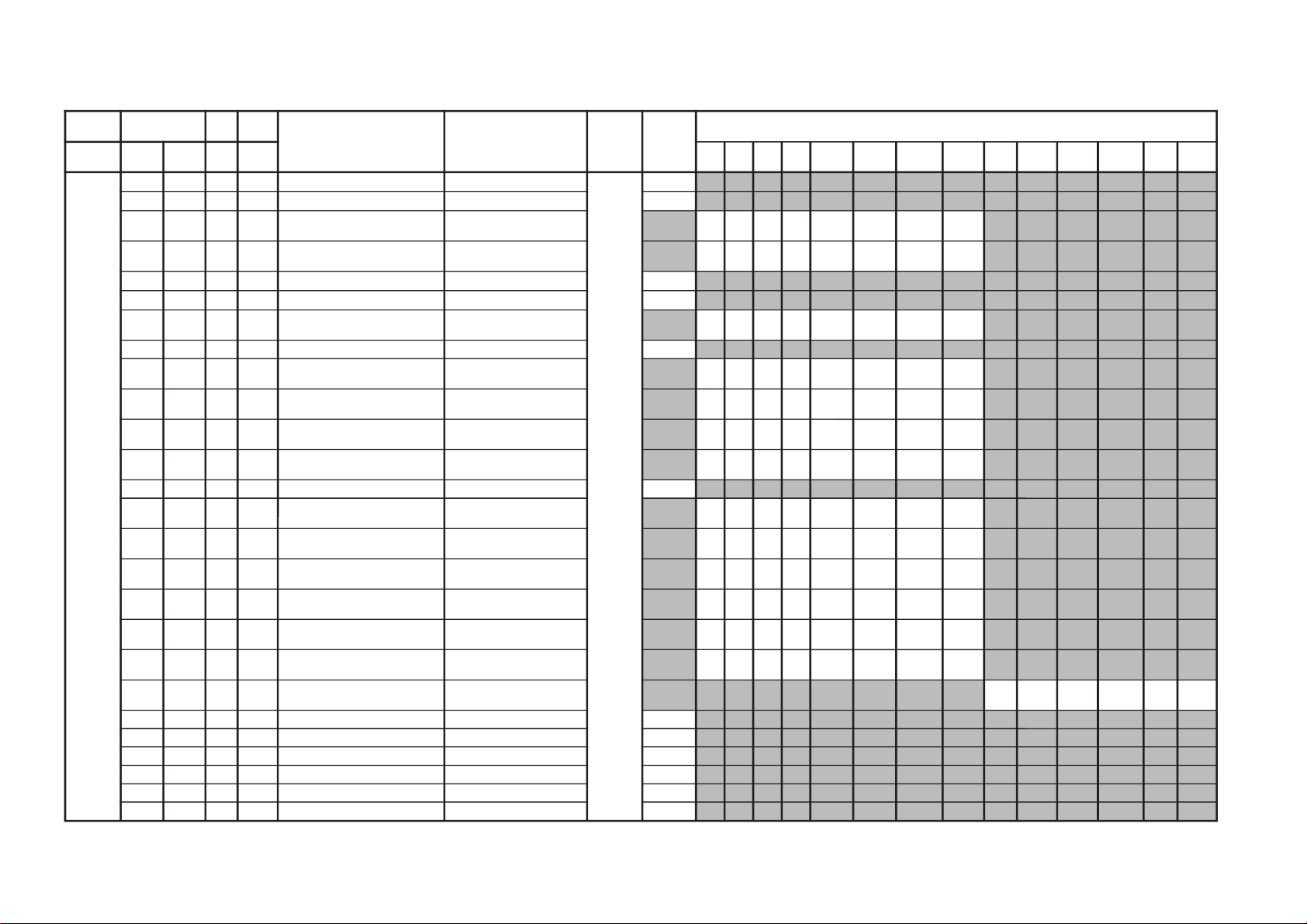
GVTytilanoitcnuF
laitinIegnaRnoitcnuFetoN&elbaTeciveD
emaN
nommoC
)deliateD(eulaVlaitinI
yrogetaCoNemaNceDceD
ciP
0edom
ciP
1edom
ciP
2edom
ciP
3edom
FRtpecxE
0edomciP
FRtpecxE
1edomciP
FRtpecxE
2edomciP
FRtpecxE
3edomciP
ITL000HDL100100noitceleStnemgesmargotsiH 8719ADT10
100SFC100100noitceleSretliFruotnoC 10
200BLW000100hctiwSwodniWxobretteL 00
300CDV100100gniroCtnednepeDoediVedoMerutciP
10101010
400MED000100edoMnoitartsnomeD 00
500PDC400700yaleDecnanimuL 40
600PSO000100gnikaePtramSelurrevO 00
700OPW000100ffOhctertStnioPetihW 00
800KSD000100hctiwSenoTnikSedoMerutciP
00000000
900KSA000100noitceleSelgnAenoTnikS 00
010KSW000100noitceleShtdiWenoTnikS 00
110KSS000100noitceleSeziSenoTnikS 00
210RGD100100hctiwStnemecnahnEneerGedoMerutciP
10100010
310TGD700700hctiwStnemecnahnEneerGfodlohserhT 70
410RGG000100niaGtnemecnahnEneerG 00
510RGW000100htdiWtnemecnahnEneerG 00
610RGS000100eziStnemecnahnEneerG 00
710LBD000100hctiwShctertSeulB 00
810LBG000100noitceleSniaGhctertSeulB 00
910LBS000100noitceleSeziShctertSeulB 00
020SDC100100ssenprahStnednepeDroloCedoMerutciP
10100010
120TSC700700ssenprahStnednepeDroloCfodlohserhT 70
220ITC100100tnemevorpmItneisnarTroloCedoMerutciP
10100010
320NOB000100noitasnepmoCtesffOkcalBedoMerutciP
00000000
420DTB000360htcertSkcalBevitpadAedoMerutciP
00000000
520DLN120360reifilpmAytiraeniL-noNedoMerutciP
12120012
620WLN700700reifilpmAytiraeniL-noNfohtdiWpetS 70
720DGV130360ammaGelbairaVedoMerutciP
53535353
820WGV000700ammaGelbairaVfohtdiWpetS 00
920DKP040360edutilpmAgnikaeP)srehtO/VT(*edoMerutciP
0403410404034104
030WKP800510edutilpmAgnikaePfohtdiWpetS 80
130DPS000360noitcerroCssenpeetSedoMerutciP
00000000
230DRC050360leveLgniroC)srehtO/VT(*edoMerutciP
5454005405050005
330WRC900510leveLgniroCfohtdiWpetS 60
430ORC600510edoMoediVroftesffOleveLgniroC 60
530DWL130360noitcerroChtdiWeniL 13
630MNS000700noitidnocN/SelbailernurednuedoMN/S 00
730CNS300510retnuoCegarevAoitaRN/S
noelbaliavAtoNmetIecivreS
)E3GAmorfdeipoC(VTlautca
830CMF200510retnuoCgnihctaMedoMerutaeF
noelbaliavAtoNmetIecivreS
)E3GAmorfdeipoC(VTlautca
– 27 –
KV-DA34M61/M81
RM-W105
– 28 –
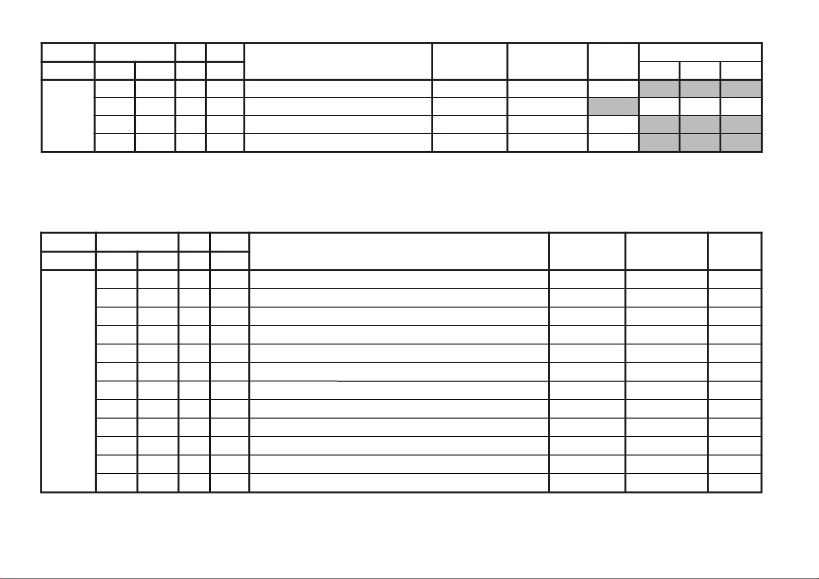
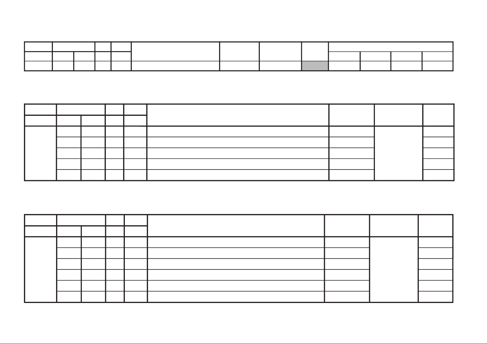
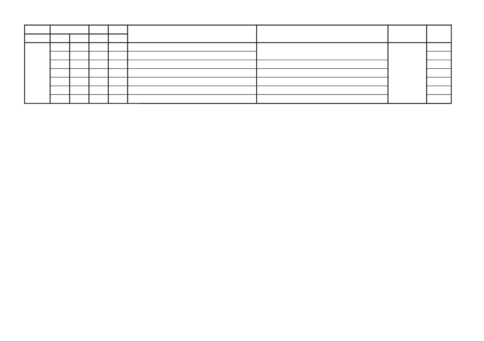
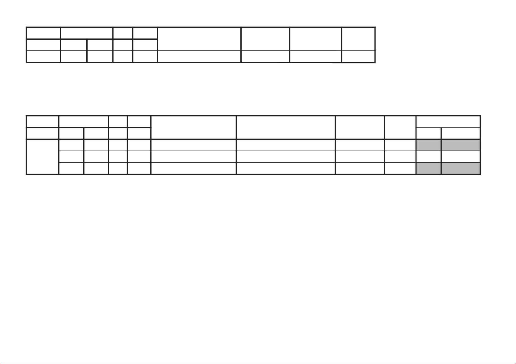
JVTytilanoitcnuF.tinIegnaRnoitcnuFetoN&elbaTemaNeciveDnommoC
yrogetaC.oNemaNceDceD
DEFP000DEFP000100edoMecivreSenignEFPenignEFP00
JVTytilanoitcnuF.tinIegnaRnoitcnuFetoN&elbaTemaNeciveDnommoC)deliateD(eulaVlaitinI
yrogetaC.oNemaNceDceD 0506
PBUS000HXDI500510noitisoplatnozirohDSOxednIataDtimsnarTossaciPbuSossaciPbuS50
100VXDI740360noitisoplacitrevDSOxednI)06/05(ataDtimsnarTossaciPbuSossaciPbuS7474
200BXDI130130ssenthgirbDSOxcednIataDtimsnarTossaciPbuSossaciPbuS13
(only applicable for 2 tuners models)
KV-DA34M61/M81
RM-W105

JVTytilanoitcnuF.tinIegnaRnoitcnuFetoN&elbaTemaNeciveDnommoC)deliateD(eulaVlaitinI
yrogetaC.oNemaNceDceD 0506VUYVToediVlangiSoN
SOCS000SYS100100tupnICNYSYnonoitazinorcnyS -VTbuS
rossecorP
00
100OF000300tnatsnoCemiT1esahP )FR(langisoNrogninuTotuA/VT
003000
200DIV100100edoMtnedIoediV 06/05
0000
300LSF000100cnySlacitreVrofleveLgnicilSdecroF 00
400LSS000100rotarapeScnySleveLgnicilS 06/05
0000
500DIVS000700noitacifitnedIoediVrofnoitceleSecruoS VUY/oediV/VT
000000
600FROF300300ycneuqerFdleiFdecroF 20
700OVS00030084@niPISBVC/OVS/OVFIfonoitcnuF VUY/oediV/VT
000000
800EXDV
000100dnareifilpmaFInoisivneewtebgnilpuocfolortnoC
tiucricnoitasinorhcnys
00
900XDV
000100dnareifilpmaFInoisivneewtebgnilpuoC
tiucricnoitasinorhcnys
00
010YLDY210510tnemtsujdayaled-Y 21
110DFIO630360rotaludomeDFItesffO 63
210TCGA130360revo-ekaTCGA 13
310MTS100100edoMgninuThcraeS 10
410DG000100langiS1SBVCnoyaleDpuorG 00
510SCGA100300deepSCGAFI 10
610IFF000100LLPFIretliFtsaF 00
710SSMC000100tiucrictnedioedivehtroflangistupnicnysfonoitceleS 00
810PMAO300300edutilpmAlangiStuptuOoediV 00
910IAV000100noitcerroCedutilpmAlangiStuptuOImetsyS 00
020SWMF200300rotaludomeDMFrofnoitceleSwodniW 20
120SSQ
000100edoMreifilpmA)SSQ(dnuoStilpSisauQ
)ledoMAGtpecxe(
00
220BPB000100retliFssapdnaBdnuoSfossapyB 00
3202BPB0001002retliFssapdnaBdnuoSfossapyB 00
420TPS000100edomkcirtecnamrofrepcnyS 00
520D2E000100nipMEEDUAnolangistuptuooiduafonoitceleS 00
620CVPH000100lortnoCemuloVenohPdaeH 00
720GSD000100stuptuooiduaotstupnioiduamorfniaG 00
820DSV100100elbasidnacslacitreV 00
920ESHC100300ytivitisneStnedICSTN/LAP 20
– 29 –
(only applicable for 2 tuners models)
KV-DA34M61/M81
RM-W105
 Loading...