

Page 1

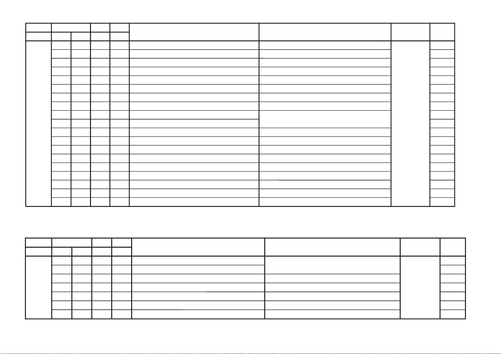
REVISION HISTORY
CX1
CHASSIS
MODEL
KV-DA322M64
KV-DA322M66
NO. SUFFIX DATE SUPP / CORR DESCRIPTION
1 -01 2005/9 _ _ 1st Issue
PA RT NO.: 9-872-850-02
2 -02 2005/12 CORR-1 Correction on Deflection Adjustment (Page 157)
Page 2

SERVICE MANUAL
CX1
CHASSIS
MODEL COMMANDER DEST. CHASSIS NO.
KV-DA322M64 RM-GA001 Thailand SCC-V27D-A
KV-DA322M66 RM-GA001 GE SCC-V25D-A
MODEL COMMANDER DEST. CHASSIS NO.
RM-GA001
TRINITRON
®
COLOR TV
Page 3

KV-DA322M64/M66
RM-GA001
TABLE OF CONTENTS
Section Title Page
SELF DIAGNOSTIC FUNCTION................................... 3
1. DISASSEMBLY
1-1. Rear Cover Removal.................................................. 5
1-2. Speaker Removal........................................................5
1-3. Chassis Assy Removal................................................5
1-4. Service Position..........................................................5
1-5. Terminal Bracket Removal......................................... 5
1-6. J1 Board Removal.......................................................5
1-7. BH1, BP1 and BC1 Boards Removal..........................6
1-8. F1 Board Removal......................................................6
1-9. WL Board Removal....................................................6
1-10. DL Board Removal.....................................................6
1-11. H2 and H3 Boards Removal....................................... 6
1-12. A and D Boards Removal...........................................6
1-13. Picture Tube Removal................................................ 7
2. SERVICE JIG
2-1. Jigs Required for Servicing........................................ 8
3. CIRCUIT BOARDS LOCATION ........................................ 8
4. ADVANCE OPERATION
4-1. "RESET" Function.................................................... 9
Section Title Page
7. DIAGRAMS
7-1. Block Diagram......................................................... 65
7-2. Schematic Diagram Information...............................66
7-2-1. A Board – (Block 001)...................................67
7-2-2. A Board – (Block 002)...................................69
7-2-3. A Board – (Block 003)...................................71
7-2-4. A Board – (Block 004)...................................73
7-2-5. BC1 Board Schematic Diagram.....................74
7-2-6. BH1 Board – (Block 001).............................. 76
7-2-7. BH1 Board – (Block 002)............................. 78
7-2-8. BP1 Board Schematic Diagram..................... 80
7-2-9. C Board Schematic Diagram........................ 82
7-2-10. D Board – (Block 001)................................ 84
7-2-11. D Board – (Block 002)................................ 86
7-2-12. DL Board Schematic Diagram .................... 87
7-2-13. H2 Board Schematic Diagram .....................89
7-2-14. F1 Board Schematic Diagram ..................... 90
7-2-15. H3 Board Schematic Diagram..................... 91
7-2-16. VM1 Board Schematic Diagram.................. 93
7-2-17. J1 Board Schematic Diagram.......................95
7-2-18. WL Board Schematic Diagram.................. 97
7-3. Voltage Measurement and Waveform..................... 98
7-4. Printed Wiring Boards............................................ 110
7-5. Semiconductors...................................................... 122
5. SET-UP ADJUSTMENTS
5-1. Beam Landing Adjustment....................................... 10
5-2. Convergence Adjustment.......................................... 11
5-3. Focus Adjustment..................................................... 13
5-4. G2 (SCREEN) Adjustments......................................13
5-5. Sub Brightness Adjustment.......................................13
5-6. White Balance Adjustment........................................13
6. CIRCUIT ADJUSTMENTS
6-1. Adjustments With Commander..................................15
6-2. Adjustment Method.................................................. 16
6-3. Picture Quality Adjustments.....................................61
6-4. Sub Hue/Col Adjustment.........................................61
6-5. Deflection Adjustments............................................ 62
6-6. A1 Board Adjustment After IC003
(Memory) Replacement............................................63
6-7. Picture Distortion Adjustments.................................64
8. EXPLODED VIEWS
8-1. Picture Tube and Speaker Bracket.......................... 124
8-2. Chassis....................................................................125
9. ELECTRICAL PARTS LIST ........................................... 126
OPERATING INSTRUCTIONS
CAUTION
SHORT CIRCUIT THE ANODE OF THE PICTURE TUBE AND THE
ANODE CAP TO THE METAL CHASSIS, CRT SHIELD, OR
CARBON PAINTED ON THE CRT, AFTER REMOVING THE
ANODE.
SAFETY-RELATED COMPONENT WARNING!!
COMPONENTS IDENTIFIED BY SHADING AND MARK ! ON THE
SCHEMATIC DIAGRAMS, EXPLODED VIEWS AND IN THE
PARTS LIST ARE CRITICAL TO SAFE OPERATION. REPLACE
THESE COMPONENTS WITH SONY PARTS WHOSE PART
NUMBERS APPEAR AS SHOWN IN THIS MANUAL OR IN
SUPPLEMENTS PUBLISHED BY SONY.
– 2 –
Page 4

KV-DA322M64/M66
SELF DIAGNOSTIC FUNCTION
The units in this manual contain a self-diagnostic function. If an error occurs, the STANDBY/TIMER lamp will automatically
begin to flash.
The number of times the lamp flashes translates to a probable source of the problem. If an error symptom cannot be
reproduced, the remote commander can be used to review the failure occurrence data stored in memory to reveal past
problems and how often these problems occur.
1. DIAGNOSTIC TEST INDICATORS
When an error occurs, the STANDBY/TIMER lamp will flash a number of times to indicate the possible cause of the
problem. If there is more than one error, the lamp will identify the first of the problem areas.
Result for all of the following diagnostic items are displayed on screen. No error has occured if the screen displays a “0”.
RM-GA001
Diagnostic
Item
Description
•Power does not
turn on
• +B overcurrent
(OCP)
• Horizontal
deflection failure
• +B overvoltage
(OVP)
•Vertical deflection
failure
• White balance
failure (no
PICTURE)
• 5V/9V failure
• Micro reset
No. of times
STANDBY/TIMER
lamp flashes
Does not light
2 times
3 times
4 times
5 times
8 times
—
Self-diagnostic
display/Diagnostic
result
—
002:000 or
002:001~255
003:000 or
003:001~255
004:000 or
004:001~255
005:000 or
005:001~255
008:000 or
008:001~225
101:00 or
101:001~225
Probable
Cause
Location
•Power cord is not plugged
in.
• Fuse is burned out F1601
(F1 Board)
• H.OUT Q6802 is shorted.
• PH6602 faulty.
D6644 faulty
• 11V is not supplied.
(D board)
•V.OUT IC6801 faulty
D6827 faulty
D6817 faulty
• G2 is improperly adjusted.
•CRT problem.
• Video OUT IC9001, 9002,
9003 are faulty. (C board)
• IC4301 CXA2170Q (A
board) are faulty.
• 5V regulator (IC2601) faulty.
• 9V regulator (IC2600) faulty.
•CRT Discharge (C Board)
• Static discharge
• External noise
Detected
Symptoms
•Power does not turn on.
• No power is supplied to the
TV.
•AC power supply is faulty.
•Power does not turn on.
• Load on power line is
shorted.
•H pulse output is too high.
•Power does not come on.
•Vertical deflection pulse is
stopped.
•Vertical size is too small.
•Vertical deflection stopped.
• No raster is generated.
•CRT cathode current
detection reference pulse
output is small.
• TV Blank
• No Raster
•Power is shut down shortly,
after this return back to
normal.
• Detect Micro latch up.
2. STANDBY INDICATOR BLINKING PROCESS
Lamp ON 300ms
Lamp OFF 300ms
The example above represents for 4 times blink
Lamp OFF 3 seconds
3. STANDBY INDICATOR ON TV FRONT PANEL
Standby indicator
– 3 –
Page 5
KV-DA322M64/M66
RM-GA001
4. SELF DIAGNOSTIC SCREEN DISPLAY
SELF DIAGNOSTIC
2 : 000
3 : N/A
4 : 000
5 : 001
8 : 002
101 : N/A
5. HANDLING SELF DIAGNOSTIC SCREEN DISPLAY
No. Description Method
1. Display self diagnostic screen [Display] t [Channel ] t [Volume ] t [Power / TV]
2. Stop standby flash i) Turn off power switch on main.
3. Clear fault result In self diagnostic screen, press [Channel ] t -
4. Quit self diagnostic screen Turn off power switch of remote commander or main unit.
"0" means no fault has been detected.
"1" means a fault has been detected.
"2" means two faults has been detected.
"N/A" means not available for this models.
5
Note: The above must be performed while TV is on standby mode.
ii) Unplug power cord from the outlet.
8
Note: Diagnostic results display on screen is not automatically cleared. Therefore,
clear result after completion of repair.
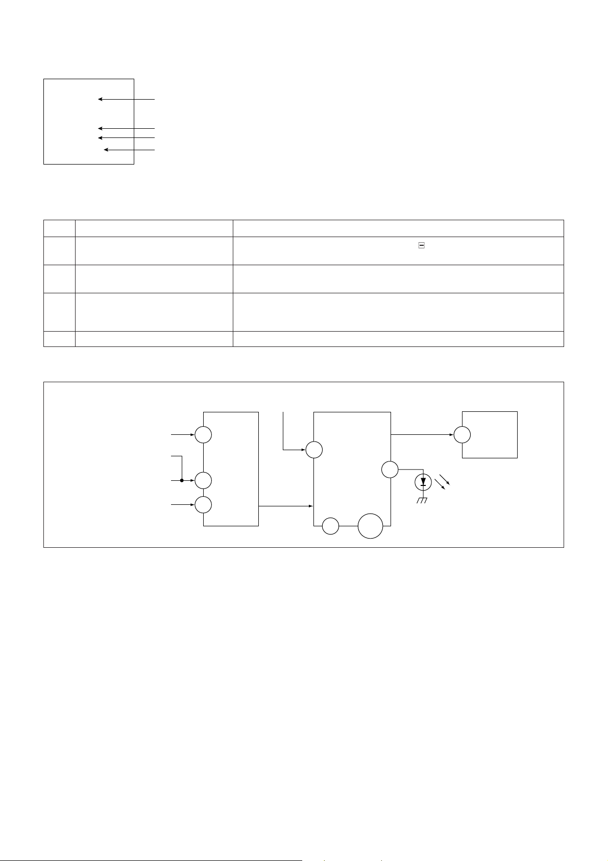
6. SELF-DIAGNOSTIC CIRCUIT
FROM
CRT (IK)
[OCP] Q6804, D6821
[H] D6808, D6809
[V] Q6808
IC4301
RGB JUNGLE
IK_IN
57
H PROT
56
V PROT
CXA2170AQ
OVP
SDA
SYSTEM
2
9V
IC001
84
RED LED
5V
14,47,
82
IC004
MEMORY
SDA
7
524
[+B overcurrent OCP ] Occurs when an overcurrent on the +B(135) line is detected by Q6804.
[High voltage protector of Horizontal Deflection] If Q6804 go to ON, the voltage to the pin57 of IC4301 go to "HIGH".
The unit will automatically turn off.
Occurs when an overvoltage of horizontal pulse is detected by D6809.
If the voltage of anode D6809, Q6814 and D6808 goes to High, the voltage
to pin57 of IC4301 go to "HIGH".
The unit will automatically turn off.
[+B overvoltage OVP ] Occurs when an overvoltage on the +B(135) line is detected by D6635 and
Q6606. If Q6606 go to ON, the voltage to pin2 of IC001 go to "HIGH". The
unit will automatically turn off.
[Vertical deflection failure] Occurs when an absence of the vertical deflection pulse is detected by
Q6808. Shut down the power supply.
[White balance failure] If the RGB levels do not balance or become low level within 5 seconds. This
error will be detected by IC4301.
TV will stay on, but there will be no picture.
[5V/9V failure] Occurs when 5V/9V is not supplied to Micon (IC001).
No raster will be detected or no picture.
– 4 –
Page 6
SECTION 1
DISASSEMBLY
KV-DA322M64/M66
RM-GA001
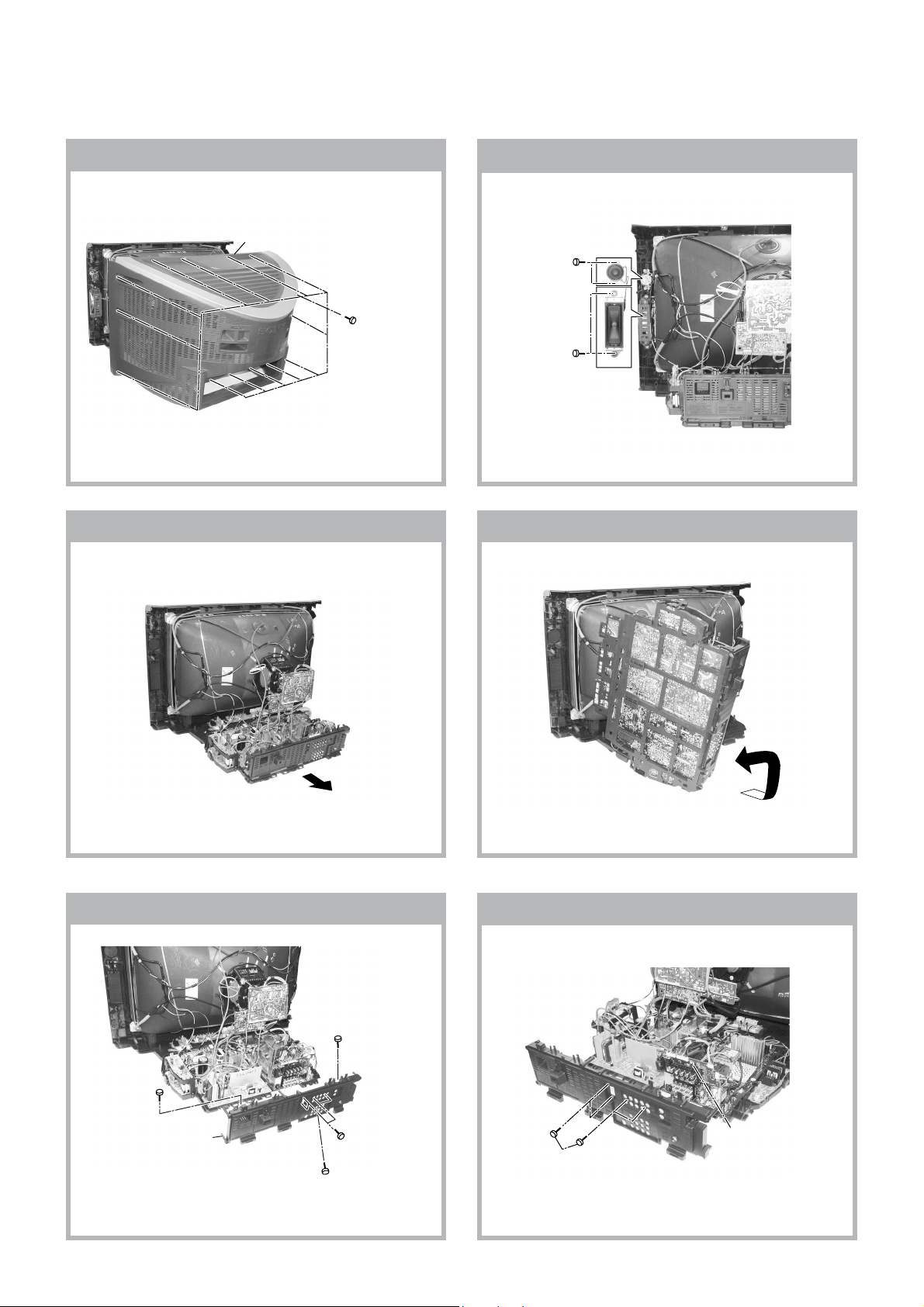
1-1. REAR COVER REMOVAL
2 Rear cover
1 Fourteen screws
(+BVTP 4 × 16
TYPE2 IT-3)
1-2. SPEAKER REMOVAL
1 Two screws
(+BVTP 4 × 16
TYPE2 IT-3)
2 Two screws
TAPPING SCREW
(+PWH 4X16)
1-3. CHASSIS ASSY REMOVAL 1-4. SERVICE POSITION
1-5. TERMINAL BRACKET REMOVAL
5 One screw
(+BVTP 3 × 12)
4 One screw
(+BVTP 3 × 12)
3 Terminal bracket
2 Four screws
(+BVTP 3 × 12
TYPE2 IT-3)
1 One screw
(+BVTP 4 × 16
TYPE2 IT-3)
1-6. J1 BOARD REMOVAL
1 J1 Board
2 Four screws
(+BVTP 3 × 12 TYPE2 IT-3)
– 5 –
Page 7
KV-DA322M64/M66
RM-GA001
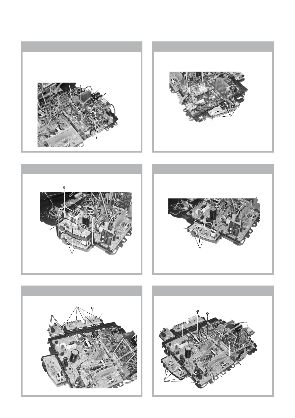
1-7. BH1, BP1 AND BC1 BOARDS REMOVAL
1-8. F1 BOARD REMOVAL
Note: Access to the BH1 board is possible after
removal of the shiledcase. Remove the
shiledcase by removing 2 screws +BVTP 3x12
Type2 IT-3
5 BH1 Board
4 BC Board
6 Two clips
3 Two clips
2 BP1 Board
2 F1 Board
1 Two clips
1-9. WL BOARD REMOVAL 1-10. DL BOARD REMOVAL
2 Three screws
+BVTP 3X12 TYPE2 IT-3
1 Four hooks
2 WL Board
1 Three clip
2 DL Board
1 Three clip
1-11. H2 AND H3 BOARDS REMOVAL 1-12. A AND D BOARDS REMOVAL
5 One screw
(Washer Head)
(3 × 12)(+)(BVTAP)
2 Five screws
(3 × 12)(+) BVTAP
4 H2 Board
3 Four hooks
1 Five hooks
3 One screw
(3X12)(+)BVTAP
2 H3 Board
3 Two hooks
7 D Board
– 6 –
4 A Board
6 Five hooks
Page 8
KV-DA322M64/M66
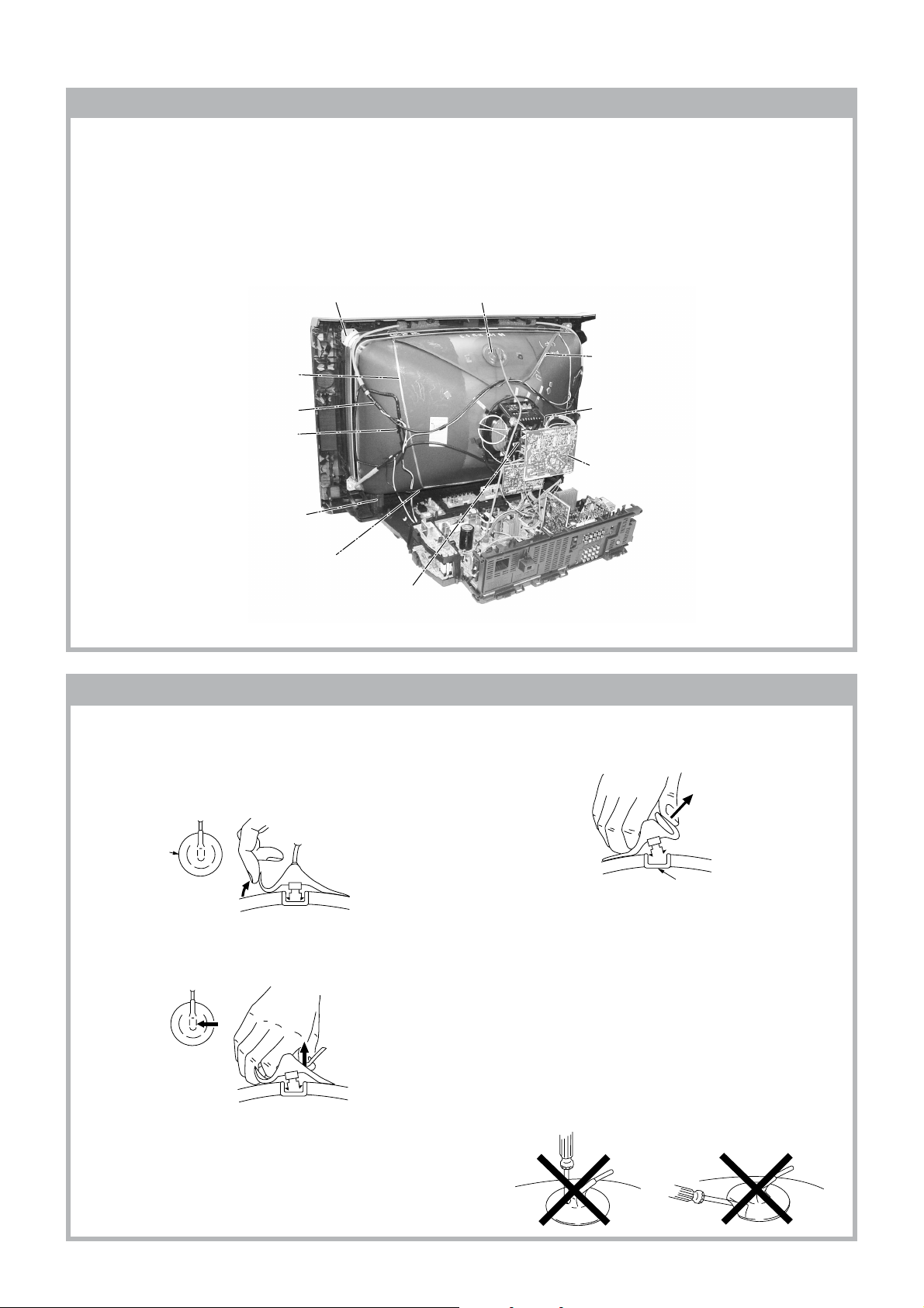
1-13. PICTURE TUBE REMOVAL
Note:
• Please make sure the TV set is not in standing position before removing necessary CRT support located on bottom right
and left.
1) Remove the Rear Cover.
2) Unplug all interconnecting leads from the Deflection yoke, Neck assy, Degaussing Coil and CRT grounding strap. Remove
Chassis Assy.
3) Place the TV set with the CRT face down on a cushion jig.
RM-GA001
qf Screw Tapping 7 +
Crown Washer (L40) (X4)
qa Earth Coating Assy
0 Degaussing Coil
9 Holder, DGC
Removal (x2)
qs Supports, CRT
Removal (x2)
8 Spring Tension(2)
Removal
qd Loosen the Deflection Yoke
fixing screw and remove
4 Anode Cap Removal
7 Band, DGC Removal
6 Loosen the Neck Assembly
fixing screw and remove
Neck Assy & VM1 board
5 C Board Removal
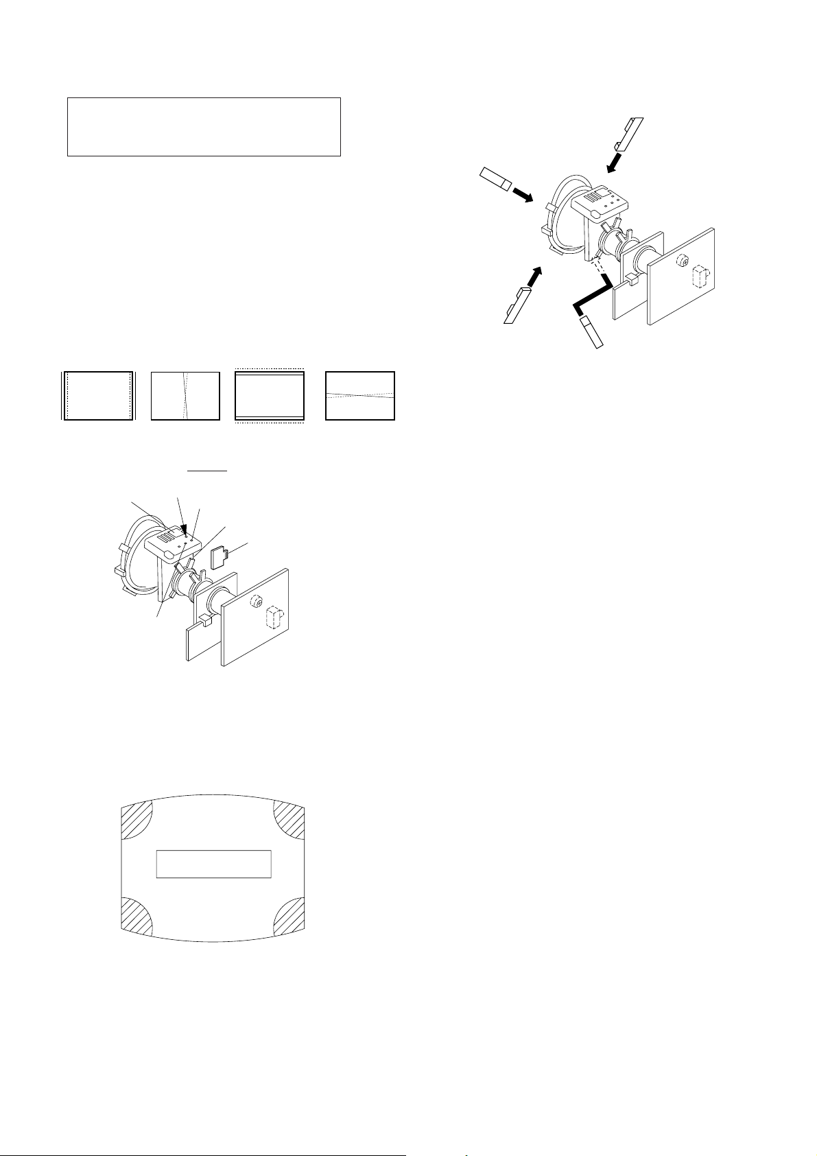
• REMOVAL OF ANODE-CAP
Note:
• After removing the anode, short circuit the anode of the picture tube and the anode cap to the metal chassis, CRT shield
or carbon paint on the CRT.
• REMOVING PROCEDURES
a
a
1 Turn up one side of the rubber cap in the direction
indicated by the arrow a.
b
b
2 Using a thumb pull up the rubber cap firmly in the direction
indicated by the arrow b.
c
anode button
3 When one side of the rubber cap is separated from the
anode button, the anode-cap can be removed by turning
up the rubber cap and pulling it up in the direction of the
arrow c.
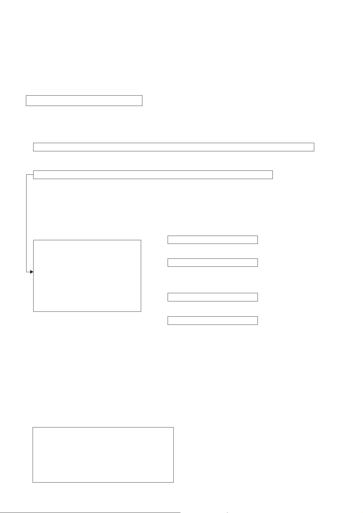
• HOW TO HANDLE AN ANODE-CAP
1 Do not damage the surface of anode-caps with sharp
shaped objects.
2 Do not press the rubber too hard so as not to damage
the inside of anode-cap.
A metal fitting called the shatter-hook terminal is built
into the rubber.
3 Do not turn the foot of rubber over too hard.
The shatter-hook terminal will stick out or damage the
rubber.
– 7 –
Page 9

KV-DA322M64/M66
RM-GA001
2-1. JIGS REQUIRED FOR SERVICING
DESCRIPTION QUANTITY PART NO. REMARK
TOOL(50P-A),SERVICE 1 3-702-765-01 For A to BH1 board extension
SECTION 2
SERVICE JIG
SAMPLE
WL Board
DL Board
SECTION 3
CIRCUIT BOARDS LOCATION
C Board
H2 Board
BH1 Board
A Board
J1 Board
D Board
BP1 Board
H3 Board
VM1 Board
BC1 Board
F1 Board
– 8 –
Page 10

KV-DA322M64/M66
SECTION 4
ADVANCE OPERATION
4-1. "RESET" FUNCTION
1. Purpose
If a customer faces some setting problem that cannot be solved, using the "RESET" function some items will be
reset to its original setting or factory setting (shipping condition)
2. How to Operate
The following is to show on how to access to the "RESET" Function:-
User selection = press 'WEGA GATE' t selectt 'SETTING' t go to 'SETUP' page t select 'FACTORY
SETTINGS' t select 'YES'
3. Subsequent of Operation
RM-GA001
Sequential to the resetting operation, TV set would shut down once and automatically turn on again. The power-off
duration is expected to be about 500msec. Initial Setup Menu is displayed.
As a result, some items will be reset to their initial conditions (shipment condition) wheareas some others remain
at the last user selection.
Items that remain at the last user selection
Program No., PICTURE POSITION (included PICTURE
ROTATION and PICTURE V-POSITION), OSD Language, Fine
tuning,TV System, Skip, Program label, Program sorting, Video
label.
Reset Items
Category Default Category Default
Video input RF user last setting
Main Volume 25
DRC-MF DRC1250
Picture mode VIVID
3D Intelligent Picture ON
Sound mode DYNAMIC
Intelligent volume OFF
Surround OFF
Wide mode 4.3
Auto wide ON
Twin OFF
Program Index OFF
* Program Block Reset particular displayed
channel to unblock
WEGA Theatre Setup
Direct Input HD/DVD 1
Speaker Main
Game mode OFF (Video) *Not available in RF
mode
*Color System RF = Reset to Auto at the particular/displayed Video
= MI Reset to Auto CH, others keep user setting
Eco mode OFF
Wide mode Wide zoom
Auto wide ON
4.3 Default Wide zoom
V Center 00
V Size 00
Mute OFF
OSD Display status OFF
Center-in volume 25
Initial setup menu Reactivate/ON
Twin size Center
*= Will reset only if watched/displayed during RESET operation
- For Multi model only
– 9 –
Page 11

KV-DA322M64/M66
RM-GA001
SECTION 5
SET-UP ADJUSTMENTS
The following adjustments should be made when a complete
realignment is required or a new picture tube is installed.
Perform the adjustments in order as follows :
1. Beam Landing
2. Convergence
3. Focus
The controls and switch should be set as follows unless
otherwise noted:
4. G2(SCREEN)
5. White Balance
Picture Control....................................."NORMAL"
Brightness Control..............................."NORMAL"
Note : Test Equipment Required.
1. Pattern Generator 5. Oscilloscope
2. Degausser 6. Landing Checker
3. DC Power Supply 7. XCV Adjuster
4. Digital Multimeter
......................................................................................................................................................................................................................
Preparation :
•Feed in the white pattern signal.
6. Then move the DY forward and adjust so that the entire
screen becomes green.
• Before starting, degauss the entire screen with the
degausser.
• In order to reduce the geomagnetism on the set's picture
tube, face it east or west.
5-1. BEAM LANDING ADJUSTMENT
1. Input a raster signal with the pattern generator.
2. Loose the deflection yoke(DY) mounting screw, and set
the purity control to the center as shown below:-
Purity control
3. Position Neck Assy as shown below:-
Neck assy
(For 34")
Neck assy
(For 29" and 32")
Align the edge of
the neck assy with
the edge of the G2 grid.
G2G1 G3
4. Set the raster signal of the pattern generator to green.
5. Move the DY backward and adjust the purity control so
that green is in the center and blue and red are at the
sides evenly.
7. Now switch over raster signal to red then blue and
confirm the condition.
8. When the position of the DY is determined, tighten it with
the DY mounting screw.
9. If the beam does not land correctly in all the corners of
the screen, use magnet disc to correct it.
Purity control
corrects this area.
b
c
Deflection yoke positioning
corrects these areas.
a
d
a
d
b
Disk magnets or rotatable
disk magnets correct these
areas (a-d).
c
Red
Blue
Green
– 10 –
Page 12

KV-DA322M64/M66
RM-GA001
5-2. CONVERGENCE ADJUSTMENT
Preparation:
• Before starting, perform FOCUS adjustment.
• Receive dot/cross hatch pattern.
• Picture Mode "CUSTOM" (PIC 90%, BRT 50%,
COL 50%, HUE 50%, SHP 50%).
a) Vertical Static Convergence
Center dot
R G B
R
G
B
4 pole
magnet
Y magnet
RV9001
4-pole
b) Horizontal Static Convergence
If the blue dots does not converge with the red and
green dots, use the 6 pole magnet to adjust in
the manner described below:-
RG B R G B R GB
RB
G
RG
6 Pole
Magnet
GB
RB
6 Pole Magnet
Purity
C Board
1. (Moving vertically), adjust the 4 pole magnet to converge
red, green and blue dots in the center of
the screen.
2. Tilt the 4 pole magnet and adjust static convergence
to open or close the 4 pole magnet.
3. When the 4 pole magnet is moved in the direction of
arrow A and B, the red, green and blue dots moves
as shown below:-
a
A
B
B
B
G
R
b
B
G
R
Moved RV9001 (H.STAT)
DY pocket
4 Pole Magnet
4 Pole
Magnet
c) Y Separation axis correction magnet adjustment.
1. Receive cross hatch signal.
2. Set Picture to "MINIMUM", Brightness to
"STANDARD".
3. Adjust the Y separation axis correction magnet on
the Neck Assembly so that the horizontal lines at
the top and bottom of the screen are straight.
Blue
Neck assy Neck assy
Red
Red
Blue
RGGRB
Red
B
VM1 Board VM1 Board
Blue
– 11 –
Page 13
KV-DA322M64/M66
RM-GA001
d) Convergence Rough Adjustment
Preparation:
• Before starting this adjustment, adjust the
horizontal and vertical static convergence.
Input cross hatch pattern.
i) TLH
Adjust the horizontal convergence of red and blue
dots by inserting TLH Correction Plate to the DY
pocket(left or right).
ii) YCH
Adjust YCH to balance Y axis.
iii) TLV
Adjust the vertical convergence of red and blue dots.
iv) XCV
Adjust XCV to balance X-axis
B
R
TLH
RB
YCH
ON DY:
B
R
TLV
Fix a Permaloy Assy Correction
to the misconverged
a
d
Permalloy assembly
R
B
a to d: Piece B(120), Convergence Correct
or
b
c
Permaloy Assy Correction
XCV
H-TRAP
XCV
YCH
TLV
DY pocket
TLH Plate
e) Screen Corner Convergence
Affix a Piece B(120), Convergence Correct/Permaloy
Assy
Correction to the misconverged areas.
.
ba
a-d : screen-corner
misconvergence
cd
– 12 –
Page 14

KV-DA322M64/M66
RM-GA001
5-3. FOCUS ADJUSTMENT
FOCUS adjustment should be completed before White
Balance adjustment.
1. Receive digital monoscope pattern.
2. Set Picture Mode to "STANDARD".
3. Adjust focus VR so that the center of the screen
becomes just focus.
4. Change the receiving signal to white pattern
and blue back.
5. Confirm magenta ring is not noticeable. In case
magenta ring is obvious, then adjust FOCUS VR
to balance magenta ring and FOCUS.
Lead Assy,
Focus
5-5. SUB BRIGHTNESS ADJUSTMENT
1. Set TV to RF Mode.
2. Input PAL monoscope to RF mode (OTHER model) and
NTSC monoscope (NTSC model).
3. Set the following condition:
i) Set "PICTURE MODE" to "CUSTOM" and adjust
PICTURE to 0% and BRIGHTNESS to 50%.
ii) Receive RF PAL monoscope signal
(RF NTSC monoscope: NTSC models)
iii) Adjust Sub BRT (service item COLR 008 SBRT)
to make 10 IRE Slightly glimmer.
iv) Apply the offset steps according to TV size as in Sub
Brightness offset table
Preset constant
Inch R/G B/G
34" 0.745 0.905
32" 0.775 0.915
29" 0.790 0.903
Sub Brightness offset
Inch Offset
34" Adjusted + 3 Steps
32" Adjusted + 3 Steps
29" Adjusted + 6 Steps
Focus
G2 Adjustment
FLYBACK TRANSFORMER (T6805)
5-4. G2 (SCREEN) ADJUSTMENTS
1. Set the following condition:
- Picture and Brightness to "STANDARD".
- TV to Video mode.
- WHBL 16 "RGBB" to 01.
2. Connect R,G,B of the C board cathode to
oscilloscope.
3. Adjust Brightness to obtain the cathode value
to the value stated below.
Cathode setting voltage:
170 V ± 2 (VDC)
4. Adjust SCREEN VR on the FBT until the scanning line
disappears.
5. Finally set WHBL 016 "RGBB" back to 00.
5-6. WHITE BALANCE ADJUSTMENT
1. Set to Service Mode.
2. Input white raster signal using signal generator.
3. Set the following condition:
i) Receive 100 IRE PAL white signal.
ii) Set to "VIVID" mode.
SADJ 003 COL 60 ➔ 00
iii) Adjust White Balance
COLR 003 GDRV
004 BDRV
006 GCUT
007 BCUT
4) i) Receive PAL ALL White signal (10 uit)
ii) Set to "VIVID" mode
SADJ 003 COL 00 ➔ 100
iii) Adjust color offset
MCP 010 CBOF
011 CROF
– 13 –
Page 15

KV-DA322M64/M66
oNemaNtiB
CRD
golanAIVD
CY/VC/SB/FRi084-PMOCp675/p084p027i0801rehtOCRDp084p027i0801AGV
01FOBC2-7detsujdA4-detsujdA4-detsujdA2+detsujdA2+detsujdA432383230434
11FORC2-7detsujdA5-detsujdA3-detsujdA3+detsujdA3+detsujdA738334838484
oNemaNtiB
BGR/CSTA/latigiD
SM
niwT
CRDp084p027i0801
01FOBC2-73+detsujdA1+detsujdA6-detsujdA5+detsujdA043+detsujdA
11FORC2-77+detsujdA7+detsujdA0+detsujdA31+detsujdA842-detsujdA
RM-GA001
iv) Apply the offset steps according signal as in Ta b le below : White Balance Offset
– 14 –
Page 16
SECTION 6
CIRCUIT ADJUSTMENTS
6-1. ADJUSTMENTS WITH COMMANDER
Service adjustments to this model can be performed using the supplied remote commander RM-GA001.
a. ENTERING SERVICE MODE
With the unit on standby
t [DISPLAY] t 5 t [VOL $+% ] t [POWER]
This operation sequence puts the unit into service mode.
This screen display is:
item no. service data NVM service field channel no./
category in decimal item name in decimal NG command frequency video input name
WHBL 000 WBP 000 x SERVICE 50 S VIDEO 1
KV-DA322M64/M66
RM-GA001
release ID version in binary for factory color system (decimal)
CGA01 0.16M 0000 0000 FF FF NTSC3 00100
S_ _ : for SONY
A_ _ : for AIWA
L_ _ : BX1L Full
B_ _ : BX1L Basic
D_ _ : DVD Combo
C_ _ : CX1
Z_ _ : Sound special
_ _ _01 : Serial no. of the M/P release for each
_ _ _10 ~: use for FY04 BX1
_ _SB : Sub Hercules
software service data reserved power on time
For BP1 Board Version; and PF Engine Version;
Category and release ID will be different.
The rest are the same.
destination
BP1 Board Version
category in decimal name
SUBP 000 IDXH
release ID version
CBP01 0.06
PF Engine Version
category in decimal name
9090 000 UOF
release ID version
PF 0018M
item no. item
software
item no. item
software
b. METHOD OF CANCELLATION FROM SERVICE MODE
Set the standby condition (Press [POWER] button on the commander), then press [POWER] button again, hereupon it becomes
TV mode.
c. METHOD OF WRITE INTO MEMORY
1. Set to Service Mode.
2. Press 1 (UP) and 4 (DOWN), to select the adjustment item.
3. Change item by pressing 3, 6.
4. Press [MUTING] button to indicate WRITE on the screen.
5. Press - button to write into memory.
1, 4 Select the adjustment item.
r
3, 6 Raise/lower the data value.
r
[MUTING] Writes.
r
- Executes the writing.
– 15 –
Page 17

KV-DA322M64/M66
RM-GA001
d. MEMORY WRITE CONFIRMATION METHOD
1. After adjustment, pull out the plug from AC outlet, and then plug into AC outlet again.
2. Turn the power switch ON and set to Service Mode.
3. Call the adjusted items again to confirm adjustments were made.
e. OTHER FUNCTION VIA REMOTE COMMANDER
7, - All the data becomes the values in memory.
8, - All user control goes to the standard state.
Display, - Service data initialization (Be sure not to use usually.)
2, 5 Select Device or Category
6-2. ADJUSTMENT METHOD
Item Number 000 HPOS
This explanation uses H POSITION as an example.
1. Select "000 HPOS" with the 1 and 4 buttons, or 2 and 5.
2. Raise/lower the data with the 3 and 6 buttons.
3. Select the optimum state. (The standard is IF for PAL reception.)
4. Write with the [MUTING] button. (The display changes to WRITE.)
5. Execute the writing with the - button. (The WRITE display will be changed to red color while executing, and back to
SERVICE.)
Example on screen display :-
GREEN
WHBL 000 WBP 000 SERVICE 50 VIDEO 1
Adjusted with [3] and [6] buttons.
GREEN
WHBL 000 WBP 000 WRITE 50 VIDEO 1
write with [MUTING].
RED
WHBL 000 WBP 000 WRITE 50 VIDEO 1
Write executed with [0].
The WRITE display
then returns to green
SERVICE
Use the same method for all Items. Use 1 and 4 to select the adjustment item, use 3 and 6 to adjust, write with
[MUTING], then execute the write with -.
Note : 1. In [WRITE], the data for all items are written into memory together.
2. For adjustment items that have different standard data between 50Hz or 60Hz, be sure to use the respective input
signal after adjustment.
– 16 –
Page 18

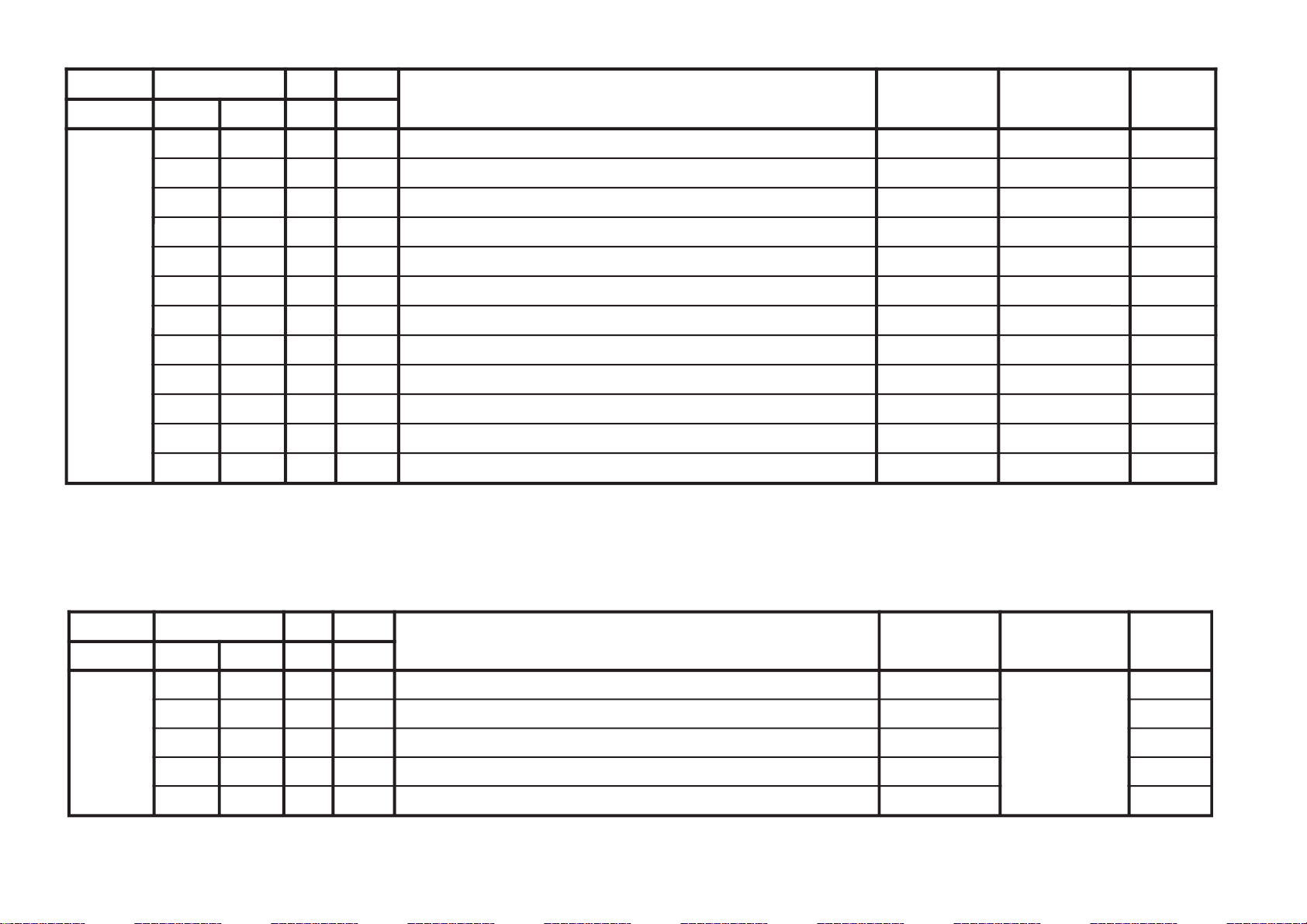
JVTytilanoitcnuF.tinIegnaRnoitcnuFetoN&elbaTemaNeciveDnommoC )deliateD(eulaVlaitinI
yrogetaC.oNemaNceDceD srehtOVUY)VT(LAP)VT(CSTN)VT(MACES)oediV(LAP)oediV(CSTN)oediV(MACESTUPNI-SMACESCSTN
CY000YLDY210510yaleD-Y TUPNI-S/VUY+)OEDIV/VT(*)MACES/CSTN/LAP(cimsoC
0011606001* 6001
100TAMC000300xirtaM)ASU/napaJ(CSTNroMACES-LAP 00
200LCA100100gnitimiLroloCcitamotuA 10
300BC000100ycneuqerFretneCssapdnaBamorhC )xif0:oediV*(VThtiwylnodilav00
400OBS100300tesffOkcalBMACES 10
500ESHC100300ytivitisneStnedICSTN/LAP 30
600OLC000100retliF)lleB(ehcolCfoycneuqerFretneC 00
700PRTC000100edoMparTamorhC srehto/MACES
00
10
800SPB000100eniLyaleDdnab-esaBamorhCfossapyB srehto/CSTN
00
*
900OCF000100nOroloCdecroF 00
Adjustment Item Ta ble (Main Micon)
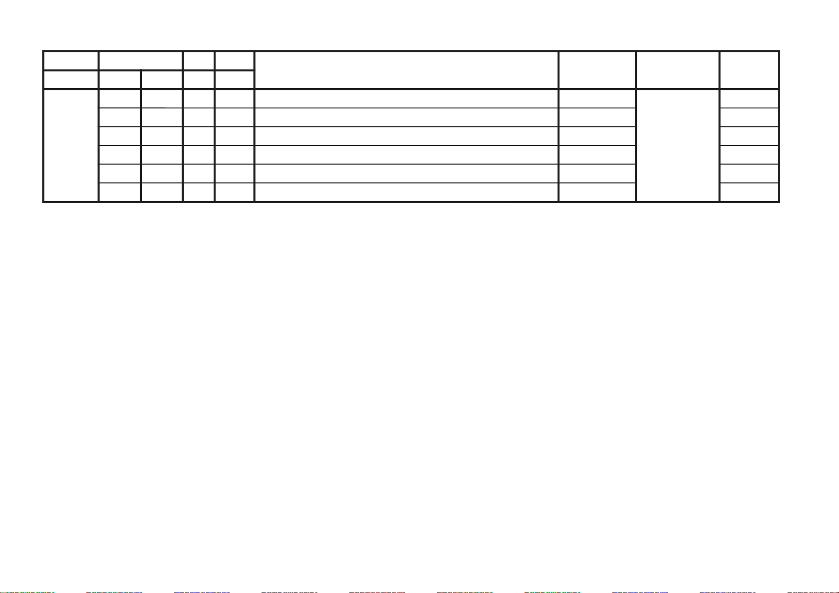
JVTytilanoitcnuF.tinIegnaRnoitcnuFetoN&elbaTemaNeciveDnommoC )deliateD(eulaVlaitinI
yrogetaC.oNemaNceDceD
pmeTloC
)rehtoHGIH(
pmeTloC
)rehtoWOL(
pmeTloC
)rehtoMRON(
pmeTloC
)VUYHGIH(
pmeTloC
)VUYWOL(
pmeTloC
)VUYLAMRON(
pmeTloC
)BGRHGIH(
pmeTloC
)BGRWOL(
pmeTloC
)BGRMRON(
0edomciP1edomciP2edomciP
LBHW000PBW000300)woL:3,2,lamroN:1,hgiH:0(gnitteSpmeTroloC edoMerutciPcimsoC
001010
JVTytilanoitcnuF.tinIegnaRnoitcnuFetoN&elbaTemaNeciveDnommoC)deliateD(eulaVlaitinI
yrogetaC.oNemaNceDceD
edomciP
0
edomciP
1
edomciP
2
VToediVlamroN
)3:4(
DHxednI/niwT
paP/
rehtO
JDAS000EUHS700510euH-buS oediV/VT
4080
100FOIP000700)%57(ocE*02/)atad-02(*erutciP(tesffOerutciP REHTO/ITLUM/LAMRON/SMenignEFP
** * *
200CIP130721
0[lortnoCerutciP
-
])CSTN(36-0,)ITLUM(001
)ataDteseRresU=lanosreP:AG(ledoMerutciP
0010705
300LOC130721])CSTN(36-0,)ITLUM(001-0[lortnoCroloC )ataDteseRresU=lanosreP:AG(ledoMerutciP
060605
400TRB130721])CSTN(36-0,)ITLUM(001-0[lortnoCssenthgirB )ataDteseRresU=lanosreP:AG(ledoMerutciP
050505
500EUH130721])CSTN(36-0,)ITLUM(001-0[lortnoCeuH )ataDteseRresU=lanosreP:AG(ledoMerutciP
050505
600PHS130721]])CSTN(36-0,)ITLUM(001-0[lortnoCssenprahS )ataDteseRresU=lanosreP:AG(ledoMerutciP
050505
NOTE
a) In the initial value (detailed) colomn, the data after the slash mark ("/") refers to NTSC model data.
No ("/") means data is common for Multi and NTSC model.
b) Item remarked "*" and "**", please refer page 32 for the data.
c)
shaded items are no data.
d) Standard data listed on the Adjustment Item Tab le are reference values, therefore it may be different for each model and for each mode.
e) Note for the Different Data those are the standard data values written on the microprocessor. Therefore, the data values of the models are stored respectively in the memory.
In the case of a device replacement, adjustment by rewriting the data value is necessary for some items.
f) Multi ver1.07.
– 17 –
KV-DA322M64/M66
RM-GA001
Page 19

– 18 –
JVTytilanoitcnuF.tinIegnaRnoitcnuFetoN&elbaTemaNeciveDnommoC)deliateD(eulaVlaitinI
yrogetaC.oNemaNceDceD 0506srehtOVUYVToediVtxeteleTpi-VTlangiSoN
CNYS000SYS000100tupnICNYSYnonoitazinorhcnyS cimsoC00
100OF
000300tnatsnoCemiT1esahP
)FR(langisoNrogninuTotuA/txeteleT/oediV/FFOPIVT/NOPIVT
3030100000
200DIV000100edoMtnedIoediV 06/05
0000
300LSF000100cnySlacitreVrofleveLgnicilSdecroF 00
400LSS000100rotarapeScnySleveLgnicilS 06/05
0000
500DIVS100700noitacifitnedIoediVrofnoitceleSecruoS srehtO/VUY
0000
600FROF200300ycneuqerFdleiFdecroF 20
700KVM000100gniyeKnoisiVorcaM 10
JVTytilanoitcnuF.tinIegnaRnoitcnuFetoN&elbaTemaNeciveDnommoC )deliateD(eulaVlaitinI
yrogetaC.oNemaNceDceD
srehtOBGReviLVT
)nyD(
VT
)srehtO(
oediV
)nyD(
oediV
)srehtO(
pmeTroloC
)HGIH(
pmeTroloC
)srehtO(
roloC
)WOL(pmeT
pmeTroloC
)LAMRON(
TCIP000AFC000300edoMretliFbmoC cimsoC00
JVTytilanoitcnuF.tinIegnaRnoitcnuFetoN&elbaTemaNeciveDnommoC)deliateD(eulaVlaitinI
yrogetaC.oNemaNceDceD VUYVToediV
WS0002VC000100noitceleSlangiStupnI2SBVC cimsoC00
100OVS10030084@niPISBVC/OVS/OVFIfonoitcnuFVUY/oediV/VT
201010
200LFD000100noitcetorPhsalF 10
300FTNI000100langisecafretniVUYfoytiraloP/edutilpmA 00
KV-DA322M64/M66
RM-GA001
Page 20
– 19 –
JVTytilanoitcnuF.tinIegnaRnoitcnuFetoN&elbaTemaNeciveDnommoC
yrogetaC.oNemaNceDceD
MEDS000SWMF000300rotaludomeDMFrofnoitceleSwodniW cimsoC20
100SSQ100100 )metsysMitlumAGrofA/N(edoMreifilpmA)SSQ(dnuoStilpSisauQ *
200BPB000100retliFssapdnaBdnuoSfossapyB 00
300OLMA000100dnuoSMAroflangiStuptuOoiduA 00
400CVPH000100lortnoCemuloVenohPdaeH 00
JVTytilanoitcnuF.tinIegnaRnoitcnuFetoN&elbaTemaNeciveDnommoC
yrogetaC.oNemaNceDceD
FIV000DFIO630360rotaludomeDFItesffO cimsoC63
100TCGA130360revo-ekaTCGA 72
200MTS000100edoMgninuThcraeS 10
300DG000100langiS1SBVCnoyaleDpuorG 00
400SCGA100300deepSCGAFI 10
500IFF000100LLPFIretliFtsaF 00
600IANL100100eulavlaitinitibANLpmAFR 00
700TANL591552leveLdlohserhTpmAFR 591
800NSNL400700dlohserhTleveLNSpmAFR 40
900DSNL200700dlohserhTporDleveLNSpmAFR 10
010XENL610360gnimiTporDNSkcehcpmAFR 03
110RTHC840721edoMresUpmAFRtesotgrPotuAretfadlohserhTlennahC 52
Note: For remark "*", refer to page 32.
KV-DA322M64/M66
RM-GA001
Page 21
JVTytilanoitcnuF.tinIegnaRnoitcnuFetoN&elbaTemaNeciveDnommoC
yrogetaC.oNemaNceDceD
TXT000VXT930360spilihProfnoitisoPlacitreVtxeteleT ossaciP93
100DHT010721tfihSegdEevitcAcnys-HtxeteleT 11
200RBT820130)edomllufrof(ssenthgirBBGRtxeteleT 82
300MRBT310130)edomXIMrof(ssenthgirBBGRtxeteleT 31
400DTSN000100)edomXIMotog:1,TXTlecnac:0(langiSdradnatSnoNfoM/C 00
500QCA000100)1-LAP,0-otuA(noitisiuqcAtxeteleT 00
(only for model with teletext function)
– 20 –
KV-DA322M64/M66
RM-GA001
Page 22

JVTytilanoitcnuF.tinIegnaRnoitcnuFetoN&elbaTemaNeciveDnommoC )deliateD(eulaVlaitinI
yrogetaC.oNemaNceDceD )oruE(L-VTVToediVffOWOW/SRSdnuorrusurToeretsIonomI
PSDS000LBB000510ruotnoCEBB dnuoS
PSD
*
100HBB000510ssecorPEBB *
200WLBB000510tesffOruotnoCEBB *
300FOVS000510tesffOemuloVedoMtceffE/dnuorruS onomI/oeretsI/dnuorrusurT/)WOW/SRS(ffO
4090406040
400DAL000130tsujdAleveLredoceD 40
500MAL000130tsujdAleveLonoM 40
600NAL000130tsujdAleveLmaciN *
700SAL000130tsujdAleveLPAS 80
800AAL000130tsujdAleveLCDA oediV/Lnon-VT/L-VTI)oruEnoN(oediV/vT
717100
900FES300700tceffEoeretS/onoMelbidercnI onomI/oeretsI
5030
010SAB000510tesffOssaBniaM *
110ERT000510tesffOelberTniaM *
2101QE000510tesffO)zH001(dnaBlennahCniaMrezilauqE *
3102QE000510tesffO)zH003(dnaBlennahCniaMrezilauqE *
4103QE000510tesffO)zH0001(dnaBlennahCniaMrezilauqE *
5104QE000510tesffO)zH0003(dnaBlennahCniaMrezilauqE *
6105QE000510tesffO)zH0008(dnaBlennahCniaMrezilauqE *
710TCFB500700lortnoCEBBdnaBUD,EBD 50
810NECS100510lortnoCretneCD3SRS 40
910APSS000510lortnoCecapSD3SRS 10
020WHBB000510edomWOWnitesffossecorpEBB *
120ERTS200700edomdnuorrusroftesffOelberT 10
220THBB000510edomVTnitesffOEBB 00
320ERTT200700edoMVTnitesffOelberT 30
4201QEC800510)zH001(ataDdnaBrezilauqEnI-retneC 60
5202QEC800510)zH003(ataDdnaBrezilauqEnI-retneC 90
6203QEC800510)zH0001(ataDdnaBrezilauqEnI-retneC 01
7204QEC800510)zH0003(ataDdnaBrezilauqEnI-retneC 01
8205QEC800510)zH0008(ataDdnaBrezilauqEnI-retneC 70
– 21 –
KV-DA322M64/M66
RM-GA001
Page 23
– 22 –
JVTytilanoitcnuF.tinIegnaRnoitcnuF etoN&elbaTemaNeciveDnommoC
yrogetaC.oNemaNceDceD
CEDS000UTPS300510noitcetedreirracPASrofdlohserhTreppU dnuoS
PSD
80
100LTPS600510noitcetedreirracPASrofdlohserhTrewoL 51
200HTPS000130PASfoetumotuarofdlohserhTesioN 00
300YHPS400510PASfoetumotuarofezissiseretsyH 30
400HTMF000130dradnats2AMFni2CSfoetumotuarofdlohserhTesioN 81
500YHMF400510dradnats2AMFni2CSfoetumotuarofezissiseretsyH 70
600ELIN001552)PEDD(timilrorrerewolMACIN 05
700EUIN002552)PEDD(timilrorrereppuMACIN 002
800DMPE100300)PEDD(gnimmargorPysaECEDMED
1=1tiB3POdna0=SDTSdna0=DMPEfI
revoekatlliwyrogetacCKDSdnaelbasiDsiyrogetacCEDS
*
900SDTS910130sedomSSSdnaDSArofdexelpitlumstiB *
010AMVO100100noitpadanoitaludomrevoMF 00
110WBLF000300htdiwdnabretlifrotaludomedMA/MF 30
210DMDI000300edomSSSnideepstnediMF 00
310TMVO100200lanimonotevitalerdlohserhtlevelnoitaludomrevO 30
410IXCD000100retrevnIlortnoCgnilacSOXCDMACIN *
510GXCD000700niaGlortnoCgnilacSOXCDMACIN *
610LLCD110510)L(timiLlortnoCgnilacSOXCDMACIN 00
710HLCD000130)H(timiLlortnoCgnilacSOXCDMACIN *
810RKDI100300DTSMnaeroKrofgnittesDOMDI 00
JVTytilanoitcnuF.tinIegnaRnoitcnuF etoN&elbaTemaNeciveDnommoC
yrogetaC.oNemaNceDceD
CKDS000LLNK000552etyBrewoLdlohserhTrewoLteDesioNnaeroK
1=1tiB3POdna0=SDTSdna0=DMPEfI
revoekatlliwyrogetacCKDSdnaelbasiDsiyrogetacCEDS
100HLNK210552etyBrehgiHdlohserhTrewoLteDesioNnaeroK
200LHNK000552etyBrewoLdlohserhTreppUteDesioNnaeroK
300HHNK020552etyBrehgiHdlohserhTreppUteDesioNnaeroK
400CILK060552tnuocgniniatniamDItoliPtsoLnaeroK
500MILK100721reilpitlumtnuocgniniatniamDItoliPtsoLnaeroK
600CDSK600552tnuoCtceteDoeretSnaeroK
Note: For remark "*", refer to page 30~31.
(only applicable for Korea model)
KV-DA322M64/M66
RM-GA001
Page 24
JVTytilanoitcnuF
.tinIegnaRnoitcnuFetoN&elbaTeciveD
emaN
nommoC )deliateD(eulaVlaitinI
yrogetaC.oNemaNceDceD
0RN1RN2RN3RN4RN0CSTN1CSTN1RN-FR-FR
1CSTN
-VT
LAP
-VT
CSTN
OEDIV
LAP-
-OEDIV
CSTN
RN3
000TED3000700TEDD3
/1tN/0TN/3RN/2RN/1RN/0RN
1CSTN-FR/1RN-FR
bmoCD3
707070707070707070
100ROC3000100RROCRND3
/1tN/0TN/3RN/2RN/1RN/0RN
1CSTN-FR/1RN-FR
100000000010000000
200CFA000300NIAGCFA
/1tN/0TN/3RN/2RN/1RN/0RN
1CSTN-FR/1RN-FR
303030303030303030
300GEH000300NIAGAHNEH 00
400RNC2000510MILRNCD2&KRNC-D2
/1tN/0TN/3RN/2RN/1RN/0RN
1CSTN-FR/1RN-FR
003050509020003000
500CNY000700MILCN-Y;RELLECNACESIONY
/1tN/0TN/3RN/2RN/1RN/0RN
1CSTN-FR/1RN-FR
003030507020103030
600RNY2000510NIAGRNYD2;KRNYD2
/1tN/0TN/3RN/2RN/1RN/0RN
1CSTN-FR/1RN-FR
000020008010102000
700LNY2000300MILRNYD2
/1tN/0TN/3RN/2RN/1RN/0RN
1CSTN-FR/1RN-FR
002030003020203030
800KLB000300PXEKLB 10
900RNC3000700MILRNCD3
/1tN/0TN/3RN/2RN/1RN/0RN
1CSTN-FR/1RN-FR
000030307000000000
010KNC3000300KRNCD3
/1tN/0TN/3RN/2RN/1RN/0RN
1CSTN-FR/1RN-FR
000000000000000000
110GNC3000700NIAGRNCD3
/1tN/0TN/3RN/2RN/1RN/0RN
1CSTN-FR/1RN-FR
002020207000004000
210RNY3000700MILRNYD3
/1tN/0TN/3RN/2RN/1RN/0RN
1CSTN-FR/1RN-FR
003030606000001000
310KNY3000300KRNYD3
/1tN/0TN/3RN/2RN/1RN/0RN
1CSTN-FR/1RN-FR
001020000000001030
410GNY3000700NIAGRNYD3
/1tN/0TN/3RN/2RN/1RN/0RN
1CSTN-FR/1RN-FR
002050606000001000
510YLDY000821YALEDTUPTUOY
/LAP-DIV/CSTN-VT/LAP-VT
CSTN-S/LAP-S/CSTN-DIV
30706040
610ACI000100OTUAPMALCTNI 10
710MCI000100LAUNAMPMALCTNI 00
810HNEC000100AHNEC 10
910KCI000100YEKPMALCTUPNI 10
020KGB000100YEKETAGTSRUB 10
120LSS000100FPLPESCNYS 00
– 23 –
KV-DA322M64/M66
RM-GA001
Page 25

KV-DA322M64/M66
JVTytilanoitcnuF
.tinIegnaRnoitcnuFetoN&elbaTeciveD
emaN
nommoC )deliateD(eulaVlaitinI
yrogetaC.oNemaNceDceD
0RN1RN2RN3RN4RN0CSTN1CSTN1RN-FR-FR
1CSTN
-VT
LAP
-VT
CSTN
OEDIV
LAP-
-OEDIV
CSTN
-S
LAP
-S
CSTN
lamroN
)3:4(
DHxednI/niwT
paP/
rehtO
RN3
220RCEV000300EROCAHNEV
/1tN/0TN/3RN/2RN/1RN/0RN
1CSTN-FR/1RN-FR
bmoCD3
001010300000101010
320GEV000300NIAGAHNEV
/1tN/0TN/3RN/2RN/1RN/0RN
1CSTN-FR/1RN-FR
000010100000100010
420NEV000300LNAHNEV
/1tN/0TN/3RN/2RN/1RN/0RN
1CSTN-FR/1RN-FR
000010100000100010
5201PMA0007001PMADH
/1tN/0TN/3RN/2RN/1RN/0RN
1CSTN-FR/1RN-FR
606060606060606060
620VGDH000130VNIAGDH
/1tN/0TN/3RN/2RN/1RN/0RN
1CSTN-FR/1RN-FR
818181818181818181
7202PMA0007002PMADH
/1tN/0TN/3RN/2RN/1RN/0RN
1CSTN-FR/1RN-FR
606060606060606060
8201GDH0001301NIAGDH
/1tN/0TN/3RN/2RN/1RN/0RN
1CSTN-FR/1RN-FR
313131313131313131
9203PMA0007003PMADH
/1tN/0TN/3RN/2RN/1RN/0RN
1CSTN-FR/1RN-FR
505050505050105050
0302GDH0001302NIAGDH
/1tN/0TN/3RN/2RN/1RN/0RN
1CSTN-FR/1RN-FR
404040404040104040
130PLSC000510PLSSCA&PLSMCA
/1tN/0TN/3RN/2RN/1RN/0RN
1CSTN-FR/1RN-FR
514101015101010101
230PLSY000510PLSSYA&PLSMYA
/1tN/0TN/3RN/2RN/1RN/0RN
1CSTN-FR/1RN-FR
515101400141414141
330SMCA000510TESFMCA&TESEMCA
/1tN/0TN/3RN/2RN/1RN/0RN
1CSTN-FR/1RN-FR
510101015151510151
430SSCA000510TESFSCA&TESESCA
/1tN/0TN/3RN/2RN/1RN/0RN
1CSTN-FR/1RN-FR
510101015151010101
530SMYA000510TESFMYA&TESEMYA
/1tN/0TN/3RN/2RN/1RN/0RN
1CSTN-FR/1RN-FR
511101015151511151
630SSYA000510TESFSYA&TESESYA
/1tN/0TN/3RN/2RN/1RN/0RN
1CSTN-FR/1RN-FR
511141015111014101
730LSCB000510PLSSCB&PLSMCB
/1tN/0TN/3RN/2RN/1RN/0RN
1CSTN-FR/1RN-FR
51
0101015141510151
830LSYB000510PLSSYBPLSMYB
/1tN/0TN/3RN/2RN/1RN/0RN
1CSTN-FR/1RN-FR
510101015141310121
930SMCB000510TESFMCB&TESEMCB
/1tN/0TN/3RN/2RN/1RN/0RN
1CSTN-FR/1RN-FR
510101015151010101
040SSCB000510TESFSCB&TESESCB
/1tN/0TN/3RN/2RN/1RN/0RN
1CSTN-FR/1RN-FR
510101015151010101
140SMYB000510TESFMYBTESEMYB
/1tN/0TN/3RN/2RN/1RN/0RN
1CSTN-FR/1RN-FR
515101015151515151
240SSYB000510TESFSYBTESESYB
/1tN/0TN/3RN/2RN/1RN/0RN
1CSTN-FR/1RN-FR
515101015151015101
340MCEC000700PMCEC
/1tN/0TN/3RN/2RN/1RN/0RN
1CSTN-FR/1RN-FR
704070704040407040
440MCSC000510PMCSC
/1tN/0TN/3RN/2RN/1RN/0RN
1CSTN-FR/1RN-FR
510151510000005100
540VH1F000510REV1F&REH1F
/1tN/0TN/3RN/2RN/1RN/0RN
1CSTN-FR/1RN-FR
508050505050508050
640FERM000510FERM
/1tN/0TN/3RN/2RN/1RN/0RN
1CSTN-FR/1RN-FR
207040404010607060
740YEDC000300EYEDC
/1tN/0TN/3RN/2RN/1RN/0RN
1CSTN-FR/1RN-FR
203020202020003000
840YEDY000300EYEDY
/1tN/0TN/3RN/2RN/1RN/0RN
1CSTN-FR/1RN-FR
203020202020003000
940SAMH000700TUOKSAM-H
00
050SAMV000130TUOKSAM-V
00
RM-GA001
– 24 –
Page 26
GVTytilanoitcnuF
laitinIegnaRnoitcnuFetoN&elbaTeciveD
emaN
nommoC
)deliateD(eulaVlaitinI
yrogetaCoNemaNceDceD
ciP
0edom
ciP
1edom
ciP
2edom
FRtpecxE
0edomciP
FRtpecxE
1edomciP
FRtpecxE
2edomciP
ITL000SFC100100noitceleSretliFruotnoC 10
100CDV100100gniroCtnednepeDoediVedoMerutciP
101010
200MED000100edoMnoitartsnomeD 00
300PDC400700yaleDecnanimuL 40
400KSD000100hctiwSenoTnikSedoMerutciP
000000
500KSA000100noitceleSelgnAenoTnikS 00
600KSW000100noitceleShtdiWenoTnikS 00
700KSS000100noitceleSeziSenoTnikS 00
800RGD100100hctiwStnemecnahnEneerGedoMerutciP
101000
900TGD700700hctiwStnemecnahnEneerGfodlohserhT 70
010RGG000100niaGtnemecnahnEneerG 00
110RGW000100htdiWtnemecnahnEneerG 00
210RGS000100eziStnemecnahnEneerG 00
310SDC100100ssenprahStnednepeDroloCedoMerutciP
101000
410TSC700700ssenprahStnednepeDroloCfodlohserhT 70
510ITC100100tnemevorpmItneisnarTroloCedoMerutciP
101000
610NOB000100noitasnepmoCtesffOkcalBedoMerutciP
000000
710DTB000360htcertSkcalBevitpadAedoMerutciP
000000
810DLN120360reifilpmAytiraeniL-noNedoMerutciP
121200
910WLN700700reifilpmAytiraeniL-noNfohtdiWpetS 70
020DGV130360ammaGelbairaVedoMerutciP
***
120WGV000700ammaGelbairaVfohtdiWpetS 00
220DKP040360edutilpmAgnikaeP)srehtO/VT(*edoMerutciP
*0341 ***
320WKP800510edutilpmAgnikaePfohtdiWpetS 80
320DPS000360noitcerroCssenpeetSedoMerutciP
000000
520DRC050360leveLgniroC)srehtO/VT(*edoMerutciP
*0300* 8100
620WRC900510leveLgniroCfohtdiWpetS 60
720ORC600510edoMoediVroftesffOleveLgniroC 60
820DWL130360noitcerroChtdiWeniL 13
920ITLE100100
ITLelbasiD/elbanE
]noitpo1XC-tsoP[lortnoc
10
– 25 –
KV-DA322M64/M66
RM-GA001
Page 27

JVTytilanoitcnuF.tinIegnaRnoitcnuFetoN&elbaTemaNeciveDnommoC
yrogetaC.oNemaNceDceD
DEFP000DEFP000100edoMecivreSenignEFPenignEFP
JVTytilanoitcnuF.tinIegnaRnoitcnuFetoN&elbaTemaNeciveDnommoC)deliateD(eulaVlaitinI
yrogetaC.oNemaNceDceD 0506
PBUS000HXDI500510noitisoplatnozirohDSOxednIataDtimsnarTossaciPbuSossaciPbuS50
100VXDI740360noitisoplacitrevDSOxednI)06/05(ataDtimsnarTossaciPbuS7474
200BXDI130130ssenthgirbDSOxcednIataDtimsnarTossaciPbuS13
(only applicable for 2 tuners models)
– 26 –
KV-DA322M64/M66
RM-GA001
Page 28

JVTytilanoitcnuF.tinIegnaRnoitcnuFetoN&elbaTemaNeciveDnommoC)deliateD(eulaVlaitinI
yrogetaC.oNemaNceDceD 0506VUYVToediVlangiSoN
SOCS000SYS100100tupnICNYSYnonoitazinorcnyS cimsoCbuS00
100OF000300tnatsnoCemiT1esahP )FR(langisoNrogninuTotuA/VT
003000
200DIV100100edoMtnedIoediV 06/05
0000
300LSF000100cnySlacitreVrofleveLgnicilSdecroF 00
400LSS000100rotarapeScnySleveLgnicilS 06/05
0000
500DIVS000700noitacifitnedIoediVrofnoitceleSecruoS VUY/oediV/VT
000000
600FROF300300ycneuqerFdleiFdecroF 20
700OVS00030084@niPISBVC/OVS/OVFIfonoitcnuF VUY/oediV/VT
000000
800EXDV
000100dnareifilpmaFInoisivneewtebgnilpuocfolortnoC
tiucricnoitasinorhcnys
00
900XDV
000100dnareifilpmaFInoisivneewtebgnilpuoC
tiucricnoitasinorhcnys
00
010YLDY210510tnemtsujdayaled-Y 00
110DFIO630360rotaludomeDFItesffO 63
210TCGA130360revo-ekaTCGA 13
310MTS100100edoMgninuThcraeS 10
410DG000100langiS1SBVCnoyaleDpuorG 00
510SCGA100300deepSCGAFI 10
610IFF000100LLPFIretliFtsaF 00
710SSMC000100tiucrictnedioedivehtroflangistupnicnysfonoitceleS 00
810PMAO300300edutilpmAlangiStuptuOoediV 00
910IAV000100noitcerroCedutilpmAlangiStuptuOImetsyS 00
020SWMF200300rotaludomeDMFrofnoitceleSwodniW 20
120SSQ
000100edoMreifilpmA)SSQ(dnuoStilpSisauQ
)ledoMAGtpecxe(
10
220BPB000100retliFssapdnaBdnuoSfossapyB 00
3202BPB0001002retliFssapdnaBdnuoSfossapyB 00
420TPS000100edomkcirtecnamrofrepcnyS 00
520D2E000100nipMEEDUAnolangistuptuooiduafonoitceleS 00
620CVPH000100lortnoCemuloVenohPdaeH 00
720GSD000100stuptuooiduaotstupnioiduamorfniaG 00
820DSV100100elbasidnacslacitreV 00
920ESHC100300ytivitisneStnedICSTN/LAP 30
– 27 –
(only applicable for 2 tuners models)
KV-DA322M64/M66
RM-GA001
Page 29

– 28 –
JVTytilanoitcnuF.tinIegnaRnoitcnuFetoN&elbaTemaNeciveDnommoC
yrogetaC.oNemaNceDceD
VTH100XAMV000360)XAMV+53=XAM(leveLemuloVmumixaM leveLemuloV00
200INIV520130norewoptaleveLemuloVlaitinI leveLemuloV52
300YBTS000100 )YBTSsyawla=1,sutatsrewoptsalehtwollof=0(sutatSrewoPtsaL rewoPtsaL00
400GRPI100721)sledomitluMrofylno(norewoptarebmuNmargorPlaitinI
ot0:lageL(rebmuNmargorP
)1otteserlliw,001>fi,99
10
JVTytilanoitcnuF.tinIegnaRnoitcnuFetoN&elbaTemaNeciveDnommoC
yrogetaC.oNemaNceDceD
MTPO000THSA600700)nim5*atad(remitffotuhsotuA 00
100ETUM000100)delbane=1(hctiwSetuMlangiSoN 00
200LUFR510510)hf0nehwelbasiD(dekcolnUretfaretnuoCegnahClangiSFR 40
300KLFR510510)hf0nehwelbasiD(dekcoLretfaretnuoCegnahClangiSFR 00
400GNAL000300noitidnocgnippihsegaugnalDSO *
500TXTH000100wsrotarapescnyS cimsoC00
600SSMC000100wscnyS cimsoC10
700OXCD060592eulaVOXCD ossaciP*
800CSID821552cedrolocybtsujdaOXCDrofatadOCSIDtegraT 431
900LBXE000510esioNetihWetanimilEotremiTgniknalBdednetxE 01
010SYST000300 )ledoMAG(]M:3,K/D:2,I:1,G/B:0[teseRtseTtaMVNnisySVTeziromeM *
110LBL100100noitidnoclangiSoNtAnoitcudeRssenthgirB 10
210P32100100otuA:1,FFOecroF:0edoMnwoDlluP3/2 enignEFP10
310WSNL100100)ffO:0,otuA:1(noitidnocteseRtseT/gnippihSretsooBlangiS 10
410MTSD000100)elbasid:1,elbane:0(ybdnatSniedompotselbasiD 00
510MPSC000100)elbasid:1,elbane:0(yromeMtsaLrekaepSretneCelbanE 00
610WSRN100200)HGIH-2,woL-1,FFO-0(noitidnoCgnippihSretfagnitteSRN *
Note: For remark "*", refer to page 30~31.
KV-DA322M64/M66
RM-GA001
Page 30
JVTytilanoitcnuF.tinIegnaRnoitcnuFetoN&elbaTemaNeciveDnommoC)deliateD(eulaVlaitinI
yrogetaC.oNemaNceDceD srehtOVUY
SUPO000FFOS000100)noCAhtiwybdnats:1,noCAhtiwyromemtsalwollof:0(ffoyatS
100RBCC510130ssenthgirBDSOCC
200HCPS100721noitidnoCgnippihSretfarebmuNlennahC
300ACPS100100)nOelbaC=1(noitidnoCgnippihSretfanoitceleSelbaC
400VUO000100)SUrofylno(slangiStupnIVUnolortnoCtesffO VUY/srehtOcimsoC
5002AFC000100)SUrofylno(nOretliFbmoCdecroF enoncimsoC
(only applicable for NTSC models)
JVTytilanoitcnuF.tinIegnaRnoitcnuFetoN&elbaTemaNeciveDnommoCsrehtOMACESCSTN
yrogetaC.oNemaNceDceD
PVPO000SBPB000100)SBPB(edomoeretstaretlifssapdnabdnuosfossapyB cimsoC00
100CYWB000100)CYMB(metsysroloczHM85.3rofedomCYtahtdiwdnaB 00
200BSO000100)BSO(rotaludomedamorhcfoeslupyektsrublanretnifohtdiW 00
300VUYT000100)VUYTXT(noitcelestuptuoCC/TXT 10
400DCL000100)DCL(edoMDCL 10
500CKB000100noitisoPyeKtsruB )LAP(SREHTO/MACES/CSTN
001000
JVTytilanoitcnuF.tinIegnaRnoitcnuFetoN&elbaTemaNeciveDnommoC
yrogetaC.oNemaNceDceD
BTPO000LLAI000100)MVNnideziromemton(hctiwSetirWdradnatS X
1001BPO000552)detalerlangiSoediV(1noitpO
tibnoitporoF(
otreferatad
)43~33segap
2002BPO000552)detalergnidoceDoeretS(2noitpO
3003BPO000552)suoenallecsiM(3noitpO
4004BPO000552)suoenallecsiM(4noitpO
5005BPO000552)detaleregnaugnaLDSO(5noitpO
– 29 –
KV-DA322M64/M66
RM-GA001
Page 31

KV-DA322M64/M66
RM-GA001
Data Variant depend on models
Category No Name 10+10 10+10 10+10 10+10 10+10
SDSP 000 BBL 02 02 02 02 02
001 BBH 06 06 06 06 06
002 BBLW 04 04040404
010 BAS 21 20 20 22 21
011 TRE 23 22 22 23 22
012 EQ1 02 02 02 03 03
013 EQ2 19 22 21 19 22
014 EQ3 00 00 00 00 00
015 EQ4 17 18 17 18 19
016 EQ5 01 01 02 00 00
020 BBHW 00 00 00 00 00
Category No Name Stereo AV Stereo
SDEC 008 EPMD 02 01
DB29 DB34 DA322 DB29 DB34
non-China non-China China China
009 STDS 31 13
014 DCXI 00 00
015 DCXG 03 00
017 DCLH 06 00
Category No Name Other county China
OPTM 004 LANG 00 01
Category No Name Stereo AV Stereo
OPTM 007 DCXO 53 48
Category No Name Other county China HK
OPTM 010 TSYS 00 02 01
Category No Name DA322/DB29M98 DB29/34
OPTM 016 NRSW 00 01
Category No Name AV Stereo China / India Stereo
SDEM 001 QSS 01 01 01
Category No Name NVM Address Others China
YC 000 YDLY (NTSC-Video) 11 08
– 30 –
Page 32

Category No Name Others China
YC 008 BSP 01 00
LT I 020 VGD 25 27
25 27
25 27
022 PKD 40 55
35 40
30 40
20 20
025 CRD 35 *
**
Category No Name Others HK
SDSP 006 LAN 22 17
Category No Name Others (29"/34") Others (32")
LT I 025 CRD 25 22
KV-DA322M64/M66
RM-GA001
Category No Name China 34" China 29"
LT I 025 CRD 20 40
20 30
yrogetaC.oNemaNelbaT
)3:4(lamroN402040
DH
JDAS200FOIP
PAP/xednI/niwT707070
rehtO002000
yrogetaC.oNemaN
"92anihC"43anihCsrehtO
550605
JDAS600PHS
"92anihC"43anihCsrehtO
353505
)ced("43)ced("23)ced("92
50
0edoMciP
1edoMciP
eziS
5050
– 31 –
Page 33

KV-DA322M64/M66
RM-GA001
ITEM INFORMATION
No. OPB1
Item
KV-DA322M64 0010110044
KV-DA322M66 01101100108
WSS RF HD Front
WSS RF (Wide Screen Signaling in RF mode) 0 = disabled, 1 = enabled
HD Front (HD at front input) 0 = disabled, 1 = enabled
Component (Component [YCbCr] Terminals) 0 = 1 Component terminal
Composite (No. of Composite Terminals) 0 = 3 Composite terminals
NR (Noise Reduction) 0 = NR disabled,
SECAM (SECAM Color System) 0 = disabled,
Color decording (Color Crystal Selection) 00 = PAL/NTSC/SECAM (Multi)
Component
NR Composite SECAM Color decoding
1 = 2 Component terminals
1 = 4 Composite terminals
1 = enabled (Note: 3D Comb must be off when NR is
set to ON
1 = enabled (valid only if Color Decording = 00 or 10)
01 = NTSC (3.58MHz)
10 = PAL/NTSC/SECAM (4.43MHz)
11 = Reserved (Tri-Norma)
DEC
No. OPB2
Item
KV-DA322M64 0101000080
KV-DA322M66 0101000080
No. OPB3
Item
KV-DA322M64 01111100124
KV-DA322M66 01101101109
REV NICAM REV A2 Thai US ST Korean REV Dec
Bilingual ST
NICAM (NICAM Stereo) 0 = disabled, 1 = enabled
A2 (A2 [West German] Stereo/Bilingual) 0 = disabled, 1 = enabled
Thai Bilingual (A2 [Thai] Bilingual) 0 = disabled, 1 = enabled
Forced SAP (Force SAP mode only if US
ST is active) 0 = disabled, 1 = enabled
US ST (US Stereo) 0 = disabled, 1 = enabled
Korean ST (Korean Stereo) 0 = disabled, 1 = enabled
SPEED SEARCH VM Band Edge 3D Comb PAP TOP TEXT DEC
SPEED SEARCH(Cycle of speed search) 00 = disabled (original cycle speed)
01 = 4 time speed from the original
10 = 6 time speed from the original
11 = 8 time speed from the original
VM (Velocity Modulation) 0 = disabled, 1 = enabled
Band Edge (VHF-H Band Limit Position) 0 = 427.25MHz 1 = 429.25MHz
3D Comb (3D Comb functions) 0 = No 3D Comb, 1 = 3D Comb available
PA P(PAP 2 tuner functions) 0 = No PAP, 1 = PAP available
TOP(Forced Top) 0 = Auto Mode(TOP/FLOF), 1 = Forced Top
TEXT (Teletext Model) 0 = Non-Teletext Model
1 = Teletext Model
– 32 –
Page 34

KV-DA322M64/M66
RM-GA001
No. OPB4
Item
KV-DA322M64 0101011187
KV-DA322M66 0001011123
Simple Surround (Surround selection) 0 = Tru Surround Model/WOW/Simulated/Off
MSYS ASD ASD Improvement for Msystem 0 = disabled, 1 = enabled
COSMIC ASD Automatic Standard Detection 0 = disabled, 1 = enabled
ASD (Automatic Standard Detection) 0 = disabled, 1 = enabled
Signal Booster *only for Multi models 0 = disabled, 1 = enabled
WEGA Theatre (Wega Theatre with/without Center 0x = No WEGA Theatre function & No Center SP
Wide (16:9 model) 0 = 4:3, 1= 16:9
Full MSYS COSMIC ASD Signal WEGA Wide DEC
Surround ASD ASD Booster Theatre
1 = (On/simulated/Off)
channels *(only applicable when ASD = 1)
using COSMIC
*for AV Stereo or Mono models
Speaker option) 10 = WEGA Theatre function available with no Center SP
11 = WEGA Theatre function available with Center
SP (original)
No. OPB5
Item
KV-DA322M64 0000111014
KV-DA322M66 0000111014
REV China REV RUSS OSD Languange Selection DEC
China (China model option) 0 = Non China Model
*only for Multi models 1 = China (SSV) models
Russian (Russian OSD option) 0 = Non Russian Model, 1 = Russian Model
*only for Multi models
OSD Language Selection US 1x1x = Complicated Chinese
(GA NTSC) 1xx1 = Korean
GA 1xxx = Simplified Chinese
x1xx = Arabic
xx1x = Thai
xxx1 = Vietnamese (only Vietnam Model)
Russian xxx1 = Russian (Only Russian Model, option
"Russian" = 1)
– 33 –
Page 35

KV-DA322M64/M66
yrogetaCoNemaN
diviV
FRSBCY/VCpmoC
I06_084I06_084I05_675I06_084I06_084I05_675I06_084I05_675P06_084P05_675P06_027P05_027I06_0801I05_0801
CSTNLAPLAPCSTNLAPLAP
AMUL0FORB 333033300 111133
1MMAG 555555555555555
6KLB 666666666777777
yrogetaCoNemaN
dradnatS
FRSBCY/VCpmoC
I06_084I06_084I05_675I06_084I06_084I05_675I06_084I05_675P06_084P05_675P06_027P05_027I06_0801I05_0801
CSTNLAPLAPCSTNLAPLAP
AMUL0FORB 555533333441100
1MMAG 444444444555555
6KLB 333333333445555
yrogetaCoNemaN
motsuC
FRSBCY/VCpmoC
I06_084I06_084I05_675I06_084I06_084I05_675I06_084I05_675P06_084P05_675P06_027P05_027I06_0801I05_0801
CSTNLAPLAPCSTNLAPLAP
AMUL0FORB 333333333000000
1MMAG 000000000000000
6KLB 000000000000000
Adjustment Item Ta ble (PF Engine)
a) Version PF0.208/M
– 34 –
RM-GA001
Page 36

– 35 –
yrogetaCoNemaN
dradnatS
IVD SM
niwT
tamroFllA
I06_084I05_675P06_084P05_675P06_027P05_027I06_0801I05_080106_AGVxednIlluFpupoPreyalPeivoM
AMUL0FORB3344 1111111111 5
1MMAG44555555555555 4
6KLB33445555555555 3
yrogetaCoNemaN0AMMAG1AMMAG2AMMAG3AMMAG4AMMAG5AMMAG6AMMAG7AMMAG
AMUL2SMAG3131313131313131
3MAGR02345678
4MAGG02345678
5MAGB02345678
yrogetaCoNemaN0KLB1KLB2KLB3KLB4KLB5KLB6KLB7KLB
AMUL7DEPA02312112
8RTCD0501010150101
9MLBA01100011
yrogetaCoNemaN
diviV
IVD SM
niwT
tamroFllA
I06_084I05_675P06_084P05_675P06_027P05_027I06_0801I05_080106_AGVxednIlluFpupoPreyalPeivoM
AMUL0FORB00111133311111 0
1MMAG 55555555555555 5
6KLB 66777777755555 6
KV-DA322M64/M66
RM-GA001
Page 37

– 36 –
yrogetaCoNemaN
motsuC
IVD SM
niwT
tamroFllA
I06_084I05_675P06_084P05_675P06_027P05_027I06_0801I05_080106_AGVxednIlluFpupoPreyalPeivoM
AMUL0FORB 33000000000000 3
1MMAG 00000000000000 0
6KLB 00000000000000 0
yrogetaCoNemaN
diviV
cteBGR/CSTA/latigiD itluMVA
I06_084I05_675P06_084P05_675P06_027P05_027I06_0801I05_0801i084p084
AMUL0FORB001111330 1
1MMAG 5555555555
6KLB 6677777767
yrogetaCoNemaN
motsuC
cteBGR/CSTA/latigiD itluMVA
I06_084I05_675P06_084P05_675P06_027P05_027I06_0801I05_0801i084p084
AMUL0FORB 3300000030
1MMAG 0000000000
6KLB 0000000000
yrogetaCoNemaN
dradnatS
cteBGR/CSTA/latigiD itluMVA
I06_084I05_675P06_084P05_675P06_027P05_027I06_0801I05_0801i084p084
AMUL0FORB3344 111134
1MMAG4455555545
6KLB3344555534
KV-DA322M64/M66
RM-GA001
Page 38

– 37 –
yrogetaCoNemaN
dradnatS
FRSBCY/VCpmoC
I06_084
CSTN
I06_084
LAP
I05_675
LAP
I06_084
CSTN
I06_084
LAP
I05_675
LAP
I06_084I05_675P06_084P05_675P06_027P05_027I06_0801I05_0801
RLOC0FOLC113 311333445555
1FOUH221111133333333
32TSRG 000000000000000
yrogetaCoNemaN
motsuC
FRSBCY/VCpmoC
I06_084
CSTN
I06_084
LAP
I05_675
LAP
I06_084
CSTN
I06_084
LAP
I05_675
LAP
I06_084I05_675P06_084P05_675P06_027P05_027I06_0801I05_0801
RLOC0FOLC 333333553333333
1FOUH221111133333333
32TSRG 000000000000000
yrogetaCoNemaN0TSRG1TSRG2TSRG3TSRG
RLOC42BSRG0123
52RSRG0123
yrogetaCoNemaN
diviV
FRSBCY/VCpmoC
I06_084
CSTN
I06_084
LAP
I05_675
LAP
I06_084
CSTN
I06_084
LAP
I05_675
LAP
I06_084I05_675P06_084P05_675P06_027P05_027I06_0801I05_0801
RLOC0FOLC 555567766557777
1FOUH221100033333333
32TSRG 000000000000000
KV-DA322M64/M66
RM-GA001
Page 39

– 38 –
yrogetaCoNemaN
dradnatS
IVD SM
niwT
tamroFllA
I06_084I05_675P06_084P05_675P06_027P05_027I06_0801I05_080106_AGVxednIlluFpupoPreyalPeivoM
RLOC0FOLC33445555544444 4
1FOUH 33333333333333 4
32TSRG 00000000000000 0
yrogetaCoNemaN
motsuC
IVD SM
niwT
tamroFllA
I06_084I05_675P06_084P05_675P06_027P05_027I06_0801I05_080106_AGVxednIlluFpupoPreyalPeivoM
RLOC0FOLC 53333333333333 3
1FOUH 33333333333333 4
32TSRG 00000000000000 0
yrogetaCoNemaN
diviV
IVD SM
niwT
tamroFllA
I06_084I05_675P06_084P05_675P06_027P05_027I06_0801I05_080106_AGVxednIlluFpupoPreyalPeivoM
RLOC0FOLC 66557777777777 6
1FOUH 33333333333333 3
32TSRG 00000000000000 0
yrogetaCoNemaN
diviV
cteBGR/CSTA/latigiD itluMVA
I06_084I05_675P06_084P05_675P06_027P05_027I06_0801I05_0801i084p084
RLOC0FOLC 6655777765
1FOUH 3333333333
32TSRG 0000000000
KV-DA322M64/M66
RM-GA001
Page 40

– 39 –
yrogetaCoNemaN
dradnatS
cteBGR/CSTA/latigiD itluMVA
I06_084I05_675P06_084P05_675P06_027P05_027I06_0801I05_0801i084p084
RLOC0FOLC3344555534
1FOUH 3333333333
32TSRG 0000000000
yrogetaCoNemaN
motsuC
cteBGR/CSTA/latigiD itluMVA
I06_084I05_675P06_084P05_675P06_027P05_027I06_0801I05_0801i084p084
RLOC0FOLC 3333333353
1FOUH 3333333333
32TSRG 0000000000
yrogetaCoNemaN
RLOC2VRDR14
3VRDG24
4VRDB84
5TUCR14
6TUCG62
7TUCB44
8TRBS32
9LOCD1
KV-DA322M64/M66
RM-GA001
Page 41

– 40 –
yrogetaCoNemaN
diviVdradnatSmotsuC
DS
CSTN
rehtO05DH06DHSMniwT
DS
CSTN
rehtO05DH06DHSMniwT
DS
CSTN
rehtO05DH06DHSMniwT
RLOC81SIXA2013102013102 0 1 310
yrogetaCoNemaNLOOCMRAWLOOCDIM
RLOC01WSBW000
11FOBS222
21FODR131313
31FODG339213
41FODB835213
51FOCR121313
61FOCG528213
71FOCB823213
yrogetaCoNemaN0S1XA1S1XA2S1XA3S1XA
RLOC91RY-R414169
02BY-R515199
12RY-G4899
22BY-G4477
yrogetaCoNemaN1edoM2edoM3edoM
RLOC62HWPH110
KV-DA322M64/M66
RM-GA001
Page 42

– 41 –
yrogetaCoNemaN
diviV
FRSBCY/VCpmoC
I06_084I06_084I05_675I06_084I06_084I05_675I06_084I05_675P06_084P05_675P06_027P05_027I06_0801I05_0801
CSTNLAPLAPCSTNLAPLAP
YLTC0MSYS 111111111113322
1LMVU 222222322333333
2RCMV 222222 111000000
3MLMV 333333300000000
40FMV 222222222222222
5LDMV212121212121212121515151515151
6FOHS 33333330000 1100
70FHS 111111111111111
8VORP 333333333333333
9VL1F 000000000223300
01VLTL 222222222333333
11DMTL 111111111111111
21VLTC 000000000000000
31EDIM 3333665 1111727291911212
51OPHS 000000000000000
KV-DA322M64/M66
RM-GA001
Page 43

– 42 –
yrogetaCoNemaN
dradnatS
FRSBCY/VCpmoC
I06_084I06_084I05_675I06_084I06_084I05_675I06_084I05_675P06_084P05_675P06_027P05_027I06_0801I05_0801
CSTNLAPLAPCSTNLAPLAP
YLTC0MSYS 111111111113322
1LMVU 222222322333333
2RCMV 2222222 11000000
3MLMV 333333300000000
40FMV 222222222222222
5LDMV212121212121212121515151515151
6FOHS 111111100000000
70FHS 111111111111111
8VORP 333333333333333
9VL1F 000000000 110000
01VLTL 0000000000000 11
11DMTL 111111111111111
21VLTC 000000000000000
31EDIM 2222555 0101626291911212
51OPHS 000000000000000
yrogetaCoNemaN
diviVdradnatSmotsuC
WOLDIMHGIHWOLDIMHGIHWOLDIMHGIH
YTLC41VLMV47514501455
KV-DA322M64/M66
RM-GA001
Page 44

– 43 –
yrogetaCoNemaN
motsuC
FRSBCY/VCpmoC
I06_084I06_084I05_675I06_084I06_084I05_675I06_084I05_675P06_084P05_675P06_027P05_027I06_0801I05_0801
CSTNLAPLAPCSTNLAPLAP
YLTC0MSYS 111111111113322
1LMVU 222222322333333
2RCMV 2222222 11000000
3MLMV 333333300000000
40FMV 222222222222222
5LDMV212121212121212121515151515151
6FOHS 000000000000000
70FHS 111111111111111
8VORP 333333333333333
9VL1F 000000000000000
01VLTL 000000000000000
11DMTL 111111111111111
21VLTC 000000000000000
31EDIM 000099988 424261618181
51OPHS 000000000000000
KV-DA322M64/M66
RM-GA001
Page 45

– 44 –
yrogetaCoNemaN
diviV
IVD SMniwT
I06_084I05_675P06_084P05_675P06_027P05_027I06_0801I05_080106_AGVxednIlluFpupoPreyalPeivoMtamroFllA
YLTC0MSYS11223322333333 2
1LMVU 33333333322222 2
2RCMV11000000000000 0
3MLMV 00000000000000 0
40FMV 22222222222222 0
5LDMV212151515151515151515151515121
6FOHS 00001100000000 1
70FHS 11111111111111 1
8VORP 33333333333333 3
9VL1F 00223300000000 0
01VLTL 22333333300000 2
11DMTL 11111111111111 1
21VLTC 00000000000000 0
31EDIM111172729191121291323232323272
51OPHS 00000000000000 0
KV-DA322M64/M66
RM-GA001
Page 46

– 45 –
yrogetaCoNemaN
motsuC
IVD SMniwT
I06_084I05_675P06_084P05_675P06_027P05_027I06_0801I05_080106_AGVxednIlluFpupoPreyalPeivoMtamroFllA
YLTC0MSYS11223322333333 2
1LMVU 33333333322222 2
2RCMV11000000000000 0
3MLMV 00000000000000 0
40FMV 22222222222222 0
5LDMV212151515151515151515151515121
6FOHS 00000000000000 0
70FHS 11111111111111 1
8VORP 33333333333333 3
9VL1F 00000000000000 0
01VLTL 00000000000000 0
11DMTL 11111111111111 1
21VLTC 00000000000000 0
31EDIM8842426161818161020202020242
51OPHS 00000000000000 0
yrogetaCoNemaN
dradnatS
IVD SMniwT
I06_084I05_675P06_084P05_675P06_027P05_027I06_0801I05_080106_AGVxednIlluFpupoPreyalPeivoMtamroFllA
YLTC0MSYS11223322333333 2
1LMVU 33333333322222 2
2RCMV11000000000000 0
3MLMV 00000000000000 0
40FMV 22222222222222 0
5LDMV212151515151515151515151515121
6FOHS 00000000000000 0
70FHS 11111111111111 1
8VORP 33333333333333 3
9VL1F00110000000000 0
01VLTL 000000 11100000 0
11DMTL 11111111111111 1
21VLTC 00000000000000 0
31EDIM010162628181818181222222222262
51OPHS 00000000000000 0
KV-DA322M64/M66
RM-GA001
Page 47

– 46 –
yrogetaCoNemaN
dradnatS
cteBGR/CSTA/latigiD itluMVA
I06_084I05_675P06_084P05_675P06_027P05_027I06_0801I05_0801i084p084
YLTC0MSYS 1111332222
1LMVU 2233333333
2RCMV11000000 10
3MLMV 0000000000
40FMV 2222222222
5LDMV21215151515151512151
6FOHS 0000000000
70FHS 1111111111
8VORP 3333333333
9VL1F001100000 1
01VLTL 0000001100
11DMTL 1111111111
21VLTC 0000000000
31EDIM01016262818181810162
51OPHS 0000000000
yrogetaCoNemaN
diviV
cteBGR/CSTA/latigiD itluMVA
I06_084I05_675P06_084P05_675P06_027P05_027I06_0801I05_0801i084p084
YLTC0MSYS 1111332222
1LMVU 2233333333
2RCMV11000000 10
3MLMV 0000000000
40FMV 2222222222
5LDMV21215151515151512151
6FOHS 0000 110000
70FHS 1111111111
8VORP 3333333333
9VL1F 0022330000
01VLTL 2233333323
11DMTL 1111111111
21VLTC 0000000000
31EDIM11117272919112121172
51OPHS 0000000000
KV-DA322M64/M66
RM-GA001
Page 48

– 47 –
yrogetaCoNemaN
motsuC
cteBGR/CSTA/latigiD itluMVA
I06_084I05_675P06_084P05_675P06_027P05_027I06_0801I05_0801i084p084
YLTC0MSYS 1111332222
1LMVU 2233333333
2RCMV11000000 10
3MLMV 0000000000
40FMV 2222222222
5LDMV21215151515151512101
6FOHS 0000000000
70FHS 1111111111
8VORP 3333333333
9VL1F 0000000000
01VLTL 0000000000
11DMTL 1111111111
21VLTC 0000000000
31EDIM88424261618181842
51OPHS 0000000000
yrogetaCoNemaN
WOLHGIH
85.3CSTNREHTO85.3CSTNREHTO
YLTC61RNHS050101
71RNLV0558
81RNCV0222
KV-DA322M64/M66
RM-GA001
Page 49

– 48 –
yrogetaCoNemaN012 3456789 011121314151
EDIM1YLHM 3333 131113110121
2CLHM 3333333333330333
3YLVM 0000000000000000
4CLVM 0000000000000000
5RYHM 000 1022100011011
6LYHM 1111111111111111
7EYHM 2227055700274666
8OYHM 1111100 111101111
9RCHM 222222222222 1111
01LCHM 1111111111111111
11ECHM 0235000500007777
21OCHM 1111100111100111
31RYVM 0002 122211111111
41LYVM 1111111111110000
51EYVM 00250 11500340034
61RCVM 222222222222 1111
71LCVM 1111111111110000
81ECVM 0003000300000023
yrogetaCoNemaN
eniF-iH
FRCY/VC/SBtnenopmoCIVD)BGR(itluMVA/CSTA
VCRD0SERO821821821821821
1TCNO821821821821821
yrogetaCoNemaN
diviV dradnatS
FRCY/VC/SBtnenopmoCIVD)BGR(itluMVA/CSTAFRCY/VC/SBtnenopmoCIVD)BGR(itluMVA/CSTA
VCRD0SERO821821821821821821821821821821
1TCNO821821821821821821821821821821
KV-DA322M64/M66
RM-GA001
Page 50

yrogetaCoNemaN61718191021222324252627282920313
EDIM1YLHM 22200000 11110100
2CLHM 0000000000000300
3YLVM 0000000000000000
4CLVM 0000000000000000
5RYHM00110 10 0 11110 111
6LYHM 11110 100 11111111
7EYHM 2224070002477052
8OYHM011111110000 1111
9RCHM 1111111122221111
01LCHM 1111010011111111
11ECHM 0224070000257052
21OCHM 1111111111111111
31RYVM 220212 1111110122
41LYVM 1111111111111011
51EYVM0124071202247052
61RCVM 1112222222222122
71LCVM00111111111110 11
81ECVM 002307120 1237052
yrogetaCoNemaN
WOLHGIH
85.3CSTNREHTO85.3CSTNREHTO
EDIM911RNM 1111
022RNM 1111
123RNM 1111
– 49 –
KV-DA322M64/M66
RM-GA001
Page 51

yrogetaCoNemaN23334353637383930414243444546474
EDIM1YLHM 1111000011000000
2CLHM 3333000033000000
3YLVM 0000000000000000
4CLVM 0000000000000000
5RYHM 11110000 11000000
6LYHM112 2 111111110000
7EYHM4727247725770000
8OYHM 11110000 11000000
9RCHM 000000 11220 10000
01LCHM 000000 1111110000
11ECHM 0000004400440000
21OCHM 000000 1111110000
31RYVM00110000 11000000
41LYVM0111001111110000
51EYVM 0375004403440000
61RCVM 0000001122 110000
71LCVM 0000001111110000
81ECVM 0000004400440000
– 50 –
KV-DA322M64/M66
RM-GA001
Page 52

– 51 –
yrogetaCoNemaN84940515253545556575859506162636
EDIM1YLHM 0000000000000000
2CLHM 0000000000000000
3YLVM 0000000000000000
4CLVM 0000000000000000
5RYHM 0000000000000000
6LYHM0111100000000000
7EYHM0247700000000000
8OYHM 0000000000000000
9RCHM 000 1100000000000
01LCHM 000 1100000000000
11ECHM 0004400000000000
21OCHM 000 1100000000000
31RYVM 0000000000000000
41LYVM 000 1100000000000
51EYVM 0004400000000000
61RCVM 000 1100000000000
71LCVM 0001100000000000
81ECVM 0004400000000000
yrogetaCoNemaN)lamroN(elgniSNIWTezeerFxednIetirovaFSM
2DIM0 LOCB041446
yrogetaCoNemaN
pmocVrehtO
zH05zH06zH001zH021zH05zH06zH001zH021
1DIM
2PVDM00515100 5151
yrogetaCoNemaNelgniSrehtO
1DIM
0DCYD00
yrogetaCoNemaN)CSTA(SM,)lamroN(elgniSezeerF/niwT2-SMXEDNI
1DIM1DSYD1111
KV-DA322M64/M66
RM-GA001
Page 53

– 52 –
yrogetaCoNemaN
IVD/)rPbPY(itluMVA/pmoC )CSTA(SM/CSTA/BGR/)BGR(itluMVA
2-SM
I06_084I05_675P06_084P05_675P06_027P05_027I06_0801I05_0801rehtOI06_084I05_675P06_084P05_675P06_027P05_027I06_0801I05_0801rehtO
3DIM
0HPHM1-031212212-1-42222222
yrogetaCoNemaN
FRSB/VC
CY IVD)rPbPY(itluMVA/pmoC
zH05zH06zH05zH06zH05zH06I06_084I05_675P06_084P05_675P06_027P05_027I06_0801I05_0801rehtO
3DIM
1HPHS01-01-01- 000000 0 00
yrogetaCoNemaN
)CSTA(SM/CSTA/BGR/)BGR(itluMVA
2-SM
I06_084I05_675P06_084P05_675P06_027P05_027I06_0801I05_0801rehtO
3DIM
1HPHS 000000 0 000
yrogetaCoNemaN
PCM0FOCT0
1NOP1
2NOR1
3NOG1
4NOB1
5OBKA0
yrogetaCoNemaN
PCM6LBGR0
7TMLY0
8BKLB1
yrogetaCoNemaN
FRSB/VCCY
zH05zH06zH05zH06zH05zH06
3DIM
0HPHM01-1-1-1-1-
yrogetaCoNemaN
2DIM1 SYSM1
KV-DA322M64/M66
RM-GA001
Page 54

– 53 –
yrogetaCoNemaN
WSV0CTV1
1PESH1
yrogetaCoNemaN
01234567
RNNS0PHS763727251 6500
11FY7 3222 1100
2ITL7 00000000
3ITC7 00000000
4LMV7 11111100
5CMV7 222 11100
6LOC7 66663300
7TRB70101963200
8DDIM72818181815100
9ARVS40235120115 0000
01BRVS40235120115 0000
yrogetaCoNemaNrehtO
llamS
)lamroN(ciP
PCM51TLBA0 4
yrogetaCoNemaN
CRDgolanAIVDBGR/CSTA/latigiDSMniwTtxeteleT
CY/VC/SB/FRi084-pmoCp675/p084p027i0801rehtOCRDp084p027i0801AGVCRDp084p027i0801
PCM9FOY77777777777777777 7
01FOBC731313231313238323040423832304040406
11FORC631313231313833483848483348384842304
21CIPS898999 21 9999 2199997 7
31LOCS433313030303131303030313130303036283
41EUHS139292929292929292929292929292929213
KV-DA322M64/M66
RM-GA001
Page 55

– 54 –
yrogetaCoNemaN
PDSO0LVEL5
1VLFF0
yrogetaCoNemaN
SDSO0SOPH32
1ZISH56
yrogetaCoNemaN
lluF
lamroN
zH05
lluF
lamroN
zH06
lluF
lamroN
zH001
lluF
lamroN
zH021
ediW
mooZ
zH05
ediW
mooZ
zH06
ediW
mooZ
zH001
ediW
mooZ
zH021
mooZ
zH05
mooZ
zH06
mooZ
zH001
mooZ
zH021
xednI
zH05
xednI
zH06
etirovaF
zH05
etirovaF
zH06
niwT
zH05
niwT
zH06
I0801DH
zH05
I0801DH
zH06
SM
MOCV
P
zH05
MOCV
P
zH06
MOCV
P
zH001
MOCV
P
zH021
SDSO2SOPV05835635854437956775191754435443543365430545543635
yrogetaCoNemaN
LESA
01UT51
12UT51
23UT51
31DIV51
42DIV0
53DIV51
64DIV9
71VUY8
82VUY01
93VUY51
01SM51
11CSTA51
21KPSC51
yrogetaCoNemaN
LESV
01UT1
12UT0
23UT0
31DIV4
42DIV5
53DIV6
64DIV7
71VUY61
82VUY81
93VUY0
01CSTA0
11MACES71
yrogetaCoNemaN
DIFP
0SLOC2
1SFED2
2CRD0
3XAMA1
4EMRF0
5XAMS1
6OLVF1
775020
8TMSN0
9TEDY0
01MKLB1
KV-DA322M64/M66
RM-GA001
Page 56

– 55 –
yrogetaCoNemaN
1FED0SOPV13
1ZISV04
2NILV8
yrogetaCoNemaNmooZediWrehtO
1FED
3OCSV318
yrogetaCoNemaNmooZediW
1FED4OCSN13
5ZPTH51
yrogetaCoNemaN
SOLH
0LLPA1
1QA1
yrogetaCoNemaN
DS
etisopmoCtnenopmoC
CSTNMACES/LAPCSTNMACES
DALH
0PLCY002002002002
1PLCC002002002002
yrogetaCoNemaNMACESLAPCSTN
0909
0FOU 322
1FOV 077
KV-DA322M64/M66
RM-GA001
Page 57

– 56 –
yrogetaCoNemaN
egnaR
mooZediWnoitpaCmooZ
zH05zH06zH001zH021zH05zH06zH001zH021zH05zH06zH001zH021
DSDSDSDSDSDSDSDSDSDSDSDS
1FED6TPSA36/0515151513434343445944574
7LRCS36/0829253631313131382926363
yrogetaCoNemaNmooZediWnoitpaCrehtO
1FED8NLVU 300
9NLVL3010
yrogetaCoNemaNzH06zH001zH021
1FED01OSPV2-01-
yrogetaCoNemaNmooZediWrehtO
2FED0SOPH6262
yrogetaCoNemaN
2FED1ZISH62
2NIP52
3PCU33
4PCL83
yrogetaCoNemaN
egnaR
lluF lamroN/pmoCV
zH05zH06zH001zH021zH05zH06zH001zH021
DSDHDSDH5301DHDSDSDSDHDSDH5301DHDSDS
1FED6TPSA36/0011288095 01068547496
7LRCS36/08272929213536382139213135363
KV-DA322M64/M66
RM-GA001
Page 58

– 57 –
yrogetaCoNemaN
mooZ
mooZediW
noitpaC
rehtO
2FED5AHPP1313
yrogetaCoNemaN
2FED6GNAV13
7WOBV13
yrogetaCoNemaN
zH05zH06zH001zH021
zH05-DHzH06-DH
/mooZediW
pmocV
rehtO
/mooZediW
pmocV
rehtO
/mooZediW
pmocV
rehtO
/mooZediW
pmocV
rehtO
2FED8GCXU1010101301
9GCXL1110101100
01PCXU0211031202
11PCXL0101010 212
21PPCX1110101101
yrogetaCoNemaNzH06zH001zH021zH05-DHzH06-DH05niwT06niwT
2FED31OHPP01- 000 2-2-
yrogetaCoNemaN
zH001/05zH021/zH06zH05DHzH06DH05niwT06niwT
/mooZediW
pmocV
/mooZediW
)ainecO(pmocV
rehtOainecOrehtOainecOrehtOainecOrehtOainecOrehtOainecOrehtO
2FED41OZSH5181713111-11-1010
KV-DA322M64/M66
RM-GA001
Page 59

– 58 –
yrogetaCoNemaN
mooZediWnoitpaCmooZ
zH05zH06zH001zH021zH05zH06zH001zH021zH05zH06zH001zH021
DSDSDHDSDSDSDSDHDSDSDSDSDHDSDS
3FED
3KLBT5172151517777777777
4KLBB51215151 77777777777
yrogetaCoNemaN
zH05zH06zH001zH021
zH05-DHzH06-DH05niwT06niwT
/mooZediW
pmocV
/mooZediW
pmocV
rehtO
/mooZediW
pmocV
rehtO
/mooZediW
pmocV
rehtO
2FED51ONIP66091711)1-(2-3-
61OPCU0020 101102-2-
71OPCL001000 121-03-
yrogetaCoNemaN
2FED81COAV5
yrogetaCoNemaN
3FED0KLBH1
yrogetaCoNemaNDH
3FED
1KLBL05
2KLBR23
yrogetaCoNemaN
lluF lamroN/pmoCV
zH05zH06zH001zH021zH05zH06zH001zH021
DSDHDSDH5301DHDSDSDSDHDSDH5301DHDSDS
3FED
3KLBT6415451214 0120101601
4KLBB2168 01685414101414186
KV-DA322M64/M66
RM-GA001
Page 60

– 59 –
yrogetaCoNemaN
3FED
5MCFA3
yrogetaCoNemaN
lluFlamroN/pmoCV
zH05zH06zH001zH021zH05zH06zH001zH021
DSDHDSDHDSDSDSDHDSDHDSDS
3FED
7TBKA826102610202036102610332
yrogetaCoNemaN
mooZ
mooZwdiW
noitpaC
DHrehtO
3FED
6PJDV110
yrogetaCoNemaN
mooZediWnoitpaCmooZ
zH05zH06zH001zH021zH05zH06zH001zH021zH05zH06zH001zH021
DSDSDHDSDSDSDSDHDSDSDSDSDHDSDS
3FED
7TBKA515151515151515151515151515151
yrogetaCoNemaNpmocVrehtO
4FED
0CDPQ4222
1VDPQ1564
2PDPQ75
3MAPQ0313
4VAPQ4171
5PAPQ77
KV-DA322M64/M66
RM-GA001
Page 61

– 60 –
yrogetaCoNemaN
4FED
8YPOC0
yrogetaCoNemaN
5FED
0NOV1
1SCGA0
yrogetaCoNemaN
zH05zH06zH001zH021DH
mooZediW
pmocV/
lamroNrehtO
mooZediW
pmocV/
lamroNrehtO
/mooZediW
pmocV
lamroNrehtO
mooZediW
pmocV/
lamroNrehtO0506
5FED
2PMCA000000000 0 0000
3PMCH2111112111112111112111111111
4PMCV888888888 8 7788
5PMCP777777777 7 7777
yrogetaCoNemaNegnaR
VEDD0SPSA1/00
1RSVO81
2PYTD0
3DIFD0
4DTLA0
5MCIH0
6XMLA4
yrogetaCoNemaN
4FED
6HPPQ62
7HPFD4
yrogetaCoNemaN
DL0TDSN13
1TD-L721
2TD-R721
3NGSN21
4CLSN72
5NGWE56
6XMSN61
7XMCL46
8XMTR7
9XMPV3
01ETUM0
KV-DA322M64/M66
RM-GA001
Page 62

KV-DA322M64/M66
VB1 VB2 VB3
VB4
PAL
VB1 VB2 VB3
VB4
NTSC
RM-GA001
6-3. PICTURE QUALITY ADJUSTMENTS
Adjustment condition
1. Set to service mode.
2. Set picture mode to CUSTOM.
3. Set the following condition.
3D INTELLIGENT PICTURE : OFF
TWIN : OFF
DRC-MF : DRC1250
ECO MODE : OFF
Input signal : PAL VIDEO COLOR BAR (White & Color 100%)
576i COLOR BAR (White & Color 100%)
MEASUREMENT POINT
Input signal : NTSC VIDEO COLOR BAR
(White & Color 75%)
480i COLOR BAR (White & Color 75%)
A board CN4301
0 R-OUT ➔ VR
6 B-OUT ➔ VB
6-3(1). DRIVE ADJUSTMENT
(i) SUB CONTRAST (PAL)
Input signal : PAL (100%) Color bar to Video 1
Picture : CUSTOM mode
Condition : MCP 002 RON 1
003 GON 0
004 BON 0
006 RGBL 3
007 YLMT 1
SADJ 001 PIOF 0
Under Picture Menu : Picture 100
Color 0
Adjusting parameter:
MCP 012 SPIC
(ii) SUB CONTRAST (NTSC)
Input signal : NTSC (75%) Color Bar to Video 1
Picture : CUSTOM mode
Condition: MCP 002 RON 1
003 GON 0
004 BON 0
006 RGBL 3
007 YLMT 1
SADJ 001 PIOF 0
Under Picture Menu : Picture 100
Color 0
6-4. SUB HUE/COL ADJUSTMENT
6-4(1). SUB HUE/SUB COL (VIDEO MODE)
Input signal : NTSC (75%) Color bar or PAL (100%)
Color Bar to Video 1.
Picture : CUSTOM mode
Condition : MCP 002 RON 1
003 GON 1
004 BON 1
006 RGBL 3
007 YLMT 1
Under Picture Menu : Picture 60 (for multi models)
Color 50 (for multi models)
Adjusting parameter:
MCP 013 SCOL
SADJ 000 SHUE
Inch
Offset for PAP/2 Tuner Models and for Non-PAP/1 Tuner models
34" Adjusted + 1 step
32" Adjusted + 1 step
29" Adjusted + 3 steps
After Adjustment, apply offset steps to SCOL and save the
data.
6-4(2). SUB HUE (NTSC RF MODE)
Input signal : NTSC (75%) Color bar to RF
Condition : MCP 002 RON 1
003 GON 1
004 BON 1
006 RGBL 3
007 YLMT 1
Under Picture Menu : Picture 60 (for multi models)
Color 50 (for multi models)
Adjusting parameter:
SADJ 000 SHUE
VB1 = VB3 = VB4 ± 70 mV
Adjusting parameter :
VR1
(For DA322 & DB China models only)
MCP 012 SPIC
VR2
VB1 = VB4 ± 70 mV
VB2 = VB3 ± 70 mV
GND
– 61 –
Page 63

KV-DA322M64/M66
RM-GA001
6-4(3).480i INPUT / 576i INPUT
Input Signal :480i 75% Color Bar or 576i 100% Color Bar
to HD / DVD1
(i) SUB CONTRAST
Condition : MCP 002 RON 1 006 RGBL 3
003 GON 0 007 YLMT 1
004 BON 0
SADJ 001 PIOF 0
Under Picture Menu : Picture 100
Color 0
Adjusting parameter : MCP 012 SPIC
(ii) SUB COLOR & SUB HUE ADJUSTMENT
Condition : MCP 002 RON 1 006 RGBL 03
003 GON 1 007 YLMT 1
004 BON 1
Under Picture Menu : Picture 60 (for multi models)
Color 50 (for multi models)
Adjusting parameter : MCP 013 SCOL
014 SHUE
Inch
Offset for PAP/2 Tuner Models and for Non-PAP/1 Tuner models
34" Adjusted + 1 step
32" Adjusted + 1 step
29" Adjusted + 1 step
6-4(4). SUB COLOR (TWIN MODE)
Apply offset steps from
adjusted SCOL (VIDEO MODE)
data & save the data.
Adjusting parameter : MCP 013 SCOL
Inch
Offset from adjusted SCOL(VIDEO MODE)data
34" +5 steps
32" +5 steps
29" +5 steps
6-5. DEFLECTION ADJUSTMENTS
FOR DRC 1250 (50Hz) FULL MODE
1. Set to Service Mode.
2. Input a PAL cross hatch/dot signal.
3. Set the following condition.
Picture Mode to [VIVID], Picture Rotation to
[+/-0] and Eco Mode to OFF.
4. Set to DRC-MF1250 mode.
5. Using the 1 and 4 button, select category DEF 1
(Service Mode).
6. Select and adjust the following items to obtain
optimum image. Raise/lower the data using the 3 and
6 buttons.
VR1
VR2
GND
VR1- VR2 = VR = 2.50 ± 0.07 Vp-p (For 576i 100% color bar)
= 1.76 ± 0.07 Vp-p (For 480i 75% color bar)
VB4
VB1 VB2 VB3
For sub Hue
adjustment
– 62 –
Page 64

KV-DA322M64/M66
RM-GA001
Service Item
DEF 1 : 000 VPOS V POSITION
001 VSIZ V SIZE
002 VLN V LINEARITY
003 VSCO S CORRECTION
005 HTPZ H TRAPEZOID
DEF 2 : 000 HPOS H POSITION
001 HSIZ H SIZE
002 PIN PIN AMP
003 UCP UPPER CORNER PIN
004 LCP LOWER CORNER PIN
005 PPHA
006 VANG AFC ANGLE
007 VBOW AFC BOW
RBLK = 32 + (26-HPOS/2)
7. Write into the memory by pressing [MUTING] then
the remote commander.
FOR WIDE MODE, DRC1250 (50Hz)
8. Adjust condition change to WIDE MODE : ON.
Service Item
- on
6-6. A1 BOARD ADJUSTMENT AFTER IC003
(MEMORY) REPLACEMENT
1. Enter to Service Mode.
2. Press commander buttons
2 and - (Data Copy) to initialize the data.
3. Call each item number and check if the respective screen
shows the normal picture.
In cases where items are not well adjusted, rectify the
items with fine adjustment.
Write the data per each item number (
4. Select item numbers “OPB00” (OP1), “OPB01” (OP2) and
respectively set the bit per model with command buttons
3 and 6.
5. Press commander buttons 8 and - (Test Normal) to
return to the data that was set on the shipment from the
factory. (This will also cancel Service Mode.)
5 and - (Data Initialize), and
[MUTING] + -).
DEF 1 : 006 ASPT VASPECT
007 SCRL VSCROLL
DEF 2 : 015 PINO PIN AMP OFFSET
016 UCPO UPPER CORNER PIN OFFSET
017 LCPO LOWER CORNER PIN OFFSET
FOR DRC 1250 (60Hz) MODE
9. Input 525/60Hz signal.
10. Set to DRC-MF : 1250
FOR WIDE MODE, DRC 1250 (60Hz)
11. Set to WIDE MODE : ON
12. Adjust the following items to obtain optimum image.
Raise/lower the data with the 3 and 6 buttons.
DEF 1 : 006 ASPT VASPECT
007 SCRL VSCROLL
DEF2 : 015 PINO PIN AMP OFFSET
016 UCPO UPPER CORNER PIN OFFSET
017 LCPO LOWER CORNER PIN OFFSET
13. Input a NTSC cross hatch/dot signal and repeat all
above steps.
– 63 –
Page 65

KV-DA322M64/M66
RM-GA001
6-7. PICTURE DISTORTION ADJUSTMENT (1)
Item Number 00 – 0B
DE1 1 VSIZ (V SIZE)
DEF1 10 VPOS (V POSITION)
DEF1 2 VLIN (V LINEARITY)
DEF1 3 VSCO (VERTICAL S-Correction)
DFF2 1 HSIZ (H SIZE)
PICTURE DISTORTION ADJUSTMENT (2)
DEF1 5 HPTZ (H TRAPEZOID)
DEF2 0 HPOS (H POSITION)
DEF2 2 PIN (PIN AMP)
DEF2 3 UCP (UPPER CORNER PIN)
DEF2 4 LCP (LOWER CORNER PIN)
DEF2 5 PPHA (TRAPEZIUM)
DEF2 6 VANG (AFC.ANGLE)
DEF2 7 VBOW (AFC.BOW)
– 64 –
Page 66

7-1. BLOCK DIAGRAM
CVBS
YC
YUV
H/V
Video
SW
PAP Model
DA only
DA only
DA only
DA only
DA only
Comb
Filter
PIP / PAP
TUNER
CVBS1
CVBS2
DVD &
CVBS 3
DVD1
DVD3
Audio
SW
Hercules
AV SW,
SW
Memory
RGB
Jungle
Video
AMP
2 WAY
Audio AMP
DF
VM/DQP
Landing Corr
CRT
Deflection
Deflection
Hor.
Defl
Power Supply
Center In
M OUT
Control
Helios
DRC-vol +MID-XA
Video
SW
Plct.
Boost
PF Micro
/OSD
CXA
2209
Video
SW
CVBS4
(Front)
YUV,H/V
CVBS
YC
Y
RF
OUT
YUV
L/R
L/R
CVBS
H/V
IF
Audio
Processor
(Surround)
Chroma
Decoding
2D Comb
M Micro
Ver t.
27V7V
+B
12V
11V
EX-Z
– 65 –
DIAGRAMS
SECTION 7
RM-GA001
KV-DA322M64/M66
Page 67

KV-DA322M64/M66
RM-GA001
7-2. SCHEMATIC DIAGRAM INFORMATION
Note:
• All capacitors are in µF unless otherwise noted.
• All electrolytic capacitors are rated at 50V unless otherwise noted.
• All resistors are in ohms.
kΩ = 1000Ω, MΩ = 1000kΩ
• Indication of resistance which does not have rating electrical
power is as follows.
Pitch: 5 mm
Rating electrical power 1/4W (CHIP: 1/10W)
• : nonflammable resistor.
• : fusible resistor.
• ¢ : internal component.
•: panel designation or adjustment for repair.
• All variable and adjustable resistors have characteristic curve B
unless otherwise noted.
• Readings are taken with a color-bar signal input.
no mark : Common
(): PAL
[]: NTSC 3.58
• Readings are taken with a 10MΩ digital multimeter.
•Voltage are dc with respect to ground unless otherwise noted.
•Voltage variations may be noted due to normal production
tolerances.
• All voltage are in Volt.
• ✽ : Cannot be measured.
• Circled numbers are waveform references.
•: B +bus.
•: B –bus.
• k : signal path.
Note: The reference number which starts with Wxxx
(eg: W003) indicates a wire to wire connection.
Note: Components marked as XX are not fitted on
this model.
Reference information
RESISTOR : RN METAL FILM
COIL : LF-8L MICRO INDUCTOR
CAPACITOR : TA TANTALUM
Note: The component identified by shading and mark
: RC SOLID
: FPRD NONFLAMMABLE CARBON
: FUSE NONFLAMMABLE FUSIBLE
: RS NONFLAMMABLE METAL OXIDE
: RB NONFLAMMABLE CEMENT
: RW NONFLAMMABLE WIREWOUND
: ✽ ADJUSTMENT RESISTOR
: PS STYROL
: PP POLYPROPYLENE
: PT MYLAR
: MPS METALIZED POLYESTER
: MPP METALIZED POLYPROPYLENE
: ALB BIPOLAR
: ALT HIGH TEMPERATURE
: ALR HIGH RIPPLE
! are critical for safety. Replace only with part
number specified.
Note: "A" board schematic diagram is divided into 4 blocks.
"BH1" board schematic diagram is divided into 2 blocks.
"D" board schematic diagram is divided into 2 blocks.
Each block is named by its function and block "number".
eg: Main Signal Processor/Audio Amp/Tuning/Rectifier
(Block 001) Joint connection between boards can be
identified using the block number followed by the grid's
guide.
eg: –< NVM_SCL
003:1I
Meaning: Block 001 joint "NVM_SCL" is connected to
Block 003 joint "NVM_SCL" located at grid 1I.
– 66 –
Page 68

7-2-1. A Board – (Block 001)
2.2
C073
2.2
C064
25V
100
C036
25V
100
C056
35V
47
C026
MMDL914T1
D003
MMDL914T1
D002
AFC-DEFL
002:15H
DGC-RELAY
001:9L
+5V
001:16J;002:10A;
002:12L;003:5A;
003:5L
STBY_SW
001:7L
M_CV_UOC
002:7A
SW-R
002:8L
SW-L
002:8L
25V
100
C304
PF_B_INT
003:1H
25V
100
C305
16V
100
C006
MMDL914T1
D066
10
C309
1
2
3
4
5
6
7
WHT
7P
CN014
3.3V STDBY
GND
LED G
LED R
SIRCS
GND
KEY
M_C_UOC
002:8A
M_Y_UOC
002:7A
3.3
C065
UN2211
Q015
10
C050
NVM_SCL
003:1I
NVM_SDA
003:1I
16V
100
C303
D070
XX
D069
XX
+3.3V_STDBY
003:1H
RD5.6SB-T1
D064
RD5.6SB-T1
D065
RD5.6SB-T1
D068
16V
100
C093
J
8 10 14
E
B
K
11 15
G
D
1
D
L
4 12 16
E
I
2 6
A
7
C
J
13
G
K
H
3
L
F
5
F
H
I
A
9
C
B
16V
470
C031
16V
470
C013
MMDL914T1
D072
16V
100
C324
WC
003:2H
D073
XX
XX
C321
47 35V
C322
22
C024
22
C029
Q007
Q008
Q006
47
C017
Q005
1
2
3
4
5
6
7
CN002
CVBS_OUT
GND
Y_COMB
GND
C_COMB
RESET
C_OUT
1
2
3
4
5
6
7
8
CN001
FSC
GND
5V
9V
GND
SDA
SCL
DETECT/NC
M_U_VSW
002:16D
M_V_VSW
002:16D
M_Y_VSW
002:16D
P_MUTE
003:15I
PF_RESET
003:1H
10uH
L003
10uH
L005
10uH
L009
10uH
L012
10uH
L031
10uH
L032
10uH
L035
10uH
L038
Q004
C008
47
D1207
XX
MMDL914T1
D1206
D1214
XX
D1212
XX
C1206
0.22
C1221
10
S
Q1205
XX
XX
C1237
D1208
XX
100
C1211
C1210
0.22
XX
C1238
D1209
XX
D1210
XX
D1211
XX
8 976
IC1201
AN5277T
OUTC/NC
IN R/NC
RF
S_GND
IN L
IN C/NC
OUTL
MUTE
PW_GND
VCC
STBY
OUTR/NC
47
R1227
FPRD
MMDL914T1
D1215
L1201
XX
MSD601-RT1
Q1202
Q1203
XX
MMDL914T1
D1205
47
R1226
FPRD
MONMUTE_SW
002:6A
MMDL914T1
D1202
XX
C1242
XX
R1225
+9V
001:16J;002:8L;
003:15A
D1213
XX
XX
C1224
XX
C1241
XX
C1227
+7V
001:8L
4.7
C1212
22
C1219
MMDL914T1
D1203
MMDL914T1
D1204
12345
6
WHT
6P
CN1201
PH L
SP L
GND
GND
SP R
PH R
22
C1217
XX
C1240
XX
C1236
XX
C1239
C1222
XX
XX
C1223
Q1204
XX
D109
XX
0.33uH
L103
10
C106
D100
16V
470
C108
47uH
L104
CT131
D106
XX
16V
100
C136
D105
XX
MSD601-RT1
Q100
2SC3779C,D-AA
Q102
D108
XX
16V
470
C120
XX
L105
100uH
L100
100uH
L106
1
1P
CN100
TP101
L102
0.22uH
16V
470
C107
10
C101
10
C2619
4
PQ018EF01SZH
IC2605
IN
OUT
GND
Vcc
47
C2618
DGC-RELAY
001:1F
+12V
003:15B
123456789
10
CN2602
XX
NC
NC
NCNCNC
GND
+33V
DGC-RELAY
+12V
-15V
16V
100
C2621
0.47
C2620
MA2ZD14001S0
D2601
D102
XX
16V
3300
C2613
25V
100
C2612
16V
100
C2603
+3.3V
002:9A;003:15G;
003:6L
10V
100
C2605
+7V
001:6A
+9V
001:1D;002:8L;
003:15A
16V
100
C2602
10V
100
C2609
+11V
001:7A
STBY_SW
001:10L
DGC_MUTE
003:15E
C_OUT
002:8A
47 35V
C077
MAIN_BUS_VCC
003:1I
1
2
3
4
4P
CN003
GND
B_INT
B_DAT
B_CLK
16V
1000
C1220
MMDL914T1
D1244
JW1201
XX
+11V
001:8L
MSB709-RT1
Q020
35V
C092
47
Q018
XX
1.2uH
L101
Q103
Q104
25V
22
C2622
MMDL914T1
D2602
MMDL914T1
D2603
SUB_MONO
002:6L
SCL_0,SDA_0
002:9J;003:1K
IFVO/IF_MON_OUT
002:16G
INL3,INR3
002:3K
INL2,INR2
002:4C
INL1,INR1
002:4D
OUTL,OUTR
002:4B
35V
47
C098
123456789
10111213141516171819202122
23
24252627282930
CN004
GND
S_Y/CV_UOC2
1.8V
GND
GND
S_U_UOC2
GND
GND
3.3V
S_V_UOC2
GND
GND
33V
MONO OUT
5V
GND
GND
SUB_Y
9V
GND
GND
SUB_PB
SCL
BINT
SDA
SUB_PR
GND
GND
SUB_VD
SUB_HD
SUB_HD,SUB_PB,SUB_PR,SUB_VD,SUB_Y
003:2D
S_U_UOC2,S_V_UOC2,S_Y/CV_UOC2
002:8C
SWF101
123
4
5
MSB709-RT1
Q002
MSD601-RT1
Q001
35V
C001
47
MSB709-RT1
Q024
MSD601-RT1
Q023
35V
C005
47
SWF102
XX
123
4
5
SWF100
1
2
3
4
5
Q026
+5V
001:8A;002:10A;
002:12L;003:5A;
003:5L
M_Y2_UOC
002:11A
MSD601-RT1
Q029
PQ09RD21J00H
IC2600
PQ05RD21J00H
IC2601
35V
47
C045
VOUT_UOCII
I
002:8A
CT139
TP008
1PS226-115
D1201
UN2211
Q030
321
SN74AHCT1G04DCKR
IC004
2SC2712-YG
Q003
3W
RS
6.8
R2608
Q010
XX
S
2SK2036(TE85L)
Q031
S
2SK2036(TE85L)
Q032
Q033
XX
Q034
XX
D004
XX
MSB709-RT1
Q021
321
SN74AHCT1G04DCKR
IC005
D005
XX
XX
C142
G
IC100
L78M05T-FA
XX
C143
D107
XX
XX
R105
10uH
L010
10uH
L033
10uH
L036
10uH
L037
16V
470
C323
16V
C2614
100
C1216
2200
2SA1235TP-1EF
Q1201
D2604
XX
D2605
XX
D2606
XX
XX
C2623
25V
100
C2625
16V
100
C2627
+3.3V_BH
003:2A
10uH
L008
Q035
XX
L002
10uH
10uH
L007
10uH
L011
10uH
L019
47uH
L004
PS1201
5A 90V
3W
RS
15
R2617
PF_AUDIO_MUTE
003:1H
MMDL914T1
D006
MMDL914T1
D007
XX
C2628
Q009
0MHz
X001
10
C313
1000
C1215
1000
C1218
3W
RS
1.5
R2620
IO
GVC
IC2608
1
2
34
C2629
100
XX
C2631
C2633
100
22 3W
R378
Q013
XX
2SC1623-L5L6
Q017
2SC1623-L5L6
Q016
R2622
8.2
2SA1235-F
Q2601
2SA1235-F
Q2602
47uH
L021
47uH
L023
35V
47
C332
2SC2223-F13
Q019
10uH
L014
10uH
L017
PIC_MUTE<FLASH>
003:15C
1
2
3
CN015
XX
9V
ATT
GND
L024
XX
C334
XX
10uH
L006
10uH
L016
W002
W003
HOUT_UOCII
I
002:8A
10uH
L013
330uH
L022
24 25 26 27 28
29
30
31
32
333435
36
373839404142434445464748495051
52535455565758596061626364
656667686970717273747576777879808182838485868788
89909192
93949596
979899
100
101
102
103
104
105
106
107
108
109
110
111
112
113
114
115
116
117
118
119
120
121
122
123
124
125
126
127
128
TDA12029H1/N1E3F
IC001
M-SYS-IF
OCP/OVP
AGC-MUTE
VSSC3
VDDC3(1.8V)
GREEN LED
RED LED
VSSC1/P
RF AGC
KEY
DECV1V8
VDDC(1.8V)
DGC MUTE
STBY CTRL
HARD RESET
PF B_INT
PF RESET
COMB RESET
VDDP(3.3V)
SDA0
SCL0
AUDIO I/O
AUDIO MUTE
DGC RELAY
MOMUTE-AUDIO
Picture Mute
B INT
VSSC2
VDDC2
WC
INT1
SIRCS
VDDADC(1.8)
VSSADC
VDDA2
VDDA(1.8)
GNDA
VREF AD
VREFAD_PO
VREFAD_NE
VDDA(3.3V)
B OUT
G OUT
R OUT
IK
ABL
VP3
GND3
B-Y/BIN
Y/GIN
R-Y/RIN
SCARTFBL
VOUT
UOUT
YOUT
YSYNC
YIN
UIN
VIN
VDDCOMB
VSSCOMB
HOUT
AFC
VM
CVBS0
SCARTHPR
SCARTHPL
LSR
LSL
C1
CVBS1/Y1
INR1
INL1
CVBS3
INR3
INL3
C2
CVBS2/Y2
INR2
INL2
MON_OUT
VP2
AGC2SIF
VCC8V
INTC0_IF
IFVO/IF_MON_OUT
SIFAGC/SCART
PLLIF
GND
MONO_OUTL
DECSDEM
OUTR
OUTL
D1 RIN
D1 LIN
AVL/2SIF
EHTO
AGCOUT
SIFIN2
SIFIN1
GNDIF
IREF
VSC
VIFIN2
VIFIN1
VD+
VD-
EWD
DECBG
SECPLL
GND1
PH1LF
PH2LF
VP1
DECDIG
VGUARD
VSSA1
XTALOUT
XTALIN
VREF_POS_HPR
VREF_NEG_HPL+HPR
VREF_POS_LSR+HPL
VREF_NEG_LSL+LSR
VREF_POS_LSL
VDDA3(3.3V)
VDDC4(1.8)
VSSC4
VSSP2
C1213
1000
L025
10uH
0uH
FB100
0uH
FB101
0uH
FB102
MMDL914T1
D001
0uH
FB103
10uH
L107
330
R1214
FPRD
330
R1212
FPRD
W006
W007
W008
W009
25V
33
C2617
AGCASSCL
SDA5V30V
IF
TU102
XX
2SA1226-E4
Q025
2SA1226-E4
Q022
COM
KIA78D33F
IC2606
G
KIA78D33P1
IC2603
RN-CP
1.5k
R088
XX
R1219
XX
R042
RN-CP
R073
56k
RN-CP
1.5k
R301
XX
C337
C2630
0.1
RN-CP
100
R392
CHIP
0
R369
XX
R1217
RN-CP
15k
R2606
25V
0.1
B
C2606
C2632
0.1
6.3V
B
C1202
1
25V
0.1
B
C2607
XX
R359
XX
C1225
RN-CP
3.3k
R363
XX
R362
47k
R028
33p
C076
C009
0.1
RN-CP
10k
R2611
RN-CP
R008
100
R111
10k
XX
C122
16V
0.1
B
C070
R319
XX
RN-CP
470
R085
25V
0.022
B
C016
XX
R386
XX
JR2607
CHIP
0
R356
RN-CP
100
R371
XX
R127
XX
R357
RN-CP
39k
R051
RN-CP
100
R083
16V
0.1
B
C328
RN-CP
18k
R360
XX
JR1094
RN-CP
R093
470
CHIP
0
JR049
XX
JR1092
16V
0.1
B
C085
0.1
B
C086
RN-CP
4.7k
R1204
1k
R024
XX
R1245
XX
R104
XX
R005
16V
0.1
B
C069
RN-CP
680
R061
XX
R1235
XX
C035
16V
0.1
B
C320
RN-CP
4.7k
R315
RN-CP
R307
470
0
R043
CHIP
470p
CH
C1231
R016
100
RN-CP
8.2k
R2619
XX
JR1091
0.1
C1205
PT
16V
0.1
B
C082
XX
JR1080
XX
JR053
RN-CP
100
R056
XX
R1233
XX
R1238
RN-CP
10k
R2618
PT
0.047
C1229
RN-CP
10k
R340
RN-CP
R090
100
RN-CP
R091
22k
RN-CP
R331
470
XX
R384
R149
XX
JR1100
XX
RN-CP
1k
R350
CHIP
R128
0
RN-CP
4.7k
R395
RN-CP
5.6k
R1203
CHIP
JR057
0
RN-CP
5.6k
R1206
XX
R1236
XX
JR008
XX
C335
25V
0.1
B
C2600
470
R033
RN-CP
10k
R353
16V
0.1
B
C099
RN-CP
10k
R010
RN-CP
100
R323
CHIP
R1246
0
CHIP
0
R344
C133
XX
16V
0.1
B
C311
RN-CP
4.7k
R081
RN-CP
3.9k
R107
RN-CP
R312
100
RN-CP
220
R099
RN-CP
1.5k
R015
XX
R379
RN-CP
R078
100
RN-CP
R324
22k
0.15
10V B
C1204
RN-CP
100
R045
CHIP
0
R058
RN-CP
1k
R347
C333
XX
XX
R1243
XX
C123
4700p
B
C116
0.022
B
C1209
100p
CH
C104
XX
R373
RN-CP
R092
22k
100p
CH
C021
CHIP
0
JR003
CH
C010
470p
RN-CP
R064
22k
RN-CP
6.8k
R1207
1000p
B
C306
RN-CP
R308
470
XX
JR056
16V
0.1
B
C308
470
R035
XX
JR2606
16V
0.1
B
C329
16V
0.22
B
C078
R019
1k
25V
0.01
B
C057
16V
0.22
B
C011
25V
0.01
B
C072
CHIP
R328
0
RN-CP
R094
47
XX
R037
16V
0.22
B
C022
R114
2.2k
R041
0
XX
R1244
XX
R1240
RN-CP
4.7k
R006
RN-CP
R020
100
RN-CP
100
R335
RN-CP
1k
R349
RN-CP
R011
100
XX
R367
RN-CP
100
R1230
XX
R1237
1000p
B
C100
XX
R2614
16V
B
C047
0.1
RN-CP
100
R029
XX
C067
RN-CP
100
R048
470p
CH
C1232
RN-CP
56
R109
RN-CP
100
R339
RN-CP
4.7k
R001
0.022
C1207
25V B
16V
0.22
B
C012
RN-CP
2.2k
R317
RN-CP
4.7k
R338
RN-CP
6.8k
R1208
82p
C033
1000p
B
C058
RN-CP
R049
22k
RN-CP
1k
R108
RN-CP
100k
R313
RN-CP
100
R026
XX
R1239
470
R032
CHIP
0
JR050
XX
C121
XX
R375
XX
R358
RN-CP
100
R380
16V
0.1
B
C330
XX
C097
XX
JR004
CHIP
0
JR006
C032
XX
XX
R314
XX
R018
XX
C1233
XX
R1220
RN-CP
R326
470
R303
XX
RN-CP
1k
R110
CH
C112
100p
4700p
B
C115
16V
0.22
B
C075
0
JR007
10V
0.47
B
C316
XX
R364
CHIP
JR030
0
RN-CP
470
R337
RN-CP
R002
100
0.1
C027
XX
R385
RN-CP
R316
6.8k
CHIP
JR055
0
RN-CP
100
R1229
16V
2.2
C137
F
XX
R1232
CHIP
0
JR061
XX
C336
XX
R332
XX
R1252
RN-CP
R325
470
CHIP
R304
0
16V
0.1
B
C088
RN-CP
100
R376
16V
0.22
B
C023
4700p
B
C135
XX
C325
RN-CP
100
R074
XX
C317
16V
0.1
B
C038
RN-CP
2.2k
R1241
RN-CP
22k
R355
16V
0.22
B
C030
CHIP
R095
0
XX
R1213
16V
0.1
B
C2624
0.15
C055
PP
XX
JR2601
10k
R1210
RN-CP
RN-CP
2.2k
R012
RN-CP
3.3k
R348
XX
R1234
470
R034
XX
C083
XX
C310
25V
0.01
B
C111
XX
C1228
CHIP
0
JR048
RN-CP
100
R046
XX
R1222
RN-CP
1k
R1216
CHIP
0
JR059
1000p
B
C081
R334
470
16V
1
F
C314
16V
0.1
B
C084
100p
CH
C090
25V
0.1
B
C2615
XX
R1249
XX
R1224
CHIP
R1250
0
0
R047
CHIP
CHIP
0
R322
RN-CP
100
R082
16V
0.22
B
C042
RN-CP
R320
100
RN-CP
100
R075
XX
C1226
RN-CP
100
R014
XX
R087
CHIP
0
JR051
1 16V
C307
XX
R377
XX
R023
RN-CP
470
R352
16V
0.22
B
C048
RN-CP
100
R013
XX
JR1186
RN-CP
10k
R2607
XX
C318
0
R039
470
R038
CHIP
0
R1211
RN-CP
10k
R2609
16V
0.1
B
C315
CHIP
0
R1215
4700p
B
C061
RN-CP
12k
R044
16V
0.22
B
C068
XX
R399
16V
0.1
B
C028
RN-CP
33
R103
XX
R374
16V
0.22
B
C300
16V
2.2
C044
F
XX
R370
XX
JR1093
6800p
25V B
C046
100p
CH
C102
RN-CP
220
R097
16V
2.2
F
C1235
RN-CP
47k
R2610
XX
C096
CHIP
R311
0
1000p
B
C139
25V
0.022
B
C053
16V
0.22
B
C014
XX
JR1095
RN-CP
10k
R354
16V
0.22
B
C025
XX
C066
R368
XX
PT
0.1
C1208
16V
0.1
B
C020
R112
6.8k
470
R027
XX
JR005
R2621
1k
XX
R365
RN-CP
4.7k
R080
16V
0.1
B
C087
XX
JR2604
RN-CP
10k
R2605
RN-CP
100
R025
XX
R1248
XX
R1218
RN-CP
4.7k
R106
25V
0.022
B
C015
25V
0.01
B
C140
XX
R040
CHIP
R310
0
RN-CP
100
R341
R009
XX
XX
R1221
16V
0.1
B
C054
CHIP
0
JR1081
470p
CH
C301
RN-CP
4.7k
R003
100
R031
1000p
B
C138
RN-CP
22k
R1242
RN-CP
100
R118
CHIP
0
R117
RN-CP
1k
R100
RN-CP
3.3k
R1205
XX
JR1109
XX
C1234
RN-CP
33
R119
1000p
C327
B
RN-CP
220
R096
16V
0.22
B
C071
RN-CP
15k
R2604
RN-CP
R076
470
51p
CH
C117
RN-CP
100
R030
XX
JR052
16V
0.22
B
C018
RN-CP
47
R086
RN-CP
R113
2.2k
CHIP
R329
0
RN-CP
100
R346
RN-CP
R321
22k
16V
0.1
B
C2626
RN-CP
4.7k
R382
XX
R1223
220
R021
16V
0.22
B
C074
C034
XX
RN-CP
10k
R1228
0
R098
CHIP
RN-CP
10k
R336
B
C089
1000p
R333
470
4700p
B
C109
16V
0.1
B
C063
100p
CH
C091
25V
0.1
B
C2601
16V
0.22
B
C019
RN-CP
68k
R388
XX
JR1090
RN-CP
R318
470
25V
B
C124
0.01
16V
0.1
B
C331
PT
0.047
C1230
R007
XX
CHIP
JR058
0
4700p
B
C041
25V
0.1
B
C2616
RN-CP
4.7k
R351
CHIP
0
JR060
RN-CP
100
R004
RN-CP
R330
100
25V
0.022
B
C049
RN-CP
2.2k
R1231
6.3V
4.7
C037
B
XX
JR2602
RN-CP
100
R387
RN-CP
5.6k
R361
B
C080
1000p
RN-CP
R1202
3.3k
XX
R366
XX
C319
R036
470
CHIP
0
R345
47k
R022
XX
R2615
XX
R126
10V
0.15
B
C1203
0.1
B
C1214
6.3V
1
B
C1201
0
JR2603
1000p
B
C052
B
C125
1000p
CHIP
0
R1251
R131
100
RN-CP
10k
R1209
CH
C004
470p
RN-CP
1.2k
R300
1000p
B
C302
RN-CP
4.7k
R1201
RN-CP
100
R372
XX
JR002
1
C312
16V
0.1
B
C079
1
CN005
XX
GND
123
CN2604
XX
GND
+7V
+11V
W011
AGCASSCL
SDAMBMB
TU2
IF OUT
TU101
123456789
CN1203
XX
PH_L
SP_L
GND
GND
SP_R
PH_R
GND
3D_OUT
3D_OUT
0uH
FB106
0uH
FB107
BA18BCOWFP-E2
IC2604
CTL
VCC
N.C.
OUT
N.C.
BA33BC0WFP-E2
IC2607
CTRL
VCC
N.C.
OUT
N.C.
123
4
WHT
4P
CN1202
AUDIO VCC
AUDIO VCC
AUDIO GND
AUDIO GND
0uH
FB001
0uH
FB002
0uH
FB003
0uH
FB004
SWF
IO1
O2
G1 G2
SWF103
XX
16V
0.1
B
C340
0uH
FB005
123456789
10
10P
CN2601
BLK
+7V STDBY
GND
GND
STBY_SW
5V STBY
GND
OCP_PROTECT
NC
STBY CTRL
DGC MUTE
LSL_AUDIO
LSR_AUDIO
LSL_AUDIO
LSR_AUDIO
SCL_0
SDA_0
TO H3 BOARD
CN3905
(ADD: 8AH)
(RESET)
CN2001
TO BC1 BOARD
CN2000
TO BC1 BOARD
TO H3 BOARD
CN3902
TO H1 BOARD
CN6619
CN3903
TO D BOARD
TO F1 BOARD
CN1603
TO D BOARD
CN6605
TO D BOARD
CN6606
TO BP1 BOARD
CN8801
A (Block 001)
MAIN SIGNAL PROCESSOR/AUDIO AMP/TUNING/RECTIFIER
121110
14
13
12
11
10
1817
1615
23
2221
20
19
25V
35V
16V
2SC712-YG
MSB709-RT1
MSB709-RT1
16V
7P
MSD601-RT1
MSD601-RT1
MSD601-RT1
MSB709-RT1
16V
16V
25V
PQ05RD11JODH
16V
25V
3W
25V
30P
MA77
UN2216
UN2216
35V
TEQE2-904A
176777422
176777522
POST PIN
176730211
178104011
POST PIN
8P
9V
3.3V
3.3V
3.3V
3.3V
5V
5V
5V
5V
5V
9V
9V
5V
9V
3.3V
3.3V
5V
5V
5V
9V
9V
9V
9V
7V
11V
11V
11V
3.3V
B-CX1(05)13068-S..-A..(Block 001)-DA322M64
!
1
2
KV-DA322M64/M66
RM-GA001
KV-DA322M64/M66
RM-GA001
– 67 – – 68–
Page 69

7-2-2. A Board – (Block 002)
V
L
R
V
R
V
L
L
R
R
L
V
J8301
1
2
3
6
8
4
5
9
10
11
12
16
17
18
19
20
7
13
14
15
MUN2216T1
MUTE
Q2201
MUN2216T1
MUTE
Q2202
MON
MUTE_SW
001:6A
RD5.6SB-T1
D2217
RD5.6SB-T1
D2218
SW-L
001:16F
SW-R
001:16F
10uH
L2201
10uH
L2202
RD5.6SB-T1
D2202
RD5.6SB-T1
D2203
RD5.6SB-T1
D2204
RD5.6SB-T1
D2205
35V
47
C2236
35V
47
C2235
1_SW1,1_SW2,2_SW1,2_SW2
003:6H
SUB_MONO
001:12L
J
8 10 14
E
B
K
11 15
G
D
1
D
L
4 12 16
E
I
2 6
A
7
C
J
13
G
K
H
3
L
F
5
F
H
I
A
9
C
B
C8306
1
C8304
1
34
1
2
CN8301
S TERMINAL
12
34
65
C8301
1
16V
470
C8303
C8302
1
8307
XX
L8307
10uH
C8358
100
C8308 1
C8307 XX
35V
47
C8343
10uH
L8302
MSB709-RT1
Q8308
MSB709-RT1
Q8309
Q8311
ATTENUATOR
ATTENUATORATTENUATOR
Q8312
ATTENUATOR
MSB709-RT1
Q8322
MSB709-RT1
Q8318
MSB709-RT1
ATTENUATOR
Q8320
Q8324
MSB709-RT1
BUFFER
Q8306
Q8307
XX
Q8313
BUFFER
Q8314
BUFFER
MSD601-RT1
BUFFER
Q8321
Q8325
BUFFER
MSD601-RT1
BUFFER
Q8319
MSD601-RT1
BUFFER
Q8317
10uH
L8304
10V
470
C8345
16V
100
C8318
10uH
L8305
10uH
L8303
16V
100
C8325
35V
47
C8350
4MHz
X8301
+5V
001:16J;
002:13L;
003:5L
PF_SCL,PF_SDA
003:4A
M_U_VSW
001:16B
M_Y_VSW
001:16C
M_V_VSW
001:16B
MSD601-RT1
AMP
Q8507
MSD601-RT1
BUFFER
BUFFER
Q8504
35V
C8510
47
MSD601-RT1
Q8502
35V
C8504
47
35V
C8507
47
MSD601-RT1
BUFFER
Q8508
MSD601-RT1
AMP
Q8514
MSD601-RT1
INVERTER
Q8501
MSD601-RT1
AMP
Q8511
MSD601-RT1
BUFFER
Q8513
EMI
FL8501
35V
C8503
47
MSB709-RT1
BUFFER
Q8515
MSD601-RT1
INVERTER
Q8503
+9V
001:16J;
001:1D;
003:15A
XX
C8512
XX
L8501
AFC-DEFL
001:16D
SCL_0,SDA_0
001:16B;003:1K
OUTL,OUTR
001:16G
INL3,INR3
001:16F
INL1,INR1
001:16H
M_Y_UOC
001:16F
M_CV_UOC
001:16F
M_C_UOC
001:16E
IFVO/IF_MON_OUT
001:16G
1
2
3
4
5
6
7
8
CN2202
XX
CENTER IN
GND_CENTER
GND
DVD1 L
DVD1 R
GND
DVD2 L
DVD2 R
1
2
3
4
5
6
7
8
9
10
11
CN8303
XX
Y1
GND
U1
GND
V1
GND
Y2
GND
U2
GND
V2
MSD601-RT1
ATTENUATOR
Q8330
S_CV_PF
003:1J
M_CV_PF
003:1J
Q8333
XX
BUFFER
Q8334
XX
S_U_UOC2,S_V_UOC2,S_Y/CV_UOC2
001:11K
C_OUT
001:16J
16 15 14 13 12 11 10 9
87654321
TL52055DR
YUV SW
IC8503
Y2
CTR
Y
GND
BY
RY
CTR
RY1 RY2
GND
BY1
CTR
VDD
BY2
GND
Y1
C8520
10
C8525
10
16V
C8526
100
CTRL_SW
003:5L
L8502
XX
MAIN_Y
003:3E
+5V
001:16J;
001:8A;
003:5A;
002:10A;
003:5L
NJM2521V(TE2)
IC2201
IN1/DVD1-L
2-SW1
IN2/DVD2-L
2-SW2
IN3/L3
VCC
OUTL-2
GND
NJM2521V(TE2)
AUDIO SWITCH
IC2202
IN1/DVD1-R
2-SW1
IN2/DVD2-R
2-SW2
IN3/R3
VCC
OUTR-2
GND
NJM2521V(TE2)
IC2203
IN1/L4
1-SW1
IN2/OUTL-2
1-SW2
IN3/TV_Sub_Sound
VCC
OUTL-1
GND
4321
5678
NJM2521V(TE2)
IC2204
IN1/R4
1-SW1
IN2/OUTR-2
1-SW2
IN3/TV_Sub_Sound
VCC
OUTR-1
GND
D2214
D2216
24 23 22 21 20 19 18
7
9
8
654321
17 16 15 14 13
10 11 12
TDA9178
LTI
IC8501
SC
NC
ADEXT1
ADEXT2
ADEXT3
YIN
ADR
-UIN
-VIN
NC
SCL
NC NC
SDDA
DEC
-VOUT
-UOUT
VEE
YOUT
VCC
SOUT
CF
NC
NC
M_Y2_UOC
001:16C
MSD601-RT1
BUFFER
Q8517
MSD601-RT1
BUFFER
Q8518
35V
C8528
47
L8503
10uH
MSD601-RT1
ATTENUATOR
Q8519
HV_
CONTROLLER
003:1H
VOUT_UOCIII
001:16D
Q8339
XX
BUFFER
BUFFER
Q8338
XX
SWITCH
PIC_MUTE
003:1H
MSD601-RT1
ATTENUATOR
Q8332
+3.3V
001:13L;
003:15G;
003:6L
1234567891011121314151617181920
21
22
23
24
25
26
27
28
29
30
31
32
33
34
35
36
37
38
39
40
4142434445464748495051525354555657585960
61
62
63
64
65
66
67
68
69
70
71
72
73
74
75
76
77
78
79
80
CXA2209Q
SW VIDEO
IC8301
IN2_CV
GND_IN
IN3_CV
IN3_Y
IN3_C
IN4_S
IN4_CV
IN4_Y
IN4_C
IN4_S2
IN5_S
IN5_CV
IN5_Y
IN5_C
IN5_S2
IN6_S
IN6_CV
IN6_Y
IN6_C
IN6_S2
IN7_S
IN7_CV
IN7_Y
IN7_C
IN7_S2
IN8_Y
IN8_CB
IN8_CR
IN8_L1
IN8_L2
IN8_L3
IN8_SW
IN9_Y
IN9_CB
IN9_CR
IN9_L1
IN9_L2
IN9_L3
IN9_SW
IN10_Y
IN10_CB
IN10_CR
IN10_L1/H
IN10_L2/V
IN10_L3
IN10_SW
IREF
H_PH
V_PH
VCC_DIFF
EXT_CLK/XTAL
GND_DIFF
SEL_HOUT
SEL_VOUT
SYNC_IN1
SEL_OUT1
Y_PH1
CV/YOUT1
C/CBOUT1
CROUT1
VCC_OUT
SEL_HOUT2
SEL_VOUT2
SYNC_IN2
SEL_OUT2
Y_PH2
CV/YOUT2
C/CBOUT2
CROUT2
GND_OUT
CVOUT3
YOUT3
COUT3
DC_OUT
ADR
SCL
SDA
VCC_IN
IN1_CV
NC
16 15 14 13 12 11 10 9
87654321
TC74LVX157FT(EL)
HV SYNC SW
IC8302
HV_Controller
Hout_VSW
Hout_UOCIII
H_OUT
Vout_VSW
Vout_UOCIII
V_OUT
GND
VDD
Q2203
GAIN
BUFFER
Q2204
MM3Z9V1ST1
D2201
MM3Z9V1ST1
D2219
MM3Z9V1ST1
D2206
MM3Z9V1ST1
D2220
PROTECT
MM3Z9V1ST1
D2207
MM3Z9V1ST1
PROTECT
PROTECT
PROTECT
PROTECT
PROTECT
PROTECT
PROTECT
PROTECT
PROTECT
PROTECT
PROTECT
PROTECT
PROTECT
PROTECT
D2208
MM3Z9V1ST1
D2209
MM3Z9V1ST1
D2210
MM3Z9V1ST1
D2211
MM3Z9V1ST1
D2212
Q8516
XX
BUFFER
2SA1226-E4
Y BUFFER
U BUFFER
V BUFFER
Q8310
C2227
10
10
C8357
MMDL914T1
DROPPER
D8501
MM3Z9V1ST1
D8301
MM3Z9V1ST1
D8305
MM3Z9V1ST1
D8303
MM3Z9V1ST1
D8302
MM3Z9V1ST1
D8304
MM3Z9V1ST1
D8306
MM3Z9V1ST1
D8310
D8308
XX
D8311
XX
35V
47
C8370
10uH
L8308
1
CN8501
XX
MSB709-RT1
ATTENUATOR
Q8335
HOUT_UOCIII
001:16D
L8504 10uH
10uH
L8301
C8310
2.2
D8313
DTZ10B
D8312
DTZ10B
PROTECT
PROTECT
PROTECT
PROTECT
PROTECT
PROTECT
PROTECT
PROTECT
PROTECT
PROTECT
PROTECT
PROTECT
D8314
DTZ10B
D8315
XX
D8323
XX
D8322
XX
W004
W005
123
CN8306
XX
GND
M_CV_UOC
NC
1
2
3
4
CN8307
XX
+9V
GND
YUV_SW
GND
12345
6
CN2204
R IN
GND
L IN
GND
CV IN / Y3
DETECTOR
R2227
39k
6.3V
1
B
C2218
16V
B
C8501
0.1
25V
0.01
B
C8365
RN-CP
47
R8564
XX
C8508
RN-CP100R8388
470p
CH
C2206
RN-CP
220k
R2206
C2242
0.1
R8341
470
R2247
1M
10V
1
B
C8366
RN-CP
470
R8398
RN-CP2.2kR8340
XX
R8339
RN-CP
75
R8308
XX
R8397
XX
C8515
RN-CP
100
R8400
16V
0.1
B
C8328
XX
R8450
RN-CP
100
R8375
470p
CH
C2201
RN-CP
100
R8445
C8359
0.1
RN-CP
100
R8393
16V
0.1
B
C8351
6.3V
1
B
C2234
RN-CP
22k
R2225
16V
B
C8505
0.1
R8457
XX
RN-CP
100
R2259
RN-CP
R8520
22k
RN-CP
680
R8378
RN-CP
100
R8395
16V
B
C8506
0.1
16V
1
F
C8369
RN-CP
390
R8518
R8454
XX
6.3V
1
B
C2233
RN-CP
75
R8315
RN-CP
470
R8392
XX
JR8501
RN-CP
R8560
330
RN-CP
100
R2234
RN-CP
220
R8563
RN-CP
470
R2201
RN-CP
150
R8545
6.3V1B
C2212
470p
CH
C2207
R8406
470
RN-CP
22k
R2209
RN-CP
100
R8449
6.3V
1BC2216
16V
0.1
B
C8319
R8333
100
R8455
XX
XX
C8511
6.3V
1
B
C2240
RN-CP
100
R8385
RN-CP
82
R8412
470p
CH
C2225
RN-CP
R8550
1k
RN-CP100R8364
RN-CP
1k
R2223
6.3V
1
B
C2239
RN-CP
100
R8394
RN-CP
220k
R2208
RN-CP
100
R8358
R8453
XX
RN-CP
220k
R2210
470p
CH
C2209
RN-CP
18k
R2238
RN-CP
470k
R2213
RN-CP
R8501
680
RN-CP
470
R8531
RN-CP
1k
R381
R2248
3.3k
16V
0.1
B
C2244
16V
0.1
B
C8330
RN-CP100R8352
RN-CP
100
R2235
RN-CP
R8508
1k
RN-CP
75
R8318
RN-CP100
R8446
RN-CP
R8517
68
RN-CP
470k
R2212
RN-CP
100
R8357
RN-CP
R8543
470
RN-CP
R2252
2.2k
RN-CP
R8534
22k
RN-CP
100
R2258
R2246
1M
RN-CP
220k
R2236
C8311
16V F
2.2
XX
C8519
XX
R2254
RN-CP
R8539
100
R8418
XX
RN-CP
220k
R2211
6.3V1B
C2215
470p
CH
C2203
CHIP
JR8318
0
RN-CP
R8535
1k
RN-CP
68k
R8363
CHIP
JR8319
0
RN-CP
39k
R2216
XX
R8435
470p
CH
C2226
RN-CP
R8549
1k
XX
R8541
RN-CP
100
R8404
XX
R8335
6.3V1B
C2214
R8423
XX
XX
JR8502
XX
R8548
RN-CP
R8521
22k
RN-CP
R8522
1k
RN-CP
100
R2241
16V
0.1
B
C8368
10V
F
C8523
4.7
RN-CP
100
R8431
RN-CP
100
R8396
470p
CH
C2210
RN-CP
100
R2257
RN-CP
R8547
47
6.3V
1
B
C2213
RN-CP
470
R8430
10V
F
C8522
4.7
RN-CP
100
R2233
RN-CP
R8554
100
RN-CP
22k
R2245
16V
0.1
B
C8317
RN-CP
220k
R2242
R8342
470
XX
R8544
RN-CP
220
R8367
RN-CP
220
R8443
RN-CP100R8389
RN-CP
R8558
1k
RN-CP
470
R8402
16V
0.1
B
C8344
RN-CP
100
R8359
470p
CH
C2231
RN-CP
100
R8377
16V
1
F
C8305
16V
0.1
B
C8320
R2256
100
RN-CP
220k
R2244
CHIP
R2253
0
RN-CP
R8526
47
RN-CP
R8505
680
RN-CP
680
R8379
XX
R8448
R8348
100
R8312
RN-CP
75
RN-CP
680
R8529
RN-CP
470k
R8303
RN-CP
100
R2230
16V
B
C8529
0.1
R8407
1k
RN-CP
100
R8376
RN-CP
100
R2231
R2249
1k
RN-CP
220k
R2228
RN-CP
10k
R8354
XX
R8440
C2221
1 6.3V
XX
R8336
RN-CP100R8351
R8556
XX
RN-CP
470
R8427
RN-CP
100
R8432
RN-CP
100
R8334
RN-CP
100
R2240
16V
0.1
B
C8352
16V
0.1
B
C8329
16V
0.1
B
C8349
RN-CP
R8504
1k
RN-CP100R8361
RN-CP
1k
R8401
RN-CP100R8372
RN-CP100R8371
RN-CP22kR2215
RN-CP39k
R2217
16V
2.2
F
C8356
RN-CP
2.2M
R8382
RN-CP
220
R8502
RN-CP22kR2243
CHIP
0
R8444
CHIP
R8451
XX
RN-CP
R8551
1k
470p
CH
C2237
R2250
1k
470p
CH
C2232
16V
0.1
B
C8353
RN-CP
470
R8399
6.3V
1
B
C2220
RN-CP
100
R8447
R2251
100
R2255
100
RN-CP
R8557
1k
16V
0.1
B
C8354
R8346
470
RN-CP
470
R8503
16V
0.1
B
C8367
6.3V
1
B
C2222
RN-CP
R8537
47
16V0.1 BC8327
RN-CP39k
R2219
RN-CP
18k
R2239
RN-CP
100
R8360
R2226
39k
RN-CP100R8374
16V
0.1
B
C8346
RN-CP
680
R8380
CHIP
R8559
0
RN-CP
R8552
10k
RN-CP
220
R8366
RN-CP
R8509
100
C2224
1 6.3V
R8414
XX
6.3V
1
B
C2211
470p
CH
C2205
CHIP
0
R8538
6.3V
1
B
C2217
470p
CH
C2204
RN-CP
1k
R8390
RN-CP
75
R8302
XX
R8436
RN-CP
2.2M
R8381
RN-CP
680
R8506
RN-CP
220k
R2229
RN-CP
10
R8530
16V
0.1
B
C8371
16V
B
C8502
0.1
R8456
XX
R8343
1k
CHIP
0
R8321
XX
R8434
RN-CP
100
R2232
16V
B
C8517
0.1
6.3V
1
B
C2228
R8344
1k
XX
R8337
RN-CP
2.2k
R8306
RN-CP
R8524
100
RN-CP22kR2214
RN-CP
R8513
100
R8347
470
CHIP
0
R8345
470p
CH
C2238
RN-CP
100
R8350
6.3V
1
B
C2223
RN-CP
R8542
470
10V
F
C8524
4.7
RN-CP
R8546
33
R8320
RN-CP
75
6.3V
1
B
C2229
R8452
XX
RN-CP
220k
R2205
RN-CP
1k
R2222
RN-CP68kR8353
RN-CP
220
R8437
10V FC8521 4.7
RN-CP
R8561
680
XX
R8532
16V
B
C8527
0.1
XX
R2203
XX
C8513
XX
R8540
R8307
RN-CP
75
XX
JR8503
16V
0.1
B
C8360
RN-CP100R8370
16V
0.1
B
C8348
RN-CP
47
R8562
16V
0.1
B
C8339
R8365 100
XX
R8519
RN-CP
220k
R2204
RN-CP
75
R8301
RN-CP
R8555
100
RN-CP39k
R2218
470p
CH
C2208
C8312
16V F
2.2
RN-CP
100
R8362
16V
0.1
B
C8326
RN-CP
22k
R2224
16V
2.2
F
C8355
16V
0.1
B
C8322
16V
0.1
B
C8347
CHIP
0
JR8308
RN-CP
100
R8429
RN-CP
R8512
100
16V
0.1
B
C8342
RN-CP
47
R8565
RN-CP
100
R8383
RN-CP
470
R8403
CHIP
0
R8442
XX
R8433
RN-CPR8553 100
RN-CPR8507 1k
RN-CP
75
R8313
R8405
470
RN-CP
470
R8391
16V
0.1
B
C2243
6.3V
1
B
C2230
RN-CP
100
R2260
RN-CP
470
R2202
470p
CH
C2202
RN-CP
R8533
22k
RN-CP
220k
R2237
6.3V
1
B
C2219
RN-CP
220k
R2207
RN-CP100R8373
RN-CP
R8516
470
RN-CP
100
R8384
XX
C8309
RN-CP
22k
R2221
6.3V
1
B
C2241
RN-CP
220k
R2220
1
2
3
4
5
6
CN2205
XX
GND
DVD1 L
DVD1 R
GND
DVD2 L
DVD2 R
1
CN8308
XX
GND
CHIP
0
JR8320
W012
123456789
CN2203
XX
R IN
GND
L IN
GND
CV IN
S IN
C IN
GND
Y IN
RD5.6SB-T1
D8309
001:16F
INL2,INR2
C8321
10
C8362
10V
F
4.7
C8361
10V
F
4.7
D8324
XX
D8325
XX
XX
JR8321
0uH
FB8301
XX
L8309
2SA1226-T1E4
Q8520
RN-CP
R8566
470
RN-CP
R8338
150
123
WHT
3P
CN8309
Y3
GND
NC
XX
C8374
OUTL
OUTR
R4
R4
L4
1_SW1
1_SW2
S1
SC1
SY1
CV1
Y4
C4
S4
PF_SCL
PF_SDA
S4V4Y4
C4
S1
CV1
SY1
SC1
YN1
R-Y1
B-Y1
YN1
B-Y1
R-Y1
SDA_0
SCL_0
CV3
CV2
2_SW1
2_SW2
L4
R-Y
B-Y
B-Y
R-Y
PR
S_V_UOC2
INR1
INL1
YN
S_Y/CV_UOC2
OC2
PB
Y
PR
INL3
INR3
Y
MAIN_Y
MAIN_HD
MAIN_VD
PB
MAIN_PB
MAIN_PR
MON_OUT
Y
Y1
U1U1
V1
U2
Y2
V2
V4
V2
U2
Y2
V1
U1
Y1
INR2
INL2
L3
V1
R3
L OUT
V4
V3
R4
R1
MON OUT
R OUT
L4
L1
TO J BOARD
TO J1 BOARD
MONITOR OUT
VIDEO IN 4
VIDEO IN 1
VIDEO IN 3
TO H3
BOARD
AUDIO SEL-2L
AUDIO SEL-2R
AUDIO SEL-1L
AUDIO SEL-1R
DVD 1
DVD 2
CN3908
CN3600
CN3601
VIDEO IN 1
S IN
TO PF MICRO
A
AV IN & OUT/PIC
BOOSTER
(Block 002)
CN3604
TO J1 BOARD
CN3605
TO J1 BOARD
4321
5678
4321
5678
4321
5678
B-CX1(05)13068-S..-A(Block002)-DA322M64
+9V
+9V
+9V
+9V
+9V
+9V
+9V
+9V
+5V
+9V
+5V
+5V
+5V
+5V
+9V
+9V
+9V
+9V
+9V
+9V
+5V
+5V
+5V
+5V
+5V
001:8A;
003:5A;
AUDIO SWITCH
AUDIO SWITCH
AUDIO SWITCH
PROTECT
PROTECT
3
4
5
6P
MSD601-RT1
MSD601-RT1
MSD601-RT1
MSB709-RT1
MSB709-RT1
MSB-709-RT1
2SC1623-L5L6
2SC1623-L5L6
16V
RD5.6SB-T1
RD5.6SB-RT1
16V
KV-DA322M64/M66
RM-GA001
KV-DA322M64/M66
RM-GA001
– 69 – – 70 –
Page 70

7-2-3. A Board – (Block 003)
UN2213
Q4329
2SA1162-G
Q4304
16V
100
C4312
10uH
L4306
10uH
L4304
SUB_HD,SUB_PB,SUB_PR,SUB_VD,SUB_Y
001:13K
4.7
C4333
10uH
L4302
MA3062M-TX
D4320
MSD601-RT1
Q4306
10uH
L4305
1
2
3
4
5
6
7
8
9
10
CN4303
XX
ABL
VTIM/GND
V DRV+
V DRV-
GND
HC PARA
DF PARA
GND
EW
MP PARA
10uH
L4301
16V
100
C4304
10uH
L4311
D4301
XX
10uH
L4307
MSD601-RT1
Q4328
MSD601-RT1
Q4301
0uH
FB4301
MSD601-RT1
Q4302
16V
100
C4314
2SA1162-G
Q4305
16V
100
C4335
3.3
C4323
M1MA152WK-T1
D4318
+12V
001:9L
16V
100
C4340
16V
100
C4336
16V
100
C4319
16V
100
C4317
XX
C4303
10uH
L4303
+3.3V_BH
001:9L
110111213141516171819
20
21
22
23
24
25
26
27
28
29
30
31
32
33343536373839404142434445464748495051
52
53
54
55
56
57
58
59
60
61
62
63
64
CXA2170Q
IC4301
HP_IN
V_SINE
VREG5HDGND_H
VS_IN
HC_PARA
MP_PARA
GND_V
DF_PARA
EW_DRV
V_APARA2
V_APARA1
V_OSC
V_AGC
VSAW0
VSAW1
V_DRV-
V_DRV+
VTIM
VCC9
ABL_IN
ABL_FIL
IK_IN
PRE_RGB
VCC_OUT
B_SH
B_OUT
G_SH
G_OUT
R_SH
R_OUT
GND_OUT
YSYM
GND_SIG
B_IN
G_IN
R_IN
PABL_FIL
DPDT_OFF
YF_OFF
VM_OUT
CLP_C
BPH
IREF_YC
VCC5S
Y_IN
CB_IN
CR_IN
F0
F1
SDA
SCL
SCP
HS_IN
V_PROT
H_PROT
VCC5H
HD_TC
HVCOMP_IN
IREF_HV
AFC_FIL
CERA
L2_FIL
M1MA152WK-T1
D4319
16V
100
C4332
10uH
L4308
MAIN_HD,MAIN_PB,MAIN_PR,MAIN_VD,MAIN_Y
002:16K
16V
100
C4359
10uH
L4310
MMDL914T1
D4312
D4315
XX
35V
47
C4358
16V
100
C4361
16V
100
C4353
D4311
XX
D4310
XX
D4316
XX
MMDL914T1
D4309
+5V
001:16J;001:8A;
002:10A;002:12L;
003:5L
+9V
001:16J;001:2D;
002:8L
1
2
3
4
5
6
7
8
9
10
11
12
CN4304
XX
GND
HD
GND
PRE RGB
HV COMP
GND
V PROT
H PROT
GND
HP IN
V SAW0
V SINE
1
2
3
4
5
6
7
8
9
10
11
12
13
14
15
16
17
18
19
20
21
22
23
24
25
26
27
28
29
30
31
32
33
34
35
36
37
38
39
40
41
42
43
44
45
46
47
48
49
50
50P
CN4305
GND
MAIN_9V
GND
3.3V
3.3V
5V
5V
MS_3.3V
+MS3.3V-DET
NC
NC
NC
RESET_Helios
NC
NC
MID_HD
MID_VD
GND
MID_PR
GND
MID_PB
GND
GND
MID_Y
MID_YS
GND
PF_SDAT
PF_SCLK
ID
GND
SUB_HD
SUB_VD
GND
SUB_PR
GND
SUB_PB
GND
GND
SUB_Y
GND
MAIN_HD
MAIN_VD
GND
MAIN_PR
GND
MAIN_PB
GND
GND
GND
MAIN_Y
RD5.6SB-T1
D4313
D4321
XX
UN2213
Q4321
J
8 10 14
E
B
K
11 15
G
D
1
D
L
4 12 16
E
I
2 6
A
7
C
J
13
G
K
H
3
L
F
5
F
H
I
A
9
C
B
+3.3V_STDBY
001:8A
P_MUTE
001:6L
Q1011
XX
16V
100
C1008
16MHz
X1000
1_SW1,1_SW2,2_SW1,2_SW2
002:3K
+5V
001:16J;001:9A;
002:10A;002:13L;
003:5A
MAIN_BUS_VCC
001:7A
35V
47
C1015
NVM_SCL
001:1E
+3.3V
001:13L;002:9A;
003:6L
16V
100
C1005
PF_B_INT
001:10L
4321
TC7W66FU(TE12R)
IC1002
Q1013
XX
S_CV_PF
002:10A
NVM_SDA
001:1E
MSD601-RT1
Q1014
10uH
L1000
M_CV_PF
002:11A
10uH
L1001
WC
001:9A
8
4321
IC1005
XX
PF_RESET
001:9L
+3.3V
001:13L;002:9A;
003:15G
Q1012
XX
3
2
1
PST9129NL
IC1003
DGC_MUTE
001:9L
PF_SCL,PF_SDA
002:10E
SCL_0,SDA_0
001:16B;002:9J
CTRL_SW
002:13L
16V
100
C4383
I
G
L78M05T-FA
IC4302
HV_CONTROLLER
002:8A
PIC_MUTE
002:8L
1
2
3
4
5
6
7
8
9
10
WHT
10P
CN1001
CNVSS
RESET
TXD
RXD
SCLK
BUSY
EPM
CE
VDD
GND
-2
-2
-2
-2
-2
-2
-2
-2 -2
-2
-2
-2 -2
-2
-2 -2
-2
-2
-2
-2
-2
-2 -2 -2 -2
-2
-2
-2
-2
-2
-2
-2-2-2
-2 -2
-2
-2
-2-2
1
2
3
4
WHT
4P
CN1002
GND
PF BINT
PF SDA
PF CLK
-2
1
2
3
4
5
6
7
8
9
10
RED
10P
CN4302
9V
GND
VM
ROT
5V
V_PARA2
V_PARA1
E
DQP_PH
DGC MUTE
1
2
3
4
4P
CN1003
L_LCC
R_LCC
GND
W/Z
-2
-2 -2
Q1015
XX
-2
-2
2SA1235-F
Q1002
2SA1235-F
Q1003
2SA1235-F
Q1004
2SA1235-F
Q1005
UN2213
Q1000
UN2213
Q1007
6
5
4321
CAT24WC32WI-TE13
IC1001
A0A1A2
GND
SDAT
SCLK
WP
VDD
8
4321
CAT24WC32WI-TE13
IC1004
E0E1E2
GND
SDA
SCL
WC
VCC
UN2211
Q1016
-2
PF_AUDIO_MUTE
001:2F
2SC1623-L5L6
Q1001
Q1010
XX
2SC1623-L5L6
Q1006
2SC1623-L5L6
Q1009
MM3Z9V1ST1
D4302
2SC1623-L5L6
Q4303
2SC1623-L5L6
Q4316
2SC1623-L5L6
Q4323
2SC1623-L5L6
Q4324
2SA1235TP-1EF
Q4315
16V
1000
C1018
EMI
G
FL1000
2.696MHz
X4301
D4322
XX
MMDL914T1
D4323
UN2211
Q4330
PIC_MUTE<FLASH>
001:6A
2SC1623-L5L6
Q4331
2SC1623-L5L6
Q4332
D4324
XX
Q4333
XX
Q4334
XX
D4325
XX
D4327
XX
D4326
XX
2SA1226-E4
Q4309
2SA1226-E4
Q4307
2SA1226-E4
Q4308
1
2
3
4
5
6
7
8
9
10
CN4301
P_MUTE
GND
1K
+12V
GND
B_DRV
GND
G_DRV
GND
R_DRV
RN-CP
10k
R1029
RN-CP
2.2k
R4449
RN-CP
2.7k
R4364
RN-CP
100
R4324
XX
R1090
RN-CP
R4340
100
CHIP
0
JR017
RN-CP
10k
R1028
16V
1
F
C1025
RN-CP
2.2k
R4402
RN-CP
2.2k
R4396
CHIP
0
R4477
1000p
B
C1029
RN-CP
22k
R4411
RN-CP
47k
R4368
XX
R4321
47
R4356
XX
R4305
CHIP
0
R4336
RN-CP
27k
R4372
RN-CP
100
R1077
RN-CP
2.2k
R4405
RN-CP
100
R4316
XX
R4306
XX
R1030
CHIP
0
R4453
RN-CP
R1051
1k
RN-CP
220
R1081
CHIP
0
R4304
RN-CP
100
R1063
XX
C4385
RN-CP
1k
R1078
RN-CP
R1092
100
RN-CP
100
R4426
RN-CP
100
R4351
CHIP
0
R4462
RN-CP
1k
R1079
16V
0.1
B
C1009
XX
R1056
RN-CP
470
R1060
RN-CP
100
R1076
RN-CP
2.2k
R1013
CHIP
0
JR015
CHIP
0
R4416
RN-CP
100
R1066
XX
C4343
XX
R4457
4700p
B
C4384
RN-CP
4.7k
R4345
RN-CP
R4328
1.5k
XX
R4352
XX
R4418
RN-CP
22k
R4436
RN-CP
100
R1031
RN-CP
47k
R4366
RN-CP
2.2k
R4347
560p
CH
C1020
R1083
10k
16V
0.1
B
C1006
R4427
XX
RN-CP
47
R4355
RN-CP
100
R4350
R4386
XX
RN-CP
8.2k
R4313
XX
R1058
XX
R4384
CHIP
0
R4360
RN-CP
470
R1025
RN-CP
100
R1037
RN-CP
22k
R4382
RN-CP
100
R1039
RN-CP
2.2k
R4391
RN-CP
2.2k
R4387
CHIP
0
R4461
XX
R4385
CHIP
0
R4474
16V
0.1
B
C4387
16V
0.1
B
C4331
RN-CP
1M
R1052
RN-CP
2.2k
R4322
RN-CP
390
R1016
XX
R1038
XX
C4355
XX
R4463
RN-CP
470
R1045
RN-CP
2.2k
R4346
XX
R1057
RN-CP
100
R1069
RN-CP
2.2k
R4452
RN-CP
220
R1082
RN-CP
R4333
100
CHIP
0
R1047
RN-CP
680
R4408
RN-CP
100
R4314
XX
R1088
RN-CP
2.2k
R4400
RN-CP
100k
R1019
XX
R4422
RN-CP
820
R1062
XX
R1091
CHIP
0
R4482
CHIP
0
R1004
RN-CP
10k
R4410
RN-CP
100
R4310
RN-CP
100
R4319
RN-CP
2.2k
R4447
16V
0.1
B
C4386
25V
0.015
B
C1002
RN-CP
100k
R1018
RN-CP
4.7k
R1010
XX
R4383
RN-CP
4.7k
R1065
RN-CP
100
R4341
XX
R1003
RN-CP
R4330
2.7k
CHIP
0
R4455
RN-CP
390
R1005
XX
R1055
CHIP
0
R1072
16V
0.1
B
C4329
RN-CP
100
R1070
RN-CP
100
R1000
RN-CP
15k
R1001
RN-CP
10k
R4309
CHIP
R4428
XX
RN-CP
100
R1075
CHIP
0
R4363
RN-CP
10
R1044
16V
0.1
B
C4367
RN-CP
100
R1041
RN-CP
2.2k
R4404
R1087
100
XX
C4362
RN-CP
100k
R1021
16V
0.1
C4360
RN-CP
100
R4327
25V
0.01
B
C4316
16V
1
F
C1028
CHIP
0
R4479
16V
0.22
B
C4309
RN-CP
10k
R4373
RN-CP
2.2k
R1012
16V
0.1
B
C1023
16V
0.1
C4379
RN-CP
100
R4338
RN-CP
100
R1032
CHIP
0
R4489
RN-CP
2.2k
R4389
RN-CP
10k
R1023
16V
0.1
B
C4320
RN-CP
4.7k
R4335
RN-CP
47
R4357
RN-CP
1M
R1040
RN-CP
390
R1006
16V
0.1
B
C4321
25V
1000p
CH
C4381
10V
0.47
B
C4324
RN-CP
100
R4317
CHIP
0
R4465
CHIP
0
R4362
RN-CP
1.8k
R4421
16V
0.1
B
C4310
16V
0.033
B
C4371
25V
0.01
B
C4322
RN-CP
100
R4344
R1061
XX
16V
0.1
B
C4339
16V
0.1
B
C4372
CHIP
0
R4493
RN-CP
100
R4337
16V
0.1
B
C4357
RN-CP
27k
R4374
CHIP
0
R4315
16V
0.1
B
C4330
R1085
10k
25V
0.01
C4375
10V
0.47
B
C4326
CHIP
0
R4359
1000p
B
C1026
16V
0.1
B
C4305
RN-CP
100
R4349
RN-CP
10k
R1008
RN-CP
10
R1002
RN-CP
100
R4343
RN-CP
100k
R4312
RN-CP
8.2k
R4439
RN-CP
4.7k
R1009
25V
0.01
B
C1014
RN-CP
12k
R4406
RN-CP
47
R4354
RN-CP
68k
R4417
R1086
0
RN-CP
R4326
1.5k
RN-CP
2.2k
R4397
CHIP
0
JR016
RN-CP
10k
R4311
RN-CP
220k
R4441
RN-CP
4.7k
R4413
CHIP
0
JR014
16V
0.1
B
C4302
RN-CP
3.3M
R4339
16V
0.1
B
C4328
RN-CP
2.2k
R4398
RN-CP
47
R4358
CHIP
0
R4473
RN-CP
12k
R4438
XX
C4341
CHIP
0
R4412
CHIP
R4494
0
RN-CP
2.2k
R4403
10p
CH
C1003
RN-CP
100k
R1020
CHIP
0
R4361
16V
0.1
B
C1007
16V
0.1
B
C1021
CHIP
0
R1015
RN-CP
100
R1035
RN-CP
2.2k
R4399
CHIP
0
R1089
RN-CP
10k
R4307
CHIP
0
R4419
RN-CP
100
R4395
CHIP
0
R4470
RN-CP
2.2k
R4437
1000p
B
C4307
25V
0.1
F
C1000
RN-CP
100
R1036
RN-CP
2.2k
R4390
CHIP
0
R1046
RN-CP
2.2M
R4377
16V
0.1
B
C4370
RN-CP
2.2k
R1011
16V
0.1
C4380
XX
C4356
CHIP
0
R4484
XX
R1059
RN-CP
2.2k
R4401
RN-CP
560
R4320
25V
0.01
C4377
16V
0.1
B
C1010
RN-CP
1k
R1034
RN-CP
100
R4342
RN-CP
2.2k
R4425
CHIP
0
R4471
RN-CP
100
R1042
XX
R4435
CHIP
0
R1053
XX
R4424
16V
0.1
B
C1011
25V
0.01
B
C4308
10p
CH
C1001
CHIP
0
R1048
220p
CH
C1013
330p
CH
C1032
RN-CP
100
R4329
RN-CP
10k
R1027
RN-CP
100
R4348
RN-CP
4.7k
R4451
CHIP
0
R4487
RN-CP
100
R4323
CHIP
0
R4369
25V
0.01
B
C4346
16V
0.1
B
C4318
RN-CP
1.2K
R4440
25V
0.01
B
C4382
RN-CP
10k
R1022
RN-CP
100
R1074
16V
0.068
B
C4337
10V
0.47
B
C4311
0.1
C4327
16V
0.1
B
C4334
RN-CP
10
R1043
47p
CH
C4325
CHIP
0
R1007
R4460 0 CHIP
XX
R4375
RN-CP
100
R4334
XX
C4306
RN-CP
10k
R1026
16V
0.1
B
C1019
2p
CK
C1004
RN-CP
R4332
100
RN-CP
100
R4318
R1084
0
RN-CP
2.2k
R1014
RN-CP
100
R1033
RN-CP
22k
R1050
16V
0.1
C4378
16V
0.22
B
C4374
RN-CP
4.7k
R4331
RN-CP
100
R1073
XX
R4353
22p
CH
C1016
RN-CP
220
R1080
CHIP0
R4467
220p
CH
C1012
RN-CP
1.5k
R4325
RN-CP
2.2k
R4394
RN-CP
10k
R4420
RN-CP
1k
R1049
C1030
0.1
CHIP
0
R4454
RN-CP
2.2k
R4371
CHIP
0
R1071
560p
CH
C1022
RN-CP
100
R4409
5p
CH
C1017
2200p
B
C4338
RN-CP
2.2k
R4388
16V
0.1
B
C4313
CHIP
0
R4485
220p
CH
C1024
RN-CP
2.2k
R4448
4700p
B
C4315
XX
R1024
220p
CH
C1027
C1031
0.1
CHIP
0
R4459
RN-CP
100
R1017
RN-CP
10k
R4308
10 11 12 13 14 15 16 1718 19 20 21 22 23 24 25 26 27 28 29 30
31
32
33
34
35
36
37
38
39
40
41
42
43
44
45
46
47
48
49
50
515253545556575859606162636465666768697071727374757677787980
81
82
83
84
85
86
87
88
89
90
91
92
93
94
95
96
97
98
99
100
M306V7MJA-059FP
IC1000
V_HOLD1
HLF1
I0_SDAT
IO_SDAT
O_P9_2
O_PQ_1
I_SIRCS
BYTE
CNVSS
O_PF_IRQ
O_BYPASS_SW
I_RESET
O_OSC
VSS
I_OSC
VCCI
I_OSD_OSC
O_OSD_OSC
I_VSYNC
I_INT1
O_YS
O_YM
I_ST_HSYNC
LLCC_OUT
I_MT_HSYNC
RLCC_OUT
O_BUS_SW
IO_SCLK
IO_BCLK
IO_BDAT
IO_SDAT
O_R
O_G
O_B
O_TXD
I_RXD
CLKO
I_P6_0
I_P5_7
NC
I_BINT
I_P5_4
I_P5_3
I_OCP
I_OVP
I_MPWR_SW
O_NVM_WP
O_STBY_LED
O_TIMER_LED
I_P4_4
O_RESET
I_P4_2
O_SFC_YS
O_PROT_MUTE
O_ANT_M
0_ANT_S
I_MODEL
O_DRC_FF
O_DRC_LW
0_DRC_FILM
O_DRC_PXI
I_OSD_H
O_DRC_PXN
I_OSD_V
O_SP_MUTE
HP_MUTE
O_ABL_ATT
O_P_MUTE
O_DGC_RLY
O_AC_RLY
I_P2_1
W/Z
AUDIO1_SW1
AUDIO1_SW2
AUDIO2_SW1
AUDIO2_SW2
I_P1_3
I_P1_2
O_I_MUTE
O_DVIRST
I_DVIVGA
O_DVIMUTE
O_MT_FMONO
O_SAP
O_AGC_ATT
I_MT_SAP
O_A_MUTE
I_P0_0
I_P10_4
I_P10_3
I_MT_AFT
I_ST_AFT
I_KEY2
I_KEY1
V_HOLD2
HLF2
I_CVIN2
TBSETB
VCCE
I_CVIN1
25V
100
C4342
BLK
OSD_R
HV_COMP
DF_PARA
OSD_G
PRE_RGB
OSD_B
HD
MP_PARA
EW
HP_IN
H_PROT
V_PROT
EW
PF_SCL
MP_PARA
HC_PARA
HP_IN
V_DRV-
B_OUT
V_DRV-
V_DRV+
G_OUT
ABL
R_OUT
HD
PF_SDA
IK
H_PROT
IK
HV_COMP
V_DRV+
V_PROT
V_PIN
V_SINE
V_SINE
V_PIN
VTIM
VTIM
SUB_HD
SUB_VD
SUB_PR
SUB_PB
SUB_Y
MAIN_HD
MAIN_VD
MAIN_PR
MAIN_PB
MAIN_Y
PF_SDA
PF_SCL
HC_PARA
OSD_B
OSD_R
NVM_SCL
NVM_SDA
1_SW2
NVM_SDA
1_SW1
NVM_SCL
2_SW1
NVM_SDA
NVM_SCL
2_SW2
OSD_G
MID_HS
MID_VS
MID_PR
MID_PB
MID_Y
MID_YS
MID_VS
MID_HS
MID_PR
MID_PB
MID_Y
MID_HS
MID_VS
SCL_0
SDA_0
DF_PARA
DF_PARA
BLK
MID_YS
PF_SCL
PF_SDA
MID_VS
PRE_RGB
ABL
ABL
B_OUT
G_OUT
R_OUT
FROM AV SW
TO BH1 BOARD
TO VM1 BOARD
A BOARD
TO C BOARD
TO D BOARD
FROM BP BOARD
TO D BOARD
A
RGB JUNGLE/OSD
TO WL BOARD
INVERTER
INVERTER
PULL-UP
PULL-UP
PULL-UP
SWITCH
7
8
6
5
7
8
1
234567
8
9
RN-CP
100
R1068
RN-CP
100
R1067
RN-CP
100
R1064
5
4
7
6
5
10P
WHT
RN-CP
2
34
5
6
789
7
65
PROTECTION
+12V
9V
+9V
SWITCH
MUTING
9V DETECTOR
RGB SPOT MUTE
RGB SPOT MUTE
RGB SPOT MUTE
+9V
5V
+9V
+9V
+9V
+9V
+9V
+9V
+5V
+5V
+5V
+5V
+3.3V
+3.3V
12
13
14
15
16
17
18
19
21
PULL UP
PULL UP
MAIN NVM(A1)
NVM SWITCH
PF MICRO
NVM SWITCH
PF NVM(A2)
INVERTER
OSD SWITCH
INVERT
ABL
ABL
ABL
ABL
PRE RGB
PRE RGB
HV COMP
HV COMP
ABL FIL
AFC COMP
AFC COMP
ABL FIL
ABL FIL
IK LIMITER
IK LIMITER
B BUFFER
RGB SPOT MUTE
G BUFFER
R BUFFER
YCJ
PROTECTION
DRIVER
V SYNC BUFFER
5V REGULATOR
O
HV COMP
B-CX1(05)13068-S..-A..(Block 003)-DA322M64
+3.3V
VM BUFFER
INVERTER
INVERTER
INVERTER
(BLOCK 003)
+3.3V
0UH
16V
16V
CN3101
CN9001
20
CN5402
CN6815
CN6814
CN8701
6
7
8
9
10
11
KV-DA322M64/M66
RM-GA001
KV-DA322M64/M66
RM-GA001
– 71 – – 72 –
Page 71

7-2-4. A Board – (Block 004)
KV-DA322M64/M66
RM-GA001
1
A
JR010
XX
R1247
XX
B
JR039
0
CHIP
C
JR029
0
CHIP
2
Mount Mecha
Mount Mecha
-2
Mount Mecha
Mount Mecha
Mount Mecha
Mount Mecha
Mount Mecha
Mount Mecha
Mount Mecha
A001
A1000
A1201
A2600
A2601
A2603
A8300
A4301
A4305
202332602
406689201
408401121
234952311
234952301
406290811
251530602
407312731
219098201
3
IC001
IC1000
IC1201
IC2600
IC2601
IC2603
SHIELD PLATE
IC4301
CN4305
4
A
B
C
Mount Mecha
A4302
410268311
PIN LEAD
B-CX1(05)13068-S..-A..(Block 004)-DA322M64
D
E
D
E
A (Block 004)
F
HEAT SINK
– 73 –
F
Page 72

7-2-5. BC1 Board Schematic Diagram
10C2048
220
RV2001
46
123
FL2002
46
FL2001
46
FL2004
XX
C2075
46
FL2003
XX
1
2
3
4
5
6
7
7P
CN2001
CVBS
GND
Y OUT
GND
C OUT
RESET
C IN
16V
XX
C2059
16V
100
C2040
1
C2042
16V
100
C2035
16V
100
C2037
16V
100
C2036
0uH
FB2000
0uHFB2001
10uH
L2005
12345
BA33C25FP-E2
REGULATOR
IC2001
VCC
N.C.
GND
3.3V
2.5V
1
11
10 9
8
7
6
5
4
3
2
12
13
14
15
16
17
18
19
20
21
22
23
24
25
26
27
28
29
31
32
33
34
35
36
37
38
39
40
41
42
43
44
45
46
47
48
49
50
51
52
53
54
55
56
57
58
59
60
61
62
63
64
65
66
67
68
69
70
71
72
73
74
75
76
77
78
79
80
81
82
83
84
85
86
87
88
89
90
91
92
93
94
95
96
97
98
99
100
30
TC90A88F
3D COMB/3DNR
IC2007
VSS/PLL
FSCIN
VDDVCO
FIL1
FIL2
VSSVCO
MODE1
CSYNCIN
DOCIN
KILLER
TIN16
DVDD1(2.5V)
TIN15
DTMB
DVSS1
DTCLK
TOUT1
TOUT2
VDDRAM1(2.5V)
TOUT3
VPHDET
VSSRAM1
MASKP1
VDDIO1(3.3V)
MASKP2
PALID
VSSIO1
F50
NONST
SYNCDET
OSDR
OSDG
OSDB
OSDA1
OSDA2
VDDIO2(3.3V)
VDOUT
HDOUT
VSSIO2
TEST1
TEST2
TEST3
DVDD2(2.5V)
OSDCK
DVSS2
ADVOUT
PVIN
HSWIN
TBCWE
VDD/RAM2
VSSRAM2
TIN1
TIN2
TIN3
TIN4
TIN5
TIN6
TIN7
VDDRAM3
TIN8
TIN9
VSSRAM3
TIN10
TIN11
TIN12
PKCLAMP
FBCLAMP
DVDD3
MODE3
MODE2
DVSS3
RESET
IICSEL
VDDIO3
SCL
SDA
VSSIO3
CLAMPP
BIASAD
VRTYAD
YCIN
VSSYAD
YIN
VDDYAD
VRBYAD
VRBCAD
VDDCAD
CIN
VSSCAD
VRTCAD
AVSS1
VDDYCDA
COUT
VSSYCDA
YOUT
BIASDA2
BIASDA1
VREFDA
AVSS2
VDDPLL
1
2
3
4
5
6
7
8
8P
CN2000
FSC
GND
5V
9V
GND
SDA
SCL
DETECT
35V47
C2038
35V
47
C2039
35V
47
C2044
35V
47
C2055
35V
47
C2066
35V
47
C2102
81
E
F
2
F
43
B
5
A
E
B
D
6
C C
7
D
A
16V
100
C2019
1
XX
CN2002
GND
10uH
L2002
10uH
L2008
10uH
L2009
10uH
L2010
10uH
L2011
10uHL2012
47uH
L2014
2SA1235-F
Q2003
2SA1235-F
Q2004
2SA1235-F
Q2018
2SC1623-L5L6
Q2005
2SC3052EF-T1-LEF
BUFFER
Q2006
2SC1623-L5L6 BUFFER
BUFFER
BUFFER
BUFFER
BUFFER
Q2007
2SC1623-L5L6
BUFFER
BUFFER
BUFFER
BUFFER
Q2008
2SC1623-L5L6
Q2009
2SC1623-L5L6
BUFFER
Q2010
2SC1623-L5L6
Q2014
2SC1623-L5L6
Q2019
Q2012
XX
Q2016
XX
Q2020
XX
16V
2.2
F
C2047
XX
R2067
0.01
F
C2032
XX
C2099
0.01
F
C2092
XX
C2002
RN-CP
47
R2050
RN-CP
100
R2079
0.01
F
C2041
RN-CP
1k
R2048
XX
R2064
XX
R2061
RN-CP
1k
R2073
0.01 FC2094
25V
0.1
F
C2103
RN-CP
560
R2029
RN-CP
33k
R2043
0.01
F
C2081
0.01
F
C2095
RN-CP
10k
R2077
CHIP
0
R2002
0.01
F
C2085
15p
CH
C2096
RN-CP
820
R2037
XX
C2046
0.01 FC2083
RN-CP
470
R2039
RN-CP
12k
R2081
RN-CP
390
R2069
CHIP
0
R2082
25V
0.1
C2100
F
25V
0.1
C2101
F
0.01
F
C2086
15p
C2097
0.01
F
C2030
XX
R2076
RN-CP
470
R2057
25V
0.1
F
C2063
RN-CP
1.8k
R2044
RN-CP
5.6k
R2031
0.1 25V
F
C2014
XX
C2004
0.01
F
C2033
XX
R2056
RN-CP
68
R2070
RN-CP
1k
R2028
0.01
F
C2089
0.01
F
C2087
RN-CP
560
R2072
XXR2038
XX
R2115
0.01
F
C2077
0.01
F
C2082
XX
R2075
CHIP
0
R2017
RN-CP
1k
R2027
RN-CP
330
R2033
0.01
F
C2080
RN-CP
12k
R2042
RN-CP
820
R2041
RN-CP
100
R2074
RN-CP
5.6k
R2032
0.01
F
C2058
RN-CP
220
R2078
RN-CP
100
R2060
XX
C2061
0.01
F
C2091
36p
C2045
CH
RN-CP
100
R2090
XX
C2050
XX
R2052
XX
R2001
25V
XX
C2043
RN-CP
820
R2035
0.01
F
C2031
CHIP0JR2002
0.01
F
C2079
RN-CP
1k
R2040
0.33
C2049
MPS
RN-CP
33k
R2047
RN-CP
1k
R2051
RN-CP
100
R2080
RN-CP
5.6k
R2071
0.01
F
C2051
0.01
F
C2084
0.01
F
C2090
CHIP
0
JR2004
0.01
F
C2093
XX
R2012
0.01
F
C2078
RN-CP
510
R2036
25V
XX
C2098
XX
C2001
15p
CH
C2056
0.01
F
C2076
RN-CP
560
R2030
1500p
CH
C2034
0.01
F
C2052
0.01
F
C2088
RN-CP
12k
R2046
RN-CP
47
R2055
RN-CP
330
R2034
47uH
L2013
3D COMB FILTER
BC1
TO A BOARD CN001
TO A BOARD CN002
123
123
B-CX1(05)13068-S..-BC1-DA322M64
+9V
+9V
+9V
+9V
+9V
+9V
+9V
+9V
+9V
+9V
3.3V
3.3V
2.5V
2.5V
2.5V
2.5V
2.5V
2.5V
3.3V
123984811
123
123984811
123984811
KV-DA322M64/M66
RM-GA001
KV-DA322M64/M66
RM-GA001
– 74 –
– 75 –
Page 73

7-2-6. BH1 Board – (Block 001)
Q3101
XX
100
C3131
1uH
L3103
47 16V
C3127
10uH
L3105
10uH
L3104
10
C3123
1uH
L3102
10 16V
C3122
1uH
L3101
D3101
XX
EMI
G
FL3102
47 10V
C3128
EMI
G
FL3101
100
C3125
002:12G
RESET
001:3G;002:9L
1
2
3
4
5
6
7
8
9
10
11
12
13
14
15
16
17
18
19
20
21
22
23
24
25
26
27
28
29
30
31
32
33
34
35
36
37
38
39
40
41
42
43
44
45
46
47
48
49
50
50P
CN3101
GND
MAIN_9V
GND
3.3V
3.3V
5V
5V
MS_3.3V
+MS3.3V_DET
NC
NC
NC
RESET
NC
NC
MID_HD
MID_VD
GND
MID_PR
GND
MID_PB
GND
GND
MID_Y
MID_YS
GND
PF_SDAT
PF_SCLK
ID
GND
SUB_HD
SUB_VD
GND
SUB_PR
GND
SUB_PB
GND
GND
SUB_Y
GND
MAIN_HD
MAIN_VD
GND
MAIN_PR
GND
MAIN_PB
GND
GND
GND
MAIN_Y
S
2SK2036(TE85L)
Q3106
S
2SK2036(TE85L)
Q3105
0uH
FB3101
0uH
FB3102
0uHFB3103
0uH
FB3106
0uHFB3108
0uH
FB3107
0uH
FB3105
0uH
FB3104
002:14F
RESET
001:12A;002:9L
EMI
G
FL3103
10 11 12 13 14 15 16 17 18 19 20 21 22 23 24 25 26 27 28 29 30
31
32
33
34
35
36
37
38
39
40
41
42
43
44
45
46
47
48
49
50
515253545556575859606162636465666768697071727374757677787980
81
82
83
84
85
86
87
88
89
90
91
92
93
94
95
96
97
98
99
100
IC3101
MAD8
MAD7
MAD6
MAD5
MAD4
MAD3
MAD2
MAD1
MAD0
VDD
CAS
RAS
NWE
SDA
SCL
PORT1
PORT0
TEST2
TEST1
VSS
DAVSS
YOUT
DAVDD
R_YOUT
VREF
DAVDD
B_YOUT
VB1
DAVSS
VB2
ADVSS
VRTY
VRBY
YIN
CLMPY
BIAS
ADVDD
VRTC
VRBC
R_YIN
CLMPC
B_YIN
ADVSS
PVDD
LFIL
AGS
PVSS
VDD
HDIN
VSS
VSS
RESET
SELCK
CKIN
VDIN
HREFO
VPO_OFF
BUS_SELECT
VP015(C7)
VP014(C6)
VP013(C5)
VP012(C4)
VP011(C3)
VP010(C2)
VP09(C1)
VP08(C0)
VDD
VP07(Y7)
VP06(Y6)
VP05(Y5)
VP04(Y4)
VP03(Y3)
VP02(Y2)
VP01(Y1)
VP00(Y0)
UVFLAG
APCLK
HDOUT
VDOUT
VSS
CNRM0
CNRM1
CNRM2
CNRM3
VDD35
CNRM4
CNRM5
CNRM6
CNRM7
VSS
YNRM0
YNRM1
YNRM2
YNRM3
VDD35
YNRM4
YNRM5
YNRM6
YNRM7
VSS
F
5
C
2
A
D
4
A
1
H
EE
12
G
B
D
118
A2
C
107
H
B
F
96
G
3
SCLK,SDAT
002:5H
791012
FL3105
46
FL3106
46
FL3107
Q3114
Q3111
Q3112
Q3113
XX
C3148
10 16V
C3154
C3150
XX
XX
C3152
+3.3V
002:10L;002:16A;
002:1H
+5V
002:16E;002:1J
EMI
G
FL3104
C3140
100
16V
6.3V
100
C3132
Q3115
Q3116
MAIN
002:5J
RB3109XXRB3110XXRB3111XXRB3112
XX
PLL3.3V
002:3I
100
RB3101
2
1
4
3
6
5
8
7
100
RB3102
2
1
4
3
6
5
8
7
100
RB3103
2
1
4
3
6
5
8
7
100
RB3104
2
1
4
3
6
5
8
7
100
RB3105
2143658
7
100
RB3106
2143658
7
100
RB3107
2143658
7
100
RB3108
2143658
7
10uH
L3106
560
R3172
0:CHIP
R3165
XX
JR3167
5.6k
R3156
0.01
C3155
270
R3160
1k
R3121
0:CHIPJR3184
16V
0.1
B
C3133
0.01
C3103
0.1 25V
C3112
JR3162
0.01
C3124
0:CHIP
R3122
0.1 25V
C3111
RN-CP
10k
R3135
270
R3158
0:CHIP
JR3155
0.1 25V
C3115
0.01
C3104
1
C3105
JR3151
560
R3164
C3151
0.1 16V
C3149
0.1
0:CHIP
R3114
25V
0.01
B
C3142
0:CHIP
JR3154
10k
R3118
XX
R3169
0:CHIP
JR3150
R3124
CHIP
XX
100
R3107
560
R3167
0:CHIP
JR3175
XX
JR3168
XX
R3166
XXR3104
0:CHIPR3117
R3108
3.3k
CHIP
R3123
XX
0.01 25VC3110
0.01 25V
C3129
0.1 25V
C3116
R3119
0:CHIP
0:CHIP
R3102
0.01 25V
C3120
XXR3106
RN-CP
3.3k
R3131
5.6k
R3159
100
R3115
RN-CP
10k
R3136
2.2k
R3105
JR3149
XXR3110
0.1 25VC3107
0:CHIP
R3103
0:CHIP
JR3138
1 10V
C3121
0.0125V
C3102
CHIP
R3125
XX
1 10V
C3114
330
R3155
1 10V
C3119
560
R3161
0.1
C3109
5.6k
R3157
JR3152
0.01 25V
C3101
0.1 25V
C3117
16V
0.1
B
C3139
0:CHIPR3112
16V
0.1
B
C3141
0:CHIP
JR3176
XXC3106
0:CHIP
R3168
XX
R3113
100
R3109
560
R3170
560
R3171
JR3153
3.3k
R3116
0:CHIP
R3126
XX
R3163
0:CHIPJR3161
XX
R3111
0.1
C3108
0.1 25V
C3118
0:CHIP
R3162
100
R3120
0.1 25V
C3113
0.01
C3126
XXR3101
C3153
0.1 16V
16V
0.1
B
C3134
0.1
C3130
S_HS
S_CLK
SY0
SY1
SY2
SY3
SY4
SY5
SY6
SY7
SC0
SC1
SC2
SC3
SC4
SC5
SC6
SC7
SUB_VD
SUB_HD
CNRM0
CNRM1
CNRM2
CNRM3
CNRM4
CNRM5
CNRM6
CNRM7
CNRM0
CNRM1
CNRM2
CNRM3
CNRM4
CNRM5
CNRM6
CNRM7
YNRM0
YNRM1
YNRM2
YNRM3
YNRM4
YNRM5
YNRM6
YNRM7
S_VS
MID_YS
MID_VS
MID_HS
MID_PR
MID_PB
MID_Y
SDAT
SCLK
YNRM7
YNRM2
YNRM1
YNRM0
YNRM4
YNRM6
YNRM3
YNRM5
SUB_Y
SUB_CB
SUB_CR
SCL1
SDA1
SCL1
SDA1
SUB_HD
SUB_VD
SUB_CR
SUB_CB
SUB_Y
MAIN_Y
MAIN_CB
MAIN_CR
MAIN_VD
MAIN_HD
S_HS
S_CLK
SY0
SY1
SY2
SY3
S_VS
SY4
SY5
SY6
SY7
SC0
SC1
SC2
SC3
SC4
SC5
SC6
SC7
TO A BOARD CN4305
(DRC & MID)
BH1
(Block 001)
0:CHIP
0:CHIP
0:CHIP
0:CHIP
0:CHIP
5V
5V
5V
3.3V
3.3V
3.3V
3.3V
3.3V
3.3V
3.3V
3.3V
B-CX1(05)13068-S..-BH1(Block 001)..-DA322M64
INVERTER
BUFFER
BUFFER
MSB709-RT1
MSD601-RT1
BUFFER
MSD601-RT1
BUFFER
MSD601-RT1
BUFFER
MSD601-RT1
I CBUS LEVEL
SHIFTER
2
I CBUS LEVEL
SHIFTER
2
PROTECTION
ADC
MSD601-RT1
123387711
123350421
123350421
16V
25V
16V
25V
63V
25V
10V
25V16V
25V
6.3V
0UH
0UH
16V
0UH
0UH
IC TC90A90FG(BH,DRY)
KV-DA322M64/M66
RM-GA001
KV-DA322M64/M66
RM-GA001
– 76 –
– 77 –
Page 74

7-2-7. BH1 Board – (Block 002)
J
8 10 14
E
B
K
11 15
G
D
1
D
L
4 12 16
E
I
2 6
A
7
C
J
'90.10
13
G
K
H
3
L
F
5
F
H
I
A
9
C
B
,
10uH
L3307
10uH
L3308
6.3V
47
C3385
6.3V
47
C3386
6.3V
47
C3390
10uH
L3311
+5V
001:4G;002:1J
321
NJM2870F25-TE2
IC3311
+3.3V
001:3G;002:16A;
002:1H
RESET
001:12A;001:3G
002:5F
321
NJM2870F25-TE2
IC3310
MSD601-RT1
Q3314
6.3V
47
C3376
6.3V
47
C3378
1uH
L3317
001:5E
1uH
L3315
6.3V
47
C3209
+3.3V
001:3G;002:10L;
002:16A
14 13 12 11 10
7
654321
BU2374FV-E2
IC3305
ADC_PLL
LOGIC_VDD
SELECT
VCD_OUT
FINA
FINB
PFB_OUT
LOGIC
NC
PFD_INHBIT
VCO_INHBIT
VCO_GND
VCO_IN
R_BIAS
VCO_VDD
XX
L3202
XX
L3203
10uH
L3302
10uH
L3303
14
13 12
11
10
7654321
IC3204
READ_PLL
XX
LOGIC_VDD
SELECT
VCD_OUT
FINA
FINB
PFB_OUT
LOGIC
NC
PFD_INHBIT
VCO_INHBIT
VCO_GND
VCO_IN
R_BIAS
VCO_VDD
10uH
L3309
10uH
L3310
001:3F
002:11I
MSB709-RT1
Q3313
001:7B
1
2
18.543956MHz
X3301
3
4
5
FL3301
321
SN74AHC1G08DCKR
IC3303
A
B
GND
Y
VCC
321
SN74AHC1G08DCKR
IC3306
A
B
GND
Y
VCC
EMI
G
FL3304
6.3V
47
C3418
6.3V
47
C3412
2SC2223-F13
Q3320
2SC2223-F13
Q3323
6.3V
47
C3419
16V
10
C3415
6.3V
47
C3414
2SA1226-E4
Q3325
14 13 12 11 10 9
6431
8
752
FL3302
2SA1226-E4
Q3321
6.3V
47
C3413
6.3V
47
C3417
2SA1226-E4
Q3322
2SA1226-E4
Q3324
+5V
001:4G;002:16E
MAIN
001:2B
Mount Mecha
408663702
A3301
XX
Q3315
XX
6.3V
47
C3305
EMI
G
FL3303
1uH
L3304
+3.3V
001:3G;002:10L;
002:1H
MSB709-RT1
Q3305
6.3V
100
C3323
D3321
XX
D3322
XX
321
NJM2870F33(TE2)
IC3307
PLL3.3V
001:10G
47
RB3303
2
1
4
3
6
5
8
7
47
RB3305
2
1
4
3
6
5
8
7
47
RB3304
2
1
4
3
6
5
8
7
47
RB3306
47
RB3309
2
1
4
3
6
5
8
7
47
RB3311
2
1
4
3
6
5
8
7
47
RB3310
2
1
4
3
6
5
8
7
47
RB3312
2
1
4
3
6
5
8
7
10
111213 14 15 16 17 18 19 20 21 22 23 24 25 26 27 28 29 30 31 32 33 34 35 36 37 38 39 40 41 42 43 44 45 46 47 48 49 50 51 52 53 54 55 56 57 58 59 60
61
62
63
64
65
66
67
68
69
70
71
72
73
74
75
76
77
78
79
80
81
82
83
84
85
86
87
88
89
90
91
92
93
94
95
96
97
98
99
100
101
102
103
104
105
106
107
108
109
110
111
112
113
114
115
116
117
118
119
120
121122123124125126127128129130131132133134135136137138139140141142143144145146147148149150151152153154155156157158159160161162163164165166167168169170171172173174175176177178179180
181
182
183
184
185
186
187
188
189
190
191
192
193
194
195
196
197
198
199
200
201
202
203
204
205
206
207
208
209
210
211
212
213
214
215
216
217
218
219
220
221
222
223
224
225
226
227
228
229
230
240
231
232
233
234
235
236
237
238
239
*
IC3301
IICTEST
EXTPCL1
XCLH
WPLLHD
TST01
EXTPCK2
TST02
RPLLHD
DRCHREF
DVD1
DVS1
XRST2
XCE
TSTEN2
TRST2
AVD1
AVSADC1
AYIN
AVDADC1
RTM1
RM1
RBM1
VRT
VRB
RTM2
AVDADC2
AVSADC2
ACBIN
RM2
ACRIN
RBM2
DVDADC
DVSADC
AVDAD1
AVSAD1
XRST1
TSTEN1
SCANIN
SCANENB
SCANOUT
DVDAD1
DVSAD1
DVDAD2
DVSAD2
AVDAD2
AVSAD2
TSTIN
AVD2
SUBCLKIN
AVS2
SUBVIN
SUBHIN
SUBCIN0
SUBCIN1
SUBCIN2
SUBCIN3
DVD2
DVS2
SUBCIN4
SUBCIN5
SUBCIN6
SUBCIN7
SUBYIN0
SUBYIN1
AVD3
AVS3
SUBYIN2
SUBYIN3
SUBYIN4
SUBYIN5
SUBYIN6
SUBYIN7
DVD3
DVS3
VRF
IRF
AYOUT
AVDDAC1
VMOUT
AVSDAC1
VG
VB
ABOUT
AVDDAC2
AROUT
AVSDAC2
AVSPLL4
AVDPLL4
AVSPLL3
AVDPLL3
TSTMEMCK
AVD4
DTX2IN
AVS4
DTX1OUT
DTX1IN
DVD4
DYOUT9
DYOUT8
DYOUT7
DYOUT6
DYOUT5
DYOUT4
DVS4
DYOUT3
DYOUT2
DYOUT1
DYOUT0
DCOUT9
DCOUT8
AVD5
AVS5
DCOUT7
DCOUT6
DCOUT5
DCOUT4
DCOUT3
DCOUT2
DVD5
DVS5
DCOUT
1
DCOUT0
HSOUT
VSOUT
YSOUT
AVS6
DSPCLK
AVD6
SDDAT31
SDDAT30
SDDAT29
SDDAT28
SDDAT27
DVS6
DVD6
SDDAT26
SDDAT25
SDDAT24
SDDAT23
SDDAT22
AVS7
AVD7
SDDAT21
SDDAT20
SDDAT19
SDDAT18
SDDAT17
DVS7
DVD7
SDDAT16
SDADR3
SDADR4
SDADR5
SDADR6
AVS8
AVD8
SDADR7
SDADR8
SDADR9
SDADR2
SDADR1
DVS8
DVD8
SDADR0
SDADR10
SDADR11
SDADR12
SDCS
AVS9
SDCLKIN
AVD9
SDCLK
SDRAS
SDCKE
DVS
9
DVD9
SDCAS
SDWE
SDDQM1
SDDQM0
SDDAT7
AVS10
AVD10
SDDAT6
SDDAT5
SDDAT4
SDDAT3
SDDAT2
DVS10
DVD10
SDDAT1
SDDAT0
SDDAT15
SDDAT14
SDDAT13
AVS11
AVD11
SDDAT12
SDDAT11
SDDAT10
SDDAT9
SDDAT8
AVDPLL2
VCDRC
CPODRC
AVSPLL2
AVDPLL1
VCADC
CPOADC
AVSPLL1
AVD12
MAINCLKIN
AVS12
MAINVIN
MAINHIN
MAINCIN0
MAINCIN1
MAINCIN2
MAINCIN3
DVD11
DVS11
MAINCIN4
MAINCIN5
MAINCIN6
MAINCIN7
MAINYIN0
MAINYIN1
AVD13
AVS13
MAINYIN2
MAINYIN3
MAINYIN4
MAINYIN5
MAINYIN6
MAINYIN7
DVD12
DVS12
IICCKSEL
SDA
SCL
PQ070XZ01ZPH
IC3205
10uH
L3316
48
9
53
56
1
495051
2
55 54 52
47
10
46 45 44
4342
11 12 13 14 15
41403938373635
16 17
18 19 20 21 22
34
33
23
24
32
25
31302926 27 28
57585960616263
64
656667686970717273
74757677787980
818283848586
MT48LC2M32B2P-6-G
IC3302
VCC
DQD
VCCQ
DQ1
DQ2
VSSQ
DQ3
DQ4
VCCQ
DQ5
DQ6
VSSQ
DQ7
NC
VCC
DQMO
WE
CAS
RAS
CS
NC
A12
A11
A10
A0
A1
A2
DQM2
VCC
DQ16
VSSQ
DQ17
DQ18
VCCQ
DQ19
DQ20
VSSQ
DQ21
DQ22
VCCQ
DQ23
VCC
VCC
VSS
DQ24
VSSQ
DQ25
DQ26
VCCQ
DQ27
DQ28
VSSQ
DQ29
DQ30
VCCQ
DQ31
NC
VSS
DQM3
A3
A4
A5
A6
A7
A8
A9
CKE
CLK
NC
NC
DQM1
VSS
NC
DQ8
VCCQ
DQ9
DQ10
VSSQ
DQ13
DQ14
VSSQ
DQ13
DQ14
VSSQ
DQ15
VSS
RN-CP
470
R3307
RN-CP
100
R3315
25V
0.01
B
C3383
25V
0.01
B
C3404
RN-CP
130
R3365
RN-CP
100
R3313
16V
0.1
B
C3355
RN-CP
2.2k
R3338
16V
0.1
B
C3325
RN-CP
22
R3322
RN-CP
2k
R3363
CHIP
0
R3341
RN-CP
2.2k
R3321
RN-CP
100
R3352
RN-CP
100
R3378
CHIP
0
R3405
6.3V
4.7
B
C3375
RN-CP
130
R3366
XX
R3337
RN-CP
22
R3416
25V
0.01
B
C3374
15p
CH
C3344
6.3V
1
B
C3362
XX
R3342
25V
0.01
B
C3312
CHIP
0
R3371
25V
0.01
B
C3379
25V
0.01
B
C3380
25V
0.01
B
C3371
RN-CP
680
R3331
25V
0.01
B
C3307
XX
C3252
25V
0.01
B
C3360
RN-CP
47
R3303
6.3V
4.7
B
C3330
25V
0.01
B
C3331
RN-CP
100
R3376
25V
0.01
B
C3373
RN-CP
180
R3368
16V
0.1
B
C3347
16V
0.1
B
C3327
CHIP
0
R3374
25V
0.01
B
C3372
25V
0.01
B
C3318
16V
0.1
B
C3348
RN-CP
100
R3375
RN-CP
100
R3324
RN-CP
2k
R3357
6.3V
10
B
C3393
XX
R3488
16V
0.1
B
C3384
RN-CP
4.7k
R3339
16V
0.1
B
C3358
25V
0.01
B
C3324
16V
0.1
B
C3387
RN-CP
390
R3330
16V
0.1
B
C3389
RN-CP
12k
R3282
0.1
B
C3398
16V
0.1
B
C3366
6.3V
10
B
C3392
25V
0.01
B
C3377
16V
0.1
B
C3353
RN-CP
1.2k
R3372
RN-CP
1k
R3356
25V
0.01
B
C3354
16V
0.1
B
C3395
XX
R3484
1000p
B
C3396
RN-CP
100
R3327
XX
R3335
25V
0.01
B
C3370
25V
0.01
B
C3316
25V
0.01
B
C3315
16V
0.1
B
C3391
RN-CP
47
R3302
XX
R3314
RN-CP
4.7k
R3355
RN-CP
47
FB3303
15p
CH
C3345
RN-CP
430
R3280
16V
0.1
B
C3381
RN-CP
22k
R3404
CHIP
0
R3309
25V
0.01
B
C3408
CHIP
0
R3353
6.3V
4.7
B
C3397
6.3V
4.7
B
C3368
RN-CP
1k
R3403
RN-CP
27
R3329
RN-CP
680k
R3336
25V
0.01
B
C3208
CHIP
0
R3392
25V
0.01
B
C3313
16V
0.1
B
C3402
25V
0.01
B
C3207
RN-CP
100
R3323
XX
R3269
RN-CP
470
R3308
25V
0.01
B
C3320
CHIP
0
R3334
25V
0.01
B
C3335
XX
R3489
CHIP
0
R3396
25V
0.01
B
C3343
25V
0.01
B
C3321
16V
0.1
B
C3350
RN-CP
3.3k
R3373
R3487
XX
RN-CP
470
R3317
16V
0.1
B
C3365
RN-CP
470
R3305
6.3V
4.7
B
C3361
XX
R3256
CHIP
0
R3340
CHIP
0
R3402
CHIP
0
R3255
RN-CP
470
R3316
XX
C3236
XX
R3265
RN-CP
22
R3328
XX
R3267
XX
C3239
RN-CP
27
R3319
RN-CP
100
R3377
CHIP
0
R3379
25V
0.01
B
C3342
100p
C3304
16V
0.1
B
C3357
XX
C3240
XX
C3251
RN-CP
220
R3369
16V
0.1
B
C3349
RN-CP
22
R3419
RN-CP
100
R3359
16V
0.1
B
C3359
6.3V
4.7
B
C3388
XX
R3332
RN-CP
22
R3409
XX
FB3203
100p
CH
C3410
25V
0.01
B
C3340
6.3V
4.7
B
C3356
RN-CP
1k
R3281
RN-CP
130
R3364
C3409
XX
XX
R3485
25V
0.01
B
C3363
25V
0.01
B
C3319
25V
0.01
B
C3329
XX
R3354
16V
0.1
B
C3326
25V
0.01
B
C3322
RN-CP
10k
R3406
10V
0.47
B
C3339
25V
0.01
B
C3364
6.3V
4.7
B
C3382
XX
R3266
25V
0.01
B
C3336
CHIP
0
R3380
RN-CP
470
R3318
RN-CP
100
R3351
CHIP
0
R3407
CHIP
0
R3320
RN-CP
100
R3325
RN-CP
47
R3301
25V
0.01
B
C3403
RN-CP
100
R3311
CHIP
0
R3393
25V
0.01
B
C3351
25V
0.01
B
C3317
25V
0.01
B
C3314
25V
0.01
B
C3306
CHIP
0
R3361
RN-CP
27
R3333
CHIP
0
R3401
25V
0.01
B
C3328
16V
0.1
B
C3394
0.01
B
C3399
25V
0.01
B
C3338
220p
CH
C3400
RN-CP
100
R3326
25V
0.01
B
C3311
220p
CH
C3367
XX
R3483
25V
0.01
B
C3334
16V
0.1
B
C3416
25V
0.01
B
C3332
RN-CP
330k
R3370
RN-CP
100
R3358
25V
0.01
B
C3333
XX
R3360
SY6
SY7
SY5
SY4
SY3
SY2
SY1
SY0
SC7
SC6
S_VS
S_HS
SC0
SC1
SC2
SC3
SC4
SC5
SDAT
SCLK
WE
CAS
RAS
CS
WE
RAS
CS
A12
A11
A10
A0
A1
A2
A9
A8
A7
A6
A5
A4
A3
D15
D14
D13
D12
D11
D10
D9
D8
D31
D30
D29
D28
D27
D26
D25
D24
D0
D1
D2
D3
D4
D5
D6
D7
D16
D17
D18
D19
D20
D21
D22
D23
D16
D17
D18
D19
D20
D21
D22
D23
D24
D25
D26
D27
D28
D29
D30
D31
A12
A11
A10
A0A1A2A9A8A7A6A5A4
A3
CAS
SDDQM0
SDDQM1
MID_HS
MID_VS
MID_Y
MID_PB
MID_PR
D8
D9
D10
D11
D12
D13
D14
D15
D0
D1
D2
D3
D4
D5
D6
D7
SDDQM0
S_CLK
SDDQM1
MAIN_VSIN
MAIN_HSIN
MAIN_HSIN
MAIN_VSIN
MID_YS
MAIN_Y
MAIN_CB
MAIN_CR
MAIN_VD
MAIN_HD
AFC19MN34M0A2R
HELIOS
BH1 (Block 002)
DRC/MID
B-CX1(05)13068-S..-BH1..(Block 002)..DA322M64
0UH
0UH
178192421
SCLK, SDAT
KV-DA322M64/M66
RM-GA001
KV-DA322M64/M66
RM-GA001
– 78 – – 79 –
Page 75

7-2-8. BP1 Board Schematic Diagram
3.3V
47uH
L8803
MSD601-RT1
BUFFER
Q8800
D8801
XX
PROTECTION
D8804
XX
SW
0uH
FB8800
TP8800
10
C8807
1
1P
CN8800
CT8800
D8802
XX
100uHL8801
XX
L8805
2SC3779C,D-AA
Q8801
AMP
D8803
XX
XX
L8802
16V
100
C8816
100uH
L8800
D8810
XX
10uH
L8813
3.3
C8865
MMDL914T1
SW
D8807
2.2
C8868
10uH
L8814
10uH
L8811
10uH
L8807
MMDL914T1
DC DROPPER
D8811
10uH
L8810
10uH
L8808
10
C8857
10uH
L8815
2.2
C8866
MMDL914T1
D8808
35V
47
C8840
D8809
XX
PROTECTION
PROTECTION
16V
100
C8869
D8805
BUFFER
Q8802
Q8803
SW
SW
MSB709-RT1
Q8807
MSB709-RT1
BUFFER
BUFFER
Q8806
100
C8900
100
C8899
D8800
XX
PROTECTION
1.2uH
L8804
1
2
3
4
5
6
7
8
9
10
11
12
13
14
15
16
17
18
19
20
21
22
23
24
25
26
27
28
29
30
30P
CN8801
GND
S_Y/CV_UDC2
1.8V
GND
GND
S_U_UDC2
GND
GND
3.3V
S_V_UDC2
GND
GND
33V
MONO OUT
5V
GND
GND
SUB_Y
9V
GND
GND
SUB_PB
SCL
B1NT
SDA
SUB_PR
GND
GND
SUB_VD
SUB_HD
MSD601-RT1
BUFFER
Q8810
10uHL8806
10uH
L8812
10uH
L8818
10uHL8819
10uH
L8821
47uH
L8820
10uHL8809
1
2
2P
CN8802
WHT
IFVO
GND
16V
100
C8848
16V
100C8850
16V
100
C8870
10V
470
C8803
10V
470
C8809
10V
470
C8811
470
C8826
10V
470
C8830
F
5
C
2
A
D
4
A
1
H
EE
12
G
B
D
118
C
107
H
B
F
96
G
3
UN2211
INVERTER
Q8816
16V
100
C8902
10uH
L8823
3
4
21
5
SN74AHCT1G04DCKR
INVERTER
IC8801
SWF881
XX
123
4
5
D8812
BUFFER
XX
SWF880
123
4
5
NJM2575F1-TE2
AMP
IC8802
456
NJM2575F1-TE2
IC8803
AMP
NJM2575F1-TE2IC8804 AMP
10uH
L8824
AGCASSCL
SDAMBMB
TU2
IF OUT
TU8800
AGCASSCL
SDA5V30V
IF
TU8801
XX
SWF883
123
4
5
333435
36
373839404142434445464748495051
52535455565758596061626364
656667686970717273747576777879808182838485868788
8990919293949596
979899
100
101
102
103
104
105
106
107
108
109
110
111
112
113
114
115
116
117
118
119
120
121
122
123
124
125
126
127
128
IC8800
M-SYS-IF
SECAM L-L
AGC-MUTE
VSSC3
VDDC3(1.8V)
GREEN LED
RED LED
VSSC1/P
RF AMP
KEY
DECV1V8
VDDC(1.8V)
D1_JP/MODE1_EU/ATT
AFT
STBY_SW
ROT SW
ROT CTRL
RESET
VDDP(3.3V)
SDA0
SCL0
AUDIO I/O
AUDIO MUTE
DGC RELAY
MOMUTE-AUDIO
D1_JP/MONSW_MONO
B INT
VSSC2
VDDC2
SDA1
SCL1
SIRCSC
VDDADC(1.8)
VSSADC
VDDA2
VDDA(1.8)
GNDA
VREF AD
VREFAD_PO
VREFAD_NE
VDDA(3.3V)
B OUT
G OUT
R OUT
IK
ABL
VP3
GND3
B-Y/BIN
Y/GIN
R-Y/RIN
SCARTFBL
VOUT
UOUT
YOUT
YSYNC
YIN
UIN
VIN
VDDCOMB
VSSCOMB
HP
AFC
VM
CVBS0
SCARTHPR
SCARTHPL
LSR
LSL
C1
CVBS1/Y1
INR1
INL1
CVBS3
INR3
INL3
C2
CVBS2/Y2
INR2
INL2
MON_OUT
VP2
AGC2SIF
VCC8V
INTC0_IF
IFVO/IF_MON_OUT
SIFAGC/SCART
PLLIF
GND
MONO_OUTL
DECSDEM
OUTR
OUTL
D1 RIN
D1 LIN
AVL/2SIF
EHTO
AGCOUT
SIFIN2
SIFIN1
GNDIF
IREF
VSC
VIFIN2
VIFIN1
GND
VP
EWD
DECBG
SECPLL
GND1
PH1LF
PH2LF
VP1
DECDIG
VGUARD
VSSA1
XTALOUT
XTALIN
VREF_POS_HPR
VREF_NEG_HPL+HPR
VREF_POS_LSR+HPL
VREF_NEG_LSL+LSR
VREF_POS_LSL
VDDA3(3.3V)
VDDC4(1.8)
VSSC4
VSSP2
0.33uH
L8822
35V
47
C8909
CT8801
24.576MHz
X8800
CHIP
JR8801
XX
XX
C8889
XX
C8885
RN-CP
1k
R8811
RN-CP
68k
R8840
25V
0.01
B
C8810
16V
0.22
B
C8875
25V
0.01
B
C8923
JR8805 XX
10V
4.7
C8910
F
RN-CP
100
R8803
25V
0.01
B
C8922
0.01
C8881
RN-CP
100k
R8836
RN-CP
1k
R8867
XX
C8893
RN-CP
100
R8846
16V0.1 BC8841
CHIP
0
JR8809
RN-CP
2.2k
R8863
16V
0.1
B
C8913
XX
C8897
16V
0.1
B
C8876
XX
C8847
RN-CP
100
R8853
6800p
B 25V
C8854
RN-CP
1k
R8868
1/10W
RN-CP
R8805
XX
16V
0.1
B
C8872
0.01
C8822
RN-CP
1.8k
R8879
CHIP
0
R8865
RN-CP
33
R8804
XX
R8878
1000p
B
C8863
RN-CP
1k
R8802
16V
0.22
B
C8828
RN-CP
4.7k
R8882
RN-CP
1k
R8885
XX
C8890
RN-CP
1k
R8862
RN-CP
100
R8824
0.01
C8842
4.7C8918
RN-CP
390
R8874
RN-CP100R8801
16V
0.1
B
C8905
4.7
C8916
F
25V
0.022
B
C8856
2.2 16V
C8915
XXR8889
RN-CP
22k
R8869
XX
C8912
16V
0.1
B
C8901
16V
0.22
B
C8839
2.2k
R8886
16V
0.22
B
C8852
100p
CH
C8831
RN-CP
100
R8821
25V
0.01
B
C8860
RN-CP
100
R8828
4700p
B
C8821
100p CHC8825
XX
R8827
16V
0.1
B
C8903
RN-CP
4.7k
R8880
0JR8806
16V
0.1
B
C8801
RN-CP
4.7k
R8807
RN-CP
2.2k
R8815
16V2.2C8802 F
RN-CP
1k
R8842
XX
JR8807
1000p
C8832
XX
C8896
RN-CP
3.9k
R8808
XXC8886
25V BC8858 0.022
CHIP
0
JR8800
25V
0.01
B
C8818
RN-CP100R8849
16V
0.1
B
C8861
2.2 16V
C8908
XXR8854
CHIP
0
R8884
25V
0.01
B
C8874
16V
0.1
B
C8864
XX
C8887
RN-CP
100
R8847
2.2k
R8816
RN-CP
1k
R8829
RN-CP
100
R8856
4.7
C8917
F
XX
C8895
RN-CP
1.5k
R8851
RN-CP
390
R8870
CHIP
0
JR8808
10V
0.47
C8921
16V
0.22
B
C8849
XX
C8894
CHIP
56
R8810
25V
0.01
B
C8845
RN-CP
100
R8861
RN-CP
100
R8850
100p
CH
C8805
RN-CP
1k
R8843
RN-CP100R8848
RN-CP
0.15C8859
B
39k
R8834
100p
CH
C8808
0.01C8884
CHIP
0
JR8810
XX
C8846
RN-CP
680
R8837
16V
0.1
B
C8906
16V
0.22
C8833
B
RN-CP12k
R8822
XX
R8888
4700p
B
C8815
6.8k
R8814
100p
CH
C8878
CHIP
0
JR8811
4700p BC8812
51p
CH
C8819
1000p
B
C8800
16V
0.22
B
C8827
XX
C8834
100p
CH
C8873
100p
CH
C8824
4700p
B
C8877
XX
C8898
RN-CP
1k
R8809
16V
0.22
B
C8829
RN-CP100R8800
CHIP
0
JR8812
16V
0.1
B
C8904
0.01
C8883
16V
0.22
B
C8823
25V
0.01
B
C8879
25V
0.01
B
C8871
RN-CP
1.5k
R8871
RN-CP
33
R8806
XX
R8883
16V
0.22
B
C8836
RN-CP
2.2k
R8855
16V
2.2
C8853
F
XX
C8835
RN-CP
1.5k
R8872
XXR8823
4700p
B
C8814
RN-CP
1k
R8844
0.01
C8880
RN-CP
22k
R8873
16V
0.22
B
C8843
RN-CP
1.5k
R8875
RN-CP
1.5k
R8876
XX
R8820
1000p
B
C8806
CH
C8813
XX
16V
0.22
B
C8838
1000p
B
C8804
XX
R8825
0.01
C8882
RN-CP
1k
R8830
4.7
C8919
CHIP
XX
JR8802
10V
0.47
B
C8867
RN-CP22k
R8835
4700p
B
C8851
XX
R8817
RN-CP
16V
0.22
B
C8837
RN-CP
1k
R8864
XX
C8888
25V
0.01
B
C8855
RN-CP
100
R8845
CH
C8914
100p
XX
C8891
CHIP
R8887
0
RN-CP
22k
R8877
10k
R8813
RN-CP
220
R8866
XX
C8892
16V
0.1
B
C8907
2.2 16V
C8920
100
R8812
0uHFB8801
0uHFB8802
0uHFB8804
SWF
IO
1
O2
G1
G2
SWF882
XX
0.1 16V
C8924
S_U,S_V,S_Y/CV
S_V
SUB_Y
S_U
SUB_VD
S_Y/CV
SUB_HD
S_Y/CV
S_U
S_V
S_U
S_Y/CV
SUB_VD
SUB_PB
SUB_PR
SUB_HD
SUB_Y
SUB_PB
SUB_PR
TDA11010H1/N1E00
VIDEO PROCESSOR
TO A BOARD
CN004
3
21
12345678910111213141516171819
20 21 22 23 24 25 26 27 28 29 30 31 32
456
3
21
B-CX1(05)13068-S..-BP1-DA322M64
BP1
PAP
+9V
+9V
+9V
+9V
+9V
33V
33V
33V
5V
5V
5V
5V
5V
5V
5V
5V
5V
3.3V
3.3V
3.3V
3.3V
3.3V
1.8V
1.8V
1.8V
1.8V
3.3V
TEQE2-008A
UN2216
UN2216
MA77
25V
16V
16V
25V
25V
25V
25V
25V
10V
10V
10V
10V
10V
10V
25V
1P
176777422
176777522
178104011
176730211
KV-DA322M64/M66
RM-GA001
KV-DA322M64/M66
RM-GA001
–80 – – 81 –
Page 76

7-2-9. C Board Schematic Diagram
81
E
F
2
F
43
B
5
A
E
B
D
6
C C
7
D
A
2SA1037AK-T146-R
Q9009
2SA1037AK-T146-R
Q9010
2SA1037AK-T146-R
Q9011
2SA1037AK-T146-R
Q9001
MA3091
D9002
25V
330
C9042
9876543
TDA6111Q/N4
IC9001
VB
12VVIE
IK
200VVFVO
VOF
9876543
TDA6111Q/N4
IC9002
VB
12VVIE
IK
200VVFVO
VOF
9876543
TDA6111Q/N4
IC9003
VB
12VVIE
IK
200VVFVO
VOF
5
JW9040
250V
10
C9018
3W
RS
100
R9037
HSS83TD
D9006
5
JW9045
3W
RS
100
R9043
250V
10
C9021
HSS83TD
D9007
250V
10
C9020
3W
RS
100
R9044
5
JW9046
HSS83TD
D9008
NL9003
XX
GP08D
D9009
RD10ES-B2
D9010
350V
22
C9033
250V
4.7
C9047
150uH
L9005
1
3
4
WHT
3P
CN9002
200V
E
H1
XX
L9001
NL9002
XX
XX
RV9002
1
2
RED
2P
CN9007
G2
1
1P
CN9003
E
16V
220
C9025
NL9001
XX
10
JW9017
35
6
7
8
9
10
11
13
1
4
J9002
XX
3
4
5
6
7
8
9
10
11
14
15
3
4
5
6
7
8
9
10
11
13
1
GND
GND
1
J9001
XX
RV9003
1
2
3
4
5
6
7
8
9
10
WHT
10P
CN9001
P_MUTE
GND
1K
+12V
GND
B_DRV
GND
G_DRV
GND
R_DRV
Q9003
XX
Q9004
XX
Q9005
XX
C9046
XX
1
CN9006
XX
E
D9013
MMDL914T1
MMDL914T1
D9005
2SC4632LS-CB7
Q9012
TP9001
XX
TP9002
XX
SG9001
15
JW9055
JW9006
XX
SG9002
XX
1uH
L9002
1uH
L9003
1uH
L9004
5
JW9023
5
JW9024
1SS133T-77
D9014
1SS133T-77
D9015
L9006
3.9uH
1
CN9008
XX
E
1
CN9009
XX
E
1
1P
CN9004
E
47uH
L9007
47uH
L9008
47uH
L9009
110M
RV9001
0.1W
RN-CP
10k
R9006
0.01
F
C9027
RN-CP
1k
R9012
XX
R9088
2kV
4700p
E
C9031
630V
PT
0.047
C9014
100k
R9029
XX
R9087
3.9k
R9054
RN-CP
2k
R9007
2kV
4700p
E
C9004
RN-CP
2.7k
R9018
XX
R9089
4p
CH
C9005
68p
CH
C9016
RN-CP
6.8k
R9065
RN-CP
2.7k
R9019
RN-CP
330
R9072
100k
R9025
4700p
B
C9028
4700p
B
C9030
4p
CH
C9010
XX
R9016
XX
R9030
220
R9051
8p
CH
C9006
RN-CP
1k
R9013
RN-CP
2.2k
R9049
RN-CP
330
R9070
0.01
F
C9022
3.9k
R9050
3.9k
R9053
100
R9061
RN-CP
10k
R9024
8p
CH
C9007
0.01
F
C9023
R9069
100
4p
CH
C9002
XX
R9002
RN-CP
2k
R9026
RN-CP
2.2k
R9038
0.047
B
C9019
XX
R9028
2kV
680p
B
C9032
630V
PT
0.047
C9012
4700p
B
C9029
XX
R9014
XX
R9003
2kV
4700p
E
C9035
XX
R9022
4p
CH
C9003
0.047
B
C9024
RN-CP
150k
R9068
RN-CP
1k
R9042
RN-CP
2.2k
R9035
CHIP
0
R9021
XX
R9058
RN-CP
2.2k
R9039
RN-CP
33k
R9008
RN-CP
2.2k
R9073
220
R9047
0.047
B
C9026
RN-CP
5.6k
R9034
CHIP
0
R9027
8p
CH
C9008
220
R9052
XX
R9004
630V
PT
0.047
C9011
XX
R9020
XX
R9091
1k
R9059
1/2W RN
560k
R9057
22k 1/2W
R9056
RN-CP
1k
R9036
R9086
XX
CHIP
0
R9023
4p
CH
C9009
RN-CP
12k
R9033
RN-CP
2.2k
R9048
RN-CP
1k
R9041
XX
R9055
RN-CP
2k
R9031
XX
C9013
0.1
B
C9048
CHIP
0
R9011
XX
R9015
XX
C9034
RN-CP
2.7k
R9001
RN-CP
330
R9071
4p
CH
C9015
C
RGB AMP
CV
G4
G2
G1-1
H1
H2
G1-2
KB
KG
KR
G1-3
TO A BOARD CN4301
TO D BOARD CN6811
TO G2
1/2W
1/2W
1/2W
1/2W
1/2W
151942111
145154411
1/2W
1/2W
1/2W
12V
12V
12V
12V
12V
200V
200V
B-CX1(05)13068-S..-C..-DA322M64
5
7
6
2
3
4
1
KV-DA322M64/M66
RM-GA001
KV-DA322M64/M66
RM-GA001
– 82 – – 83 –
Page 77

7-2-10. D Board – (Block 001)
J
8 10 14
E
B
K
11 15
G
D
1
D
L
4 12 16
E
I
2 6
A
7
C
J
13
G
K
H
3
L
F
5
F
H
I
A
9
C
B
*
D6100
1
2
3
4
TH6100
FPRD
*
R6102
1
459
10
11
8
3
6
T6100
S
*
Q6100
*
C6101
D6102
*
R6100
Q6102
*
D6103
470
C6109
*
C6113
FPRD
R6688
1k
D10SBS4F
D6654
1
2
3
4
10uH
L6608
47
C6601
16V
3300
C6654
10uH
L6606
D10SBS4F
D6644
1
2
3
4
D4SBL20U
D6631
1
2
3
4
16V
3300
C6655
160V
330
C6652
10uH
L6604
10uH
L6605
5W
RB
0.47
R6710
35V
47
C6668
FPRD
1k
R6644
FPRD
10
R6658
FPRD
10
R6659
FPRD
R6676
10
35V
220
C6603
10
C6647
2W
RB
0.1
R6671
10
C6634
4.7
C6635
250V
C6622
*
250V
C6621
*
VD6601
XX
*
D6613
*
D6612
JW6682
JW6683
D6608
*
D6632
D6621
XX
*
D6611
*
D6610
*
C6616
*
C6612
*
D6602
*
D6604
*
D6603
C6609
*
RY6601
1
2
3
4
1SS119-25
D6601
XX
R6601
MTZJ-T-77-15
PROTECTOR
D6661
MTZJ-T-77-15
D6662
10uH
L6603
D6840
XX
XX
R6821
25V
470
C6816
XX
L6884
XX
L6801
1
CN6809
XX
GND
GND
1SS133T-77
D6820
470
C6820
5
JW6801
1
CN6802
XX
XX
C6818
5
JW6884
1SS133T-77
D6821
25V
470
C6853
D6804
XX
XX
D6839
5
JW6858
2.2
R6845
FPRD
XX
L6821
47uH
L6800
MM3Z4V7T1
D6826
FPRD
0.47
R6913
5
JW6813
JW6811
XX
JW6690
XX
D6655
XX
D6656
XX
1
3
CN6607
XX
PFC IN
PFC OUT
FPRD
0.47
R6841
MMDL914T1
D6809
1
3
4
CN6811
XX
200V
GND
H1
7.5
JW6601
16V
100
C6625
IC_GND
900:2B
JW6607
XX
JW6604
XX
JW6608
XX
5
JW6602
22uH
L6600
1
2
3
4
5
6
7
8
9
10
WHT
10P
CN6814
ABL
VTIM/GND
V DRV+
V DRV-
GND
HC PARA
DF PARA
GND
EW
MP PARA
1
2
3
4
5
6
7
8
9
10
11
12
WHT
12P
CN6815
GND
HD
GND
PRE RGB
HV COMP
GND
V PROT
H PROT
GND
HP IN
V SAW0
V SINE
MMDL914T1
D6808
1SS133T-77
D6664
FMQ-G5FMS
D6806
1
1P
CN6817
DF
1
CN6818
-15V
1P
H-
MMDL914T1
D6801
MMDL914T1
D6841
MMDL914T1
D6842
FPRD
10
R6924
XX
C6887
3W
RS
470
R6926
2W
0.47
R6929
2W
0.47
R6812
MP_PARA
001:1H
VSAW0
001:1K
MP_PARA
001:17J
VSAW0
001:17J
5
JW6611
JW6676
XX
15
JW6653
S6801
1
2
3
4
*
D6818
*
D6819
4.7
C6851
7.5
JW6855
L6808
XX
2.2mH
L6806
3W
RS
33
R6852
7.5
JW6853
S6800
1
2
3
4
VD6604
47
C6659
FPRD
1.5
R6824
100
C6822
2W
RS
470
R6871
TH6800
160V
47
C6880
S3L20UF4
D6817
S3L20UF4
D6827
XX
L6885
XX
L6813
-15V
H+
H-
V+
V-
+12V
+B
18
16 15 14 12 11
10
987654321
MCZ3001DB
IC6600
VSENSE
F/B
CT
RT
GND
TIMER
SS
VC1
OCP
VC2
P-GND
VG(L)
VB
VS
VG(H)
VD
MTZJ-T-77-15
D6622
UN2211
Q6613
1
2
3
MMDL914T1
D6600
MMDL914T1
D6607
JW6684
XX
JW6685
XX
1W
RF
0.1
R6645
D6812
XX
2W
RS
470
R6826
100uH
L6804
1
CN6819
1P
DF
KTC3199GR-TP
Q6608
35V
47
C6686
JW6609
XX
JW6610
XX
Q6615
XX
Q6616
XX
D6665
XX
RY6603
RY6602
1
2
3
4
1
2
3
4
5
7
6
T6806
JW6802
XX
JW6803
XX
JW6804
XX
JW6805
XX
JW6806
XX
JW6807
XX
XX
C6856
13
12
7617
1
14
16
15
25
9
18
10
11
T6602
2W
RS
10
R6930
JW6815
XX
1
2
3
4
5
6
6P
DY1
H+
H+
H-
H-
V-
V+
35V
47
C6661
35V
47
C6662
25V
470
C6674
25V
470
C6878
1.1uH
FB6800
1.1uH
FB6801
JW6606
XX
RF
0.1
R6704
+11V
100V
10
C6857
10mH
L6815
10
9
7
6
5
13
F
11
12
HV
2
8
SC
4
3
1
T6805
1
2
3
4
5
6
7
8
9
10
11
11P
CN6816
WHT
+135V
NC
+15V
+12V
+11V
LCC
DF PH
DF PROT
H_PLS
GND
-15V
10
C6859
MMDL914T1
D6843
FMQ-G5FMS
D6805
4
5
678
32
1
EK1135
IC6607
1
2
3
4
5
6
7
8
9
10
10P
CN6605
+7V STDBY
GND
GND
STBY_SW
5V STBY
GND
OCP_PROTECT
NC
STBY CTRL
NC
4
5
67
8
321
LM2903DT
PIN DRIVE
IC6800
2W
RS
3.9k
R6870
2W
RS
3.3k
R6885
JW6810
220
R6849
2W
RS
0.27
R6680
3W
RS
22k
R6696
0.45uH
FB6604
0.45uH
FB6605
2200
C6600
FB6602
XX
FB6603
XX
PC123Y22FZ0F
PH6602
1
23
4
16V
220
C6604
16V
220
C6875
10W
RB
0.47
R6622
10W
RB
0.47
R6646
5A 90V
PS6602
5A 90V
PS6603
XX
PS6601
PS6604
5A 90V
5A 90V
PS6605
5A 90V
PS6606
PS6607
5A 90V
XX
PS6608
XX
PS6609
25V
C6814
220
22
C6834
S
2SK2381
Q6801
FR104-A5
D6800
FR104-A5
D6829
Q6820
XX
BUFFER
Q6821
XX
R6943
XX
R6944
XX
5
JW6612
D6802
12uH
L6811
1
4
5
12
11
3
6
8
7
2
T6801
3W
RS
0.47
R6864
1W
RS
68
R6932
160V
33
C6876
MM3Z15VT1
D6807
2SA1235
Q6813
2SA1235
Q6811
2SA1235
Q6816
2SC1623-L5L6
Q6800
2SC1623-L5L6
Q6807
2SC1623-L5L6
Q6808
2SC1623-L5L6
Q6809
2SC1623-L5L6
Q6810
2SC1623-L5L6
Q6812
2SC1623-L5L6
Q6814
2SC1623-L5L6
Q6815
2SC1623-L5L6
Q6817
2SC1623-L5L6
Q6819
S
2SK3462
Q6818
*
D6108
10ERB20-TB5
D6620
D6101
RD6.8ESB2
D6641
*
Q6605
2SA1235TP-1EF
Q6607
2SC1623-L5L6
RELAY SW
Q6601
2SC1623-L5L6
Q6606
1W
RS
R6623
*
*
Q6602
*
SWITCH
Q6604
*
Q6614
MTZJ-33B
D6640
S
2SK3568
Q6600
1
2
3
S
2SK3568
Q6603
1
2
3
7.5
JW6882
7.5
JW6818
JW6817
XX
JW6883
XX
1
CN6820
1P
W/Z C
1mH
L6809
0.45uH
FB6607
0.45uH
FB6608
XX
D6860
XX
D6883
JW6809
XX
16V
100
C6860
1.1uH
FB6606
CN6614
CN6615
CN6616
XX
CN6618
CN6609
XX
CN6610
CN6611
*
C6624
JW6819
XX
22
C6855
XX
D6832
PS6812
XX
JW6812
1
2
3
4
5
6
7
8
9
10
WHT
10P
CN6606
-15V
+12V
DGC_RELAY
+33V
GND
+11V
+11V
GND
+7V
+7V
1
2
2P
CN6604
AC IN
AC IN
1
2
3
CN6603
DGC
NC
DGC
1
2
CN6601
*
DGC
DGC
1
2
2P
CN6602
DGC CHK
DGC CHK
S2L20UF
D6639
0.45uH
FB6609
160V
47
C6803
FB6802
XX
XX
FB6803
XX
L6607
W6801
W6802
W6803
W6804
R6882
6.8
MM3Z9V1ST1
D6803
5
JW6820
5
JW6821
3W
RS
R6915
2.2
1W
RS
R6848
XX
6.8
R6855
R6859
33
R6893
XX
R6895
XX
3W
RS
33
R6883
1
3
4
10mH
L6803
1
3
4
L6807
10mH
6.8 3W
R6853
2SC5931001S0
Q6802
FPRD
1
R6857
FPRD
1
R6912
FB6610
0.45uH
3W
RS
4.7k
R6815
3W
RS
4.7k
R6920
3W
RS
4.7k
R6919
3W
RS
4.7k
R6811
*
PS6801
L6810
XX
TH6601
RD18ESB2
D6635
VD6603
I O
G
L78M05T-FA
IC6602
1
2
3
4
8
7
6
T6101
*
D6106
*
C6117
*
GBJ4J
D6605
1
2
3
4
D6104
JW6669
XX
XX
JR6682
500V
470p
B
C6854
XX
R6687
RN-CP
1k
R6802
1/2W
RN
22k
R6884
RN-CP
10k
R6660
RN-CP
56k
R6657
RN-CP
R6640
*
RN-CP
R6606
RN-CP
12k
R6631
RN-CP
12k
R6822
*
R6604
XX
R6941
*
C6104
XX
C6826
1/2W
R6642
*
4700p
C6840
PT
CHIP
0
R6840
XX
C6627
6800p
C6872
RN-CP
*
R6624
XX
C6828
RN-CP
470
R6675
500V
1000p
B
C6806
RN-CP
*
R6105
RN-CP
100
R6632
2kV
680p
B
C6839
CHIP
0
R6803
XX
C6630
XX
R6820
RN-CP
*
R6699
RN-CP
*
R6701
R6946
XX
CHIP
0
R6600
CHIP
0
JR6681
RN-CP
100k
R6914
560
R6873
RN-CP
12k
R6939
1.2k
R6674
RN
*
R6635
RN-CP
270k
R6627
500V
*
C6100
RN-CP
R6619
*
1.2kV
PP
C6842
0.01
500V
470p
B
C6877
RN-CP
6.8k
R6813
RN-CP
4.7k
R6668
820
R6682
1kV
680p
C6670
RN-CP
R6621
*
100p
CH
C6833
220p
B
C6890
CHIP
0
R6851
RN-CP
*
R6611
XX
C6827
220k
R6868
RN
RN-CP
6.8k
R6843
RN-CP
150k
R6814
1kV
680p
C6651
250V
1000p
E
C6608
RN-CP
R6614
*
*
C6106
1/2W
220k
R6683
1500P
C6829
RN-CP
R6608
*
2.2k
R6685
RN-CP
100
R6922
*
R6669
XX
R6661
RN-CP
12k
R6867
XX
C6835
1/2W
RN
27k
R6881
*
B
C6110
500V
470p
B
C6881
JR6693
XX
RN-CP
10k
R6906
RN-CP
R6605
*
RN-CP
6.8k
R6909
250V
1000p
E
C6607
220k
R6862
RN
500V
1000p
B
C6889
C6821
XX
RN-CP
3.3k
R6887
CHIP
R6837
0
RN-CP
100
R6923
RN-CP
10k
R6653
XX
C6646
250V
0.1
C6673
0.33
C6825
MPS
1000p
25V CH
C6812
*
R6603
RN-CP
10k
R6908
CH
C6837
100p
RN-CP
100k
R6934
RN-CP
3.9k
R6856
2kV
680p
B
C6838
25V
0.022
C6817
B
RN-CP
1k
R6927
PP
1000p
C6633
RN-CP
6.8k
R6896
RN-CP
180k
R6901
RN-CP
R6617
*
0
R6839
RN-CP
22k
R6819
RN-CP
R6610
*
RN
220k
R6911
200V
PT
0.022
C6871
1kV
680p
C6650
330k
R6866
XX
C6819
C6873
XX
XX
C6810
RN-CP
4.7k
R6806
RN-CP
2.2k
R6897
*
CH
C6615
2.2k
R6672
RN-CP
R6607
*
100V
4700p
C6863
XX
R6810
500V
*
C6108
*
R6649
*
R6104
RN-CP
680
R6865
C6118
*
XX
C6874
500V
*
C6102
XX
R6681
RN
*
R6637
CHIP
0
R6945
*
R6103
RN-CP
*
R6717
1W
RN
8.2M
R6686
RN-CP
22k
R6888
RN
*
R6636
CHIP
0
R6937
200V
0.015
C6846
XX
C6687
RN-CP
47k
R6925
R6838
1M
XX
C6632
RN-CP
R6609
*
250V
0.015
C6852
PT
500V
4700p
E
C6617
16V
0.1
B
C6626
RN-CP
*
R6648
RN-CP
*
R6713
CHIP
0
R6666
RN-CP
3.9k
R6830
0.022
B
C6805
RN-CP
*
R6106
XX
R6823
XX
C6114
RN
*
R6108
XX
C6813
RN-CP
*
R6654
RN-CP
10k
R6716
*
R6101
500V
1000p
B
C6845
XX
R6889
CHIP
0
R6942
XX
C6640
B
C6692
0.01
RN-CP
22k
R6818
25V
CH
C6611
*
RN-CP
R6620
*
RN-CP
10k
R6670
1kV
0.001
C6648
200V
PT
0.047
C6808
RN-CP
2.2k
R6817
16V
0.1
B
C6849
XX
C6667
RN-CP
100k
R6879
RN
330k
R6828
5.6k
R6801
RN-CP
0V
PT
0.22
C6602
RN-CP
100k
R6917
RN-CP
4.7k
R6804
*
R6110
RN-CP
CHIP
0
R6829
XX
C6858
RN-CP
10k
R6910
XX
C6831
16V
0.047
B
C6861
CHIP
JR6605
0
C6836
0.022 25V
25V
0.1
F
C6628
RN-CP
10k
R6928
*
C6618
XX
C6862
1kV
0.001
C6649
RN-CP
4.7k
R6825
RN-CP
10k
R6905
C6119
*
0
R6832
XX
C6888
RN-CP
3.9k
R6869
XX
C6815
25V
0.1
F
C6637
XX
C6832
RN-CP
100k
R6719
RN-CP
R6616
*
*
C6105
RN-CP
5.6k
R6833
RN-CP
68k
R6935
RN-CP
10k
R6936
16V
0.1
B
C6800
RN-CP
4.7k
R6921
RN-CP
R6613
*
1000p
B
C6645
RN-CP
100k
R6916
RN-CP
1k
R6677
5V
1kV
680p
C6669
RN-CP
4.7k
R6863
25V
0.01
B
C6620
250V
*
C6107
800V
PP
0.047
C6672
RN-CP
R6612
*
0.47
C6844
RN-CP
6.8k
R6903
1.5kV
*
C6823
RN-CP
220
R6808
4.7k
R6602
RN-CP
RN-CP
10k
R6805
RN-CP
1k
R6933
PT
0.1
C6656
RN-CP
330
R6647
2200p
B
C6801
1.5kV
PP
C6885
0.012
RN-CP
R6618
*
1kV
470p
R
C6658
47k
R6679
RN-CP
XX
R6842
RN-CP
220k
R6630
XX
R6720
4.7
R6689
1.2kV
C6850
4700p
PP
1/2W
RN
1.5
R6850
RN
*
R6634
0.01
B
C6811
CHIP
R6947
0
XX
R6827
XX
R6940
1/2W
RN
1.5
R6872
1/2W
R6641
*
RN-CP
5.6k
R6800
RN-CP
47k
R6902
RN
680k
R6807
RN-CP
*
R6628
RN-CP
R6643
*
500V
*
C6111
1/2W
4.7k
R6831
500V
470p
B
C6809
RN-CP
*
R6718
0.022
B
C6802
XX
C6685
XX
R6835
RN-CP
9.1k
R6626
RN-CP
10k
R6907
XX
R6836
CH
C6606
*
RN-CP
R6615
*
500V
4700p
E
C6619
RN-CP
*
R6702
0
R6809
CHIP
CH
C6610
*
RN
120k
R6694
RN-CP
270k
R6663
RN-CP
*
R6107
16V
0.1
B
C6678
RN-CP
5.6k
R6834
*
C6103
R6844
1M
RN-CP
220k
R6629
RN-CP
100k
R6904
RN-CP
82k
R6938
RN-CP
*
R6655
16V
0.1
B
C6807
1/2W
4.7k
R6878
RN
5.6k
R6877
RN
18k
R6693
4700p
C6653
B
XX
C6657
XX
R6667
RN
*
R6633
XX
R6656
XX
R6652
XX
C6116
10V
0.47
B
C6636
500V
4700p
E
C6614
XX
C6824
ER106T/B
D6618
*
D6615
*
D6614
*
D6609
*
D6648
SW
SW
10W
RB
*
R6638
10W
RB
R6662
*
JW6103
XX
JW6104
XX
JW6105
XX
JW6106
XX
W6805
XX
W6806
XX
10
JW6691
10
JW6692
D6616
*
D6617
*
CHIP
JR6606
*
JW6101
XX
XX
JR6607
JW6100
XX
JW6111
XX
PH6601
1
23
4
JW6114
JW6116
XX
JW6115
500V
4700p
E
C6613
KTA1279
Q6804
1
C6660
JW6112
1
2
3
4
4P
CN6619
WHT
AUDIO VCC
AUDIO VCC
AUDIO GND
AUDIO GND
1 2 3 4 5 6 7
LA78045
V-OUT
IC6801
DRV-IN
Vcc
F.B.-PLS
Vee
OUT-PUT
Vcc(OUT)
REF-VOLT
*
C6682
RS
*
R6625
14 13 12 11 10
9
8
7
654321
IC6608
OUT+2
OUT+1
VCC
IN1
IN1+
IN2-
IN2+ IN3
IN3+
IN4-
IN4+
GND
OUT4
OUT3
IO
COM
KIA78D12PI
IC6604
RB085T-60
D6633
1
3
D6105
3
1
2
*
IC6601
10W
*
R6723
10W
*
R6724
JW6617
XX
JW6618
XX
25V
*
C6115
*
D6109
1
2
4
3
5
T6803
250V
0.39
C6847
PP
250V
0.18
C6848
PP
3W
33
R6858
8.2 3W
R6860
3W
33
R6861
33uH
L6805
*
C6629
STANBY CIRCUIT
D
TO DY
TO C BOARD
CN9002
TO H2 BOARD
CN1651
DGC COIL
DGC CHECKING
TO A BOARD
CN2601
TO A BOARD
CN1202
TO A BOARD
CN2602
CHOKE COIL
TO A BOARD
CN4303
TO A BOARD
CN4304
TO DL BOARD
CN3801
TO WL BOARD
CN7700
TO DL BOARD
CN6300
FBT
H-DRIVE
PIN CORRECTION
V-DRIVE
HORIZONTAL DEFLECTION
H-OUT
DGC COIL
FB6810
CN7701
TO WL BOARD
OVP CIRCUIT
SUR
Identity Jumpers
TO WL BOARD
CN7702
(POWER SUPPLY/DEFLECTION)
-15V
-15V
-15V
-15V
+11V
+7V
+33V
+11V
+11V
+11V
+11V
+12V
+12V
+12V
5V
+12V
+12V
+12V
+12V
+12V
+12V
+12V
+12V
+12V
+12V
+15V
+135V
+15V
+15V
+15V
+15V
+135V
+135V
+135V
+135V
+135V
+135V
+135V
+135V
+135V
+135V
200V
200V
+7V
7V
5V
5V
5V
5V
H.DY
H.DYV.DY
V.DY
DY
!
STOPPER
DGC RELAY
5V REG
COMPARATOR
REC
AC RECT
PROTECT
PROTECT
STOPPER
STOPPER
AC RECT
PROTECT
PROTECT
SNUBBER
18V RECT
SW
RECT
STBY 7V REG
+B CTRL
STBY SW
SW
SW
SW
OVP CIRCUIT
REGULATOR
5V REG
DRIVER
CONVERTER
CONVERTER
RECT
STOPPER
PROT
PHOTO COUPLER
PHOTO COUPLER
AUDIO RECT
12V RECT
+7V RECT
+11V RECT
12V REG
+B RECT
PROT
33V CLAMP
IK-PROT
OCP SW
STOPPER
STOPPER
STOPPER
STOPPER
BUFFER
BUFFER
H-PROT
H-PROT
OR
STOPPER
STOPPER
PROT
V PROT
V PROT
INVERT
TEMP CORRECTION
TEMP CORRECTION
TEMP CORRECTION
PROT
TEMP CORRECTION
BUFFER
PROT
PROT
PIN OUT
INVERT
PROT
BUFFER
BUFFER
H-DRIVE
180580811
*
175519811
*
175539511
*
*
*
100V
*
*
*
*
*
**
153635400
153635400
144336811
*
143563641
1.5KV
25V
25V
25V
25V
25V
PG102R
180019300
100V
250V
144350511
144336711
157270711
3W
3W
3W
157270711
160V
*
B-CX1(05)13068-S..-D..-DA322M64
!
!
!
!
!
!
!
!
!
!
!
!
!
!
!
!
!
!
!
!
!
!
!
!
!
!
!
1
2
3
4
5
6
7
8
KV-DA322M64/M66
RM-GA001
KV-DA322M64/M66
RM-GA001
– 84 – – 85 –
Page 78

KV-DA322M64/M66
RM-GA001
7-2-11. D Board – (Block 002)
12345 6 7
A
B
C
D
E
IC_GND
001:8A
POWER SUPPLY HEATSINK
R6665
1M
1/2W
DEFLECTION HEATSINK
Mount Mecha
Mount Mecha
Mount Mecha
Mount Mecha
Mount Mecha
Mount Mecha
Mount Mecha
Mount Mecha
Mount Mecha
Mount Mecha
A6600
A6603
A6604
A6605
A6606
A6631
A6633
A6644
A6654
A6801
X20248611
X20248601
406290811
439889241
410268301
X20248591
406084011
X20248581
406084011
408658121
Q6600
Q6603
IC6604
D6605
PIN LEAD
D6631
D6633
D6644
D6654
IC6801
F
G
H
I
Mount Mecha
Mount Mecha
Mount Mecha
Mount Mecha
410268301
A6804
408186471
A6806
403343751
A6809
407902811
A6810
B-CX1(05)13068-S..-D(Block 002)-DA322M64
PIN LEAD
Q6802,D6805,D6806
Q6801
Q6801
XX
D
HEAT SINK
(Block 002)
J
– 86 –
Page 79

A
123456789101112
13 14 15
B
C
D
E
F
G
H
I
J
7-2-12. DL Board Schematic Diagram
1
2
3
4
6
8
T6300
MMDL914T1
D6300
UN2213
Q6302
D6303
XX
FPRD
4.7
R6301
ERA38-06
D6301
ERA38-06TP1
D6302
35V
47
C6303
1
1P
CN6300
DF
XX
R3805
1
IC3800
XX
XX
C3804
XX
C3803
Q3801
XX
XX
R3806
Q3800
XX
XX
R3808
XX
R3804
160V
4.7
C6306
35V
47
C6318
JW3801
XX
2.2mH
L6300
JW3800
XX
1
2
3
4
5
6
7
8
9
10
11
11P
CN3801
WHT
+135V
NC
+15V
+12V
+11V
LCC
DF PH
DF PROT
H_PLS
GND
-15V
1
2
3
4
5
CN3803
5P
MUTE
12V
11V
GND
-15V
1
2
3
4
5
6
7
8
8P
CN3802
WHT
+135V
NC
+15V
+12V
H_PLS
DGC MUTE
GND
-15V
5
43
2
1
LM2903DT
IC6300
2SC1623-L5L6
Q6300
2SC1623-L5L6
Q6303
2SC1623-L5L6
Q6304
ERA38-06TP1
D6304
JW6303
XX
S
Q6301
2SK3371
RD15ES-B
D6305
R3809
22
1
2
3
CN3800
TO LC COIL
XX
LCC+
NC
LCC-
6.8K
R6313
3W
RS
4.7k
R6309
3W
RS
4.7k
R6311
3W
RS
4.7k
R6312
3W
RS
6.8k
R6314
3W
RS
6.8k
R6316
RN-CP
2.2k
R6300
XX
R6306
RN-CP
100k
R6302
RN-CP
6.8k
R6330
RN-CP
100k
R6305
R3800
XX
XX
R3801
0.1
B
C6309
XX
R3812
25V
0.047
B
C6316
XX
R3807
XX
C6312
RN-CP
10k
R6304
RN-CP
39k
R6303
220k
R6307
0.01
B
C6314
0.1
B
C6310
RN-CP
470
R6322
XX
R6315
RN-CP
22k
R6321
XX
C6317
2kV
150p
B
C6301
RN
180k
R6323
400V
PP
0.022
C6311
1/2W
100k
R6317
RN-CP
2.7k
R6329
XX
C3801
XX
C3802
XX
C6313
RN-CP
22k
R6320
CHIP
0
R6327
XX
C3800
XX
C3805
100p
CH
C6307
XX
R3803
22k
R6319
RN-CP
1000p
B
C6315
XX
R3810
RN-CP
10k
R6318
1/2W
150k
R6310
RN-CP
22k
R6331
630V
PP
*
C6305
2kV
B
C6300
100p
CHIP
0
R6325
XX
R3811
RN-CP
47k
R6333
25V
0.047
B
C6308
XX
C3806
RN-CP
1k
R6332
RN-CP
100k
R6326
XX
R3802
1/2W
150k
R6308
RN
180k
R6324
RN-CP
100k
R6328
12V
DYNAMIC FOCUS
TO D BOARD
TO D BOARD
TO VM1 BOARD
DL
DF/LANDING CORRECTION
TO WL BOARD
CN6817
CN5400
CN6816
CN8700
PROTECT
DF OUT
STOPPER
DAMPER
234
5
5
NS-LCC OUT
INVERT
INVERT
INVERT
6
7
8
DF DRIVE
PROT OUT
PROTECT
MUTE SW
!
+135V
+135V
-15V
-15V
+12V
B-CX1(05)13068-S..-DL.-DA322M64
143769011
3W
25V
KV-DA322M64/M66
RM-GA001
KV-DA322M64/M66
RM-GA001
– 87 – – 88 –
Page 80

7-2-13. H2 Board Schematic Diagram
KV-DA322M64/M66
RM-GA001
1
A
B
D1903
LNK0210088H
C
2
TO H3 BOARD
LED G
12345
G
D1902
1SS133T-77
CN1900
5P
WHT
CN3907
LED R
GND
5
JW1900
R
SIRCS IN
3.3V SEN
3.3V
3
CN1651
2P
TO D BOARD
CN6604
AC OUT
AC OUT
1
2
CN1652
2P
TO F1 BOARD
CN1602
AC IN
AC IN
1
2
4
A
B
C
OUT
VCC
D1900
RD5.6ESB2
C1901
470p
B
GND
IC1900
RPM7240-H5
C1900
470p
B
D1901
RD5.6ESB2
S1650
178664912
B-CX1(05)13068-S..-H2.-DA322M64
D
D
H2
(POWER SW/FUSE/LED Sensor)
– 89 –
Page 81

KV-DA322M64/M66
RM-GA001
7-2-14. F1 Board Schematic Diagram
12345 6 7
A
B
CN1601
TO POWER CORD
C
D
CN1603
1P
TO A BOARD CN100
E
2P
!
AC IN
AC IN
1
2
1
F1
FH1601
CAM001
(LIGHTNING PROTECTION)
JW1604
XX
!
F1601
5A
250V
CAM002
C1603
4700p
250V
B
!
FH1602
CAM003
275V
0.68
C1602
!
FB1603
1.1uH
FB1604
1.1uH
C1605
XX
FB1601
1.1uH
FB1602
CAM004
1.1uH
VDR161
JW1602
4
1
XX
!
JW1603
XX
T1601
2 3
JW1601
XX
JW1608
XX
4
1
JW1606
XX
JW1607
XX
T1602
XX
2 3
JW1605
XX
C1601
XX
250V
R1601
1M
1/2W
!
C1604
XX
CN1602
TO H2 BOARD
CN1652
AC OUT
2
AC OUT
1
2P
!
F
G
H
I
B-CX1(05)13068-S..-F1.-DA322M64
J
– 90 –
Page 82

10uH
L3902
10uH
L3901
J3904
123
4
5
6
7
12345
6
WHT
6P
CN3903
PH L IN
SP L IN
SP GND
SP GND
SP R IN
PH R IN
1234567
WHT
7P
CN3905
STBY 3.3V
GND
LED G
LED R
SIRCS
GND
KEY
5JW3904
5
JW3905
RD5.6ESB2
D3908
123
4
WHT
4P
CN3901
SP L OUT
SP GND
SP GND
SP R OUT
12345
WHT
5P
CN3907
LED G
LED R
GND
SIRCS IN
3.3V SEN
1SS133T-77
D3912
1SS133T-77
D3913
J3901
XX
2
7
3
5
149
6
8
35V
47
C3910
35V
47
C3911
123
CN3906
XX
3D OUT
W GND
W GND
123
CN3909
XX
NC
GND
GND
S3909
2
1
S3907
2
1
S3908
2
1
S3902
2
1
S3903
2
1
S3904
2
1
S3905
2
1
812 43
B
5
A
B
D
6
C C
7
D
A
KRC110M
Q3901
KRC110M
Q3902
JW3910
XX
-2
-2
-2
-2
-2
-2
-2
1SS133T-77
D3904
1SS133T-77
D3905
XX
C3914
12345
6
WHT
6P
CN3908
R IN
GND
L IN
GND
CV IN
DETECT
12345
CN3904
XX
Y3
GNDU3GND
V3
4.7k
R3927
XX
R3904
R3924
XX
330
R3911
XX
C3903
XX
R3905
4.7k
R3914
PT
0.01
C3900
1.5k
R3915
XX
R3925
PT
0.01
C3902
680
R3920
330
R3909
220
R3910
R3926
XX
150
R3912
1k
R3907
47
R3916
XX
C3901
470
R3908
RD5.6ESB2
D3900
D3902 XX
5JW3914
JW3913
XX
JW3906
XX
L
R
J3903
J3905
123456789
CN3902
XX
PH L IN
SP L IN
SP GND
SP GND
SP R IN
PH R IN
GND
3D IN
3D IN
R3902
75
R3917
75
C3906
2.2
2.2
C3913
RD5.6ESB2
D3901
RD5.6ESB2
D3907
10k
R3929
10k
R3930
10k
R3931
XX
R3932
XX
R3933
2SC2785-HFE
Q3903
2SC2785-HFE
Q3904
10k
R3928
123
4
WHT
4P
CN3910
U3
GNDV39V
JW3919 XX
JW3918
XX
FRONT PANEL SW
H3
TO SPEAKER
TO A BOARD
CN1203
TO A BOARD
CN1201
TO A BOARD
CN2204
TO A BOARD
CN014
TO H2 BOARD
CN1900
MENU VIDEO VOL - VOL + CH - CH +
SOUND
MODE
SPEAKER
TO WOOFER
TO D BOARD
V2/Y2
Pb2 Pr2
VIDEO/DVD IN 2
L2
R2
CN3605
TO J1 BOARD
3.3V
9V
B-CX1(05)13068-S..-H3.-DA322M64
PROTECTOR
PROTECTOR
PROTECTION
PROTECTION
PROTECTION
PROTECTION
AUDIO(R)
AUDIO(L)
CV/Y3
100V
100V
169243121
169243121
169243121
169243121
169243121
169243121
3P
177078622
2P
7-2-15. H3 Board Schematic Diagram
KV-DA322M64/M66
RM-GA001
KV-DA322M64/M66
RM-GA001
– 91 – – 92 –
Page 83

A
123456789101112
13 14 15
B
C
D
E
F
G
H
I
J
7-2-16. VM1 Board Schematic Diagram
FPRD
2.2
R5416
16V
470
C5401
2SA1175-HFE
Q5404
XX
C5400
2SC2785-HFE
Q5403
D1NS4
D5401
160V
33
C5418
200V
100
C5413
250V
2.2
C5409
16V
100
C5405
XX
C5414
FPRD
2.2
R5421
RD22ESB1
D5405
2SC5511
Q5407
1SS119-25
D5402
1SS119-25TD
D5404
2SC2785-HFE
Q5402
2SA2005
Q5406
2SC2785-HFE
Q5401
1SS119-25
D5403
FPRD
560
R5413
2SC2785-HFE
Q5400
JW5400
XX
10uH
L5400
2SA1175-HFE
Q5405
MA111-TX
D5400
3W
RS
470
R5423
16V
470
C5412
RD22ESB1
D5406
D6200
XX
MMDL914T1
D6201
35V
47
C6202
1PS226-115
D6202
FPRD
47
R6226
*
D6204
S
2SK2876-01MR-F122
Q6204
143210
LA6510
IC6202
VEE
VCC
1W
RS
2.2
R6229
35V
47
C6218
5
43
2
1
NJM2904M
IC6201
FPRD
0.47
R6215
35V
47
C6206
35V
47
C6214
1
LA6500-FA
IC1800
VCC
FPRD
6.8
R1804
35V
47
C1801
FPRD
1.5
R1805
1W
RS
470
R1808
35V
47
C1803
H_PLS
V_PARA1
V_PARA2
ROT
9V
-15V
QP+
D6203
XX
JW6200
5.0MM
L6205
82uH
1
2
3
CN5404
CY-
NC
CY+
12V
Q1800
XX
Q1801
XX
FPRD
15
R6251
35V
47
C6226
5.0MM
JW1800
JW1801
XX
5.0MM
JW5409
1
2
3
456
789
101112
12P
CN5401
QP+
QP+NCNC
QP-
QP-NCNCEEVMVM
1
2
3
4
5
6
7
8
9
10
RED
10P
CN5402
9V
E
VM
NS
5V
V_PARA2
V_PARA1
E
DQP_PH
DGC MUTE
+15V
+B
DGC_MUTE
H_PLS
1
2
3
4
5
6
7
8
8P
CN5400
WHT
+135V
NC
+15V
12V
H_PLS
DGC MUTE
GND
-15V
FB5400
XX
FB5401
XX
5.0MM
JW5403
5.0MM
JW5401
5
4
4
32
2
1
LM2903DT
IC6200
*
L6201
2SC1623-L5L6
Q6200
2SC1623-L5L6
Q6201
2SC1623-L5L6
Q6203
2SA1235
Q6202
1/2W
FPRD
100
R5403
16V
470
C5403
16V
470
C5406
4.7mH
L6200
4.7mH
L6202
220uH
L6206
1/2W
FPRD
47
R5415
FPRD
47
R5422
3W
RS
10
R6235
1W
RS
100
R5429
RN-CP
47
R5425
RN-CP
1k
R6223
RN-CP
10k
R6203
PT
1000p
C5411
25V
0.01
B
C6209
XX
C5420
XX
R6221
RN-CP
4.7k
R6212
RN-CP
1k
R6208
16V
0.1
B
C6207
1
R1807
PT
0.1
C1802
630V
PP
3900p
C6211
25V
1000p
CH
C6201
PT
1000p
C5410
RN-CP
4.7k
R6201
XX
R6243
47
R5407
RN-CP
0.1
C6225
RN-CP
39k
R1800
RN-CP
470k
R6239
MPS
0.47
C6216
RN-CP
68k
R6237
RN-CP
47k
R6202
RN-CP
47k
R6234
25V
0.01
B
C6205
400V
*
C6213
PP
RN-CP
22k
R6206
RN-CP
150k
R6222
25V
0.01
B
C6200
16V
0.1
B
C6208
47
R5411
RN-CP
R1802
820
RN-CP
5.6k
R1809
RN-CP
100
R6227
XX
R6213
200V
PT
0.01
C5407
XX
C5404
560
R5418
1.2k
R5404
CHIP
0
R5405
500V
2200p
E
C5417
2.2k
R5419
RN-CP
4.7k
R6211
XX
R5428
16V
0.047
B
C6203
2.2k
R5420
RN-CP
47k
R6220
RN-CP
1k
R6209
680
R5402
18k
R5417
10k
R5412
47
R5410
XX
R6224
18k
R5414
16V
0.1
B
C1800
RN-CP
150k
R6252
RN-CP
150k
R6242
200V
PT
0.01
C5421
RN-CP
4.7k
R5406
RN-CP
1k
R6205
RN-CP
18k
R6238
1000p
B
C6210
RN-CP
120k
R6254
25V
0.01
B
C6204
15
R5427
XX
C6217
XX
R5426
RN-CP
1k
R6210
RN-CP
47k
R6207
RN-CP
4.7k
R5401
0.15
C6212
PT
0.1
C6215
RN-CP
1.8k
R1801
220
R5408
10V
0.47
F
C5402
200V
PT
0.1
C5415
200V
PT
0.01
C5408
XX
R6244
RN-CP
470k
R6230
100
R5409
XX
C6219
RN-CP
390
R1803
RN-CP
1k
R1806
RN-CP
47k
R6204
XX
C5416
RN-CP
100k
R6253
15
R5424
RN-CP
33k
R6233
CHIP
0
R6255
RN-CP
47k
R6256
RN-CP
47k
R6257
RN-CP
820
R6258
RN-CP
1.5k
R6259
RN-CP
18k
R6200
RN-CP
150k
R6225
RN-CP
8.2k
R6250
1
2
3
WHT
3P
CN5403
ROT-
NC
ROT+
DQP
VM
ROTATION
TO DL BOARD
TO A BOARD
CN4302
TO VM COIL
TO DY
VM/DQP/ROTATION
VM1
BUFFER
BUFFER
BIASING
BIASING
BIASING
BIASING
BUFFER
BUFFER
AMP
TEMP CORRECTOR
AMP
REG
REG
VM DRIVER
VM DRIVER
ROT OUT
2
34 6
MUTE SW
MUTE SW
67
8
5
678
9
678
DQP PAHSE
BUFFER
STOPPER
PROTECT
INVERT
DQP DRIVE
PROTECT
+15V
+15V
+15V
+15V
-15V
-15V
-15V
-15V
-15V
-15V
12V
12V
12V
12V
12V
12V
DQP OUT
BUFFER
STOPPER
DQP CONT.
12V
12V
12V
9V
9V
9V
9V
135V
135V
B-CX1(05)13068-S..-VM1-DA322M64
3P
CN3802
KV-DA322M64/M66
RM-GA001
KV-DA322M64/M66
RM-GA001
– 93 – – 94 –
Page 84

7-2-17. J1 Board Schematic Diagram
81
E
F
2
F
43
B
5
A
E
B
D
6
C C
7
D
A
1
2
3
4
5
6
7
8
WHT
8P
CN3601
CENTER IN
GND_CENTER
GND
DVD1 L
DVD1 R
GND
DVD2 L
DVD2 R
680
R3620
680
R3621
680
R3623
1
36
5
4
T3600
VD3600
680
R3624
123456789
10
11
WHT
11P
CN3600
Y1
GNDU1GNDV1GNDY2GNDU2GND
V2
1
2
3
4
WHT
4P
CN3604
9V
GND
YUV_SW
GND
1
J3600
J3603
1
C3605
XX
D3600
XX
D3602
XX
D3609
XX
DTZ10B
D3601
DTZ10B
D3603
DTZ10B
D3604
16 15 14 13 12 11 10 9
8765432
1
M52055FP
IC3600
Y3
CTR
Y
GND
BY
RY
CTR
RY2
RY3
GND
BY2
CTR
VDD
BY3
GND
Y2
XX
C3617
D3613
XX
D3614
XX
R3619
XX
XX
R3612
100
R3647
100
R3648
XX
R3614
R3649
XX
XX
C3616
JR3619
0
CHIP
XX
R3613
CHIP
0
R3635
JR3609
CHIP
0
JR3608
XX
JR3604
XX
C3608
XX
300
R3626
JR3605
CHIP
0
JR3615
0
CHIP
XX
JR3620
XX
R3615
XX
JR3623
300
R3625
C3606
XX
XX
JR3624
CHIP
R3637
0
R3650
XX
R3651
XX
XX
R3616
JR3606
CHIP
0
CHIP
R3638
0
470p
C3615
R3617
XX
JR3614
0
CHIP
JR3617
0
CHIP
R3601
75
R3618
75
100
R3646
JR3607
XX
R3600
75
R3602
XX
XX
R3611
100
R3639
100
R3640
100
R3641
100
R3642
470p
C3614
CHIP
0
JR3621
4.7M
R3627
JR3616
0
CHIP
JR3618
0
CHIP
4.7M
R3622
1
2
3
4
5
6
CN3606
XX
GND
DVD1 L
DVD1 R
GND
DVD2 L
DVD2 R
CHIP
0
R3660
CHIP
0
R3661
Q3600
XX
Q3601
XX
Q3602
XX
XX
R3652
XX
R3653
XX
R3654
RD5.6SB-T1
D3615
D3616
XX
D3617
XX
10
C3618
10
C3619
10
C3620
C3604
10
10
C3607
10
C3609
0
R3643
0
R3644
0
R3645
0
R3665
0
R3666
0
R3667
56
R3668
56
R3669
56
R3670
680
R3662
680
R3663
680
R3664
0uH
FB3636
1/10W
150
R3671
470
R3655
470
R3656
1
2
3
4
5
6
WHT
6P
CN3605
Y3
GND
U3
GND
V3
9V
0.1
C3621
47
C3622
L3600
10uH
DVD 1
TO A BOARD
CN2202
VR1
TO A BOARD
CN8303
CENTER IN
DVD 2
VB1
VG1
L1
R1
VR2
VB2
VG2
L2
R2
J1
TO A BOARD CN8309
&
H3 BOARD CN3910
CN8307
TO A BOARD
AV/DVD IN & OUT
9V
9V
9V
9V
9V
180397421
143798211
35V
16V
B-CX1(05)13068-S..-J1.-DA322M64
KV-DA322M64/M66
RM-GA001
KV-DA322M64/M66
RM-GA001
– 95 – – 96 –
Page 85

7-2-18. WL Board Schematic Diagram
12345 6 7
A
B
C
D
CN8700
5P
WHT
TO DL BOARD
CN3803
MUTE
12V
11V
GND
-15V
CN8701
4P
WHT
TO A BOARD
CN1003
L_LCC
R_LCC
GND
W/Z
Q8700
XX
1
2
3
4
5
1
2
3
4
R8721
R8718
1.8
12V
10K
-15V
R8715
100K
C8709
0.1
R8717
1.8
R8722
0 CHIP
R8716
11V
R8701
4.7
3.3K
R8720
1.8
IC8700
LA6510
4
32110
R8702
4.7
C8701
0.01 25V
R8713
1.5
R8719
1.8
5678
XX
R8723
R8705
4.7
C8705
4.7 35V
R8711
15K
C8703
0.1
16V
R8724
XX
C8704
XX
R8703
4.7
R8704
4.7
C8702
0.01 25V
R8728
XX
R8712
15K
R8725
0 CHIP
9
R8726
0 CHIP
C8710
0.1
R8727
R8714
R8729
0 CHIP
R8707
100K
R8710
22 1W
C8706
47 35V
XX
1.5
R8706
4.7
R8708
100K
11V
C8707
0.1
R8709
22 1W
11V
C8708
0.1
KV-DA322M64/M66
RM-GA001
CN8702
4P
TO EW-LCC COIL
1
LCC-L+
2
LCC-L-
3
LCC-R+
4
LCC-R-
E
F
TO D BOARD
G
H
I
CN7702
1P
CN6820
CN7700
1P
TO D BOARD
CN6818
W/Z +
W/Z C
W/Z -
CN7701
1P
TO D BOARD
CN6819
Q8702
Q8701
XX
WIDE ZOOM
1
C7703
0.015
250V
PT
1
R7704
XX
1
Q7700
2SK2382
D7702
FR104-A5
C7700
0.56
250V
S
XX
D7700
ELIZ
R7700
100k
RN
D7701
MTZJ-77-9.1A
C7702
0.047
400V
PP
WL
(EW-LCC/WIDE ZOOM)
B-CX1(05)13068-S..-WL.-DA322M64
IC7700
PC123Y22JOOF
R7702
XX
D7703
MMDL914T1
11V
R7701
2.2k
RN-CP
Q7701
2SD601A-Q-TX
R7703
10k
RN-CP
Q7702
UN2213
J
– 97 –
Page 86

KV-DA322M64/M66
RM-GA001
7-3. VOLTAGE MEASUREMENT AND WAVEFORM
A BOARD VOLTAGE LIST AND WAVEFORM
IC001 1 0
20
3 3.2
40
5 1.7
6 3.2
70
80
90
10 3.2
11 1.7
12 1.7
13 0
14 4.8
15 0
16 0
17 3.1
18 3.2
19 3.2
20 3.3
21 3.0
22 1.1
23 1.9
24 0
25 1.8
26 0
27 3.2
28 0
29 1.7
30 3.2
31 2.7
32 2.8
33 1.8
34 0
35 3.2
36 1.8
37 0
38 1.6
39 3.2
40 0
41 3.2
42 2.6
43 2.6
44 2.6
45 2.9
46 3.4
47 4.8
48 0
49 1.2
50 1.2
51 1.2
52 0.1
53 1.5
54 1.4
55 1.6
56 1.7
57 1.3
58 1.2
59 1.2
60 4.8
61 0
62 4.4
63 0.6
64 0
65 1.3
66 3.4
67 3.4
68 3.5
69 3.5
70 1.5
71 1.3
72 2.1
73 2.1
74 1.7
PAL
2
1.320Vp-p
NTSC
2
1.120Vp-p
75 2.1
76 2.1
77 1.5
78 1.7
79 2.1
80 2.1
81 1.4
82 4.7
83 1.8
84 8.2
85 4.2
86 2.1
87 1.8
88 1.9
89 0
90 2.4
91 2.1
92 3.5
93 3.5
94 2.1
95 2.1
96 2.1
97 0
98 4.5
99 1.8
100 1.8
101 0
102 1.9
103 2.3
104 1.8
105 1.8
106 0
107 3.2
108 1.9
109 2.2
110 2.2
111 0
112 2.2
113 0.7
114 4.8
115 2.4
116 0
117 0
118 *
119 *
1
2.800Vp-p
120 3.2
121 0
122 3.2
123 0
124 3.2
125 3.1
126 1.7
Ref Pin No. Voltage[v]Ref Pin No. Voltage[v]Ref Pin No Voltage[v]
127 0
128 0
IC004 1 0
2 4.5
30
4 0.4
5 4.9
IC005 1 0
2 3.3
30
4 0.2
5 4.9
IC1000 1 0
2 0.1
3 3.2
4 3.2
5 0.1
6 0.1
7 0.1
80
90
10 0
11 0.1
12 3.2
13 *
14 0
15 *
16 3.2
17 1.6
18 3.1
19 0
20 0.4
21 0.1
22 0
23 0.2
24 0
25 0.1
26 1.5
27 3.1
28 4.6
29 4.6
30 4.6
31 4.6
32 0
33 0
34 0
35 3.1
36 0.1
37 0.1
38 0.1
39 0
40 0.1
41 3.2
42 0.1
43 0.1
44 0.1
45 0.1
46 0.1
47 0
48 0.1
49 0.1
50 0.1
51 3.1
52 0.1
53 0
54 0.1
55 0.1
56 0
57 0.1
58 0
59 0
60 0
61 0
62 0.1
– 98 –
Page 87

A BOARD VOLTAGE LIST AND WAVEFORM
63 0
64 0
65 0
66 0
67 0
68 0
69 0
70 0.1
71 3.1
72 3.1
73 3.1
74 3.1
75 3.1
76 3.1
77 0
78 3.1
79 0
80 0
81 0.1
82 3.2
83 0.1
84 0.1
85 0.1
86 0.1
87 3.1
88 0.1
89 0.1
90 0.1
91 0.1
92 0.1
93 0.1
94 0.1
95 0
96 0
97 1.1
98 0
99 4.9
100 0.4
IC1001 1 4.9
20
30
40
5 4.6
6 4.6
7 4.9
8 4.9
IC1002 1 3.2
2 4.6
30
40
5 4.6
6 3.3
7 1.2
8 4.8
IC1003 1 0
20
30
4 3.2
5 3.2
IC1004 1 0
20
30
40
5 (3.4)[3.3]
6 3.2
7 3.2
8 3.2
IC1201 1 0.1
20
3 29.0
40
50
60
7 14.4
8 0.7
90
10 30.6
IC2201 1 5.9
IC2202 1 5.9
IC2203 1 5.9
IC2204 1 5.9
IC2600 I 12.6
IC2601 I 6.6
IC2602 I 5.7
IC2603 I 5.5
IC2604 1 2.4
IC2605 I 4.7
IC2607 1 1.9
IC2608 I 6.1
IC4301 1 0.9
11 30.6
12 14.4
2 3.1
3 5.8
4 3.1
5 5.8
6 8.8
7 5.1
80
2 3.1
3 5.8
4 3.1
5 (5.7)[5.8]
6 (8.9)[8.8]
7 5.1
80
2 3.1
3 5.8
4 3.1
5 5.8
6 8.3
7 (5.1)[5.2]
80
2 3.1
3 5.8
4 3.1
5 5.8
6 8.8
7 5.1
80
G0
O 8.9
V 12.7
G0
O 4.9
V 2.1
G0
O 3.2
G0
O 3.2
2 3.2
30
4 (1.7)[1.8]
50
G0
O 1.9
V 2.7
2 7.2
30
4 3.2
50
G0
O 4.9
V 3.2
2 3.8
3 4.9
KV-DA322M64/M66
RM-GA001
Ref Pin No. Voltage[v]Ref Pin No. Voltage[v]Ref Pin No. Voltage[v]
4 2.6
6
4.240Vp-p
50
60
7 3.3
8 3.0
90
10 3.5
11 3.8
12 3.1
13 3.5
14 4.4
15 4.9
16 4.0
17 4.1
18 3.3
PAL
7
1.440Vp-p
NTSC
7
1.520Vp-p
19 3.4
8
1.440Vp-p
20 0.9
21 8.8
22 3.5
23 3.5
24 4.1
25 1.6
26 8.8
27 3.0
28 2.4
29 2.9
30 2.3
31 3.0
32 2.2
33 0
34 0
35 0
36 3.3
9
170.0mVp-p
37 3.2
10
200.0mVp-p
– 99 –
Page 88

KV-DA322M64/M66
RM-GA001
A BOARD VOLTAGE LIST AND WAVEFORM
38 3.2
PAL
11
240.0mVp-p
NTSC
11
360.0mVp-p
39 0.8
40 2.0
41 *
42 2.5
43 1.2
44 4.8
45 1.0
46 4.8
47 3.7
48 3.3
49 3.3
50 2.0
51 0
52 4.6
53 4.6
54 0.8
55 0
56 0.7
57 0.1
58 4.9
59 0.5
60 2.4
61 1.3
62 3.0
63 *
64 2.0
IC4302 I 8.8
G0
O (5.0)[4.9]
IC8301 1 1.9
20
3 1.9
4 1.9
5 (2.3)[2.2]
6 (2.3)[2.2]
7 1.7
8 1.8
9 2.3
10 0
11 0
12 0.3
13 1.9
14 2.3
15 0
16 2.4
17 1.9
18 1.9
19 2.4
20 0
21 2.4
22 1.9
23 1.9
24 2.3
25 0
26 2.1
27 2.3
28 2.3
29 0
30 0
31 0
32 2.3
33 2.4
34 2.3
35 2.3
36 0
37 0
38 0
39 0
40 3.1
41 3.1
42 3.1
43 2.1
44 2.2
45 0
46 2.3
47 (0.9)[1.0]
48 3.9
49 3.9
50 (4.6)[4.8]
51 2.8
52 0
53 (0.2)[0.3]
54 0
55 (3.1)[3.2]
56 (1.9)[2.0]
57 2.7
58 (1.7)[1.8]
PAL
5
2.160Vp-p
NTSC
5
1.760Vp-p
59 (2.2)[2.3]
PAL
4
1.240Vp-p
NTSC
4
1.260Vp-p
60 2.4
PAL
3
1.200Vp-p
NTSC
3
1.320Vp-p
61 4.9
62 0
63 0
64 2.3
65 (0.9)[1.0]
66 2.7
67 0.6
68 2.3
Ref Pin No. Voltage[v]Ref Pin No. Voltage[v]Ref Pin No. Voltage[v]
69 2.3
70 0
71 1.4
72 0.6
73 2.2
74 0
75 0
76 4.5
77 4.5
78 (4.9)[4.8]
79 2.3
80 0
IC8302 1 3.1
2 0.2
3 0.3
4 0.2
50
6 0.1
7 (0)[0.1]
80
90
10 0
11 0
12 0
13 0
14 0
15 0
16 3.2
IC8501 1 0.5
20
30
40
50
6 1.2
70
8 5.9
9 6.4
10 0
11 3.1
12 0
13 0
14 3.5
15 4.9
16 2.6
17 2.6
18 0
19 2.9
20 8.0
21 2.3
22 0.9
23 0
24 0
IC8503 1 4.5
2 4.8
3 3.0
40
5 3.1
6 3.1
7 4.8
8 4.5
9 4.5
10 0
11 4.5
12 4.8
13 8.8
14 4.5
15 0
16 4.5
Q001 B 2.4
C 4.2
E0
Q002 B 4.2
C 1.7
E 4.8
Q003 B 1.5
C 4.8
E 0.9
– 100 –
Page 89

A BOARD VOLTAGE LIST AND WAVEFORM
Q019 B 2.2
C 4.2
E 1.5
Q020 B 4.2
C 1.6
E 4.8
Q021 B 1.2
C0
E (1.8)[1.9]
Q022 B 1.7
C0
E0
Q029 B (4.4)[4.5]
C 4.4
E 4.0
Q030 B 1.9
C0
E0
Q103 B 0
C 3.0
E0
Q104 B 3.0
C 4.8
E0
Q1000 B 0.1
C0
E0
Q1001 B 0
C 4.9
E0
Q1002 B 4.1
C 4.6
E 4.6
Q1003 B 4.1
C 4.6
E 4.6
Q1004 B 4.1
C 4.6
E 4.6
Q1005 B 4.0
C 4.4
E 4.4
Q1006 B 0.4
C0
E0
Q1007 B 0
C 4.8
E0
Q1009 B 0.1
C 3.2
E0
Q1014 B 0.1
C 3.2
E 0.1
Q1016 B 0
C 3.2
E0
Q2202 B -0.1
C 0.1
E0
Q2203 B 2.7
C 5.1
E 2.2
Q2204 B 5.1
C 8.8
E 4.5
Q2601 B 2.3
C0
E 2.4
Q2602 B 2.3
C0
E (2.1)[2.4]
Q4301 B 0
C 0.6
E0
Q4302 B 0.6
C0
E0
Q4303 B 2.7
C 8.9
E 2.7
Q4304 B 2.0
C0
E (2.7)[2.6]
Q4307 B 2.4
C0
E 3.1
Q4308 B 2.3
C0
E 3.1
Q4309 B 2.4
C0
E 3.1
Q4315 B 1.0
C0
E 1.7
Q4316 B 1.6
C 8.9
E 1.0
Q4321 B 0
C 1.0
E0
Q4323 B 1.5
C (8.9)[8.7]
E 1.0
Q4324 B 1.0
C 4.1
E 0.4
Q4328 B 0
C (4.7)[4.8]
E0
Q4329 B 2.6
C0
E*
Q4330 B 0
C (4.7)[4.9]
E0
Q4331 B 1.5
C 8.9
E0
Q4332 B 1.0
C 4.6
E0
Q4333 B 0.5
C0
E0
Q4334 B 0
C 3.5
E 3.4
Q8308 B 2.3
C0
E 2.9
Q8309 B 2.2
C0
E 2.9
Q8310 B 1.7
C0
E 2.4
Q8312 B 2.3
C 11.4
E 2.9
Q8313 B 3.8
C 4.8
E 3.2
Q8317 B 3.0
C 4.8
E 2.4
Q8318 B 0.6
C0
E 1.3
KV-DA322M64/M66
RM-GA001
Ref Pin No. Voltage[v]Ref Pin No. Voltage[v]Ref Pin No. Voltage[v]
Q8319 B 3.2
C 4.7
E 2.8
Q8320 B 1.4
C0
E0
Q8321 B (3.8)[3.7]
C 4.8
E 3.2
Q8322 B 2.2
C0
E 2.9
Q8324 B 2.3
C0
E 2.9
Q8325 B 3.8
C 4.8
E 3.2
Q8335 B 1.6
C0
E 2.3
Q8501 B 2.9
C 6.5
E 2.3
Q8502 B 6.4
C 8.8
E 5.9
Q8503 B 2.9
C 7.0
E 2.3
Q8504 B 7.0
C 8.8
E 6.4
Q8508 B 4.3
C 8.8
E 3.6
Q8511 B 2.6
C 5.9
E 2.0
Q8513 B 4.2
C 8.8
E 3.6
Q8514 B 2.9
C 8.2
E 2.3
Q8515 B 8.2
C 3.1
E 8.8
Q8516 B 3.0
C0
E 2.3
Q8517 B 3.1
C 8.8
E 2.5
Q8519 B 2.5
C*
E 1.9
12
4.000Vp-p
– 101 –
Page 90

KV-DA322M64/M66
RM-GA001
A BOARD VOLTAGE LIST AND WAVEFORM
PAL
13
PAL
18
Ref Pin No. Voltage[v]Ref Pin No. Voltage[v]Ref Pin No. Voltage[v]
PAL
23
3.360Vp-p
NTSC
13
3.600Vp-p
PAL
14
680.0mVp-p
NTSC
14
720.0mVp-p
PAL
15
640.0mVp-p
NTSC
15
3.440Vp-p
NTSC
18
3.520Vp-p
PAL
19
800.0mVp-p
NTSC
19
740.0mVp-p
PAL
20
800.0mVp-p
NTSC
20
3.600Vp-p
NTSC
23
3.680Vp-p
PAL
24
1.520Vp-p
NTSC
24
1.320Vp-p
PAL
25
1.240Vp-p
NTSC
25
700.0mVp-p
PAL
16
920.0mVp-p
NTSC
16
780.0mVp-p
17
3.680Vp-p
840.0mVp-p
PAL
21
2.120Vp-p
NTSC
21
2.080Vp-p
22
3.600Vp-p
1.360Vp-p
PAL
26
2.160Vp-p
NTSC
26
1.760Vp-p
– 102 –
Page 91

D BOARD VOLTAGE LIST AND WAVEFORM
Ref Pin No. Voltage[v]
IC6600 1 2.3
2 1.6
3 1.9
4 2.2
5 (-0.2)[0]
6 -0.2
7 (4.3)[4.4]
8 18.4
9 -0.2
10 (10.4)[10.3]
11 -0.2
12 (4.5)[4.6]
13 0
14 (156.3)[155.5]
15 (145.1)[144.8]
16 (151.1)[149.8]
17 0
18 *
IC6604 I 13.9
G0
O 12.0
IC6607 1 (134.7)[134.8]
20
30
40
5 2.3
PAL
8
210.0mVp-p
NTSC
8
216.0mVp-p
6 10.3
70
80
IC6800 1 1.4
2 4.1
3 0.7
40
5 3.1
6 2.8
7 8.4
8 12.0
Ref Pin No. Voltage[v]
IC6801 1 0.9
PAL
1
800.0mVp-p
NTSC
1
820.0mVp-p
2 14.9
30
2
32.00Vp-p
40
5 (0.1)[0]
6 (14.8)[14.9]
7 0.9
PAL
3
760.0mVp-p
NTSC
3
700.0mVp-p
DY1 V+ 0.1
PAL
4
58.00Vp-p
NTSC
4
Ref Pin No. Voltage[v]
V- 0
5
1.280Vp-p
H- 135.6
PAL
6
296.0Vp-p
NTSC
6
306.0Vp-p
H+ 143.4
PA L
7
416.0Vp-p
NTSC
7
278.0Vp-p
PH6602 1 0
2 (11.6)[9.9]
3 (-0.3)[-0.2]
4 1.4
Q6600 S 145.7
G (150.4)[150.5]
D -0.2
Q6601 B 0.1
C 11.9
E0
Q6603 S -0.2
G 4.5
D (145.4)[145.6]
KV-DA322M64/M66
RM-GA001
Ref Pin No. Voltage[v]
Q6604 B (-0.2)[-0.3]
C (-0.2)[-0.3]
E (-0.3)[-0.2]
Q6606 B 0
C 4.9
E0
Q6608 B 0.6
C0
E0
Q6801 S 0
G 8.5
D (29.8)[29.7]
Q6804 B 134.7
C (15.1)[15.4]
E (135.2)[135.3]
Q6807 B 1.5
C (8.2)[8.5]
E 0.9
Q6808 B 0
C 0.7
E0
Q6809 B 0
C0
E0
Q6810 B -0.6
C 14.9
E0
Q6811 B 0.3
C0
E 0.9
Q6812 B 0.7
C (11.9)[12.0]
E 0.9
Q6813 B 0.7
C0
E 1.0
Q6814 B 0.1
C0
E0
Q6815 B 0
C 5.0
E0
Q6816 B 5.0
C0
E 4.9
Q6817 B 5.0
C 12.0
E 4.9
60.00Vp-p
– 103 –
Page 92

KV-DA322M64/M66
RM-GA001
C BOARD VOLTAGE LIST AND WAVEFORM
Ref Pin No. Voltage[v]
IC9001 1 (3.4)[3.5]
2 11.9
3 3.3
40
5 (8.1)[8.3]
6 195.9
7 (141.8)[139.0]
8 (153.1)[150.2]
9 (141.1)[138.4]
IC9002 1 3.4
2 11.9
3 3.3
40
5 (8.1)[8.0]
6 195.9
7 (138.6)[139.8]
8 (150.0)[152.6]
9 (138.1)[139.2]
IC9003 1 3.5
2 11.9
3 3.3
40
5 8.4
6 195.9
7 (143.9)[144.2]
8 146.0
9 (115.9)[143.6]
J9001 H1 0
PAL
4
Ref Pin No. Voltage[v]
KB (146.3)[146.7]
PAL
3
136.0Vp-p
NTSC
3
132.0Vp-p
KG (150.9)[152.0]
PAL
2
134.0Vp-p
NTSC
2
124.0Vp-p
KR (154.1)[150.2]
PAL
1
Ref Pin No. Voltage[v]
Q9010 B 3.0
C0
E 3.7
Q9011 B (2.9)[3.0]
C0
E 3.6
Q9012 B 0.1
C*
E0
PAL
5
4.320Vp-p
NTSC
5
4.480Vp-p
PAL
6
4.600Vp-p
NTSC
6
26.40Vp-p
NTSC
4
25.60Vp-p
H2 0
H2 BOARD VOLTAGE LIST
Ref Pin No. Voltage[v]
IC1900 V 3.2
G0
O 2.9
2.560Vp-p
NTSC
1
2.160Vp-p
Q9001 B 7.5
C 0.1
E 4.4
Q9009 B 3.0
C0
E (3.6)[3.7]
4.400Vp-p
PAL
7
5.200Vp-p
NTSC
7
4.000Vp-p
H3 BOARD VOLTAGE LIST
Ref Pin No. Voltage[v]
Q3901 B 0
Q3902 B 3.2
C 3.2
E 0.3
C 1.8
E 1.8
– 104 –
Page 93

BH1 BOARD VOLTAGE LIST
IC3101 1 0
20
30
40
50
60
70
80
90
10 3.2
11 3.2
12 3.2
13 3.2
14 3.0
15 3.0
16 0
17 0
18 0
19 0
20 0
21 0
22 2.2
23 3.1
24 2.5
25 1.8
26 3.1
27 2.5
28 1.1
29 0
30 1.9
31 0
32 2.1
33 0.9
34 1.2
35 1.5
36 0.7
37 3.1
38 2.2
39 0.9
40 1.5
41 1.5
42 1.5
43 0
44 3.2
45 0.9
46 0
47 0
48 3.2
49 0.2
50 0
51 0
52 3.1
53 0
54 0
55 0.1
56 1.5
57 0
58 0
59 1.4
60 1.2
61 1.2
62 1.2
63 1.1
64 1.2
65 (1.3)[1.2]
66 1.4
67 3.2
68 0.6
69 0.5
70 0.5
71 (0.8)[0.7]
72 0.8
73 0.8
74 0.7
75 (1.9)[2.0]
76 1.0
77 (-0.9)[-0.6]
78 0.2
79 0
80 0
81 3.2
82 3.2
83 3.2
84 3.2
85 3.2
86 3.2
87 3.2
88 3.2
89 3.2
90 0
91 3.2
92 3.2
93 3.2
94 3.2
95 3.2
96 3.2
97 3.2
98 3.2
99 3.2
100 0
IC3205 1 3.2
2 3.2
3 1.7
4 1.1
50
IC3301 1 3.2
2 1.5
30
4 1.5
50
60
7 0.2
8 3.2
9 1.5
10 1.7
11 0
12 3.1
13 0
14 0
15 0
16 3.2
17 0
18 1.1
19 2.4
20 1.9
21 1.5
22 1.1
23 2.4
24 0.6
25 1.9
26 2.4
27 0
28 1.5
29 1.5
30 1.5
31 1.1
32 2.4
33 0
34 3.2
35 0
36 3.2
37 0
38 0
39 3.2
40 0.6
41 2.4
42 0
43 2.4
44 0
45 3.2
46 0
47 0
48 3.2
49 0.8
50 0
51 0.1
KV-DA322M64/M66
RM-GA001
Ref Pin No. Voltage[v]Ref Pin No. Voltage[v]Ref Pin No. Voltage[v]
52 0.2
53 1.7
54 1.4
55 1.4
56 1.4
57 1.7
58 0
59 1.5
60 1.4
61 1.4
62 1.5
63 1.9
64 0.9
65 3.2
66 0
67 0
68 0.9
69 0.9
70 0.9
71 0.9
72 0.6
73 1.7
74 0
75 0.8
76 0.9
77 0.2
78 3.1
79 0.5
80 0
81 1.8
82 0.6
83 0.4
84 3.2
85 0.4
86 0
87 0
88 1.7
89 0
90 1.7
91 0
92 3.2
93 0
94 0
95 1.4
96 1.1
97 1.7
98 0.9
99 0.9
100 0.9
101 0.9
102 0.9
103 0.9
104 0
105 0.9
106 0.9
107 0.9
108 1.0
109 0.9
110 0.9
111 3.2
112 0
113 0.9
114 0.9
115 0.9
116 0.9
117 0.9
118 0.9
119 1.7
120 0
121 0.9
122 0.9
123 0.1
124 0
125 0.7
126 0
127 1.3
128 3.2
129 0.7
– 105 –
Page 94

KV-DA322M64/M66
RM-GA001
BH1 BOARD VOLTAGE LIST
130 (1.0)[1.2]
131 (1.3)[1.0]
132 1.3
133 (1.2)[1.9]
134 0
135 1.7
136 (0.8)[0.9]
137 0.9
138 (0.9)[0.8]
139 0.7
140 (1.1)[1.2]
141 0
142 3.2
143 (1.3)[1.0]
144 1.3
145 (1.2)[1.8]
146 0.8
147 0.8
148 0
149 1.7
150 (0.9)[0.8]
151 -0.2
152 -0.5
153 -0.5
154 -0.5
155 0
156 3.2
157 (-0.5)[-0.6]
158 0
159 0
160 -0.2
161 0
162 0
163 1.7
164 0
165 0
166 (-0.4)[-0.5]
167 (-0.4)[-0.5]
168 (1.4)[1.2]
169 0
170 1.3
171 3.2
172 1.4
173 3.0
174 3.2
175 0
176 1.7
177 0
178 (2.1)[2.2]
179 1.5
180 1.5
181 1.3
182 0
183 (3.1)[3.2]
184 1.4
185 (1.4)[1.5]
186 (1.3)[1.6]
187 (1.1)[1.3]
188 1.3
189 0
190 1.7
191 (0.9)[1.0]
192 0.9
193 (1.1)[1.4]
194 (1.5)[1.1]
195 (1.6)[1.5]
196 0
197 3.2
198 (1.3)[1.4]
199 1.5
200 1.2
201 1.0
202 (0.9)[0.8]
203 1.7
204 0.7
205 0.7
206 0
207 1.7
208 0.4
209 0.4
210 0
211 3.2
212 0
213 0
214 0.1
215 0.2
216 0
217 0
218 0
219 0
220 1.7
221 0
222 0
223 0
224 0
225 0
226 0
227 0
228 3.2
229 0
230 0
231 0
232 0
233 0
234 0
235 0
236 1.7
237 0
238 0
239 2.9
240 2.9
IC3302 1 3.2
2 0.6
3 3.2
4 0.8
5 (1.1)[1.0]
60
7 (1.1)[1.3]
8 (1.3)[1.5]
9 3.2
10 (1.3)[1.4]
11 1.3
12 0
13 1.3
14 0
15 3.2
16 (1.5)[1.6]
17 (2.3)[2.4]
18 1.4
19 3.0
20 (1.4)[1.7]
21 (0.9)[0.8]
22 0
23 (0.4)[0.3]
24 0
25 0
26 0
27 -0.2
28 1.6
29 3.2
30 0
31 0.6
32 0
33 0.6
34 (0.7)[0.6]
35 3.2
36 1.3
37 1.3
38 0
39 (1.3)[1.0]
40 (1.0)[1.1]
41 3.2
42 0.6
43 3.2
44 0
45 (0.4)[0.7]
46 0
Ref Pin No. Voltage[v]Ref Pin No. Voltage[v]Ref Pin No. Voltage[v]
47 0.5
48 (0.7)[0.5]
49 3.2
50 (1.2)[1.8]
51 1.3
52 0
53 (1.2)[0.9]
54 (1.0)[1.1]
55 3.2
56 0
57 0
58 0
59 1.5
60 -0.3
61 (-0.6)[-0.5]
62 (-0.6)[-0.4]
63 (-0.6)[-0.4]
64 (-0.5)[0]
65 0
66 0
67 3.1
68 1.3
69 0
70 (1.9)[2.0]
71 1.5
72 0
73 0
74 0.5
75 3.2
76 (0.8)[0.6]
77 1.0
78 0
79 1.3
80 1.2
81 3.2
82 (1.5)[1.4]
83 (1.4)[1.1]
84 0
85 (1.1)[1.3]
86 0
IC3303 1 3.2
2 0.1
30
4 0.1
5 3.2
IC3305 1 3.2
20
3 1.3
4 0.2
5 1.5
6 1.9
70
8 0.3
90
10 0
11 0
12 1.9
13 2.3
14 3.2
IC3306 1 (2.9)[3.1]
2 0.2
30
4 0.2
5 (3.1)[3.2]
IC3307 1 4.8
20
3 1.2
4 3.2
5 4.8
IC3310 1 3.2
20
3 1.2
4 2.4
5 3.2
– 106 –
Page 95

BH1 BOARD VOLTAGE LIST
IC3311 1 3.2
20
3 1.2
4 2.4
5 3.2
Q3105 B 3.2
C (4.6)[4.5]
E 3.0
Q3106 B 3.2
C 4.6
E 3.0
Q3111 B 2.3
C 4.8
E 1.7
Q3112 B 2.4
C 4.8
E 1.7
Q3113 B 2.3
C 4.8
E 1.7
Q3114 B 1.6
C0
E 2.2
Q3115 B 1.5
C 4.8
E 0.9
Q3116 B 1.5
C 4.8
E 0.9
Q3305 B 2.1
C0
E (1.9)[1.8]
Q3313 B 0.7
C0
E 1.3
Q3314 B 1.3
C 2.4
E 0.6
Q3320 B 2.3
C 4.8
E (1.5)[1.6]
KV-DA322M64/M66
RM-GA001
Ref Pin No. Voltage[v]Ref Pin No. Voltage[v]Ref Pin No. Voltage[v]
Q3321 B (2.4)[2.5]
C0
E 3.2
Q3322 B 2.4
C0
E 3.2
Q3323 B 2.2
C 4.8
E 1.5
Q3324 B 2.3
C0
E 3.0
Q3325 B 2.3
C0
E 3.0
VM1 BOARD VOLTAGE LIST
IC1800 1 0.5
2 0.5
3 -14.9
4 0.1
5 14.9
IC6200 1 7.2
2 (2.1)[2.0]
3 3.5
40
5 1.9
6 0.9
7 7.2
8 11.9
IC6201 1 0.8
2 0.8
3 0.8
4 -14.9
5 1.0
6 1.0
7 2.0
8 11.9
IC6202 1 0
2 4.8
3 4.7
4 4.8
Ref Pin No. Voltage[v]Ref Pin No. Voltage[v]
5 -14.8
6 2.4
7 2.4
8 0.4
90
10 9.5
Q5400 B 1.5
C 8.6
E 0.9
Q5401 B (1.6)[1.4]
C 4.9
E 0.9
Q5402 B 7.0
C 8.9
E 6.3
Q5403 B 6.3
C 8.9
E (5.9)[6.0]
Q5404 B 4.9
C0
E 5.6
Q5405 B 5.6
C0
E (5.9)[6.0]
Ref Pin No. Voltage[v]
Q5406 B 133.9
C 67.7
E 134.5
Q5407 B 1.2
C 67.7
E 0.7
Q6200 B 0
C 2.1
E0
Q6201 B 0.4
C 11.1
E 0.7
Q6202 B 7.2
C0
E 7.2
Q6203 B 7.2
C 11.8
E 7.2
Q6204 S 0
G 7.2
D 47.9
WL BOARD VOLTAGE LIST
IC7700 1 12.5
2 12.2
3 0.3
4 9.1
IC8700 1 0.1
2 0.1
3 0.8
4 0.7
5 -14.9
6 0.7
7 0.8
8 (9.8)[9.9]
Ref Pin No. Voltage[v]Ref Pin No. Voltage[v]
9(9.6)[9.7]
10 12.1
Q7700 S 0.3
G 9.1
D 0.3
Q7701 B 0
C 12.1
E0
Q7702 B 3.1
C0
E0
– 107 –
Page 96

KV-DA322M64/M66
RM-GA001
BC1 BOARD VOLTAGE LIST
Ref Pin No. Voltage[v]
IC2007 1 0
2 1.2
3 2.4
4 1.4
50
60
70
80
90
10 0
11 0
12 0
13 0
14 0
15 0
16 0
17 0
18 0
19 0
20 0
21 0
22 0
23 0
24 3.2
25 0
26 0
27 0
28 0
29 3.2
30 0
31 0
32 0
33 0
34 0
35 0
36 3.2
37 0
38 0
39 0
40 0
Ref Pin No. Voltage[v] Ref Pin No. Voltage[v]
41 0
42 0
43 0
44 0
45 0
46 0
47 0
48 0
49 0
50 2.4
51 0
52 0
53 0
54 0
55 0
56 0
57 0
58 0
59 2.4
60 0
61 0
62 0
63 0
64 0
65 0
66 0
67 0
68 0
69 0
70 0
71 0
72 3.2
73 0
74 3.2
75 3.9
76 3.9
77 0
78 1.0
79 0.8
80 1.6
IC2001 1 2.5
Q2005 B 2.8
Q2006 B 2.8
Q2009 B 5.6
Q2018 B 3.8
81 1.0
82 0
83 (1.0)[1.4]
84 2.4
85 0.7
86 0.7
87 2.4
88 0
89 0
90 1.6
91 0
92 (1.6)[2.4]
93 0
94 0
95 (0.8)[1.4]
96 (0.8)[1.0]
97 0
98 0
99 0
100 2.4
2 3.2
30
40
5 4.9
C 8.8
E 2.0
C 8.8
E 2.3
C 8.8
E 5.0
C0
E 4.5
DL BOARD VOLTAGE LIST
IC3800 1 3.2
2 3.2
3 -15.0
4 -1.0
5 11.8
IC6300 1 4.4
2 5.8
3 6.3
40
5 5.4
6 5.9
7 0.3
8 11.9
Q3800 B 0
C 3.6
E0
Q3801 B 0
C 3.2
E0
Ref Pin No. Voltage[v]Ref Pin No. Voltage[v]
Q6300 B 0.5
C 2.5
E0
Q6301 S 0
G 3.8
D*
Q6302 B 8.5
C0
E0
Q6303 B 0.3
C 3.8
E0
Q6304 B 0.1
C 0.5
E0
– 108 –
Page 97

BP1 BOARD VOLTAGE LIST
KV-DA322M64/M66
RM-GA001
Ref Pin No. Voltage[v]
IC8800 1 0
2 3.2
3 3.2
40
5 1.9
60
70
80
9 2.7
10 1.2
11 1.9
12 1.9
13 1.1
14 1.0
15 0
16 0
17 0
18 0
19 3.3
20 3.6
21 (3.7)[3.2]
22 (2.7)[2.1]
23 0
24 0
25 0
26 0
27 2.3
28 0
29 1.9
30 3.2
31 1.2
32 1.2
33 1.8
34 0
35 3.2
36 1.8
37 0
38 1.6
39 3.3
40 0
41 3.3
42 1.6
43 1.6
44 1.5
45 0.9
46 3.5
47 4.8
48 0
49 1.6
50 1.6
51 1.6
52 0.3
53 1.5
54 1.5
55 1.6
56 1.4
57 1.2
58 1.2
59 1.2
Ref Pin No. Voltage[v] Ref Pin No. Voltage[v]
60 4.9
61 0
62 4.5
63 0.6
64 5.6
65 0
66 2.5
67 2.5
68 2.5
69 2.5
70 1.5
71 1.4
72 2.2
73 2.2
74 1.7
75 2.2
76 2.2
77 1.5
78 1.4
79 2.2
80 2.2
81 1.4
82 4.8
83 2.0
84 8.4
85 4.2
86 2.4
87 1.6
88 3.1
89 0
90 2.5
91 2.1
92 2.5
93 2.5
94 2.2
95 2.2
96 0.6
97 0
98 4.6
99 1.9
100 1.9
101 0
102 1.9
103 2.4
104 1.9
105 1.9
106 0
107 2.8
108 0
109 2.3
110 2.3
111 0
112 2.3
113 2.2
114 0.7
115 4.2
116 2.5
117 0
118 1.8
IC8801 1 0
IC8802 1 2.1
IC8803 1 2.2
IC8804 1 2.3
Q8800 B 4.5
Q8801 B 3.1
Q8802 B 0.1
Q8803 B 3.1
Q8806 B 0
Q8807 B 0
Q8810 B 4.5
Q8816 B 2.3
119 1.8
120 3.2
121 0
122 3.2
123 0
124 3.2
125 3.1
126 1.9
127 0
128 0
2 4.5
30
4 0.4
5 4.9
20
3 1.9
4 1.8
50
6 4.9
2 0.2
3 0.3
4 1.1
50
6 4.9
2 0.2
3 0.3
4 1.1
50
6 4.9
C 8.8
E 3.9
C 2.3
E 8.8
C0
E0
C0
E0
C0
E 2.2
C0
E 2.2
C*
E 3.9
C 0.1
E0
– 109 –
Page 98

KV-DA322M64/M66
1
11
3
97
GI1 I2
24
13
12
1
1
12
1
10
110
1
6
1
10
18
IH
IL
GO1O2
B
C
1
10
1
10
1
8
1
4
1
4
1
7
I
G1 G2
O1
O2
I
O
1
11
1
10
1
9
1
9
1
4
1
4
1
12
1
3
6
1
2
29
30
D
S
I
O
G
1
2
49
50
1
6
1
3
1
4
I
O
G
1
3
17
1
3
1
80
20
21
40
41
60
61
32
33
51
52
20
19
1
64
1
4
5
8
8
5
4
1
5
8
1
4
100
1
31
30
50
51
80
81
R-DRV
GND
GND
GND
GND
G-DRV
B-DRV
+12V
IK
P-MUTE
GND
GND
GND
GND
HD
PRE
RGB
HV
COMP
V
PROT
HP IN
V SAW0
V SINE
ABL
VTIM/
GND
GND
GND
V DRV+
V DRV-
HC
PARA
PARADFEW
MP
-15V
+12V
DGC
RELAY
+33V
GND
NC
NC
NC
NC
NC
DGC MUTE
STBY CTRL
NC
OCP
PROTECT
GND
GND
GND
5V STBY
STBY-SW
9V
GND
VM
ROT
5V
V-PARA2
V-PARA1
GND
DQP-PH
DGC-MUTE
1
10
GND
GND
LED G
LED R
SIRCS
KEY
7
10 GND
VDD
CE
EPM
BUSY
SCLK
RXD
TXD
RESET
FSC
DETECT
CVBS OUT
GND
GND
Y-COMB
RESET
C-OUT
R IN
L IN
CV IN
S IN
C IN
Y IN
GND
GND
S TERMINAL
VIDEO IN 1
VIDEO IN 2
VIDEO IN 3
MONITOR OUT
(TO D CN6605)
(TO D CN6606)
(TO D CN6814)(TO D CN6815)
(TO C CN9001)
(TO H3 CN3905)
GND
PF BINT
PF SDA
PF CLK
1
4
C-COMB
SCL
SDA
GND
9V5VGND
PROT
H
L
LCC
LCC
R
GND
W/Z
(TO WL CN8701)
1
8
9
16
(TO BH1 BOARD)
3.3V-BH REG
VIDEO SW
(TO BC1 BOARD)
/NC
M-CV-UOC
GND
RGBJ
PF MICRO
5V REG
9V REG
NC
1
3.3V STDBY
3.3V
STBY
PARA
5
9
16
8
(TO VM CN5402)
1
9V
GND
YUV-SW
GND
GND7V11V
1
1
4
4
5
58
8
8
8
5
5
4
4
1
1
1
128
97
96
65
64
33
32
(TO BP1 BOARD)
CNVSS1
GND
U1
GND
V1
GNDY2GNDU2GND
V2
1
11
GND
CENTER IN
GND CENTER
GND
DVD1 L
DVD1 R
GND
DVD2 L
DVD2 R
GND
B-INT
B-DAT
B-CLK
(TO J1 CN3600)
(TO J1 CN3601)
(TO F1 CN1603)
AUDIO SW
AGC
5V
TUNER
5V-TUNER REG
HERCULES
3.3V REG
1.8V REG
Y1
(TO H3 CN3904)
8
5
4
1
GND
1-866-691-11
(1-725-935-11)
3D-OUT
3D-OUT
GND
PH-R
SP-R
GND
GND
SP-L
PH-L
AUDIO VCC
AUDIO VCC
AUDIO GND
AUDIO GND
(TO D CN6619)
(TO H3 CN3902)
(TO H1 CN3903)
AUDIO AMP
A-1134- 847-A
4
1
9V
ATT
GND
R1
(TO J1 CN3605)
Y3
GND
NC/+9V
I
O
G
I
OG
Q4301
Q8335
Q4329
Q4315
Q006
Q8513
Q4309
Q022
Q002
Q1004
Q031
Q2204
Q8310
Q1205
Q1007
Q009
Q1002
Q4332
Q4308
Q8519
Q4333
Q032
Q1001
Q8332
Q018
Q026
Q021
Q001
Q1003
Q104
Q4316
Q102
Q020
Q1005
Q030
Q8511
Q8504
Q8309
Q035
Q4305
Q8503
Q4334
Q8502
Q005
Q2203
Q8312
Q103
Q8501
Q003
Q8308
Q4307
Q8518
Q4324
Q4306
Q8517
Q008
Q8508
Q4302
Q019
Q2202
Q8338
Q8520
Q1006
IC4302
IC8301
IC2606
IC001
IC2600
IC2204
IC1002
IC8503
IC2201
IC8302
IC4301
IC2603
IC1004
IC1000
IC8501
IC2203
IC2202
IC2604
IC2605
IC004
IC1005
IC2601
IC005
IC2608
IC1001
IC100
IC1201
IC2607
IC1003
R018
R8430
R020
R021
R022
R8437
R025
R026
R8440
JR2604
SWF100
SWF101
R8442
JR2606
SWF102
R8443
SWF103
R8445
R8446
R033
JR1090
JR1091
R8449
R035
JR1092
R036
JR1093
R037
JR1094
R038
JR1095
X4301
C001
R8453
R8454
C005
R042
C006
R8457
R044
C008
TU101 TU102
C010
C011
X001
C012
C013
L1201
C017
C018
R056
R058
TP101
C023
C024
R4400
C025
C026
R4402
C027
R4403
C028
R4404
C029
R4405
JW1201
R4406
C030
C031
C032
C033
C034
A8300
C036
R4412
R073
R074
R075
R078
R4419
L4301
L4302
L4303
L4304
C045
L4305
L4306
L4307
L4308
R085
R086
R087
R4427
C050
L4310
C053
R090
C055
C056
R093
R094
R095
R4437
R098
R4438
R4439
D001
C064
R4440
C065
R4441
D006
C068
R4447
JR003
R4448
JR004
R4449
JR005
JR007
A1000
C072
C073
R4451
L2201
L2202
C077
L100
L101
JR014
L104
JR015
A1201
C8301
L106
C8302
C8303
C8304
C082
C8306
C8307
C8308
JR023
C8503
JR024
C8310
C8504
JR025
C8311
JR026
C8312
C8507
C092
C093
C8318
C096
C097
C098
C8510
JR031
C099
C8511
JR032
C8512
C8513
C8321
JR037
C8517
C8325
C8329
R8303
JR040
C8520
JR041
C8521
A4301
A4302
C8525
A4305
D8501
C8526
JR048
C8528
JR049
C8529
R8501
D8312
R8502
D8313
R8503
D8314
R8504
C8339
R8505
R8312
R8507
R4494
C1000
R8509
JR052
JR053
R8318
JR055
C1005
C8342
C1006
JR057
C8343
JR058
C8344
C1008
C8345
C1009
D8323
R8320
R8321
D068
C1205
R105
C1012
C1206
C1013
C8350
C1208
JR065
C1015
JR066
JR067
JR068
R8520
C1018
R300
R8521
C1019
R301
C8356
C8357
C8358
C1210
R304
C1211
R111
C1212
R112
C1213
R307
C1020
R114
R308
JR071
R8335
R8529
C1021
C1215
JR072
C1216
JR073
C1217
R117
C1024
C1218
JR075
C1025
C1219
C8362
C1026
C1027
R8530
C1028
R310
R8531
C1029
R311
R8532
R312
R8533
R8534
C1220
C8369
R8341
R8535
C1221
R1005
C1222
R1006
C1223
R317
C1224
R318
R1008
JR081
R1009
R8347
C1227
JR084
C8370
R8348
C1228
JR085
C1229
JR087
JR088
R1010
D1208
JR089
R1011
R1012
R323
R1013
C4303
R8350
C1230
R1014
C4304
A2600
R8351
A2601
R8352
R326
C4306
C1233
R1017
A2603
C1234
R328
JR091
R8549
C1235
R329
JR092
C1236
JR093
R8357
C1237
R8358
C1238
JR095
R8359
C1239
D1215
R1212
R8550
R1214
R8551
C101
C4312
R8553
R1023
R8554
C1240
R334
R1024
C4314
R8555
C1241
R335
R1025
C4315
R8362
R8556
C1242
C4316
C106
R8363
R8557
C4317
C107
R8364
R8558
R338
C108
R8365
R8559
R339
C4319
R8366
R8367
C303
R8560
C4320
C304
R341
R1031
R1225
C4321
C305
R8562
R1032
R1226
R1227
C4323
C307
R8370
R8564
R344
R1034
R8371
R8565
R345
C4325
C309
D4301
R8372
C4327
R8374
R1038
TP008
FL8501
R8377
C310
R4304
R1231
C311
C312
C313
R4307
R1040
C120
C314
C315
R352
C4332
R353
C4333
R354
C124
D4310
C4335
R356
C4336
R1047
D4313
R1048
D4315
D4316
R4313
R8388
C320
R4314
R1241
C321
R4315
R1242
C322
R4316
JR8502
R1243
C323
R4317
R1050
C4340
C324
R1051
C325
R4319
C4342
D4320
R1055
A001
R366
R1056
C4346
C136
R367
R1057
R8395
R369
D4325
R4321
R8396
D4326
D4327
R1250
R4324
C331
C332
C2602
C2603
C334
JR8320
R4329
C2605
C142
R1063
C4353
C143
R374
R1064
R375
C2609
R376
R377
R1067
R378
C4358
R4330
FL1000
R379
R1069
C4359
R4333
C2227
C2228
R4335
C2229
R4336
C2612
D2206
C2613
R380
R1070
R4338
C2614
C4361
R382
C4362
C2617
R384
C2618
R385
C2619
R387
C4367
R1078
R4340
R1079
C2235
R4342
C2236
R4343
C2620
D2214
R4345
CT131
C2621
R4346
C2622
C2623
C4370
R4348
D100
C4371
R4349
C2625
PS1201
R392
C4372
C2627
C4374
C2240
C2628
C4375
CT139
C2629
D2605
C2242
D2606
D107
C4378
R4350
D2220
C4379
R4351
R4352
R2606
R2608
C2631
C2633
L003
C4380
R4358
L005
C4382
C4383
R2227
L008
C4385
L009
C4386
C4387
R2614
R2615
J8301
R2617
R2230
R2231
L011
X8301
L012
R2233
L014
L016
R2620
R2622
R4373
R4374
L022
R4377
L024
R2245
R2246
R2247
R2248
R2249
R4383
R4384
R2250
R4385
R2251
L031
R4386
R2252
L032
R4387
R2253
R4388
R2254
R4389
R2255
L035
R2256
L038
W002
W003
R4390
W004
R4391
W005
W006
W007
FB003
W008
R4395
W009
R4397
R4398
R4399
W011
W012
X1000
R002
R005
R006
R007
R008
L8301
L8302
L8303
L8304
L8305
R8423
L8307
R010
R012
R013
R014
R015
L8502
L8503
CN2203
CN014
CN4302
CN4304
CN1201
CN2604
CN8307
CN1002
CN4301
CN8501
CN2602
CN4305
CN1203
CN003
CN2601
CN1202
CN001
CN8308
CN015
CN100
CN1001
CN2202
CN8303
CN8306
CN2204
CN004
CN2205
CN4303
CN8301
CN1003
CN002
PF LP
(TO J1 CN3604)
5A
JR102
JR103
JR033
JR034
W014
TP2601
C8532
CN8309
C8375
C2230
C2231
C2233
D2217
C2241
R2232
R2234
R2236
R2238
R2241
W013
D8322
JR119
JR120
JR125
JR126
JR123
JR124
JR121
JR122
A
12345 6 7 89101112
13
B
C
D
E
F
G
H
KV-DA322M64/M66
RM-GA001
7-4. PRINTED WIRING BOARDS
A
[MAIN SIGNAL PROCESSOR, AUDIO AMP, TUNING, RECTIFIER, AV IN & OUT, PIC BOOSTER, RGB JUNGLE, OSD, HEATSINK]
– A Board – (Component Side)
RM-GA001
– 110 – – 111 –
Page 99

KV-DA322M64/M66
11
1
3
9
7
G
O1
O2
I1
I2
24
13
12
1
1
12
1
10
11 0
1
6
1
10
1
8
11
1
IH
IL
G
O1
O2
B
C
1
10
1
10
1
8
1
4
1
4
17
I
G1
G2
I
O
1
11
1
10
1
9
1
9
1
4
1
4
1
12
1
3
1
6
1
2
29
30
S
D
I
O
G
1
2
49
50
1
6
1
3
1
4
I
O
G
1
3
1
7
1
3
R-DRV
G-DRV
B-DRV
GND
GND
GND
GND
+12V
IK
P-MUTE
GND
GND
GND
GND
HD
PRE
RGB
HV
COMP
V PROT
H PROT
HP IN
VSAW0
V SINE
ABL
VTIM/
GND
GND
GND
V DRV+
V DRV-
HC
PARA
PARA
DF
EW
MP
PARA
-15V
+12V
DGC
RELAY
+33V
GND
NC
NC
NC
NC
NC
3.3V
STDBY
GND
GND
GND
STBY-
SW
5V
STBY
OCP
PROTECT
NC
STBY CTRL
DGC MUTE
STDBY
GND
GND
LED G
LED R
SIRCS
KEY
GND
VDD
CE
EPM
BUSY
SCLK
RXD
TXD
RESET
DQP-PH
GND
V-PARA1
V-PARA2
5V
ROT
VM
GND
9V
FSC
GND
GND
SCL
DETECT/NC
CVBS-OUT
GND
GND
Y-COMB
C-COMB
C-OUT
S TERMINAL
PF CLK
PF SDA
PF BINT
RESET
5V
9V
SDA
W/Z
GND
R
L
LCC
LCC
GND
3.3V
M-CV
-UOC
NC13
GND
10
DGC-MUTE
10
GND
9V
GND
GND
YUV-SW
11V
7V
GND
CNVSS
AGC
AS
SCL
SDA
5V
30V
IF
GND
B-INT
B-DAT
B-CLK
CENTER IN
GND
GND
GND
DVD1 L
DVD2 L
DVD1 R
R IN
L IN
S IN
C IN
Y IN
GND
GND
GND
1
9
Y1
U1
V1
Y2
U2
V2
GND
GND
GND
GND
GND
1
11
GND
1.8V
GND
GND
3.3V
GND
33V
5V
GND
9V
GND
SCL
SDA
GND
SUB-VD
SUB-HD
GND
SUB-PR
BINT
SUB-PB
GND
SUB-Y
GND
GND
S-V-UOC2
S-U-UOC2
GND
GND
S-Y/CV-UOC2
MONO OUT
GND
1
DVD2 R
CV IN
1-866-691-11
(1-725-935-11)
AUDIO VCC
AUDIO VCC
AUDIO GND
AUDIO GND
3D-OUT
3D-OUT
GND
GND
GND
PH-R
SP-R
SP-L
PH-L
GND
ATT
9V
R1
NC/+9V
GND
Y3
I
O
G
I
OG
CN2203
CN014
CN4302
CN4304
CN1201
CN8309
CN2604
CN8307
CN1002
CN4301
CN8501
CN2602
CN4305
CN1203
CN003
CN2601
CN1202
CN001
CN8308
CN015
CN100
CN1001
CN2202
CN8303
CN8306
CN2204
CN004
CN2205
CN4303
CN8301
CN1003
CN002
C1217
C8510
C8310
A1201
C050
A8300
R378
C101
C1223
A1000
C056
R2622
C313
C045
W004
R2608
C1236
C1005
C006
C321
C303
L003
C2613
C8350
SWF100
W008
R1227
C332
L2202
L4305
A2603
C1018
C8321
C073
L012
C2629
C4361
Q1205
W012
C2614
C4317
C017
SWF103
C029
C4353
C1239
C8345
L8503
C064
C2605
C4314
C1237
C8370
C1008
C2620
R1212
C031
C013
SWF101
C4383
C2602
C8325
L022
IC2600
A001
R1243
R1225
C1240
C1211
L101
C026
L005
C1234
L2201
L8302
L032
C1233
C1219
C8507
C8304
CT139
A4301
C8504
C8301
L4310
C305
C1212
C008
W002
C4359
C4327
C8358
C8528
C8318
L4307
C024
C2633
C2612
C4323
C4304
C1228
W007
C142
C4340
C1241
C1238
TU101
C4332
FL8501
C1216
C098
L104
L8305
C2621
L4303
L038
C1205
C093
C077
C001
L100
W005
C2631
C2227
TP008
Q102
W006
C136
C4303
R105
IC2603
X001
C4333
C108
C1222
L106
C036
TP101
W011
C4342
C8520
L1201
C4335
IC8501
C092
C8308
X4301
R2620
C8525
C8306
C106
C1229
C1215
J8301
C2236
C4336
TU102
C322
C065
L4308
L8502
C2603
C8357
L8303
L4302
L035
IC2605
C309
C8307
L4304
X8301
C2609
C107
R1214
A2601
C1015
C8503
D2606
C4358
C4319
L8307
C2623
C2619
C8526
C2628
SWF102
C1218
A4302
C8302
W009
R2617
C2627
C143
C1242
A2600
R2614
IC2601
PS1201
C2235
R1226
C1227
C1213
C8343
L009
C2625
C323
W003
IC2608
C334
C304
C1210
C005
L031
C8512
C8303
C055
X1000
IC1201
C1221
C2622
C2618
C1224
A4305
L8304
D107
CT131
C2617
C120
C4312
L4306
R2615
C324
C1230
C1206
JW1201
C1220
C1208
L4301
1
R2243
R1084
D2207
D4324
D8307
R4465
L102
C048
C1014
R8526
R1000
D1202
C111
R8414
R1085
D2208
C139
R363
C306
R4485
JR030
C041
R8450
FB100
D064
JR070
C8366
D1214
FB8301
R4357
R1071
JR8319
C2204
R8378
C074
R8452
D8315
C1214
R1002
R1208
C2243
C2239
R1073
C2206
C4334
D4309
C8524
JR019
C078
R8436
JR050
R8517
JR1186
C4305
R1027
L8501
R2259
R2605
R1080
R1076
C2224
C333
C4330
C8527
R081
R4401
C109
L8308
R2239
C2222
R1251
C133
D1244
R4306
C8322
C091
C022
C009
JR1081
R8315
C8360
R8546
R1028
C2632
R1082
R8393
C122
R347
D8304
R4462
JR1100
R8447
D1209
C102
R340
FB001
R2221
R2215
D2203
JR8321
C125
R1036
D8303
C085
C067
C1011
D072
R8345
R1204
C4308
R8552
R1222
L017
C4381
R2211
C2218
C2207
C318
JR045
R4413
R023
C1023
R1086
C2238
R2205
C2216
C317
JR043
JR017
R4452
R4428
R4410
R8455
R8434
FB102
C8368
R8545
R1026
R2244
L010
C2220
JR8318
R1052
C2203
R349
R4473
C8501
R4457
JR008
C8365
JR083
R1207
R2242
R2202
R368
C4341
R357
R4482
C8319
R083
R4416
R107
C8359
C1032
C4302
R8404
R2220
R1081
R388
R4332
R355
C4331
C016
JR2607
C1204
C8355
C8374
R8548
R331
R2609
D2601
R4341
R4334
R360
D4311
R1042
C116
C8309
R8522
C1031
R8541
R1022
R1223
L036
R1092
R2604
R1075
C4357
C2219
R8390
D4318
C058
R046
R027
C1016
R316
R1016
R1211
R8403
R4375
R2610
R2607
R2214
R4331
C140
C135
JR8501
R351
C8326
R082
R064
R051
R8431
D8310
JR077
R8538
C100
D2219
D2210
R346
FB4301
R8519
D1210
C301
R2222
C336
R1046
C316
R1037
C069
C020
R303
R1205
R1030
R2225
C2244
C4356
R8399
C4343
C042
R045
R024
R109
R016
R8401
C2232
R4327
R8391
D4319
C8519
FB107
D070
R119
R1007
R330
C4377
R2206
R8398
R4312
R1238
C8330
C1202
C1022
R1004
R1201
R1209
R337
R003
R4382
C2215
R8385
R1043
R1230
JR042
C075
R8432
R100
C8367
R395
C2221
R1059
C4338
R8376
C112
R4474
R4467
R4459
C8351
R1001
D1203
R8544
L023
R2618
R2203
R4320
R362
R8375
JR013
C070
D002
R4424
R4418
R4408
R8512
JR079
R1218
R2228
D2218
R1077
R1060
R1249
C2209
R1229
D8301
R099
C014
R8344
C4310
R8427
R2257
R399
R4347
C2223
C2601
R364
JR046
R080
R028
R118
R8406
R4360
C340
JR8503
C319
C4326
C8328
R4461
D007
R031
R8539
R332
C302
R2229
C2226
R371
C2211
R1045
C121
D8302
C084
D005
R104
R8540
R1021
C300
L021
R1083
R8394
R1245
R8383
R348
R8301
R4471
C088
R4455
R076
D8311
C1207
R8346
R1206
R8360
C2214
R1246
R8384
R1039
R4484
JR022
L103
C063
R4409
C8347
R108
R8333
D1213
C104
R4368
R4344
D2209
R4322
C4339
C123
C076
C004
R8506
D8325
R1003
R336
R4359
R1074
C2600
R1232
R4489
C8515
C8508
R092
L1000
JR1080
JR051
JR060
R315
D1207
L037
R4371
R2226
R1089
R1252
R1248
C2208
R4435
C044
R047
R029
R8402
R2240
C4384
R4353
C2624
R370
R4308
R1035
R4470
R4421
R019
JR080
R4354
C2225
C329
R1041
C015
C1004
R8518
C1030
R1203
JR090
JR099
R8407
R4361
R4356
D2211
D2204
R1062
C2212
R1244
R8382
R8373
C086
R032
C1007
JR062
D073
R319
R2218
C4360
R1065
R358
C4329
C8502
C071
D003
C049
R8361
FB004
R4363
D2602
C2213
C2202
D8305
JR020
C079
R4422
JR059
R110
JR078
JR082
C4313
R8561
L004
C330
C8320
JR028
C081
R4454
C054
R043
C1203
D1206
D106
R1072
C2205
R8380
R8379
C8523
C8506
C035
R8313
C1201
R131
R4394
C2626
D2205
C2606
R4318
C087
JR002
R106
R1019
R333
R1224
R8405
R4355
C2234
C335
R8392
R4309
R8566
C019
R030
JR056
JR061
R1018
C4311
R1221
R8429
R4372
L006
R2213
R4326
R8389
C4324
JR039
R4436
R4420
R049
JR2602
C1002
C1017
R8339
R8537
R8353
R1213
L8309
L019
D108
R2212
R4325
R1233
C1001
C8352
R8418
R2223
R2219
C2237
R4339
R359
R1237
C8522
JR016
FB101
D065
R128
R2235
R2224
R1087
C2616
C2217
R1044
JR044
R4477
JR027
C080
R4453
C052
R4411
FB103
R8516
R8336
R314
R1015
FB005
R4364
R2217
R4337
C337
R1058
C4328
D8306
JR021
C061
C047
R4417
C1226
D1212
R001
R381
R1066
R1247
JR8308
R1033
D8309
D8324
C1209
R1219
R1090
R8397
R4311
R4487
L107
R041
R4493
R8340
C8371
C1231
L033
R2237
R1091
R1088
R2207
R4305
R8308
R4479
C090
C8305
JR010
R091
C037
R8508
R103
R8337
R1202
D102
R373
D4323
R361
D4312
C117
JR011
C046
C038
R034
JR063
R322
C4309
R1217
R8412
L025
R2619
D2604
C4355
D8308
JR1109
R4425
R039
R8513
R113
R127
C4322
FB002
R372
D4322
C2201
R1236
D4302
C1225
R321
R1216
C2630
D2201
R4328
D4321
R8381
R1235
C115
C083
C1010
JR069
R8354
R1220
L007
R365
L8504
C1003
C8354
JR076
C4307
R1020
R2258
R2209
R1068
C328
R350
R1228
R096
R061
R048
JR2601
FB106
C8353
C8361
R8343
JR097
R1029
R4366
R2204
R1053
R4310
R8563
L105
D004
R4426
R8451
C8348
R8334
R324
R1210
R4396
D2603
C2607
C138
C4337
R8302
C089
JR012
JR006
C8346
R126
R8543
R009
R4369
R2210
R4323
R8307
JR018
L4311
R8456
R8435
D066
D1205
R325
R004
L013
D105
C2615
R1049
R8306
C8505
R088
R040
R8433
C8349
R313
D1204
R011
R2621
D2216
R2208
C327
R1240
JR029
C057
L1001
R8338
R8342
C1232
C4318
R8400
D109
R386
C2210
R1234
C308
JR047
C8317
R097
JR2603
R8547
JR098
R2611
D2202
R1061
R1239
C8327
R4460
C066
R8444
D069
R320
R1215
R149
R2260
R4362
L002
R2216
D2212
R2201
C137
R4463
C021
R8448
R8524
D1201
R8542
D1211
Q024
Q8321
Q8313
Q2601
Q4304
Q8324
Q4303
Q1014
Q8314
Q4331
Q8306
Q8339
Q033
Q8507
Q029
Q1010
Q8333
Q034
Q013
Q1012
Q8320
Q015
Q023
Q8317
Q8514
Q8330
Q4321
Q8322
Q025
Q1204
Q8334
Q4330
Q016
Q8325
Q1015
Q8311
Q4328
Q004
Q1203
Q100
Q1009
Q8307
Q1016
Q1201
Q1000
Q8516
Q8515
Q1011
Q8318
Q2201
Q017
Q8319
Q010
Q007
Q1013
Q2602
Q4323
Q1202
JR106
JR105
JR107
JR108
JR111
JR112
W013
C8375
W014
TP2601
C8376
C8377
C8530
C8531
D8326
JR113
JR8322
JR8323
R8458
R8459
R8460
Q8341
JR115
JR116
JR117
JR118
FB8302
JR114
A
12345 6 789101112
13
B
C
D
E
F
G
H
RM-GA001
PRINTED WIRING BOARDS
A
[MAIN SIGNAL PROCESSOR, AUDIO AMP, TUNING, RECTIFIER, AV INPUT, PIC BOOSTER, RGB JUNGLE, OSD, HEATSINK]
– A Board – (Conductor Side)
KV-DA322M64/M66
RM-GA001
– 112 – – 113 –
Page 100

PRINTED WIRING BOARDS
1
6
8
11
1
10
1
10
GS
E
B
G
S
E
B
E
B
1
4
14
G
S
B
E
1
10
E
B
1
12
1
11
E
B
G
S
1
9
10
18
I
O
5
8
1
4
1
2
6
7
+
-
+
-
+
-
G
S
+
-
12
34
-
+
12
3
4
14
8
1
7
AK
R6882
PS6606
C6863
C6844
C6107
R6885
R6858
R6601
C6806
R6944
L6800
C6109
PS6609
R6859
R6853
C6654
L6804
L6809
R6860
C6851
C6649
C6616
CN6809
R6915
R6676
R6811
C6114
C6855
R6824
CN6815
L6604
C6673
PS6607
C6877
C6862
C6634
R6848
C6825
CN6619
C6603
R6861
C6617
L6811
C6624
R6849
C6661
TH6800
IC6601
C6819
PS6602
C6604
C6609
L6810
FB6609
R6864
R6845
R6644
CN6818
L6815
D6105
C6669
C6648
R6920
FB6607
C6672
L6801
L6600
FB6603
PS6608
C6845
C6814
C6612
Q6604
C6859
CN6811
VD6603
R6895
R6815
CN6817
C6839
C6871
C6119
R6883
C6670
R6826
C6647
C6832
FB6604
R6102
C6809
R6821
C6816
L6812
R6924
L6606
FB6800
Q6608
R6932
R6926
FB6802
C6660
C6838
C6818
C6101
PS6601
C6856
C6803
C6878
C6635
PS6604
R6659
C6858
C6887
C6848
C6834
FB6608
R6852
C6820
R6929
C6117
R6658
C6857
C6646
C6633
C6890
C6625
CN6802
R6704
C6860
C6852
C6656
L6813
C6652
R6812
C6613
R6100
Q6804
L6603
PS6605
R6855
C6682
Q6602
PS6812
R6871
C6614
FB6605
PS6801
R6841
C6118
C6875
L6885
L6608
R6870
C6880
C6651
CN6820
R6943
C6115
C6662
C6659
R6625
L6884
C6854
C6840
CN6819
C6601
FB6803
R6688
C6853
R6623
Q6614
C6600
C6881
C6667
C6876
C6650
R6919
R6696
R6680
C6687
C6674
C6847
C6808
FB6606
C6686
C6668
C6846
R6893
C6889
C6655
C6822
C6815
L6806
L6605
R6930
FB6801
C6113
C6658
FB6610
PS6603
C6827
D6109
D6804
C6813
C6611
R6832
C6831
Q6810
R6901
R6809
R6602
R6927
R6910
R6902
C6640
JR803
R6670
D6807
C6630
C6618
R6917
R6701
C6636
R6922
D6832
IC6602
D6602
C6810
C6645
Q6815
C6802
C6888
R6660
R6835
D6609
JR6681
D6102
R6888
R6616
C6105
R6800
C6805
R6719
C6628
C6812
C6606
JR606
R6823
D6600
Q6615
R6934
R6675
D6621
D6809
C6826
JR6607
C6678
R6907
R6865
R6653
D6614
R6933
R6716
D6615
R6935
C6874
R6631
D6616
R6103
JR6606
R6842
R6801
JR610
R6906
D6826
C6824
C6817
JR602
C6110
R6699
C6692
R6840
R6604
R6666
R6833
D6611
R6856
R6647
R6628
R6600
JR609
R6941
C6861
C6657
C6800
JR604
R6702
R6643
R6829
Q6606
JR600
R6916
C6872
R6611
R6624
Q6821
Q6809
C6801
R6110
R6679
R6661
D6617
Q6601
JR605
R6106
R6942
R6603
R6903
R6820
R6814
JR804
R6921
R6896
R6837
R6802
Q6613
R6817
R6803
Q6808
JR603
R6610
R6946
R6657
R6819
R6805
Q6816
C6106
R6648
R6808
Q6819
C6620
C6103
R6839
Q6800
R6939
R6101
JR6605
D6839
R6620
D6103
R6889
C6653
JR802
R6677
R6937
R6655
D6801
Q6616
R6863
D6655
C6836
R6908
R6843
C6849
R6621
R6619
Q6811
R6923
R6713
R6887
R6667
R6851
D6842
D6607
R6617
R6904
C6104
C6828
R6107
D6841
D6843
R6640
C6821
C6615
R6914
R6905
D6665
R6806
D6803
D6603
C6610
R6938
R6105
D6840
IC6800
R6869
C6873
C6626
R6936
R6654
D6808
Q6814
R6947
D6656
R6838
R6822
C6837
Q6820
Q6813
R6909
R6897
R6844
C6637
Q6812
Q6807
Q6607
JR807
JR601
C6685
R6945
R6830
D6610
D6604
JR812
R6940
R6834
R6827
R6813
C6833
D6608
R6668
R6632
C6807
JR801
R6928
R6836
C6835
Q6605
JR6682
R6879
D6648
D6632
R6925
R6867
R6818
R6810
R6804
R6825
Q6817
C6811
JR811
D6100
C6111
C6108
AC IN
AC IN
CN6604
PFC IN
PFC OUT
R6108
R6850
R6641
R6686
R6642
D6108
R6868
R6828
D6641
D6820
R6881
R6866
R6656
R6635
D6883
R6674
R6104
R6687
R6681
R6693
D6618
R6689
R6652
D6800
D6601
D6640
R6694
D6860
D6662
R6911
R6682
R6878
R6862
R6637
D6635
R6831
D6664
R6633
D6829
R6685
R6877
R6665
D6661
R6873
R6634
R6884
D6802
R6672
D6620
R6649
D6821
R6807
D6104
R6669
D6101
R6872
R6683
R6636
D6812
D6622
CN6607
C6102
C6100
TH6100
IC6608
W6805
Q6100
W6806
C6116
T6100
T6101
POWER SUPPLY
PRIMARY
AUDIO GND
AUDIO VCC
D6106
A6654
A6633
D6633
CN6605
+7V STDBY
GND
GND
STDBY
SW
5V STDBY
GND
OCP
PROT
NC
STDBY CTRL
NC
IC6607
A6606
A6644
D6644
R6710
CN6609
CN6610
CN6611
D6654
PH6601
PH6602
Q6603
CN6618
T6602
RY6602
RY6603
VD6604
R6662
R6638
C6621
Q6600
SECONDARY
+7V
+7V
GND
+11V
+11V
GND
+33V
DGC RELAY
+12V
-15V
CN6606
A6631 D6631
W6803
CN6614
CN6615
W6802
CN6616
IC6604
A6604
D6639
A6603
R6671
A6600
IC6600
R6645
D6612
D6613
C6622
C6629
C6619
D6605
R6646
R6622
A6605
DGC CHK
CN6602
CN6603
CN6601
TH6601
C6602
C6632
C6607
W6801
RY6601
C6608
D6827
D6817
A6804
200V
GND H1
DY1
-15V
GND
DF PROT
H-PLS
DF PH
LCC
12V
15V
11V
NC
135V
CN6816
C6627
V+V-H-H-
S6800
L6807
L6808
IC6801
W6804
A6801
MP-PARA
EW
GND
NC
NC
CN6814
GND
V DRV-
V DRV+
NC
ABL
Q6801
NC
VSAW0
HP IN
GND
H PROT
V PROT
GND
NC
GND
HD
PRE RGB
GND
DEFLECTION
DF
R6912
R6857
GND
R6913
H-
H+H+
L6805
S6801
D6819
D6818
DF-
T6803
5
3
4
21
Q6802
123456
78 1112
T6801
A6809
A6810A6810
L6803
1-866-867-11
R1
Q6818
A6806
DF
13
GND
12
11
10
9
8
7
6
H1
-15V
GND
ABL
T6805
15V
GND
200V
5
4
3
+B
2
1
H+
GND
C6885
C6842
C6829
C6823
T6806
C6850
D6805
FB6602
NC
+15V-PLS
Q6102
+
-
1
13
CN6821
C6688
FB6611
FB6612
JR6693
R6717
R6718
R6720
R6605
R6607
R6608
R6609
R6612
R6613
R6614
R6615
R6618
R6627
R6629
R6630
R6663
R6626
R6606
L6607
C6639
C6638
A
123456789101112
13
B
C
D
E
F
G
H
I
J
D
[POWER SUPPLY, DEFLECTION, HEAT SINK]
– D Board –
KV-DA322M64/M66
RM-GA001
KV-DA322M64/M66
RM-GA001
NOTE:
The circuit indicated at left contains high voltage of over
1220 Vp-p. Please pay attention when inspecting or
repairing it to prevent an electric shock.
– 114– – 115 –
 Loading...