

Sony KV-AR25M81A Service Manual
REVISION HISTORY
BG3R
CHASSIS
MODEL
KV-AR25M81A
NO. SUFFIX DATE SUPP / CORR DESCRIPTION
1 -01 2002/11 -- 1st. Issue
PA RT NO. : 9-872-347-01
SERVICE MANUAL BG3R
CHASSIS
MODEL COMMANDER DEST. CHASSIS NO.
KV-AR25M81A RM-952 Pakistan
MODEL COMMANDER DEST. CHASSIS NO.
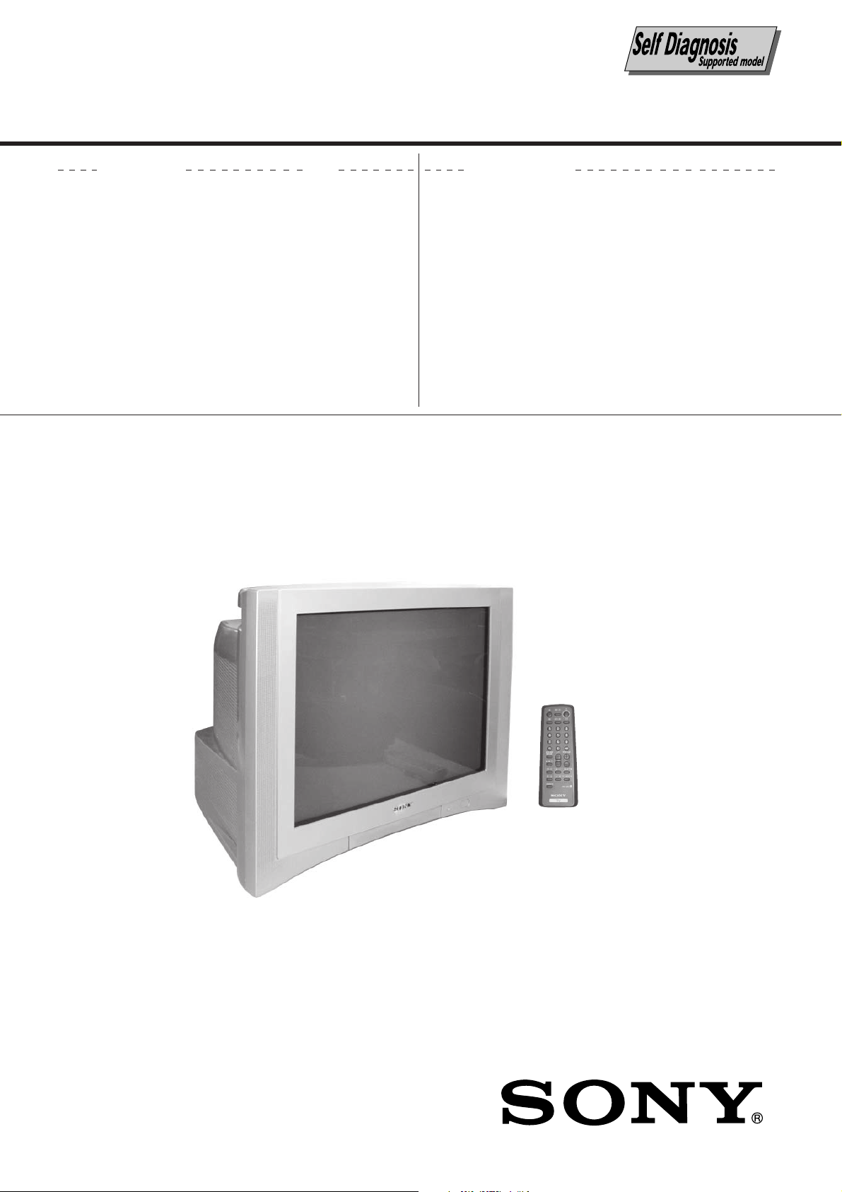
TRINITRON
®
COLOR TV
KV-AR25M81A
RM-952
Power requirements 110-240 V AC, 50/60 Hz
Power consumption (W) Indicated on the rear of the TV
Television system B/G, I, D/K, M
Color system PAL, PAL 60, SECAM, NTSC3.58, NTSC4.43
Teletext language English, Arabic, French
Channel coverage
B/G VHF: E2 to E12
I UHF: B21 to B68
D/K VHF: C1 to C12, R1 to R12
M VHF: A2 to A13
˘(Antenna) 75-ohm external terminal
Audio output (Speaker) 5W + 5W
Number of terminal
DVideo Input: 3* Output: 1 Phono jacks; 1 Vp-p, 75 ohms * Two input lines available
≥ Audio Input: 3* Output: 1 Phono jacks; 500 mVrms * Two input lines available
(S Video) Input : 1 Y: 1 Vp-p, 75 ohms,
(Component Input : 1 Phono jacks:
Video) Y: 1 Vp-p, 75 ohms,
2 (Headphone) Output: 1 Stereo minijack
Picture tube 25 in.
Tube size (cm) 64 Measured diagonally
Screen size (cm) 60 Measured diagonally
Dimension (w/h/d,mm) 650 × 517 × 496
Mass (kg) 39
SPECIFICATIONS
UHF: E21 to E69
CATV: S01 to S03, S1 to S41
CATV: S01 to S03, S1 to S41
UHF: C13 to C57, R21 to R60
CATV: S01 to S03, S1 to S41, Z1 to Z39
UHF: A14 to A79
CATV: A-8 to A-2, A to W+4, W+6 to W+84
unbalanced, sync negative
C: 0.286 Vp-p, 75 ohms
sync negative
CB: 0.7 Vp-p, 75 ohms
R: 0.7 Vp-p, 75 ohms
C
Audio: 500mVrms
Note
CAUTION
SHORT CIRCUIT THE ANODE OF THE PICTURE TUBE AND
THE ANODE CAP TO THE METAL CHASSIS, CRT SHIELD, OR
CARBON PAINTED ON THE CRT, AFTER REMOVING THE
ANODE.
Design and specifications are subject to change without notice.
SAFETY-RELATED COMPONENT WARNING!!
COMPONENTS IDENTIFIED BY SHADING AND MARK ! ON
THE SCHEMATIC DIAGRAMS, EXPLODED VIEWS AND IN THE
PARTS LIST ARE CRITICAL TO SAFE OPERATION. REPLACE
THESE COMPONENTS WITH SONY PARTS WHOSE PART
NUMBERS APPEAR AS SHOWN IN THIS MANUAL OR IN
SUPPLEMENTS PUBLISHED BY SONY.
– 2 –

TABLE OF CONTENTS
KV-AR25M81A
RM-952
Section Title Page
SELF DIAGNOSTIC FUNCTION ........................................4
1. DISASSEMBLY
1-1. Rear Cover Removal ................................................... 7
1-2. Speaker Block Assy Removal ..................................... 7
1-3. Chassis Assy Removal ................................................ 7
1-4. Service Position .......................................................... 7
1-5. Terminal Bracket and J Board Removal .................... 7
1-6. V1 Board Removal ..................................................... 7
1-7. H1 and H2 Boards Removal ....................................... 8
1-8. A and B9 Boards Removal ......................................... 8
1-9. Picture Tube Removal................................................. 8
2. SET-UP ADJUSTMENTS
2-1. Beam Landing ........................................................... 10
2-2. Convergence .............................................................. 11
2-3. Focus Adjustment ..................................................... 13
2-4. G2 (SCREEN) and White Balance Adjustment ....... 14
3. CIRCUIT ADJUSTMENTS
3-1. Adjustment With Commander .................................. 15
3-2. Adjustment Method .................................................. 15
3-3. Picture Quality Adjustments..................................... 21
3-4. Deflection Adjustments ............................................ 21
3-5. H-Trapezoid Adjustment .......................................... 22
3-6. A Board Adjustment After IC003 (MEMORY)
Replacement .............................................................. 22
3-7. Picture Distortion Adjustment .................................. 23
Section Title Page
4. DIAGRAMS
4-1. Block Diagram .......................................................... 24
4-2. Circuit Board Location ............................................. 26
4-3. Schematic Diagram ................................................... 27
(1) A Board Schematic Diagram .............................. 28
(2) B9 Board Schematic Diagram ............................ 32
(3) V1 Board Schematic Diagram ............................ 34
(4) C6 Board Schematic Diagram ............................ 36
(5) H1 Board Schematic Diagram ............................ 38
(6) H2 Board Schematic Diagram ............................ 40
(7) J Board Schematic Diagram ............................... 41
(8) VM1 Board Schematic Diagram ........................ 42
4-4. Voltage List and Waveforms ..................................... 43
4-5. Printed Wiring Boards and Parts Location ............... 47
4-6. Semiconductors ......................................................... 52
5. EXPLODED VIEWS
5-1. Speaker Block ........................................................... 54
5-2. Chassis ...................................................................... 55
5-3. Picture Tube .............................................................. 56
6. ELECTRICAL PARTS LIST ......................................... 57
INSTRUCTION MANUAL
– 3 –

KV-AR25M81A
RM-952
SELF DIAGNOSTIC FUNCTION
The units in this manual contain a self-diagnostic function. If an error occurs, the STANDBY/TIMER lamp will automatically
begin to flash.
The number of times the lamp flashes translates to a probable source of the problem. A definition of the STANDBY/TIMER
lamp flash indicators is listed in the instruction manual for the user’s knowledge and reference. If an error symptom cannot
be reproduced, the remote commander can be used to review the failure occurrence data stored in memory to reveal past
problems and how often these problems occur.
1. DIAGNOSTIC TEST INDICATORS
When an errors occurs, the STANDBY/TIMER lamp will flash a set number of times to indicate the possible cause of the
problem. If there is more than one error, the lamp will identify the first of the problem areas.
Result for all of the following diagnostic items are displayed on screen. No error has occured if the screen displays a “0”.
Diagnostic
Item
Description
• Power does not
turn on
• +B overcurrent
(OCP) or
overvoltage
(OVP)
• Vertical deflection
stopped
• Horizontal
deflection
overdrive
• White balance
failure (no
PICTURE)
No. of times
STANDBY/TIMER
lamp flashes
Does not light
2 times
5 times
Self-diagnostic
display/Diagnostic
result
—
002:000 or
002:001~255
003:001~255
004:001~255
at the same time
005:000 or
005:001~225
Probable
Cause
Location
• Power cord is not plugged
in.
• Fuse is burned out F4601
(F)
• H.OUT Q511 is shorted.
(A board)
• Q701, Q702, Q703 is
shorted (C6 board)
• -13V is not supplied.
(A board)
• IC 503 faulty (A board)
• G2 is improperly adjusted.
(Note 2)
• CRT problem.
• R(Q703), G(Q702) or
B(Q701) out is faulty
(C6 board)
• IC301 is faulty. (A board)
• No connection A board to
C6 board.
Detected
Symptoms
• Power does not come on.
• No power is supplied to the
TV.
• AC power supply is faulty.
• Power does not come on.
• Load on power line is
shorted.
• Has entered standby state
after horizontal raster.
• Vertical deflection pulse is
stopped.
• Power line is shorted or
power supply is stopped.
• No raster is generated.
• CRT cathode current
detection reference pulse
output is small.
• Micro reset
Note 1: If a + B overcurrent is detected, stoppage of the vertical deflection is detected simultaneously.
The symptom that is diagnosed first by the microcontroller is displayed on the screen.
Note 2: Refer to screen (G2) Adjustment in section 2-4 of this manual.
* R(Q703), G(Q702) or B(Q701) out is faulty (C6 board).
—
101:00 or
101:001~225
• Discharge CRT (C6 Board)
• Static discharge
• External noise
• Power is shut down shortly,
after this return back to
normal.
• Detect Micro latch up.
– 4 –
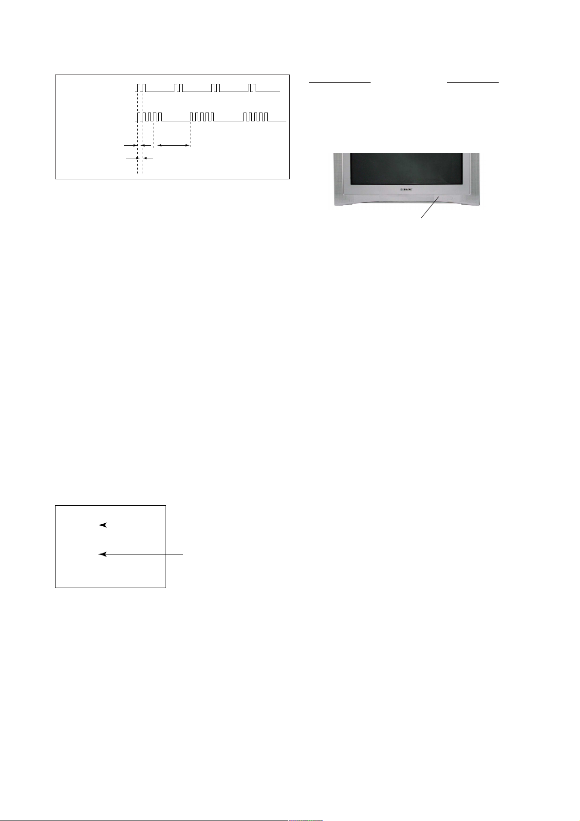
2. DISPLAY OF STANDBY/TIMER LIGHT FLASH COUNT
KV-AR25M81A
RM-952
2 times
+B overcurrent/overvoltage 2 times
Vertical deflection stopped
Diagnostic Item Flash Count*
5 times
Lamp ON 0.3 sec.
Lamp OFF 0.3 sec.
Lamp OFF 3 sec.
White balance failure 5 times
* One flash count is not used for self-diagnostic.
STANDBY/SLEEP lamp
3. STOPPING THE STANDBY/TIMER FLASH
Turn off the power switch on the TV main unit or unplug the power cord from the outlet to stop the STANDBY/TIMER lamp
from flashing.
4. SELF-DIAGNOSTIC SCREEN DIPLAY
For errors with symptoms such as “power sometimes shuts off” or “screen sometimes goes out” that cannot be confirmed, it
is possible to bring up past occurances of failure for confirmation on the screen:
[To Bring Up Screen Test]
In standby mode, press buttons on the remote commander sequentially in rapid succession as shown below:
[Screendisplay] / channel [5] / Sound volume [-] / Power ON
˘
Note that this differs from entering the service mode (mode volume [+]).
Self-Diagnosis screen display
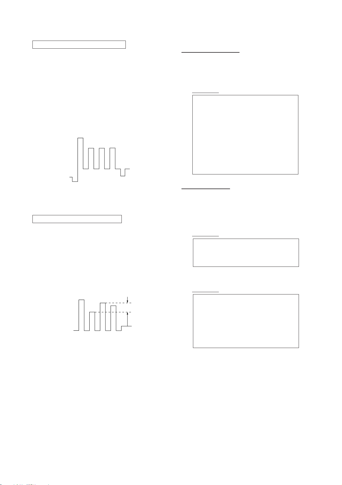
SELF DIAGNOSTIC
002 : 000
003 : 000
004 : 000
005 : 001
101 : 000
Numeral "0" means that no fault has been detected.
Numeral "1" means a fault has been detected.
– 5 –
KV-AR25M81A
RM-952
5. HANDLING OF SELF-DIAGNOSTIC SCREEN DISPLAY
Since the diagnostic results displayed on the screen are not automatically cleared, always check the self-diagnostic screen
during repairs. When you have completed the repairs, clear the result display to “0”.
Unless the result display is cleared to “0”, the self-diagnostic function will not be able to detect subsequent faults after
completion of the repairs.
[Clearing the result display]
To clear the result display to “0”, press buttons on the remote commander sequentially as shown below when the diagnostic
screen is being displayed.
Channel [8] / 0
[Quitting Self-diagnostic screen]
To quit the entire self-diagnostic screen, turn off the power switch on the remote commander or the main unit.
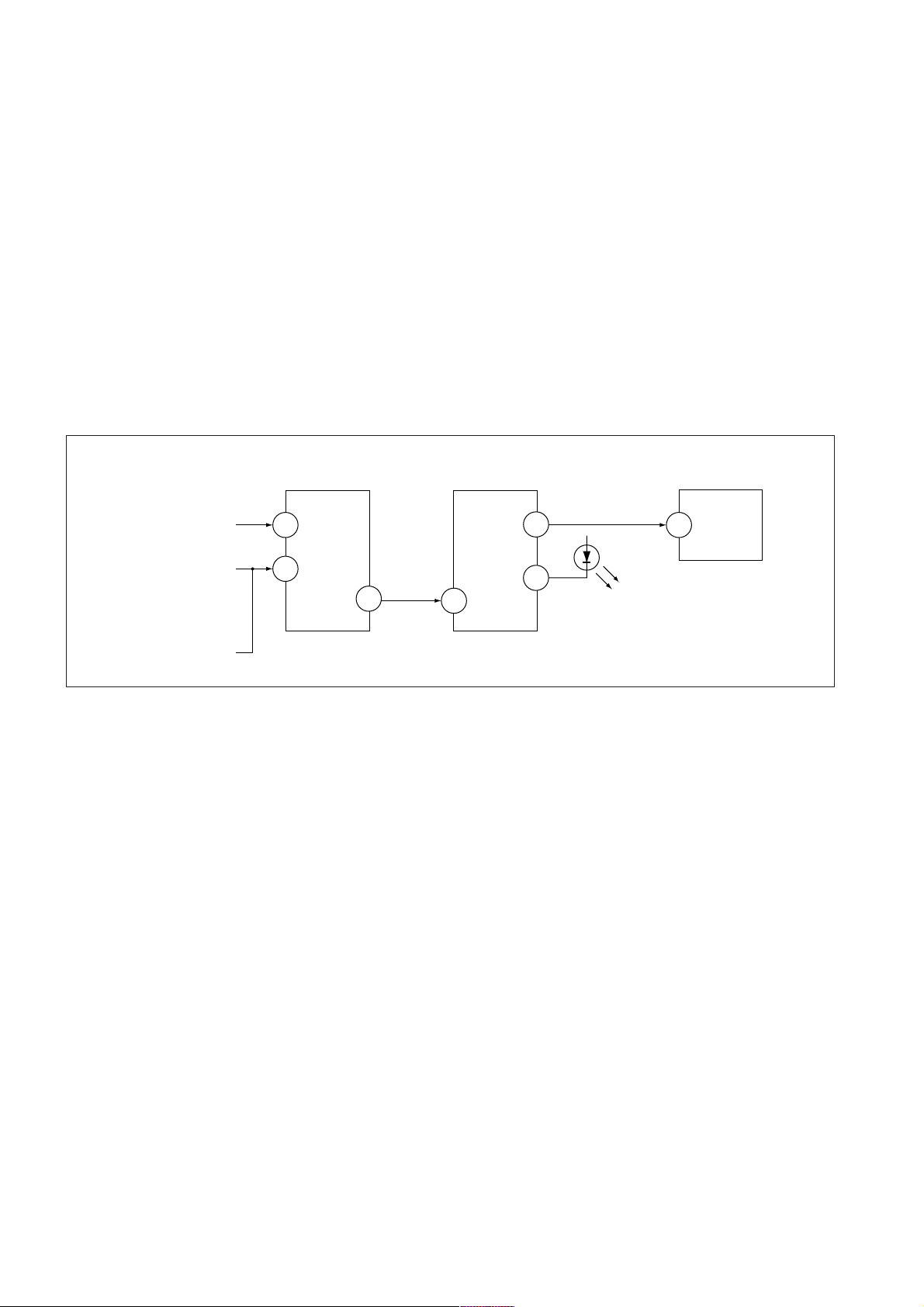
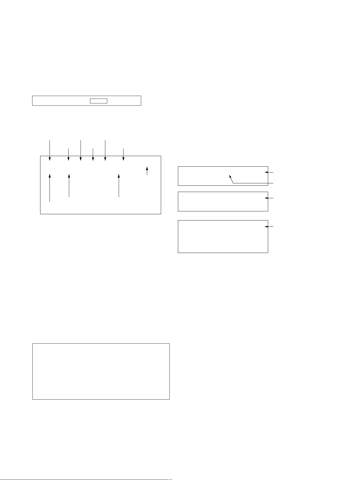
6. SELF-DIANOSTIC CIRCUIT
FROM
CRT
FROM
[+B] Q604 C6
[V] Q509/507
IC301
Y/CHROMA JUNGLE
IK-IN
MP/
18
PROTECT
35
SDA
IC001
SYSTEM
IO-8DAT B-DAT
O-LED
46
IO-SDAT
45
51
IC003
MEMORY
521
[+BovercurrentªOCPº] Occurs when an overcurrent on the +B(135) line is detected by Q604. If Q604 go to ON
and the voltage to pin 18 of IC301 should go down when V.SYNC is more than seven
verticals in a period, the unit will automatically turn off.
[Verticaldeflectionstopped] Occurs when an absence of the vertical deflection pulse is detected by Q509 and IC001
shut down the power supply.
[Verticaldeflectionovercurrent] Occurs when an overcurrent on V drive line is detected by Q507. Power supply will be
shut down when detect this by IC001.
[Whitebalancefailure] If the RGB levels* do not balance or become low level within 5 seconds, this error will be
detected by IC301. TV will stay on, but there will be no picture.
* (Refers to the RGB levels of the AKB detection Ref pulse that detects IK.)
– 6 –
SECTION 1
DISASSEMBLY
KV-AR25M81A
RM-952
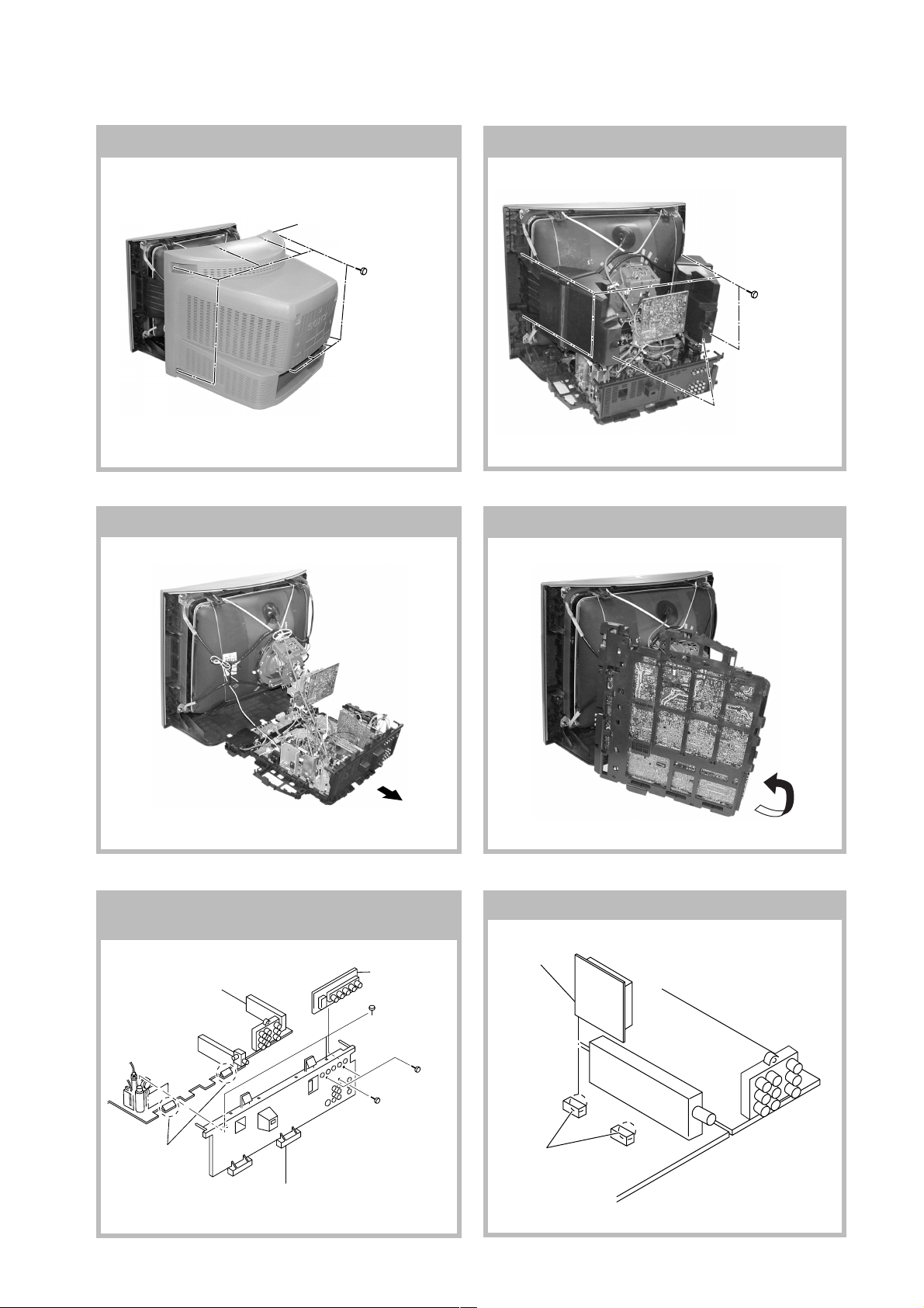
1-1. REAR COVER REMOVAL
2 Rear cover
1-3. CHASSIS ASSY REMOVAL
1 Nine screws
(+BVTP 4 × 16)
1-2. SPEAKER BLOCK ASSY REMOVAL
1 Four screws
(Washer head)
(+P 4×16 )
2 Speaker Block Assy
1-4. SERVICE POSITION
1-5. TERMINAL BRACKET AND J BOARD
REMOVAL
3 J Board
4 Two screw
(+BVTP 3 × 12)
2 Two screws
(+BVTP 3 × 12)
1 One screw
(+BVTP 4 × 16)
6 Two Hooks
5 Terminal bracket
1-6. V1 BOARD REMOVAL
2 V1 Board
1 Two claws
– 7 –
KV-AR25M81A
RM-952
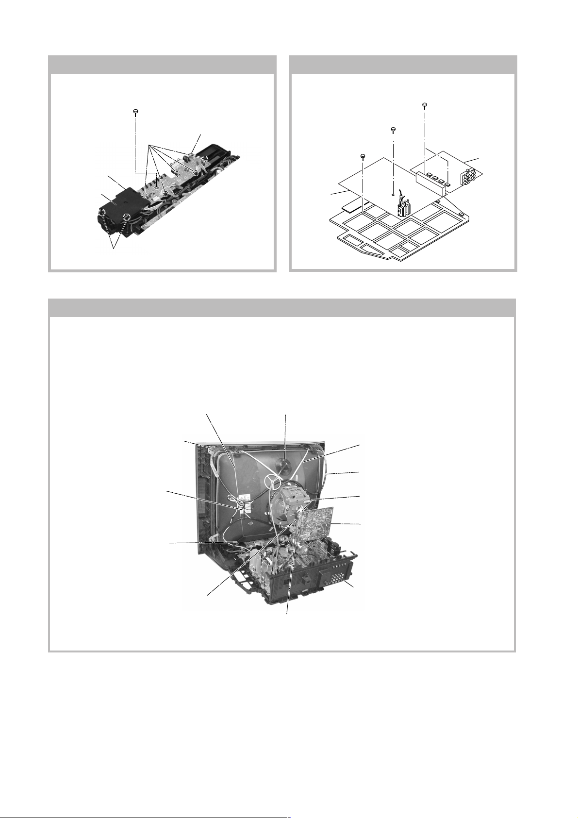
1-8. A AND B9 BOARDS REMOVAL1-7. H1 AND H2 BOARDS REMOVAL
3 Two screws
(Washer head)
(+BVTAP 3 x 12)
(Washer head)
(+BVTAP 3 x 12)
4 B9 Board
6 H2 Board
5 Cover, H
4 Two hooks
1 Two screws
(Washer head)
(+BVTP 3 x 12)
3 Four hooks
3 H1 Board
1 One screw
(Washer head)
(+BVTAP 3 x 12)
5 A Board
2 One screw
1-9. PICTURE TUBE REMOVAL
Note:
• Please make sure the TV set is not in standing position before removing necessary CRT support located on bottom
right and left.
1) Place the TV set with the CRT face down on a cushion jig.
2) Removal the rear cover.
3) Removal the Speaker Block Assy.
qf Earth Coating Assy
!∞ Nut, locking
!¡ Holder, DGC(2)
Removal
q; Spring Tension(2)
Removal
8 Loosen the Neck Assembly
fixing screw and removal
4 Anode Cap Removal
!£ Band, DGC Removal
qs Degaussing Coil
6 Loosen the Neck Assembly
fixing screw and removal
5 C6 Board Removal
9 Chassis Assy Removal
7 VM1 Board Removal
– 8 –
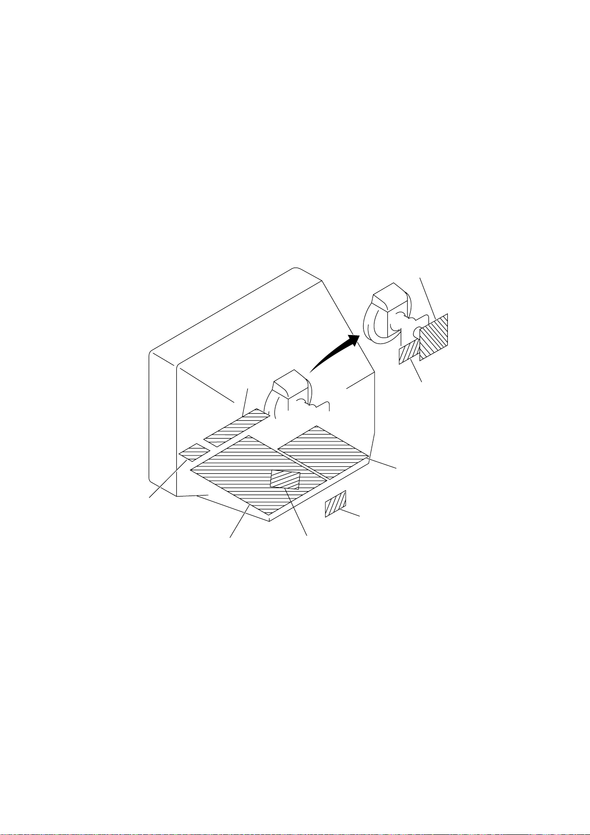
KV-AR25M81A
c
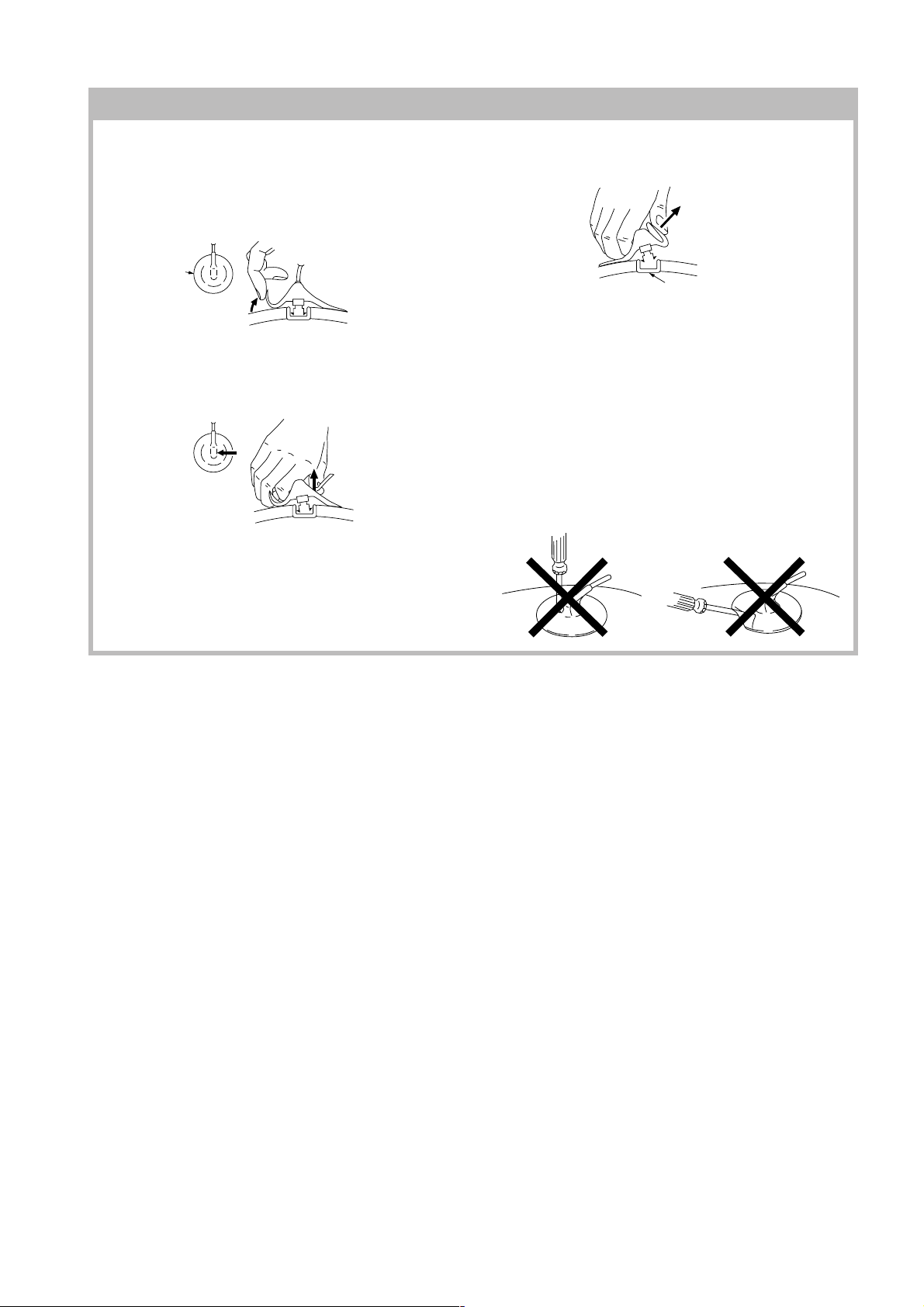
• REMOVAL OF ANODE-CAP
Note:
• After removing the anode, short circuit the anode of the picture tube and the anode cap to the metal chassis, CRT
shield or carbon paint on the CRT.
• REMOVING PROCEDURES
a
a
1 Turn up one side of the rubber cap in the direction
indicated by the arrow a.
b
b
2 Using a thumb pull up the rubber cap firmly in the direc-
tion indicated by the arrow b.
3 When one side of the rubber cap is separated from the
anode button, the anode-cap can be removed by
turning up the rubber cap and pulling it up in the
direction of the arrow c.
• HOW TO HANDLE AN ANODE-CAP
1 Do not damage the surface of anode-caps with
sharp shaped objects.
2 Do not press the rubber too hard so as not to
damage the inside of anode-cap.
A metal fitting called the shatter-hook terminal is
built into the rubber.
3 Do not turn the foot of rubber over too hard.
The shatter-hook terminal will stick out or damage
the rubber.
anode button
RM-952
– 9 –
KV-AR25M81A
RM-952
SECTION 2
SET-UP ADJUSTMENTS
• The following adjustments should be made when a complete
realignment is required or a new picture tube is installed.
• These adjustments should be performed with rated power
supply voltage unless otherwise noted.
Perform the adjustments in the following order :
1. Beam Landing
2. Convergence
3. Focus
4. White Balance
Controls and switches should be set as follows unless otherwise noted:
PICTURE control ........................................................... normal
BRIGHTNESS control ................................................... normal
Note : Test Equipment Required.
1. Pattern Generator
2. Degausser
3. Oscilloscope
○○○○○○○○○○○○○○○○○○○○○○○○○○○○○○○○○○○○○○○○○○○○○○○○○○○○○○○○○○○○○○○
Preparation :
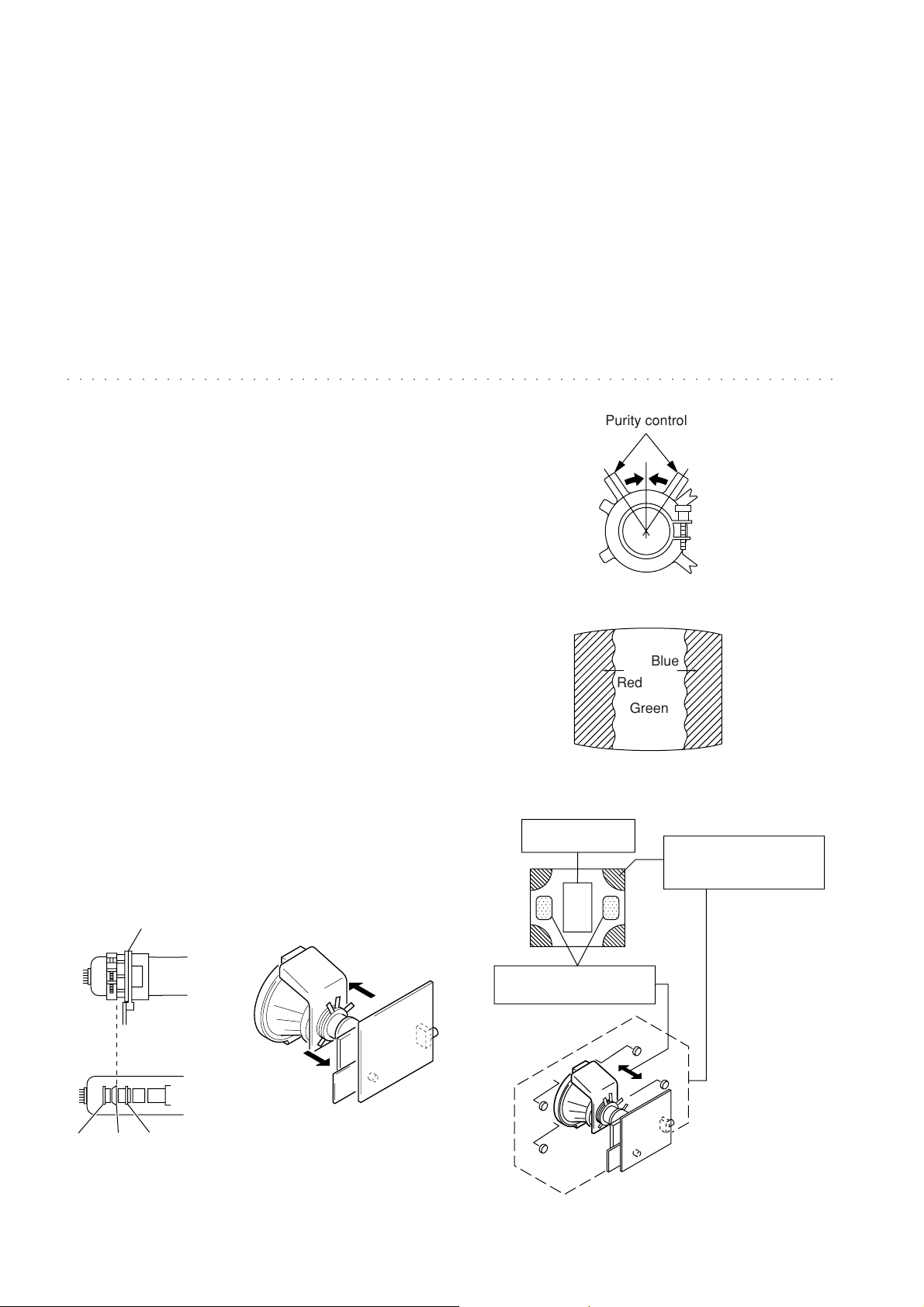
• In order to reduce the influence of geomagnetism on the set's
Purity control
picture tube, face it east or west.
• Switch on the set's power and degauss with the degausser.
2-1. BEAM LANDING
1. Input a white signal with the pattern generator.
Contrast
Brightness
2. Position neck assy as shown in Fig2-2.
}
normal
Fig. 2-3
3. Set the pattern generator raster signal to a green raster.
4. Move the deflection yoke to the rear and adjust with the
purity control so that the green is at the center and the blue
and the red take up equally sized areas on each side.
(See Figures 2-1 through 2-4.)
5. Move the deflection yoke forward and adjust so that the
Blue
Red
Green
entire screen is green. (See Figure 2-2.)
6. Switch the raster signal to blue, then to red and verify the
condition.
7. When the position of the deflection yoke has been decided,
Fig. 2-4
fasten the deflection yoke with the screws and DY spacers.
8. If the beam does not land correctly in all the corners, use a
magnet to adjust it.
(See Figure 2-5.)
Purity control
corrects this area.
b
a
Disk magnets or rotatable
disk magnets correct these
areas (a-d).
Neck assy
Align the edge of
the neck assy with
the edge of the G2 grid.
G2G1 G3
Fig. 2-1
Fig. 2-2
– 10 –
c
Deflection yoke positioning
corrects these areas.
a
d
d
Fig. 2-5
b
c
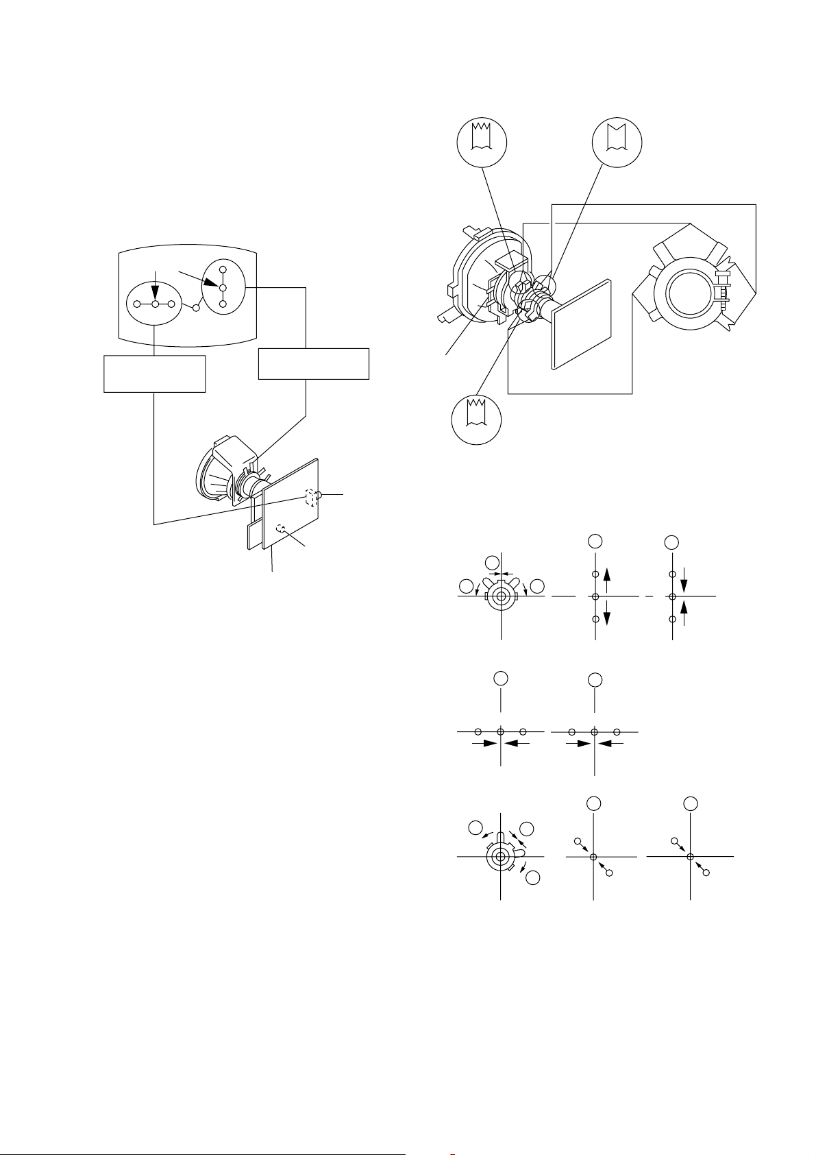
2-2. CONVERGENCE
Purity
BMC
BMC (Hexapole)
Purity
DY pocket
V.STAT
V.STAT
Preparation :
• Before starting this adjustment, adjust the focus, horizontal size
and vertical size.
• Receive dot/hatch signal.
• Pic mode: Personal (Pic 90%, Brightness 50%, Colour 50 %,
Hue 50%, Sharpness 50%).
(1) Horizontal and Vertical Static Convergence
KV-AR25M81A
RM-952
Center dot
RGB
H. STAT VR
R
G
B
V. STST
Magnet
RV702
H. STAT
RV701
SCREEN (G2)
C6 Board
1. (Moving horizontally), adjust the H.STAT control so that the
red, green and blue dots are on top of each other at the center of
the screen.
2. (Moving vertically), adjust the V.STAT magnet so that the red,
green and blue dots are on top of each other at the center of the
screen.
3. If the H.STAT variable resistor cannot bring the red, green and
blue dots together at the center of the screen, adjust the
horizontal convergence with the H.STAT variable resistor and
the V.STAT magnet in the manner given below.
(In this case, the H.STAT variable resistor and the V.STAT
magnet influence each other, so be sure to perform adjustments
while tracking.)
1 V. S TAT
a
b b
2 H. STAT VR
a
RGGBB
3
a
B
G
R
b
R
a
b
B
G
R
b
– 11 –
b
a
R
b
G
B
B
G
R
KV-AR25M81A
RM-952
4 BMC (Hexapole) Magnet.
If the red, green and blue dots are not balanced or aligned, then
use the BMC magnet to adjust in the manner described below.
RG B R G B R GB
RB
G
RG
GB
RB
5 Y separation axis correction magnet adjustment.
1. Receive the cross-hatch signal and adjust [PICTURE] to [MIN]
and [BRIGHTNESS] to [STANDARD] .
Neck assy Neck assy
Blue
Red Blue
VM1 board VM1 board
Note
1. The Red and Blue magnets should be equally far from the
horizontal center line.
2. Do not separate the Red and Blue magnets too far.
(Less than 8 mm)
Red
2. Adjust the Y separation axis correction magnet on the neck
assembly so that the horizontal lines at the top and bottom of
the screen are straight.
(2) Dynamic Convergence Adjustment
Preparation:
• Before starting this adjustment, adjust the horizontal static
convergence and the vertical static convergence
RB
TLH TLV
B
R
RB
R
B
YCH XCV
– 12 –

KV-AR25M81A
RM-952
TLV Rotate TLV-2 VOL (29”, 34”) on DY
Rotate TLV VOL (25”)
XCV Rotate XCV Adj core on DY
YCH Rotate YCH VOL on DY
TLH Insert TLH Correction Plate to DY Pocket
(Left or Right)
ON DY:
YCH
TLV1
XCV
TLV2
(3) Screen-corner Convergence
ba
a-d : screen-corner
misconvergence
2-3. FOCUS ADJUSTMENT
FOCUS adjustment should be completed before W/B adjustment.
Focus
Screen
FLYBACK TRANSFORMER (T503)
1. Receive digital monoscope pattern.
2. Set "Picture Mode" to "DYNAMIC".
3. Adjust focus VR so that the lion teeth becomes just focus.
4. Change the receiving signal to white pattern blue back.
5. Confirm Magenta ring is not noticable. Incase magneta ring is
obvious, adjust FOCUS VR to take balance of MAGENTA
RING and FOCUS.
cd
Fix a Permalloy assy corresponding to the misconverged
areas.
a
d
Permalloy assembly
b
c
– 13 –
KV-AR25M81A
RM-952
2-4. G2 (SCREEN) AND WHITE BALANCE
ADJUSTMENTS
1. G2 (SCREEN) ADJUSTMENT
1) Set the PICTURE to normal.
2) Put to VIDEO input mode without signals.
3) Connect R, G and B of the C6 board cathode to the
oscilloscope.
4) Adjust BRIGHTNESS to obtain the cathode voltage to the
value below.
5) Adjust G2 (screen) on the FBT until picture shows the point
before cut off.
Cathode setting voltage:
180 V ± 2 (VDC)
0 V
2. WHITE BALANCE ADJUSTMENT
1) Set to Service Mode (Refer Section 3-1: ADJUSTMENTS
WITH COMMANDER).
2) Input white raster signal.
3) Set the PICTURE to minimum.
4) Select WHB 04 "GCT" and WHB 05 "BCT" with [1] and
[4], and adjust the level with [3] and [6] for the best
white balance.
5) Set the PICTURE to maximum.
6) Select WHB 01 "GDR" and WHB 02 "BDR" with [1] and [4],
and adjust the level with [3] and [6] for the best white
balance.
7) Write into the memory by pressing [MUTING] then [0].
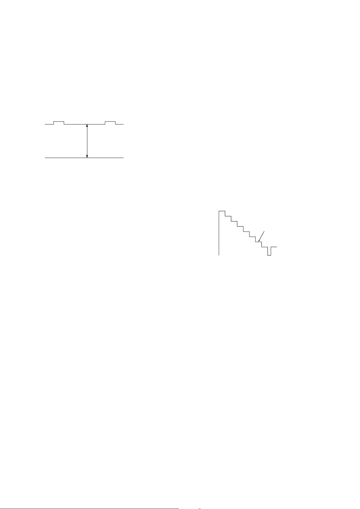
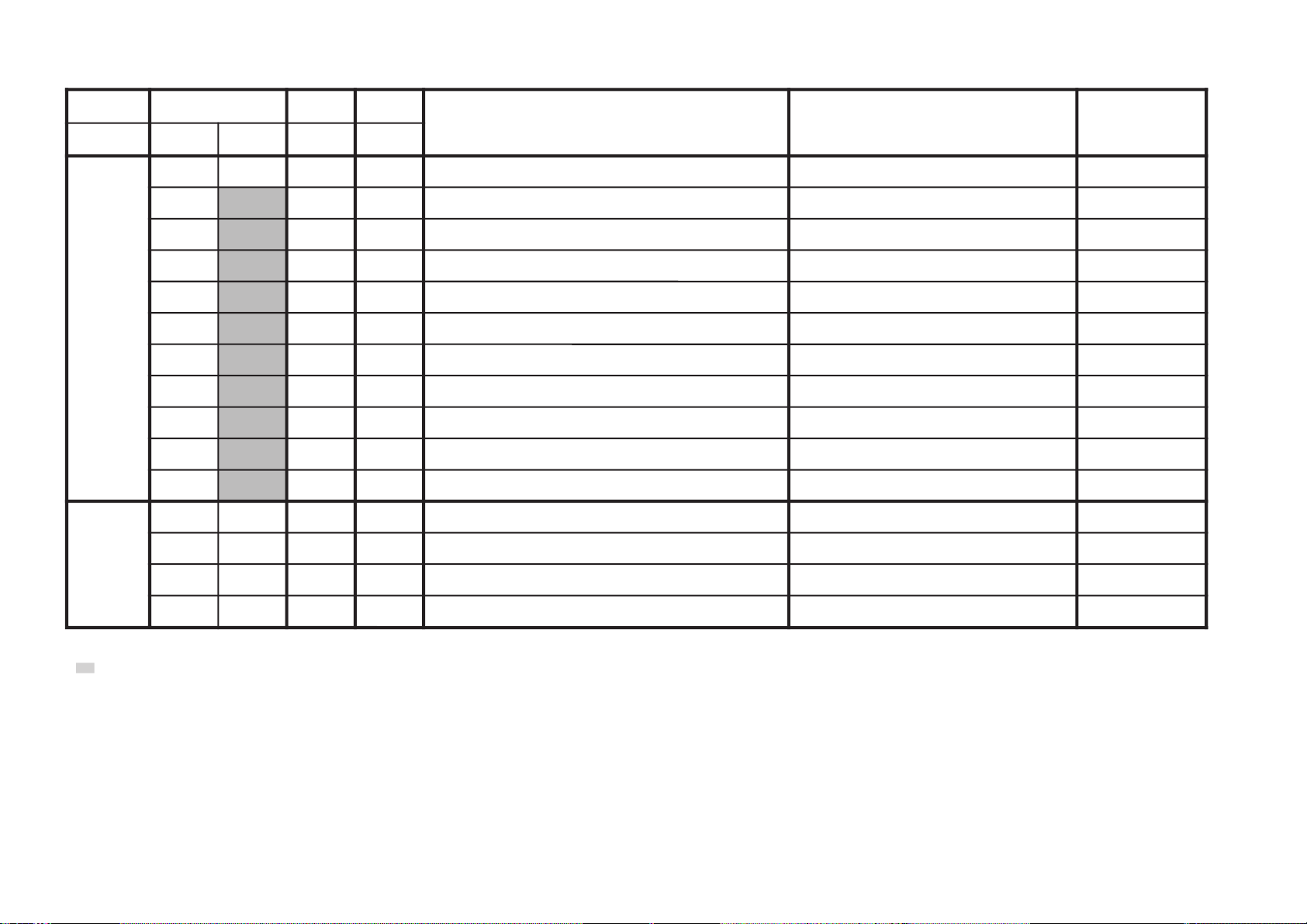
3. SUB BRIGHT ADJUSTMENT
1) Set to service mode.
2) Input a staircase signal of black to white from the pattern
generator.
3) BRIGHTNESS ....50%.
PICTURE ............MINIMUM
4) Select WHB 07 "SBR" with [1] and [4], and adjust WHB 07
"SBR" level with [3] and [6] so that the second stripe from the
right is dimly lit.
White
second from the right
Black
– 14 –
SECTION 3
1F 50HPS SERVICE
GEO 00
7F 0 000A59
0.3A
1F WRITE 50HPS
GEO 00
7F 0 000A59
0.3A
1F 50HPS WRITE
GEO 00
7F 0 000A59
0.3A
GREEN
Write with [MUTING]
Write executed with -
GREEN
RED
The WRITE display
then the display
returns to green
SERVICE.
Adjusted with 3
and 6 buttons.
638S
638S
638S
CIRCUIT ADJUSTMENTS
KV-AR25M81A
RM-952
3-1. ADJUSTMENTS WITH COMMANDER
Service adjustments to this model can be performed using the
supplied Remote Commander RM-952.
a. ENTERING SERVICE MODE
With the unit on standby
n
[DISPLAY] n 5 n VOL (+) n [POWER]
This operation sequence puts the unit into service mode.
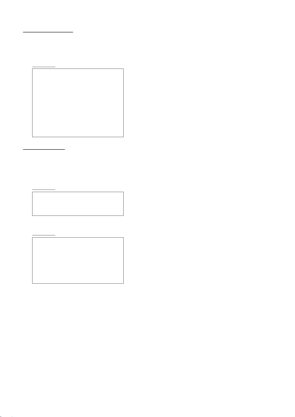
The screen display is :
Device
Name
Software version Total Power-On time (hours)
Suffix No
(OEM Code)
b. METHOD OF CANCELLATION FROM SERVICE
MODE
Set the standby condition (Press [POWER] button on the commander),
then press [POWER] button again, hereupon it becomes TV mode.
Item No
00
0.3A
Item
Name
Data Mode
HPS SERVICE 501C pGEO
59 7F 000A0638S
Marking of new NVM
PAL,SECAM:50
NTSC :60
3-2. ADJUSTMENT METHOD
Item Number 00 of device GEO
This explanation uses H-Position as an example.
1. Select “GEO 00 HPS” with the 1 and 4 buttons.
2. Raise/lower the data with the 3 and 6 buttons.
3. Select the optimum state. (The standard is 1F for PAL
reception.)
4. Write with the [MUTING] button. (The display changes to
WRITE.)
5. Execute the writing with the - button. (The WRITE
display will be changed to red color while excuting, and
back to SERVICE.)
Example on screen display :-
c. METHOD OF WRITE INTO MEMORY
1) Set to Service Mode.
2) Press [1] (UP) and [4] (DOWN), to select the adjustment.
4) Press [MUTING] button to indicate WRITE on the screen.
5) Press [0] button to write into memory.
d. MEMORY WRITE CONFIRMATION METHOD
1) After adjustment, pull out the plug from AC outlet, and then
2) Turn the power switch ON and set to Service Mode.
3) Call the adjusted items again to confirm adjustments were made.
[MUTING], - Write 50Hz adjustment data to 60Hz, or vice
plug into AC outlet again.
1, 4 Select the adjustment item.
↓
3, 6 Raise/lower the data value.
↓
[MUTING] Writes.
↓
- Executes the writing.
7, - All the data becomes the values in memory.
8, - All user control goes to the standard state.
5, - Service data initialization (Be sure not to use
usually.)
2, - Copy and write all data.
versa.
– 15 –
Use the same method for all Items. Use 1 and 4 to select the
adjustment item, use 3 and 6 to adjust, write with [MUTING],
then execute the write with -.
Note : 1. In [WRITE], the data for all items are written into
memory together.
2. For adjustment items that have different standard data
between 50Hz or 60Hz, be sure to use the respective
input signal after adjustment.
KV-AR25M81A
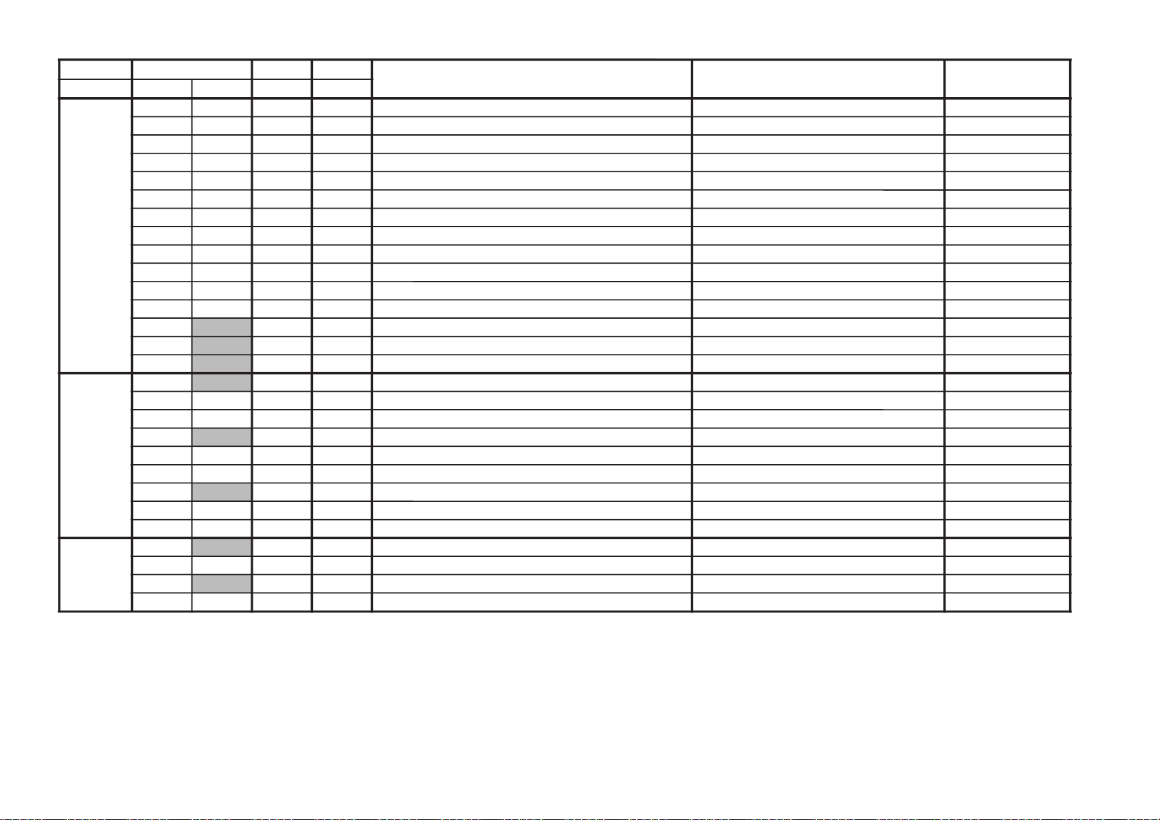
GVTytilanoitcnuF.tinIegnaR
noitcnuFetoN&elbaTeulaVlaitinI
)deliated(
yrogetaCoNemaN
OEG00SPH7F3noitisoPH )06/05(ediW/)06/05(lamroN)61/E1()61/E1(
10ZSHF1F3eziSH )06/05(ediW/)06/05(lamroNF1
20PAPF1F3pmAniP )06/05(ediW/)06/05(lamroNF1
30TLT7F0muizeparT )06/05(ediW/)06/05(lamroN70
40SPVF1F3noitisoPV )06/05(ediW/)06/05(lamroNF1
50ZSVF1F3eziSV )06/05(ediW/)06/05(lamroNF1
60OCS7F0noitcerroCS )06/05(ediW/)06/05(lamroN70
70NLV7F0ytiraeniLV )06/05(ediW/)06/05(lamroN70
80WOB7F0woBCFA )06/05(ediW/)06/05(lamroN70
90LGA7F0elgnACFA )06/05(ediW/)06/05(lamroN70
A0NPUF1F3niPreppU )06/05(ediW/)06/05(lamroNF1
B0NPLF1F3niPrewoL )06/05(ediW/)06/05(lamroNF1
C0
LBH01 ffo/nogniknalBH 10
D0
LBL2F0gniknalBHtfeL )06/05(ediW/)06/05(lamroN)F0/F0(/)F0/F0(
E0
LBRB0F0gniknalBHthgiR )06/05(ediW/)06/05(lamroN)00/00(/)00/00(
BHW00
RDR52F3evirDR srehto/CIMANYDA2/52
10RDG52F3evirDG srehto/CIMANYDF1
20RDB52F3evirDB srehto/CIMANYDF1
30
TCRA0F0ffotuCR srehto/MACES70
40TCG7F0ffotuCG srehto/MACES70
50TCB7F0ffotuCB srehto/MACES70
60
NMB51F1ataDmuminiMssenthgirB 51
70RBSF1F3lortnoCssenthgirBbuS 52
80BPA23 3#CNProfWSltCthgirBbuS 20
JAS00
XMP33F3ataDmumixaMerutciP ediW/ediW-noNE2/33
10UHS8F0lortnoCeuHbuS oediV-VT80
20
HSS3F0lortnoCssenprahSbuS oediV-VT90/50
30LCSF1F3lortnoCroloCbuS )srehto/CSTN(ediW/)srehto/CSTN(F1
RM-952
– 16 –
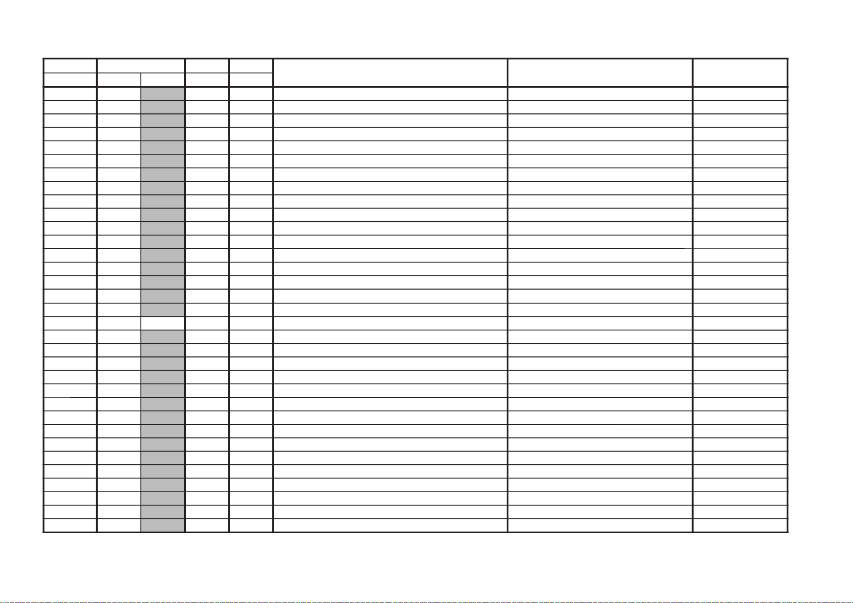
GVTytilanoitcnuF.tinIegnaR
noitcnuFetoN&elbaTeulaVlaitinI
)deliated(
yrogetaCoNemaN
PV00
THE4F0pmoCTHEzH06/05)20/20(/)20/20(
10
AMG230noitcerroCammaG 4ApaMMVNrefeR)10/10(/)20/20(
20
GPA01 3#CNProfWSltCammaG 00
30 LDY6F0yaleDY DVD/CSTN/MACES/LAP80/80/90/60
40
TSS130noitisoPtratSDIMACES LAP/MACES10/10
50
PSS130noitisoPpotSDIMACES LAP/MACES10/10
60
MLR03 timiLBGR 20
70
VLS230leveLDIMACES LAP/MACES20/20
80
FBS22F30fLLEBMACES LAP/MACES22/22
90
CYD11 ffo/noroloCcimanyD 10
A0
LBA11 gnihctiwSedoMLBA 0syawlADRADNATS10
B0
HTV11 gnihctiwShtVnoitceteDLBA 10
C0
0FS11 ssenprahSrofgnihctiwS0F srehto/CSTN10/10
D0
XCD11 gnihctiwSoitaRsnarTCD 10
E0
THS11 hctiwSoitartoohsrevO/-erP srehto/CSTN10/10
F0
WDH01 hctiwShtdiWesluPevirDH 00
01
CFA130lortnoCniaGCFA txeT/oediV/VT10/00/10
11SOH7F0noitallicsOH 70
21
SSH01 .peScnySHfoleveLecilS 00
31
SSV01 .peScnySVfoleveLecilS 00
41
SMH11 no/ffom/CnoisiVorcaMzH06/05)10/10(/)10/10(
51
VUY01 lortnoChctiwSVUY 10
61
VDC13 oediVrofedomDC ylnooediV10
71
NOR11NOR deziromemton10
81
NOG11NOG deziromemton10
91
NOB11NOB deziromemton10
A1
NOP11NOP deziromemton10
B1
NXA11 WSSIXA )anyDylnO(srehto/CSTN)10/10(/)10/10(
C1
LSR01 LESBGR 00
D1
WBV13 WKLBV 00
E1
PFR01PFER 00
F1
PMJ01pmuJ 00
02
CMV23 ffOMV 30
– 17 –
KV-AR25M81A
RM-952
KV-AR25M81A
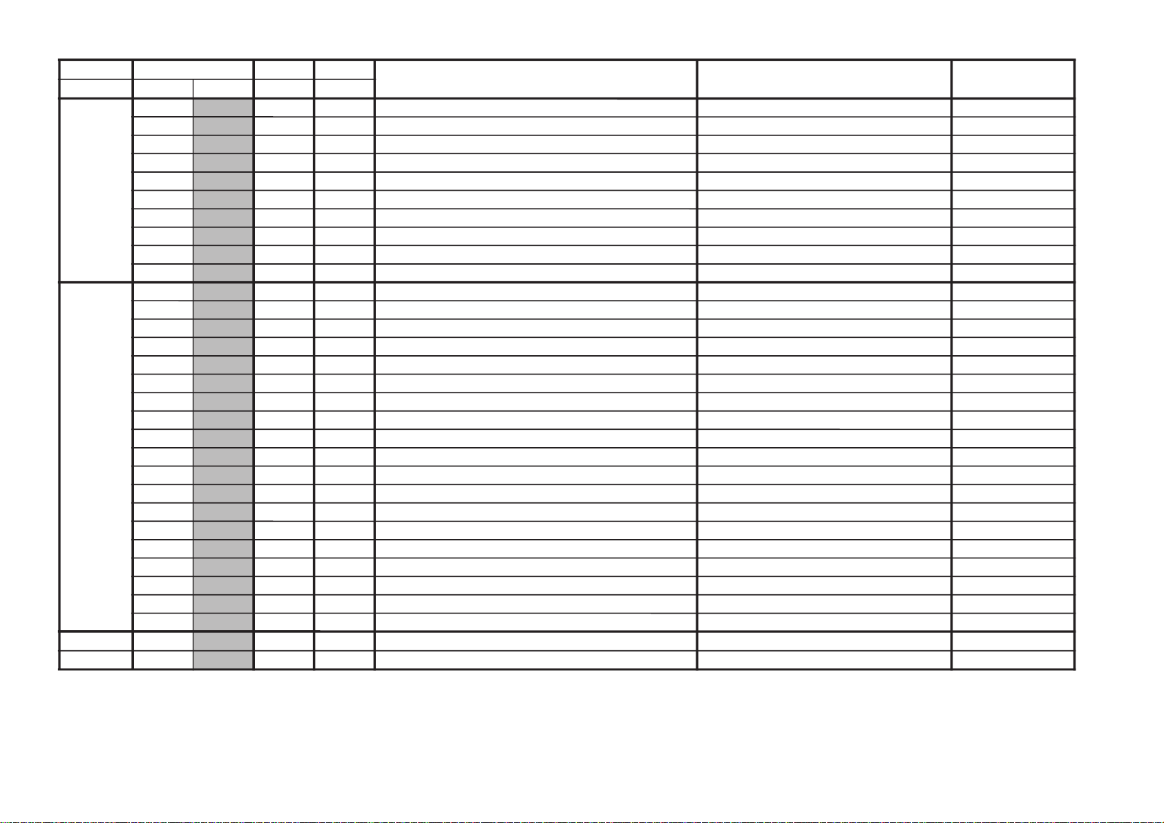
GVTytilanoitcnuF.tinIegnaR
noitcnuFetoN&elbaTeulaVlaitinI
)deliated(
yrogetaCoNemaN
PA00
FNI5F3ffodnuorrusnehWnoitaunettAtupnI 50
10
SNIA0F3)YLNO-GX(nodnuorrusnehWnoitaunettAtupnI A0
20
FES0F0)YLNO-AX(lortnoCtceffEdnuorruS 00
30
1HP33 noitceleSretsiger1esahP 30
40
2HP03 )YLNO-GX(noitceleSretsigeR2esahP 00
50
3HP03 )YLNO-GX(noitceleSretsigeR3esahP 00
60
4HP03 )YLNO-GX(noitceleSretsigeR4esahP 00
70
SCB23 tfihSretneCssaB 10
80
SCT23 tfihSretneCelberT 20
90
FRT23 tesffOelberTFR 20
PSM00
TSW51FFdlohserhToeretSG/W 51
10
TBWAEFFdlohserhTlaugniliBG/W CE
20
LLW5FFdlohserhTlaruanoMG/W 50
30
CAW0F0tnuoCtnemeergAG/W 10
40
LDW03FFyaleDhcraeSG/W 03
50
LDN02FFyaleDhcraeSMACIN 02
60
LDS01FFyaleDdaeRsutatsoeretS 01
70
CGA11 tnatsnoC/otuAhctiwSCGA 10
80
LER82F3edoMtnatsnoCtAniaGCGA 82
90
MRC01 ffo/nognitumreirraC 00
A0
OCA11 ffo/notuokcolCoiduA 10
B0
PFB1F7metsysM-nonrofelacserPMF B1
C0
MPF23F7metsysMrofelacserPMF 23
D0
HF63F7VEDHrofelacserPMF 63
E0
MHF56F7MdnaVEDHrofelacserPMF 56
F0
PGWA2F7elacserPG/W C1
01
PIND6F7elacserPMACIN F7
11
RRE05FFdlohserhThctiwsMFotuA 05
21
LOVD6FFh0ff7oth0007niaGrekaepS D6
TXT00
HXT03 noitisoPlatnoziroHtxeteleT 00
10
VXT03 noitisoPlacitreVtxeteleT 00
RM-952
– 18 –
GVTytilanoitcnuF.tinIegnaR
noitcnuFetoN&elbaTeulaVlaitinI
)deliated(
yrogetaCoNemaN
MPO00HSOA0F3noitisoPHDSO csiM-noitpOF0
10
MOC130noitceleSbmoC 20
20
CPA11 hctiwSCPA 10
30
YST030sySVTotuAtasySVT 00
40
TUM01 etuMlangiSoN 00
50
MFA01 hctiwSMFotuA 10
60
BFR03 lortnoCFPB-C 00
70
OVT07 tesffoelgnA-VottliT 20
80
LBD01 noitcnuFkcabeulBelbasiD 00
90
HCS1F7noitidnoCgnippihSrofnoitceleSHC ylnosledoMCSTN00
A0
ACS11 noitidnocgnippihsrofnoitcelesriA/elbaC ylnosledoMCSTN00
PSM001POFFFF)wolebees(1stiBlanoitpO stiB-noitpOFE
102PO26FF)wolebees(2stiBlanoitpO 66
203PO1BFF)wolebees(3stiBlanoitpO 1B
304PO20FF)wolebees(4stiBlanoitpO 20
– 19 –
NOTE
•
• Standard data listed on the Adjustment Item Table are reference values, therefore it may be different for each model and for each mode.
• Note for Different Data Those are the standard data values written on the microprocessor. Therefore, the data values of the modes and stored respectively in the memory.
shaded items are fixed data.
In case of a device replacement, adjustment by rewriting the data value is necessary for some items.
KV-AR25M81A
RM-952
KV-AR25M81A
RM-952
ITEM INFORMATION
No. OPB0 OP1
Item
KV-AR25M81A
NOTE: When Bit 7, 6 & 5 = 000, Only PAL color system is selected.
No. OPB1 OP2
Item
KV-AR25M81A 01
XTAL 4.43
1
XTAL 3.58
1
SECAM
1
2nd Lang
1
B/G
1
I
1
D/K
1
M
1
When Bit 7 is selected, Auto, PAL & NTSC 4.43 Color system is enable
When Option is single color system, Color system cannot be changed & “AUTO” will not be displayed.
TOP
0
NICAM
0
HDEV
0
Thai Bil.
0
Dis Fav.
0
DVD Input
1
AV Input
AV Input 00 = no AV Input 01 = 1 AV Input
10 / 11 = 2 AV Input
DVD Input Effective only when “AV Input” is set to 2 AV Input
Dis Fav. Disable Favorite Channel (Only Effective For 21” & 14” Models Only)
No. OPB2 OP3
Item
KV-AR25M81A
Pic Rot
2199 Curve
Pic Rot
1
*1
*1
2199 Curve
*1
0
Auto PIC Auto Picture Improvement 0 = inactive, 1 = active
A-TVsys Auto TV System in Auto Program0 = disabled, 1 = enabled
US ST USA Stereo 0 = disabled, 1 = enabled
AV Mono
*1
11 Key Front Key Selection 0 = 7 key model, 1 = 11 key model
Color SW
*2&*1
Note:*1 - For XA21/XG25 Models Only
*2
- For XA34/29/25 Models Only
No. OPB3 *OP4
Item
KV-AR25M81A
(unused)
0
(unused)0(unused)0(unused)0(unused)
*
*1
Auto PIC
1
A-TVsys
0
US ST
0
AV Mono
0
*1
11 Key
0
Colour SW
2&*1
1
Picture Rotation Feature Switch 0 = disabled, 1 = enabled
2199 Volume Curve Selection 0 = Others, 1= 2199 Volume Curve.
AV Mono models, 0 = Stereo, 1 = Mono (No Balance & Surround selection).
Color Data Selection in Dynamic Mode 0 = 65 (No PIP), 1 = 57 (PIP)
Vid NTSC3.58
0
0
AP_XG
*1
(unused)
1
0
AP_XG
*1
Note:*1 - For XA-21 / XG25 Models Only
To select the XG AP (board B6) ) 0: No; 1 = Yes
– 20 –
KV-AR25M81A
RM-952
3-3. PICTURE QUALITY ADJUSTMENTS
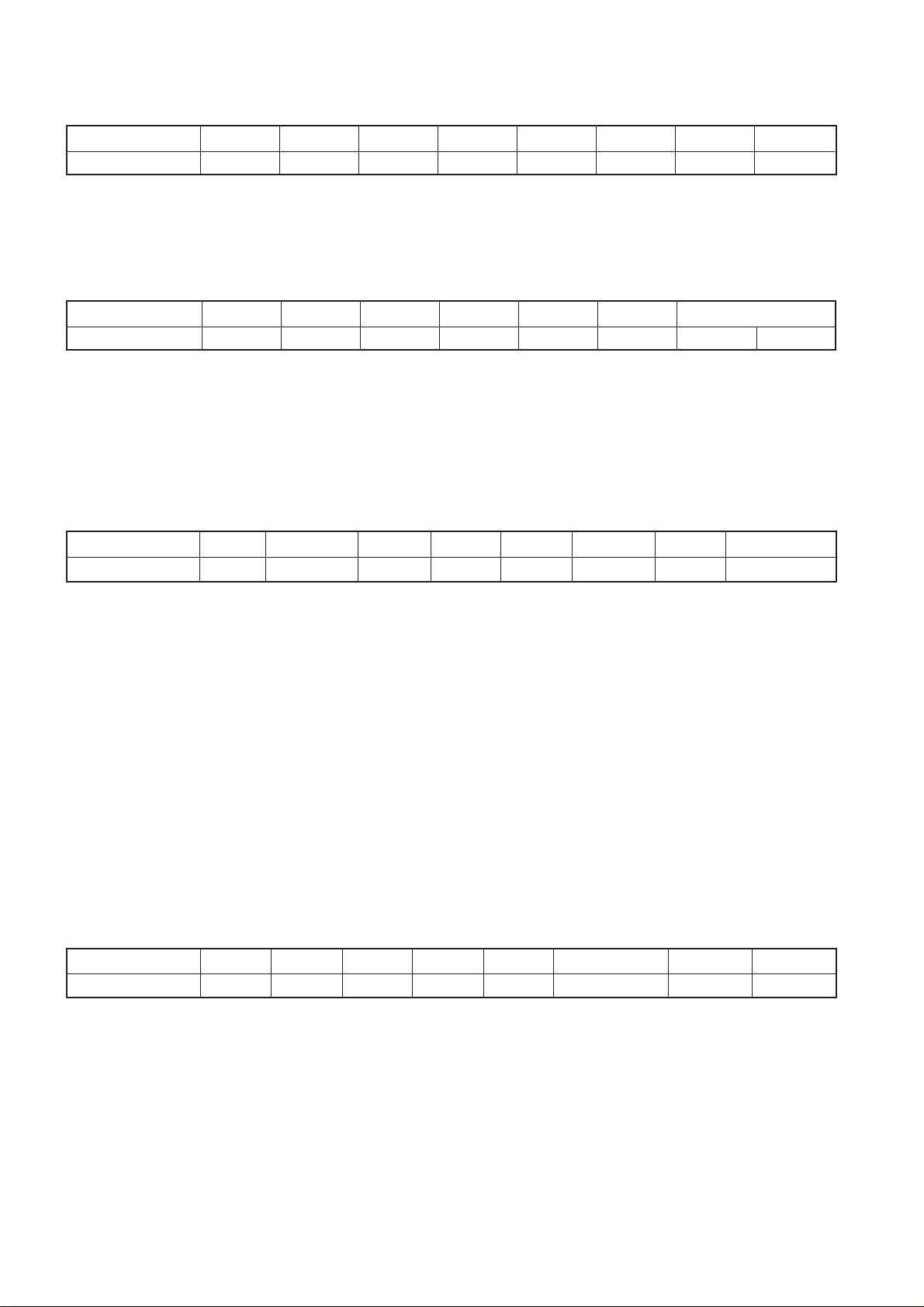
SUB COLOR ADJUSTMENT SCL
1. Select Video.
2. Input PAL Color Bar.
3. Set to following condition PICTURE 100%, BRIGHTNESS
50%, Color 50%.
4. Connect an oscilloscope to pin 1 (BOUT) of CN305, A Board.
5. Set the service mode and select SAJ 3 ‘SCL’ with 1 and 4 of
the commander then adjust the VB2=VB3=VB4 3 and 6.
6. Add 6 steps and save the data.
7. Input NTSC Color Bar.
8. Repeat item 4 to 6.
9. Select "WIDE" mode, write the "SAME DATA- 3 STEPS" for
both PAL and NTSC Color Bar input.
VB1
VB2 VB3
VB2 = VB3 = VB4
VB4
VB2 = VB3 = VB4 (FOR PAL SUB COLOR ADJUSTMENT)
(Difference is within 70mV)
SUB HUE ADJUSTMENT (SHU)
1. Select Video.
2. Input NTSC3.58 Color Bar
3. Set to following condition PICTURE 100%, BRIGHTNESS
50%, Color 50%.
4. Connect an oscilloscope to pin 1 (BOUT) of CN305, A Board.
5. Set the service mode and select SAJ 01 ‘SHU’ with 1 and 4
of the commander then adjust the VB1=VB2=VB3=VB4 3
and 6.
6. Press
7. Adjust SAJ 01 "SHU" as step 2 to 5 when receiving TV mode.
The highest level of VB1,VB2,VB3,VB4 must be aligned at the
same line. Ideal difference level between VB2 and VB3 should be
within ± 110mV.
[MUTING] → - of the commander to write the data.
VB1
VB3
VB4
VB2
VB1 = VB2 = VB3 = VB4
≤ 110mV
3-4. DEFLECTION ADJUSTMENTS
NORMAL MODE (50Hz)
1. Set to Service Mode.
2. Using the 1 and 4 buttons select category GEO (Service
Mode).
3. Select and adjust the following items to obtain obtimum image.
Raise/lower the data with the 3 and 6 buttons.
Service Item
GEO : 00 HPS H POSITION
01 HSZ H SIZE
02 PAP PIN AMP
03 TLT TILT
04 VPS V POSITION
05 VSZ V SIZE
06 SCO S CORRECTION
07 VLN V LINEARITY
08 BOW AFC BOW
09 AGL AFC ANGLE
0A UPN UPPER CORNER PIN
0B LPN LOWER CORNER PIN
WIDE MODE (50Hz)
4. Input a PAL color-bar.
5. Adjust condition change to WIDE MODE : ON.
6. Using the 1 and 4 button, select category GEO
(Service Mode).
7. Copy (item from normal mode (50Hz)) adjusted data for
the following item:
Service Item
GEO : 01 HSZ H POSITION
05 VSZ V POSITION
06 SCO S CORRECTION
07 VLN V LINEARITY
8. Raise/lower data using 3 and 6 buttons, select and
adjust the following items to obtain optimum image.
Service Item
GEO : 00 HPS H POSITION
02 PAP PIN AMP
03 TLT TILT
04 VPS V POSITION
08 BOW AFC BOW
09 AGL AFC ANGLE
0A UPN UPPER CORNER PIN
0B LPN LOWER CORNER PIN
9. After confirm WIDE MODE : ON – OFF.
10. Repeat same steps for NTSC input signal.
– 21 –
KV-AR25M81A
RM-952
NORMAL MODE (60Hz)
11. Input 525/60 Hz signal.
12. Using the 1 and 4 buttons select category GEO (Service
Mode).
13. Select and adjust the following items to obtain obtimum image.
Raise/lower the data with the 3 and 6 buttons.
Service Item
GEO : 00 HPS H POSITION
01 HSZ H SIZE
02 PAP PIN AMP
03 TLT TILT
04 VPS V POSITION
05 VSZ V SIZE
06 SCO S CORRECTION
07 VLN V LINEARITY
08 BOW AFC BOW
09 AGL AFC ANGLE
0A UPN UPPER CORNER PIN
0B LPN LOWER CORNER PIN
WIDE MODE (60Hz)
14. Input NTSC Color Bar
15. Adjust condition change to WIDE MODE: ON.
16. Using the 1 and 4 button select category GEO (Service
Mode).
17. Copy (item from NORMAL MODE (60Hz)) adjusted data for
the following items:
Service Item
GEO : 01 HSZ H SIZE
05 VSZ V SIZE
06 SCO S CORRECTION
07 VLN V LINEARITY
3-5. H-TRAPEZOID ADJUSTMENT
1. Receive cross hatch/dot signal.
2. Adjust RV1801 on C6 board to make H-Trapezoid distortion
best.
3-6. A BOARD ADJUSTMENT AFTER IC003
(MEMORY) REPLACEMENT
1. Enter to Service Mode.
2. Press commander buttons 5 and - (Data Initialize), and
2 and - (Data Copy) to initialize the data.
3. Call each item number and check if the respective screen
shows the normal picture.
In cases where items are not well adjusted, rectify the fine
adjustment.
Write the data per each item number (
4. Select item numbers “OPB00” (OP1), “OPB01” (OP2), "OPB
02" (OP3) and "OPB 03" (OP4) respectively set the bit per
model with command buttons 3 and 6.
5. Press commander buttons 8 and - (Test Normal) to return
to the data that was set on the shipment from the factory.
(This will also cancel Service Mode.)
[MUTING] → -).
18. Raise/lower the data with the 3 and 6 buttons. Select and
adjust the following items to obtain optimum image.
Service Item
GEO : 00 HPS H POSITION
02 PAP PIN AMP
03 TLT TILT
04 VPS V POSITION
08 BOW AFC BOW
09 AGL AFC ANGLE
0A UPN UPPER CORNER PIN
0B LPN LOWER CORNER PIN
19. After confirm WIDE MODE : ON – OFF.
– 22 –
KV-AR25M81A
RM-952
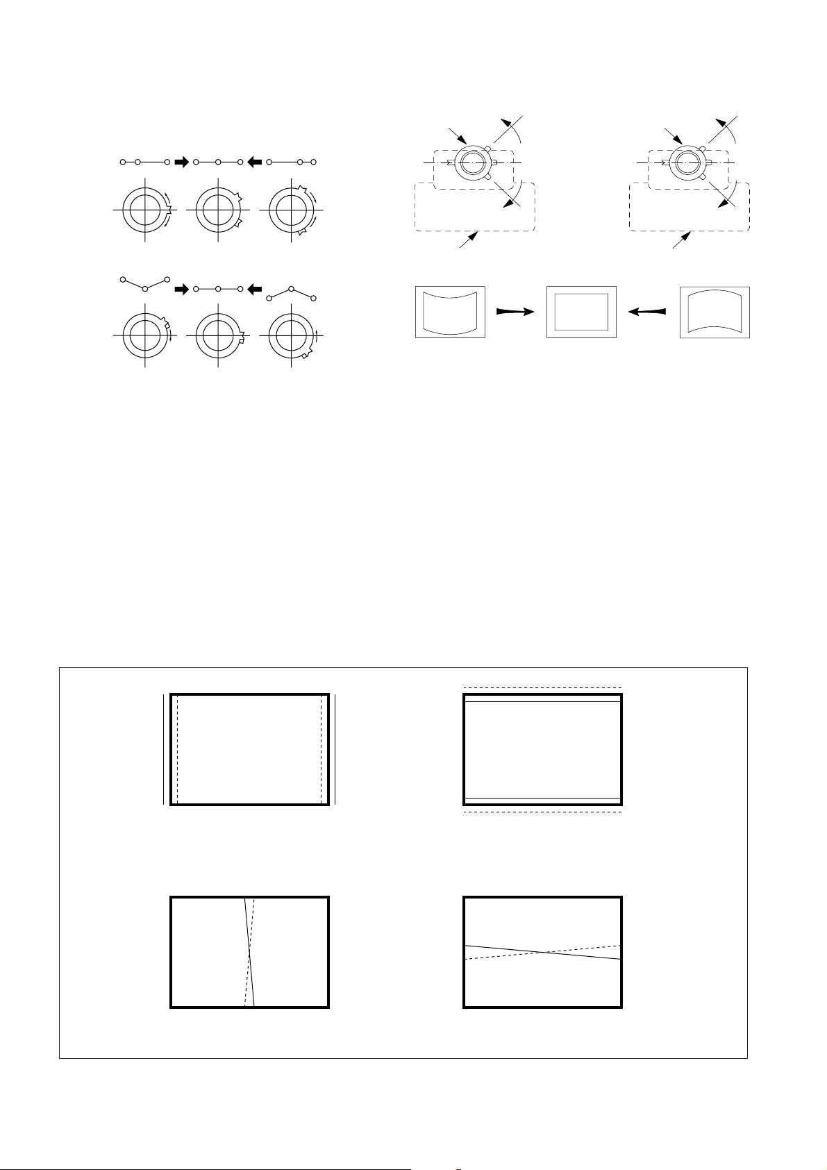
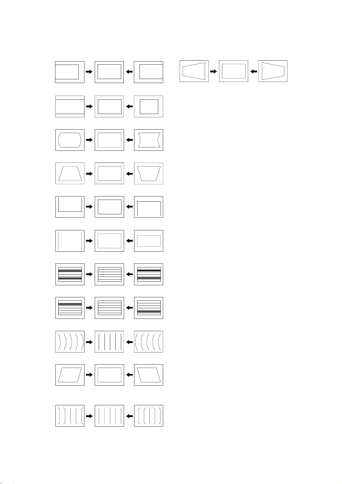
3-7. PICTURE DISTORTION ADJUSTMENT (1)
Item Number 00 – 0B
GEO 0 HPS (H POSITION)
GEO 1 HSZ ( H SIZE)
GEO 2 PAP (PIN AMP)
GEO 3 TLT (TRAPEZIUM)
GEO 4 VPS (V POSITION)
PICTURE DISTORTION ADJUSTMENT (2)
H-TRAPEZOID (ROTATE RVI801)
GEO 5
GEO 6
GEO 7
GEO 8
GEO 9
VSZ (V SIZE)
SCO (VERTICAL S-Correction)
VLN (V LINEARITY)
BOW (AFC. BOW)
AGL (AFC. ANGLE)
GEO 0A
GEO 0B
UPN (UPPER CORNER PIN)
LPN (LOWER CORNER PIN)
– 23 –
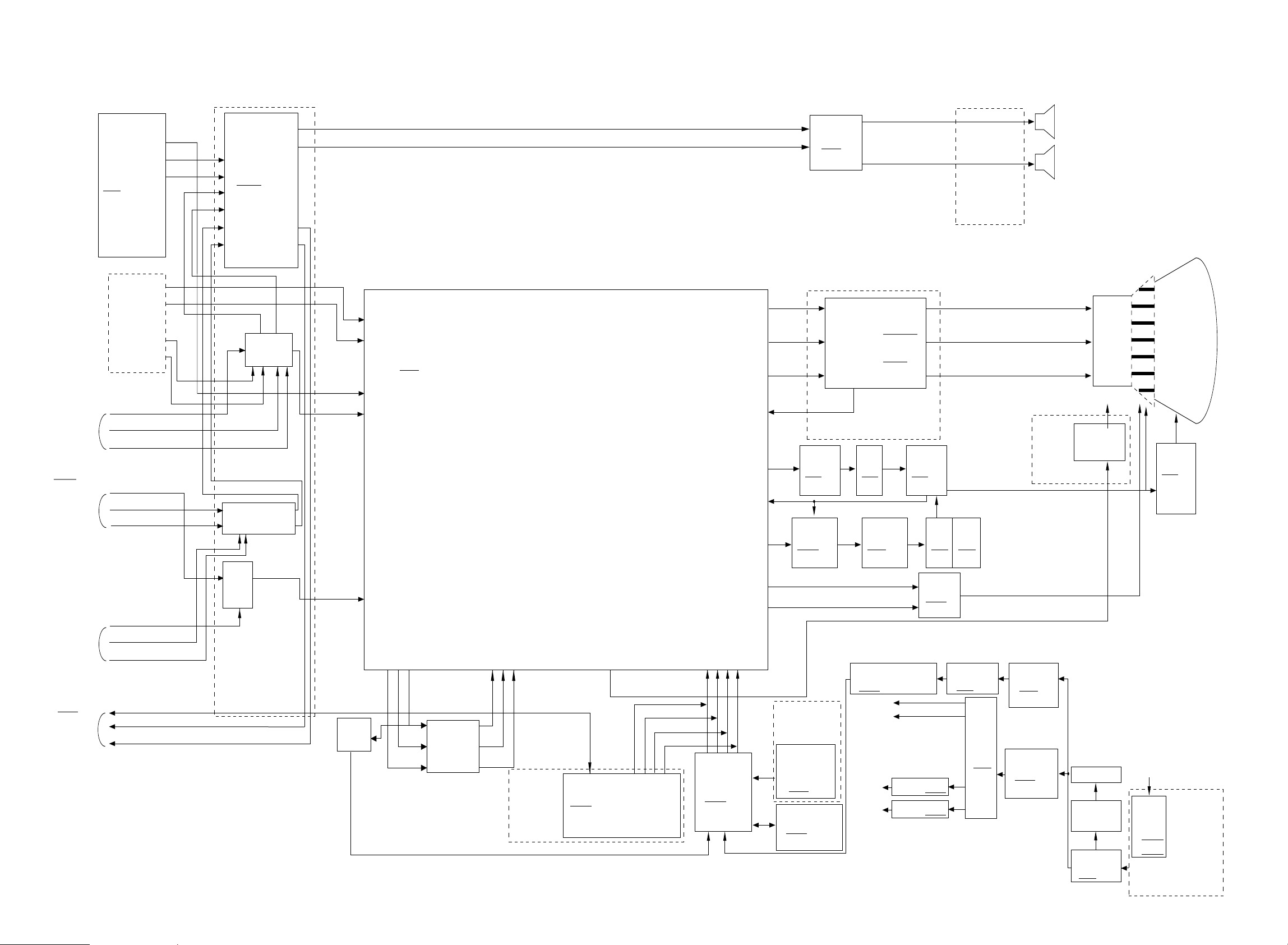
4-1. BLOCK DIAGRAM
SECTION 4
DIAGRAMS
KV-AR25M81A
RM-952
KV-AR25M81A
RM-952
MAIN. TUVIF
<slave: 90H>
TU101
BTF-LG433
<slave:C0H>
VIDEO IN 1
JACK BLOCK
J7402
PIN 9P
VIDEO IN 2
V3 Y in
VIDEO IN 3
(FRONT)
J3903 3P
MONITOR
OUT
J
(DVD
TERMINAL)
V1 Y in
V1 L in
V1 R in
V2 Y in
V2 L in
V2 R in
V3 L in
V3 R in
V out 2
L out 2
R out 2
TV V in
TV L in
TV R in
V
U
L
R
AUDIO
PROSESSOR
IC7203
TDA7429S
<slave: 90H>
R out
L out
IC7501
SWITCH
TV Y in
V I Y in
AUDIO MIXER
IC7204 UPC4558G2
Q7310
CASIO
MIXER
V 2 Y in
B9
(CISPR, AC fuse, A/V Input,
DVD Switch, Monitor Out)
PNC
& ADC
40
41
YC JUNGLE
IC301
CXA2159S
46
<slave:88H>
43
4
A
(System Controller, Y/C Jungle, Deflection, Tuvif, Front Amp, Power Supply)
41 40 39 34 33 32
V out
Y out
U out
Additional
Color Matrix
Y in
V in
U in
TELETEXT
V1
SYSTEM DECODER with
IC801
SAA5261
<slave:88H>
17
VM out
u
com
BLK
28 29 30 31
B G R BLK
SYSTEM
u
com
IC001
CXP86461
R out
24
G out
25
B out
26
IK in
23
H. DRIVE
21
H. PULSE
20
E/W
13
VD+
15
VD-
16
H2
RECEIVER
SIRCS
SBX3081-21
IC3901
MEMORY
I2L
AUDIO OUT
IC201
TA8223K
RED OUT
GREEN OUT
BLUE OUT
(Video Amp, Rotation Circuit)
C6
H-DRIVE
Q506
2SC2785
PIN-CONT
IC502
NJM2903M
(Receiver Power
SW LED)
IC003
M24C08
VIDEO AUP
Q701-712
IC1800
LA6510
HDT
T501
H-OUT
Q511
2SD2578
PIN-OUT
Q505
PMT
T505
IRF614
V-OUT
IC503
TDA8172
5V REG & RESET
IC002 MM1319AFBE
+B
Audio Front Vcc
9V REC IC603
+9V
5V REC IC604
+5V
H1
(Front AV IN, Key SW)
CRT SOCKET
HLT
T504
STB TRANS
T604
SRT
T603
11V
7V
SP ASSY
R out
G out
B out
VM1
(Velocity
Modulation)
STB SW TR
Q605
2SK2845
POWER
IC601
STR-F6656
DY
Y25RSA-Y
NECK ASSY
VM DRIVE
Q5902/5906
DGC
THP
THP600
LINE FILTER
T601
CRT
A60LPN70X
FBT
T503
NX-4009
AC CORD
LINE
FILTER
T7601
T7602
B9
(CISPR, AC fuse, A/V Input,
DVD Switch, Monitor Out)
– 25 –– 24 –
KV-AR25M81A
RM-952
4-2. CIRCUIT BOARDS LOCATION
C6
H2
A
H1
VM1
B9
J
V1
– 26 –
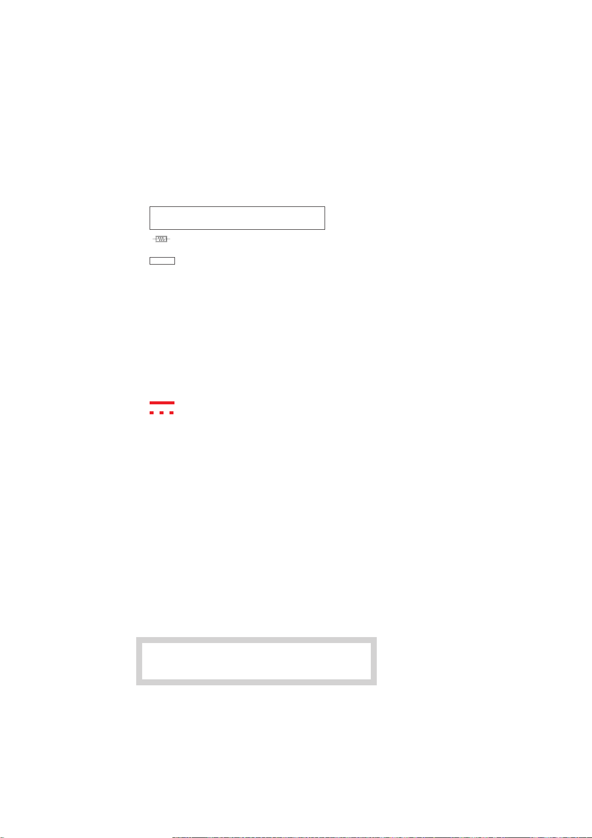
4-3. SCHEMATIC DIAGRAM
Note:
• All capacitors are in µF unless otherwise noted.
• All electrolytic capacitors are rated at 50V unless otherwise
noted.
• All resistors are in ohms.
kΩ = 1000Ω, MΩ = 1000kΩ
• Indication of resistance which does not have rating electrical
power is as follows.
Pitch: 5 mm
Rating electrical power 1/4W (CHIP: 1/10W)
• : nonflammable resistor.
• ¢ : internal component.
• : panel designation or adjustment for rrepair.
• All variable and adjustable resistors have characteristic curve
B unless otherwise noted.
• Readings are taken with a color-bar signal input.
no mark : COMMON
(): PAL
[ ] : NTSC 3.58
• Readings are taken with a 10 MΩ digital multimeter.
• Voltage are dc with respect to ground unless otherwise
noted.
• Voltage variations may be noted due to normal production tolerances.
• All voltage are in Volt.
• ✽ : Cannot be measured.
• Circled numbers are waveform references.
• : B +bus.
• : B –bus.
• ÷ : signal path.
KV-AR25M81A
RM-952
Reference information
RESISTOR : RN METAL FILM
COIL : LF-8L MICRO INDUCTOR
CAPACITOR : TA TANTALUM
Note: The component identified by shading and
: RC SOLID
: FPRD NONFLAMMABLE CARBON
: FUSE NONFLAMMABLE FUSIBLE
: RS NONFLAMMABLE METAL OXIDE
: RB NONFLAMMABLE CEMENT
: RW NONFLAMMABLE WIREWOUND
: ✽ ADJUSTMENT RESISTOR
: PS STYROL
: PP POLYPROPYLENE
: PT MYLAR
: MPS METALIZED POLYESTER
: MPP METALIZED POLYPROPYLENE
: ALB BIPOLAR
: ALT HIGH TEMPERATURE
: ALR HIGH RIPPLE
mark ! are critical for safety. Replace only
with part number specified.
– 27 –
 Loading...