

Page 1
3-862-739-21
FD Trinitron
UTEGA
Trinitron XBR
Operating Instructions
KV-32XBR200 KV-36XBR200
Page 2

Tab le of C ont ents
Welcome!................................................ 7
Precautions
Using This Manual
Connecting and Installing the TV
Making Connections
Note about the AC Power Cord
Cable or Antenna Connections.............................3
Connecting directly to cable or an
Cable and antenna...........................................3
Cable Box Connections........................................4
Cable box .......................................................4
Cable box and cable........................................4
VCR Connections.................................................5
Connecting an antenna/cable TV
Connecting a VCR and TV with a
Connecting two VCR's....................................6
DBS Connections
Connecting a DBS receiver
Connecting a DBS receiver and a
DVD Connections
Connecting a DVD Player
.............................................
..................................
............................................
..........................
antenna
......................................................
system with a VCR
cable box
VCR............................................................7
....................................................
....................................
.................................................
.............................
................................................
..............................
Connecting a DVD Plaver w ith
7
7
2
3
3
5
5
Setting Up the TV Automatically.......................14
Watching the TV
7
Watching Two Programs at One Time -
7
Using CHANNEL INDEX
8
Using your Menus
8
Learning Menu Selection...................................21
component \ ideo output
connectors
Additional Connections........................................9
Connecting an auclio system...........................9
Connecting an A/V receiver............................9
Connecting a camcorder................................10
Using Special Sony Features
Uswrg the CONTROL S feature
Connecting S-Link to your VCR
Connecting S-Link to your DBS
Basic Set Up
Inserting Batteries
Using-the Remote Control Joystick
Adjustment Bars .................................................13
On Screen Help/Instructions
Using your New TV
PIP/P&P (Twin View™)
..................................................
.............................
..............................................
..................;...........
................................................
.................................
..................
..................
...................
....................
..........................
Ouick Start to tire Menus
Using the VIDLCl lliD Menu
8
Using the AUDIC) S Menu ...............................24
Using the TIMER © Menu
Using the SET UP S Menu
Setting and Selecting
11
11
12
12
13
13
13
15
17
19
FAVORITE CHANNEL
Operating Video Equipment
Setting the Manufacturer's Code........................31
Operating a Cable Box or DBS Receiver
Setting the Manufacturer's Code
Troubleshooting......................................34
Specifications
Index
.......................................................
..........................................
...................................
................................
................................
............................
.........................
........................
22
23
25
26
28
33
36
37
Page 3

Re mot e C ontr ol
III llir !Hsln/cii<v/> limi (Г(’ irill
I'thr l() till' luillons on I/O/// mnotc < Olllrol.
Ki'i'i’ ////s flap nnfi’lilrd ami //>(■ ////< papa
for n'frrcih'r.
SYSTEM OFF (page 16)T
SLEEP (page 15)‘
DISPLAY (p^e 16)"
VCR/DVD/MDP
Operation
Buttons
(page 32)
DVD
Operation
Buttons
(page 32)
PIP/P&P
(pages 17, 18)
MUTING“!^
(page 15)
JUMP-
(page 15)
- TV/DBS
VOL +/-
RESET
CODE SET
(pages 31, 33)
I MUTING
VTWDVO D8SC4BLE , ^
CD CD iln))
SrSTSM
OFF
VTRCVt) DBS/C*fll-E TV
CD CD ca
OlSPUl rv/Vl0£0
-m
шИГ®
® ® ®
® ® ®
l(^ (B) (Щ (g);
FUNCTION
Getting to know the buttons on the
remote control
POWER
(page 15) Names ot the Liuttons on the remote
control are presented in ditferent colors hr
FUNCTION represent the a\ ailable fvmctions.
(page 15)
лит/ ■,r\ Button color
ANT (page 16) „ , ,
Black
...............
I'ress to select the component
. you want to control; e.g. VTR
(page IbJ (VCR)/MDP/DVD Player, DBS
0-9 Buttons (Direct Broadcast Satellite)/
EMTER CABl,b:,oi-TV
J
Green ............... ButU)ns relewint to power
Р1Р/Р&Р/ operations, like turning the TV,
CHANNEL INDEX ogg (Direct Broadcast Satellite) /
(pages 17-20) CABLE, or VTR (VCR)/MDP/
bi
MTS/GUIDE LIV'D Idaver on or off
MENU Label color
White
CH +/- Player/DBS (Direct Broadcast
...............
TV/VTR (V'CR)/MDP/DVD
Joystick SateUite)/CABLE operation
(oaae 13) buttons
^ Yellow...............PIP, P&P, and CHANNEL
VTR1/2/3/DVD/ INDEX operation buttons
MDP (page 31)
....................
L)BS (Direct Broadcast Satellite)
operation buttons
Green................S-Link operation buttons
Pink
..................
DVD Player operation buttons
For a lictailed explciimtion of most buttons, src
"Watching the TV" on page 15.
Page 4
WARNING
To reduce the risk of fire or shock hazard, do not
expose the TV to rain or moisture.
CAUTION
RISK OF ELECTRIC SHOCK
DO NOT OPEN
ATTENTION
RISQUE DE CHOC ELECTRIQUE,
NE PAS OUVRIR
PRECAUCION
RIESGO DE CHOQUE ELECTRICO
NO ABRIR
CAUTION: TO REDUCE THE RISK OF ELECTRIC SHOCK,
DO NOT REMOVE COVER {OR BACK).
NO USER-SERVICEABLE PARTS INSIDE.
REFER SERVICING TO QUALIFIED SERVICE PERSONNEL.
This symbol is intended to alert the user to
the presence of uninsulated "dangerous
A
voltage" within the product's enclosure that
may be of sufficient magnitude to constitute
a risk of electric shock to persons.
This symbol is intended to alert the user to
the presence of important operating and
maintenance (servicing) instructions in the
literature accompanying the appliance.
CAUTION
TO PREVENT ELEaRIC SHOCK, DO NOT USE THIS
POLARIZED AC PLUG WITH AN EXTENSION CORD,
RECEPTACLE, OR OTHER OUTLET UNLESS THE BLADES CAN
BE FULLY INSERTED TO PREVENT BLADE EXPOSURE.
CAUTION
When using TV games, computers, and similar products
with your TV, keep the brightness and contrast
functions at low settings. If a fixed (non-moving)
pattern is left on the screen for long periods of time at
a high brightness or contrast setting, the image can be
permanently Imprinted onto the screen. Continuously
watching the same program can cause the imprint of
station logos onto the TV screen. These types of
imprints are not covered by your warranty because
they are the result of misuse.
Note on Caption Vision
This television receiver provides display of television
clos^ captioning in accordance with §15.119 of the
FCC rules.
Note on cleaning the TV
Clean the TV with a soft dry cloth. Never use strong
solvents such as thinner or benzine, which might
damage the finish of the cabinet.
Note to CATV system installer
This reminder is provided to call the CATV system
installer's attention to Article 820-40 of the NEC that
provides guidelines for proper grounding and, in
particular, specifies that the cable ground shall be
connected to the grounding system of the building, as
close to the point of cable entry as practical.
Use of this television receiver for other than private
viewing of programs broadcast on UHF or VHF or
transmitted by cable companies for the use of the
general public may require authorization from the
broadcaster/cable company and/or program owner.
NOTIFICATION
This equipment has been tested and found to comply
with the limits for a Class B digital device pursuant to
Part 15 of the FCC Rules. These limits are designed to
provide reasonable protection against harmful
interierencf in u residential installation. This
equipment generates, uses, and can radiate radio
frequency energy and, if not installed and used in
accordance with the instructions, may cause harmful
interference with radio communications. However,
there is no guarantee that interference will not occur
in a particular installation. If this equipment does
cause harmful interference to radio or television
reception, which can be determined by turning the
equipment off and on, the user is encouraged to try to
correct the interference by one or more of the
following measures;
• Reorient or relocate the receiving antennas.
• Increase the separation between the equipment and
receiver.
• Connect the equipment into an outlet on a circuit
different from that to which the receiver is
connected.
• Consult the dealer or an experienced radio/TV
technician for help.
You are cautioned that any changes or
modifications not expressly approved in this
manual could void your authority to operate this
equipment.
This document is for the remote control RM-Y144.
MODELS: KV-32XBR200, 36XBR200
As an ENERGY STAR* Partner.
Sony has determined that
this product or product
models meets the ENERGY
STAR« guidelines for energy
efficiency.
ENERGY STAR® is a U.S. registered mark.
t I
Page 5
Additional Connections
Connecting an audio system
For an enhanced sound, connect your audio
system to your TV.
1 Using AUDIO connectors, connect AUDIO
OUT on your TV to one of the unused Line
inputs (e.g. Tape-2, AUXl, etc.) on your
stereo.
2 Set your stereo to the chosen Line input
and use the AUDIO menu to set your
audio output, (see "SPEAKER" and
"AUDIO OUT" on page 24)
Connecting an A/V receiver
For easier control of all audio and video
equipment, connect your A/V receiver.
1 Using A/V connectors, connect VIDEO 1
IN on your TV to Monitor AUDIO and
VIDEO OUT on your A/V receiver.
2 Using A/V connectors, connect TV OUT
on your TV to TV AUDIO and VIDEO IN
on your A/V receiver.
You may want to use CHANNEL FIX to fix your TV's
input to the AA' receiver (VIDEO 1). (see "CHANNEL
SET UP" on page 26)
(K. ... ■)!
Disconnect all power sources before making any connections.
Page 6

fi*: Co nnec tino
Making Connections
Refer to the table below, it will direct you to the diagram suitable to the components you will be
connecting.
lf youv№l1il>iwnn(Scting ^ ~ See page
Cable or antenna only
Cable and antenna
Cable box
Cable box and cable to view scrambled channels
VCR and cable or antenna
VCR and cable box
Two VCRs tor tape editing using MONITOR OUT'
Direct Broadcast Satellite Receiver (DBS)
VCR and Direct Broadcast Satellite Receiver (DBS)
DVD Player
DVD Player with component video output connectors
Audio system
A/V receiver
Camcorder to view tapes
CONTROL S
VCR using S-Link
Direct Broadcast Satellite Receiver (DBS) using S-Link
3
3
4
4
5
5
6
7
7
8
8
9
9
10
11
12
12
Page 7
Note about the AC Power Cord
The AC power cord is attached to the rear of
the TV with hooks. Use caution when
removing the AC plug from its holder. Gently
slide the cord in the upward direction,
without removing the cord from the two
lower hooks.
You can
Do not remove
the cord from
these hooks.
Cable or Antenna Connections
Connecting directly to cable or an antenna
The connection you choose will depend on the
cable found in your home. Newer homes will
be equipped with standard coaxial cable (see
A); older homes will probably have 300-ohm
twin lead cable (see B); still other homes may
contain both (see C).
VHF only
or
VHF/UHF
or
Cable
VHF only 300-ohm twin
75-ohm coaxial cable
VHF f
and
UHF
300-ohm twin lead cable
75 ohm
coaxial cable
lead cable
Antenna connector
(Redr of TV)
VHF/UHr
(Rear of TV)
VHF/UHF
A
(Rear of TV)
VHF/UHF
EAC-66 U/V mixer
(not supplied)
Cable and antenna
You may find it convenient to use the
following set up if your cable provider does
not feature local channels that you are able to
receive using an antenna.
(Rear of TV)
CATV cable
(No connection "TO
CONVERTER" in this case)
Antenna cable
do
AUX
TO CONVERTER
VHF/UHF
Select cable or antenna mode by pressing
ANT on the remote control.
Note
• In order to receive channels with an
antenna, you will need to turn your
CABLE to OFF and perform the AUTO
PRCKTRAM function, (see "CHANNEL
SET UP" on page 26)
Page 8

Connecting and
l i:
Cable Box Connections
Some pay cable TV systems use scrambled or
encoded signals that require a cable box to
view all channels.
Cable box
1 Connect the coaxial connector from your
cable to the IN on your cable box.
2 Using a coaxial cable, connect OUT on
your cable box to VHF/UHF on your TV.
Cable box and cable
For this set up, you can switch between
scrambled charmels (through your cable box),
and normal (CATV) channels by pressing
ANT on your remote control.
Notes
• Your Sony remote control can be
programmed to operate your cable box.
(see "Operating a Cable Box or DBS
Receiver" on page 33)
• When using PIP, you cannot view the
AUX input in the window picture.
Tip V
Pressing ANT switches between these inputs.
If you will be controlling all channel selection through
your cable box, you should consider using the CHANNEL
FIX feature, (see “CHANNEL SET UP" on page 26)
Cable
1 Í
IN
Cable box
If you are connecting a cable box through the AUX input and would like
to switch between the AUX and normal (CATV) input you should consider
using the CHANNEL FIX feature, (see “CHANNEL SET UP" on page 26)
Cable box
scrambled
channels
^CD=p=<D—»€8)
CATV cable
(unscrambled channels)
OUT
75-ohm coaxial
cable (not supplied)
(Rear of TV)
VHF/UHF
(Rear of TV)
AUX
TO CONVERTER
♦
(signal)
VHF/UHF
Page 9

VCR Connections
Connecting an antenna/cable TV
system with a VCR
1 Attach the coaxial connector from your
cable or antenna to IN on your VCR.
2 Using A/V connectors, connect AUDIO
and VIDEO OUT on your VCR to AUDIO
and VIDEO IN on your TV*.
3 Using a coaxial connector, connect OUT on
your VCR to VHF/UHF on your TV.
* If you are connecting a monauraJ VCR, connect only the
single white audio output to the left input on your TV,
Connecting a VCR and TV with a cable box
1 Coimect the single (input) jack of the
splitter to your incoming cable connection,
and connect the other two (output) jacks
(using coaxial cable) to IN on your cable
box and VHF/UHF on your TV.
2 Using a coaxial connector, connect OUT on
your cable box to IN on your VCR.
3 Using A/V connectors, connect AUDIO and
VIDEO OUT on your VCR to AUDIO and
VIDEO IN on your TV.
Disconnect all power sources before making any connections.
For optimum picture quality, use S VIDEO
instead of the yellow A/V cable. S VIDEO does
not provide sound, your audio connectors
must still be connected.
Coaxial cable
Cable
1 1^-13 >
(not supplied)
Cable
1 ——GO-'®
Splitter
Cable box
AUnOfl «(WOt. WCO 8W0E0
VCR
---------------------1------------
VMC-810S/820S (not supplied)
«aO'—®
(Rear of TV)
(Rear of TV)
----
AUDIO-R(red)
AUDIO-L (white)
VIDEO (yellow)
Page 10
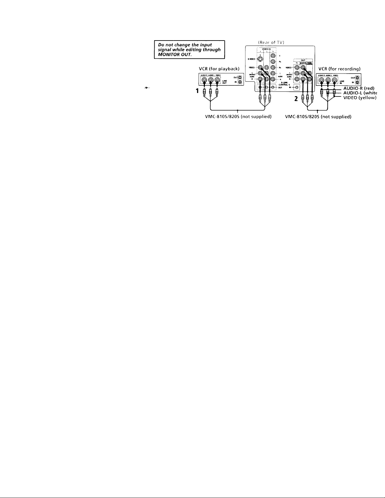
Connecting and Insialliny
Connecting two VCRs
MONITOR OUT gives you the ability to use a
second VCR to record a program being played
by the primary VCR or to perform tape
editing and dubbing.
1 Connect the VCR intended for playback
using the connection instructions on page
4 of this manual.
Using A/V connectors, connect AUDIO
and VIDEO IN on your VCR intended for
recording to MONITOR AUDIO and
VIDEO OUT on your TV.
Disconnect all power sources before making any connectioi
Page 11
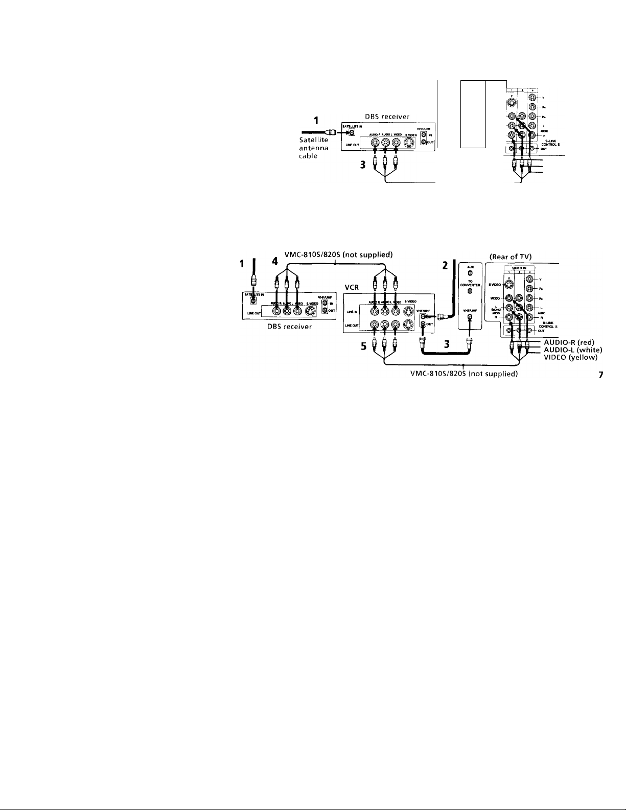
DBS Connections
Connecting a DBS (Direct Broadcast
Satellite) receiver
1 Connect the cable from your satellite
antenna to your DBS receiver.
2 Attach the coaxial connector from your
cable or antenna to VHF/UHF on your TV.
3 Using A/V connectors, connect AUDIO
and VIDEO OUT on your DBS receiver to
AUDIO and VIDEO IN on your TV.
Connecting a DBS (Direct Broadcast Satellite) receiver and a VCR
1 Connect the cable from your satellite
antenna to your DBS receiver.
2 Attach the coaxial connector from your cable
or anterma to VHF/UHF IN on your VCR.
3 Using a coaxial connector, connect VHF/
UHF OUT on your VCR to VHF/UHF on
your TV.
4 Using A/V cormectors, connect AUDIO
and VIDEO OUT on your DBS receiver to
AUDIO and VIDEO IN on your VCR.
5 Using A/V connectors, connect AUDIO
and VIDEO OUT on your VCR to AUDIO
and VIDEO IN on your TV.
Disconnect all power sources before making any connections.
For optimum picture quaiity, use S VÌDEO
instead of the yellow A/V cable. S VIDEO does
not provide sound, your audio connectors
must still be connected.
Pressing TV/VIDEO on the remote control will
allow you to view from the DBS or VCR.
2 (Real ol TV)
0
SVBEO-
CONVERTER
0
VCEO -
VHFAIHF
Loflj
-*©
VMC-810S/820S (not supplied)
(»«r
AUDIO-R (red)
AUDIO-L (white)
VIDEO (yellow)
Page 12
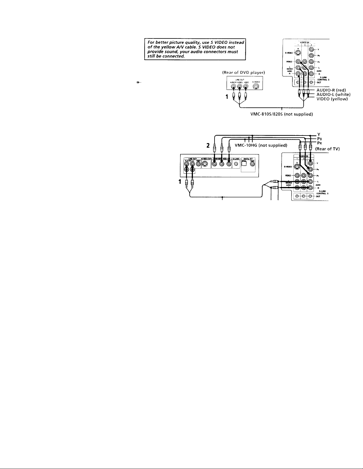
DVD Connections
Connecting a DVD Player
Using A/V connectors, connect VIDEO IN on
your TV to LINE OUT on your DVD Player.
Connecting a DVD Player with component video output connectors
This connection option offers the highest
quality DVD picture.
1 Using AUDIO connectors, connect AUDIO
R and L of the LINE OUT on your DVD
Player to AUDIO R and L on the VIDEO IN
4 panel at the rear of your TV.
2 Using three VIDEO connectors, connect Y,
Pb, and Pr on the COMPONENT VIDEO
OUT on your DVD Player to Y, Pb, and Pr
on the VIDEO IN 4 panel at the rear of
your TV.
Note
• Some DVD Player terminals may be
labeled Y, Cb, and Cr, or Y, B-Y, and R-Y.
If so, connect them by matching the colors.
8
DVD
Disconnect all power sources before making any connection
iK.-.ir of TV,
RK-74A (not supplied)
AUDIO-R AUDIO-L
(red) (white)
Page 13

Additional Connections
Connecting an audio system
For an enhanced sound, connect your audio
system to your TV.
1 Using AUDIO connectors, connect AUDIO
OUT on your TV to one of the unused Line
inputs (e.g. Tape-2, AUXl, etc.) on your
stereo.
2 Set your stereo to the chosen Line input
and use the AUDIO menu to set your
audio output, (see "SPEAKER" and
"AUDIO OUT" on page 24)
Connecting an A/V receiver
For easier control of all audio and video
equipment, connect your A/V receiver.
1 Using A/V connectors, connect VIDEO 1
IN on your TV to Monitor AUDIO and
VIDEO OUT on your A/V receiver.
2 Using A/V connectors, connect TV OUT
on your TV to TV AUDIO and VIDEO IN
on your A/V receiver.
You may want to use CHANNEL FIX to fix your TV's
input to the AA' receiver (VIDEO 1). (see "CHANNEL
SET UP" on page 26)
(K. ... ■)!
Disconnect all power sources before making any connections.
Page 14

KK' Connecting and ins:c.
Connecting a camcorder
This connection is convenient for viewing a
picture directly from your camcorder.
Using A/V connectors, connect AUDIO and
VIDEO OUT on your camcorder to AUDIO
and VIDEO IN on your TV.
Connection can also be made directly to your
A/V input located on the rear of your TV.
Note
• If you are connecting a monaural camcorder,
connect only the single white audio output
to the left input on your TV.
Disconnect all power sources before making any connectior
If you have an S VIDEO equipped camcorder,
you can use an S Video cable for optimum
picture quality.
10
Page 15

Using Special Sony Features
Using the CONTROL S feature
CONTROL S allows you to control your TV
and other Sony equipment with one remote
control.
To control your other Sony equipment with
your TV's remote control, connect the
CONTROL S IN jack of the equipment to the
CONTROL S OUT jack on the TV with the
CONTROL S cable.
To control other Sony equipment with your
TV's remote control, see "S-Link Connections"
on page 12.
Disconnect all power sources before making any connections.
(Rear of TV)
11
Page 16

Connecting and Instaiir
Connecting S-Link to your VCR
S-Link will automatically power on the TV and
switch to the correct video input when a tape is
inserted in the VCR or when you begin to play
a tape.
1 Using A/V connectors, connect AUDIO and
VIDEO OUT on your VCR to AUDIO and
VIDEO IN on your TV.
2 Using an S-LINK connector (mono mini
plug), connect S-LINK/CONTROL S-IN on
your VCR to S-LINK on your TV.
Connecting S-Link to your DBS
S-Link will automatically power on the TV and
switch to the correct video input when you
power on the DBS.
1 Using A/V connectors, connect AUDIO and
VIDEO OUT on your DBS to AUDIO and
VIDEO IN on your TV.
2 Using an S-LINK connector (mono mini
plug), connect S-LINK/CONTROL S-IN on
your DBS to S-LINK on your TV.
Note
• If you have labeled one of your video inputs
as SKIP (see "VIDEO LABEL" on page 27)
and then connect video equipment to this
input using S-Link, the S-Link feature will
override the SKIP function.
12
Disconnect all power sources before making any connectioi
The S-Link connector must be in the same
VIDEO-IN jacks as the A/V cables on your TV.
DBS
(Rear of TV)
Page 17

C.‘.
Inserting Batteries
Insert two size AA (R6) batteries (supplied) by
matching the + and - on the batteries to the
diagram inside the battery compartment.
Notes
• Remove the batteries to avoid damage
from possible battery leakage whenever
you anticipate that the remote control will
not be used for an extended period.
• Handle the remote control with care.
Avoid dropping it, getting it wet, or
placing it in direct sunlight, near a heater,
or where the humidity is high.
• Your remote control can be programmed to
operate most video equipment.
(see "Operating Video Equipment" on
page 31)
Using the Remote Control
Joystick
Select
The supplied remote control has a joystick
which allows for movement of the on-screen
selector. Pressing up, down, left, or right on
the joystick will cause the selector to move in
the corresponding direction. Pressing down
on the center of the joystick ( © ) will select
the item.
Adjustment Bars
When menu items present an adjustment bar
( mwm'— or KHiuuwImuiuiuiu ), press up, down, left, or
right on the joystick to adjust the setting.
On Screen Help/lnstructions
Several menu windows will provide prompts
and instructions to assist you in navigating
through the different functions.
When the instructions are presented, use them to
supplement the instructions in this manual.
13
Page 18

/fe
Setting Up the TV Automatically
The Easy Setup Guide feature allows you to
set the on-screen language and set all
receivable channels in one step.
The AUTO PROGRAM function of the Easy
Setup Guide feature does not apply for
installations that use a cable box for ail channel
selection.
You can also set up the TV manually, (see "Usiny
the SET UP menu" on paye 26)
I'i’ps V
• Perform this function duriny the day, loith the
antenna andfor cable properly connected, to ensure
that all available channels will he broadcasting and
receivable.
• After using Easy Setup Guide you will still have the
option of adjusting any of the system settings, like
erasing channels, through the SET UP menu, (see
"CHANNEL SET UP" on page 26)
14
L'sing the buttons on the lop ol the I \
D Q Q D 3 3 G
SCT'jF TVVC'EC ■ VC'e.Mt ♦ ■■ CHANNEL + POWER
1 Press POWER to turn on the TV.
'*^The Easy Setup Guide screen appears.
ENGLISH ' CH * [
ESPANDI CM ■ '
FRANÇAIS ; VOL . ]
AUTO SF r UP i VOL I
C®
pnwPD
2 Press CHANNEL + to select ENGLISH,
CHANNEL - to select ESPAÑOL or
VOLUME -r to select FRANÇAIS.
The screen will change to reflect your
choice.
DEMO (TV ■■■VIDEO I
ENGLISH [OH.]
ESPAÑOL: ICH-I
FRANÇAIS'
AUTO AJUSTES [ VOL >
B
DEMO- 1 TV/VIDEO]
Primero conecte e
cabie/antena
Oprima [SET UP|
para salir.
1VOL * 1
For a DEMO of functions and menus,
press TV/VIDEO.
’re--^\’l1| L .MI - to continue
Q
AUTO PROGRAM appears and the TV starts
scanning and presetting channels
automatically. When all the receivable channels
are stored, the lowest numbered channel is
displaved. If the TV receives cable TV channels
CABLE is set to ON automatically.
To perform AUTO SET UP again
Press the SET UP button on the TV and follow
steps 2-3.
Notes
• Before you perform Easy Setup Guide again,
make sure that the input from ANT (not
AUX) is selected by pressing ANT until
"AUX" does not appear next to the channel
number.
• When vou perform AUTO PROGRAM, your
CHANNEL FIX, TIMER, and CHANNEL
BLOCK settings will be erased.
• To reset your TV to factory settings, turn the
TV on. Then, while pressing the RESET
button on your remote control, press the
POWER key on your TV. The TV will turn
itself off, then back on.
Page 19

Watching the TV
Man\' TV features can be accessed directly
through the remote control. The following
chart will explain the function of some
buttons found on your remote control.
Using the White Labeied Buttons for TV Operations
POWER
VTfVDVO Da&iCABLE ,
CD CD ; 0
FUNCTHJN
mVDVD OeS«iABLE TV
CO CD O
Press when you want to turn equipffrent on and off.
Press when you want to control connected components with your remote control, (see
pages 31-33 tor instructions on programming your remote control)
Use for direct channel selection. Press 0-9 to select a channel (for example, to select
and ENTER
CH
a
channel 10, press 1 and 0), the channel will change after 2 seconds, or you can
press ENTER for Immediate selection.
Press to scan through the channels.
Keeping the CH + or- pressed allows you to rapidly scan to the desired channel.
©i
VOL
Press to adjust the volume.
REFER TO THE ILLUSTRATION OF THE
REMOTE CONTROL ON THE INSIDE
FRONT COVER OF THIS MANUAL AS
YOU REVIEW THIS CHART
JUMP
O
MUTING
o
FREEZE
CD
SLEEP
CD
Press to alternate or jump back and forth between two channels. The TV will jump
between the current channel and the last channel selected using the 0-9 buttons.
Press to mute the sound (“MUTING” will appear on the screen). Press again or press
VOL -f to restore sound.
Press to freeze the picture.
Press again or press (off) to cancel.
Press repeatedly until the TV displays the approximate time in minutes (30, 60, or
90) that you want the TV to remain on before shutting off automatically.
Cancel by pressing until SLEEP OFF appears.
15
Page 20

Usniq vo'ji New TV (continued)
16
DISPLAY
CD
TV/VIDEO
CD
ANT
Q
:AUX
GUIDE
(mts)
SYSTEM
OFF
CD
TVA/TR
O
TV/DBS
(D
Using the White Labeled Buttons for TV Operations
Press repeatedly to step through available displays;
Status
Channel number, current time, channel caption (if set), and MTS mode (if SAP is
selected) are displayed. SAP indication disappears after three seconds.
Caption Vision/XDS
Closed captioning or XDS will be displayed on the screen if the broadcaster offers
these services, (see right)
To cancel the display, press DISPLAY repeatedly until DISPLAY OFF appears.
Press repeatedly to step through available video inputs:
TV, VIDEO 1, VIDEO 2, VIDEO 3 and VIDEO 4
If you select SKIP as a VIDEO LABEL in the SET UP menu, your TV will skip the
video input you selected, (see “VIDEO LABEL" on page 27)
Press to change between the VFIF/UFIF input and the AUX input. (For detailed
conriection information, see “Cable4dox and cable” on page 4 or “Cable and
antenna” on page 3)
Press to change from VIDEO input to TV input.
Press to cycle through the Multi-channel TV Sound (MTS) options.
STEREO, SAP, MONO (see “MTS” on page 24)
Guide is a feature of DBS, refer to your DBS operating instructions.
Press to turn off the TV and all other equipment connected with S-Link. (see page 12)
Press when you are finished using a VCR and you want to switch to the TV input.
Your VCR power will remain on.
Press to select an audio option, (see “EFFECT” on page 24) Options:
TRUSURROUND Dolby Virtual
SIMULATED
EFFECT OFF
TV/DBS is a feature of DBS, refer to your DBS operating instructions.
CAPTION VISION
CAPTION VISION can be used for programs
that are broadcast with closed caption.
To access CAPTION VISION:
1 Press MENU.
2 Use the to scroll to fSl.
3 Select EB with the 0 button.
4 Choose a CAPTION VISION option.
5 Access CAPTION VISION/TEXT/XDS
through your DISPLAY button, (see left)
CC1,2, 3or4
Shows you a printed version of the dialog or
sound effects of a program. (The mode should
be set to CC1 for most programs)
TEXT1,2, 3or4
Shows you network/station information
presented using either half or the whole screen.
XDS (Extended Data Service)
Shows a network name, program name,
program length, and time of the show if the
broadcaster offers this service.
Note
• Poor reception of TV programs can cause
errors in CAPTION VISION and XDS.
Captions may appear with a white box or
other errors instead of intended text.
Page 21

Watching Two Programs at One Time — PIP/P&P (Twin View™)
The Picture-irv-Picture (PIP) feature allows you
to view two channels simultaneously, one in
the full size '"main" picture and one in a
smaller "window" picture.
The sound of the main
picture is received
Main picture
channel or inputsource mode
Window picture
- channel or input-
source mode
. Window
picture
Using the Yellow Labeled Buttons for PIP Operations
Some control buttons for PIP and P&P are located under
the cover on the top of the remote control.
Press to display a window picture (PIP).
o
Each time you press, the picture size will change (1/4 ^1/9 —*1/16).
Press
(OFF)
to remove the window picture. ^'
REFER TO THE ILLUSTRATION OF
THE REMOTE CONTROL ON THE
INSIDE FRONT COVER OF THIS
MANUAL >45 YOU REVIEW THIS
CHART
The Picture-and-Picture (P&P) feature allows
you to view two channels simultaneously,
both in a reduced size screen. The main
picture will appear on the right.
Left picture channel
or input-source mode
The sound of the right
picture is received
Right picture
channel or inputsource mode
- Main
picture
(3)
TV/VIDEO
CD
ye/ioix ¡aoeied button
AUDIO
Q
Press to display right (main) and left pictures (P&P).
Press (OFF) to cancel.
Press repeatedly to step through available video inputs:
TV, VIDEO 1, VIDEO 2, VIDEO 3 and VIDEO 4
PIP will display the video source in the window picture.
P&P will display the video source in the left picture.
If you label one of your VIDEO inputs as SKIP, this video input will be
skipped, (see “VIDEO LABEL” on page 27)
Press to alternate sound between the main picture and the window picture
for PIP and the right and left picture tor P&P. A J' will appear for a few
seconds to indicate which picture is receiving sound.
17
Page 22

i Using your New TV (continued)
CH +
CD
CH-
CD
POSITION
Q
FREEZE
CD
SWAP
CD
Using the Yellow Labeled Buttons for PIP Operations
Press to change the TV channel in the secondary picture.
For PIP, the channel in the window picture will change.
For P&P, the channel in the left picture will change.
Press to move the location of the window^eicture around the main picture.
This function works only for PIP.
Great for copying down phone numbers, addresses, recipes, etc.
For PIP: Press to freeze the main picture and remove the window picture.
Press O or FREEZE to resume PIP viewing.
Press (OFF) to cancel and resume normal TV viewing.
For P&P: Press to freeze both pictures.
Press again to resume P&P viewing or press /off) to cancel and resume
normal TV viewing.
Press to switch the audio and video of the main picture and the window picture for PIP, or
between the left and right pictures for P&P.
Press to access CHANNEL INDEX for direct channel selection, (see “Using CHANNEL
INDEX” on page 19)
Press to cancel PIP or P&P functions and return to normal viewing.
Notes
• The channel being received through the
AUX jack cannot be displayed as a
window picture.
• If one of the pictures received through
PIP/P&P is snowy, the entire screen may
appear snowv. In this case, skip the snowy
channel. (see'XHANNEL SKIP/ADD" on
page 26)
18
Page 23

Using CHANNEL INDEX
2 Use the jovstick to move the vellow frame
You can use the CHANNEL INDEX feature to
display multiple channels for direcf selection.
Channels used for CHANNEL INDEX will
come directly from the TV's list of receivable
channels (those set during AUTO PROGRAM
or through the SET UP menu).
1 Press (S) once to display the current
channel in the center of the screen
surrounded by the first twelve receivable
channels.
You can press
again for another set
of 12 channels.
to the desired channel and press y .
C’
4
The selected channel is displayed for
normal viewing.
If one of the pictures received through
CHANNEL INDEX is snowv, the entire
screen mav appear snowv. In this case,
erase the snowy channel using CHANNEL
SKIP/ADD. (see "CHANNEL SET UP" on
page 26)
4-
.■tf
A yellow frame will appear to indicate
current channel selection.
Notes
• You cannot move the yellow frame until
all of the surrounding pictures appear.
• The TV will continually update each of the
surrounding pictures while the
CHANNEL INDEX screen is displayed.
• Sound will only be heard from the center
picture while the CHANNEL INDEX
screen is displayed.
19
Page 24

Using your New TV (continued)
Using the Yellow Labeled Buttons for CHANNEL INDEX Operations
Some control buttons are located under the cover
on the top of the remote control.
Press to access CHANNEL INDEX.
Press again to access the next twelve receivable channels.
CH +
O
CH-
Q
Press to cycle through the receivable (jjTannels one at a time.
Press to cancel the. current operation and return to normal TV viewing.
FREEZE
Q
TV/VIDEO
CD
ANT
CD
CH
Press to freeze the center picture.
Press again to cancel the frozen picture and resume normal center picture viewing.
Using the White Labeled Buttons for Center Picture Operations
Press to cycle the center picture through the video inputs.
The surrounding channels will not change.
Press to replace the center picture with a channel received through the AUX input.
Press again to return to CATV input.
Press to select the channel for the center picture,
®-(9)
or Vi/ Vi/ or
and ENTER
JUMP
O
(see “Watching the TV” on pages 15-16)
a
REFER TO THE ILLUSTRATION OF THE
REMOTE CONTROL ON THE INSIDE
FRONT COVER OF THIS MANUAL AS
YOU REVIEW THIS CHART
20
Page 25

Using your Menus
Learning Menu Selection
Use the MENU button to access a menu and
use the joystick to alter settings. Use the
following example, in which we activate, the
CABLE, to learn how to modify settings.
1 Press the MENU button.
The main menu appears.
VIDEO
►
MODE VIVID
Pir-TIIRP
BRIGHTNESS —III
O
MENl^^
Press up or down on the joystick to
highlight the desired menu and press 0
to activate it.
HUE
e
TRINITONE. HIGH
COLOR CORRECT OFF
ES
OMENU
31 SeieciG Exit ®
SETUP
oni
CHANNEL SET UP
FAVORITE CHANNEL
VIDEO LABEL
LANGUAGE; ENGLISH
©
TILT CORRECTION 0
DMENU
Move )I SelectSl Exit ^
3 Press up or down on the joystick until the
cursor points to the desired option.
SET UP
► CHANNEL SET UP
FAVORITE CHANNEL
VIDEO LABEL
LANGUAGE ENGLISH
TILT CORRECTION 0
OMENU
Press
Options for your selection will be
displayed.
CHANNEL SET UP
► CABLE OFF
CHANNEL FIX OFF
AUTO PROGRAM
CHANNEL SKIP .' ADO
CHANNEL CAPTION
DMENU
5 Press up or down on the joystick to make
vour selection and press ,, L to activate it.
CHANNEL SET UP
► CABLE ON
CHANNEL FIX ON
AUTO PROGRAM
CHANNEL skip; ADO
CHANNEL CAPTION
OMENU
<eO! SeleciQ
When you are done with changes to the
selected menu, choose OMENU to return to
the main menu.
SETUP
► CHANNEL SET UP
FAVORITE CHANNEL
VIDEO LABEL
LANGUAGE. ENGLISH
TILT CORRECTION 0
OMENU
Notes
• Pressing MENU on the remote control will
allow you to exit from the menus at any
time.
• If any menu items are "grayed out" press
the ANT button on your remote control
until a channel number appears.
21
Page 26

Using your Menijs (continued)
Quick start to the menus
The following is a guide to your menus.
For detailed information on using the remote
control to modify menu settings, refer to
"Learning menu selection" on page 21.
To select a menu:
D i s p l a y H i g l i l i g h ! S e l e c t
♦
VIDEO
► MODE. VIVID
PICTURE
BRIGHTNESS
COLOR
©
HUE
SHARPNESS IIIHNUnill
TRiNiTONE HIGH
COLOR CORRECT OFF
E3
OMENU
Move Ql Select^
AUDIO
Im)
► TREBLE
BASS
BALANCE
EFFECT: OFF
©
MTS: STEREO
SPEAKER: ON
AUDIO .DU' ■
OMENU
TIMER
QjT)
► DAYLIGHT SAVING. YES
.
CURRENT TIME SET
*
ON . OFF TIMER
CHANNEL B1 OOK
DMENU
e
MoveWI Seiecttii Exit
SET UP
► CHANNEL SET UP
FAVORITE CHANNEL
VIDEO LABEL
LANGUAGE. ENGLISH
TILT CORRECTION: 0
DMENU
Ea
Move 04 Select 0
The VIDEO menu allows you to make adjustments to your picture setting:
It also allows you to customize the picture MODE based on the type of
........
I
iHnHmiiiiii'
miiiiiiiiiii....................
program you are watching.
The AUDIO menu offers enhanced audio options such as listening to
................
second audio programming (SAP), or customizing the EFFECT of the
sound on your TV.
The TIMER menu sets the clock on your TV and allows you to program
your TV for scheduled viewing using the ON/OFF TIMER.
— : — AM
The SET UP menu provides several options for
setting up your channels, labeling your TVA/IDEO
inputs, and selecting the LANGUAGE of your menus.
The CFIANNEL SET UP menu is a sub-menu which
provides further options for setting up your TV.
CHANNEL SET UP
► CABLE ON
CHANNEL FIX OFF
AUTO PROGRAM
CHANNEL SKIP; ADO
CHANNEL CAPTION
OMENU
MoveQ« Select Q Exit
22
Page 27

Using the VIDEO Oji] Menu
VIDEO
► MODE VIVID
PICTURE
BRIGHTNESS IHHIIttlllll
COLOR HimilHIIIII
©
HUE «I
SHARPNESS HIIHIIIIIIIIII'
TRINITONE HIGH
COLOR CORRECT OFF
E3
DMENU
Move Q* Select*3^
____________
For detailed information on using the remote
control to modify menu settings, refer to
"Learning Menu Selection" on page 21.
To select the VIDEO [m] menu:
D i s p l a y H i g h l i g h t
(Hi)
I Adjiistment
r Bars
Exit №3
S e l e c t
MODE VIVID: Select for enhanced picture contrast and sharpness.
STANDARD: Select to display a standard picture.
MOVIE: Select to display a softer picture.
SPORTS: Select to display a bright picture.
You can alter the VIDEO menu settings (e.g., PICTURE, HUE) for each MODE.
Select each MODE individually and then press RESET to restore factory settings.
.^PICTURE
Pictufe contrast Adjust left to decrease picture contrast and soften the color.
BRIGHTNESS Adjust right to brighten the picture.
Picture actiustment
COLOR Adjust right to increase color intensity.
.Coku saturation
HUE
Color tones
Adjust right to increase picture contrast and create more vivid color.
Adjust left to darken the picture.
Adjust left to decrease color intensity.
Adjust right to increase the green tones.
Adjust left to decrease the green tones.
To restore the factory VIDEO settings
Press RESET on the remote control while the
VIDEO menu is selected.
SHARPNESS
Picture aelail
TRINITONE
White intensity
adjustment
COLOR
CORRECT
Color ratio
ady.stment
Adjust right to sharpen the picture.
Adjust left to soften the picture.
HIGH: Select to give the white colors a blue tint.
MEDIUM: Select to give the white colors a neutral tint.
NTSC STD; Select to give the white colors a red tint.
Select ON to emphasize reds and blues.
Select OFF to emphasize greens.
23
Page 28

Using your Menus (continued)
Using the AUDIO i' Menu
AUDIO
©
► TREBLE
BASS
BALANCE
EFFECT: OFF
©
MTS: STEREO
SPEAKER: ON
AUDIO OUT- variable
OMENU
For detailed information on using the remote
control to modify menu settings, refer to
"'Learning Menu Selection" on page 21.
To select the AUDIO J' menu:
D i s p l a y H i g h l i g h t S e l e c t
To restore the factory AUDIO settings
Press RESET on the remote control while the
AUDIO menu is selected.
Tip V
Press Qy for quick access to TRUSURROUND DOLBY
VIRTUAL.
Exit ^
Adjustment
Bars
}
TREBLE
BASS
BALANCE
EFFECT
ettec! dnsoLt on !no
prcgia/nsi aadj ivne
MTS
Eii;ov stereo,
bilingual and mono
programs
SPEAKER
Custom selection of
audio output source
AUDIO OUT
Easy control of
volume adjustments
Adjust left or right to decrease or increase higher pitched sound.
Adjust left or right to decrease or increase low pitched sounds.
Adjust left or right to emphasize left or right speaker volume.
TRUSURROUND: Produces a virtual surround effect for Dolby-surround encoder
programs.
SIMULATED: Adds a surround-like effect to mono programs.
OFF: Normal stereo or mono reception.
MTS: Press ♦ or ♦ to select one of the following options:
STEREO: Select when viewing a broadcast in stereo.
SAP: Select to listen to bilingual broadcast. (Non-SAP programs will be mute
when this feature is selected)
MONO: Select to reduce noise during stereo broadcasts for areas of weak
reception.
Quick MTS access: Press MTS on your remote control to cycle through
the MTS options.
ON: Select to listen to the sound from the TV speakers alone or the TV speaker;
and a separate stereo system.
OFF: Select to turn off the TV speakers and listen to the TV's sound only through
external audio system speakers.
AUDIO OUT can only be set when SPEAKER is set to OFF.
VARIABLE: Sound output varies according to the TV settings.
Useful when you want to use your remote control to control the output of a
separate audio system.
FIXED: Sound output is held at a fixed level through your stereo.
Use your AN receiver's remote controi to adjust the voiume.
24
Page 29

Using the TIMER O Menu
IIMI H
(m)
► OAYl IGHT SAVING YfcS
CURMLNr TIME SET
—
..¡MENU
a
ES
Move*"J'l s«ipc:tfj) Exit
--:-- AM
After setting the clock you can use the timer to
turn the TV on and off.
I-or detailed inhirmation on using the remote
control to modify menu settings, refer to
"Learning Menu Selection" on page 21.
To select the TIMER © menu:
D i s p l a y H i g h l i g h t © S e l e c t
MENl^^
Tip V
Set DAYIJGhIT SAVING lime before setting the clock.
Any loss of power will cause these settings to he erased.
DAYLIGHT
SAVING
CURRENT
TIME SET
Neccssi.uy lo! lln?
c^N/OFF- TIMER
ON/OFF TIMER
I'V.iKf:-'
up or
^schoduiod vicwinq
CHANNEL
BLOCK
Prevent access
to certain channels
Spring:
S e l e c t Y E S t o c o m p e n s a t e
for
D a v h q h t S a v i n g T i m e
T h e c u r r e n t t i m e a u t o m a t i c a l l y m o v e s a h e a d o n e h o u r .
Fall: Select NO at the end of Daylight Saving Time.
The current time moves back one hour.
1 Press T _ then press up or down on the joystick until the
current day is displayed, and press
2 Press up or down on the joystick until the current hour
and AM/PM is displayed, and press ' .
3 Press up or down on the joystick until the current
minute is displayed, and press i
The clock is set. Press MENU to exit.
1 Select a timer (1 or 2).
2 Press up or down on the joystick until the desired day
or range of days is displayed, and press i t .
3 Press up or down on the joystick until the time (hours and
minutes) that you want the TV to remain on is displayed,
and press i.’.
4 Press up or down on the joystick to set the time duration (maximum of 6 hours)
and press ' . TO CANCEL THE TIMER FUNCTION, PRESS RESET WHILE
THE ON/OFF TIMER MENU IS DISPLAYED.
5 Press up or down on the joystick to select the desired channel and press (±).
The timer is now set. The TIMER indicator on your TV will be lit.
Press MENU to exit. Performing AUTO PROGRAM will erase all TIMER settings.
You will be able to block two channels for a period of up to 12 hours.
FOLLOW STEPS 1-5 OF ON/OFF TIMER ABOVE
CHANNEL BLOCK
To erase your CHANNEL BLOCK settings, press RESET
while in the CHANNEL BLOCK window. Performing AUTO
PROGRAM will erase your CHANNEL BLOCK settings.
25
Page 30

Using the SET UP 0 Menu
SET UP
► CHANNEL SET UP
FAVORITE CHANNEL
VIDEO LABEL
LANGUAGE ENGLISH
TILT CORRECTION. 0
OMENU
Ea
Move 04 Select Q
For detailed information on using the remote
control to modify menu settings, refer fo
"Learning Menu Selection" on page 21.
To select the SET UP
If any menu items are "grayed out", press the
ANT button on your remote control so that a
channel number appears.
Notes
• Your remote control can be programmed to
operate your cable box, (see page 33)
• After setting CABLE, you will need to run
AUTO PROGRAM.
• ON/OFF TIMER and CHANNEL BLOCK
settings will be erased when CHANNEL
FIX is set.
26
CHANNEL
SET UP
With the CHANNEL SET UP menu open:
1 Use the joystick to select the feature you want to change.
2 Press to access the feature.
CABLE: Select ON if your TV is connected to a cable system.
'HANNFt ;
»CABLE ON
CHANNEL FIX OFF
AUTO PROGRAM
CHANNEL SKIP ADO
CHANNEL CAPTION
CMfcNLI
(Easy Setup Guide will set CABLE to OFF automatically if a
cable channel is not available)
CHANNEL FIX: Press up or down on the joystick to set the TV's input to one of the
following options:
2-6: When the cable box is connected to the VHF/UHF input and you do not want to switct
to AUX mode. Press DBS/CABLE (FUNCTION) and then CH +/- to change channels.
AUX 2-6: When a cable box is connected to AUX and a cable or antenna is connecter
to VHF/UHF. You can alternate between the two inputs by pressing ANT.
VIDEO 1: When you have connected video equipment (e.g. A/V receiver) and you
want the TV input fixed to it. You will be able to alternate between video sources.
OFF: When you want to switch CHANNEL FIX off.
If the TV is in the AUX mode when you turn CHANNEL FIX off, press ANT to return to
regular (CATV) mode.
TIMER and CHANNEL BLOCK settings are erased when CHANNEL EIX is set.
AUTO PROGRAM: Allows the TV to program all receivable channels.
CHANNEL SKIP/ADD: With the CHANNEL SKIP/ADD window open:
CHANNEL SKIP ADO
► ADO
-TMENU
tc select ine channel
MoveO: Seiner Q
CHANNEL CAPTION: Label up to 12 channels, with up to four letters each. With the
1 Press d'' to SKIP or ADD (only one option will be available).
n
2 Select the desired channel.
E>i_gT
CHANNEL CAPTION window open:
1 Press 0 and then press up or down on the joystick to select
Channel
.TWENU
the desired channel, and press 0 again.
2 Press up or down on the joystick to display the first letter or
number of the caption and press 0 to select it.
3 Press 0 . To erase a Caption, press RESET.
Page 31

FAVORITE
CHANNEL
channels
VIDEO LABEL
Lnboi connodob
equipivciit !oi
recognition
(e.g. DBS, VMS. etc.)
LANGUAGE
User's preferred
language
TILT CORRECTION
Adjust your picture
The FAVORITE CHANNEL feature provides a multi-picture presentation to enable direct channel selection, (for details on how to set
up this feature, see "Setting and Selecting FAVORITE CHANNEL” on page 28)
The FAVORITE CHANNEL feature is not available for the AUX input.
With the VIDEO LABEL menu open:
1 Press up or down on the joystick to select the input mode you want to label and press .
2 Press up or down on the joystick to select the label and press (0 .
VIDEO LABEL Options:
VIDEO LABEL
► VIDEO I
VIDEO 2
VIDEO 3
VIDEO 4
DMENU
VHS
VIDEO
VIDEO
VIDEO
VIDEO 1/2/3: VHS, 8mm, BETA, LD,'l3AME, DBS, DVD, WEB, RECEIVER, DTV, SKIP
VIDEO 4: DVD, DTV, SKIP
If you select SKIP, your TV will skip this connection when you scan through video sources using the TVA/iDEO button.
When VIDEO LABEL is set to WEB, the screen will darken, creating an ideal picture for WebTV viewing.
Select from available languages to display all menus in your language of choice.
Use this feature to correct any tilt of the picture.
Press up or down on the joystick to select a correction between -rS and -5 and press '
27
Page 32

Using your Menus (continuée;
Setting and Selecting FAVORITE CHANNEL
The FAVORITE CHANNEL feature provides
a multi-picture presentation to enable direct
channel selection.
Your FAVORITE CHANNEL options can be
set automatically or manually.
The factory setting for FAVORITE
CHANNEL is AUTO. When FAVORITE
CHANNEL is set to AUTO, the last eight
channels selected with the 0-9 buttons will be
set as FAVORITE CHANNEL options.
Setting FAVORITE CHANNEL
manually
1 Select FAVORITE CHANNEL from the
SET UPS menu.
The FAVORITE CHANNEL menu will
appear. If you set CHANNEL CAPTION,
captions (e.g. CNN, HBO) for the channels
selected will display, (see "CHANNEL
CAPTION" on page 26)
I HBO I
|DMENU|
rf.'HlI
I NBC I CBS
Move 04 Select Q
28
Exit B
2 Select MODE and press r; .
Press up or down on the joystick to
display MANUAL and press i-f) .
FAVORITE CHANNEL
► MODE MANUAL
1
CNN
1 1
p'' 4~3j jPMENuj
[7 is] fe ill
1
NBC !
1 1
Select a poeition
Move©! Select©
3 Press down on the joystick to select 1 and
press © .
Press up or down on the joystick to select
a channel and press t© .
FAVORITE CHANNEL
MODE : MANUAL
► rTTTsI |2. 26| 13. 2 91
Q
I
NBC
Select a posibon
Move 04 Select 0
You have now selected a favorite channel
for position 1.
Use the joystick to select other FAVORITE
CHANNEL positions and program other
favorite channels.
1. 2 31 2 26
HBO
1
I ESP I I HBO I I ABC I
Q ES3
3 2 9 1
U.
1
MTV
!s 10
1 CBS
y Press \1i:.\L when \ iiu are finished.
Your ta\’orite channels are now read\’ to
use.
Resetting FAVORITE CHANNEL
choices
You have the option of returning to the
ABC
3 5
J
Exit ®
FAVORITE CHANNEL screen to adjust any
of your favorite channel choices.
Simply proceed as described in "Setting
FAVORITE CHANNEL manually" (skip step
2 if MANUAL is already selected). When you
reach step 3, select the position you want to
change and press © . Press RESET to clear
the channel for that position.
I
________
Exit ©
I I HBO I
le. 431 [dmenuI
1 5 I Î6.'
JBC i 1_. ,
I NBC
Selecf a channel
Move©! Select©
Press up or down on the joystick to select a
ABC
MTV
5 1 1
CBS
Exit ®
new channel and press @ .
Press MENU when you are done.
Note
• Channels received through the VHF/UHF
input and the AUX input cannot be
viewed within the FAVORITE CHANNEL
menu at the same time.
Page 33

Using FAVORITE CHANNEL
You can use the FAVORITE CHANNEL
feature to display multiple channels for direct
selection.
1 Press 0 once.
The current channel will be displayed in
the center of the screen surrounded by
your eight favorite channels.
When you find a channel that you wish to
view, use the joystick to move the yellow
frame to that picture.
The sound of the picture surrounded by
the yellow frame will be received.
0
-I,-
0
Notes
• You cannot move the yellow frame until
all of the surrounding pictures appear.
• If one of the pictures received through
FAVORITE CHANNEL is snowy, the
entire screen may appear snowy. In this
case, erase the snowy channel using
CHANNEL SKIP/ADD. (see "CHANNEL
SET UP" on page 26)
i
lie
A yellow frame will appear to indicate
current channel selection. The TV will
continually update each of the surrounding
pictures.
Press 0 to select the channel.
The selected channel will be retrieved and
displayed for normal viewing.
29
Page 34

Using your Menus (continueo:
Setting and Selecting FAVORITE CHANNEL (continued)
Using the Yellow Labeled Buttons for FAVORITE CHANNEL Operations
Some control buttons are located under the cover
on thelop of the remote control.
FREEZE
a
Press to freeze the center picture.
Press again to cancel the frozen pictur»and resume normal FAVORITE CHANNEL
viewing.
Press to cancel the current operation and return to normal TV viewing.
Using the White Labeled Buttons for Center Picture Operations
TVA/IDEO
a
ANT
o
CH
©
Press to cycle the center picture through the video inputs.
The surrounding channels will not change.
Press to replace the center picture with a channel received through the AUX input.
Press again to return to CATV input.
Press to select the channel for the center picture,
(see “Watching the TV" on pages 15-16)
or ®-d) or
and ENTER
JUMP
O
a
REFER TO THE ILLU5TRA TION OF THE
REMOTE CONTROL ON THE INSIDE
•u
FRONT COVER OF THIS MANUAL AS
YOU REVIEW THIS CHART
30
Page 35

Operating Video Equipment
Setting the Manufacturer's Code
You can use the supplied remote control to
operate Sony or non-Sony video equipment
that has an infrared sensor.
1 Set the VTR 1/2/3/DVD/MDP switch to
the position through which you would
like to access the video equipment.
The following Sony equipment is preset to
each position of the switch:
VTRl (303) Beta, ED Beta VCRs
VTR2 (302) 8 mm VCR
VTR3 (301) VHS VCR
DVD/MDP (751) DVD Player
2 Press CODE SET, VTR/DVD (FUNCTION),
the 0-9 buttons to enter the manufacturer's
code number (see the following chart), then
press ENTER.
For example, to operate a Sony 8mm VCR:
If the remote control doesn't work
• Try repeating the set up procedures using
the other codes listed for your equipment.
VCR code numbers
IVIanufacturer
Sony
Aiwa
Admiral (M. Ward) 327
Audio Dynamic 314, 337
Bell & Howell (M. Ward) 330, 343
Broksonic
Can^n
Citizen
Craig
Criterion
Curtis Mathes
Daewoo
DBX
Dimensia
Emerson
Fisher
319, 320, 316, 317, 318,341
330, 334, 335, 333
Funai
General Electric 329, 304, 309
Go Video
Goldstar
Hitachi
306, 304, 305,338 Sylvania
Instant Replay
JC Penney 309, 305, 304, 330, 314, 336, 337
JVC
314, 336, 337, 345, 346, 347
Kenwood 314, 336, 332, 337
Code
Multitech
301,302, 303 NEC
338, 344
Olympic
Optimus
Panasonic
Pentax
332
315
Philco
Philips
Pioneer
Quasar
RCA/PROSCAN
319, 317
309, 308
315, 302, 332
304, 338, 309
304
Realistic
Sansui
Singer
Samsung
341,312, 309
314, 336, 337
Sanyo
Scott
338
Sharp
Shintom
322
Signature 2000 (M. Ward) 338, 327
332
309, 308
Symphonic
SV2000
Tashiro
Tatung
LXI (Sears) 332, 305, 333, 334, 330, 335, 338 Teac
Magnavox
Marantz
Marta
Memorex
Minolta
Mitsubishi/MGA
308, 309, 310
314, 336, 337
332
309, 335
305, 304
323, 324, 325, 326 Zenith
Technics
Toshiba
Wards
XR-1000
Yamaha
325, 338, 321
314, 336, 337
309, 308
327
308, 309, 306, 307
305, 304
308, 309
308, 309, 310
308
308, 309, 306
304, 305, 308, 309, 311,
329, 312, 313, 310
309, 330, 328, 335, 324, 338
314
315
322, 313, 321
330, 335
312, 313, 321,335, 323, 324,325, 326
327, 328
315
308, 309, 338, 310
338
338
332
314, 336, 337
314, 336, 338, 337
309, 308
312, 311
327, 328, 335, 331, 332
315
330, 314, 336, 337
331
31
Page 36

Operating Vicleo
рпнча пче r .
MDP code numbers
Manufacturer
Sony
Code
701
Panasonic 704,710
Pioneer
DVD Player code numbers
Manufacturer
Sony
Panasonic
Pioneer
RCA
702
Code
751
753
752
755
Toshiba 754
Tip s V
• In some rare cases, you пшу not be able to operate your
non-Sony video equipment with the supplied remote
control. In this case, please use the equipment's own
remote control.
• When you remove the batteries, the code number may
revert to the factory setting.
To operate video equipment
1 Set the VTR1/2/3/DVD/MDP switch to
the position through which you would
like to access the video equipment.
2 Use the VCR/DVD/MDP buttons
indicated in the following tables.
32
Operating a VCR using the remote control
To turn On/Off
Press VTR/DVD (POWER).
[Green Button]
To select a channel
To change channels
To record
Press the 0 - 9 buttons.
Press CH +/-.
Press (33 (REC) while
pressing CD (upper left).
jfTo play
To stop
To fast forward
To rewind the tape
To pause
Press ► .
Press ■ .
Press
Press
Press II. Press again to
resume normal playback.
.To scan the picture
Press ► ► or ◄ ◄ during
playback. Release to resume
normal playback.
To change input
Press TVA/TR.
mode
Operating an MDP using the remote control
To turn On/Off
Press VTR/DVD (POWER).
[Green Button]
To play
To stop
To pause
Press ► .
Press ■ .
Press II. Press again to
resume normal playback.
To scan the picture
Press ► ► or during
playback. Release to resum
normal playback.
To search a chapter
Press CH +/-.
forward or backward
Operating a DVD Player using the remote
control
To turn On/Off
Press VTR/DVD (POWER).
[Green Button]
To play
To stop
To pause
Press ► .
Press ■ .
Press II. Press again to
resume normal playback.
To step through
different tracks of
Press ► ► to step forward or
◄ ◄ to step backward.
an audio disc
To step through
different chapters of
Press CH+ to step forward or
CH- to step backward.
a video disc
To display the Title Press TITLE.
menu
To display the DVD
Press DVD MENU.
software menu
To select tracks
Press 0-9 buttons and ENTER
directly
To display the menu
Press MENU.
(Set up)
To move the cursor
Move the joystick in the
in the menu corresponding direction.
Page 37

8 G;
Setting the Manufacturer's Code
You can program the supplied remote control
to operate a cable box or DBS receiver.
Press CODE SET, DBS/CABLE (FUNCTION),
the 0-9 buttons to enter the manufacturer's
code number (see the following chart), then
press ENTER.
For example, to operate a Sony DBS receiver;
Cable box code numbers
Manufacturer
Hamlin/Regal
Jerrold/G. I.
222, 223, 224, 225, 226
201,202, 203, 204, 205,
Code
206, 207, 208, 218
Oak
Panasonic
Pioneer
Scientific Atlanta
Tocom
Zenith
227, 228, 229
219, 220, 221
214, 215
209, 210, 211
216, 217
212, 213
DBS receiver code numbers
Manufacturer
Sony
Code number
801 (preset code for
remote control)
General Electric 802
Hitachi
Hughes
Panasonic
RCA/PROSCAN
Toshiba
To operate the TV
Press TV (FUNCTION). Then use the TV
control buttons to control the TV.
For more details on operating the cable box or DBS receiver
Refer to the operating instructions supplied
with the equipment.
If the remote control doesn't work
• First, try repeating the set up procedures
using the other codes listed for your
equipment.
805
804
803
802, 808
806, 807
If won' tihin lOll’ i\\/r Illlini'CI i< hull’ll. In/ riltcrill^
them one hu one until you eome to the eoirect eode for
your equipment.
If you enter ii new code number, the eode number you
previously entered at that setliny is erased.
In some rare eases, you may not be able to operate
your equipment with the supplied remote control. In
this case, use the equipment's supplied remote
control.
Whenever you remove the batteries — to replace
them, for example — if too much time is taken, the
code numbers may revert to the factory setting.
33
Page 38

Tro ub les ho ot in g
To reset the TV to factory
settings
No picture (screen not lit), no
sound
Remote control does not operate
Dark, poor or no picture (screen
lit), good sound
Good picture, no sound
Cannot receive upper channels
(UHF) when using an antenna
No color
First, turn the TV on. Then, while pressing the RESET button on the remote control, press the POWER button on the TV. The TV will
turn itself off, then back on. When the TV turns on again, all settings will be reset, and the Easy Setup Guide will appear.
If your TV does not turn on, and a red light keeps flashing, your TV may need service. Call your local Sony service center.
Make sure the power cord is plugged in.
Operate with the buttons on the TV and the remote control.
Check to see if the TV/VIDEO setting is correct: when watching TV, set to TV, and when watching video tapes, set to VIDEO 1,2,3 or *
Try another channel. It could be station trouble.
Perform Easy Setup Guide again using the SET UP button to return to the factory preset condition, (see “To perform AUTO SET UP
again” on page 14)^
Batteries could be weak. Replace the batteries.
Press TV (FUNCTION) when operating your TV.
Make sure the TV’s power cord is connected securely to the wall outlet.
Locate the TV at least 3-4 feet away from fluorescent lights.
Check the S-Link connection, (see page 12)
Make sure the batteries are inserted correctly. ____________
Adjust PICTURE lathe VIDEO menu, (see “PICTURE” on page 23)
Adjust BRIGHTNESS in the VIDEO menu, (see “BRIGHTNESS” on page 23)
Check antennaycable connections.
Perform Easy Setup Guide again using the SET UP button to return to the factory preset condition, (see “To perform AUTO SET UP
again” on page 14)
When VIDEO LABEL is set to WEB, the screen will darken, creating an ideal picture for WebTV viewing, (see "VIDEO LABEL" on page 2
Press MUTING so that “MUTING” disappears from the screen, (see “MUTING” on page 16)
Check the MTS setting in the AUDIO menu, (see “MTS” on page 24)
Make sure SPEAKER is set to ON in the AUDIO menu, (see “SPEAKER” on page 24)
Perform Easy Setup Guide again using the SET UP button to return to the factory preset condition, (see “To perform AUTO SET UP
again” on page 14)
Make sure CABLE is OFF in the SET UP menu, (see “CHANNEL SET UP” on page 26)
Use AUTO PROGRAM to add receivable channels that are not presently in TV memory, (see “CHANNEL SET UP” on page 26)
Adjust the COLOR in the VIDEO menu, (see “COLOR” on page 23)
Perform Easy Setup Guide again using the SET UP button to return to the factory preset condition, (see “To perform AUTO SET UP
again” on page 14)
_____
_________________
_____
34
Page 39

Only snow and noise appear on
the screen
Dotted lines or stripes
TV is lixed to one channel
Double images or ghosts
•
Check the CABLE setting in the SET UP menu, (see “CHANNEL SET
•
Check the antenna/cable connections.
•
Make sure the channel is broadcasting programs.
•
Press ANT to change the input mode, (see “ANT” on page 16)
•
Adjust the antenna.
•
Move the TV away from noise sources such as cars, neon signs, or hair-dryers.
•
Try turning CHANNEL FIX off. (see “CHANNEL SET UP” on page 26)
•
Use AUTO PROGRAM to add receivable channels that are not presently in the TV memory, (see “CHANNEL SET UP” on page 26)
•
Use a highly directionaLoutdoor antenna or a cable (when the problem is caused by reflections from nearby mountains or tall
UP”
on page
26)
buildings).
Cannot operate menu
Cannot receive any channels
when using cable tv
Cannot gain enough volume when
using a cable box
TV malfunctions when using the
S-Link function
CHANNEL INDEX does not display
all available channels
-FAVORITE CHANNEL does not
display your choices
Some video sources do not
appear when you press TV/VIDEO
Recording through MONITOR OUT
does not function properly when
recording in PIP or P&P mode
•
If the item you want to choose appears in gray, you cannot select it. Your TV may be receiving video input. Try pressing TVA/IDEO.
•
Make sure CABLE is ON in the SET UP menu, (see “CHANNEL SET UP” on page 26)
•
Use AUTO PROGRAM to add receivable channels that are not presently in TV memory, (see “CHANNEL SET UP” on page 26)
•
Increase the volume at the cable box. Then press TV (FUNCTION) and adjust the TV’s volume.
•
Check the S-Link connection, (see on page 12)
•
Make sure CABLE is ON in the SET UP menu, (see “CHANNEL SET UP” on page 26)
•
Use AUTO PROGRAM to add receivable channels that are not presently in the TV memory, (see “CHANNEL SET UP” on page 26)
•
Verify that MODE is set to MANUAL in the FAVORITE CHANNEL menu, (see “Setting FAVORITE CHANNEL manually” on page 28)
•
Ensure that VIDEO LABEL is not set to SKIP, (see “VIDEO LABEL” on page 27)
•
MONITOR OUT will not record both images in PIP or P&P. Only the main picture will be recorded.
•
If you are recording the main picture and you switch to the sound of the sub picture using the AUDIO button, the main picture will
be recorded with sound from the other program.
If, after reading these operating instructions, you have any additional questions related to the use of your Sony television, please call our Direct
Response Center at 1-800-222-SONY (7669) (customers in the U.S. only) or (416) 499-SONY (7669) (customers in Canada only).
35
Page 40

Spe cif ica ti on s
Power requirements
Number of inputs/outputs
Video’*
S VIDEO«
Audio «
Audio out«
Monitor out’*
TV out ’*«
S-Link
Y, Pb, Pr«
Speaker output (W)
Power consumption (W)
In use (Max.)
In standby
Dimensions (W/H/D)
(mm)
(in.)
Mass (kg)
(lbs)
1 Vp-p, 75 ohms unbalanced, sync negative
Y: 1 Vp-p, 75 ohms unbalanced, sync negative
C: 0.286 Vp-p (Burst signal), 75 ohms
500 mVrms (100% modulation). Impedance: 47
kilohms
More than 408 mVrms at the maximum volume
setting (variable)
More than 408 mVrms (fix)
Impedance (output): 2 kilohms
Y: 1.0 Vp-p, 75 ohms, sync negative
Pb: 0.7 Vp-p, 75 ohms
Pr: 0.7 Vp-p, 75 ohms
36
KV-32XBR200
120 V, 60 Hz
3
2
4
1
1
1
3
1
15Wx2
240 W
2W
899.4 X 685.6 X 600.7 mm
35Viex27 x 23’V32Ìn
79 kg
175 lbs 236 lbs
Television system
American TV standard, NTSC
Channel coverage
VHP: 2-13/UHF: 14 -69/CATV: 1 -125
Picture tube
FD Trinitron® tube
Antenna
75 ohm external terminal for VHF/UHF
Visible Screen size
32-inch picture measured diagonally
(KV-32XBR200)
36-inch picture measured diagonally
(KV-36XBR200)
KV-36XBR200
120 V,60Hz
3
2
4
1
1
1
3
1
15Wx2
240 W
2W
1010 x 761.2 x 630.9 mm
39'Vi8X 30x24’Vie in
107 kg
Actual Screen size
34-inch picture measured diagonalK'
(KV-32XBR200)
38-inch picture measured diagonali)'
(KV-36XBR200)
Supplied accessories
Remote control RM-Y144 (1)
Batteries (2) size AA (R6)
Optional accessories
Connecting cables
RK-74A, RK-G69HG, VMC-IOHG,
VMC-720M, VMC-810S/820S, YC-15V/30V
TV Stand SU-32FD1
KV-32XBR200
TV Stand SU-36FD1
KV-36XBR200
U/V mixer EAC-66
Design and specifications are subject to
change without notice.
Manufactured under license from Dolby Laboratories
Licensing Corporation. Dolby and double-D symbol an
trademarks of Dolby Laboratories Licensing Corporatic
TruSurround is a trademark of SRS Labs, Inc. SRS and
the SRS symbol are registered trademarks of SRS Labs
Inc. in the United States and selected foreign countrie;
SRS and TruSurround are incorporated under license
from SRS Labs, Inc. and is protected under United
States Patent Nos. 4,748,669 and 4,841, 572 with
numerous additional issued and pending foreign
patents. Purchase of this product does not convey the
right to sell recordings made with the TruSurround
technology.
Page 41

//70 ex
A
Adjusting your SET UP
Adjustment Bars
...............................
....................
26
13
ANT..................................................16
Antenna cable
.....................................
3
Antenna connector..............................3
AUDIO button
AUDIO menu operations J'
.................................
.............
17
24
AUDIO OUT.................................24
BALANCE....................................24
BASS.............................................24
EFFECT
MTS
SPEAKER
........................................
..............................................
.....................................
24
24
24
TREBLE........................................24
AUDIO OUT
AUTO PROGRAM
....................................
.........................
24
26
AUX Hookup.................................3,16
B
BALANCE
BASS
.......................................
................................................
24
24
Battery installation............................13
BRIGHTNESS
C
.................................
23
CABLE.............................................26
Cable box..........................................3, 4
operation........................................33
Caption Vision..................................16
CATV cable
CH+/-
.......................................
..........................................
3
15,18
CHANNEL BLOCK ........................25
CHANNEL CAPTION
.....................
26
CHANNEL FIX................................26
CHANNEL INDEX
CHANNEL SET UP
AUTO PROGRAM
..........................
.........................
.......................
19
26
26
CABLE..........................................26
CHANNEL CAPTION
CHANNEL SKIP/ADD
CHXNNELFIX
.............................
CHANNEL SKIP/ADD
.................
................
....................
26
26
26
26
Coaxial cable.....................................3, 4
COLOR.............................................23
COLOR CORRECT
.........................
23
Connecting TV to
antenna
audio system
A/V receiver
cable
cable box and cable
camcorder
CONTROLS
DBS receiver
DBS receiver and VCR
DVD Player
...........................................
....................................
....................................
...............................................
.........................
.......................................
.................................
...................................
...................
.....................................
3
10
11
S-Link............................................12
two VCRs
........................................
VCR.................................................5
CONTROL S feature
CURRENT TIME SET
........................
.....................
11
25
D
DAYLIGHT SAVING
DBS receiver operation
DVD Player
connection
operation
............................
..............................
E
Easy Setup Guide
Editing using MONITOR OUT
EFFECT
..................................
F,G
Factory settings
.......................
FAVORITE CHANNEL
Setting
3
9
9
Selecting...............................
FREEZE button
H,l
Hook Ups
HUE
4
..................................
.......................
.................................
.........................................
J, K
Joystick
7
JUMP button
7
L
8
LANGUAGE selection
Learning menus........................
6
M, N
MDP operation
Menu selection
....................................
............................
.........................
.........................
............
...........
....................
............
..........
..........
............
..........
..........
..
............
..........
.....
23, 24
..........
..........
.....
15,18
............
..........
..........
..........
.....
14, 27
..........
.........
.........
25
33
8
32
14
6
24
28
29
3
23
13
15
22
32
22
37
Page 42

Ind ex (co n tin ue d)
MODE
MOVIE..........................................23
SPORTS
STANDARD
........................................
.................................
23
23
VIVID............................................23
MONITOR OUT
MONO
..............................................
..................................
24
MTS
MONO...........................................24
SAP................................................24
STEREO........................................24
MUTING button
O
On Screen Help
...............................
.................................
15
13
ON/OFF TIMER...............................25
P,Q
PICTURE........................................ 23
Picture and Picture (P&P)
Picture-in-Picture (PIP)
.................
.....................
17
17
PIP/P&P operations
AUDIO
..........................................
17
CH+/-.............................................18
CHANNEL INDEX
FREEZE
........................................
......................
18
18
POSITION.....................................18
SWAP............................................18
TV/VIDEO
R
....................................
17
Remote control..................................15
Function buttons
.........................
15,16
Graphic Illustration..........(inside cover)
S
S-Link connector
..............................
S-Link function.................................12
SAP
..................................................
Safety....................................................1
Select buttons....................................13
6
Adjusting sliders............................13
SET UP menu operations Q
..........
CHANNEL SET UP......................26
,^AVORITE CHANNEL..................27
LANGUAGE.................................27
TILT CORRECTION
....................
VIDEO LABEL.............................27
Setting Up the TV Automatically
SHARPNESS....................................23
SKIP..................................................26
SLEEP button
...................................
SPEAKER
OFF................................................24
ON
..............................:...................
Specifications....................................36
Splitter.................................................5
SWAP button
SYSTEM OFF
....................................
..................................
T,u
TILT CORRECTION
TIMER menu operations ©
CHANNEL BLOCK
CURRENT TIME SET
DAYLIGHT SAVING
ON/OFF TIMER
.......................
.............
.....................
.................
..................
...........................
26, 27
.....
12
24
27
14
15
18
16
27
25
25
25
25
25
TREBLE
TRINITONE
..........................................
....................................
Troubleshooting.............................34 3[
TRUSURROUND DOLBY VIRTUAL ' 24
TV (FUNCTION) button
TV POWER button
TV/VIDEO button
..................
...........................
.......................
TV/VTR button.................................16
V, w
VCR
..........................................
VCR code numbers
VCR operation..................................32
Video Equipment Operation
VIDEO LABEL................................27
VIDEO menu operations Qm]
BRIGHTNESS
COLOR
.........................................
COLOR CORRECT
HUE
24
..............................................
MODE...........................................23
PICTURE......................................23
SHARPNESS
TRINITONE
VOL+/-.............................................15
VTR
..................................................
X
XDS
..................................................
Y,Z
Y, Pb, Pr.............................................8
..........................
............
..............................
.....................
................................
.................................
2-
2.'
15
16,17
5, 6, 7,12
31
31
.........
23
23
23
23
23
23
23
31
16
u
 Loading...