

SONY KV-32S40, KV-32S45, KV-34SL40T, KV-34SL40C, KV-34SL40 Service Manual
...
KV-32S40/32S45/34SL40/34SL40C/34SL40T/34SL45/35S40/35S45/37SL45/
32V40/32V65/34VL65/34VL65C/35V65/37VL65/37VL65C
SERVICE MANUAL
MODEL DEST. COMMANDER CHASSIS NO.
KV-32S40
KV-32S40
KV-32S45
KV-32S45
KV-34SL40T
KV-34SL40C
KV-34SL40
KV-34SL45
KV-35S40
KV-35S40
KV-35S45
KV-35S45
US RM-Y165 SCC-S07A-A
CND RM-Y165 SCC-S08A-A
US RM-Y165 SCC-S07B-A
CND RM-Y165 SCC-S08B-A
TAIWAN RM-Y165 SCC-S16A-A
E RM-Y165 SCC-S09A-A
E RM-Y165 SCC-S09B-A
E RM-Y167 SCC-S09C-A
US RM-Y165 SCC-S07D-A
CND RM-Y165 SCC-S08E-A
US RM-Y167 SCC-S07E-A
CND RM-Y167 SCC-S08F-A
AA-2D
CHASSIS
KV-37SL45
KV-32V40
KV-32V40
KV-32V65
KV-34VL65
KV-34VL65C
KV-35V65
KV-37VL65
KV-37VL65C
E RM-Y167 SCC-S09F-A
US RM-Y165 SCC-S07C-A
CND RM-Y165 SCC-S08C-A
CND RM-Y167 SCC-S08D-A
E RM-Y167 SCC-S09E-A
E RM-Y167 SCC-S09D-A
CND RM-Y167 SCC-S08G-A
E RM-Y167 SCC-S09G-A
E RM-Y167 SCC-S09H-A
KV-35V65
RM-Y167
TRINITRON® COLOR TV
— 1 —
KV-32S40/32S45/34SL40/34SL40C/34SL40T/34SL45/35S40/35S45/37SL45/
32V40/32V65/34VL65/34VL65C/35V65/37VL65/37VL65C
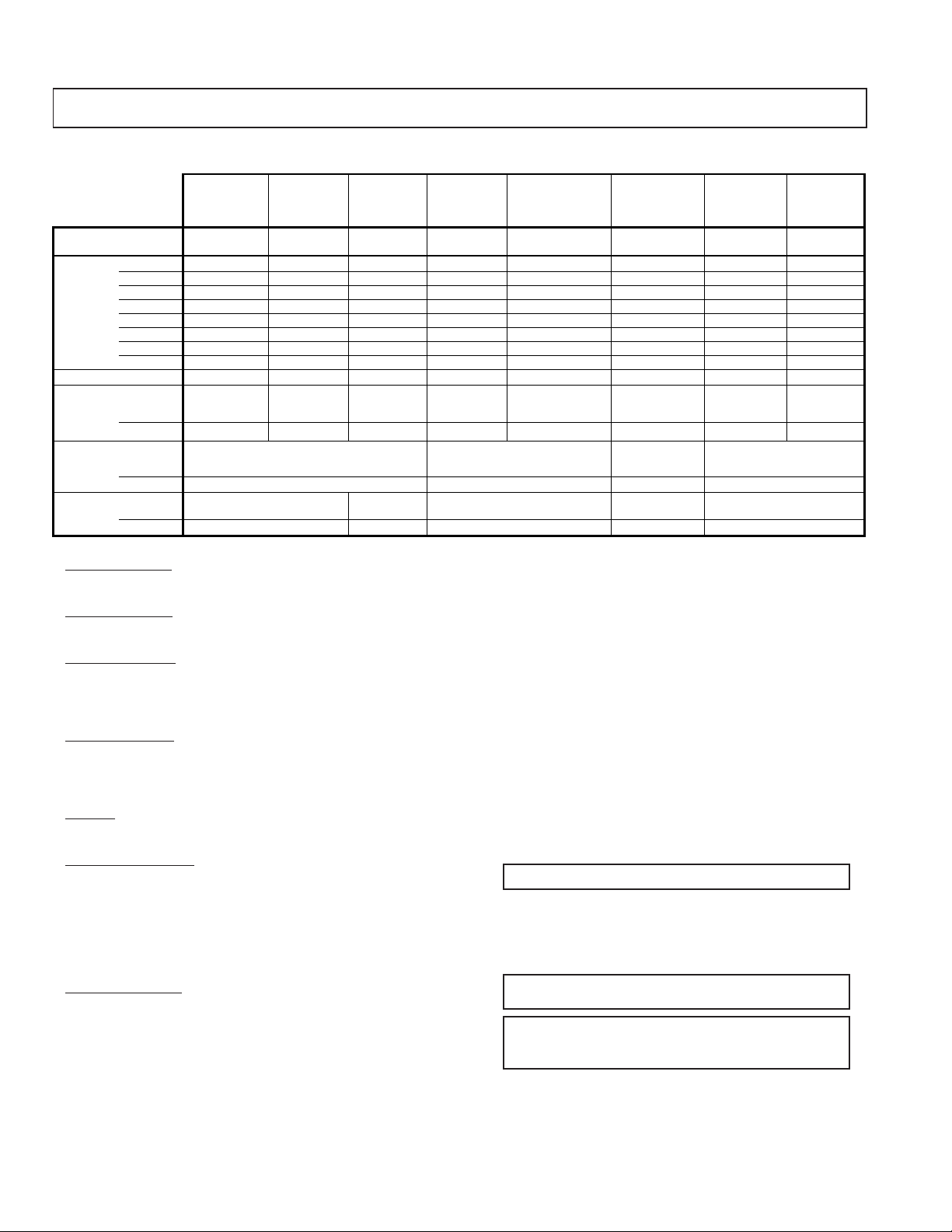
SPECIFICATIONS
KV-32S40 KV-32S45 KV-32V65 KV-35S40/45 KV-35V65
KV-34SL40/40T KV-34SL40C KV-34SL45 KV-32V40 KV-34VL65/65C KV-37SL45 KV-37VL65 KV-37VL65C
Power requirements 120V,60Hz 220V,50/60Hz 120V,60Hz 120V,60Hz 120V,60Hz(65) 120V,60Hz 120V,60Hz 220V,50/60Hz
Number of inputs/outputs
1)
Video
2)
S Video
3)
Audio
Audio Out
1 123 3 2 33
1 111 2 1 22
4)
1 123 3 2 33
1 111 1 1 11
220V,50/60Hz(65C)
Monitor Out ---1 1 - 11
TV out - --- 1 - 11
S-Link - - - - YES - YES YES
Speaker output(W) 5W x 2 5W x 2 5W x 2 5W x 2 10W x 2 5W x 2 10W x 2 10W x 2
Power Consumption(W)
In use(Max)
180W 175W 180W 180W 200W(65), 195W(65C) 210W 230W 225W
In standby 2W 3W 2W 2W 2W(65), 3W(65C) 2W 2W 3W
Dimensions(W/H/D)
(mm)
(in) 31 x 27
Mass
(kg)
(lbs)
Television system
American TV standard
791 x 707 x 604.5mm 821 x 675.3 x 587mm 870 x 761 x 653mm 920 x 730.8 x 641.8mm
13/16
3/4
x 23
71.4kg 72.7kg 70kg 83kg 90kg
157lbs 160lbs 154lbs 183lbs 203lbs
32
3/8
x 26
5/8
x 23
1/8
1)
2)
C: 0.286 Vp-p (Burst signal), 75 ohms
3)
4)
1/4
34
1 Vp-p 75 ohms unbalanced, sync negative
Y: 1 Vp-p 75 ohms unbalanced, sync negative
500 mVrms (100% modulation), Impedance: 47 kilohms
More than 408 mVrms at the maximum volume setting (variable)
x 30 x 25
5/8
36
1/4
x 28
3/4
x 25
1/4
Channel coverage
VHF:2-13/UHF:14-69/CATV:1-125
Visible screen size
32-inch picture measured (KV-32S40/32S45/32V65/34SL40/34SL40C/34SL40T/34SL45/32V40/34VL65/34VL65C)
35-inch picture measured (KV-35S40/35S45/37SL45/35V65/37VL65/37VL65C)
Actual screen size
34-inch picture measured (KV-32S40/32S45/32V65/34SL40/34SL40C/34SL40T/34SL45/32V40/34VL65/34VL65C)
37-inch picture measured (KV-35S40/35S45/37SL45/35V65/37VL65/37VL65C)
Antenna
75 ohm external terminal for VHF/UHF
Supplied Accessories
Remote commander (w/2 size AA (R6) batteries)
RM-Y165: (KV-32S40/32S45/34SL40/34SL40T/34SL40C/35S40/32V40)
(l ) SRS (SOUND RETRIEVAL SYSTEM)
The ( l ) SRS (SOUND RETRIEVAL SYSTEM) is manufactured by Sony Corporation under license from SRS Labs,
RM-Y167: (KV-34SL45/35S45/37SL45/32V65/34VL65/
34VL65C/35V65/37VL65/37VL65C)
Optional Accessory
Connecting Cables: VMC-810S/820S
VMC-720M,YC-15V/30V,RK-74A
TV-Stand: SU-32A3,SU-35A3
VHF/UHF Mixer: EAC-66
Inc. It is covered by U.S. Patent No. 4,748,669. Other U.S.
and foreign patents pending.
The word ‘SRS’ and the SRS symbol (l ) are registered
trademarks of SRS Labs, Inc.
BBE and BBE symbol are trademarks of BBE Sound,Inc.
and are licensed by BBE Sound, Inc. under USP 4638258
and USP 4482866.
Design and specifications are subject to change without notice.
— 2 —
KV-32S40/32S45/34SL40/34SL40C/34SL40T/34SL45/35S40/35S45/37SL45/
TABLE OF CONTENTS
Section Title PageSection Title Page
32V40/32V65/34VL65/34VL65C/35V65/37VL65/37VL65C
1. GENERAL
Connecting and Installing the TV ......................................... 5
Operating Video Equipment................................................... 7
Operating a Cable Box or DBS Receiver............................... 8
Troubleshooting..................................................................... 8
2. DISASSEMBLY
2-1.Rear Cover Removal ...................................................... 9
2-2.Chassis Assembly Removal .......................................... 10
2-3.Service Position ............................................................. 10
2-4.Control Switch Removal ................................................ 10
2-5-1. Picture Tube Removal (32"/34")................................. 11
2-5-2. Picture Tube Removal (35"/37")................................. 11
3. SET-UP ADJUSTMENTS
3-1.Beam Landing................................................................. 12
3-2.Convergence................................................................... 13
3-3.Focus............................................................................... 14
3-4.Screen (G2)..................................................................... 14
3-5.White Balance Adjustments............................................ 14
4. SAFETY RELATED ADJUSTMENTS ................................. 15
5. CIRCUIT ADJUSTMENTS .................................................... 16
6. DIAGRAMS
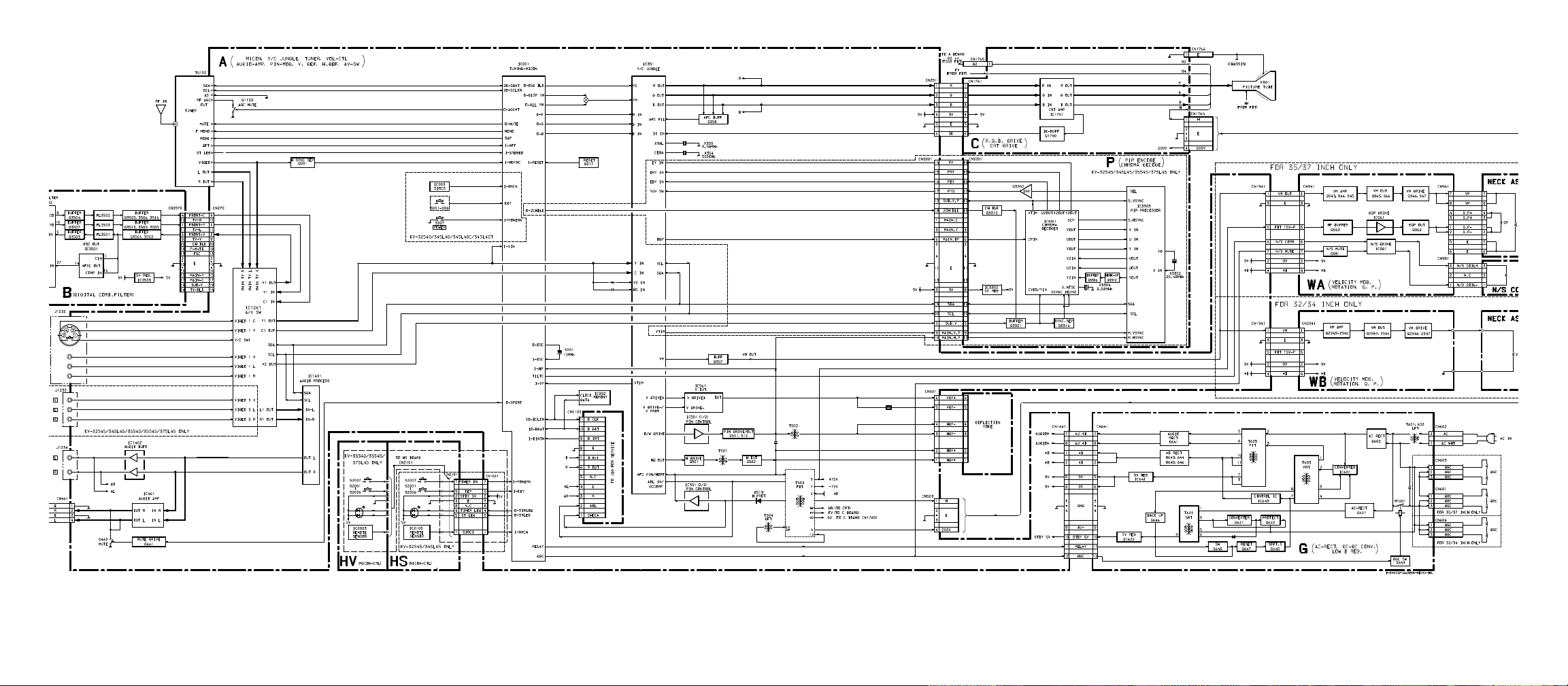
6-1. S Series Block Diagram.................................................. 23
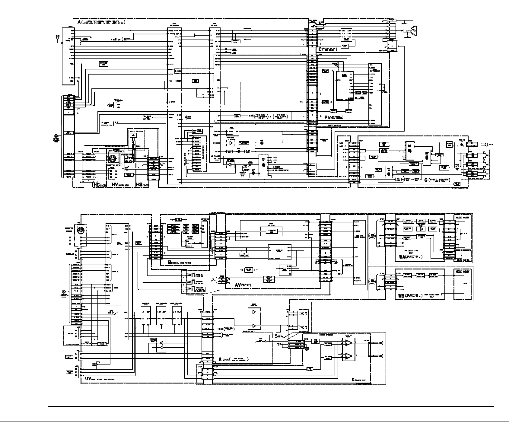
6-2. V Series Block Diagrams ................................................ 27
6-3. Circuit Boards Location................................................... 34
6-4.Printed Wiring Boards and Schematic Diagrams ............ 34
• A Board...................................................................... 35
• AV Board.................................................................... 48
• B Board ..................................................................... 48
• C Board .................................................................... 51
• G Board .................................................................... 52
• HV Board................................................................... 55
• HS Board .................................................................. 55
• K Board...................................................................... 56
• P Board...................................................................... 57
• WB Board.................................................................. 58
• UV Board................................................................... 59
• WA Board................................................................... 63
6-5.Semiconductors.............................................................. 65
7. EXPLODED VlEWS
7-1. Chassis ......................................................................... 66
(KV-32S40/34SL40/34SL40C/32S45/34SL45/34SL40T)
7-2. Chassis.......................................................................... 67
(KV-35S40/35S45/37SL45)
7-3. Chassis.......................................................................... 68
(KV-32V40/32V65/34VL65/35VL65C/
35V65/37VL65/37VL65C)
7-3. Picture Tube .................................................................. 69
(KV-32V40/32V65/34VL65)
7-3. Picture Tube .................................................................. 70
(KV-35VL65C/35V65/37VL65/37VL65C)
8. ELECTRICAL PARTS LIST
• Table of Contents for Parts List.................................. 71
• Parts Listings............................................................. 72
WARNINGS AND CAUTIONS
CAUTION!
AFTER REMOVING THE ANODE, SHORT CIRCUIT THE ANODE
OF THE PICTURE TUBE AND THE ANODE CAP TO THE METAL
CHASSIS, CRT SHIELD, OR CARBON PAINTED ON THE CRT.
WARNING!!
AN ISOLATION TRANSFORMER SHOULD BE USED DURING ANY
SERVICE TO AVOID POSSIBLE SHOCK HAZARD, BECAUSE OF
LIVE CHASSIS.THE CHASSIS OF THIS RECEIVER IS DIRECTLY
CONNECTED TO THE AC POWER LINE.
SAFETY-RELATED COMPONENT WARNING!!
COMPONENTS IDENTIFIED BY SHADING AND MARK ¡ ON
THE SCHEMATIC DIAGRAMS, EXPLODED VIEWS AND IN THE
PARTS LIST ARE CRITICAL FOR SAFE OPERATION. REPLACE
THESE COMPONENTS WITH SONY PARTS WHOSE PART
NUMBERS APPEAR AS SHOWN IN THIS MANUAL OR IN
SUPPLEMENTS PUBLISHED BY SONY. CIRCUIT
ADJUSTMENTS THAT ARE CRITICAL FOR SAFE OPERATION
ARE IDENTIFIED IN THIS MANUAL. FOLLOW THESE
PROCEDURES WHENEVER CRITICAL COMPONENTS ARE
REPLACED OR IMPROPER OPERATION IS SUSPECTED.
ATTENTION
APRES AVOIR DECONNECTE LE CAP DE L'ANODE, COURT-CIRCUITER L'ANODE
DU TUBE CATHODIQUE ET CELUI DE L'ANODE DU CAP AU CHASSIS METALLIQUE
DE L'APPAREIL, OU AU COUCHE DE CARBONE PEINTE SUR LE TUBE CATHODIQUE
OU AU BLINDAGE DU TUBE CATHODIQUE.
ATTENTION!!
AFIN D'EVITER TOUT RESQUE D'ELECTROCUTION PROVENANT D'UN CHÁSSIS
SOUS TENSION, UN TRANSFORMATEUR D'ISOLEMENT DOIT ETRE UTILISÉ LORS
DE TOUT DÉPANNAGE. LE CHÁSSIS DE CE RÉCEPTEUR EST DIRECTEMENT
RACCORDÉ À L'ALIMENTATION SECTEUR.
ATTENTION AUX COMPOSANTS RELATIFS A LA SECURITE!!
LES COMPOSANTS IDENTIFIES PAR UNE TRAME ET PAR UNE MARQUE ¡ SUR
LES SCHEMAS DE PRINCIPE, LES VUES EXPLOSEES ET LES LISTES DE PIECES
SONT D'UNEIMPORT ANCE CRITIQUE POUR LA SECURITE DU FONCTIONNEMENT.
NE LES REMPLACER QUE PAR DES COMPOSANTS SONY DONT LE NUMERO DE
PIECE EST INDIQUE DANS LE PRESENT MANUEL OU DANS DES SUPPLEMENTS
PUBLIES PAR SONY. LES REGLAGES DE CIRCUIT DONT L'IMPORT ANCE EST CRITIQUE POUR LA SECURITE DU FONCTIONNEMENT SONT IDENTIFIES DANS LE
PRESENT MANUEL. SUIVRE CES PROCEDURES LORS DE CHAQUE
REMPLACEMENT DE COMPOSANTS CRITIQUES, OU LORSQU'UN MAUVAIS
FONTIONNEMENT SUSPECTE.
— 3 —
— 5 —
3
Using This Manual
Precautions
Welcome!
Thank you for purchasing the Sony
Trinitron
®
Color TV. This manual is written
for the models listed below. Before reading,
check the model number located on the front
of this manual or on the rear of your TV.
Model KV-35S45 is used for menu and
illustration purposes. Differences in
operation are indicated in the text; for
example, “KV-35S45 only”.
This manual is divided into four major
sections. We recommend that you carefully
review the contents of each section in the
order presented to ensure that you fully
understand the operation of your new TV.
1 Connecting and Installing the TV
This section guides you through your
initial set up. It shows how to connect to
your antenna or cable, and connect any
accessories or components.
2 Basic Set Up
This section teaches you the basic skills
needed to operate your new TV. It shows
you how to operate special functions of
the remote control.
3 Using your New TV
This section shows you how to begin
using your new TV. It shows how to use
the Easy Set Up Guide feature, and how to
use your remote control.
4 Using your Menus
This section teaches you how to access
on-screen menus and adjust your TV's
settings.
Instructions in this manual are written for the
remote control. Similar controls may be found on
the TV console.
Safety
• Operate the TV only with 120 V AC .
• The plug is designed, for safety purposes,
to fit in the wall outlet only one way. If
you are unable to insert the plug fully into
the outlet, contact your dealer.
• If any liquid or solid object should fall
inside the cabinet, unplug the TV
immediately and have it checked by
qualified personnel before operating it
further.
• If you will not be using the TV for several
days, disconnect power by pulling the
plug itself. Never pull on the cord.
For details concerning safety precautions, see the
supplied leaflet “IMPORTANT SAFEGUARDS”.
Installing
• To prevent internal heat build-up, do not
block the ventilation openings.
• Do not install the TV in a hot or humid
place, or in a place subject to excessive
dust or mechanical vibration.
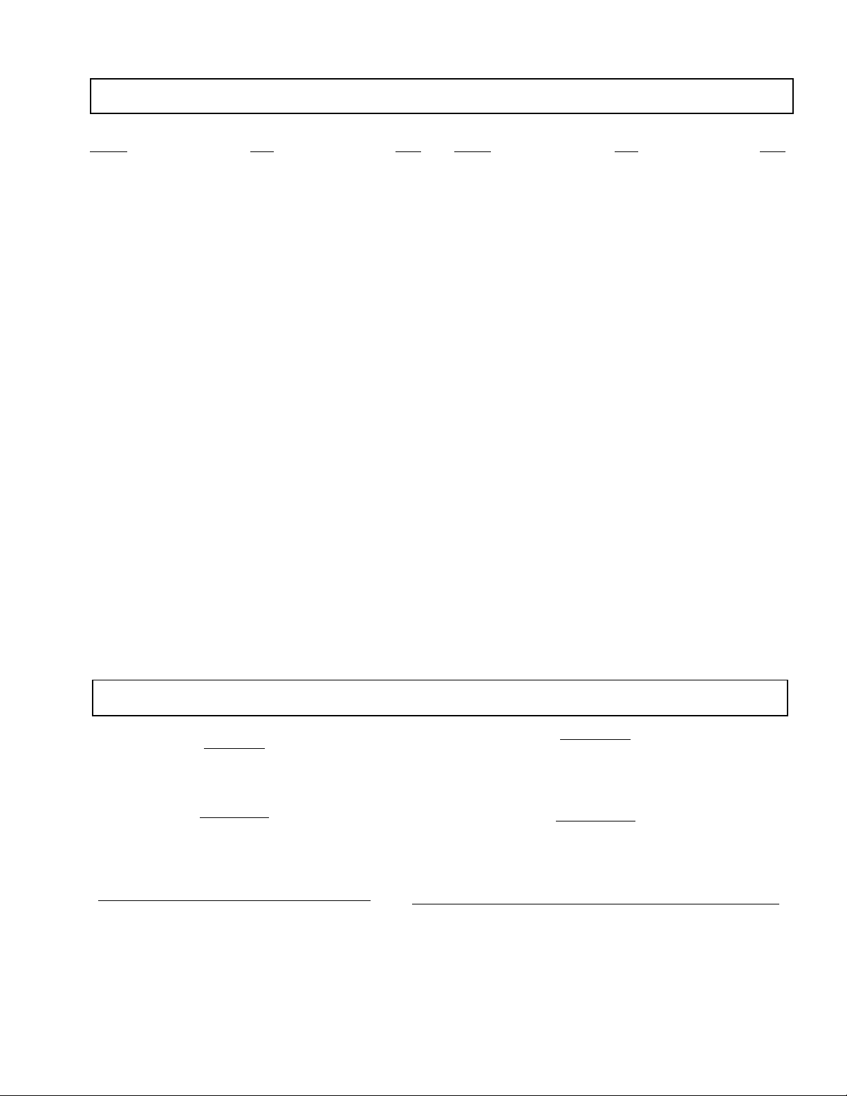
Model
Number
Single tuner
(VCR required for PIP)
Dual tuner
("Ready to Use" PIP)
SRS
FAVORITE CHANNEL
with Preview
KV-32S40
KV-32S45
KV-32S65
KV-32V40
KV-32V65
KV-35S40
KV-35S45
KV-35S65
KV-35V65
AUTO VOLUME
Control
SURROUND
4
Cable or antenna only 5
Cable and antenna (KV-32S65, 32V65, 35S65, 35V65 only) 5
Cable box 6
Cable box and cable to view scrambled channels (KV-32S65, 32V65, 35S65,
35V65 only) 6
V
CR and cable or antenna 7
VCR and cable box 7
Direct Broadcast Satellite Receiver (DBS) 8
VCR and Direct Broadcast Satellite Receiver (DBS) 8
Digital Versatile Disc player (DVD) 9
Audio system 9
A/V receiver 10
Two VCR's for tape editing (KV-32V40, 32V65, 35V65 only) 10
Camcorder to view tapes 11
S-Link connections (KV-32S65, 32V65, 35S65, 35V65 only) 12
Making Connections
Connecting and Installing the TV
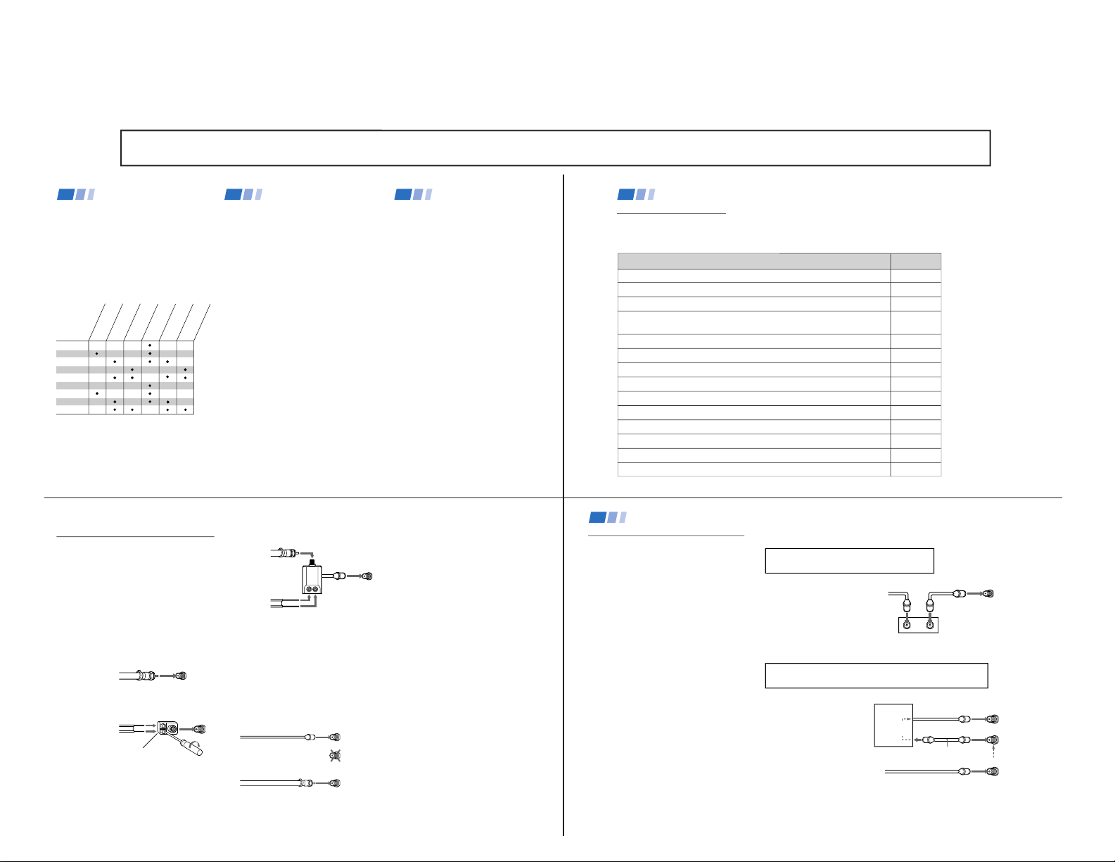
Refer to the table below, it will direct you to the diagram suitable to the components you will be
connecting.
If you will be connecting See page
5
B
• VHF only
or
• UHF only
or
• VHF/UHF
C
• VHF
and
• UHF
Cable or Antenna Connections
Connecting directly to cable or an
antenna
The connection you choose will depend on the
cable found in your home. Newer homes will
be equipped with standard coaxial cable
(see
A); older homes will probably have
300-ohm twin lead cable (see
B); still other
homes may contain both (see
C).
A
• VHF only
or
• VHF/UHF
or
• Cable
Antenna connector
(Rear of TV)
VHF/UHF
300-ohm twin
lead cable
(Rear of TV)
VHF/UHF
75-ohm
coaxial cable
75-ohm coaxial cable
300-ohm twin lead cable
(Rear of TV)
VHF/UHF
EAC-66 U/V mixer
(not supplied)
(No connection "TO
CONVERTER" in this case)
CATV cable
Antenna cable
TO CONVERTER
VHF/UHF
(Rear of TV)
AUX
Cable and antenna
• KV-32S65, 32V65, 35S65, 35V65 only
If your cable provider does not feature local
channels, you may find this set up convenient
for viewing both local and cable channels.
Select cable or antenna mode by pressing
ANT on the remote control. You will be able
to alternate between the two input sources.
Note
• In order to receive channels with an
antenna, you will need to turn your CABLE
to OFF (see page 26) and perform the
AUTO PROGRAM function.
6
Connecting and Installing the TV (continued)
Cable Box Connections
Some pay cable TV systems use scrambled or
encoded signals that require a cable box to
view all channels.
Cable box
1 Connect the coaxial connector from your
cable to the IN on your cable box.
2 Using a coaxial cable, connect OUT on
your cable box to VHF/UHF on your TV.
Cable box and cable
• KV-32S65, 32V65, 35S65, 35V65 only
For this set up, you can switch between
scrambled channels (through your cable box),
and normal (CATV) channels by pressing
ANT on your remote control.
Notes
• Your Sony remote control can be
programmed to operate your cable box.
(see page 32)
• When using PIP, you cannot view the
AUX input in the window picture.
Tip z
Pressing ANT switches between these inputs.
Cable box
Cable
OUTIN
(Rear of TV)
VHF/UHF
TO CONVERTER
Cable box
VHF/UHF
(Rear of TV)
AUX
75-ohm coaxial
cable (not supplied)
CATV cable
(unscrambled channels)
(signal)
scrambled
channels
If you will be controlling all channel selection
through your cable box, you should consider using
the CHANNEL FIX feature discussed on page 26.
If you are connecting a cable box through the AUX input and would
like to switch between the AUX and normal (CATV) input you should
consider using the CHANNEL FIX feature discussed on page 26.
SECTION 1 GENERAL
The instructions mentioned here are partial abstracts from the Operating Instruction Manual. The page numbers shown reflect those of the Operating Instruction Manual.
KV-32S40/32S45/34SL40/34SL40C/34SL40T/34SL45/35S40/35S45/37SL45/
32V40/32V65/34VL65/34VL65C/35V65/37VL65/37VL65C
— 6 —
7
AUDIO R AUDIO L VIDEO
S VIDEO
LINE
OUT
OUT
IN
OUT
IN
AUDIO OUT
(
VAR/FIX
)
VIDEO
IN
12
VHF/UHF
S VIDEO
VIDEO
L
R
AUDIO
(
MONO
)
L
R
Disconnect all power sources before making any connections.
VCR must be connected and
turned on to operate PIP
(KV-32S45, 35S45 only).
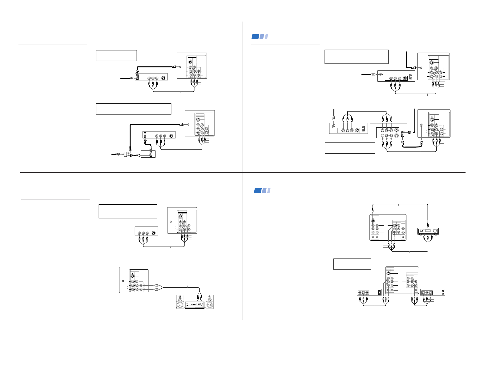
VCR Connections
Connecting an antenna/cable TV
system with a VCR
1 Attach the coaxial connector from your cable
or antenna to IN on your VCR.
2 Using A/V connectors, connect AUDIO and
VIDEO OUT on your VCR to AUDIO and
VIDEO IN on your TV.*
3 Using a coaxial connector, connect OUT on
your VCR to VHF/UHF on your TV.
* If you are connecting a monaural VCR, connect only the
single white audio output to the left input on your TV.
Connecting a VCR and TV with a
cable box
You will need a splitter (not supplied) for the
following connection.
1 Connect the single (input) jack of the splitter
to your incoming cable connection. Connect
the other two (output) jacks (using coaxial
cable) to IN on your cable box and VHF/UHF
on your TV.
2 Using a coaxial connector, connect OUT on
your cable box to IN on your VCR.
3 Using A/V connectors, connect AUDIO and
VIDEO OUT on your VCR to AUDIO and
VIDEO IN on your TV.
Coaxial cable
(Rear of TV)
VMC-810S/820S (not supplied)
Cable
VCR
3
1
2
AUDIO-R (red)
AUDIO-L (white)
VIDEO (yellow)
VMC-810S/820S (not supplied)
Cable box
Splitter
(not supplied)
3
AUDIO-R (red)
AUDIO-L (white)
VIDEO (yellow)
VCR
Cable
Coaxial cable
2
1
For optimum picture quality, use S VIDEO instead of
the yellow A/V cable. S Video does not provide sound,
your audio connectors must still be connected.
(Rear of TV)
AUDIO OUT
(
VAR/FIX
)
VIDEO
IN
12
VHF/UHF
S VIDEO
VIDEO
L
R
AUDIO
(
MONO
)
AUDIO R AUDIO L VIDEO
S VIDEO
LINE
OUT
OUT
IN
L
R
8
AUDIO R AUDIO L VIDEO
AUDIO R AUDIO L VIDEO
SATELLITE IN
VHF/UHF
S VIDEO
OUT
IN
LINE OUT
LINE IN
VHF/UHF
S VIDEO
OUT
IN
LINE OUT
AUDIO OUT
(
VAR/FIX
)
VIDEO
IN
12
VHF/UHF
S VIDEO
VIDEO
L
R
AUDIO
(
MONO
)
L
R
Disconnect all power sources before making any connections.
DBS receiver
Satellite
antenna
cable
VMC-810S/820S (not supplied)
1
3
2
AUDIO-R (red)
AUDIO-L (white)
VIDEO (yellow)
Connecting and Installing the TV (continued)
For optimum picture quality, use S VIDEO
instead of the yellow A/V cable. S Video does
not provide sound, your audio connectors
must still be connected.
DBS Connections
Connecting a DBS (Direct
Broadcast Satellite) receiver
1 Connect the cable from your satellite
antenna to your DBS receiver.
2 Attach the coaxial connector from your
cable or antenna to VHF/UHF on your TV.
3 Using A/V connectors, connect AUDIO
and VIDEO OUT on your DBS receiver to
AUDIO and VIDEO IN on your TV.
Connecting a DBS (Direct Broadcast
Satellite) receiver and a VCR
1 Connect the cable from your satellite
antenna to your DBS receiver.
2 Attach the coaxial connector from your
cable or antenna to VHF/UHF IN on your
VCR.
3 Using a coaxial connector, connect
VHF/UHF OUT on your VCR to
VHF/UHF on your TV.
4 Using A/V connectors, connect AUDIO
and VIDEO OUT on your DBS receiver to
AUDIO and VIDEO IN on your VCR.
5 Using A/V connectors, connect AUDIO
and VIDEO OUT on your VCR to AUDIO
and VIDEO IN on your TV.
(Rear of TV)
AUDIO-R (red)
AUDIO-L (white)
VIDEO (yellow)
1
2
3
VMC-810S/820S (not supplied)
VMC-810S/820S (not supplied)
4
5
(Rear of TV)
DBS receiver
VCR
Pressing TV/VIDEO on the remote
control will allow you to view from
the DBS or VCR.
VHF/UHF
S VIDEO
OUT
IN
LINE OUT
SATELLITE IN
AUDIO R AUDIO L VIDEO
AUDIO OUT
(
VAR/FIX
)
VIDEO
IN
12
VHF/UHF
S VIDEO
VIDEO
L
R
AUDIO
(
MONO
)
L
R
Cable/Antenna
Cable/Antenna
9
Additional Connections
The following connections are for accessories
that will enhance your viewing options.
Connecting a DVD Player
1 Using A/V connectors, connect LINE OUT
on your DVD to VIDEO IN on your TV.
Connecting an audio system
For enhanced sound, connect your audio
system to your TV.
1 Using AUDIO connectors, connect AUDIO
OUT on your TV to one of the unused line
inputs (e.g. TV, AUX, TAPE 2) on your
stereo.
2 Set your stereo to the chosen line input.
Refer to page 24 of this manual for
additional audio setup instructions.
VMC-810S/820S (not supplied)
1
(Rear of DVD player)
AUDIO-R (red)
AUDIO-L (white)
VIDEO (yellow)
Line
input
AUDIO-R (red)
AUDIO-L (white)
RK-74A
(not supplied)
1
2
Disconnect all power sources before making any connections.
For optimum picture quality, use S VIDEO
instead of the yellow A/V cable. S Video
does not provide sound, your audio
connectors must still be connected.
(Rear of TV)
(Rear of TV)
AUDIO OUT
(
VAR/FIX
)
VIDEO
IN
12
VHF/UHF
S VIDEO
VIDEO
L
R
AUDIO
(
MONO
)
HRD
AUDIO R AUDIO L VIDEO
S VIDEO
LINE OUT
AUDIO OUT
(
VAR/FIX
)
VIDEO
IN
12
VHF/UHF
S VIDEO
VIDEO
L
R
AUDIO
(
MONO
)
L
R
10
HRD
L
R
AUDIO
(
MONO
)
S VIDEO
VIDEO
IN
VIDEO 1
VIDEO 3
TV MONITOR
AUDIO
(VAR/FIX)
OUT
S-LINK
L
R
AUDIO
(
MONO
)
S VIDEO
VIDEO
IN
VIDEO 1
VIDEO 3
TV MONITOR
AUDIO
(VAR/FIX)
OUT
S-LINK
LINE
OUT
OUT
IN
LINE
IN
OUT
IN
AUDIO R AUDIO L VIDEO AUDIO R AUDIO L VIDEO
Disconnect all power sources before making any connections.
Connecting an A/V receiver
• KV-32V65, 35V65 only
1 Using A/V cables, connect TV OUT on your
TV to TV IN on your A/V receiver.
2 Using a single video connector, connect
Monitor OUT on your A/V receiver to
VIDEO 1 IN on your TV.
Tip
z
You may want to use CHANNEL FIX to set your TV's
input to the A/V receiver. See page 26.
Connecting two VCRs
• KV-32V40, 32V65, 35V65 only
MONITOR OUT gives you the ability to use a
second VCR to record a program being played
by the primary VCR or to perform tape
editing and dubbing.
1 Connect the VCR intended for playback
using the setup instructions on page 7 of
this manual.
2 Using A/V connectors, connect AUDIO
and VIDEO IN on your VCR intended for
recording to MONITOR AUDIO and
VIDEO OUT on your TV.
VCR (for playback)
VCR (for recording)
VMC-810S/820S (not supplied)
VMC-810S/820S (not supplied)
(Rear of KV-35V65)
VIDEO (yellow)
AUDIO-L (white)
AUDIO-R (red)
1
2
You cannot change video
inputs while editing using
MONITOR OUT.
(Rear of KV-35V65)
VMC-10HG/30HG (not supplied)
VIDEO (yellow)
VIDEO (yellow)
AUDIO-L (white)
AUDIO-R (red)
VMC-810S/820S (not supplied)
A/V inputs
A/V receiver
A/V outputs
2
1
Connecting and Installing the TV (continued)
KV-32S40/32S45/34SL40/34SL40C/34SL40T/34SL45/35S40/35S45/37SL45/
32V40/32V65/34VL65/34VL65C/35V65/37VL65/37VL65C
— 7 —
11
VIDEO 2 INPUT
L
(
MONO
)
-
AUDIO
-RVIDEO
VIDEO 2 INPUT
VIDEO
L
(
MONO
)
-
AUDIO
-
R
S VIDEO
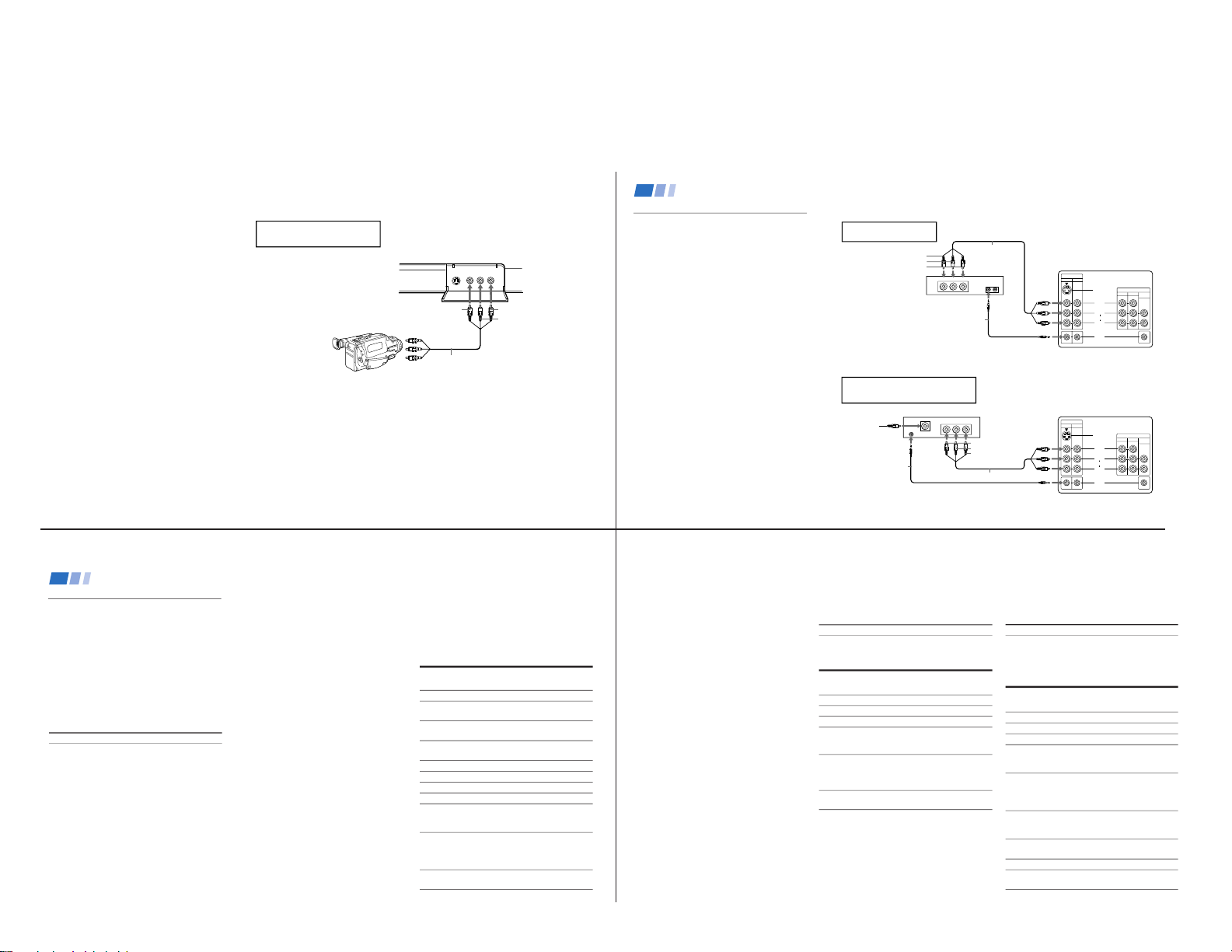
Connecting a camcorder
This connection is convenient for viewing a
picture directly from your camcorder.
Using A/V connectors, connect AUDIO and
VIDEO OUT on your camcorder to AUDIO
and VIDEO IN on your TV.
Connection can also be made directly to your
A/V input located on the rear of your TV.
Note
•
If you are connecting a monaural camcorder,
connect only the single white audio output
to the left input on your TV.
If you have an S VIDEO equipped
camcorder, you can use an S Video
cable for optimum picture quality.
AUDIO-L (white)
AUDIO-R (red)
VIDEO (yellow)
AV output
VMC-810S/820S
(not supplied)
(Front of KV-32V40*, 32V65, 35V65 only)
Disconnect all power sources before making any connections.
* KV-32V40 does not have S VIDEO on the front panel.
12
Connect to the CONTROL
S-IN on your VCR.
LINE
OUT
AUDIO R AUDIO L VIDEO
S-LINK
L
R
AUDIO
(
MONO
)
S VIDEO
VIDEO
IN
VIDEO 1
VIDEO 3
TV MONITOR
AUDIO
(VAR/FIX)
OUT
S-LINK
SATELLITE IN
LINE
OUT
OUTIN
AUDIO R AUDIO L VIDEO
S-LINK
CONTROL S
L
R
AUDIO
(
MONO
)
S VIDEO
VIDEO
IN
VIDEO 1
VIDEO 3
TV MONITOR
AUDIO
(VAR/FIX)
OUT
S-LINK
Disconnect all power sources before making any connections.
S-Link connections
• KV-32S65, 32V65, 35S65, 35V65 only
S-Link is designed to allow your Sony
components to ”communicate“.
Connecting S-Link to a VCR
S-Link will automatically power on the TV
and switch to the correct video input when a
tape is inserted in the VCR.
1 Using A/V connectors, connect AUDIO
and VIDEO OUT on your VCR to AUDIO
and VIDEO IN on your TV.
2 Using an S-Link connector (mono mini
plug), connect S-LINK/CONTROL S-IN on
your VCR to S-LINK on your TV.
Connecting S-Link to a DBS
S-Link will automatically power on the TV
and switch to the correct video input when
you power on the DBS.
1 Using A/V connectors, connect AUDIO
and VIDEO OUT on your DBS to AUDIO
and VIDEO IN on your TV.
2 Using an S-Link connector (mono mini
plug), connect S-LINK on your DBS to
S-LINK on your TV.
VCR
RK-G69HG
(not supplied)
(Rear of KV-35V65)
AUDIO-R (red)
AUDIO-L (white)
VIDEO (yellow)
1
2
VMC-810S/820S
(not supplied)
(Rear of KV-35V65)
RK-G69HG
(not supplied)
VMC-810S/820S (not supplied)
Satellite
Antenna
Cable
DBS Receiver
21
AUDIO-R (red)
AUDIO-L (white)
VIDEO (yellow)
Connecting and Installing the TV (continued)
The S-Link connector must be in the
same VIDEO-IN jacks as the A/V cables
on your TV.
30
Programming the remote
You can use the supplied remote control to
operate Sony or non-Sony video equipment.
Operating Video Equipment
1 Press CODE SET.
2 Press VTR/DVD (FUNCTION).
3 Use the 0-9 buttons to key in the
manufacturer's code number from the
following chart.
4 Press ENTER.
VCR code numbers
Manufacturer Code
Sony 301, 302, 303
Admiral (M. Ward) 327
Aiwa 338, 344
Audio Dynamic 314, 337
Broksonic 319, 317
Canon 309, 308
Citizen 332
Craig 302, 332
Criterion 315
Curtis Mathis 304, 338, 309
Daewoo 341, 312, 309
DBX 314, 336, 337
Dimensia 304
Emerson 319, 320, 316, 317, 318, 341
Fisher 330, 335
Funai 338
General Electric 329, 304, 309
Go Video 322, 339, 340
Goldstar 332
Hitachi 306, 304, 305,338
Instant Replay 309, 308
JC Penney 309, 305, 304, 330, 314, 336, 337
JVC 314, 336, 337, 345, 346, 347
Kenwood 314, 336, 332, 337
LXI (Sears) 332, 305, 330, 335, 338
Magnavox 308, 309, 310
Marantz 314, 336, 337
Marta 332
Memorex 309, 335
Minolta 305, 304
Mitsubishi/MGA 323, 324, 325, 326
Multitech 325, 338, 321
NEC 314, 336, 337
Olympic 309, 308
Optimus 327
Panasonic 308, 309, 306, 307
Pentax 305, 304
Philco 308, 309
Philips 308, 309, 310
Pioneer 308
Quasar 308, 309, 306
RCA/PROSCAN 304, 305, 308, 309, 311,
312, 313, 310, 329
Realistic 309, 330, 328, 335, 324, 338
Sansui 314
Samsung 322, 313, 321
Sanyo 330, 335
Scott 312, 313, 321, 335, 323, 324, 325, 326
Sharp 327, 328
Shintom 315
Signature 2000 (M. Ward) 338, 327
SV2000 338
Sylvania 308, 309, 338, 310
Symphonic 338
Tashiro 332
Tatung 314, 336, 337
Teac 314. 336, 338, 337
Technics 309, 308
Toshiba 312, 311
Wards 327, 328, 335, 331, 332
Yamaha 314, 330, 336, 337
Zenith 331
Operating a VCR
To turn on or off
To select a channel
directly
To change
channels
To record
To play
To stop
To fast forward
To rewind the tape
To pause
To scan
To change input
mode
Buttons on the
remote control
Press VTR/DVD (POWER).
Press the 0 – 9 buttons.
Press CH +/–.
Press ( and r
simultaneously.
Press (.
Press p.
Press ).
Press 0.
Press P.
To resume normal playback,
press again or press (.
Press ) or 0 during
playback.
To resume normal playback,
release the button.
Press TV/VTR.
31
MDP (Multi Disc Player)
code numbers
Manufacturer Code
Sony 701
Panasonic 704, 710
Pioneer 702
Operating an MDP
To turn on or off
To play
To stop
To pause
To scan
To search the chapter
forward or backward
Tip z
If you will not be programming a DBS or cable box into
the DBS/CABLE input, you can use it to program other
video equipment (e.g. DVD, MDP, or second VCR).
(see page 30)
DVD (Digital Versatile Disc)
code numbers
Manufacturer Code
Sony 751
Panasonic 753
Pioneer 752
RCA 755
Toshiba 754
Operating a DVD
player
To turn on or off
To play
To stop
To pause
To scan
To search the
chapter forward or
backward
To select chapters
directly
MENU
To move cursor in
menu
Buttons on the remote
control
Press VTR/DVD (POWER).
Press (.
Press p.
Press P.
To resume normal playback,
press again or press (.
Press ) or 0 during
playback.
To resume normal playback,
press (.
Press CH +/–.
0–9 + ENTER.
Press to display DVD menu.
Use your arrow buttons
V, v, B, b.
Buttons on the remote
control
Press VTR/DVD (POWER).
Press (.
Press p.
Press P.
To resume normal playback,
press again or press (.
Press ) or 0 during
playback.
To resume normal playback,
press (.
Press CH +/–.
Tips z
• In some rare cases, you may not be able to operate
your non-Sony video equipment with the supplied
remote control. In this case, please use the
equipment’s own remote control.
• When you remove the batteries, the code number may
revert to the factory setting.
• The code numbers for Sony VCR's are assigned at the
factory as follows:
VHS VCR 301
(preset code for the
supplied remote control)
8 mm VCR 302
Beta, ED Beta VCRs 303
KV-32S40/32S45/34SL40/34SL40C/34SL40T/34SL45/35S40/35S45/37SL45/
32V40/32V65/34VL65/34VL65C/35V65/37VL65/37VL65C
— 8 —
32
Manufacturer
Hamlin/Regal
Jerrold/G. I.
Oak
Panasonic
Pioneer
Scientific Atlanta
Tocom
Zenith
Programming the remote
You can program the supplied remote control
to operate a cable box or DBS receiver.
1 Press CODE SET.
2 Press DBS/CABLE (FUNCTION).
3 Use the 0-9 buttons to key in the
manufacturer's code number from the
following chart.
4 Press ENTER.
For more details on operating the
cable box or DBS receiver
Refer to the operating instructions that were
supplied with the equipment.
If the remote control doesn’t work
• First, try repeating the setup procedures
using the other codes listed for your
equipment.
Tips z
• If more than one code number is listed, try entering
them one by one until you come to the correct code for
your equipment.
• If you enter a new code number, the code number you
previously entered at that setting is erased.
•
In some rare cases, you may not be able to operate
your equipment with the supplied remote control. In
this case, use the equipment’s supplied remote control.
• Whenever you remove the batteries the code numbers
may revert to the factory setting.
Cable box code numbers
Code
222, 223, 224, 225, 226
201, 202, 203, 204, 205, 206,
207, 208, 218
227, 228, 229
219, 220, 221
214, 215
209, 210, 211
216, 217
212, 213
DBS receiver code numbers
Manufacturer
Sony
General Electric
Hitachi
Hughes
Panasonic
RCA/PROSCAN
Toshiba
Code
801 (preset code for
remote control)
802
805
804
803
802, 808
806, 807
Operating a Cable Box or DBS Receiver
33
Problem What it could be What you can do
Cannot operate single tuner PIP
(KV-32S45, 35S45)
A red light keeps flashing on the
TV for more than a few seconds
TV makes a noise when turned
on
Screen is not lit and there is no
sound
Poor or no picture (screen lit),
good sound
Good picture, no sound
No color
Troubleshooting
Consult the table below; it suggests solutions to specific problems.
• VCR may not be connected to your TV properly.
• VCR may not be turned on.
• The remote control may not be programmed to
operate the VCR.
• Your TV may need service.
• This is a normal function of your TV.
• Power cord may not be plugged in.
• Batteries may not have been placed with the correct
polarity.
• TV/VIDEO setting may be incorrect.
• VIDEO menu settings may not be adjusted correctly.
• Antenna/cable connections may be faulty.
• VIDEO LABEL inputs may be set to WEB. (This label
darkens the screen for ideal WebTV viewing)
• Sound may be set to MUTING.
• Your TV may be set to SAP.
• Speaker may not be set correctly.
• Color settings may not be adjusted correctly.
•
Ensure that you have set your VCR correctly. (see page 7)
• Program your remote control to operate the VCR.
(see page 30)
• Call your local Sony service center.
• Press TV/VIDEO until you receive a channel.
• Readjust your VIDEO menu settings.(see page 22)
• Check your VIDEO LABEL settings. (see page 28)
• Press MUTE.
•
Check the MTS setting in the AUDIO menu. (see page 23)
• Check your SPEAKER settings. (see page 23)
• Adjust the COLOR settings in the VIDEO menu.
(see page 22)
34
Problem What it could be What you can do
If, after reading these operating instructions, you have additional questions related to the use of your Sony
television, please call our Direct Response Center at 1-800-222-SONY (7669). (U.S. residents only)
• Ensure that you have selected the
correct CABLE mode in the
SET UP menu. (see page 26)
• Press ANT on your remote
control to change the input mode.
(see page 16)
•
Ensure that CABLE is set to OFF
in the SET UP menu. (see page 26)
• Use AUTO PROGRAM to add
receivable channels that are not
presently in TV memory. (see
page 26)
• Ensure that CABLE is set to ON
in the SET UP menu. (see page 26)
• Use AUTO PROGRAM to add
receivable channels that are not
presently in TV memory. (see
page 26)
• Press TV (FUNCTION) and
adjust the TV's volume.
• Check your CHANNEL FIX
settings. (see page 26)
• CABLE may not be set correctly
in the SET UP menu.
• Antenna/cable connections may
not be correct.
• TV may be set to AUX mode.
• CABLE setting may not be correct
in the SET UP menu.
• CABLE setting may not be set
correctly in the SET UP menu.
• Volume may not be adjusted on
your cable box.
• CHANNEL FIX settings may not
be correct.
Only snow and noise
appear on the screen
Cannot receive upper
channels (UHF) when
using an antenna
Cannot receive any
channels when using
cable
Cannot gain enough
volume when using a
cable box
TV is fixed to one
channel
KV-32S40/32S45/34SL40/34SL40C/34SL40T/34SL45/35S40/35S45/37SL45/
32V40/32V65/34VL65/34VL65C/35V65/37VL65/37VL65C
KV-32S40/32S45/34SL40/34SL40C/34SL40T/34SL45/35S40/35S45/37SL45/
32V40/32V65/34VL65/34VL65C/35V65/37VL65/37VL65C
SECTION 2
DISASSEMBLY
2-1. REAR COVER REMOVAL
(KV-32S40/34SL40/34SL40C/32S45/34SL45/34SL40T/ (KV-35S40/35S45/37SL45/37VL65/37VL65C)
32V40/32V65/34VL65/34VL65C)
1 1
1 Eleven Screws
1 1
1 Eleven Screws
1 1
(BVTP 4x16)
1 1
(BVTP 4x16)
2 2
2 Two Screws
2 2
(BVTP 3x12)
2 2
2 Two Screws
2 2
2-2. CHASSIS ASSEMBLY REMOVAL
(KV-32S40/34SL40/34SL40C/32S45/ (KV-32V40/32V65/34VL65/34VL65C/35V65/
34SL45/35S40/35S45/37SL45/34SL40T) 37VL65/37VL65C)
1 1
1 Claw
1 1
1 1
1 Claw
1 1
3 3
3 G Board
3 3
(BVTP 4x16)
4 4
4 G Board
4 4
2 2
2 Chassis Assembly
2 2
— 9 —
2 2
2 K Board
2 2
3 3
3 Chassis Assembly
3 3
KV-32S40/32S45/34SL40/34SL40C/34SL40T/34SL45/35S40/35S45/37SL45/
32V40/32V65/34VL65/34VL65C/35V65/37VL65/37VL65C
2-3. SERVICE POSITION
1 1
1 A Board
1 1
2 2
2 G Board
2 2
2-4. CONTROL SWITCH REMOVAL
(KV-32V65/34VL65/34VL65C/35VL65/35VL65C/37VL65C)
1 1
1 Control Switch
1 1
2 2
2 Four Claws
2 2
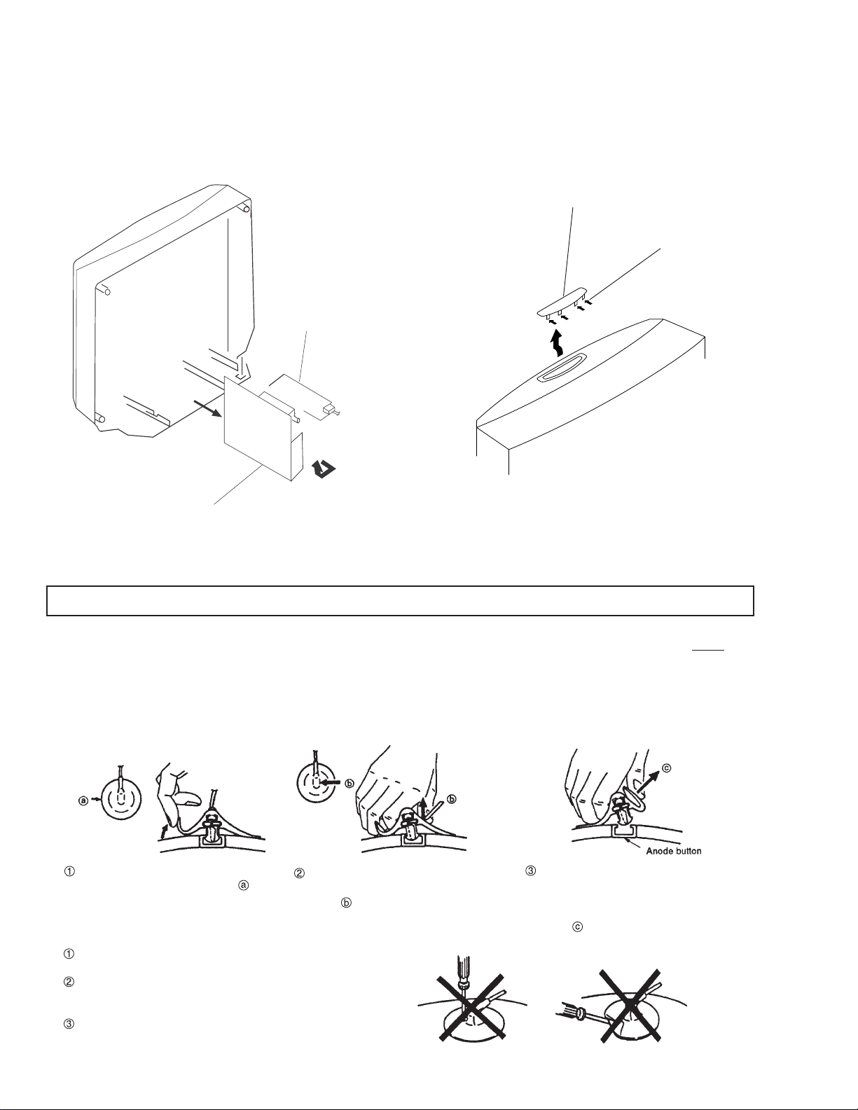
ANODE-CAP REMOVAL
WARNING:
NOTE: After removing the anode, short circuit the anode of the picture tube and the anode cap to either the metal chassis, CRT shield
High voltage remains in the CRT even after the power is disconnected. To avoid electrical shock, discharge CRT before
attempting to remove the anode cap. Short between anode and coated earth ground strap of CRT.
or carbon painted on the CRT.
REMOVAL PROCEDURES
Turn up one side of the rubber cap in
the direction indicated by arrow .
Use your thumb to pull the rubber cap
firmly in the direction indicated by
arrow .
HOW TO HANDLE AN ANODE-CAP
Do not use sharp objects which may cause damage to the sur-
face of the anode-cap.
Do not squeeze the rubber covering too hard to avoid damag-
ing the anode-cap. A material fitting called a shatter-hook terminal is built into the rubber.
Do not force turn the foot of the rubber cover. This may cause
the shatter-hook terminal to protrude and damage the rubber.
When one side of the rubber cap sepa-
rates from the anode button, the anodecap can be removed by turning the rubber cap and pulling it in the direction of
arrow .
— 10 —
KV-32S40/32S45/34SL40/34SL40C/34SL40T/34SL45/35S40/35S45/37SL45/
32V40/32V65/34VL65/34VL65C/35V65/37VL65/37VL65C
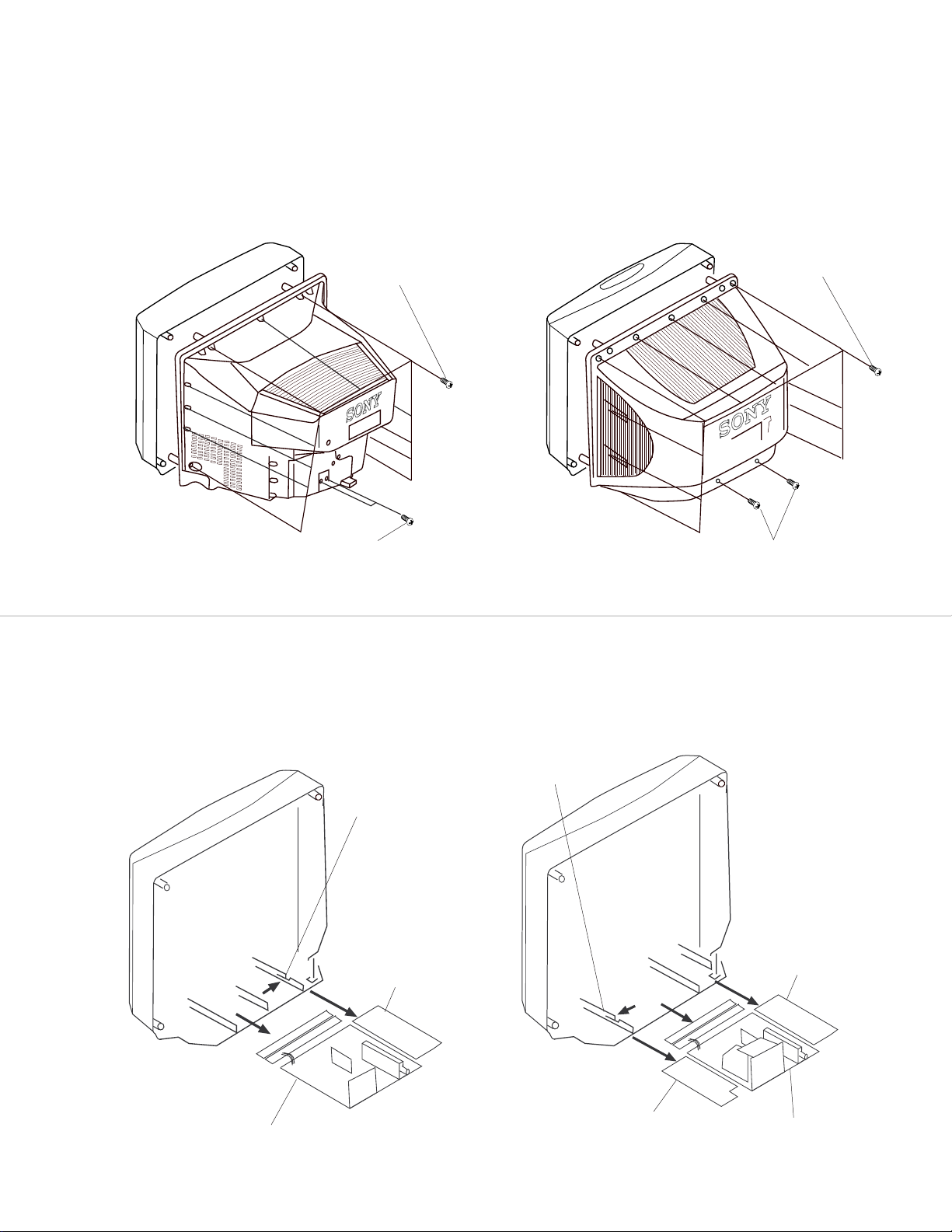
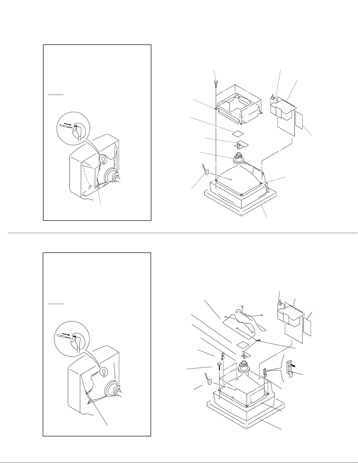
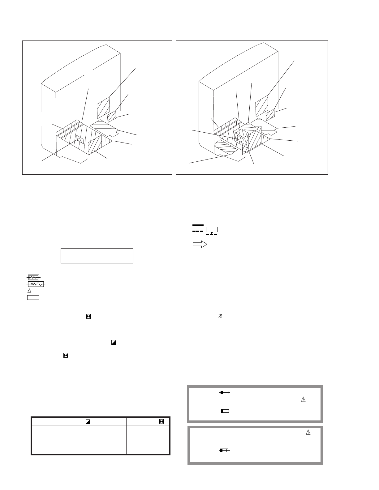
2-5-1. PICTURE TUBE REMOVAL (KV-32S40/34SL40/34SL40C/32S45/34SL45/34SL40T/32V40/32V65/34VL65/34VL65C)
WARNING -- Before removing
anode cap:
High voltage remains in the CRT even
after the power is disconnected.
To avoid electrical shock, discharge CRT
before attempting to remove the anode
cap. Short between anode and coated
earth ground strap of CRT.
Picture tube
shield assy
C board
Four screws
(Tapping screw 7)
G board
Chassis
Neck assy
Deflection yoke
Anode cap
Coated earth ground strap
2-5-2. PICTURE TUBE REMOVAL (KV-35S40/35S45/37SL45/37VL65/37VL65C)
WARNING -- Before removing
anode cap:
High voltage remains in the CRT even
after the power is disconnected.
To avoid electrical shock, discharge CRT
before attempting to remove the anode
cap. Short between anode and coated
earth ground strap of CRT.
Neck assy
Degaussing coil
C board
K board
(KV-32V65/34VL65/
34VL65C)
Picture tube
Cushion
G board
Chassis assy
K board
(KV-35V65/37VL65
/37VL65C)
Coated earth ground strap
Deflection yoke
Two Degaussing
coil holders
Four screw
(Tapping
screw )
Anode cap
— 11 —
Tension spring(B)
Claw
Two Degaussing
coil holders
Picture tube
Cushion
KV-32S40/32S45/34SL40/34SL40C/34SL40T/34SL45/35S40/35S45/37SL45/
32V40/32V65/34VL65/34VL65C/35V65/37VL65/37VL65C
SET-UP ADJUSTMENTS
SECTION 3
The following adjustments should be made when a
Perform the adjustments in order as follows:
complete realignment is required or a new picture
tube is installed.
1. Beam Landing
2. Convergence
These adjustments should be performed with rated
power supply voltage unless otherwise noted.
The controls and switch should be set as follows
3. Focus
4. Screen (G2)/White Balance
Note: Test Equipment Required
unless otherwise noted:
1. Color Bar Pattern Generator
PICTURE control ................. normal
2. Degausser
3. DC Power Supply
BRIGHTNESS control ......... normal
4. Digital Multimeter
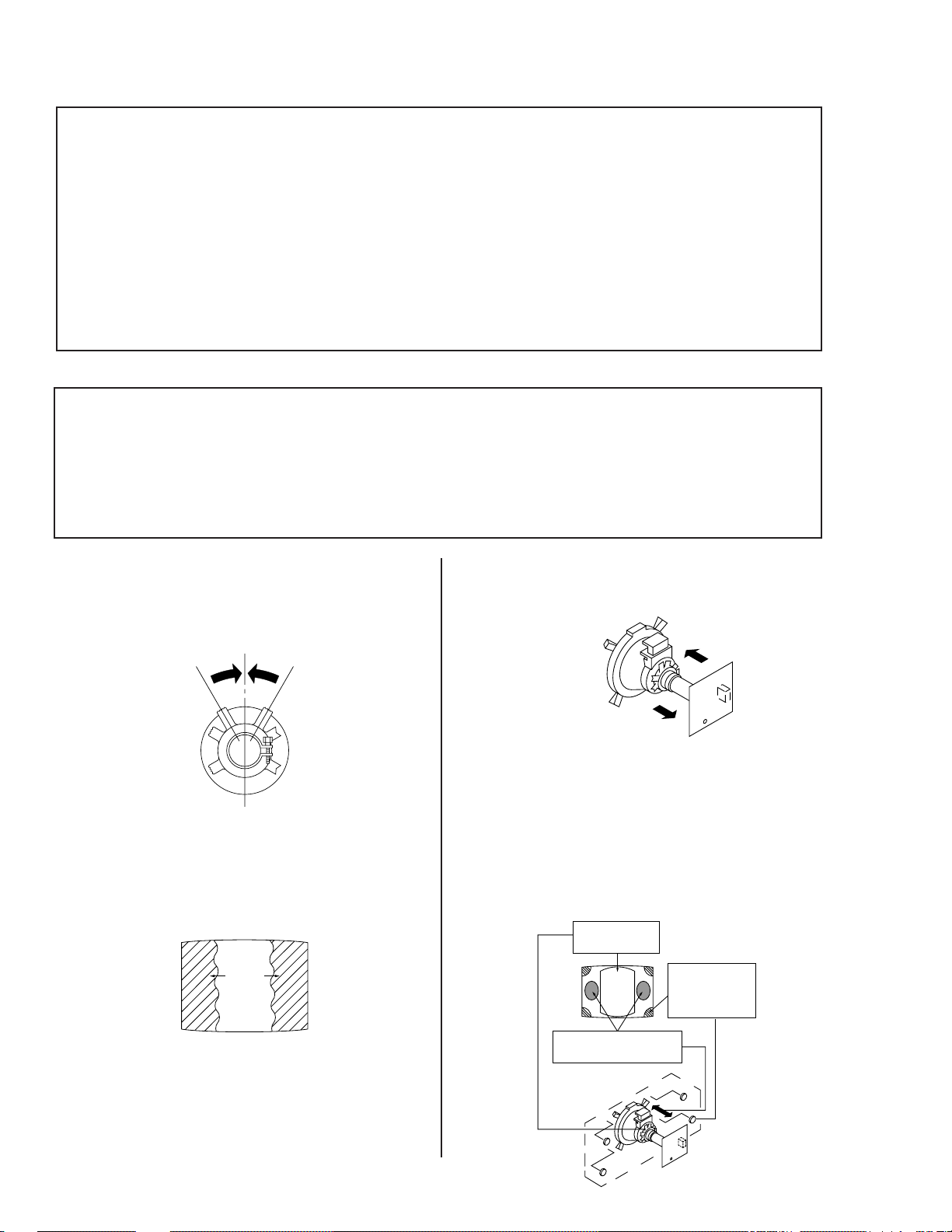
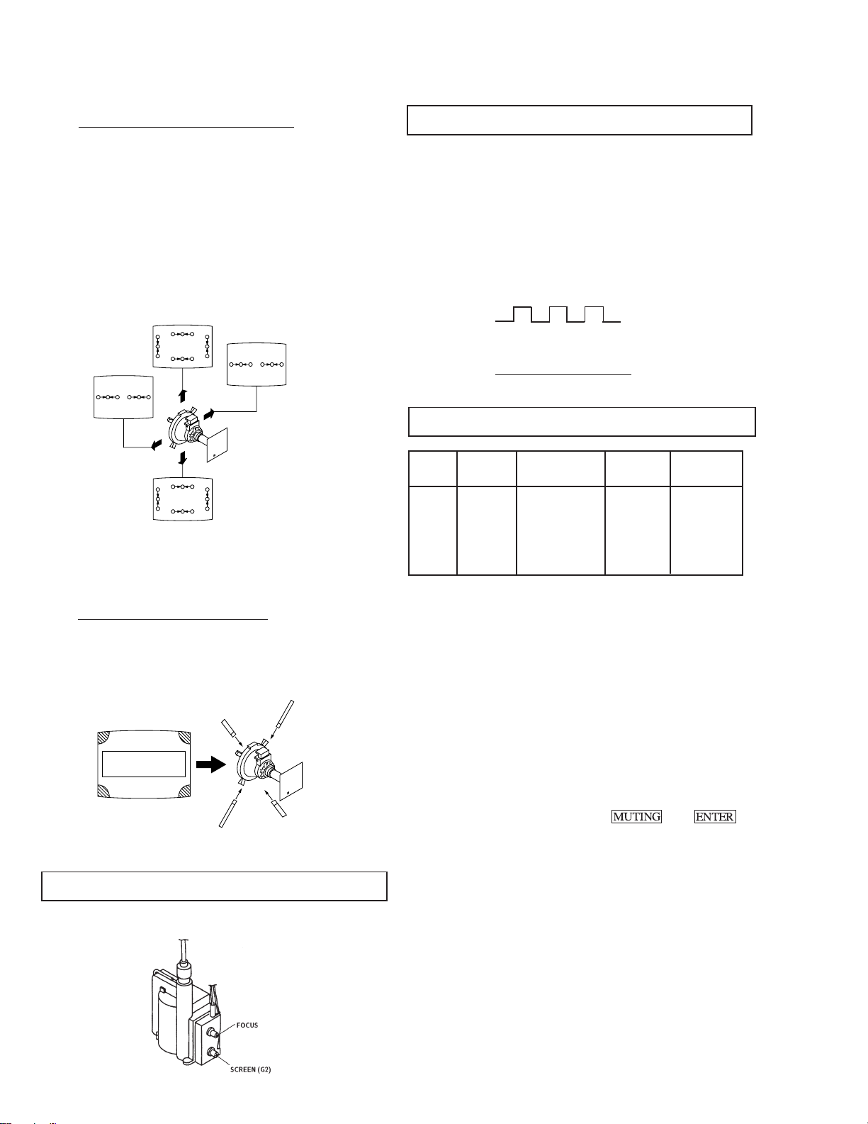
3-1. BEAM LANDING
Preparation:
• Input a white pattern signal.
• Face the picture tube in a East or West direction to reduce the influence of geomagnetism.
NOTE: Do not use the hand degausser because it magnetizes the CRT .
1. Input white pattern from pattern generator.
2. Loosen the deflection yoke mounting screw, and set
the purity control to the center as shown below:
5. Move the deflection yoke forward, and adjust so that the
entire screen becomes green.
3. Input green pattern from pattern generator.
4. Move the deflection yoke backward, and adjust with
the purity control so that green is in the center and
red and blue are even on both sides.
BR
G
6. Switch over the raster signal to red and blue and confirm
the condition.
7. When the position of the deflection yoke is determined,
tighten it with the deflection yoke mounting screw.
8. When landing at the corner is not right, adjust by using
the disk magnets.
Purity control
corrects this area.
Disk magnets or
ab
rotatable disk
cd
Deflection yoke positioning
corrects these areas.
a
d
magnets correct
these areas(a-d).
b
c
— 12 —
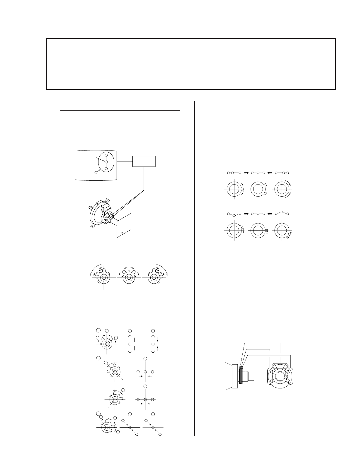
3-2. CONVERGENCE
Purity
V. STAT
BMC (Hexapole)
Preparation:
• Before starting, perform FOCUS, V. LIN and V. SIZE adjustments.
• Set BRIGHTNESS control to minimum.
• Input dot pattern.
KV-32S40/32S45/34SL40/34SL40C/34SL40T/34SL45/35S40/35S45/37SL45/
32V40/32V65/34VL65/34VL65C/35V65/37VL65/37VL65C
(1) Vertical and Horizontal Static Convergence
1. Adjust V. STAT magnet to converge red, green and blue
dots in the center of the screen. (Vertical movement)
Center dot
R
G
B
V.STAT
Magnet
Tilt the V. STAT magnet and adjust static convergence
to open or close the V. STAT magnet.
Operation of BMC (Hexapole) Magnet
The respective dot positions resulting from moving each
magnet interact, so perform adjustment while tracking.
Use the VSTAT tabs to adjust the red, green, and blue dots
so they line up at the center of the screen (move the dots in
a horizontal direction.)
RG B
RGB RGB
RGB
RGB
RGB
Y Separation Axis Correction Magnet Adjustment
1. Input cross-hatch pattern, adjust PICTURE to
minimum and BRIGHTNESS to normal.
2. When the V. STAT magnet is moved in the direction of
arrow a and b, red, green, and blue dots move as
shown below:
b
1
2
3
a
a
b
a
b
b
R
b
a
B
G
R
a
G
a
RG B
b
BG R
B
B
b
B
G
R
b
G
R
— 13 —
2. Adjust the deflection yoke upright so it touches the
CRT.
3. Adjust so that the Y separation axis correction magnet
on the neck assembly is symmetrical from top to
bottom (open state).
4. Return the deflection yoke to its original position.
KV-32S40/32S45/34SL40/34SL40C/34SL40T/34SL45/35S40/35S45/37SL45/
32V40/32V65/34VL65/34VL65C/35V65/37VL65/37VL65C
( 2 ) Dynamic Convergence Adjustment
• Before starting, perform Horizontal and Vertical
Static Convergence Adjustment.
1. Slightly loosen deflection yoke screw.
2. Remove deflection yoke spacers.
3. Move the deflection yoke for best convergence as
shown below:
R
B
BGR
G
G
RGB
R
RGB
BGR
B
B
RGB
G
BGR
R
R
G
B
RGB RGB
4. Tighten the deflection yoke screw.
5. Install the deflection yoke spacers.
3-4. SCREEN (G2)
1. Input dot pattern from the pattern generator.
2. Set the PICTURE and BRIGHT controls at normal.
3. Adjust S BRT, G CUT, B CUT in service mode with an
oscilloscope so that voltages on the red, green, and blue
cathodes are 170Vdc for 35"/37" and 180Vdc for 32"/34".
4. Observe the screen and adjust SCREEN (G2) VR
to obtain the faintly visible background of dot signal.
N
NN
NN
170Vdc
170 V dc/ 180 V dc
GND
NN
NN
N
N
NN
NN
pedestal
3-5. WHITE BALANCE ADJUSTMENTS
NO. Disp. Item Avg/32" Avg/35"
16 GDRV Green Drive 33 45
17 BDRV Blue Drive 33 45
18 GCUT Green Cut-off 3 6
19 BCUT Blue Cut-off 2 6
23 SBRT Sub Bright 14 10
(3) Screen-corner Convergence
Affix a permalloy assembly corresponding to the
misconverged areas:
b
c
a
ab
a-d : screen-corner
misconvergence
cd
d
3-3. FOCUS
Adjust FOCUS control for best picture.
1. Input an entire white signal.
2. Set to Service adjustment Mode.
3. Set DCOL to "0"
4. Set the PICTURE and BRIGHT to minimum.
5. Adjust with SBRT if necessary.
6. Select GCUT and BCUT with 1 and 4 .
7. Adjust with 3 and 6 for the best white balance.
8. Set the PICTURE and BRIGHT to maximum.
9. Select GDRV and BDRV with 1 and 4 .
10. Adjust with 3 and 6 for the best white balance.
11. Reset DCOL to "1".
12. Write into the memory by pressing
then **.
— 14 —
dejital
ge
KV-32S40/32S45/34SL40/34SL40C/34SL40T/34SL45/35S40/35S45/37SL45/
32V40/32V65/34VL65/34VL65C/35V65/37VL65/37VL65C
SECTION 4
SAFETY RELATED ADJUSTMENTS
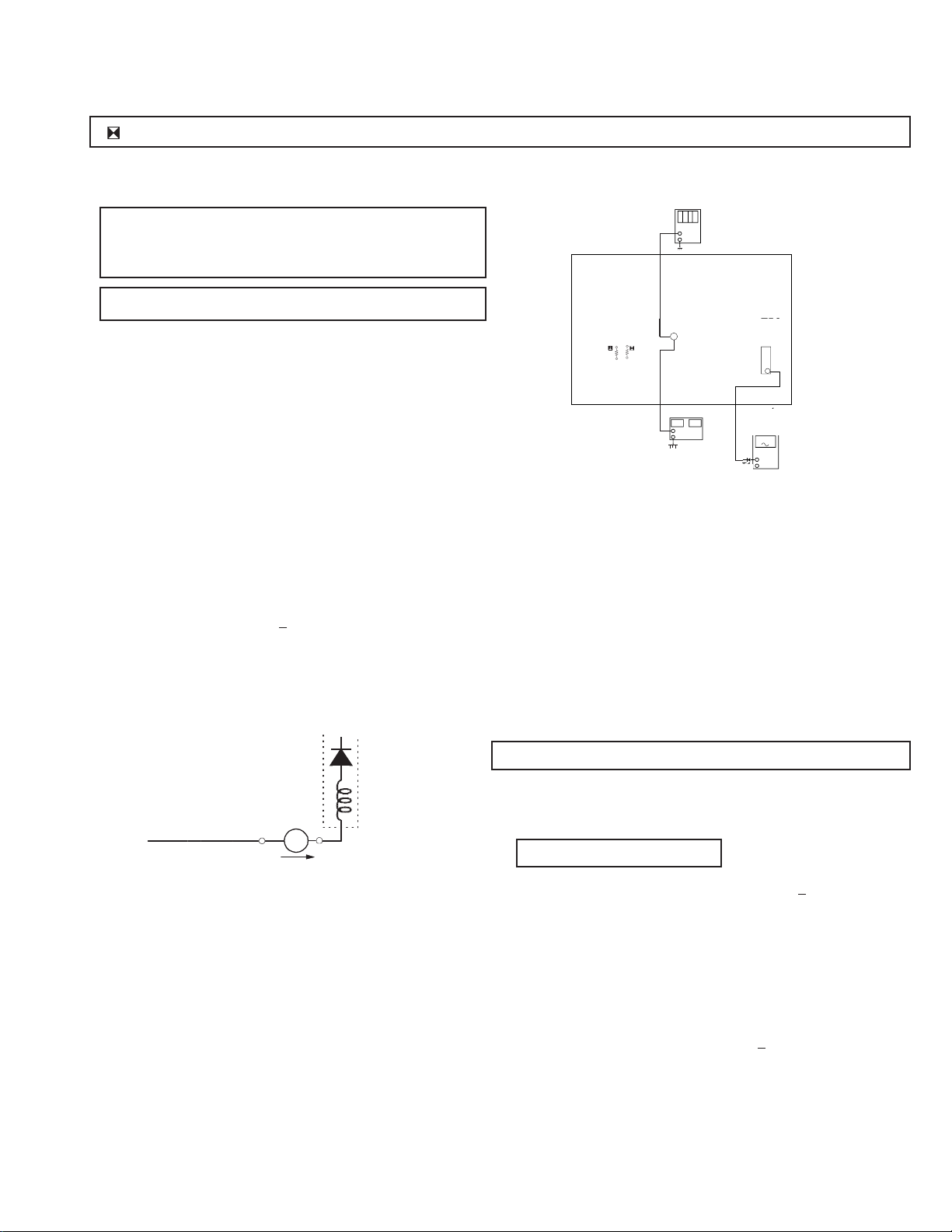
R530, R531 CONFIRMATION METHOD (HOLD-DOWN CONFIRMATION) AND READJUSTMENTS
Always perform the following adjustments when replacing the following
components marked with a ] mark on the schematic diagram:
A BOARD: IC351, IC501, D519, D520, D521, C531,
C532, R387, R529, R530, R531, R532,
R533, R550, T503
G BOARD: IC643, R661
Step 1 Preparation before Confirmation
Turn the POWER switch ON.
Input a white signal and set the PICTURE and BRIGHT
controls to maximum.
Confirm that the voltage at the check terminal of TP85 is
more than 18.0 V DC when the set is operating normally.
At AC input: 120.0 ± 2.0 VAC
or220.0 ± 2.0 VAC (for 34SL40C/34VL65C/37VL65C only)
R531
R531
DC Power Supply
A BOARD - CONDUCTOR SIDE
digital multimeter
multimeter
+
-
TP85
TP85
R530
R530
+
-
dc power supply
T503
T503
FBT
FBT
11
ammeter
ammeter
3mA dc ran
3mA DC range
A
+
-
1T40
Step 2
Step 3
Step 4
Input a white signal and verify that I ABL is within the
specified range:
2160 + 100 µA.
At AC input: 120.0 ± 2.0 VAC
or 220.0 ± 2.0 VAC (for 34SL40C/34VL65C/37VL65C only)
T504
FBT
ammeter
3.0 mA DC
range
ABL
+
I ABL
-
A
Record the voltage between TP85 and ground.
Using an external DC power supply, apply voltage
between TP85 and ground.
Step 5
Confirm that a voltage of more than 18.0 V DC appears
between TP85 and ground.
At AC input: 120.0 ± 2.0 VAC
or 220.0 ± 2.0 VAC (for 34SL40C/34VL65C/37VL65C only)
B+ VOL TAGE CONFIRMATION AND ADJUSTMENT
Always perform the following adjustments when replacing the
following components marked with ] on the schematic diagram:
G BOARD: IC643, R661
1) Using Variac, apply AC input voltage: 130
(or 220.0 ± 2.0 VAC
for 34SL40C/34VL65C/37VL65C only)
2) Input a monoscope signal.
3) Set the PICTURE control and the BRIGHT control to
initial reset value.
+ 2.0 VAC
Increase the voltage gradually and confirm that the
holdown works (raster disappears) at lower than the
voltage recorded in Step 3.
Lower than 22.05 V DC
At AC input: 120.0 ± 2.0 VAC
or 220.0 ± 2.0 VAC (for 34SL40C/34VL65C/37VL65C only)
— 15 —
4) Confirm the voltage of G BOARD CN641 between
pin 1 to ground is less than 135.5
+ 1.0 V DC.
5) If step 4 is not satisfied, replace the R661and repeat the
above steps.
KV-32S40/32S45/34SL40/34SL40C/34SL40T/34SL45/35S40/35S45/37SL45/
32V40/32V65/34VL65/34VL65C/35V65/37VL65/37VL65C
SECTION 5
CIRCUIT ADJUSTMENTS
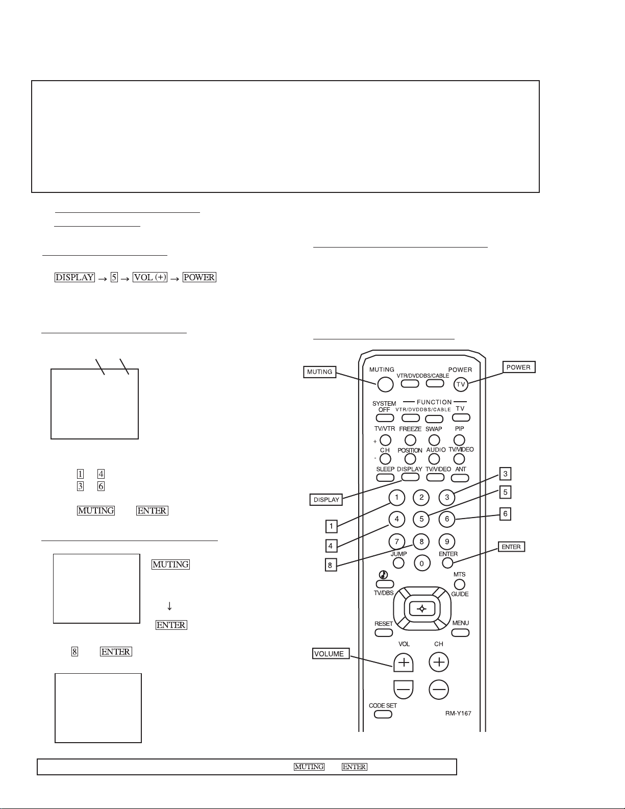
ELECTRICAL ADJUSTMENT BY REMOTE COMMANDER
Use Remote Commander (RM-Y167) to perform the following circuit adjustments:
NOTE : Test Equipment Required:
1. Pattern Generator
2. Frequency Counter
3. Digital Multimeter
4. Audio OSC
(1) Method of Setting the Service
Adjustment Mode
SERVICE MODE PROCEDURE
1. Standby mode. (Power off)
2.
on the
Remote Commander.
(Press each button within a second.)
SERVICE ADJUSTMENT MODE IN
Disp.
Item
(Item)
data
SERVICE AFC 0
3. The CRT displays the item being adjusted.
4. Press
5. Press
or on the Remote Commander to select the item.
or on the Remote Commander to change the
data.
6. Press
then to write into memory**.
8. Turn set off and on to exit. * CAUTION: Wait at least
10 seconds before turning off set.
(2) Memory Write Confirmation Method
1. After adjustment, pull out the plug from the AC outlet,
then replace the plug in the AC outlet again.
2. Turn the power switch ON and set to Service Mode.
3. Call the adjusted items again to confirm they were adjusted.
(3) Adjust Buttons and Indicator
SERVICE ADJUSTMENT MODE MEMORY
SERVICE RESET
Green
Red
7. Press
then on the Remote Commander to
initialize.
SERVICE WRITE
Carry out step 7 when adjusting
IDs 0 to 4 and when replacing
and adjusting IC002.
RM-Y167
**WARNING: Do NOT turn off the power or AC immediately after pressing then . Wait at least 10 seconds.
— 16 —
KV-32S40/32S45/34SL40/34SL40C/34SL40T/34SL45/35S40/35S45/37SL45/
p
g
p
32V40/32V65/34VL65/34VL65C/35V65/37VL65/37VL65C
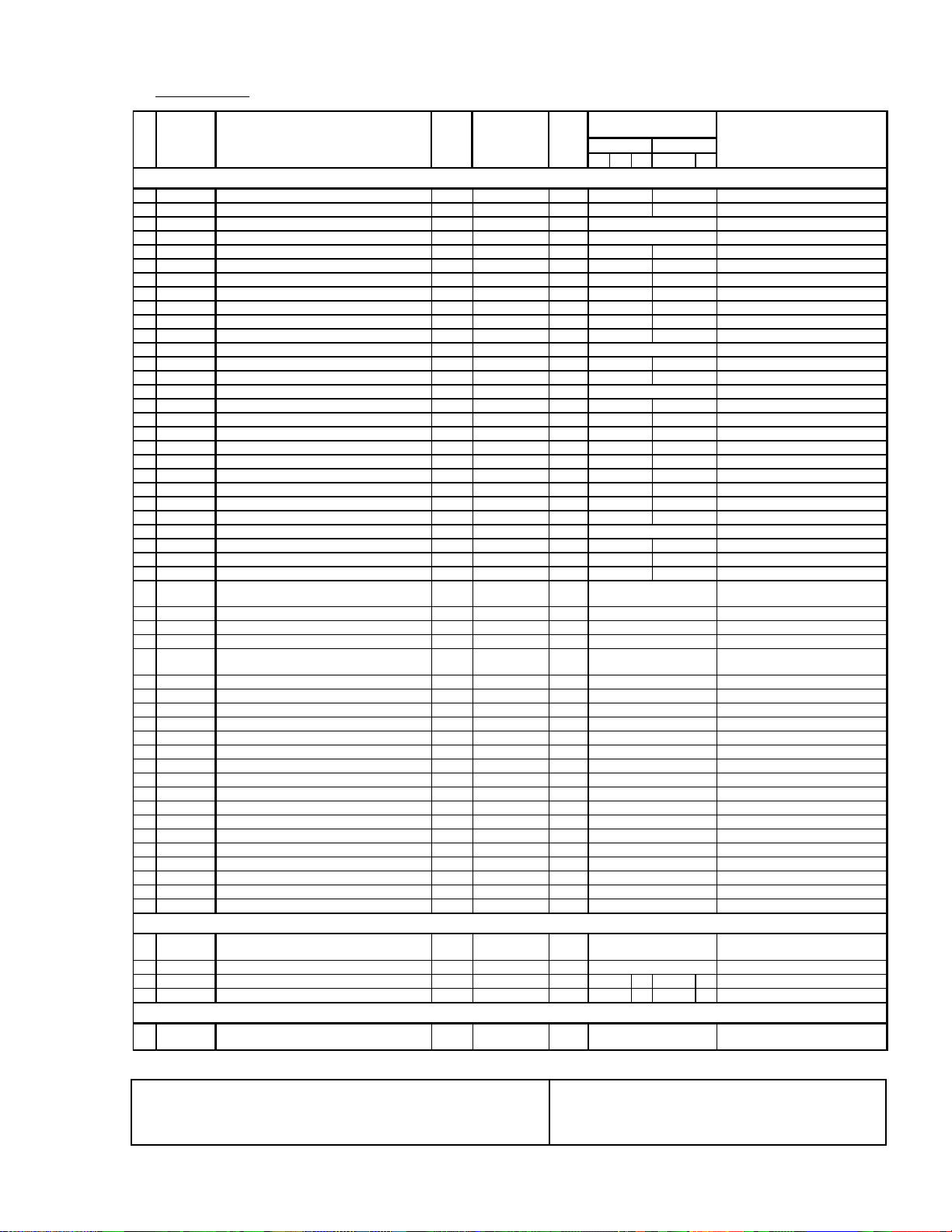
(4) Service Data
Register
No.
Name
Description Data Adj/Fix Initial Average Data** Comments
Range Data 32" 35"
A B C D E
VP CXA2095S
1
VPOS V-Position 0-63 Adj 20 23 27 0:Down, 63:Up
2
VSIZ V-Size 0-63 Adj 20 27 26 0:Min, 63:Max
3
VCOM V-Compensation 0-3 Fix 1 1 0:Min, 3:Max
4
VLIN V-Linearity 0-15 Adj 7 9 0:Min, 15:Max
5
VSCO S-Correction 0-15 Adj 7 6 9 0:Min, 15:Max
6
HPOS H-Position 0-15 Adj 7 11 10 0:Right, 15:Left
7
HSIZ H-Size 0-63 Adj 20 23 28 0:Min, 63:Max
8
PAMP Pin Compensation 0-63 Adj 31 2 7 24 0:Min, 63:Max
9
UPIN Upper Corner Pin 0-15 Adj 7 4 7 0:Min, 15:Max
10
LPIN Lower Corner Pin 0-15 Adj 7 6 1 0 0:Min, 15:Max
11
PPHA Pin Phase 0-15 Adj 7 4 5 0:Min(small picture), 15:Max
12
AFC AFC 0-3 Fix 2 2 0:Freerun, 1:Min, 3:Max
13
VBOW AFC Bow 0-15 Adj 7 6 5 0:Right, 15:Left
14
VANG AFC Angle 0-15 Adj 7 6 4 0:Right, 15:Left
15
REF Reference Line 0-3 Fix 2 2 0:22H(Rch), 3:16H(Rch)
16
GDRV Green Drive 0-63 Adj 31 22 35 0:Min, 63:Max
17
BDRV Blue Drive 0-63 Adj 31 30 26 0:Min, 63:Max
18
GCUT Green Cutoff 0-15 Adj 7 5 8 0:Min, 15:Max
19
BCUT Blue Cutoff 0-15 Adj 7 7 6 0:Min, 15:Max
20
SCON Sub Contrast 0-15 Adj 7 10 8 0:Min, 15:Max
21
SHUE Sub Hue (RF only) 0-15 Adj 7 7 (flat-1) 8 (flat-1) 0:+10deg, 15:-10deg
22
1SHU Sub Hue (composite & S-video) 0-15 Adj 7 7 7 0:+10deg, 15:-10deg
23
SCOL Sub Color (RF only) 0-15 Adj 7 11 (flat+2) 9 (flat+2) 0:Min, 15:Max
24
1SCO Sub Color (composite & S-video) 0-15 Adj 7 14 13 0:Min, 15:Max
25
SBRT Sub Brightness 0-63 Adj 31 26 0:Min, 63:Max
26
SSHP Sub Sharpness (RF & Composite video) 0-15 Fix by model 7 8 8 0:Min, 15:Max
27
1SSP Sub Sharpness (S-video only) 0-15 Fix by model 7 10 10 0:Min, 15:Max
28
GMMA Gamma Correction 0-3 Fix by model 1 0 0 0:Off, 1:Min, 3:Max
29 CDM2 Countdown Mode 2 0-1 Fix 0 0
30
EYSW External Y Switch 0-1 Fix 0 0 0: Normal 1: EYin disabled
31
DPIX Dynamic Picture 0,1 Fix 1 1 0:Off, 1:On
32
Y-DC DC Transmission Ratio 0,1 Fix 1 1 0:100%, 1:82%
33 ABLM ABL Mode 0,1 Fix 1 1
34
AXIS Color Demodulation Axis 0,1 Fix 1 1 0:Japan, 1:US
35
NOTC Chroma Trap Filter 0,1 Fix 0 0 0:Off, 1:On
36
CROM Chroma Trap Adjust 0-15 Fix 7 7 0:+300kHz, 1:-300kHz
37
TOT TOT Filter (RF only) 0,1 Fix 1 1 0:Off, 1:On
38
1TOT TOT Filter (Composite & S-video) 0,1 Fix 1 0 0:Off, 1:On
39
PREL Pre/Overshoot Ratio (RF & Composite) 0-3 Fix by model 3 1 0: 2:1, 3: 5:1
40
1PRE Pre/Overshoot Ratio (S-video only) 0-3 Fix by model 3 3 0: 2:1, 3: 5:1
41
SHPF Sharpness fo (RF & Composite) 0-3 Fix by model 2 1 0:2.5MHz, 3:4.0MHz
42
1SPF Sharpness fo (S-video only) 0-3 Fix by model 2 3 0:2.5MHz, 3:4.0MHz
43
RON Red Off 0,1 Fix 1 1 0:Off, 1:On
44
GON Green Off 0,1 Fix 1 1 0:Off, 1:On
45
BON Blue Off 0,1 Fix 1 1 0:Off, 1:On
46
DCOL Dynamic Color 0,1 Fix 0 1 0:Off, 1:On
47
CDMD V Countdown Mode 0,1 Fix 0 0 0:Auto, 1:Fix
48
HBSW H Blanking Switch 0,1 Fix 0 0 0:Off, 1:On
49
LBLK Left Blanking 0-15 Fix 0 7 0:Min, 15:Max
50 RBLK Righ t Blanking 0-15 Fix 0 7
0: Normal 1: High Speed
Countdown Res
0:PictureABL,
1:Picture/Bri
0:Min, 15:Max
AP CXA2021
51 SVOL Sub Volume 0-15 Fix 0 6
52
SBAL Sub Balance 0-15 Adj 7 7 0: +Right, 15:+Left
53
SBAS Sub Bass 0-15 Fix by model 7 10 8 10 8 0:-7 Steps, 15: +8 steps
54 STRE Sub Treble 0-15 Fix by model 7 710710
0:-0 Volume steps, 15:-15
Volume ste
0:-7 Steps, 15: +8 steps
MM1311/1313
55
AUSW Audio Att Sw 0,1 Fix 1 1
0:-6dB, 1:0dB (Only for VIDEO
input)
onse
htnessABL
s
**AVERAGE DATA MODEL GROUPINGS:
32"/34" A: KV-32S40/32S45/34SL40/34SL40C/34SL40T/34SL45 35"/37" D: KV-35S40/35S45/37SL45
B: KV-32V40 E: KV-35V65/37VL65/37VL65C
C: KV-32V65/32VL65/34VL65C
**WARNING: Do NOT turn off the power or AC immediately after pressing then . Wait at least 10 seconds.
— 17 —
KV-32S40/32S45/34SL40/34SL40C/34SL40T/34SL45/35S40/35S45/37SL45/
)
)
p
)
32V40/32V65/34VL65/34VL65C/35V65/37VL65/37VL65C
Service Data (cont.)
Register
No.
Name
Description Data Adj/Fix Initial Average Data** Comments
Range Data 32" 35"
A B C D E
PI SDA9288
56
PYSD Select Delay 0-15 Fix by P-bd 3 3 0:Right, 15:Left
57
PIPH PIP H-position 0-127 Fix 78 78 0:Right, 127:Left
58
PIPV PIP V-position 0-63 Fix 1 8 18 0:Up, 63:Down
59
PYDL PIP Y-delay 0-7 Fix 0 0 0:Right, 7:Left
60
PHDL H-pulse delay 0-15 Fix by P-bd 3 0 0:Right, 15:Left
61 PMVD Main V-pulse delay 0-31 Fix 1 6 16
62 PIVD Inset V-pulse delay 0-31 Fix 2 2 22
63
PCON Inset Contrast 0-15 Fix 7 7 0:Min, 15:Max
64
FRMY Frame Y 0-15 Fix 7 7 0:Dark, 15:Bright
65 CHRI Input Polarity 0,1 Fix by P-bd 1 1
66 CHRO Output Polarity 0,1 Fix 1 1
67
IPER Inset Pedestal R-Y 0-15 Fix 0 0 0:Center, 7:Max, 8:Min
68
IPEB Inset Pedestal B-Y 0-15 Fix 0 0 0:Center, 7:Max, 8:Min
69 PCPS CLPS Bit Control 0,1 Fix 0 0
70
PCPF CLPFIX Bit Control 0,1 Fix 0 0 0: 3Clamp line, 1: 2Clamp line
71
PSEL SELDOWN Bit Control 0,1 Fix by P-bd 1 1 0:Open out, 1:TTL out
72
PPLL PLL Filter Bits 0-3 Fix 0 0 Fixed value only
73 PVNR VSPISQ VSP NR 0-1 Fix 0 1
IC CXA2019
74
ISCO CDec Sub Contrast 0-15 Fix 7 15 PiP sub contrast
75
ISHP CDec Sharpness 0-15 Fix 7 8 PiP sharpness
76
ISCL CDec Sub Color 0-15 Fix 7 9 PiP sub color
77
ISHU CDec Sub Hue 0-15 Fix 7 6 PiP sub hue
78
ITOT CDec TOT on 0,1 Fix 0 1 PiP TOT 0:Off, 1:On
79
IAFC CDec AFC 0-3 Fix 2 2 0:Max, 2:Min, 3:Freerun
80
ICD2 CDec Countdown Mode2 0,1 Fix 0 0 0:Standard, 1:Fast
81
IYDR CDec Y drive 0-31 Fix 1 5 7 PiP Y-drive gain
82
IVPE CDec V pedestal 0-15 Fix 7 6 PiP V-ped DC
83
IUPE CDec U pedestal 0-15 Fix 7 6 PiP U-ped DC
84
IRVP CDec RV pedestal 0-15 Fix 7 6 PiP V-ped DC (re-input)
85
IRUP CDec RU pedestal 0-15 Fix 7 6 PiP U-ped DC (re-input)
86
IDCT CDec DC transfer 0-7 Fix 2 0 PiP DC transfer 0:Max, 7:Min
87
IRYD CDec RY drive 0-31 Fix 1 5 20 PiP RY Drive (re-input)
88
IABO CDec ABL off 0,1 Fix 1 1 PiP ABL (RY-OUT) 0:On, 1:Off
89
IPRE CDec Pre/Over shoot 0-3 Fix 3 3 PiP Pre/over shoot 0: 1:1, 1: 4:1
90 IRUD CDec RU Drive 0-31 Fix 1 5 20
91
IABL CDec ABL 0,1 Fix 1 1 PiP ABL gain 0:Std, 1:Min
92
IABC CDec ABL Cent 0-3 Fix 1 1 PiP ABL Center 0:Min, 1:Max
93
IRVD CDec RV drive 0-31 Fix 15 17 PiP RY Drive (re-input)
94 IDLY CDec Delay 0-3 Fix 0 0
95 ISCR CDec SCP BGR 0-3 Fix 0 0
96
ISCF CDec SCP BGF 0-3 Fix 0 0
CC CXP8584a-011s
97 CRIL CC CRI count low 0-15 Fix 2 2
98
CFLD CC Caption Fixed Field Count Fix 5 5 Fixed value only
99
CCDI CC CCD int 0-7 Fix 3 3 Fixed value only
100
CRIP CC CRI & polarity 0-7 Fix 4 4 Fixed value only
101
CRIT CC CRI time constant 0-3 Fix 1 1 Fixed value only
102
CSB1 CC Sync Slice Bias 1 0-3 Fix 3 3 Fixed value only
103
CSB2 CC Synce Slice Bias 2 0-7 Fix 4 4 Fixed value only
104
CREP CC CRI signal end position 0-255 Fix 1 42 142 Fixed value only
105
CDSD CC Data start delay 0-31 Fix 8 8 Fixed value only
106
CCDS CC Caption data threshold 0-31 Fix 9 9 Fixed value only
107
CHMK CC P8_HMASK 0-63 Fix 4 2 42 Hmask
108
CHSY CC P8_HSYC 0-255 Fix 1 36 136 Hsyc
109
DISP TV OSD H Position 0-63 Adj 1 2 3 0:Off, 1:Left, 63: Right
110 RTCO Rotation Coil 0-63 Fix 3 2 32
**AVERAGE DATA MODEL GROUPINGS:
32"/34" A: KV-32S40/32S45/34SL40/34SL40C/34SL40T/34SL45 35"/37" D: KV-35S40/35S45/37SL45
B: KV-32V40 E: KV-35V65/37VL65/37VL65C
**WARNING: Do NOT turn off the power or AC immediately after pressing then . Wait at least 10 seconds.
C: KV-32V65/32VL65/34VL65C
7-21: Available (1-6/22-31 Not
Avail
16-28 Available (1-15/29-31 Not
Avail
0:+(B-Y)+(R-Y), 1:-(B-Y)-(R-Y)
0:+(B-Y)+(R-Y), 1:-(B-Y)-(R-Y)
0:Depend on HSIDEL, 1:Not
end
de
SDA9288 IC bypass use 1
PiP RU-gain out 0:-6dB,
31:+3.3bD
PiP Y-delay 0:0ns, 1:60ns,
2:120ns, 3:180ns
PiP SCP riseup phase 0:+0.4us,
1:cent, 2:-0.8us
PiP SCP falldown phase
0:+0.4us, 1:cent, 2:-0.8us
7 Clock Run-In Lower Limit (field
1
Fixed value only
— 18 —
KV-32S40/32S45/34SL40/34SL40C/34SL40T/34SL45/35S40/35S45/37SL45/
32V40/32V65/34VL65/34VL65C/35V65/37VL65/37VL65C
Service Data (cont.)
Register
No.
Name
Description Data Adj/Fix Initial Average Data** Comments
Range Data 32" 35"
A B C D E
ID MAP
111
ID-0 ID-0 (Language/Color Systems) 0-255 Fix by model 8 9 See ID map
112
ID-1 ID-1 (Input/Output Conifguration) 0-255 Fix by model 5 5 See ID map
113
ID-2 ID-2 (Audio) 0-255 Fix by model 1 75 See ID map
114
ID-3 ID-3 (OSD/Timer/V-chip/Ch Fix) 0-255 Fix by model 0
115
ID-4 ID-4 (CC/Spot Killer/etc) 0-255 Fix by model 15 5
116
ID-5 ID-5 (V-series Features/etc) 0-255 Fix by model 141 See ID map
117
ID-6 ID-6 (PiP/Ant Sw related) 0-255 Fix by model 6 See ID map
118
ID-7 ID-7 (Special Models/etc) 0-255 Fix by model 0
**AVERAGE DATA MODEL GROUPINGS:
32"/34" A: KV-32S40/32S45/34SL40/34SL40C/34SL40T/34SL45 35"/37" D: KV-35S40/35S45/37SL45
B: KV-32V40 E: KV-35V65/37VL65/37VL65C
C: KV-32V65/32VL65/34VL65C
refer to
NVM ID Chart
See ID map
See ID map
See ID map
SERVICE IDO 25
(5) Feature ID Map
Note: Items 1-118 show adjustment order
KV-
DESTINATION
ID-0
ID-1
ID-2
ID-3
ID-4
ID-5
ID-6
1 32S40 (US/CND) 89 17 31 10 27 129 0 0
2 32S45 (US/CND) 89 21 31 10 27 129 1 0
3 32V40 (US/CND) 89 23 175 10 27 129 0 0
4 32V65 (CND) 89 55 175 10 27 141 6 0
6 35S40 (US/CND) 89 21 31 10 155 129 6 0
7 35S45 (US/CND) 89 21 31 10 155 129 1 0
8 35V65 (CND) 89 55 175 10 155 141 6 0
9 34SL40C (E) 25 17 159 74 59 129 0 0
10 34VL65C (E) 25 55 175 74 59 141 6 0
11 37VL65C (E) 25 55 175 74 187 141 6 0
12 34SL40 (E) 25 17 159 74 59 129 0 0
13 34SL45 (E) 25 21 159 74 59 129 1 0
14 34VL65 (E) 25 55 175 74 59 141 6 0
15 37SL45 (E) 25 21 159 74 187 129 1 0
16 37VL65 (E) 25 55 175 74 187 14 6 0
17 34SL40T (TAIWAN) 9 17 15 9 10 27 1 2 9 0 0
ID-7
**WARNING: Do NOT turn off the power or AC immediately after pressing then . Wait at least 10 seconds.
— 19 —
KV-32S40/32S45/34SL40/34SL40C/34SL40T/34SL45/35S40/35S45/37SL45/
32V40/32V65/34VL65/34VL65C/35V65/37VL65/37VL65C
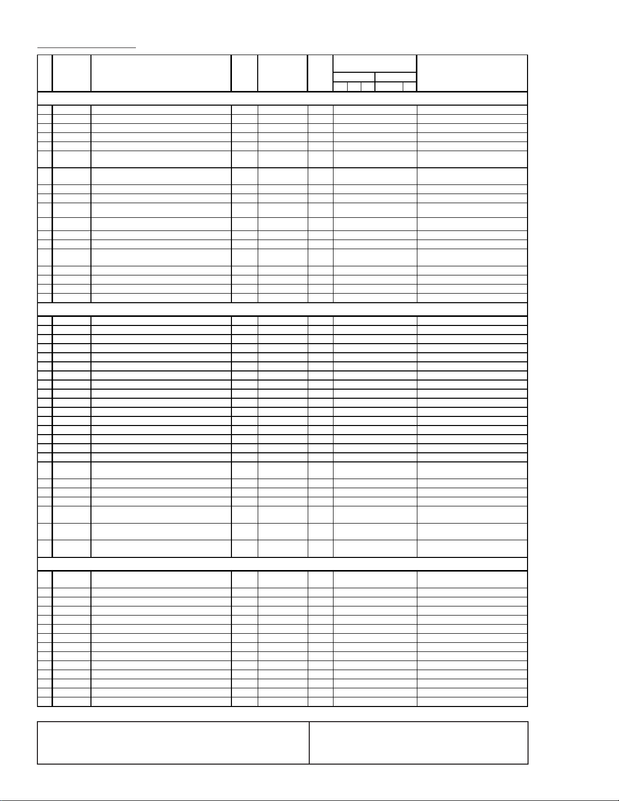
SUB BRIGHT ADJUSTMENT (SBRT)
1. Set to Service adjustment Mode.
2. Input a gray scale pattern signal.
3. Set the PICTURE to minimum, and BRIGHT to normal.
4. Select SBRT with and .
5. Adjust SUB BRIGHT level with and so that the stripe
second from the right is faintly visible.
6. Write into the memory by pressing then
**.
white
second from the right
black
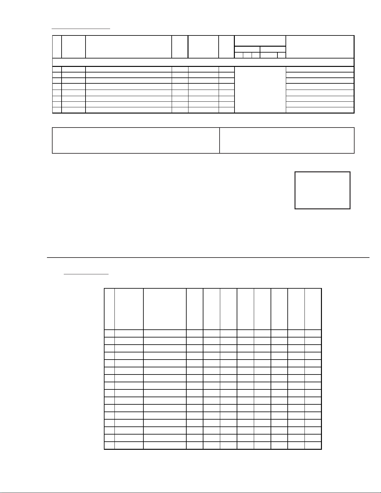
SUB CONTRAST ADJUSTMENT (SCON)
1. Input a color-bar signal.
2. Set to Service adjustment Mode.
3. Select the item DCOL to "0" level.
4. Set the conditions as follows.
10. Return the following back to normal after adjustment.
PICTURE . . . . . . . . . . . MAX
COLOR . . . . . . . . . . . CENTER
BRIGHT . . . . . . . . . . . CENTER
R ON . . . . . . . . . . . ON (1)
G ON . . . . . . . . . . . ON (1)
B ON . . . . . . . . . . . ON (1)
DISPLAY POSITION ADJUSTMENT (DISP)
1. Input a color-bar signal.
2. Set to Service adjustment Mode.
3. Select DISP with
and .
4. Adjust with and for adjustment of characters to center .
5. Write the memory by pressing
SERVICE AFC 0
then **.
PICTURE . . . . . . . . . . . MAX
COLOR . . . . . . . . . . . MIN
BRIGHT . . . . . . . . . . . CENTER
R ON . . . . . . . . . . . ON (1)
G ON . . . . . . . . . . . OFF (0)
B ON . . . . . . . . . . . OFF (0)
1: ON
0: OFF
SERVICE RON 1
5. Connect an oscilloscope probe to C Board, CN1761 pin 1
(RED OUT).
6. Select SCON with
7. Adjust with
and .
and for: 2.10 ± 0.01 Vp-p.
White
n
2.10 ± 0.1 Vp-p
n
Black
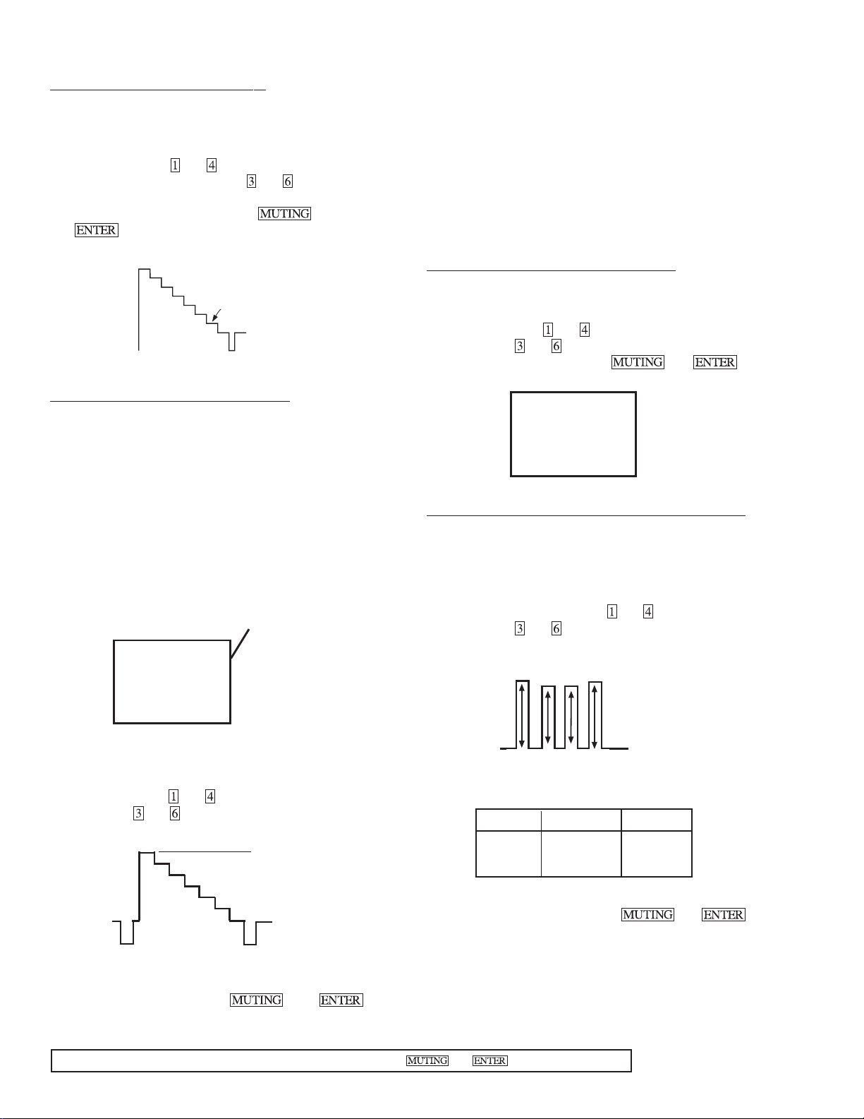
SUB HUE, SUB COLOR ADJUSTMENT (SHUE, SCOL)
1. Input a color-bar signal.
2. Set to Service adjustment Mode.
3. Connect oscilloscope probe to C Board, CN1761 Pin3
(BLUE OUT).
4. Select SHUE and SCOL with and .
5. Adjust with
and for the V1 = V4 ± 0.1Vp-p (SCOL)
and V2 = V3 ± 0.1Vp-p (SHUE).
V1
V2 V3
V4
6. Change data according to the following table;
SCOL SHUE
32" +2 steps -1 steps
35" +2 steps -1 steps
7. Write into the memory by pressing
then **.
8. Reset the item DCOL to "1" level.
9. Write the memory by pressing then ** .
**WARNING: Do NOT turn off the power or AC immediately after pressing then . Wait at least 10 seconds.
— 20 —
KV-32S40/32S45/34SL40/34SL40C/34SL40T/34SL45/35S40/35S45/37SL45/
32V40/32V65/34VL65/34VL65C/35V65/37VL65/37VL65C
V. SIZE ADJUSTMENT ( VSIZ)
1. Input a cross-hatch signal.
2. Set to Service adjustment mode.
3. Select VSIZ with
4.Adjust with
5.Write into the memory by pressing
and .
and for the best vertical size.
V. SIZE
/
V. POSITION ADJUSTMENT (VPOS)
1.Input a cross-hatch signal.
2.Set to Service adjustment Mode.
3.Select VPOS with
4.Adjust with
5.Write into the memory by pressing
V. POSITION
and .
and for the best vertical center.
then **.
/
then **.
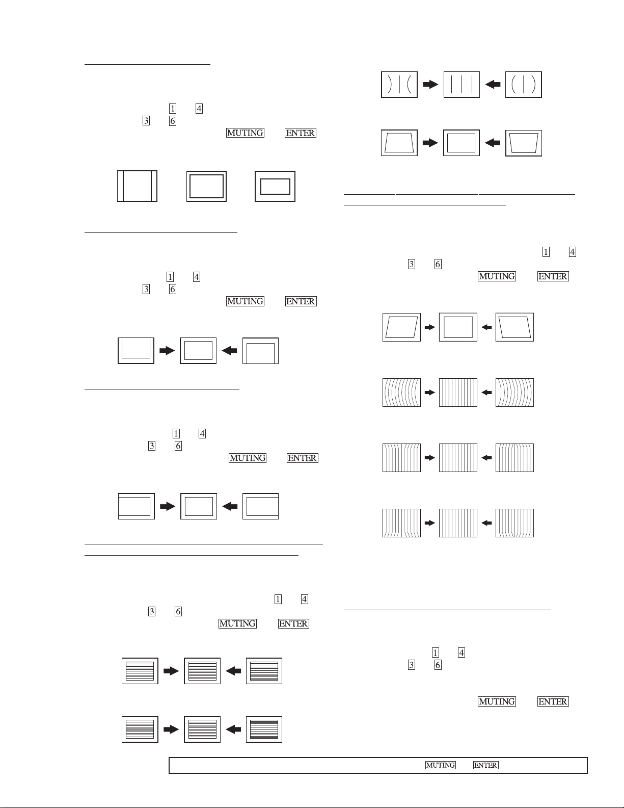
PIN AMP (PAMP)
PIN PHASE (PPHA)
V ANGLE (VANG), V BOW (VBOW), UPPER PIN (UPIN)
AND LOW PIN (LPIN) ADJUSTMENTS
1. Input a cross hatch signal.
2. Set to Service adjustment Mode.
3. Select VVANG, VBOW, UPIN, and LPIN with
4. Adjust with
5. Write the memory by Pressing
V ANGLE (V ANG)
V BOW (VBOW)
and for the best picture.
then ** .
and .
H. POSITION ADJUSTMENT (HPOS)
1. Input a cross-hatch signal.
2. Set the Service adjustment Mode.
3. Select HPOS with
4. Adjust with
5. Write into the memory by pressing
and .
and for the best horizontal center.
then **.
H. POSITION
V LINEARITY (VLIN), V CORRECTION (VSCO), PIN AMP
(PAMP) AND PIN PHASE (PPHA) ADJUSTMENTS
1. Input a cross-hatch signal.
2. Set to Service adjustment Mode.
3. Select VLIN, VSCO, PAMP, and PPHA with and .
4. Adjust with
5. Write the memory by Pressing
V LINEARITY(VLIN)
VS CORRECTION (VSCO)
and for the best picture.
then ** .
UPPER PIN (UPIN)
LOW PIN (LPIN)
P BOARD ADJUSTMENTS
PIP V. POSITION (PIPV), PIP H. POSITION (PIPH)
1. Input a color bar signal.
2. Set to service adjustment mode.
3. Select PHOP with and .
4. Adjust with
corner P in P display position.
5. Adjust P in P put at lower right position.
6. Write the memory by Pressing then **.
and for the best balanced position at four
**WARNING: Do NOT turn off the power or AC immediately after pressing then . Wait at least 10 seconds.
— 21 —
6-3. CIRCUIT BOARDS LOCATION
S MODELS
V MODELS
C
HS
(KV-32S45/32SL45/
35S40/35S45/37SL45)
WA
(KV-32S40/34SL40/
34SL40C/32S45/34SL45)
HV
(KV-35S40/
35S45/37SL45)
WB
(KV-35S40/32SL45/
35S45/37SL45)
G
P
(EXCEPT
KV-32V40)
A
P
(KV-32S45/32SL45/35S45/37SL45)
B
K
(EXCEPT KV-32V40)
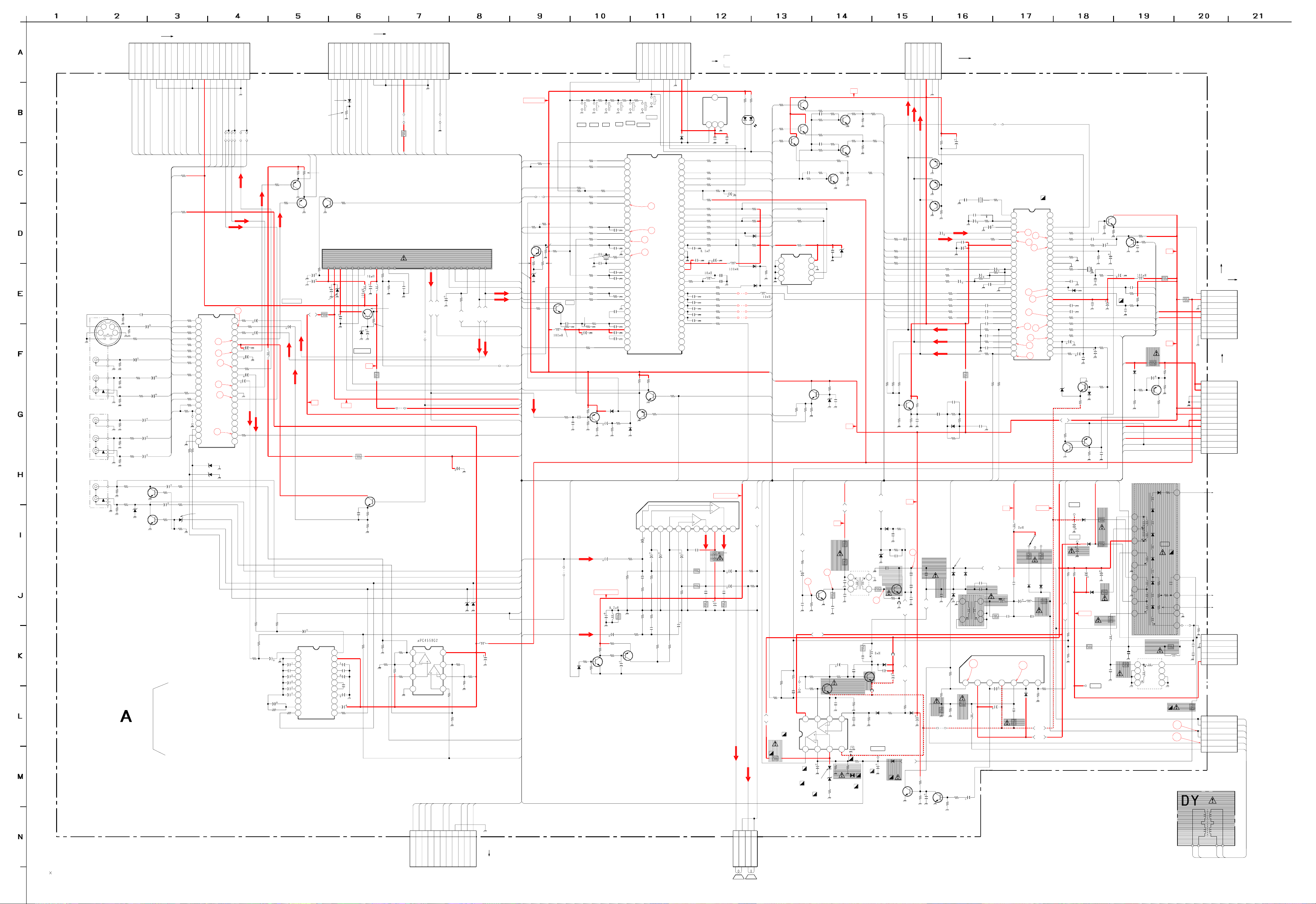
6-4. PRINTED WRING BOARDS AND SCHEMATIC DIAGRAMS
• All capacitors are in µF unless otherwise noted. pF : µµF 50WV or less are not
indicated except for electrolytics and tantalums.
• All electrolytics are in 50V unless otherwise specified.
• All resistors are in ohms.
KΩ=1000Ω, MΩ=1000kΩ
• Indication of resistance, which does not have one for rating electrical power, is
as follows. Pitch : 5mm
Rating electrical power :
•1/
W in resistance, 1/
4
•
•
•
•
• All variable and adjustable resistors have characteristic curve B, unless other-
• The components identified by
• When replacing components identified by , make the necessary adjust-
• When replacing the part in below table, be sure to perform the related adjust-
• Readings are taken with a color-bar signal input.
• Readings are taken with a 10MΩ digital multimeter.
• Voltages are DC with respect to ground unless otherwise noted.
• Voltage variations may be noted due to normal production tolerances.
: nonflammable resistor.
: fusible resistor.
: internal component.
: panel designation and adjustment for repair.
wise noted.
carefully factory-selected for each set in order to satisfy regulations regarding
X-ray radiation.
Should replacement be required, replace only with the value originally used.
ments indicated. If results do not meet the specified value, change the component identified by and repeat the adjustment until the specified value is
achieved. (Refer to R530 and R531 adjustment on Page 15.)
ment.
Part replaced(
W and 1/
10
W in chip resistance.
8
in this basic schematic diagram have been
) Adjustment( )
IC351,IC501,D519,D520,D521
1
/
W
4
R530,R531
C531,C532,R387,R529,R530,R531,
R532,R533,R550,T503......A BOARD
IC643,R661.......................G BOARD
• All voltages are in V.
S : Measurement impossibillity.
•
•
(Actual measured value may be different).
• : signal path. (RF)
• Circled numbers are waveform references.
Reference information
RESISTOR : RN METAL FILM
COIL : LF-8L MICRO INDUCTOR
CAPACIT OR : TA TANTALUM
The symbol display is on the component side.
The components identified by shading and mark are
critical for safety. Replace only with part number specified.
The symbol indicate fast operating fuse.
Replace only with fuse of same rating as marked.
Les composants identifiés per un tramé et une marque
sont critiques pour la sécurité. Ne les remplacer que par une
piéce portant le numéro spécifié.
Le symbole indique une fusible a action rapide. Doit
etre remplacee par une fusible de meme yaleur, comme maque.
B
HS
HV
AV
(EXCEPT KV-32V40)
: B+line.
v
: B-line.
: RC SOLID
: FPRD NONFLAMMABLE CARBON
: FUSE NONFLAMMABLE FUSIBLE
: RW NONFLAMMABLE WIREWOUND
: RS NONFLAMMABLE METAL OXIDE
: RB NONFLAMMABLE CEMENT
ADJUSTMENT RESISTOR
:
: PS STYROL
: PP POLYPROPYLENE
: PT MYLAR
: MPS METALIZED POLYESTER
: MPP METALIZED POLYPROPYLENE
: ALB BIPOLAR
: ALT HIGH TEMPERATURE
C
WA
(KV-35V65/37VL65/
37VL65C)
WB
(KV-32V40/34VL65C/
32V65/34VL65)
G
A
UV
— 34 —
— 10 —
VIDEO1
J1232
VIDEO3
S
CY
25
34
16
12
34
V
V
L
L
R
R
V
V
L
J1233
*
L
R
R
L
J1234
R
VARI OUT
CN270
20P
:BTOB-P
L
E
D
K
O
L
M
B
IP
H
:P
C
V
B
U
S
9
0
1
2
9
8
6
1
A
A
E
MAIN-C
P.MUTE
8
7
6
1
1
1
2
7
1
3
A
A
TO B BOARD CN3570 (S1/S5 MODELS)
C
S
F
TV-R
MAIN-Y
5
1
4
8
1
6
A
A
TV-LETV-V
TV BLK
4
3
2
1
0
1
1
0
1
0
6
1
A
A
9
1
1
1
2
3
6
1
A
A
B12
R1234
100k
B6
R1243
100k
9V
FRONT-R
FRONT-L
FRONT-C
FRONT-VEFRONT-Y
8
FRONT-S.SW
7
6
5
4
3
2
1
*
*
*
202
809
JR
JW
0
2
1
8
1
B
B
B
1
1
B
*
*
*
200
201
808
807
JR
JR
JW
JW
R1286
9
B
7
B
VIDEO
Y
Y
2SA1162-G
R1284
100
Q1261
BUFFER
R1288
2SA1162-G
100
Q1262
BUFFER
4
1k
1
A
:CHIP
SCL
0
2
8
6
*
3
D
R386
*
:CHIP
6
9
1
1
A
A
7
3
A
R1287
1k
:CHIP
Q1103
2SD601A
AGC-MUTE
CN3001
*
:BTOB-P
E
PY
PRY
PBY
PYS
SDA
2CHBLK
9
8
7
6
5
4
1
1
1
7
3
1
1
5
4
A
A
A
R1108
10k
:CHIP
3
1
1
1
1
0
9
4
3
A
A
C
C
V
0
V
V
3
5
16V
D1102
+B
9
C
C
C
C
C
C
V
V
V
C1103
22
R1102
22k
2W
:RS
C1104
47
16V
30V
22
L-IN
21
VCC
C1410
CL-L
20
CH-L
19
VRS
18
17
HPI
16
HPO
15
PS
C1413
14
LOUT
DET1
SDA
4.7
13
12
R1425
220
R1107
4.7k
:CHIP
C1109
10
C1101
2200
C1403
(5)
JW
L1261
0.47
30V REF
C1267
R1408
10k
C1404
0.1
C1405
0.0047
C1408
4.7
C1409
4.7
C1416
4.7
C1415
C1420
10
C1236
0.01
:CHIP
R1240
C1237
75
0.047
:CHIP
R1241
75
:CHIP
R1242
4.7k
:CHIP
R1244
C1238
75
0.047
:CHIP
R1246
4.7k
:CHIP
R1245
470k
:CHIP
R1248
R1247
4.7k
470k
:CHIP
:CHIP
C1241
*
R1249
*
:CHIP
C1242
*
R1251
R1250
*
*
:CHIP
:CHIP
C1243
R1253
*
*
:CHIP
R1252
*
:CHIP
1k :CHIP
R1255
R1254
470k
Q1232
:CHIP
2SD601A
MUTE
R1257
1k
:CHIP
R1256
470k
D1247
:CHIP
RD10ESB2
PROTECT
2SD601A
Q1231
MUTE
B5
B3
B6
B1
C1239
1
B2
C1240
1
B4
B13
B14
B15
C1244
0.47
R1258
3.3k
C1245
0.47
R1260
3.3k
R1261
220 :CHIP
R1262
B1
100
R1263
B2
220
R1264
B3
100
R1265
B4
220
R1266
B5
100
R1267
B6
0
R1268
B7
100
B8
B10
* :CHIP
B13
B14
R1274
* :CHIP
B15
R1297
* :CHIP
JR1264
R1277 R1278
220
R1294
1k
R1295
1k
R1259
100k
1
VIDEO1V
VIDEO1L
2
VIDEO1Y
3
4
VIDEO1R
30
VIDEO1C
5
6
Y/CSW1
29
7
VIDEO2V
VIDEO2L
8
9
VIDEO2Y
R1270
100
VIDEO2R
10
VIDEO2C
11
27
Y/CSW2
12
R1273
VIDEO3V
13
VIDEO3L
14
15
R1296
*
VIDEO3R
16
17
18
*
SCL
19
25
SDA
20
ADR
21
IC1261
220
AV-SWITCH
D1248
MTZJ-3.3
MAINTVL
MAINTVV
MAINTVR
28
26
*
C1OUT
Y1OUT
BIAS
V1OUT
L1OUT
R1OUT
Y1IN
C1IN
MUTE
SUBTVV
SUBTVR
SUBTVL
R2OUT
V2OUT
L2OUT
D1262
10ESB2
PROTECT
9V
E
RD10ESB2
PROTECT
D1261
31
R1292
C1268
4.7k
1
:CHIP
42
R1280
41
40
39
38
37
36
35
34
33
32
100
1
C1269
R1293
4.7k
47 16V
C1261
C1262
47
16V
R1282
100
1
C1263
C1264
1
31
30
29
28
R
27
IO
D
26
U
A
25
24
23
R1283
*
22
L
IO
D
U
A
R1402
10k
R1409
10k
R1404
10k
MICON
Y/C/J
TUNER
VOL-CTL
R1410
R1424
1M
AUDIO-AMP
L
IO
D
U
A
4.7
220
0.047
R
IO
D
U
A
C1401
AUDIO-PROCESSOR
1
2
3
4
5
6
7
8
9
10
11
MTZ J-T-77-33A
O
E
ID
V
0.47
IC1401
CXA2021S
R-IN
GND
CL-R
CH-R
BAL
TRE
BASS
VOL
ROUT
DET2
SCL
+B
C
T
G
U
A
D
S
S
A
D1103
RD5.6ESB2
T
A
O
U
F
IF
R
O
L1102
C1105
L1101
47
16V
10
1106
C
L
C
S
5V REF
9V
R096
0.68
:RS
R098
0.68
:FPRD
Q1263
2SD601A-G
C1293
100p
:CHIP
JR1417
0.1
C1407
0.0047
C1402
C1411
0.1
C1406
R1290
470
:CHIP
R1291
680
:CHIP
*
47
25V
0.1
PIN-MOD
V.DEF
H.DEF
AV-SW
TO P BOARD
CN3301
V
E
9V
SUBCOL
SUB HUE
MAIN.V.P
MAIN.H.P
2
1
0
9
8
7
6
12.5MM
:FPRD
5
R094
1
7
9
6
6
A
A
JR4120
0
:CHIP
1
1
1
*
JW246
5
7
3
8
5
4
A
A
A
TU102
*
T
V
U
9
O
C
T
C
C
C
F
V
A
N
N
R1104
C1107
27k
330p
R1105
39k
:CHIP
Q1102
2SC3311A
R1103
1.2k
:CHIP
JW018
E
5
Y
B
SUB.V
MAIN.Y
T
S
4
MAIN.C
3
2
1
R059 R060
STBY 5V
*
JW245
4
7
1
3
A
A
R020
4.7k
A1
:CHIP
* :CHIP
S001 S002 S003 S004 S005 S006
*** ***
VOL- VOL+
R048
1k
* :CHIP
R061
* :CHIP * :CHIP
CH+
CH-
A2
R049
1k
JR001
Q002
2SD601A
R084
R022
BUF
*
*
R036
1k :CHIP
R037
1k :CHIP
R038
1k :CHIP
R092
10k
CH:CHIP
X001
12MHZ/50P
R047
R057
1k
R025
0.0012
B:CHIP
0.1 25V F:CHIP
C009
47
A44
*
JW112
A35
A1
47k
A36
A38
2
T
D
T
U
U
O
T
T O
E
E
D
D
T
U
O
T
E
D
V
IN
A
M
O
D
N
E
IN
O
D
P
IN
O
T
A
M
M
F
S
S
T
T
T
E
U
U
U
T
D
U
O
M
O
O
M
R
S
L
S
MTZ J-T-77-4.3
D011
R137
1k
:CHIP
A7
AUDIO L
C1108
R1106
1
1k
D
LE
T
S
:CHIP
E
T
U
M
AUDIO R
R
L
IN
IN
A
A
M
M
A8
A62
A61
A12
A2
AUDIO R
AUDIO L
R023
100
R029
Q017
2SB709A
R135
10k
:CHIP
R019
4.7k
R136
10k
:CHIP
A7
A8
A43
A14
R083
10k
C012
220
L001
A12
1k :CHIP
A10
A10
10.0MM
JW105
R031
R032
C035
27p
R044
R046
220
1k
R026
R028
1k
220 :CHIP
*
220
220p CH:CHIP
15p CH:CHIP
220
R055
100k :CHIP
0.022 F:CHIP
R056
C023
C061
0.022 F:CHIP
220 :CHIP
C036
C030
0.001
C072
0.0022 B:CHIP
C075
470000p
16V
B:CHIP
C013
1m :CHIP
C010
C014
2200p B:CHIP
R058
A19
A38
A16
B:CHIP
Q001
2SB709A
H-SEP
R003
100k
:CHIP
0.047
R004
1M
:CHIP
D001
1SS133T
R011
4.7k
C005
:CHIP
1
R007
R009
10k
10k
:CHIP
:CHIP
A55
A13
A43
A56
A17
DET OUT
R001
680
:CHIP
C001 C003
220p
CH:CHIP
A69
R062
Q004
2SB709A
BUFF
TV/V
1
2
3
4
5
6
7
8
9
10
11
12
13
14
15
16
17
18
19
20
21
22
23
24
25
26
27
28
29
30
31
32
R013
4.7k
:CHIP
R063
* :CHIP
O-AGCMT
I-STEREO
O-STLED
I-RMCN
I-2HSYNC
I-HSYNC
I-DAT
O-DAT
O-CLKN
I-BINTN
I-HP
I-VP
I-RESET
GND
O-OSC
I-OSC
LUMIPON
KEY
I-2AFT
I-AFT
MONO
SAP
GND
LFC2
LFC1
I-VIN
5V
CAP
O-2MUTE
O-MUTE
D003
1SS133T
KEY
N.C.
8
9
POWER
SET UP
3
4
CXP85840A -011S
TUNING-MICON
S007
POWER ON
7
*
1
2
IC001
R014
4.7k
:CHIP
2SD601A
INV.BUFF
R016
10k
:CHIP
6
IO-BCLKN
IO-SCLKN
I-POWERN
Q003
ST LED
LUMIPON
5
O-SPKMT
TIMLED
O-ANTAUX
O-2ANTAU
IO-BDAT
IO-SDAT
O-CHBLK
O-ALLYM
O-DOSC
I-DOSC
O-DISPYM
O-OSDBLK
O-2CHBLK
GS RESET
O-TVBLK
I2VP
RELAY
TILTC
M-BUS
O-BBE
R015
:CHIP
E
TIMER LED
4
3
DGC
GND
GND
5V
5V
O-I
O-B
O-G
O-R
10k
STBY 5V
2
64
63
62
61
60
59
58
57
56
55
54
53
52
51
50
49
48
47
46
45
44
43
42
41
40
39
38
37
36
35
34
33
CN1001
RM CN
:S-M ICRO
1
D005
*
PROTECT
C062
0.022 F:CHIP
R010
330
220 :CHIP
*
L004
R079
470 :CHIP
C040
47p
C056
47p
C037
47p
C038
47p
C039
47p
IC003
DETECTOR
1 2 3
R002
220
R070
2.2k
R085
*
R072
C051
R067
*
R071
R068
220 :CHIP
220 :CHIP
220 :CHIP
220 :CHIP
220 :CHIP
R078
25V :CHIP
* :CHIP
A43
C1002
10
5
8
A
0
2
A
1 2 3 4 5 6 7 8 9
TDA2009A
AUDIO-AMP
R IN
IC461
AUDIO +B
AUDIO R
C463
2.2
C469
AUDIO +B
R463
33k
(5. 0MM)
JW
C461
100
16V
JW( 5.0mm)
Q461
2SD601A
MUTE
R469
*
R467
C464
6.8k
0.0047
R470
L461
R471
6.8k
R466
3.9
C465
R465
470
R464
100k
R472
2SA1162-G
C462
2.2
A73
A72
A71
JW1416
*
AUDIO L
A16
A19
D1263
RD10ESB2
D1264
RD10ESB2
IC1402
VAR-AMP
R1411
10k
R1413
47k
1
R1412
22k
:CHIP
2
R1414
47k
3
R1415
100
4
VCC
8
7
R1418
22k
:CHIP
6
5
R1421
100
R1407
10k
L1401
1mmH
C1417
1000
16V
R1419
47k
R1420
47k
A12
A59
A74
A60
AUDIO R
1SS133T-77
D462
R461
4.7k
R462
47k
C466
220
25V
R473
27
15k
R474
15k
467
C
*
0.0047
R475
Q462
12k 12k
MUTE
A73
A74
A81
1
3
2
2
8
A
1
8
8
7
7
A
A
A
A
6
5
1
A
6
4
3
A
5
3
2
2
A
A
A
C471
220
C468
25V
47
25V
R477
27
C470
2.2
R476
C472
0.47
R478
1.2k
R479
1.2k
C473 C475
0.22 0.22
R480
2.2
C474
1000
25V
TO
C068
*
220
220
R069
C069
*
220 :CHIP
R073
R074
R075
R076
R077
1k
C028
10p
CH:CHIP
R087
R064
220 :CHIP
R065
220 : CHIP
R066
220 :CHIP
R012
R481
2.2
C063
10 11
HS BOARD C N 2101
HV BOARD C N 2001
R1009 R1010
*
:CHIP
TIMER
LED
C070
47
*
4.7k :CHIP
1SS133
470
16V
L002
C029
10p
CH:CHIP
JW801
20.0MM
220
NCL IN
AUDIO L
PS461
2A/90V
C476
1000
25V
C477
1000
25V
D013
0
7
A
R099
1SS133T
1SS133T
L
IO
D
U
A
D006
341
2
R097
4.7k :CHIP
R030
4.7k
D014
D015
L003
JW802
12.5MM
JW803
15.0MM
JW804
15.0MM
7
1
A
R482
2.2k
R483
2.2k
R
IO
D
U
A
*
:CHIP
*
STEREO
LED
9
7
A
D
N
G
IO
D
U
A
7
4
A
A90
A20
A24
A58
A63
A16
A19
A18
A53
A27
R080
4.7k
:CHIP
A27
A84
A57
8
4
A
:CHIP
+B
NJM2903M-TE2
R052
3.3k
:CHIP
A31
R053
3.3k
:CHIP
A30
A29
2SD601A
A28
A25
A26
A27
A28
A29
A30
A31
A43
A16
A19
R535
*
R516
2.2k
IC501
PIN-CONTROL
R533
*
:RS
RGB9VE
1
2
3
4
Q010
2SD601A
BUFF
R1120
R1109
2.2k
56
:CHIP
:CHIP
10p
M24C02-M N6T
10p CH:CHIP
560k :CHIP
R1125
2.2k :CHIP
C1111
10p CH:CHIP
R1127
560k
:CHIP
R1111
56 :CHIP
Q015
2SD601A
SW
8
7
6
5
IC002
EPROM
C1110
R1122
56 :CHIP
R1110
2.2k :CHIP
C071
0.01
F:CHIP
Q011
2SD601A
BUFF
R054
3.3k
:CHIP
Q012
BUFF
C1112
CH:CHIP
R132
560k
:CHIP
R081
100 :CHIP
R082
100
:CHIP
R039
100
1
VCC
2
3
CLOCK
4
DATA
270 :CHIP
R1130
R1126
2SD601A
2SD601A
270 :CHIP
:CHIP
D004
RD10ESB2
9V
R1121
270
:CHIP
Q013
R133
JR1802
*
A50
R1123
390
:CHIP
SW
JR1803
*
A51
R1128
390
:CHIP
Q014
SW
JR1804
R131
390
*
A52
A14
A37
A16
A19
A53
R
A67
G
B
R1362
0
C1354
R355
0
220
:CHIP
R356
220
220
R1352
A39
A40
A41
A50
A51
A52
CN351
IK
6P
5
6
R1360
6.8k
:CHIP
Q301
2SB709A
Q302
2SB709A
Q303
2SB709A
R1361
4.7k
:CHIP
C357
0.47
C
R358
*
R359
*
R360
*
220
R1353
220 :CHIP
R1354
100 :CHIP
R1355
100 :CHIP
R1356
100 :CHIP
R1357
R
G
B
R093
C370
D353
:FPRD
C1351
100p
CH:CHIP
R374
*
*
R365
*
R364
150k
:CHIP
5
4
A
R367
Q016
2SD601A
R1118
4.7k
R1117
4.7k
R1115
680
:CHIP
C053
0.01
D002
RD5.6ESB2
B:CHIP
R1101
1k
:CHIP
100k
:CHIP
9V
9
4
A
6
5
A
4
8
A
R369
100k
:CHIP
Q358
R368
100k
R372
470k
:CHIP
2SD601A
R366
47k
:CHIP
R373
:CHIP
C369
10k
CH:CHIP
47p
1SS133T
9V
B
+
+B
E
IV
R
.D
H
R501
330
:CHIP
C502
0.47
17
2SC3209
H-DRIVE
C503
330p
B:CHIP
R517
R515
*
C521
*
680
R518
10k
:CHIP
JR501
0
+
C
C
V
1 2 3 4
C532
22
D520
1SS133T
TEMP-CORR
R504
470
3W
:RS
R521
470
3W
:RS
18
Q501
C506
0.047
200V
R503
5.6k
:FPRD
R502
3.3k
:CHIP
+12V
:RN-CP
C504
820p
500V
B
C522
1
R519
330
Q511
2SD601A
PIN-DRIVE
0.0022
B:CHIP
R531
:CHIP
D521
MTZJ-7.5B
PROT-REF
R532
120
RD5.6ESB2
T501
1
2
3
C505
680p
500V
B
R506
47
1W
:RS
C520
*
C519
47p
500V
Q512
2SC4159-E
PIN-OUT
C528
R523
*
:CHIP
5678
C530
0.0022
:PT
-
C571
C
C
47 25V
V
*
R529
R530
12k
*
:RN-CP
D507
1SS133T
D501
4
6
C531
R513
JW(7.5)
L511
D516
1SS133T
R528
22k
:CHIP
H.PRT
22
19
FB502
1.1UH
TP85
H.PULSE
CH:CHIP
220p 500V
C507
680p 2kV
Q502
2SC5148
H-OUT
R507
FB501
0.45UH
D515
EL1Z
C525
220p
500V
R525
8.2k
:CHIP
2SD601A
NECK-PROT
C501
220p
Q561
D519
EL1Z
PROT
R505
15k
R508
6.8k
20
C509
C508
A
F C
47
-P
FB503
1.1UH
C526
22
250V
D518
1SS133T
H.PROT
C511
680p
0.022
2kV
1.2kV
B
C527
680p
2kV
B
IN
C510
0.01
100V
-P
C
F
A
R524
10k
P
ERD29-08J
R566
10k
:CHIP
R563
1.5
1W
:RS
C529
22
25V
R570
100k
:CHIP
R571
22k
:CHIP
C563
220
10V
2SD601A
NECK-PROT
Q562
D504
C513
JW233
12.5MM
ERC06-15S
*
R561
10k
:CHIP
R564
10
R573
100k
:CHIP
R572
22k
:CHIP
TO C BOAR D
CN1761
JW162
*
C1352
100
16V
X353
3.579545
R354
15k
:CHIP
R1351
C358
*
C361
C375
0.01 B :CHIP
0.01 B :CHIP
0.01 B :CHIP
C366
0.1
100 :CHIP
0.1
100 :CHIP
0.1
R363
100
:CHIP
R1358 R1359
100 100
C1353
0.022
B:CHIP
*
R353
1.8k
:RN-CP
C356
C360
JR351
* :CHIP
4
3
A
4.7
220
*
:CHIP
5
1
A
6
5
A
C353
15p
CH:CHIP
C354
470p
:CHIP
C355
0.47
Y
0.01 B :CHIP
C359
100 16V
JR352
C362
* :CHIP
*
C363
C364
C365
R361
C367
R362
C368
3.3
+B
D502
D503
ERC06-15S
1
H.DY(+)
C1501
*
T502
*
8
C518
0.15
200V
:PT
C514
*
L501
6
4 5
23
TDA8172
E
+
IV
C
R
C
D
V
1 2 3 4 5 6 7
L561
JW(5)
R565
470
2W
:RS
C564
1
IC561
V-OUT
C515
0.001
R509
100V
680
:PT
1/2W
C
C
V
C565
220
C561
47
1
2
3
4
5
6
7
8
9
10
11
12
13
14
15
16
17
18
19
20
21
22
23
24
T
U
O
D561
GP08D
XTAL
APCFIL
BLHOLD
YIN
CIN
SVCC
SCL
SDA
YUVSW
EYIN
ERYIN
EBYIN
YM
YS
RIN
GIN
BIN
RSH
ROUT
GSH
GOUT
BSH
BOUT
L503
R511
C517
2.2
250V
C568
0.22
:MPS
R567
2.2
CXA2095S
VDRIVE-/ VPROT
ABLIN/VCCOM P
*
L502
2.2mmH
24
IC351
Y/C/J
5
6
AFCP IN/HOFFSGND
14
12
E/WDRIVE
7
1O
8
9
C516
200V
R568
:CHIP
B-Y OUT
FSCOUT
16
15
VS FIL
AFCFIL
13
SAWOSC
VAGCSH
VDRIVE+
11
ABLFIL
5
0
5
D
2
10k
L2FIN
HDOUT
IKIN
EGP20G
C539
200V
TP96
R392
500KHz
1SS133T
D530
D531
EGP20G
*
C391
0.001
:CHIP
:FPRD
X354
C371
D362
R543
0.47
D534
EL1Z
Q354
2SD601A
BUFF
R552
6.8k
:CHIP
C541
22
100V
200V
R371
1.5k
:CHIP
4700p
100 :CHIP
C390
R384
330k
:CHIP
R389
C386
0.01
B:CHIP
C379
0.01
B:CHIP
470 16V
R376
10k
:CHIP
C373
1
R388
47k
:CHIP
3
8
A
R536
0.47
:FPRD
R537
0.47
:FPRD
R553
0.47
R541
C542
Q357
2SD601A
BUFF
R396
1k
R394
2.7k :CHIP
A14
R575
470k
2.2
C383
0.1
R383
:CHIP
1SS133T
CH:CHIP
1k
D562
R395
3.3k
:CHIP
C392
100p
L352
A84
A47
R385
2.7k
A49
:FPRD
9V
R027
4.7
R024
1
:FPRD
A56
A83
A48
A63
A46
A45
A58
9V
R574
0.47
2W
:RS
R578
C566
1.2k
10
R576
10k
:CHIP
Q563
2SA1330
O.C.P
C
1
:CHIP
R579
330k
:CHIP
R577
100k
:CHIP
HV
TO WA BOAR D
(FOR (35/37 INCH ONLY))
CN1941
:S-M ICRO
1
VM OUT
2
3
4
5
FBT 15V-P
NS CORR
6
NS MUTE
7
8
TO G BOAR D
CN1641
1
2
3
4
5
6
7
AUDIO(+)
8
AUDIO(+)
9
AUDIO(-)
10
STBY 5V
11
RELAY
12
CN941
8P
9V
+B
CN641
12P
+B
+B
9V
9V
DGC
TO CRT
TO WB BOAR D
CN2941
(FOR (32/34 INCH ONLY))
E
E
E
E
Q356
1
2SA1162
BUFF
C388
0.47
C387
5.6k
R387
1k
:CHIP
C381
330p
C380
B:CHIP
A57
A56
:CHIP
A70
A79
A27
A24
C551
0.022
A58
B:CHIP
2
8
A
200V
4
+B
2
H
6
E
5
C540
33
160V
:HR
*
L541
*
-15V
7
E
8
+15V
9
+28V
10
C545
0.068
200V
:PT
4
R542
3
*
*
2
1
R551
4.7k 1W :RS
T504
*
DFT
T503
*
FBT
DF
13
R580
100k
1
2
3
4
5
TO C BOARD
TO C BOARD
TO C BOARD
CN503
5P
H
E
N.C.
N.C.
200V
CN1764
FV
G2
12
E
JW501
5.0MM
11
ABL
C547
0.001
100V
:PT
C546
0.001
L517
100V
2.2mmH
8
:PT
7
6
5
R550
0.47
1
21
22
H.DY(+)
2
H.DY(+)H.DY(+)
H.DY(-)
3
H.DY(-)
4
V.DY(-)
5
6
V.DY(+)
CN501
6P
48
47
BGP
46
R370
1k
R393
R391
15k
R390
C385
0.0033
C378
0.1
C377
0.1
R382
220
220
R381
220
R380
R379
220
C376
10
IREF
HSIN
VSIN
JGND
CERA
JVCC
VTIM
VM
45
44
560 :CHIP
43
42
41
40
39
270 :CHIP
38
37
36
D356
1SS133T
35
34
33
32
31
30
29
28
27
26
25
R375
C372
100
0.47
:CHIP
D360
RD10ESB2
R397
4.7k
9V
R554
2.2k
:CHIP
-15V
S501
R512
100
2W
:RS
D
D
8
8
0
06
0
P
5
P
D
G
G
R510
33
1W
:RS
+
E
IV
R
D
R569
10k
:CHIP
-15V
+12V
Q551
2SB709A
Q552
2SD601A
6
6
5
4
A
A
-15V
TP99
C537
*
+12V
TP98
R546
*
R538
220k
V.D
R
IV
E
R547
33k
:RN
R549
4.7k
:RN
B-SV6747<AA2D98-M#1S>-A..
0
1
2
3
4
5
6
7
L
R
ABL
CHKCA
N.C.
B OUTEB INT
R OUT
1
8
9
1
1
B DAT
CN1103
B CLK
FOR CHECK
CN461
4P
3
2
1
4
H.DY H.DY V.DY V.DY
EEL
R
SP(L) SP(R)
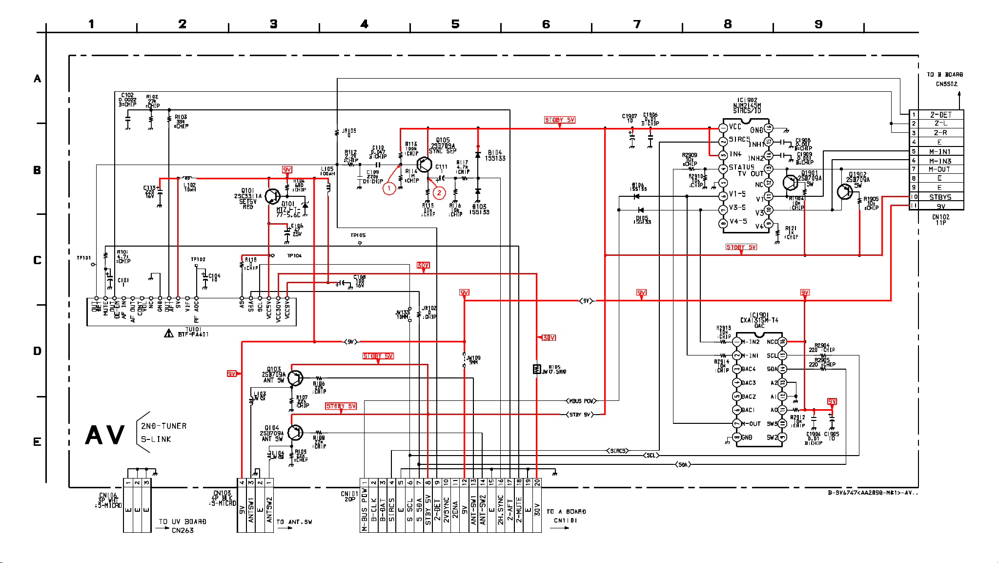
 Loading...