

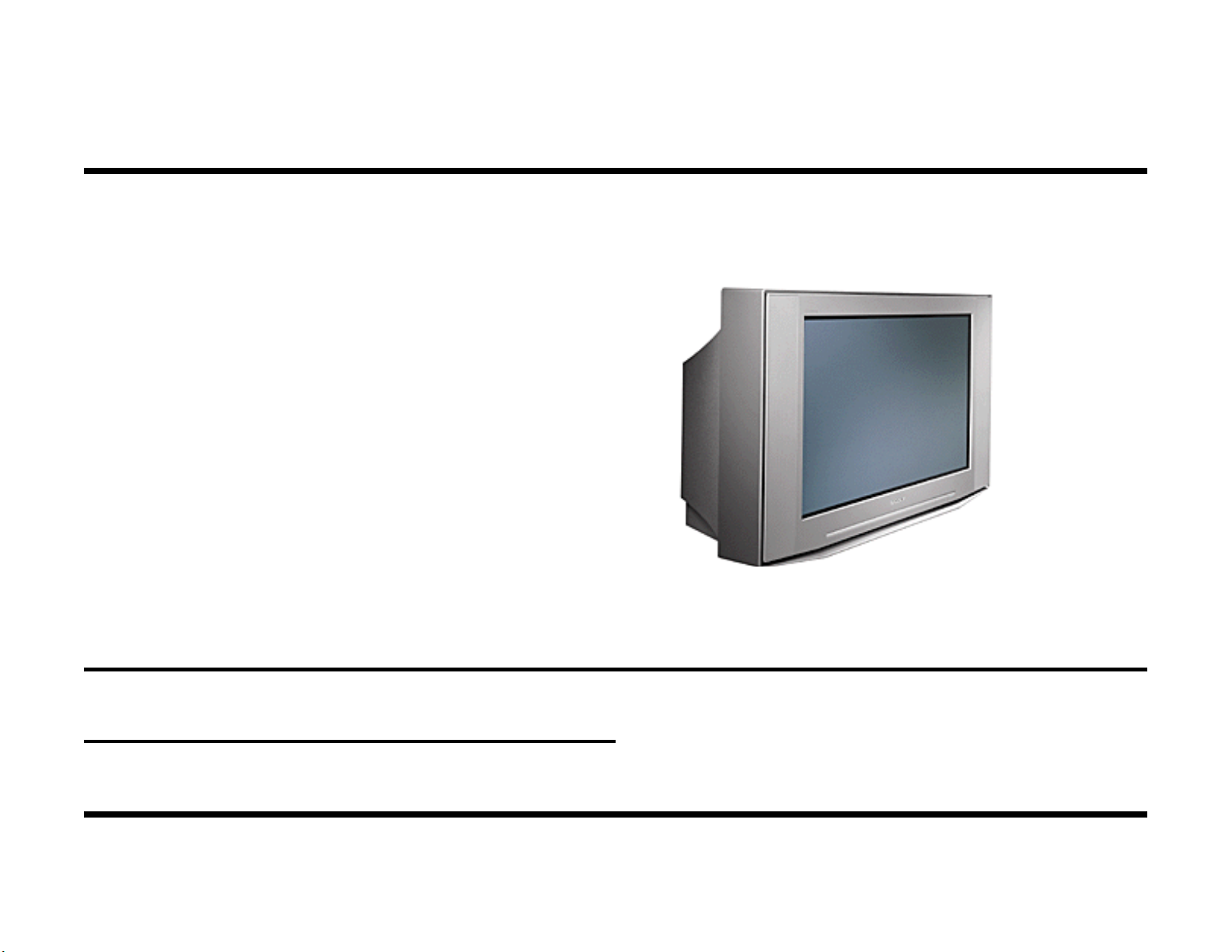
Sony KV-32XBR400,KV-36XBR400 Training Manual
S®
Direct View
Television
DX-1A Chassis
Models: KV-32XBR400
Training Manual
KV-36XBR400
Circuit Description and Troubleshooting
Course: DTV-02

Table of Contents
Introduction 2
DTV Converter Boxes 3
USA Analog Transmission Format 3
USA Digital Transmission Formats 5
Digital TV (DTV) Converter Boxes 5
New Features 9
Overall Block 11
SD to HD Conversion Concept 15
Video Block 21
Picture with Picture 27
Power ON Block 29
Power Supplies 29
Standby Power Supply 29
Primary & Secondary Power Supplies 29
Primary Power Supply 31
Start Up 31
Regulation 31
Testing 33
Testing 35
Horizontal Drive / H Pincushion Correction /
Filament Voltage 37
Basic Horizontal Drive Circuit 37
PMW Circuit 37
Filament Voltage 39
G2 Circuit 41
HV Converter Block 43
Start Up 43
Protection / Shutdown 43
HV Adjustment 43
Testing 45
Communications 47
Dynamic Focus Block 51
Static Focus Concept 51
Dynamic Focus Concept 51
Circuitry 51
Adjustment 55
DQP Circuit Corner Focus Correction 57
Secondary Power Supply 35
Start Up 35
Regulation 35
Convergence Circuit 61
Concept 61
Circuitry 61

Adjustment 61
Appendix
Picture Tilt Correction 63
Vertical Pincushion Correction Circuit 65
Concept 65
Adjustment 65
Vertical Process 67
Audio Block Diagram 71
Features 71
Signal Path 71
Self Diagnostic Block 73
Self Diagnostic Circuit 75
Service Mode Display i
Digital Satellite System Converter Box ii
DTV Set Top Box iii
IEEE-1394 iv
DX-1A Chassis Assembly vii
Board Replacement viii
HV Adj. check Bulletin 492 ixi

1
NOTES
Introduction
g
This model KV32XBR400 is a high resolution TV designed to bridge the
gap between the current analog TV sets and the forthcoming high definition digital TV (HDTV) sets. This set can accept the current standard
resolution NTSC TV transmissions, DVD, VHS, and Camcorder video signals, convert them, and display them on a high-resolution TV screen. An
external set top converter box is necessary to receive Digital TV programs.
Related Models
DX-1A TV Chassis Models
Model Screen size Aspect
Ratio
KV32XBR400 32 diagonal 4:3 $1999.99
KV36XBR400 36 diagonal 4:3 $2499.99
Higher Resolution Inputs
This TV can also accept standard resolution 480p or high resolution 1080i
video signal formats from an external HDTV, satellite, or cable converter
box as component video (Y, Pb, Pr) inputs. These 480p and 1080i signals can have a wide 16:9 aspect ratio. If they do, the display will be in
letterbox format with black above and below the picture on the 4:3 aspect
ratio picture tube of these TV sets.
Only the Digital TV’s 720p resolution video format cannot be displayed on
this set. The picture will not be synchronized.
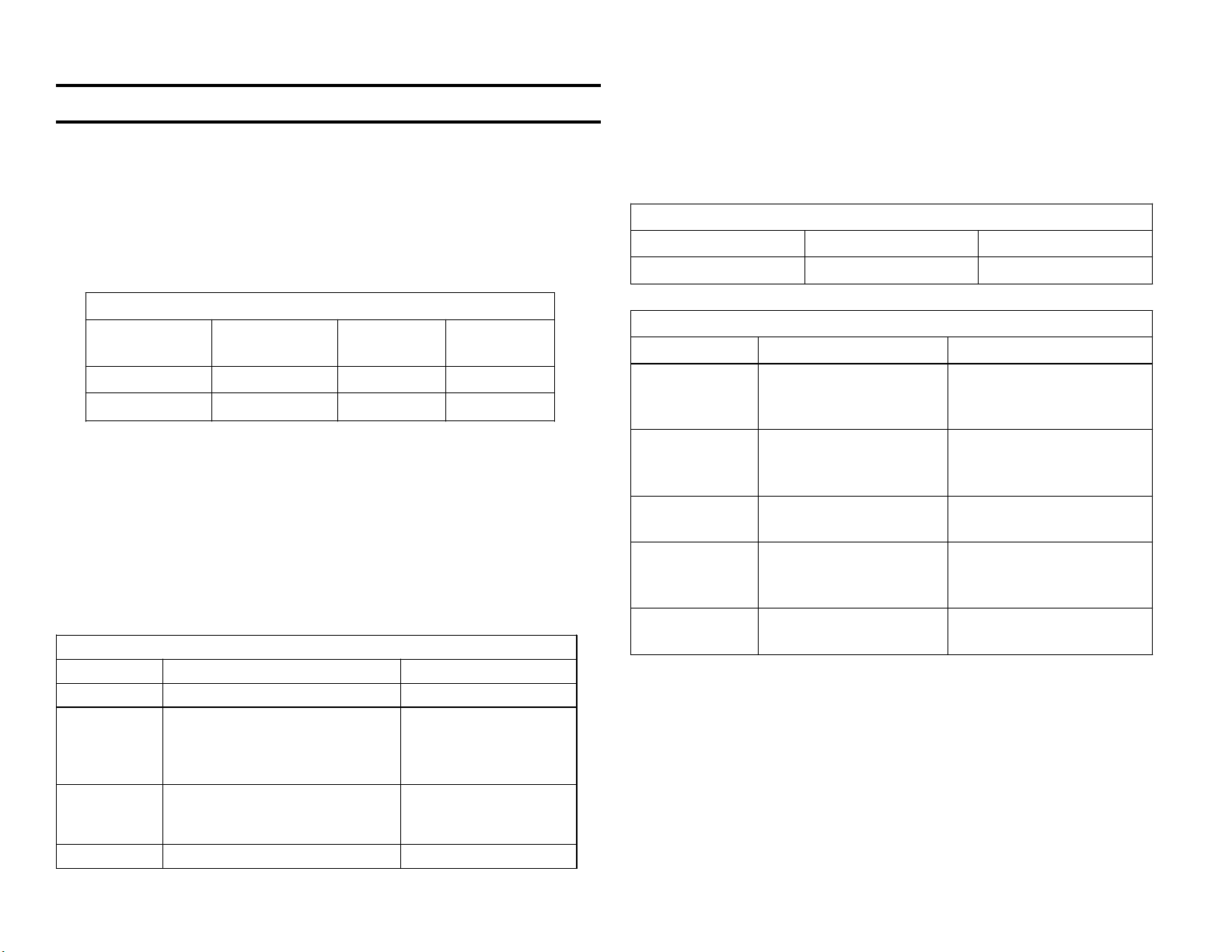
KV32XBR400 / KV36XBR400Inputs
Name Format Source
RF NTSC VHF, UHF, Cable
Video 1-4 +
Stereo
jacks
Video 5-6 +
Stereo
Jacks
Control S Sony Audio Equipment
S or Composite video:
Standard resolution 480
interlaced lines (480i).
Component video: Standard
Resolution 480i, 480p or
h Resolution 1080i format
Hi
Video tape recorder,
camcorder, DVD
player, TiVO
recorder
DTV, Satellite, or
Cable Converter box
MSRP
Circuitry Information
The power consumption and self-diagnostics remain the same as other
Sony TVs. This set’s change to high-resolution video results in circuitry
changes to the video processing, horizontal frequency (fixed at 33.75kHz),
and high voltage generation.
Power Consumption at 120Vac
Snow Dark screen/video 1 Surge
1.2 A 1.1 A 6 A (degaussing)
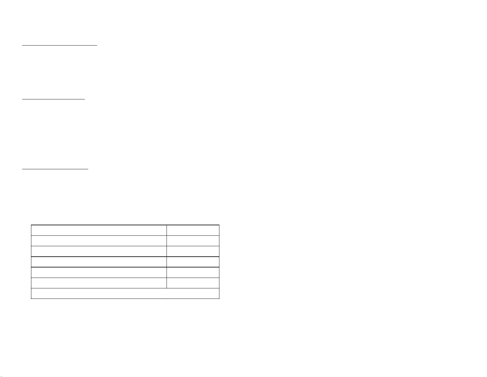
General Servicing Information
Item Location Comments
Self
Diagnostics
Filament
Voltage
High Voltage
Converter
G2 (Screen
adjustment)
Circuits on A & D
boards. Indicator on
front panel.
From 7V, A Bd
(Primary PS) and HOT
transformer, D Bd.
Standby/Timer LED
blinks to ID problem
area.
The CRT filament
voltage comes from 2
sources.
D board near flyback AFC signal from HOT
turns ON HV Converter.
On the CRT board Adjustment is in the
board replacement
guide (appendix).
Focus Control On the FBT Adjust for sharp picture
center and sides
Filament Voltage - This CRT voltage comes from two sources:
• Unregulated 7V supply from the Primary Power Supply on the A board
(used as a preheat).
• The HOT (horizontal output transformer) after a 6Vdc regulator on the
D board (main filament voltage supply).
High Voltage Generation - An independent HV oscillator circuit with a
special high frequency flyback transformer regulates the HV to 31.5kV.
The HV converter stage is turned on only after the Horizontal drive signal
from the HOT is detected.
2
3
DTV Converter Boxes
In order to compare converter box specifications you need to understand
how resolution is measured in the interlaced and progressive scan methods. With this information you can also determine which one of the 18
digital formats offers better resolution.
Resolution
The two most popular methods of measuring picture resolution are in
pixels (dots) or in lines. Incremental dots called pixels are often associated with monitors. Lines of resolution is a measurement for TVs. In the
monitor specifications, the number of vertical pixels is listed first. In the
TV specifications, the number of horizontal lines is listed first. For these
examples of specifications, a high-resolution monitor and (digital) TV standard were chosen:
Monitor
Spec
1024
1024 x 1800 pixels
X
1800
picture is not seen and the picture is normally over-scanned (larger than
the TV screen). Therefore, the TV resolution is said to be “480” (horizontal) lines instead of the transmitted 525 lines.
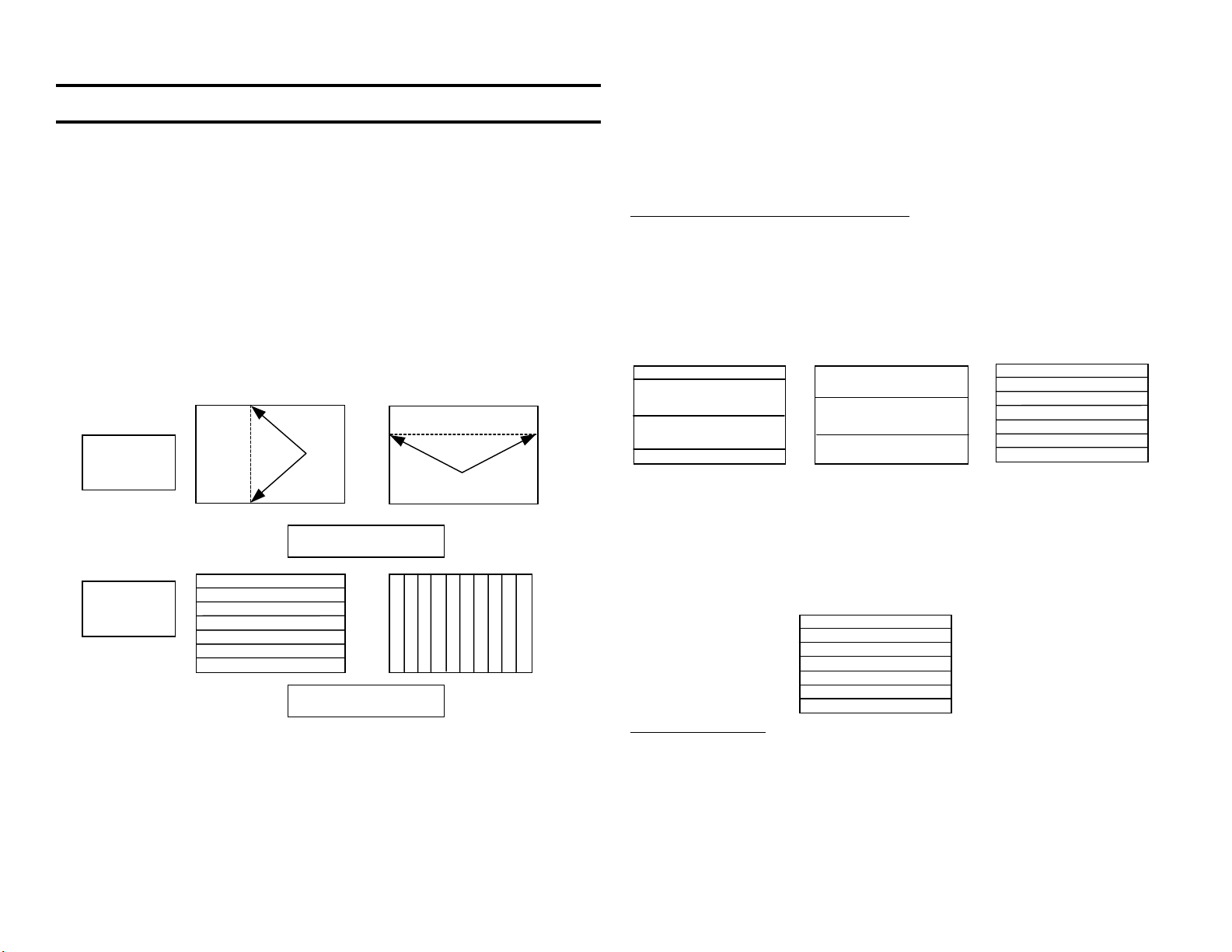
USA Analog Transmission Format
Interlaced and Progressive Scanning
In the NTSC television transmission format a complete picture (frame)
consists of two pictures (fields) interlaced together. Each half picture is a
field of 262.5 scanned lines. Therefore a complete picture is 262.5 x 2 =
525 lines. The two scanned fields are interlaced so the second field of
262.5 lines fits in-between the first field.
Interlaced Scan
Field 1
If a picture is not interlaced, it is a progressive scan image (not NTSC
format). This means the entire picture frame is presented in the first scan
and a second picture is presented in the second scan.
+
Field 2 = Frame
TV
Spec
1080 x 1920 lines
X
Although the semantics are different (vertical pixels/horizontal lines), the
first number in both specifications is the maximum number of black to
white transitions that can occur as you count from the top of the screen to
the bottom.
In the current NTSC (National Television Standards Committee) TV transmission standard, 525 horizontal lines are transmitted but only about 480
lines are visible. This is because the vertical blanking area above the
Progressive Scan
Field 1 =
Frame
30 or 60 Frames?
In the NTSC standard the first field takes 1/60 second to scan a screen of
262.5 lines. Then a slightly smaller vertical sync pulse in the second field
is created and the second picture field is shifted lower than the first to fit
in-between. The second field also takes 1/60 sec., completing the entire
picture frame in 1/60 + 1/60 = 2/60 sec = 1/30 sec.
(
)
y
g
DTV Set Top Converter Boxes (as of July, 2000
)
RF Inputs
Ch 1-125 Cable DTV *
Ch 1-99 Digital TV
Ch 2-69 Analog TV
Video Output
Standard Resolution High Resolution
Small dish Satellite
Audio Output
Format (# Horiz lines)
Analog
Di
ital
RF(Ch 3/4)
Mfg. Model
RCA DTC-100 X X X X X X X VGA 1080i/540p X X
Panasonic TU-HDST50 X X ? X X X 720p X X
TU-HDS20 X X X X ? X X X BNC ? X X
Pioneer SH-DO7 X ? X 1080i *** X X X
SH-D505 X X ? X X X BNC 1080i/ X X X
Mitsubishi SR-HD400 X X X X X X X X ? X X
SR-HD500 X X X X X X X X ? X X
Sony DTR-HD1 X X X phono 1080i X X
SAT-HD100 X X X X X X VGA 1080i/480p X X
Sharp TUDTV1000 X X X X X VGA/ 1080i/480p X X X
Proscan PSHD105 X ? ? X X X X VGA 1080i/540p X X
Samsung SIRT100 X ? ? X X X X ? 1080i/480p X X
Comp Video
S Video
Y, Pr, Pb
RGB,H,V **
720p/480p
BNC
L & R
IEEE 1394
Optical
Coax
* DTV must be 8VSB modulation
X = Yes ** VGA = computer monitor jack (15 pin D type)
? = insufficient information BNC = BNC connectors, one for each of the signals
blank = No *** Connection to Pioneer model PRO-700HD TV onl
like terrestrial ATSC DTV transmissions
.
4
5
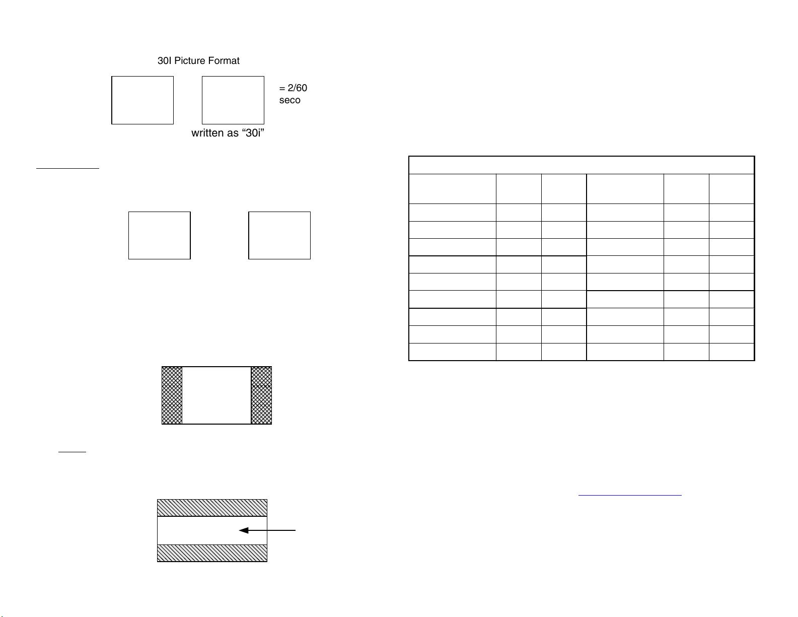
30I Picture Format
1/60 sec.
Field 1
+
1/60 sec.
Field 2
= 2/60
second or
1/30
The NTSC format is commonly written as “30i” picture format because it
takes 1/30 of a second to complete an interlaced picture.
Aspect Ratio
Although the first pictures were round, later TV pictures adopted a rectangular shape. The aspect ratio of these pictures is the same as they are
today, 4 x 3 ratio.
3
4
16
9
Movie theaters show films in a wider 16x9 aspect ratio. This 16x9 picture
is also the way most films are shot. To present the original 16x9 picture
on a 4x3 TV screen, one of two common methods is adopted to fit the
picture:
In method 1, the 16x9 picture is cropped or cut off at the left and right. The
main action part of the picture (usually the center or near center) is the
only part transmitted.
Shaded
area
Cropped/
removed
Method 1
Cropping
Center
of 16 x 9
picture
USA Digital Transmission Formats
There are 18 digital transmission formats approved by the ATSC (Advanced Television Standards Committee) in the USA. The first six offer
HD (high definition/resolution) signals in a 16x9 aspect ratio. The remaining 12 formats are SD (standard definition) signals in progressive (p) or
interlaced (i) scan. Note that the 480p signal can be a 4:3 or 16:9 aspect
ratio transmission.
18 Digital Transmission Formats
Resolution
Aspect
Frame Resolution
Ratio
1. 1080x1920 16:9 30 i 10. 480x 704 16:9 24 p
2. 16:9 30 p 11. 4:3 60 p
3. 16:9 24 p 12. 4:3 30 i
4. 720 x 1280 16:9 60 p 13. 4:3 30 p
5. 16:9 30 p 14. 4:3 24 p
6. 16:9 24 p 15. 480x 640 4:3 60 p
7. 480x 704 16:9 60 p 16. 4:3 30 i
8. 16:9 30 i 17. 4:3 30 p
9. 16:9 30 p 18. 4:3 24 p
A standard definition transmission contains less data, permitting space
for another digital video stream to coexist on the same frequency (channel). Therefore, a station can have more than one program stream on a
digital channel. The maximum number of programs is six.
Aspect
Ratio
Frame
In method 2, the 16x9 picture is shrunken and placed on the TV screen.
The
entire picture is seen but with black areas above and below the picture. This method of viewing the entire 16x9 picture on a 4x3 set is called
a Letterbox picture. Letterbox pictures can be selected on some DVD
players and TV sets from the menu if the DVD or TV transmissions offer
it.
Entire
16x9
Picture
Method 2
Letterbox
Digital TV (DTV) Converter Boxes
TV broadcasters are transmitting their analog signals on one channel and
their DTV signals on another. A list of their analog and digital channel
assignments by state is located at www.transmitter.com.
To receive a DTV station on an analog TV, a set top converter box is
used. The box receives digital RF and outputs analog composite video to
the TV. The boxes can also output higher resolution video signals to a
high-resolution analog TV. These cable boxes are flexible at their input
and outputs:
RF inputs:
Channels 1-99 Digital TV
The TV converter boxes listed in the chart all decode DTV signals from off
the air (terrestrial) in the USA and Canada. These TV stations conform to
the DTV ATSC format that approves an 8VSB modulation method. The
new digital channel numbers are frequencies within the current analog
Channels 2-69.
Ch 1-125 Cable DTV
At this time some cable TV companies are providing DTV service using
8VSB modulation and other cable companies sell DTV service using QAM
modulation. The 8VSB modulation means this method is probably the
same as the off the air ATSC (DTV) signal. This means if the DTV converter boxes can receive the cable band, they can decode the cable DTV
signal. Cable companies using a QAM (Quadrature Amplitude) Modulation method require their DTV boxes for processing.
950-1.45GHz Satellite
In competition with cable companies are Direct Broadcast System (DBS)
companies that provide satellite TV channels. The larger analog signal
DBS dishes that operate on the ”C” band were not as popular as the
smaller “Ku” band digital signal dishes. A satellite manufacture can either
provide the TV service directly to the consumer, rent transponders (space)
to other providers, or both. Some of the larger companies are:
Satellite Manufactures Providers
GM Hughes Electronics
EchoStar/Dish Network (HD 1080i) Direct TV
DBSC (Direct Broadcast Satellite Corp) PrimeStar
Direct Sat
A few converter boxes can receive digital satellite signals. This combination of DTV and satellite decoding in one box is feasible because the
decoding circuitry is similar. It is uncertain if these converter boxes can
decode the new satellite high definition DTV signals.
Video Outputs
The converter boxes output standard resolution and high-resolution signals. All the boxes can down convert a 1080, 720 or 480 line input signal
into a standard resolution 480i picture for an analog TV. This standard
resolution output comes from the S or composite video jacks of the box.
For the higher resolution TVs that are coming out now, there is a component (Y, Pr, Pb) and/or RGB output from the box. The RGB +sync output
could be five individual BNC jacks or a single VGA connector, such as the
ones found on the back of a home computer for its monitor.
After the correct mechanical connection is made, the signal format from
the box must match that of the high resolution TV. The box’s output
signal formats are menu selectable for box to TV compatibility. For example if the TV accepts 1080i signal format, the box’s output must correspond with the same output signal format.
If a 1080 format DTV signal is received, the box will convert it from an RF
signal, unscramble it, separate the audio, video and data, and then
uncompress the audio and video. The video will be changed into component video or RGB voltages that are input to the TV. The sync is on the Y
line in the component video signal.
If a standard resolution 480 format DTV signal is received, the same signal processing occurs but there is an additional scan converter to double
the information before leaving as a 1080i format signal for the hich scan
TV.
Tempo
ACC (advanced Communications Corp)
Satellite reception is vulnerable to rain scattering the signal and the sun’s
microwave energy overpowering the satellite signal. The solar outages
may occur only for minutes during the time span of a week or two during
the spring and fall equinoxes. At these times the sun is behind the target
satellite adding noise to the signal.
Audio Outputs
All the converter boxes have composite video output and corresponding
analog audio L&R channel outputs. Some boxes have digital optical and/
or coax outputs for a Dolby
converter box has an IEEE 1394 output for decoding the signal in a SVHS
AC-3 decoder (often in a receiver). One
6

recorder. The IEEE-1394 format is also called i.LINK, or Firewire ”
because of the convenience or high speed. Customarily, both video and
audio is sent on this 4-wire cable. More about the IEEE-1394 format is
found in the appendix of this book.
Dolby is a registered trademark of Dolby laboratories.
Fire Wire is a trademark of Apple Computer Inc.
i.LINK is a trademark of Sony.
7

NOTES
8
9
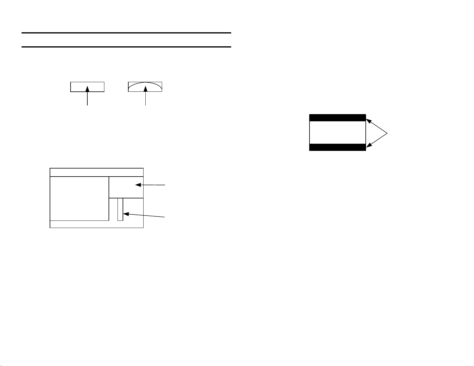
New Features
FD Wega Picture Tube
The Sony flat screen picture tube is a full flat screen inside and outside.
Sony
FD
Glass
screen
Electron beam
Favorite Channel Preview
Pressing the Favorites remote button reduces the main picture and displays a small picture of another (favorite) station. As you move the joystick down the list of numbers, the preview picture changes to that station.
Select that station by pressing enter.
Favorite Channel Display
Main Pix
Non-Sony
Picture Tube
Preview
Channel Numbers
Parent Menu
This allows the owner to block TV programs according to their content.
Entering the owner’s four-number password enables viewing of the blocked
programs. The owner’s password can be cleared with the master password 4357 (“HELP”). The owner’s password can also be reset from the
service mode by pressing 8, then enter.
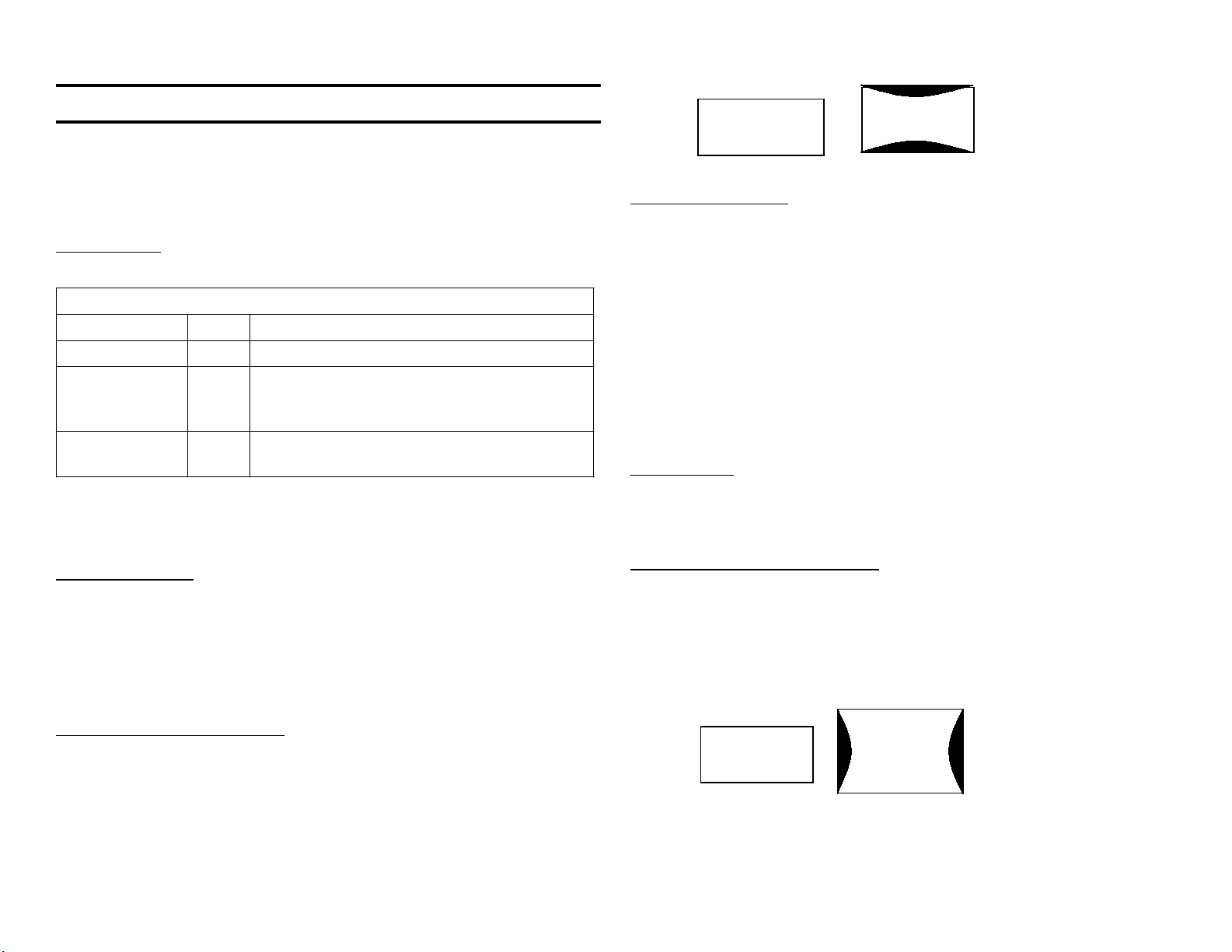
Set Up Menu - 16:9 Enhanced
A 480p input signal can be in 4:3 or 16:9 video format.
Letterbox
picture
16:9 Pix
The wide 16:9 video format produces a picture on a 4:3 picture tube that
is too tall. From the Auto/ON/OFF selections of the set up menu, choose
16:9 Enhanced = ON to reduce the vertical size of the picture so the
picture is the correct aspect ratio.
The “Auto” selection reduces the picture size if there is an ID-1 signal in
the vertical blanking area of the input signal. The ID-1 signal identifies the
video signal as 4:3 or 16:9 format. Sony 16:9 camcorders insert the ID-1
information into the video during recording.
Black
border
New Picture Mode = Pro
The basic video modes are Vivid for use in bright daylight, Standard for
reduced brightness in the home, and Movie for evenings. The Pro video
mode is new. This mode darkens the picture and centers its dark to bright
operating range for the widest dynamic picture swing. This mode is meant
for pro movie watchers in a darkened room where the subtle dark to gray
changes are made evident. The video settings (picture, brightness, color,
etc) can be changed in any mode.
Video Menu - DRC-MF
Select an Interlace or Progressive mode display from the Video menu
under “DRC-MF”. Interlace is selected when watching moving images.
The Progressive mode is selected only when many non-moving images
are displayed, such as text or a still photograph. Selecting the Progressive mode stops the flickering that occurs in an interlaced picture when
the two interlaced fields are not exactly the same. This interlace/progressive is not an option with a 1080i input

NOTES
10
11
Top & bottom
lines bowed in
(exaggerated)
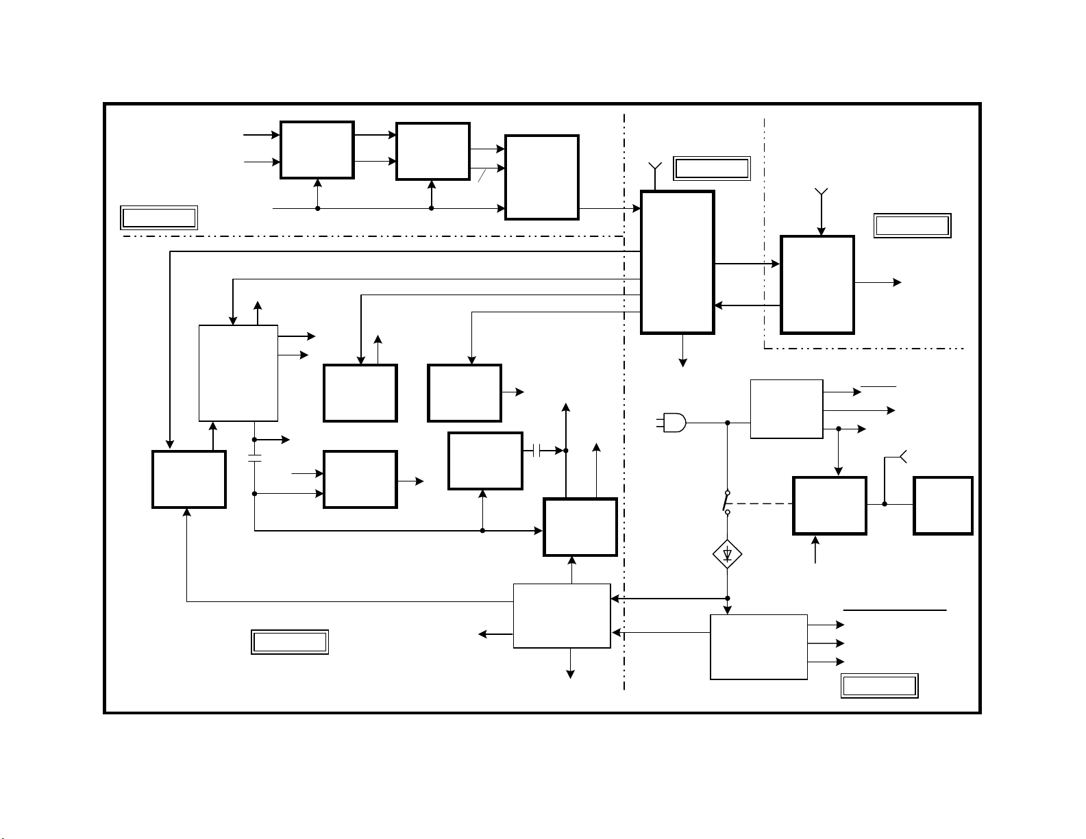
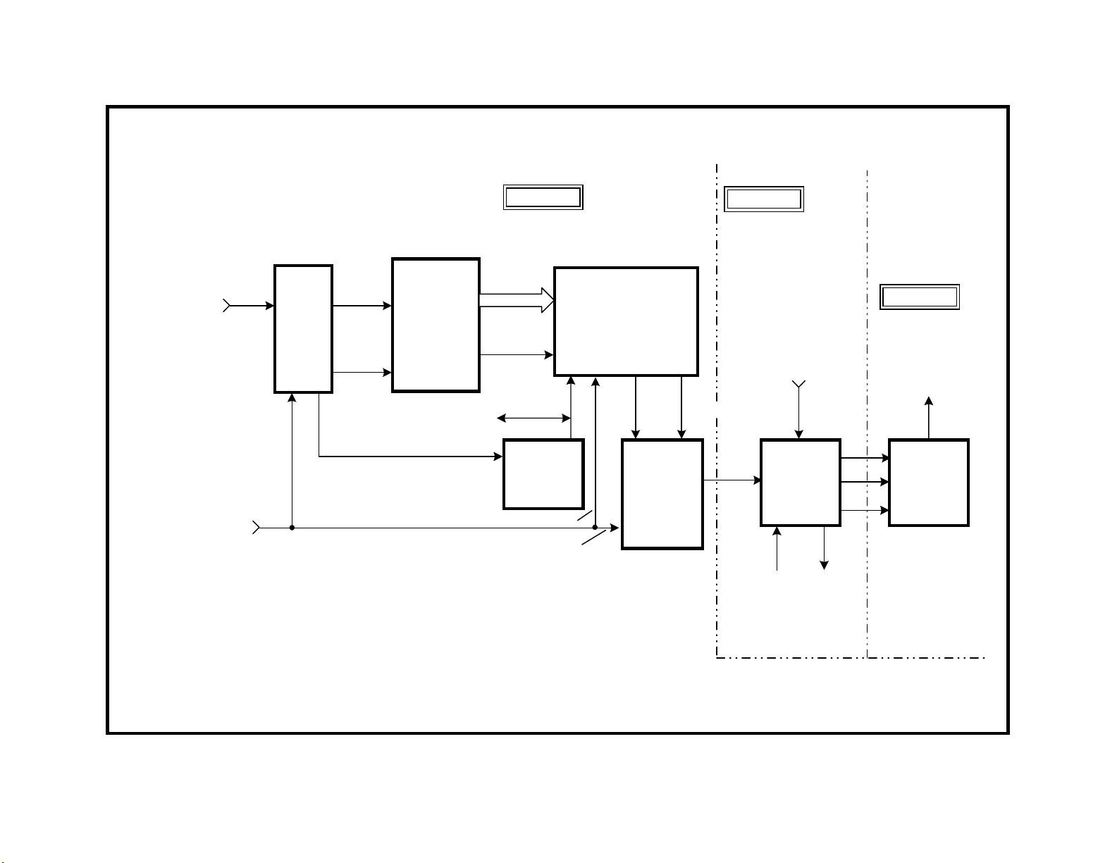
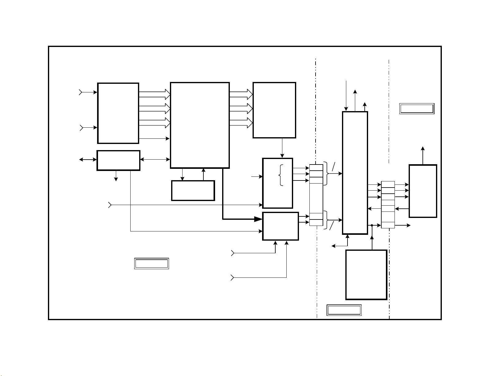
Overall Block
The only conventional block within this TV is the vertical block. The remaining blocks are different because this TV is a high-resolution type with
a “Wega”® flat screen. Therefore, changes to the power supply, horizontal frequency, convergence, focus, and video processing support the improved picture.
Power Supply
The power supply is in three parts to divide the load on the boards:
Power Supplies
Board Purpose
Standby A Outputs Standby 15V, 7V, & 5V.
Primary Power
Supply
Secondary
Power Supply
The Primary power supply starts the secondary supply using a Pri-Pre
15V line. Once the Secondary power supply operates, Main 9V outputs
to start the horizontal and vertical oscillators in Y/C CRT Drive IC201.
Vertical Deflection
In some Sony TV sets, there is no V Drive output the Y/C IC until data and
clock are input. Unlike these TV sets, this IC201’s vertical will output
when power is applied. The sync source is dependent upon whether
progressive, interlace or a sub picture is chosen. The vertical oscillator
output is amplified by IC5004 on the “D” deflection board to drive the DY
deflection yoke.
A Outputs Set 9V, Set 5V, & Set 3.3V to local
parts on the A, B, & BD boards. Outputs
Pri-Pre 15V to start the Secondary PS.
D Outputs +200V, +135V, +24V (audio), Main
12V, Main 9V, & Main 5V to the D board.
V Pin
Distortion
Horizontal Deflection
The higher 33.75kHz horizontal frequency is made by IC201 and fed to
the H Drive/Output stage on the D board. The output stage is fed regulated voltage from the +135V Secondary power supply via the PWM circuit of IC5002.
The horizontal drive stage not only supplies the H Deflection yoke (H DY)
with scan voltage, but also supplies G2 and filament voltage for the CRT.
A regulated +200V is also output to supply the RGB output amplifiers on
the C board.
Horizontal AFC pulses from this stage are needed by the convergence
and dynamic focus stages for sync. The AFC pulses are used to start the
HV Converter.
HV Converter
Regulated HV and focus voltage is made by the HV Converter stage. It
uses +200V from the secondary power supply to run and AFC pulses
from the horizontal deflection stage to start.
Horizontal Pincushion Correction
To keep the lines at the left and right of the screen straight, an east/west
(E/W) H pincushion correction signal is made in IC201. The E/W signal is
used to modulate the PWM IC5002 that controls picture width. By changing the width line-by-line, the left and right sides in the large picture can be
straightened.
Vertical Pincushion Correction
As the TV screen becomes larger, the yoke can not perfectly control the
beam at the screen perimeter. An additional coil on the top and bottom of
the CRT neck assembly is fed V Pin correction signal from IC201 and
IC5514. The additional coil eliminates any minor inward/outward bow at
the top and bottom of the picture.
H Pin
Distortion
Sides bowed in
(exaggerated)
B BD.
+135V
TUNERS
VIDEO 1-4
VIDEO 5-6
E/W
Q5026-8,
Q5035-6,
H DRIVE
H OUTPUT
IC5002
PWM
Q5030
100V
IC3048
SW
480i
H DRIVE = 33.75kHz
CRT
FILAMENT
200V
C BD.
G2
IC5514
V PIN
OUT
H
DY
VTIM
IC5513,
IC5515
CONV.
AFC
D BD.
VID
SYNC
COIL ON
IC3303/
IC3408
DRC/MID
480p
VPIN
CRT
NECK
CY
DY
SYNC
1080i
IC5004
V OUT
IC5511
DF/DQP
COILS
IN
+
15V
-
MAIN VOLTAGES
12V,9V,5V,24V
IC3414
SW
V DRIVE
V
FOCUS
DY
HV
IC8002
HV
CONV.
200V
SECONDARY
P.S
MAIN
9V
IC201
Y/C
CRT
DRIVE
VTIM
(IC5513)
340VDC
PRE
15V
A BD.
D6530
RGB
IK
STANDBY
PRIMARY
P.S
IC9001-3
RGB
OUT
IC701
MAIN
uCOM
POWER
ON
+200V
(HOT)
C BD.
CRT
CATHODES
STBY
15V
7V
5V
IC5501
(D BD.)
SET VOLTAGES
9V
5V
3.3V
A BD.
NVM
IC707
NVM
OVERALL BLOCK
12
48DTV02 1273
19/2/00

13
Convergence of the Three Beams
The good news is that the complex convergence signal is made in one
IC5513 and the signal is amplified in the second IC5515. The output
signal drives a convergence yoke inside the main horizontal and vertical
deflection yoke. The convergence stage affects the beams at the perimeter of the screen.
Dynamic Focus Correction
As a beam is deflected, the points of focus form a curve. The focus points
have to be moved to match the flat screen of the TV. A signal from DF
IC5511 modulates the DC focus voltage to prevent poor focus at the left
and right sides of the screen.
Video Processing
Standard Resolution Input – A standard resolution NTSC signal can be
selected from either tuner or any video input. However, this high resolution TV runs at a different horizontal frequency of 33.75kHz. To accept a
standard NTSC signal (480i) that runs at 15,734 Hz, the video signal is
improved and the horizontal sync more than doubled.
The Digital Reality Creation Circuit (IC3303) analyzes each pixel of a line
to add another line. Therefore the DRC circuit doubles the number of
video lines of a standard NTSC signal. The DRC also doubles the horizontal sync frequency before passing the signal onto the MID circuit on
the same board.
High Resolution Input - Video inputs 5 and 6 are for Y, Pr and Pb component signals only. They can be standard (480i) or high resolution (480p or
1080i). The 480p signal is already high resolution at double the H freq so
it need not go through the DRC circuit. It is switched directly into the MID
circuit.
The high-resolution 1080i picture is at the same horizontal frequency as
the TV set (33.75kHz), so it does not go into the DRC or the MID circuit.
The 1080i signal is switched directly to the Y/C CRT Drive IC201 on the A
board.
Since the 1080i signal is a wide 16:9 ratio picture, it looks squeezed in on
a 4:3 aspect ratio picture tube. To make the picture look correct, the
vertical can be reduced using a “16:9 enhanced” menu command. Vertical reduction can be automatically done if there is a code in the vertical
blanking area of the input signal called ID-1. This signal identifies the
aspect ratio of the picture.
The Multi Image Driver (MID) Circuit (IC3408) stores the lines and outputs the signal based on a new horizontal frequency that matches the TV.
At the higher frequency, the picture finishes before the scan. Blank lines
are added as filler by this MID stage before leaving the board.

B BD.
+135V
TUNERS
VIDEO 1-4
VIDEO 5-6
E/W
Q5026-8,
Q5035-6,
H DRIVE
H OUTPUT
IC5002
PWM
Q5030
100V
IC3048
SW
480i
H DRIVE = 33.75kHz
CRT
FILAMENT
200V
C BD.
G2
IC5514
V PIN
OUT
H
DY
VTIM
IC5513,
IC5515
CONV.
AFC
D BD.
VID
SYNC
COIL ON
IC3303/
IC3408
DRC/MID
480p
VPIN
CRT
NECK
CY
DY
SYNC
1080i
IC5004
V OUT
IC5511
DF/DQP
COILS
IN
+
15V
-
MAIN VOLTAGES
12V,9V,5V,24V
IC3414
SW
V DRIVE
V
FOCUS
DY
HV
IC8002
HV
CONV.
200V
SECONDARY
P.S
MAIN
9V
IC201
Y/C
CRT
DRIVE
VTIM
(IC5513)
340VDC
PRE
15V
A BD.
D6530
RGB
IK
STANDBY
PRIMARY
P.S
IC9001-3
RGB
OUT
IC701
MAIN
uCOM
POWER
ON
+200V
(HOT)
C BD.
CRT
CATHODES
STBY
15V
7V
5V
IC5501
(D BD.)
SET VOLTAGES
9V
5V
3.3V
A BD.
NVM
IC707
NVM
OVERALL BLOCK
14
48DTV02 1273
19/2/00
15
In a single scan
=
12i Interlaced scan
picture is 6 lines per field
6p Progressive
scan picture
1
2
3
4
5
6
SD to HD Conversion Concept
This TV has features designed to bridge the gap between the current
analog sets and newer higher resolution digital TV sets. The KV32XBR400
TV is a high resolution set capable of receiving the current standard definition (SD) NTSC signal. The NTSC standard resolution of 480i lines is
upgraded to a 960i (interlaced) or 480p (progressive) line picture, to be
compatible with this TV. The user selects interlaced scan if there is motion in the picture or progressive scan if there is a still picture signal in
order to stop interlace flicker. A higher resolution (480p or 1080i) signal
that does not need to be upgraded can be input to video 5 or 6 for advanced placement in the video chain.
Interlaced or Progressive Scan
Most technical people do not know how many horizontal lines are present
on the screen in a single scan from the top of the screen to the bottom.
The confusion about the number of lines shown at one time relates to the
different interlace/progressive scan modes.
In the progressive scan mode the entire picture is presented in one scan
of the picture tube (left to right, top to bottom). In an interlaced scan the
entire picture consists of two fields so the picture is presented in two
scans of the picture tube. The second field is displaced from the first so
the lines fit in-between each other making the completed picture:
Field 1 Field 2
number of lines in the total picture. The i suffix identifies an interlaced
picture. Since the picture is interlaced, there is only half the number of
lines presented in a single scan. In this case, there are 240 lines displayed in a single scan. This is equivalent to a 240p picture that displays
240 lines in a single scan (480i is the same as 240p).
Similarly a 480p picture is like a 960i picture because both these pictures
present 480 horizontal lines per scan. This is important to understand as
the standard resolution NTSC picture is changed to a higher resolution in
the “DRC” video processing stage of this TV.
Standard Definition Video Input
The Tuner and Video 1-4 inputs accept only the NTSC 480i-line standard
definition signal identified by the 15.75kHz horizontal frequency. The 480i
input signal is interlaced (i), consisting of two 240-line fields presented/
scanned one at a time that total the 480 lines. Therefore a 480i NTSC
picture normally displays 240 lines each time the picture is scanned. The
NTSC signal passes through the DRC and MID circuits.
The resolution of the TV picture is measured in horizontal lines of a complete picture followed by the letter for the type of scan (i or p). For example, the NTSC signal contains 525 horizontal lines. The number of
viewable lines is reduced to 480 because of the time required for V & H
retrace, creating a blanking area above and below the picture. Therefore
the standard resolution NTSC signal displays a 480i picture. 480 is the
"6i" Interlaced Picture consisting of
alternating lines from fields 1 & 2
DRC Circuit
In this model KV32XBR400 high resolution TV, a single scan must contain 540 lines, more than double of a NTSC signal. The DRC circuit almost bridges the gap between the 240 line input signal and the 540 line
TV requirement. The DRC circuit doubles the number of horizontal lines
by analyzing the pixel data to construct new lines. Therefore the DRC
circuit brings the total line count from 240 to 480. The DRC circuit also
doubles the horizontal frequency to 31.5kHz to support these lines.

TUNER/
VIDEO
1-4
STANDARD
NTSC
RESOLUTION
480i
IC3048
SW
Y, Pb,
Pr
H + V
SYNC
IC3303
DRC
CIRCUIT
IIC
BUS
B BD.
Yo -7
Cr-7
Cb-7
H + V
DATA/CLK
IC3408,
IC3410
MID-XA
CIRCUIT
Y, Pb,
Pr
CONT
A BD.
IIC
BUS
C BD.
CRT
CATHODES
DATA/
CLK
VIDEO 5
VIDEO 6
480i
480p
1080i
480i
IC3603
VIDEO
ID-1
DECODE
480p
1080i
SD TO HD CONVERSION CIRCUIT
16
IC3414
YUV
SWITCH
DRIVE
OSD
IC201
Y/C
CRT
VERT
OUTPUT
IC5004
(D BD.)
IC9001-3
RGB
OUTPUT
12DTV02
10/2/00
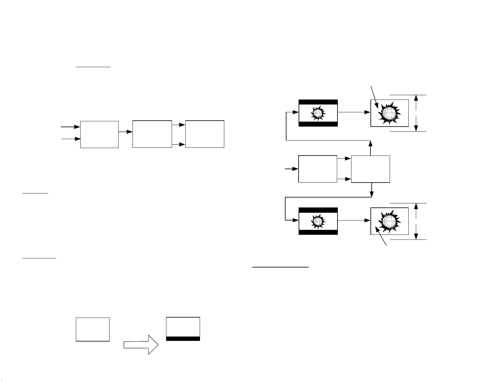
Progressive Scan - In this example of the progressive scan video processing, an NTSC still picture signal is input from a DVD player (in pause).
The user chooses progressive scan from the menu to reduce picture flicker.
Flicker occurs in an interlaced picture when the two fields are not exactly
the same images. The flicker is more noticeable in the movement area(s)
of the picture where the fields are different.
In the progressive scan mode the DRC circuit doubles the number of lines
from 480i (actually 240 lines) to 480p to make the NTSC signal compatible with the TV.
Tuner
Video 1-4
A/V
Switches
DRC
circuit
480i
Progressive or
interlaced output
480p
MID
circuit
960i
Interlace Scan - In a second example of the video processing, an NTSC
signal with live pictures is input from an antenna. The user chooses the
interlace scan mode from the menu because of the moving images. Each
interlaced field displays a slightly different transitioning picture making
movement seem smoother.
17
The MID circuit centers the picture by adding 30 blank lines above and
below the picture (60 lines total). This simple method permits the TV to
keep the vertical frequency at 60Hz. Therefore the MID circuit increases
the number of lines from 480p to 540p but these extra lines are blank.
There are still only 480 active (picture) lines.
480 active lines
540p
540 lines
Expand
Vertical
480p + 60 = 540p lines
480i
960i + 120 = 1080i lines
DRC
circuit
480p
960i
Progressive
MID Circuit
Interlaced
Adds 60
blank lines/scan
In the interlaced scan mode the DRC circuit still must double the number
of lines to meet the TV’s 480-line/scan requirement. The resolution is
changed from 480i (actually 240 lines) to 960i (actually 480 lines) by the
DRC circuit.
MID Circuit
Fortunately, the model KV32XBR400 TV’s horizontal deflection stage scans
at a 33.75kHz rate to display high definition (1080i) video signals. However The horizontal frequency output the DRC circuit is double that of
NTSC at 31.5kHz. This is slower than the KV32XBR400’s 33.75kHz rate.
Since the TV scans at a faster rate than what is input, the picture is finished faster, leaving blank lines at the bottom.
240/480
lines
15.75kHz/31.5kHz
480
lines
33.75kHz
1080 lines
Expand
1080i
Vertical
960 active lines (2 fields)
Vertical Expansion
To keep the 60 blank lines invisible, the vertical size is expanded slightly
(picture overscaned) so the 480 lines fill the 4:3 aspect ratio screen. This
is seen in the previous diagram where the 60 blank lines are shown (exaggerated) in black.

TUNER/
VIDEO
1-4
STANDARD
NTSC
RESOLUTION
480i
IC3048
SW
Y, Pb,
Pr
H + V
SYNC
IC3303
DRC
CIRCUIT
IIC
BUS
B BD.
Yo -7
Cr-7
Cb-7
H + V
DATA/CLK
IC3408,
IC3410
MID-XA
CIRCUIT
Y, Pb,
Pr
CONT
A BD.
IIC
BUS
C BD.
CRT
CATHODES
DATA/
CLK
VIDEO 5
VIDEO 6
480i
480p
1080i
480i
IC3603
VIDEO
ID-1
DECODE
480p
1080i
SD TO HD CONVERSION CIRCUIT
18
IC3414
YUV
SWITCH
DRIVE
OSD
IC201
Y/C
CRT
VERT
OUTPUT
IC5004
(D BD.)
IC9001-3
RGB
OUTPUT
12DTV02
10/2/00

19
High Definition 1080i
picture on the 4:3
aspect ratio
KV32XBR400 TV
16 : 9 ENHANCED (VERT REDUCTION)
High Definition Video Input
The Video 5 and 6 inputs can be standard or high definition format signals. The MID circuit distinguishes the video format by their horizontal
frequencies:
Video 5 or Video 6 Input Formats Horizontal Frequency
480i 15.734kHz
480p (4:3 aspect ratio) 31.50kHz
480p (16:9 aspect ratio) 31.50kHz
1080i (16:9 aspect ratio) 33.75kHz
480p Picture Process
A high-resolution 480p-video format is detected by its horizontal frequency
and selected by the MID circuit for video processing. The resultant picture appearance will depend upon whether the video format of the input
signal is a 4:3 or 16:9 aspect ratio.
4:3 aspect ratio - The MID circuit processes a 480p, 4:3 picture the same
as the 4:3 NTSC picture. The MID circuit adds 60 blank lines to the signals. The picture is normally overscanned so the 60 blank lines are not
seen.
480p
4:3 pix
MID
Circuitry
Adds 60
blank lines
16:9 aspect ratio - The MID circuit does have to add 60 lines to the 480p,
16:9 picture when the horizontal frequency is changed. When this 16:9
picture is placed on a 4:3 screen, the picture is too tall (screen width was
reduced).
To maintain the aspect ratio of the picture, the vertical size must be manually reduced so the picture looks normal on the TV’s 4:3 screen.
480p
16:9 pix
MID
Circuitry
540p
540p
4 : 3
Pix Tube
480 lines
Vert size
increased
540p
Vertical
size
reduced
1080i Picture Process
The 1080i-video format is a high-resolution picture with a 16:9 aspect
ratio at a 33.75kHz horizontal frequency. The 1080i picture actually has
540 lines/scan (half 1080). Although 540 lines would fill this picture tube
vertically, the picture tube is the wrong aspect ratio. The 16:9 picture is
the correct width on the TV, but is too tall because it is displayed on a 4:3
picture tube. To compensate, the vertical size is automatically reduced
when a 33.75kHz input signal is detected. The final 1080i picture is a
“letterbox” on the KV32XBR400:
Aspect Ratio Detection
The picture’s aspect ratio is always 4:3 for a standard 480i input and 16:9
for a 1080I input. Unfortunately a 480p signal can be in either aspect ratio
so the TV must be adjusted manually. The MID circuit monitors the horizontal frequency of the input signal when video 5 or 6 is selected. If the H.
input frequency is 15.734kHz or 31.5kHz, blank lines are added and the
picture is normally over-scanned vertically for a 4:3 picture. If the H. input
frequency is 33.75kHz, IC201’s (A board) vertical oscillator signal is amplitude reduced to maintain the correct aspect ratio for a 1080i, 16:9 picture on a 4:3 picture tube. Vertical reduction must be manually selected
from the user’s setup menu when a 480p 16:9 signal is input.
Picture Compensation using Horizontal Frequency
Resolution Aspect
Ratio
Horiz Freq Vertical
Compensation
Lines
added
480i 4:3 15.734kHz Normal Overscan Yes
480p 4:3 31.50kHz Normal Overscan Yes
480p 16:9 31.50kHz Manual Reduction Yes
1080i 16:9 33.75kHz Automatic Reduction No
TUNER/
VIDEO
1-4
STANDARD
NTSC
RESOLUTION
480i
IC3048
SW
Y, Pb,
Pr
H + V
SYNC
IC3303
DRC
CIRCUIT
IIC
BUS
B BD.
Yo -7
Cr-7
Cb-7
H + V
DATA/CLK
IC3408,
IC3410
MID-XA
CIRCUIT
Y, Pb,
Pr
CONT
A BD.
IIC
BUS
C BD.
CRT
CATHODES
DATA/
CLK
VIDEO 5
VIDEO 6
480i
480p
1080i
480i
IC3603
VIDEO
ID-1
DECODE
480p
1080i
SD TO HD CONVERSION CIRCUIT
20
IC3414
YUV
SWITCH
DRIVE
OSD
IC201
Y/C
CRT
VERT
OUTPUT
IC5004
(D BD.)
IC9001-3
RGB
OUTPUT
12DTV02
10/2/00
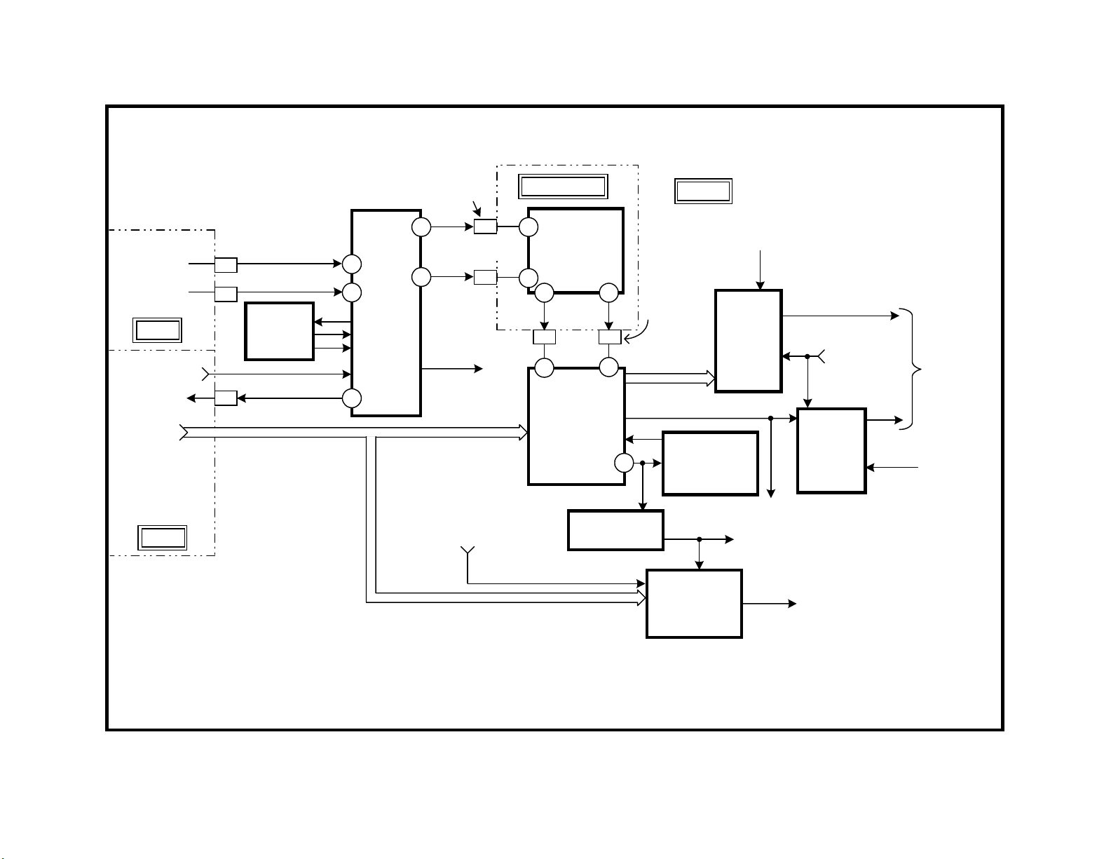
21
Video Block
This Video Block Diagram will show the video signal processing as it
changes from an NTSC composite video signal to separate Y & C, component Y, Pb, Pr and finally to RGB for the CRT cathodes.
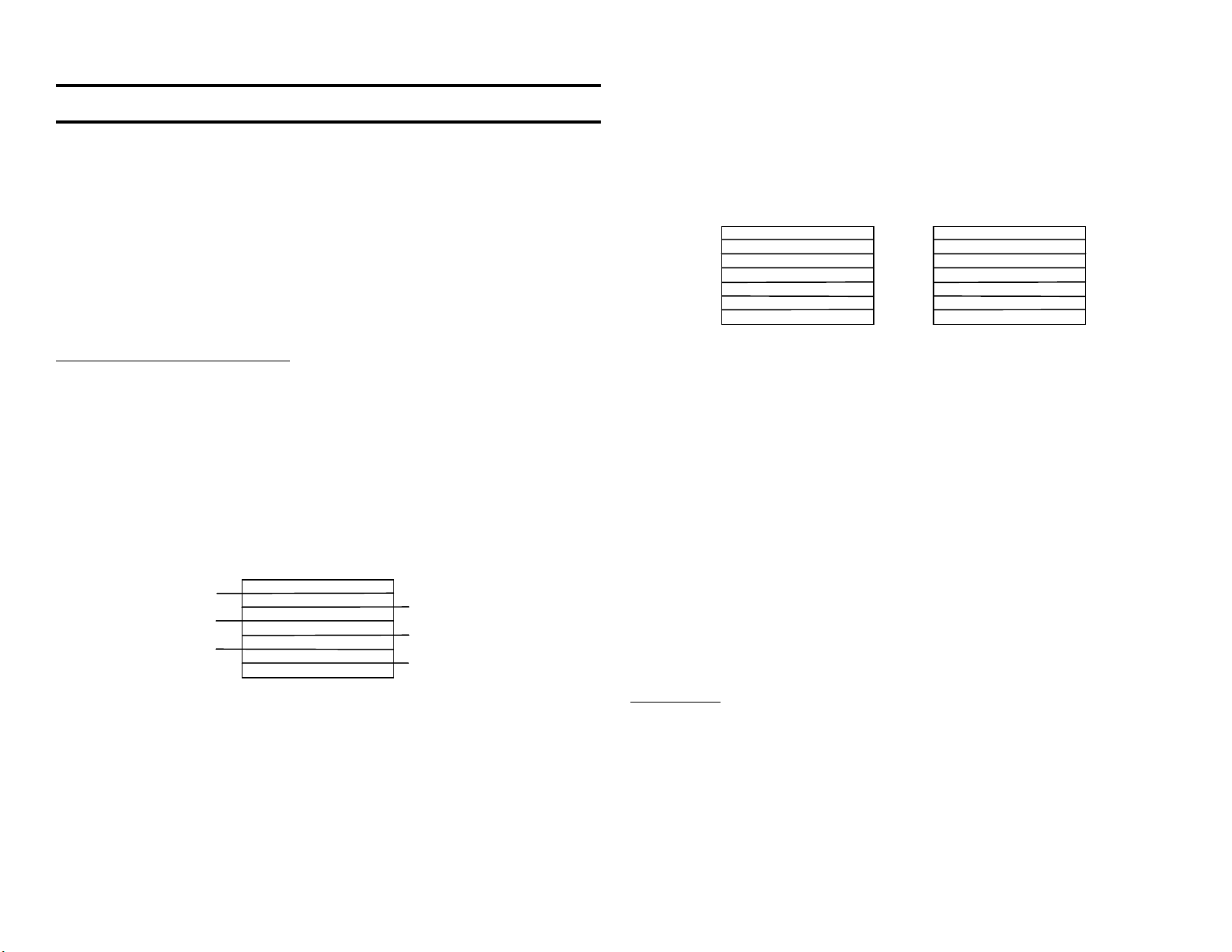
Composite Signal Input (B Board)
The NTSC format video from one of the two tuners or video inputs 1-4 is
selected by composite video switch IC3201. The user makes the selection from the remote to the Main uCom IC701 through the I2C bus into
IC3201 (not shown).
There are three outputs from IC3201:
IC3201 Outputs
Name Location Output Type Destination
Main CN3201/pin 1
Composite or Y (if S
video input TV)
Sub IC3201/pin
Separate Y / C Y/C Sub
56, 58
Monitor IC3201/pin Composite Rear panel output
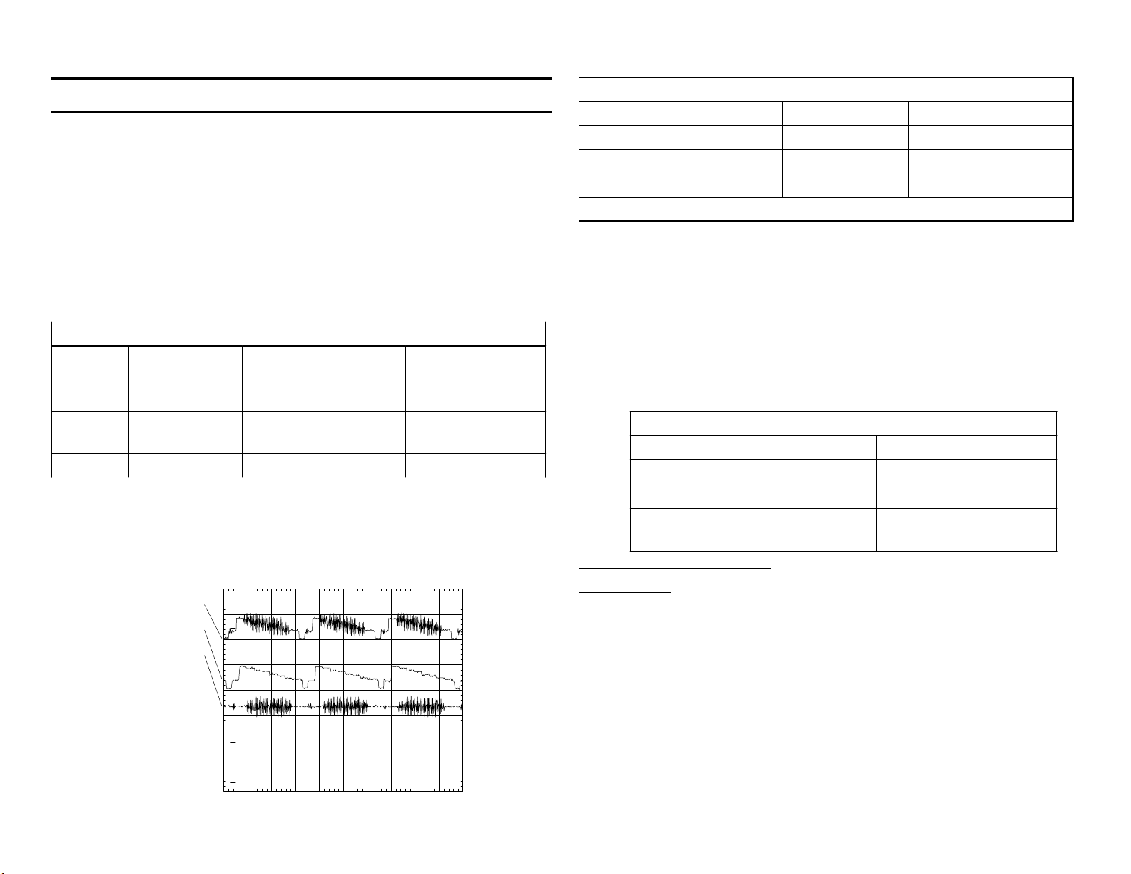
Y & C Separation (B Board)
The main composite signal enters the BC board that plugs into the larger
B board. The 3D Comb filter separates the luminance from the chroma,
pixel by pixel to output Y and C signals. The input and outputs of the
Comb filter are accessible and shown as 2Vp-p signals with a DC component in this scope shot:
ch1
ch2
ch3
1
3D Comb filter
IC3501
processor
3D Comb Filter - Color Bar input
Channel Name Location Comments
1 Input CN3201/pin 1 2Vp-p
2 Y Output CN3201/pin 3 2Vp-p
3 C Output CN3201/pin 5 1.7Vp-p
Time base = 20usec/div
Component Video Conversion (B Board)
The separate Y & C main signal is matrixed into component Y, Pb, and Pr
signals inside IC3048. This IC3048 can therefore act as a switch to choose
between the component video input from Video 5, Video 6 or the main
signal from the 3D Comb filter.
An additional RGB signal from the closed caption / V Chip IC3602 can be
matrixed into the signal path by IC3048 if these features are selected by
the user.
There are three outputs from IC3048:
IC3048 Outputs
Name Output Type Destination
Main Signal Component Main/Sub selector
H & V Sync 1Vp-p Sync selector IC3004
Comp Video 1Vp-p CCD/V Chip IC3602,
ID-1 IC3603
Comp Video / ID-1 Concept
ID-1 Concept
ID-1 is a relatively new concept. The ID-1 signal is hidden in the vertical
blanking area of the picture. This ID-1 signal identifies the aspect ratio of
the picture. IC3603 finds the signal and outputs data to the microprocessor. The micro can change the vertical or horizontal size to present the
picture properly. Recently, an ID-2 signal containing the aspect ratio and
copy guard information has been proposed.
2
CH1!2.00 V~
CH2 !2.00 V= S TOP
3
CH3!2.00 V= CHP MTB20.0us line ch1p
Main Signal Path
The main component video and sync signals are sent to switches IC3002
(video) and IC3004 (sync). They switch between the main and sub pictures. The outputs go to the Digital Reality Creation IC3303.
MAIN
TUNER
SUB
TUNER
A BD.
VIDEO 1 - 4
480i FORMAT
MONITOR OUT
VIDEO
5 - 6
480i/
480p/
1080i
U BD.
CN003/
CN3203
A10
A8
63
IC3003
SUB
COMB
A25 41
Y,Pb, Pr
6
IC3201
A/V
SW - 1
Y
C
CN3201/
CN3500
44
COMPOSITE/
Y
47
(S VIDEO)
SUB PIX
COMPOSITE
VIDEO
IC3110
VID 5,6
1
15
C
SUB OUT
Y/C TO:
YCT SUB
(IC3110)
BC BOARD
76
IC3501
3D COMB
FILTER
96
83 84
C
5 3
C
48
IC3048
YCT
MAIN
Y
Y
46
HTIM,VTIM
RGB
VIN
1
VIN
IC3603
ID - 1 DEC
DATA CLK
B BD.
CN3500/
CN3201
MAIN
Y,Pb,Pr
IC3602
CLOSE CAP
V CHIP
IC3001
COMP J - F
SUB
Y,Pb,Pr
(IC3110)
MAIN
Y,Pb,Pr
IC3002
YCT
SEL
MAIN
IC3004
DRC
SYN
SEL
HTIM/VTIM SYNC
TO IC3413
I2C/ BUS (TO MID
uCOM IC3090)
COMPONENT
VIDEO TO IC3414
DRC CD
SEL/
SYNC-SEL
MID-uCOM
IC3090
HD,
VD
SUB
TO
DRC - MF
IC3303
HD - S
VD - S
(IC3110)
VIDEO BLOCK 1/2
22
4ADTV02 1254
10/2/00
23
PM3394, FLUKE & PHILIPS
Digital Reality Creation
rd
This 3
generation device has three main purposes:
• Doubles the number of pixels on each scanning line after analyzing
the pixels in the immediate area.
• Creates double the number of scanning lines by prediction.
• Doubles the horizontal frequency to match the new image.
The input is analog component video and the output is an 8 bit parallel
port for each of the three component lines - Y, Pb and Pr. The digital
output goes to the MID circuit IC3408.
Multi Image Driver (MID) Circuit
The purpose of the MID circuit is to:
• Displays two images on the same screen (Main and Sub or Main and
High resolution).
• Add 60 blank lines to the picture.
• Change the input signal’s horizontal frequency from 31.5kHz to
33.75kHz.
• Instruct the related MID uCom IC3090 what the input horizontal fre-
quency is so it can control the sync path and aspect ratio.
Any input signal selected is present at the MID-XA signal processor IC3408,
so it knows what the input horizontal frequency is. Using this information,
the interconnected MID-uCom IC3090 can control the signal and sync
routing as well as send information to the Y/C CRT Drive IC201 for vertical reduction.
MID-uCom IC3090 Outputs
To summarize the MID functions, 60 lines are added to the picture by the
MID-XA main signal processor IC3408 when the horizontal frequency is
not 33.75kHz. MID-uCom IC3090 instructs oscillator IC201 to reduce the
vertical amplitude when the sync is 33.75kHz (High Definition signal).
Signal and Sync Switches
Using control signal from MID-uCom IC3090, switches IC3414 and IC3413
select final signal and sync for the Y/C CRT Drive IC201.
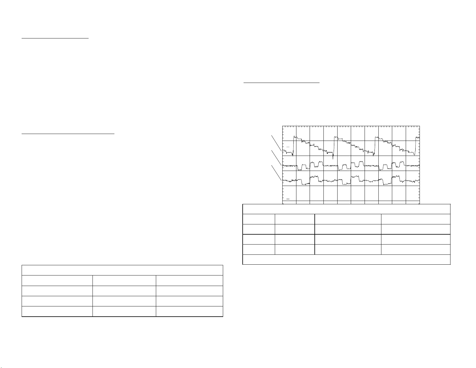
The component video that leaves the B board is shown in the waveform:
ch 1
ch 2
ch 3
1
2
Component Video leaving the B board - Color Bar input
Channel Name Location Comments
1 MID Y CN3203/pin B8 0.7Vp-p
2 MID Cb CN3203/pin B9 0.7Vp-p
3 MID Cr CN3203/pin B10 0.7Vp-p
Time base = 10usec/div
Name Destination Purpose
DO, CO (data, clock) MID-XA IC3408 Add 60 blank lines
IIC data bus Y/C, CRT Drive Vertical Reduction
Sync Sel Sync Sw IC3413 Sync for IC201
The following waveforms show the horizontal sync compared to the Y
signal. After the MID circuit, the frequency is 33.75lkHz.
MAIN
Y,Pb,Pr
FROM
IC3002
(YCT-
SEL)
HD,VD
SYNC
FROM
IC3004
(DRC-SYN-
SEL)
II C BUS
COMPONENT
VIDEO
FROM IC3001
(AV-SW1)
IC3303
DRC - MF
MID-uCOM
IC3090
CONT:
TO IC3414
(YUV SW)
SYNC
SEL
YO-7
CRO-7
CBO-7
H+V
DO,CO
DATA/
CLK
Y,Pb,Pr
HIGH DEFINITION
VIDEO 5 OR 6
B BD.
IC3408
MID - XA
IC3402 64M
SDRAM
PROG VERT
HTIM
HD HORIZ.
IC3048 (YCT
MAIN)
VTIM
INTERLACE
VERT
IC3048,(YCT MAIN)
YO-7
CRO7
CBO-7
CONT.
MID-uCOM
IC3090
MAIN H,
IC3410
D/A
Y,Pb,Cr
MID
IC3414
YUV SW.
IC3413
SYNC
SW.
CN3203/
Y
CB
CR
CN003
MID
H
MID
V
OSD,RGB
FROM MAIN uCOM
IC701
H DRIVE
IC201
Y/C
VIDEO
B8
B9
B10
B14
B15
CRT
DRIVE
SYNC
II C BUS
OFF MUTE
FROM MAIN
IC701/67,
Q708,Q730
V DRIVE
G
P
MUTE
POWER
uCOM
CN202/
CN9001
R
B
IK
10
C BD.
RGB
TO CRT
IC9001,
1
3
5
8
IC9002
IC9003
RGB
OUT
G2
MUTE
VIDEO BLOCK 2/2
24
A BD.
4BDTV02 1255
10/3/00
25
g
339 , U & S
Component Video leaving the B board - Color Bar input
ch1
ch2
ch3
1
2
CH1! 500mV~
3
CH2!2.00 V=
CH3!2.00 V= CHP MTB10.0us line ch1p
Channel Name Location Comments
1 Mid Y CN3203/pin B8 0.7Vp-p
2 Mid H CN3203/pin B14 3.8Vp-p
3 Mid V CN3203/pin B15 3.8Vp-p
Time base = 10usec/div
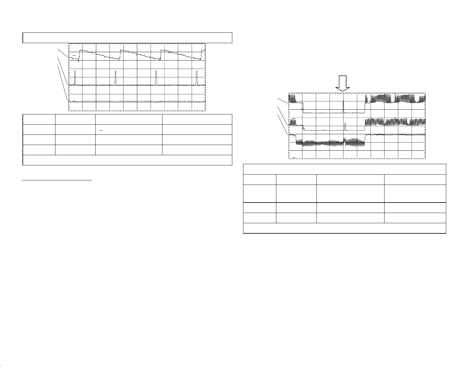
RGB Drive / AKB Circuit
The Y/C CRT Drive IC201 has several functions:
• Amplifies the RGB signal and applies it to the CRT cathodes
• Mixes the main signal with the RGB On-Screen Display (OSD)
• Automatic Cathode Balance (AKB) or IK (cathode current)
The AKB circuit monitors the CRT cathode currents and adjusts the RBG
drive levels to compensate for CRT aging. By adjusting RGB drive levels
to simulate the same cathode currents, white balance can be maintained.
To accomplish this task, at power ON three IK drive pulses (about 3Vp-p)
from IC201 are sent to each CRT cathode (video is muted). The cathode
currents from all three cathodes are returned to IC201 on the single IK
line. The three pulses are used to adjust the RGB drive pulses (and RGB
gain) to produce equal amplitude IK return pulse levels. When the AKB
loop closes, the AKB drive pulse is reduced (1.8Vp-p - ch 2). Finally, the
video signal is unmuted to display a picture.
(vertical blanking area of ch 1) is still at 3Vp-p (power On level). The
normal green signal (ch 2) shows the IK signal is reduced to 1.8Vp-p
because the IK loop is complete. The last waveform (ch 3) does not show
the missing red IK signal because of sampling errors in the digital scope
used.
ch1
ch2
ch3
T
1
2
CH1!2.00 V=
CH2!2.00 V=
CH3!1.00 V= CHP MTB 500us- 1.08dv ch1-
3
IK drive pulses
Vertical blankin
IK drive signal in the vertical interval - Color Bar input
Channel Name Location (C board) Comments
1 R Drive CN9001/pin 1
4Vp-p (open
circuited)
2 G Drive CN9001/pin 3 3Vp-p
3 B Drive CN9001/pin 8 1.4Vp-p
Time base = 0.5msec/div
Technical Note: If one or two cathodes falls below AKB adjustment range,
the video will NOT blank as in other AKB circuits. However, if a cathode
draws too much current, (Ik pulse gets large) the picture will blank, and
the standby light will blink five times and repeat.
In normal operation, if you increase the screen voltage, the IK return pulses
(ch 3) will increase in amplitude because more cathode current is drawn.
Because of the AKB closed loop, IC201’s output IK drive pulses (ch 2) will
decrease to lower the cathode current.
To see the full operation in the next scope shot, the red drive wire has
been opened at CN9001/pin 1. The CN9001/pin 1 connector is shorted to
ground to simulate a defect red cathode. Notice the red IK drive pulse
 Loading...