

SONY KV-32XBR400, KV-36XBR400, KV-38DRC1, KV-38DRC1C Service Manual Part3
SECTION 3
SET-UP ADJUSTMENTS
KV-32XBR400/36XBR400/38DRC1/38DRC1C
The following adjustments should be made when
a complete realignment is required or when a new
picture tube is installed.
These adjustments should be performed with rated
power supply voltage unless otherwise noted.
Set the controls as follows unless otherwise noted:
VIDEO MODE: ST ANDARD
PICTURE control: ............... 100%
BRIGHTNESS control: ....... 50%
3-1. BEAM LANDING
Before beginning adjustment procedure:
• Input a white pattern signal.
• Face the picture tube in East or West direction to reduce the
influence of geomagnetism.
NOTE: Do not use hand degausser because it magnetizes CRT.
1. Input white pattern from pattern generator. Set the
PICTURE control to maximum and BRIGHTNESS control
to standard.
2. Perform Focus, G2 and White Balance adjustments.
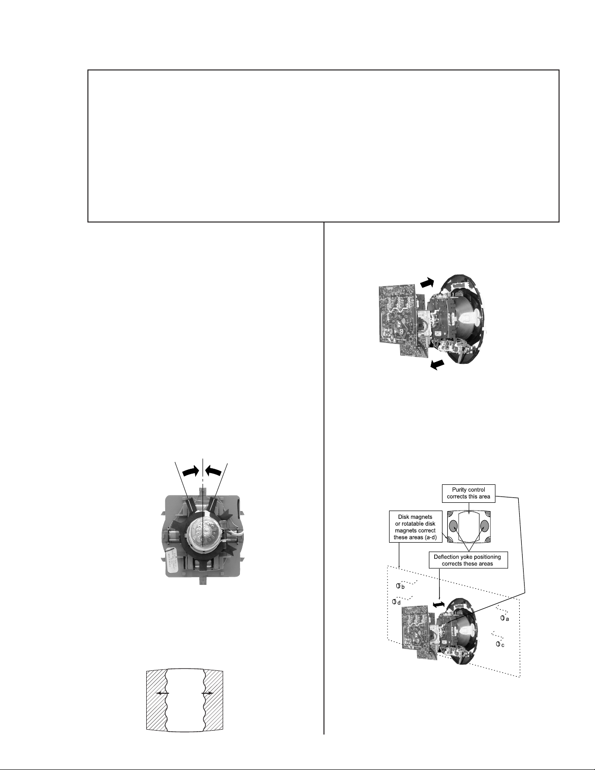
3. Loosen the deflection yoke mounting screw and set the
purity control to the center as shown below.
Purity Control
Perform the adjustments in order as follows:
1. Beam Landing
2. Convergence
3. Focus
4. Screen (G2)
5. White Balance
Note: T est equipment required:
• Color Bar Pattern Generator
• Degausser
• DC Power Supply
• Digital Multimeter
6. Move the deflection yoke forward and adjust so that the
entire screen becomes green.
7. Switch over the raster signal to red and blue and confirm
the condition.
8. When the position of the deflection yoke is determined,
tighten it with the deflection yoke mounting screw.
9. If landing at the corner is not right, adjust by using the disk
magnets.
4. Input a green pattern from the pattern generator.
5. Move the deflection yoke backwards and adjust the purity
control so that green is in the center and red and blue are
even on both sides.
Blue Red
Green
ﱢﱡ
cd
— 15 —
KV-32XBR400/36XBR400/38DRC1/38DRC1C
3-2. V-PIN and V-CEN ADJUSTMENT
Before beginning adjustment procedure:
• Input a cross hatch pattern signal.
• Face the picture tube in North/South direction and correct
rotation.
1. Set PICTURE control to 100% and BRIGHTNESS control
to 50%.
2. Adjust service mode CXA2150D-1 04 VCEN so that top
pin and bottom pin are symmetrical from top to bottom.
3. Adjust service mode CXA2150D-1 05 VPIN so top and
bottom pin are symmetrical from top to bottom.
4. Lines should be straight from left to right. Check landing for
side effect.
3-3. Con vergence Adjustment
Before starting convergence adjustments:
• Set CONTRAST AND BRIGHTNESS control to 50%.
• Input HD dot pattern.
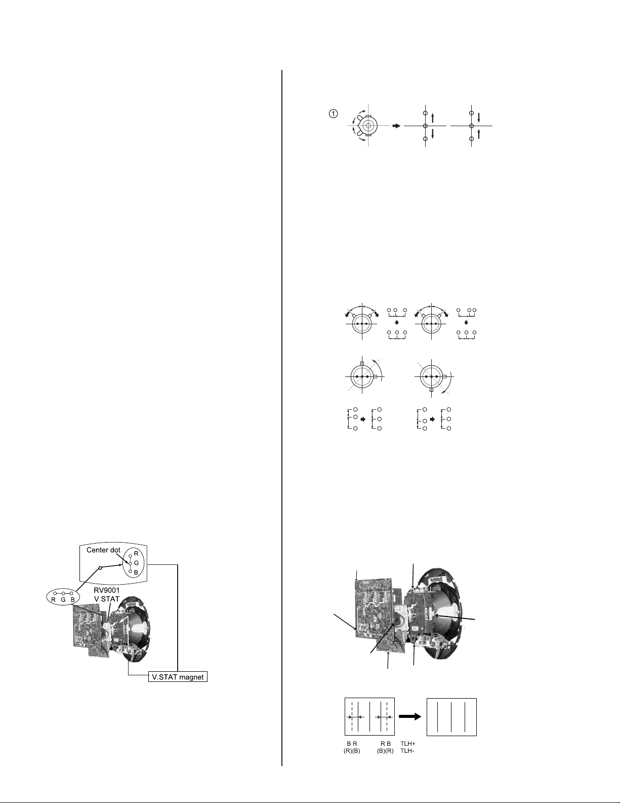
5. Tilt the V.STAT magnet and adjust static convergence to
open or close the V.STAT magnet.
B
G
R
B
G
R
Operation of BMC (Hexapole) Magnet
The respective dot positions resulting from moving each
magnet interact, so perform the following adjustment while
tracking.
Use the V.STAT tabs to adjust the red, green, and blue dots
so they line up at the center of the screen (move the dots in
a horizontal direction.)
HMC Correction HMC Correction
A<B
GB
R
AB
RGB
A=B
AB
VMC Correction
VMC Correction
A=B
A>B
RGB
GB
R
AB
AB
Vertical and Horizontal Static Convergence
1. Disconnect dynamic convergence before adjusting static
convergence (CN5510), except for minor touch-up.
2. Adjust H.ST AT convergence, RV 9001, to conver ge red,
green and blue dots in the center of the screen.
3. Adjust V.STAT magnet to converge red, green and blue
dots in the center of the screen.
4. If horizontal convergence is not correct, adjust V.STAT
manget and R V9001 on C Board while tracking.
C<D
C=D
R
C
G
D
R
G
B
B
C<D
C=D
R
C
G
D
R
G
B
B
TLH Plate Adjustment
• Input crosshatch pattern.
• Adjust PICTURE QUALITY to standard, PICTURE and
BRIGHTNESS to 50%, and OTHER to standard.
• Adjust unbalanced horizontal convergence of red and blue
dots by adjusting TLH plate on the deflection yoke.
RV9002
C Board
RV9001
V Board
TLV
TLH Plate
XCV
— 16 —
 Loading...