

SONY KV-32XBR200, KV-36XBR200 Service Manual
KV-32XBR200/KV-36XBR200
SERVICE MANUAL
MODEL COMMANDER DEST. CHASSIS NO.
KV-32XBR200
KV-32XBR200
KV-36XBR200
KV-36XBR200
RM-Y144 US SCC-S18A-A
RM-Y144 CND SCC-S19A-A
RM-Y144 US SCC-S18D-A
RM-Y144 CND SCC-S19D-A
AA-2H
CHASSIS
KV-36XBR200
RM-Y144
TRINITRON® COLOR TV
— 1 —
KV-32XBR200/KV-36XBR200
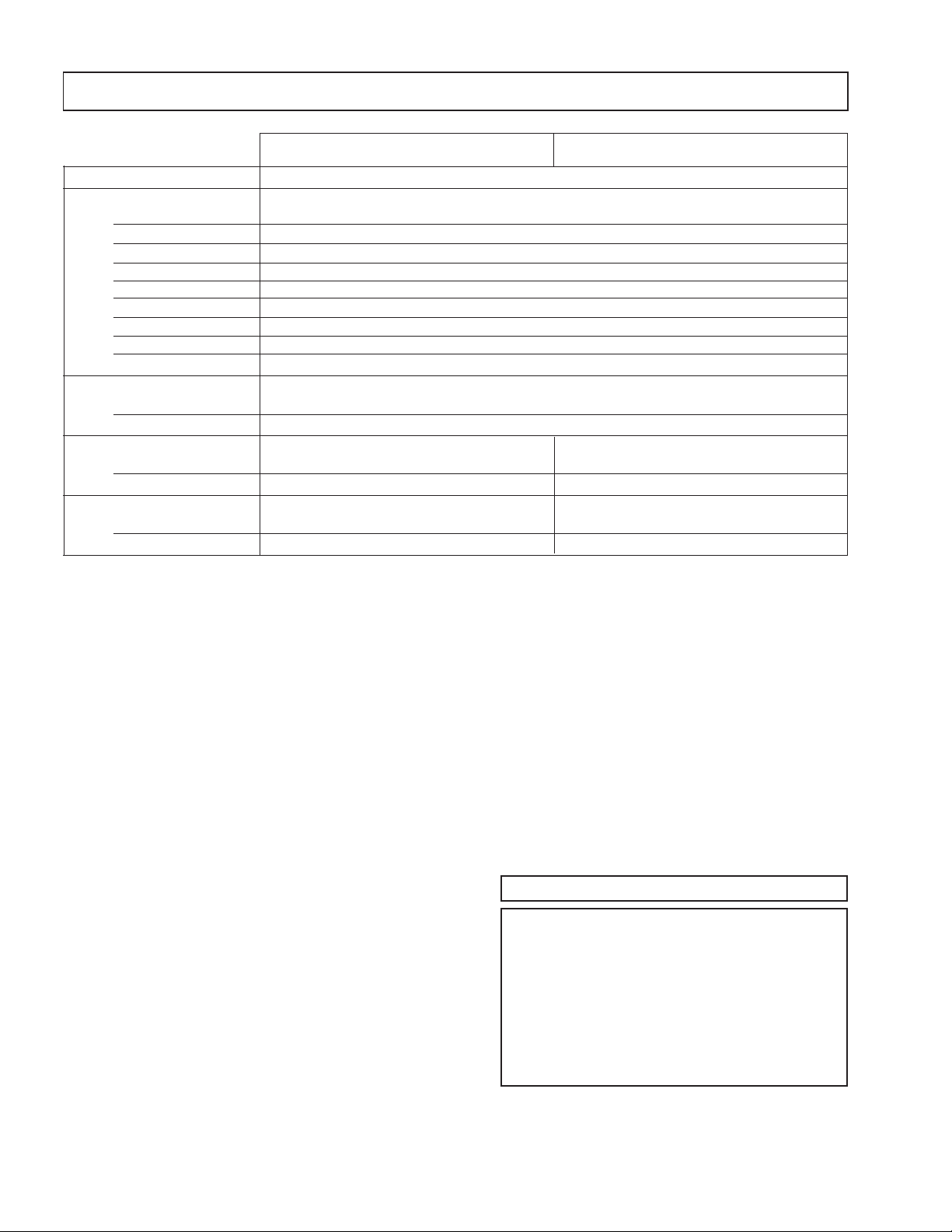
SPECIFICATIONS
KV-32XBR200 KV-36XBR200
Power requirements 120V, 60Hz
Number of inputs/outputs:
Power Consumption (W):
Dimensions (W/H/D):
Mass:
Television system
American TV standard, NTSC
Channel coverage
VHF:2-13 / UHF:14-69 / CATV:1-125
1)
Video
S Video
Audio
Audio Out
2)
3)
4)
Monitor Out 1
TV Out
1) 3)
S-link 3
B, PR
5)
Y, P
Speaker output (W) 15W x 2
In use (max.) 240W
In standby 2W
(mm) 889.4 x 685.6 x 600.7 mm 1010 x 761.2 x 630.9 mm
(in.) 35
7/16
x 27 x 23
21/32
in 35
(kg.) 79 kg 107 kg
(lbs.) 175 lbs 236 lbs
1)
1 Vp-p 75 ohms unbalanced, sync negative
2)
Y: 1 Vp-p 75 ohms unbalanced, sync negative
C: 0.286 Vp-p (Burst signal), 75 ohms
3)
500 mVrms (100% modulation), Impedance: 47 kilohms
4)
More than 408 mVrms at the maximum volume setting (variable)
More than 408 mVrms (fix); Impedance (Output): 2 kilohms
5)
Y: 1.0 Vp-p, 75 ohms, sync negative; PB: 0.7 Vp-p, 75 ohms; PR: Vp-p, 75 ohms
3
2
4
1
1
1
13/16
x 30 x 24
15/16
in
Visible screen size
32-inch picture measured diagonally (KV-32XBR200)
36-inch picture measured diagonally (KV-36XBR200)
Actual screen size
34-inch picture measured diagonally (KV-32XBR200)
38-inch picture measured diagonally (KV-36XBR200)
Antenna
75 ohm external antenna terminal for VHF/UHF
Picture tube
FD Trinitron
®
tube
Supplied accessories
Remote control RM-Y144
Battery size AA (R6) 2
Optional accessory
Connecting Cables
RK-74A, RK-G69HG,
VMC-10HG, VMC-720M,
VMC-810S/820S, YC-15V/30V ,
TV Stand SU-32FD1, SU-36FD1
U/V mixer EAC-66
Design and specifications are subject to change without notice.
( l ) SRS (SOUND RETRIEVAL SYSTEM)
The ( l ) SRS (SOUND RETRIEVAL SYSTEM) is manufactured by Sony Corporation under license from SRS Labs,
Inc. It is covered by U.S. Patent No. 4,748,669. Other U.S.
and foreign patents pending.
The word ‘SRS’ and the SRS symbol ( l ) areregistered
trademarks of SRS Labs, Inc.
BBE and BBE symbol are trademarks of BBE Sound, Inc.
and are licensed by BBE Sound, Inc. under U.S. Patent
No. 4,638,258 and 4,482,866.
— 2 —

TABLE OF CONTENTS
Section Title PageSection Title Page
KV-32XBR200/KV-36XBR200
1. GENERAL
Remote Control............................................................. 5
Connecting and Installing the TV.................................. 5
Cable Box Connections ............................................ 5
VCR Connections...................................................... 5
DBS Connections...................................................... 6
DVD Player Connections .......................................... 6
Additional Connections ............................................. 6
Using your New TV....................................................... 7
Watching the TV........................................................ 8
Watching two programs at one time - PIP................. 8
Using Your Menus ........................................................ 9
Learning menu selection ........................................... 9
Using the VIDEO menu............................................. 9
Using the AUDIO menu........................................... 10
Using the TIMER menu........................................... 10
Using the SET UP menu ......................................... 10
Operating Video Equipment ....................................... 12
VCR manufacturer code numbers........................... 12
MDP manufacturer code numbers .......................... 12
Operating a cable box DBS or DBS receiver.............. 12
Troubleshooting .......................................................... 12
2. DISASSEMBLY
2-1. Rear Cover and Speaker Removal..................... 13
2-2. Chassis Assembly Removal ............................. 13
2-3. Service Position ................................................ 13
2-4. Control Assy Removal ...................................... 13
2-5. Extension Cable Removal ................................ 14
2-6. Picture Tube Removal ...................................... 15
3. SET-UP ADJUSTMENTS
3-1. Beam Landing................................................... 16
3-2. Convergence .................................................... 17
3-3. Focus ................................................................ 18
3-4. Screen (G2) ...................................................... 18
3-5. White Balance Adjustment................................ 18
4. SAFETY RELATED ADJUSTMENTS ........................ 19
5. CIRCUIT ADJUSTMENTS ......................................... 20
6. DIAGRAMS
6-1. Block Diagram .................................................. 31
6-2. Circuit Boards Location..................................... 34
6-3.
Printed Wiring Boards and Schematic Diagrams .
39
• A Board........................................................... 39
• AX Board ........................................................ 45
• BX Board ........................................................ 47
• HF Board ........................................................ 50
• HX Board ........................................................ 50
• C Board .......................................................... 51
• G Board .......................................................... 53
• K Board........................................................... 55
• WA Board ....................................................... 57
• PX Board ........................................................ 59
• UX Board ........................................................ 63
6-4. Semiconductors ................................................ 68
7. EXPLODED VlEWS
7-1. Chassis ............................................................. 69
7-2. Picture Tube ..................................................... 70
8. ELECTRICAL PARTS LIST ....................................... 71
CAUTION!
SHORT CIRCUIT THE ANODE OF THE PICTURE TUBE AND THE
ANODE CAP TO THE METAL CHASSIS, CRT SHIELD, OR CARBON
PAINTED ON THE CRT, AFTER REMOVING THE ANODE.
WARNING!!
AN ISOLATION TRANSFORMER SHOULD BE USED DURING ANY
SERVICE TO AVOID POSSIBLE SHOCK HAZARD, BECAUSE OF LIVE
CHASSIS.
THE CHASSIS OF THIS RECEIVER IS DIRECTLY CONNECTED TO
THE AC POWER LINE.
SAFETY-RELATED COMPONENT WARNING!!
COMPONENTS IDENTIFIED BY SHADING AND MARK ¡ ON
THE SCHEMATIC DIAGRAMS, EXPLODED VIEWS AND IN THE
PARTS LIST ARE CRITICAL FOR SAFE OPERATION. REPLACE
THESE COMPONENTS WITH SONY PARTS WHOSE PART
NUMBERS APPEAR AS SHOWN IN THIS MANUAL OR IN
SUPPLEMENTS PUBLISHED BY SONY. CIRCUIT ADJUSTMENTS
THAT ARE CRITICAL FOR SAFE OPERATION ARE IDENTIFIED
IN THIS MANUAL. FOLLOW THESE PROCEDURES WHENEVER
CRITICAL COMPONENTS ARE REPLACED OR IMPROPER
OPERATION IS SUSPECTED.
ATTENTION
APRES AVOIR DECONNECTE LE CAP DE L'ANODE, COURT-CIRCUITER
L'ANODE DU TUBE CATHODIQUE ET CELUI DE L'ANODE DU CAP AU
CHASSIS METALLIQUE DE L'APPAREIL, OU AU COUCHE DE CARBONE
PEINTE SUR LE TUBE CATHODIQUE OU AU BLINDAGE DU TUBE
CATHODIQUE.
ATTENTION!!
AFIN D'EVITER TOUT RESQUE D'ELECTROCUTION PROVENANT D'UN
CHÁSSIS SOUS TENSION, UN TRANSFORMATEUR D'ISOLEMENT DOIT
ETRE UTILISÉ LORS DE TOUT DÉPANNAGE. LE CHÁSSIS DE CE
RÉCEPTEUR EST DIRECTEMENT RACCORDÉ À L'ALIMENTATION
SECTEUR.
ATTENTION AUX COMPOSANTS RELATIFS A LA SECURITE!!
LES COMPOSANTS IDENTIFIES P AR UNE TRAME ET P AR UNE MARQ UE
¡ SUR LES SCHEMAS DE PRINCIPE, LES VUES EXPLOSEES ET LES
LISTES DE PIECES SONT D'UNEIMPORTANCE CRITIQUE POUR LA
SECURITE DU FONCTIONNEMENT. NE LES REMPLA CER QUE P AR DES
COMPOSANTS SONY DONT LE NUMERO DE PIECE EST INDIQUE DANS
LE PRESENT MANUEL OU DANS DES SUPPLEMENTS PUBLIES PAR
SONY. LES REGLAGES DE CIRCUIT DONT L'IMPORTANCE EST CRITIQUE POUR LA SECURITE DU FONCTIONNEMENT SONT IDENTIFIES
DANS LE PRESENT MANUEL. SUIVRE CES PROCEDURES LORS DE
CHAQUE REMPLACEMENT DE COMPOSANTS CRITIQUES, OU
LORSQU'UN MAUVAIS FONTIONNEMENT SUSPECTE.
— 3 —
KV-32XBR200/KV-36XBR200
SAFETY CHECK-OUT
After correcting the original service problem, perform the
following safety checks before releasing the set to the
customer:
1. Check the area of your repair for unsoldered or poorlysoldered connections. Check the entire board surface
for solder splashes and bridges.
2. Check the interboard wiring to ensure that no wires
are “pinched” or contact high-wattage resistors.
3. Check that all control knobs, shields, covers, ground
straps, and mounting hardware have been replaced.
Be absolutely certain that you have replaced all the
insulators.
4. Look for unauthorized replacement parts, particularly
transistors, that were installed during a previous
repair. Point them out to the customer and
recommend their replacement.
5. Look for parts which, though functioning, show
obvious signs of deterioration. Point them out to
the customer and recommend their replacement.
6. Check the line cords for cracks and abrasion.
Recommend the replacement of any such line cord
to the customer.
7. Check the B+ and HV to see if they are specified
values. Make sure your instruments are accurate;
be suspicious of your HV meter if sets always have
low HV.
8. Check the antenna terminals, metal trim, “metallized"
knobs, screws, and all other exposed metal parts for
AC Leakage. Check leakage as described below.
LEAKAGE TEST
The AC leakage from any exposed metal part to earth ground
and from all exposed metal parts to any exposed metal part having
a return to chassis, must not exceed 0.5 mA (500 microampere).
Leakage current can be measured by any one of three methods.
1. A commercial leakage tester, such as the Simpson 229 or
RCA WT-540A. Follow the manufacturers' instructions to
use these instructions.
2. A battery-operated AC milliammeter. The Data Precision
245 digital multimeter is suitable for this job.
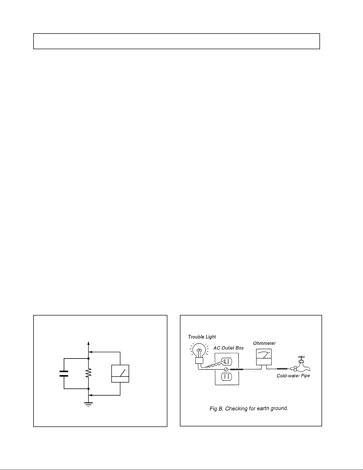
3. Measuring the voltage drop across a resistor by means of
a VOM or battery-operated AC voltmeter. The "limit"
indication is 0.75 V, so analog meters must have an accurate
low voltage scale. The Simpson's 250 and Sanwa
SH-63Trd are examples of passive VOMs that are suitable.
Nearly all battery operated digital multimeters that have a
2V AC range are suitable. (See Fig. A)
HOW TO FIND A GOOD EARTH GROUND
A cold-water pipe is guaranteed earth ground; the cover-plate
retaining screw on most AC outlet boxes is also at earth gr ound.
If the retaining screw is to be used as your earth-ground, verify
that it is at ground by measuring the resistance between it and a
cold-water pipe with an ohmmeter . The r eading should be zer o
ohms. If a cold-water pipe is not accessible, connect a 60-l00 watts
trouble light (not a neon lamp) between the hot side of the receptacle and the retaining screw. Try both slots, if necessary, to
locate the hot side of the line, the lamp should light at normal
brilliance if the screw is at ground potential. (See Fig. B)
To Exposed Metal
Parts on Set
1.5 k
0.15 µF
Fig. A. Using an AC voltmeter to check AC leakage.
Ω
Earth Ground
AC
Voltmeter
(0.75 V)
— 4 —
— 5 —
TV/VIDEO
(page 16)
ANT (page 16)
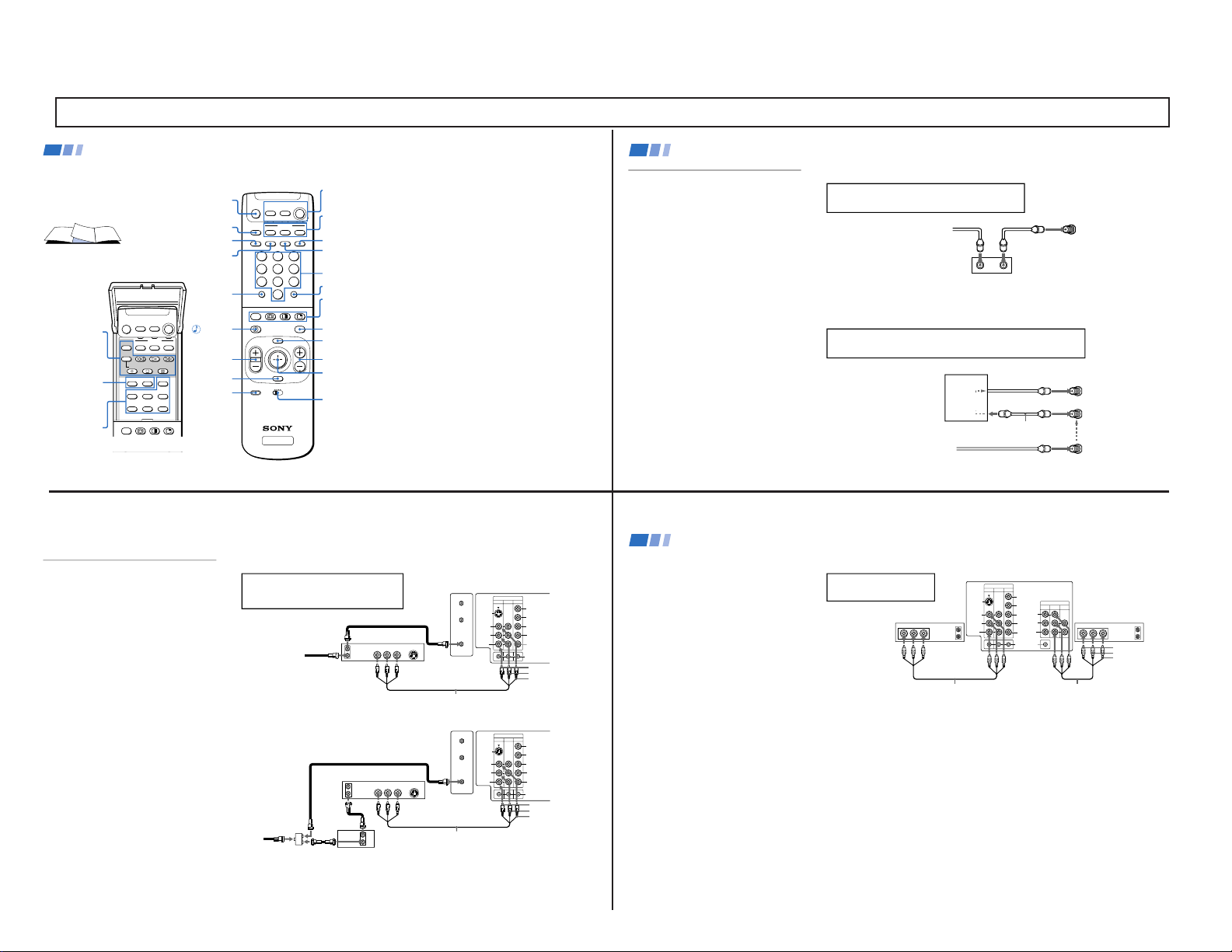
In the instructions that follow, we will
refer to the buttons on your remote control.
Keep this flap unfolded and use this page
for reference.
Getting to know the buttons on the
remote control
Names of the buttons on the remote
control are presented in different colors to
represent the available functions.
Button color
Black ................ Press to select the component
you want to control; e.g. VTR
(VCR)/MDP/DVD Player, DBS
(Direct Broadcast Satellite)/
CABLE, or TV
Green ............... Buttons relevant to power
operations, like turning the TV,
DBS (Direct Broadcast Satellite)/
CABLE, or VTR (VCR)/MDP/
DVD Player on or off
Label color
White ............... TV/VTR (VCR)/MDP/DVD
Player/DBS (Direct Broadcast
Satellite)/CABLE operation
buttons
Yellow.............. PIP, P&P, and CHANNEL
INDEX operation buttons
Blue .................. DBS (Direct Broadcast Satellite)
operation buttons
Green ............... S-Link operation buttons
Pink .................. DVD Player operation buttons
For a detailed explanation of most buttons, see
"Watching the TV" on page 15.
Remote Control
MUTING
(page 15)
POWER
(page 15)
FUNCTION
(page 15)
ENTER
0 – 9 Buttons
MTS/GUIDE
PIP/P&P/
CHANNEL INDEX
(pages 17-20)
VTR1/2/3/DVD/
MDP (page 31)
Joystick
(page 13)
CH +/–
MENU
RESET
VOL +/–
TV/DBS
JUMP
(page 15)
DISPLAY (page 16)
SLEEP (page 15)
SYSTEM OFF (page 16)
MTS
TV
MUTING
VTR/DVD DBS/CABLE
POWER
VTR/DVD DBS/CABLE
FUNCTION
TV
TITLE DVD MENU FREEZE
AUDIO SWAP CH
+
POSITION TV/VIDEO CH
-
TV/VTR
REC
GUIDE
TV/DBS
OFF
TV
213
546
879
0
TV
MTS
MUTING
VTR/DVD DBS/CABLE
POWER
VTR/DVD DBS/CABLE
FUNCTION
TVOFF
SYSTEM
SLEEP DISPLAY TV/VIDEO ANT
MENU
GUIDE
VOL
TV/DBS
RESET
CH
VTR 1 2 3 DVD/MDP
CODE SET
JUMP ENTER
OFF
RM -Y144
PIP/P&P
(pages 17, 18)
DVD
Operation
Buttons
(page 32)
VCR/DVD/MDP
Operation
Buttons
(page 32)
CODE SET
(pages 31, 33)
If you are connecting a cable box through the AUX input and would like
to switch between the AUX and normal (CATV) input you should consider
using the CHANNEL FIX feature. (see “CHANNEL SET UP” on page 26)
If you will be controlling all channel selection through
your cable box, you should consider using the CHANNEL
FIX feature. (see “CHANNEL SET UP” on page 26)
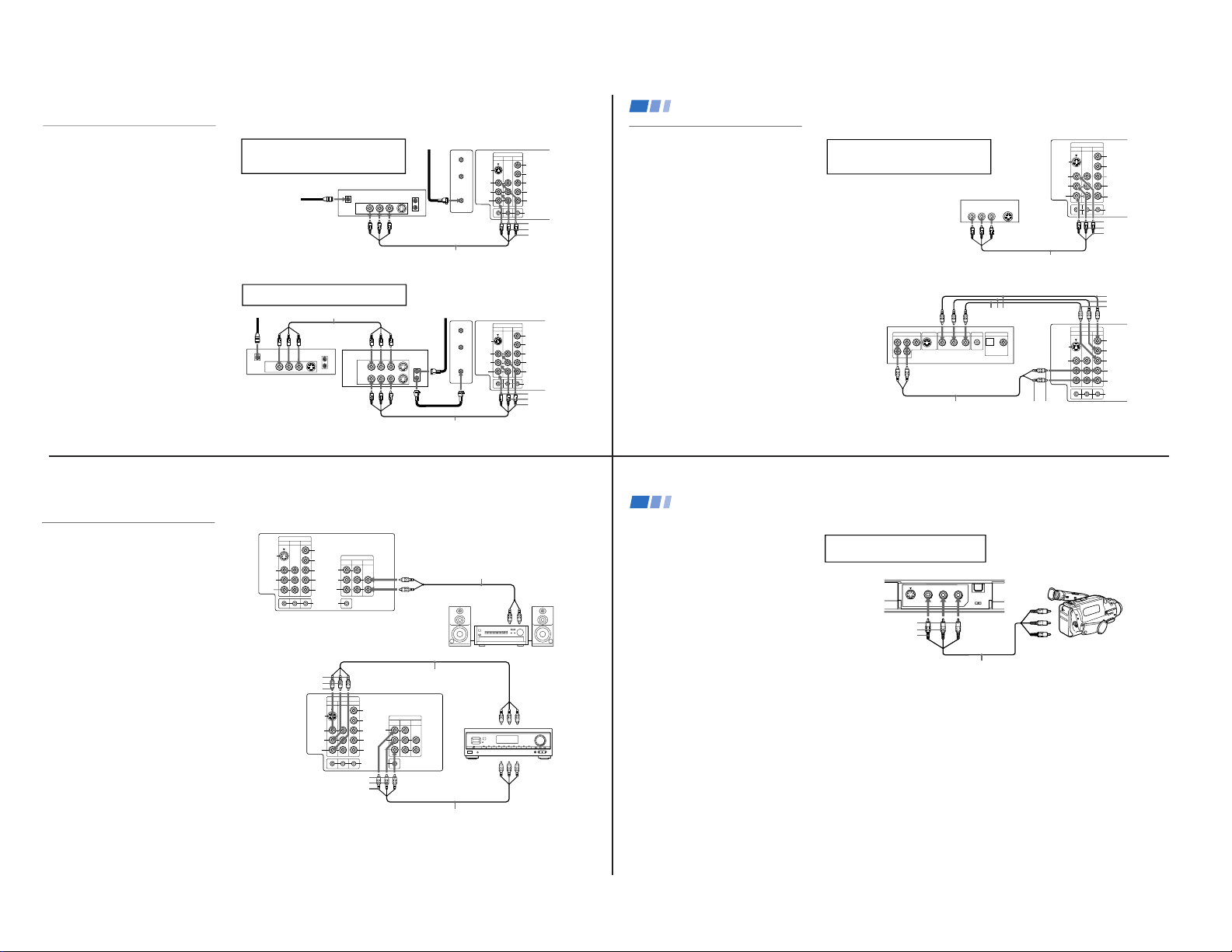
Cable Box Connections
Some pay cable TV systems use scrambled or
encoded signals that require a cable box to
view all channels.
Cable box
1 Connect the coaxial connector from your
cable to the IN on your cable box.
2 Using a coaxial cable, connect OUT on
your cable box to VHF/UHF on your TV.
Cable box and cable
For this set up, you can switch between
scrambled channels (through your cable box),
and normal (CATV) channels by pressing
ANT on your remote control.
Notes
• Your Sony remote control can be
programmed to operate your cable box.
(see “Operating a Cable Box or DBS
Receiver” on page 33)
• When using PIP, you cannot view the
AUX input in the window picture.
Tip z
Pressing ANT switches between these inputs.
Cable box
Cable
OUT
IN
(Rear of TV)
VHF/UHF
TO CONVERTER
Cable box
VHF/UHF
(Rear of TV)
AUX
75-ohm coaxial
cable (not supplied)
CATV cable
(unscrambled channels)
(signal)
scrambled
channels
Connecting and Installing the TV (continued)
4
VIDEO IN
134
L
R
(
MONO
)
VIDEO
S VIDEO
OUT
AUDIO
L
R
Y
P
B
P
R
AUDIO
S-LINK
CONTROL S
AUX
TO
CONVERTER
VHF/UHF
AUDIO R AUDIO L VIDEO
S VIDEO
LINE
OUT
OUT
IN
Disconnect all power sources before making any connections.
VCR Connections
Connecting an antenna/cable TV
system with a VCR
1 Attach the coaxial connector from your
cable or antenna to IN on your VCR.
2 Using A/V connectors, connect AUDIO
and VIDEO OUT on your VCR to AUDIO
and VIDEO IN on your TV*.
3 Using a coaxial connector, connect OUT on
your VCR to VHF/UHF on your TV.
* If you are connecting a monaural VCR, connect only the
single white audio output to the left input on your TV.
Connecting a VCR and TV with a
cable box
1 Connect the single (input) jack of the
splitter to your incoming cable connection,
and connect the other two (output) jacks
(using coaxial cable) to IN on your cable
box and VHF/UHF on your TV.
2 Using a coaxial connector, connect OUT on
your cable box to IN on your VCR.
3
Using A/V connectors, connect AUDIO and
VIDEO OUT on your VCR to AUDIO and
VIDEO IN on your TV.
Coaxial cable
(Rear of TV)
VMC-810S/820S (not supplied)
Cable
VCR
3
1
2
AUDIO-R (red)
AUDIO-L (white)
VIDEO (yellow)
For optimum picture quality, use S VIDEO
instead of the yellow A/V cable. S VIDEO does
not provide sound, your audio connectors
must still be connected.
VIDEO IN
134
L
R
(
MONO
)
VIDEO
S VIDEO
OUT
AUDIO
L
R
Y
P
B
P
R
AUDIO
S-LINK
CONTROL S
AUX
TO
CONVERTER
VHF/UHF
AUDIO R AUDIO L VIDEO
S VIDEO
LINE
OUT
OUT
IN
OUT
IN
(Rear of TV)
VMC-810S/820S (not supplied)
Cable box
Splitter
(not supplied)
3
AUDIO-R (red)
AUDIO-L (white)
VIDEO (yellow)
VCR
Cable
Coaxial cable
2
1
5
OUT
MONITOR
AUDIO
(
VAR/FIX
)
TV
VIDEO IN
134
IN
L
R
(
MONO
)
VIDEO VIDEO
S VIDEO
OUT
AUDIO
L
R
(
MONO
)
AUDIO
L
R
Y
P
B
P
R
AUDIO
S-LINK
CONTROL S
LINE
OUT
OUT
IN
LINE
IN
OUT
IN
AUDIO R AUDIO L VIDEO AUDIO R AUDIO L VIDEO
Disconnect all power sources before making any connections.
Connecting two VCRs
MONITOR OUT gives you the ability to use a
second VCR to record a program being played
by the primary VCR or to perform tape
editing and dubbing.
1 Connect the VCR intended for playback
using the connection instructions on page
4 of this manual.
2 Using A/V connectors, connect AUDIO
and VIDEO IN on your VCR intended for
recording to MONITOR AUDIO and
VIDEO OUT on your TV.
VCR (for playback)
VCR (for recording)
VMC-810S/820S (not supplied) VMC-810S/820S (not supplied)
(Rear of TV)
1
2
Do not change the input
signal while editing through
MONITOR OUT.
Connecting and Installing the TV (continued)
AUDIO-R (red)
AUDIO-L (white)
VIDEO (yellow)
6
SECTION 1 GENERAL
The instructions mentioned here are partial abstracts from the Operating Instruction Manual. The page numbers showm reflect those of the Operating Instruction Manual.
KV-32XBR200/KV-36XBR200
— 6 —
VIDEO IN
134
L
R
(
MONO
)
VIDEO
S VIDEO
OUT
AUDIO
L
R
Y
P
B
P
R
AUDIO
S-LINK
CONTROL S
AUX
TO
CONVERTER
VHF/UHF
VHF/UHF
S VIDEO
OUT
IN
LINE OUT
SATELLITE IN
AUDIO R AUDIO L VIDEO
VIDEO IN
134
L
R
(
MONO
)
VIDEO
S VIDEO
OUT
AUDIO
L
R
Y
P
B
PR
AUDIO
S-LINK
CONTROL S
AUX
TO
CONVERTER
VHF/UHF
AUDIO R AUDIO L VIDEO
AUDIO R AUDIO L VIDEO
SATELLITE IN
VHF/UHF
S VIDEO
OUT
IN
LINE OUT
LINE IN
VHF/UHF
S VIDEO
OUT
IN
LINE OUT
Disconnect all power sources before making any connections.
1
2
3
VMC-810S/820S (not supplied)
VMC-810S/820S (not supplied)
4
5
(Rear of TV)
DBS receiver
(Rear of TV)
Satellite
antenna
cable
VMC-810S/820S (not supplied)
1
3
2
DBS receiver
VCR
AUDIO-R (red)
AUDIO-L (white)
VIDEO (yellow)
DBS Connections
Connecting a DBS (Direct Broadcast
Satellite) receiver
1 Connect the cable from your satellite
antenna to your DBS receiver.
2 Attach the coaxial connector from your
cable or antenna to VHF/UHF on your TV.
3 Using A/V connectors, connect AUDIO
and VIDEO OUT on your DBS receiver to
AUDIO and VIDEO IN on your TV.
Connecting a DBS (Direct Broadcast
Satellite) receiver and a VCR
1 Connect the cable from your satellite
antenna to your DBS receiver.
2
Attach the coaxial connector from your cable
or antenna to VHF/UHF IN on your VCR.
3 Using a coaxial connector, connect VHF/
UHF OUT on your VCR to VHF/UHF on
your TV.
4 Using A/V connectors, connect AUDIO
and VIDEO OUT on your DBS receiver to
AUDIO and VIDEO IN on your VCR.
5 Using A/V connectors, connect AUDIO
and VIDEO OUT on your VCR to AUDIO
and VIDEO IN on your TV.
AUDIO-R (red)
AUDIO-L (white)
VIDEO (yellow)
Pressing TV/VIDEO on the remote control will
allow you to view from the DBS or VCR.
For optimum picture quality, use S VIDEO
instead of the yellow A/V cable. S VIDEO does
not provide sound, your audio connectors
must still be connected.
7
DVD Connections
Connecting a DVD Player
Using A/V connectors, connect VIDEO IN on
your TV to LINE OUT on your DVD Player.
Connecting a DVD Player with
component video output
connectors
This connection option offers the highest
quality DVD picture.
1 Using AUDIO connectors, connect AUDIO
R and L of the LINE OUT on your DVD
Player to AUDIO R and L on the VIDEO IN
4 panel at the rear of your TV.
2 Using three VIDEO connectors, connect Y,
P
B, and PR on the COMPONENT VIDEO
OUT on your DVD Player to Y, P
B, and P
R
on the VIDEO IN 4 panel at the rear of
your TV.
Note
• Some DVD Player terminals may be
labeled Y, C
B, and CR, or Y, B-Y, and R-Y.
If so, connect them by matching the colors.
Disconnect all power sources before making any connections.
VIDEO IN
134
L
R
(
MONO
)
VIDEO
S VIDEO
OUT
AUDIO
L
R
Y
P
B
P
R
AUDIO
S-LINK
CONTROL S
LINE OUT
S VIDEO OUT
S-LINK
DIGITAL OUT
R–AUDIO 1–L VIDEO
OPTICAL COAXIAL
R-YY B-Y
COMPONENT VIDEO OUT
RK-74A (not supplied)
DVD
(Rear of TV)
VMC-10HG (not supplied)
1
2
Connecting and Installing the TV (continued)
AUDIO-L
(white)
134
L
R
(
MONO
)
VIDEO
S VIDEO
OUT
AUDIO
L
R
Y
P
B
P
R
AUDIO
S-LINK
CONTROL S
VIDEO IN
AUDIO R AUDIO L VIDEO
S VIDEO
LINE OUT
VMC-810S/820S (not supplied)
1
(Rear of DVD player)
AUDIO-R (red)
AUDIO-L (white)
VIDEO (yellow)
(Rear of TV)
For better picture quality, use S VIDEO instead
of the yellow A/V cable. S VIDEO does not
provide sound, your audio connectors must
still be connected.
AUDIO-R
(red)
Y
P
B
PR
8
OUT
MONITOR
AUDIO
(
VAR/FIX
)
TV
VIDEO IN
134
IN
L
R
(
MONO
)
VIDEO VIDEO
S VIDEO
OUT
AUDIO
L
R
(
MONO
)
AUDIO
L
R
Y
PB
PR
AUDIO
S-LINK
CONTROL S
VIDEO IN
134
OUT
MONITOR
AUDIO
(
VAR/FIX
)
IN
TV
L
R
(
MONO
)
VIDEO VIDEO
S VIDEO
OUT
AUDIO
L
R
(
MONO
)
AUDIO
L
R
Y
PB
PR
AUDIO
S-LINK
CONTROL S
HRD
Line
input
AUDIO-R (red)
AUDIO-L (white)
RK-74A
(not supplied)
(Rear of TV)
1
2
Additional Connections
Connecting an audio system
For an enhanced sound, connect your audio
system to your TV.
1 Using AUDIO connectors, connect AUDIO
OUT on your TV to one of the unused Line
inputs (e.g. Tape-2, AUX1, etc.) on your
stereo.
2 Set your stereo to the chosen Line input
and use the AUDIO menu to set your
audio output. (see “SPEAKER” and
"AUDIO OUT" on page 24)
Connecting an A/V receiver
For easier control of all audio and video
equipment, connect your A/V receiver.
1 Using A/V connectors, connect VIDEO 1
IN on your TV to Monitor AUDIO and
VIDEO OUT on your A/V receiver.
2 Using A/V connectors, connect TV OUT
on your TV to TV AUDIO and VIDEO IN
on your A/V receiver.
Tip z
You may want to use CHANNEL FIX to fix your TV's
input to the A/V receiver (VIDEO 1). (see “CHANNEL
SET UP” on page 26)
Disconnect all power sources before making any connections.
VMC-10HG/30HG (not supplied)
A/V outputs
1
2
VMC-810S/820S (not supplied)
A/V inputs
A/V receiver
(Rear of TV)
AUDIO-R (red)
AUDIO-L (white)
VIDEO (yellow)
AUDIO-R (red)
AUDIO-L (white)
VIDEO (yellow)
9
Connecting and Installing the TV (continued)
Connecting a camcorder
This connection is convenient for viewing a
picture directly from your camcorder.
Using A/V connectors, connect AUDIO and
VIDEO OUT on your camcorder to AUDIO
and VIDEO IN on your TV.
Connection can also be made directly to your
A/V input located on the rear of your TV.
Note
•
If you are connecting a monaural camcorder,
connect only the single white audio output
to the left input on your TV.
If you have an S VIDEO equipped camcorder,
you can use an S Video cable for optimum
picture quality.
Disconnect all power sources before making any connections.
VIDEO 2 INPUT
VIDEO L
(MONO)
-AUDIO-R
S VIDEO
A/V output
VMC-810S/820S
(not supplied)
AUDIO-R (red)
AUDIO-L (white)
VIDEO (yellow)
10
KV-32XBR200/KV-36XBR200

— 7 —
Disconnect all power sources before making any connections.
Using Special Sony Features
Using the CONTROL S feature
CONTROL S allows you to control your TV
and other Sony equipment with one remote
control.
To control your other Sony equipment with
your TV's remote control, connect the
CONTROL S IN jack of the equipment to the
CONTROL S OUT jack on the TV with the
CONTROL S cable.
To control other Sony equipment with your
TV's remote control, see “S-Link Connections”
on page 12.
(Rear of TV)
VIDEO IN
134
OUT
MONITOR
AUDIO
(
VAR/FIX
)
IN
TV
L
R
(
MONO
)
VIDEO VIDEO
S VIDEO
OUT
AUDIO
L
R
(
MONO
)
AUDIO
L
R
Y
P
B
P
R
AUDIO
S-LINK
CONTROL S
IN
OUT
CONTROL S
11
OUT
IN
S VIDEO
LINE
OUT
AUDIO R AUDIO L VIDEO
VIDEO IN
134
OUT
MONITOR
AUDIO
(
VAR/FIX
)
IN
TV
L
R
(
MONO
)
VIDEO VIDEO
S VIDEO
OUT
AUDIO
L
R
(
MONO
)
AUDIO
L
R
Y
P
B
PR
AUDIO
S-LINK
CONTROL S
S-LINK
Disconnect all power sources before making any connections.
2
1
Connecting S-Link to your VCR
S-Link will automatically power on the TV and
switch to the correct video input when a tape is
inserted in the VCR or when you begin to play
a tape.
1 Using A/V connectors, connect AUDIO and
VIDEO OUT on your VCR to AUDIO and
VIDEO IN on your TV.
2 Using an S-LINK connector (mono mini
plug), connect S-LINK/CONTROL S-IN on
your VCR to S-LINK on your TV.
Connecting S-Link to your DBS
S-Link will automatically power on the TV and
switch to the correct video input when you
power on the DBS.
1 Using A/V connectors, connect AUDIO and
VIDEO OUT on your DBS to AUDIO and
VIDEO IN on your TV.
2 Using an S-LINK connector (mono mini
plug), connect S-LINK/CONTROL S-IN on
your DBS to S-LINK on your TV.
Note
•
If you have labeled one of your video inputs
as SKIP (see “VIDEO LABEL” on page 27)
and then connect video equipment to this
input using S-Link, the S-Link feature will
override the SKIP function.
RK-G69HG (not supplied)
(Rear of TV)
VCR
VMC-810S/820S (not supplied)
VHF/UHF
S VIDEO
OUT
IN
LINE
OUT
SATELLITE IN
AUDIO R AUDIO L VIDEO
VIDEO IN
134
OUT
MONITOR
AUDIO
(
VAR/FIX
)
IN
TV
L
R
(
MONO
)
VIDEO VIDEO
S VIDEO
OUT
AUDIO
L
R
(
MONO
)
AUDIO
L
R
Y
P
B
PR
AUDIO
S-LINK
CONTROL S
S-LINK
2
RK-G69HG (not supplied)
VMC-810S/820S (not supplied)
AUDIO-R (red)
AUDIO-L (white)
VIDEO (yellow)
1
(Rear of TV)
DBS
Connecting and Installing the TV (continued)
AUDIO-R (red)
AUDIO-L (white)
VIDEO (yellow)
The S-Link connector must be in the same
VIDEO-IN jacks as the A/V cables on your TV.
12
13
Inserting Batteries
Insert two size AA (R6) batteries (supplied) by
matching the + and – on the batteries to the
diagram inside the battery compartment.
Notes
• Remove the batteries to avoid damage
from possible battery leakage whenever
you anticipate that the remote control will
not be used for an extended period.
• Handle the remote control with care.
Avoid dropping it, getting it wet, or
placing it in direct sunlight, near a heater,
or where the humidity is high.
• Your remote control can be programmed to
operate most video equipment.
(see “Operating Video Equipment” on
page 31)
Using the Remote Control
Joystick
MTS
MENU
GUIDE
VOL
TV/DBS
RESET
CH
CODE SET
OFF
RM -Y144
VTR 1 2 3 DVD/MDP
The supplied remote control has a joystick
which allows for movement of the on-screen
selector. Pressing up, down, left, or right on
the joystick will cause the selector to move in
the corresponding direction. Pressing down
on the center of the joystick (
) will select
the item.
Adjustment Bars
When menu items present an adjustment bar
( or
), press up, down, left, or
right on the joystick to adjust the setting.
On Screen Help/Instructions
Several menu windows will provide prompts
and instructions to assist you in navigating
through the different functions.
When the instructions are presented, use them to
supplement the instructions in this manual.
Select
Basic Set Up
Using the buttons on the top of the TV:
SET UP TV/VIDEO
+
VOLUME
–+
CHANNEL
–
POWER
1 Press POWER to turn on the TV.
The Easy Setup Guide screen appears.
POWER
Press [SET UP] to exit.
First please connect
cable/antenna
DEMO:
AUTO SET UP:
ESPAÑOL:
ENGLISH:
FRANÇAIS:
[ TV / VIDEO ]
[ VOL – ]
[ CH – ]
[ CH + ]
[ VOL + ]
2 Press CHANNEL + to select ENGLISH,
CHANNEL – to select ESPAÑOL or
VOLUME + to select FRANÇAIS.
The screen will change to reflect your
choice.
+
VOLUME
+
CHANNEL
–
Oprima [SET UP]
para salir.
Primero conecte el
cable/antena
DEMO:
AUTO AJUSTES:
ESPAÑOL:
ENGLISH:
FRANÇAIS:
[ TV / VIDEO ]
[ VOL – ]
[ CH – ]
[ CH + ]
[ VOL + ]
For a DEMO of functions and menus,
press TV/VIDEO.
Setting Up the TV
Automatically
The Easy Setup Guide feature allows you to
set the on-screen language and set all
receivable channels in one step.
The AUTO PROGRAM function of the Easy
Setup Guide feature does not apply for
installations that use a cable box for all channel
selection.
You can also set up the TV manually. (see “Using
the SET UP menu” on page 26)
Tips z
• Perform this function during the day, with the
antenna and/or cable properly connected, to ensure
that all available channels will be broadcasting and
receivable.
• After using Easy Setup Guide you will still have the
option of adjusting any of the system settings, like
erasing channels, through the SET UP menu. (see
“CHANNEL SET UP” on page 26)
Using your New TV
3 Press VOLUME – to continue.
+
VOLUME
–
AUTO PROGRAM
AUTO PROGRAM appears and the TV starts
scanning and presetting channels
automatically. When all the receivable channels
are stored, the lowest numbered channel is
displayed. If the TV receives cable TV channels,
CABLE is set to ON automatically.
To perform AUTO SET UP again
Press the SET UP button on the TV and follow
steps 2–3.
Notes
• Before you perform Easy Setup Guide again,
make sure that the input from ANT (not
AUX) is selected by pressing ANT until
“AUX” does not appear next to the channel
number.
• When you perform AUTO PROGRAM, your
CHANNEL FIX, TIMER, and CHANNEL
BLOCK settings will be erased.
• To reset your TV to factory settings, turn the
TV on. Then, while pressing the RESET
button on your remote control, press the
POWER key on your TV. The TV will turn
itself off, then back on.
14
KV-32XBR200/KV-36XBR200
— 8 —
TV
VTR/DVD DBS/CABLE
POWER
VTR/DVD DBS/CABLE
FUNCTION
TV
0 9
-
CH
VOL
JUMP
MUTING
FREEZE
SLEEP
REFER TO THE ILLUSTRATION OF THE
REMOTE CONTROL ON THE INSIDE
FRONT COVER OF THIS MANUAL AS
YOU REVIEW THIS CHART
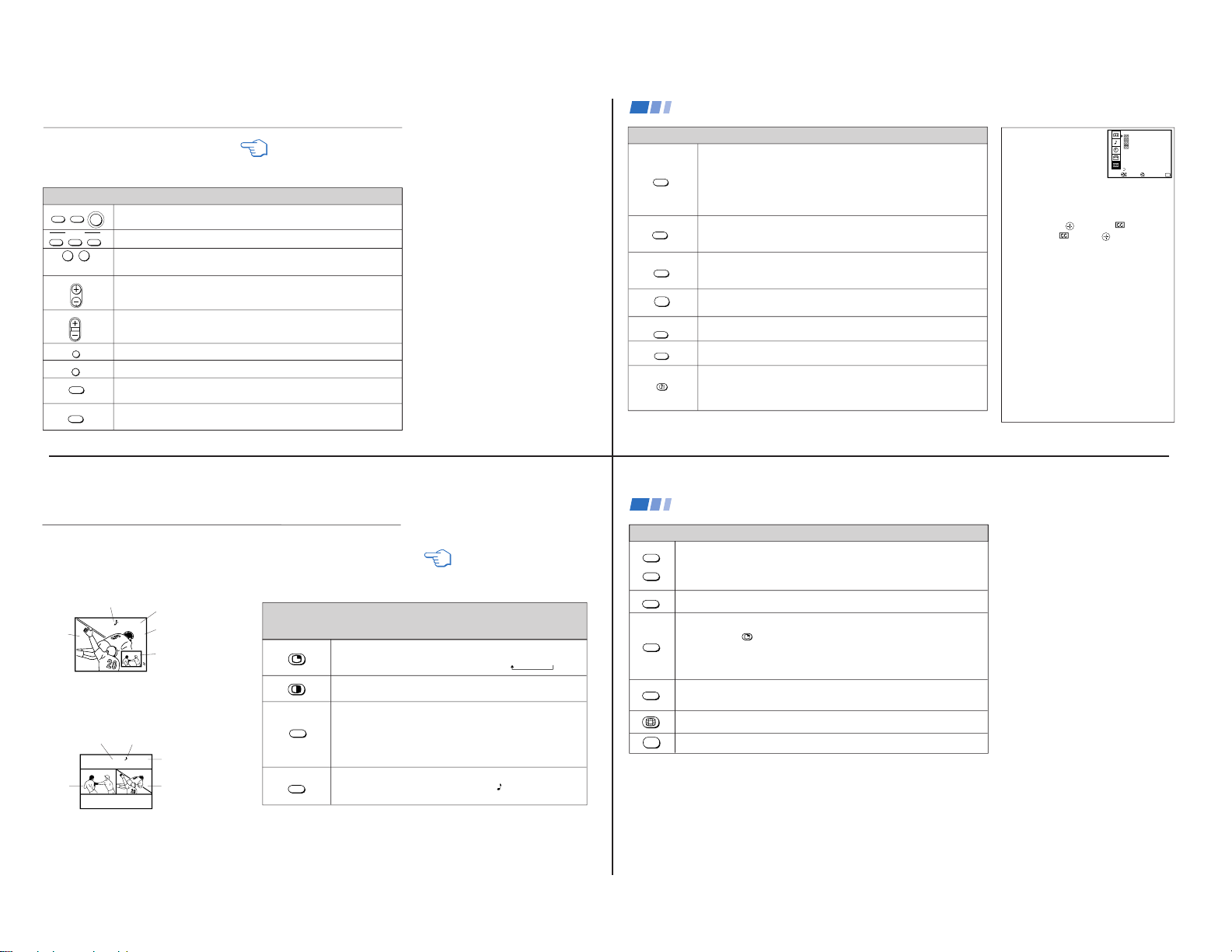
Watching the TV
Many TV features can be accessed directly
through the remote control. The following
chart will explain the function of some
buttons found on your remote control.
Using the White Labeled Buttons for TV Operations
Press when you want to turn equipment on and off.
Press when you want to control connected components with your remote control. (see
pages 31-33 for instructions on programming your remote control)
Use for direct channel selection. Press 0-9 to select a channel (for example, to select
channel 10, press 1 and 0), the channel will change after 2 seconds, or you can
press ENTER for immediate selection.
Press to scan through the channels.
Keeping the CH + or – pressed allows you to rapidly scan to the desired channel.
Press to adjust the volume.
Press to alternate or
jump
back and forth between two channels. The TV will jump
between the current channel and the last channel selected using the 0-9 buttons.
Press to mute the sound (“MUTING” will appear on the screen). Press again or press
VOL + to restore sound.
Press to freeze the picture.
Press again or press (OFF) to cancel.
Press repeatedly until the TV displays the approximate time in minutes (30, 60, or
90) that you want the TV to remain on before shutting off automatically.
Cancel by pressing until SLEEP OFF appears.
yellow labeled button
and ENTER
15
CAPTION VISION can be used for programs
that are broadcast with closed caption.
To access CAPTION VISION:
1 Press MENU.
2 Use the to scroll to
.
3 Select with the
button.
4 Choose a CAPTION VISION option.
5 Access CAPTION VISION/TEXT/XDS
through your DISPLAY button. (see left)
CC1, 2, 3 or 4
Shows you a printed version of the dialog or
sound effects of a program. (The mode should
be set to CC1 for most programs)
TEXT1, 2, 3 or 4
Shows you network/station information
presented using either half or the whole screen.
XDS (Extended Data Service)
Shows a network name, program name,
program length, and time of the show if the
broadcaster offers this service.
Note
• Poor reception of TV programs can cause
errors in CAPTION VISION and XDS.
Captions may appear with a white box or
other errors instead of intended text.
DISPLAY
TV/VIDEO
ANT
MTS
GUIDE
SYSTEM
OFF
TV/VTR
TV/DBS
Press repeatedly to step through available displays:
Status
Channel number, current time, channel caption (if set), and MTS mode (if SAP is
selected) are displayed. SAP indication disappears after three seconds.
Caption Vision/XDS
Closed captioning or XDS will be displayed on the screen if the broadcaster offers
these services. (see right)
To cancel the display, press DISPLAY repeatedly until DISPLAY OFF appears.
Press repeatedly to step through available video inputs:
TV, VIDEO 1, VIDEO 2, VIDEO 3 and VIDEO 4
If you select SKIP as a VIDEO LABEL in the SET UP menu, your TV will skip the
video input you selected. (see “VIDEO LABEL” on page 27)
Press to change between the VHF/UHF input and the AUX input. (For detailed
connection information, see “Cable box and cable” on page 4 or “Cable and
antenna” on page 3)
Press to change from VIDEO input to TV input.
Press to cycle through the Multi-channel TV Sound (MTS) options.
STEREO, SAP, MONO (see “MTS” on page 24)
Guide is a feature of DBS, refer to your DBS operating instructions.
Press to turn off the TV and all other equipment connected with S-Link. (see page 12)
Press when you are finished using a VCR and you want to switch to the TV input.
Your VCR power will remain on.
Press to select an audio option. (see “EFFECT” on page 24) Options:
TRUSURROUND Dolby Virtual
SIMULATED
EFFECT OFF
TV/DBS is a feature of DBS, refer to your DBS operating instructions.
Using the White Labeled Buttons for TV Operations
CAPTION VISION
(Closed Caption)
Move
MENU
Exit
MENU
CAPTION VISION
TEXT1
1
2
3
4
Select
TEXT2
TEXT3
TEXT4
XDS
Using your New TV (continued)
(AUX input)
16
7 6
10
6
The Picture-in-Picture (PIP) feature allows you
to view two channels simultaneously, one in
the full size “main” picture and one in a
smaller “window” picture.
The Picture-and-Picture (P&P) feature allows
you to view two channels simultaneously,
both in a reduced size screen. The main
picture will appear on the right.
Watching Two Programs at One Time — PIP/P&P (Twin View
TM
)
REFER TO THE ILLUSTRATION OF
THE REMOTE CONTROL ON THE
INSIDE FRONT COVER OF THIS
MANUAL AS YOU REVIEW THIS
CHART
Using the Yellow Labeled Buttons for PIP Operations
Some control buttons for PIP and P&P are located under
the cover on the top of the remote control.
Main
picture
The sound of the main
picture is received
Main picture
channel or inputsource mode
Window picture
channel or inputsource mode
Window
picture
Press to display a window picture (PIP).
Each time you press, the picture size will change (1/4 n1/9 n1/16).
Press (OFF) to remove the window picture.
Press to display right (main) and left pictures (P&P).
Press (OFF) to cancel.
Press repeatedly to step through available video inputs:
TV, VIDEO 1, VIDEO 2, VIDEO 3 and VIDEO 4
PIP will display the video source in the window picture.
P&P will display the video source in the left picture.
If you label one of your VIDEO inputs as SKIP, this video input will be
skipped. (see “VIDEO LABEL” on page 27)
Press to alternate sound between the main picture and the window picture
for PIP and the right and left picture for P&P. A
will appear for a few
seconds to indicate which picture is receiving sound.
TV/VIDEO
Main
picture
The sound of the right
picture is received
Right picture
channel or inputsource mode
Left picture channel
or input-source mode
Sub
picture
AUDIO
yellow labeled button
17
Using the Yellow Labeled Buttons for PIP Operations
Press to change the TV channel in the secondary picture.
For PIP, the channel in the window picture will change.
For P&P, the channel in the left picture will change.
Press to move the location of the window picture around the main picture.
This function works only for PIP.
Great for copying down phone numbers, addresses, recipes, etc.
For PIP: Press to freeze the main picture and remove the window picture.
Press
or FREEZE to resume PIP viewing.
Press (OFF) to cancel and resume normal TV viewing.
For P&P: Press to freeze both pictures.
Press again to resume P&P viewing or press (OFF) to cancel and resume
normal TV viewing.
Press to switch the audio and video of the main picture and the window picture for PIP, or
between the left and right pictures for P&P.
Press to access CHANNEL INDEX for direct channel selection. (see “Using CHANNEL
INDEX” on page 19)
Press to cancel PIP or P&P functions and return to normal viewing.
CH +
CH –
POSITION
FREEZE
SWAP
OFF
Notes
• The channel being received through the
AUX jack cannot be displayed as a
window picture.
• If one of the pictures received through
PIP/P&P is snowy, the entire screen may
appear snowy. In this case, skip the snowy
channel. (see “CHANNEL SKIP/ADD” on
page 26)
Using your New TV (continued)
18
KV-32XBR200/KV-36XBR200
— 9 —
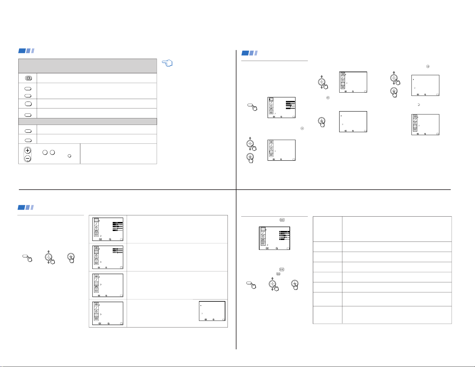
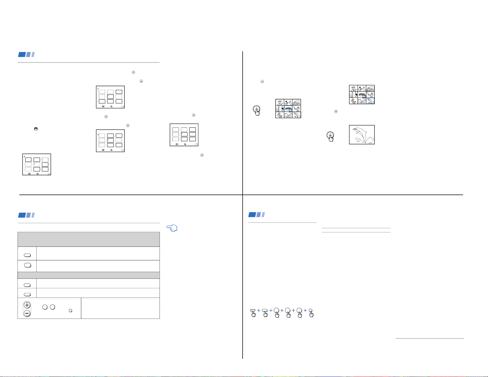
Learning Menu Selection
Use the MENU button to access a menu and
use the joystick to alter settings. Use the
following example, in which we activate the
CABLE, to learn how to modify settings.
1 Press the MENU button.
The main menu appears.
MENU
VIDEO
MODE: VIVID
PICTURE
HUE
COLOR
BRIGHTNESS
SHARPNESS
TRINITONE: HIGH
MENU
Exit
MENU
COLOR CORRECT: OFF
Move
Select
2 Press up or down on the joystick to
highlight the desired menu and press
to activate it.
SET UP
CHANNEL SET UP
FAVORITE CHANNEL
VIDEO LABEL
LANGUAGE: ENGLISH
TILT CORRECTION: 0
MENU
Exit
MENU
Move
Select
3 Press up or down on the joystick until the
cursor points to the desired option.
SET UP
CHANNEL SET UP
FAVORITE CHANNEL
VIDEO LABEL
LANGUAGE: ENGLISH
TILT CORRECTION: 0
MENU
Exit
MENU
Move
Select
4 Press
.
Options for your selection will be
displayed.
CHANNEL SET UP
MENU
Exit
MENU
CABLE: OFF
CHANNEL FIX: OFF
AUTO PROGRAM
CHANNEL SKIP / ADD
CHANNEL CAPTION
Move
Select
5 Press up or down on the joystick to make
your selection and press
to activate it.
CHANNEL SET UP
MENU
Exit
MENU
CABLE: ON
CHANNEL FIX: ON
AUTO PROGRAM
CHANNEL SKIP / ADD
CHANNEL CAPTION
Move
Select
When you are done with changes to the
selected menu, choose
MENU to return to
the main menu.
SET UP
CHANNEL SET UP
FAVORITE CHANNEL
VIDEO LABEL
LANGUAGE: ENGLISH
TILT CORRECTION: 0
MENU
Exit
MENU
Move
Select
Notes
• Pressing MENU on the remote control will
allow you to exit from the menus at any
time.
• If any menu items are “grayed out” press
the ANT button on your remote control
until a channel number appears.
Using your Menus
21
CH +
CH –
FREEZE
OFF
TV/VIDEO
Press to access CHANNEL INDEX.
Press again to access the next twelve receivable channels.
Press to cycle through the receivable channels one at a time.
Press to cancel the current operation and return to normal TV viewing.
Press to freeze the center picture.
Press again to cancel the frozen picture and resume normal center picture viewing.
ANT
Using the Yellow Labeled Buttons for CHANNEL INDEX Operations
Some control buttons are located under the cover
on the top of the remote control.
Using the White Labeled Buttons for Center Picture Operations
0
9
-
Press to cycle the center picture through the video inputs.
The surrounding channels will not change.
Press to replace the center picture with a channel received through the AUX input.
Press again to return to CATV input.
Press to select the channel for the center picture.
(see “Watching the TV” on pages 15-16)
and ENTER
CH
REFER TO THE ILLUSTRATION OF THE
REMOTE CONTROL ON THE INSIDE
FRONT COVER OF THIS MANUAL AS
YOU REVIEW THIS CHART
JUMP
or or
Using your New TV (continued)
20
VIDEO
MODE: VIVID
PICTURE
HUE
COLOR
BRIGHTNESS
SHARPNESS
TRINITONE: HIGH
MENU
Exit
MENU
COLOR CORRECT: OFF
Move
Select
AUDIO
TREBLE
BASS
BALANCE
EFFECT: OFF
MTS: STEREO
SPEAKER: ON
MENU
Exit
MENU
AUDIO OUT: VARIABLE
Move
Select
TIMER
DAYLIGHT SAVING: YES
CURRENT TIME SET
ON / OFF TIMER
CHANNEL BLOCK
MENU
Exit
MENU
––: – AM–
–––
Move
Select
SET UP
CHANNEL SET UP
FAVORITE CHANNEL
VIDEO LABEL
LANGUAGE: ENGLISH
TILT CORRECTION: 0
MENU
Exit
MENU
Move
Select
Quick start to the menus
The following is a guide to your menus.
For detailed information on using the remote
control to modify menu settings, refer to
“Learning menu selection” on page 21.
To select a menu:
Display
/ Highlight / Select
MENU
The VIDEO menu allows you to make adjustments to your picture settings.
It also allows you to customize the picture MODE based on the type of
program you are watching.
The AUDIO menu offers enhanced audio options such as listening to
second audio programming (SAP), or customizing the EFFECT of the
sound on your TV.
The TIMER menu sets the clock on your TV and allows you to program
your TV for scheduled viewing using the ON/OFF TIMER.
The SET UP menu provides several options for
setting up your channels, labeling your TV/VIDEO
inputs, and selecting the LANGUAGE of your menus.
The CHANNEL SET UP menu is a sub-menu which
provides further options for setting up your TV.
CHANNEL SET UP
MENU
Exit
MENU
CABLE: ON
CHANNEL FIX: OFF
AUTO PROGRAM
CHANNEL SKIP / ADD
CHANNEL CAPTION
Move
Select
Using your Menus (continued)
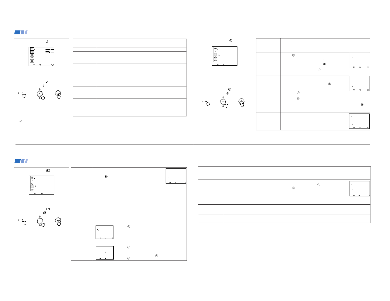
22
Using the VIDEO
Menu
VIDEO
MODE: VIVID
PICTURE
HUE
COLOR
BRIGHTNESS
SHARPNESS
TRINITONE: HIGH
MENU
Exit
MENU
COLOR CORRECT: OFF
Move
Select
For detailed information on using the remote
control to modify menu settings, refer to
“Learning Menu Selection” on page 21.
To select the VIDEO
menu:
Display
/ Highlight / Select
MENU
MODE
Customized picture
viewing
PICTURE
Picture contrast
BRIGHTNESS
Picture adjustment
COLOR
Color saturation
HUE
Color tones
SHARPNESS
Picture detail
TRINITONE
White intensity
adjustment
COLOR
CORRECT
Color ratio
adjustment
VIVID: Select for enhanced picture contrast and sharpness.
STANDARD: Select to display a standard picture.
MOVIE: Select to display a softer picture.
SPORTS: Select to display a bright picture.
You can alter the VIDEO menu settings (e.g., PICTURE, HUE) for each MODE.
Select each MODE individually and then press RESET to restore factory settings.
Adjust right to increase picture contrast and create more vivid color.
Adjust left to decrease picture contrast and soften the color.
Adjust right to brighten the picture.
Adjust left to darken the picture.
Adjust right to increase color intensity.
Adjust left to decrease color intensity.
Adjust right to increase the green tones.
Adjust left to decrease the green tones.
Adjust right to sharpen the picture.
Adjust left to soften the picture.
HIGH: Select to give the white colors a blue tint.
MEDIUM: Select to give the white colors a neutral tint.
NTSC STD: Select to give the white colors a red tint.
Select ON to emphasize reds and blues.
Select OFF to emphasize greens.
Adjustment
Bars
To restore the factory VIDEO settings
Press RESET on the remote control while the
VIDEO menu is selected.
}
23
KV-32XBR200/KV-36XBR200
— 10 —
DAYLIGHT
SAVING
Automatically adjusts
the time
CURRENT
TIME SET
Necessary for the
ON/OFF TIMER
ON/OFF TIMER
Wake up or
scheduled viewing
CHANNEL
BLOCK
Prevent access
to certain channels
Using the TIMER
Menu
TIMER
DAYLIGHT SAVING: YES
CURRENT TIME SET
ON / OFF TIMER
CHANNEL BLOCK
MENU
Exit
MENU
––: – AM–
–––
Move
Select
After setting the clock you can use the timer to
turn the TV on and off.
For detailed information on using the remote
control to modify menu settings, refer to
“Learning Menu Selection” on page 21.
To select the TIMER
menu:
Display /
Highlight / Select
MENU
Tip z
Set DAYLIGHT SAVING time before setting the clock.
Any loss of power will cause these settings to be erased.
Spring: Select YES to compensate for Daylight Saving Time.
The current time automatically moves ahead one hour.
Fall: Select NO at the end of Daylight Saving Time.
The current time moves back one hour.
1 Press , then press up or down on the joystick until the
current day is displayed, and press
.
2 Press up or down on the joystick until the current hour
and AM/PM is displayed, and press .
3 Press up or down on the joystick until the current
minute is displayed, and press .
The clock is set. Press MENU to exit.
1 Select a timer (1 or 2).
2 Press up or down on the joystick until the desired day
or range of days is displayed, and press .
3 Press up or down on the joystick until the time (hours and
minutes) that you want the TV to remain on is displayed,
and press
.
4 Press up or down on the joystick to set the time duration (maximum of 6 hours)
and press . TO CANCEL THE TIMER FUNCTION, PRESS RESET WHILE
THE ON/OFF TIMER MENU IS DISPLAYED.
5 Press up or down on the joystick to select the desired channel and press
.
The timer is now set. The TIMER indicator on your TV will be lit.
Press MENU to exit. Performing AUTO PROGRAM will erase all TIMER settings.
You will be able to block two channels for a period of up to 12 hours.
FOLLOW STEPS 1-5 OF ON/OFF TIMER ABOVE
To erase your CHANNEL BLOCK settings, press RESET
while in the CHANNEL BLOCK window. Performing AUTO
PROGRAM will erase your CHANNEL BLOCK settings.
CURRENT TIME SET
MENU
Exit
MENU
–––
––: ––AM
Move
Select
ON / OFF TIMER
1.
MENU
Exit
MENU
12: 0AM0SUN
2.
––––
––: ––AM–hCH
–––
––––
––: ––AM–hCH
–––
Select a position
––
––
Move
Select
CHANNEL BLOCK
1.
MENU
Exit
MENU
12: 0AM0SUN
2.
––––
––: ––AM hCH
–––
––––
––: ––AM–hCH
–––
––
––
Select a position
Move
Select
––
–
25
CHANNEL
SET UP
Basic set up options
for viewing
Using the SET UP
Menu
SET UP
CHANNEL SET UP
FAVORITE CHANNEL
VIDEO LABEL
LANGUAGE: ENGLISH
TILT CORRECTION: 0
MENU
Exit
MENU
Move
Select
For detailed information on using the remote
control to modify menu settings, refer to
“Learning Menu Selection” on page 21.
To select the SET UP
menu:
Display / Highlight
/ Select
MENU
If any menu items are “grayed out”, press the
ANT button on your remote control so that a
channel number appears.
Notes
• Your remote control can be programmed to
operate your cable box. (see page 33)
• After setting CABLE, you will need to run
AUTO PROGRAM.
• ON/OFF TIMER and CHANNEL BLOCK
settings will be erased when CHANNEL
FIX is set.
With the CHANNEL SET UP menu open:
1 Use the joystick to select the feature you want to change.
2 Press
to access the feature.
CABLE: Select ON if your TV is connected to a cable system.
(Easy Setup Guide will set CABLE to OFF automatically if a
cable channel is not available)
CHANNEL FIX: Press up or down on the joystick to set the TV's input to one of the
following options:
2-6:
When the cable box is connected to the VHF/UHF input and you do not want to switch
to AUX mode. Press DBS/CABLE (FUNCTION) and then CH +/– to change channels.
AUX 2-6: When a cable box is connected to AUX and a cable or antenna is connected
to VHF/UHF. You can alternate between the two inputs by pressing ANT.
VIDEO 1: When you have connected video equipment (e.g. A/V receiver) and you
want the TV input fixed to it. You will be able to alternate between video sources.
OFF: When you want to switch CHANNEL FIX off.
If the TV is in the AUX mode when you turn CHANNEL FIX off, press ANT to return to
regular (CATV) mode.
TIMER and CHANNEL BLOCK settings are erased when CHANNEL FIX is set.
AUTO PROGRAM: Allows the TV to program all receivable channels.
CHANNEL SKIP/ADD: With the CHANNEL SKIP/ADD window open:
1 Press
to SKIP or ADD (only one option will be available).
2 Select the desired channel.
CHANNEL CAPTION: Label up to 12 channels, with up to four letters each. With the
CHANNEL CAPTION window open:
1 Press and then press up or down on the joystick to select
the desired channel, and press
again.
2 Press up or down on the joystick to display the first letter or
number of the caption and press to select it.
3 Press
.
To erase a Caption, press RESET.
CHANNEL SKIP / ADD
SKIP
MENU
Exit
MENU
33
ADD
Use [ 0 – 9 ] or [ CH+ / – ]
to select the channel
Move
Select
CHANNEL CAPT I ON
MENU
Exit
MENU
33
––––
Move
Select
CHANNEL
CAPTION
CHANNEL SET UP
MENU
Exit
MENU
CABLE: ON
CHANNEL FIX: OFF
AUTO PROGRAM
CHANNEL SKIP / ADD
CHANNEL CAPTION
Move
Select
Using your Menus (continued)
26
Using the AUDIO
Menu
AUDIO
TREBLE
BASS
BALANCE
EFFECT: OFF
MTS: STEREO
SPEAKER: ON
MENU
Exit
MENU
AUDIO OUT: VARIABLE
Move
Select
For detailed information on using the remote
control to modify menu settings, refer to
“Learning Menu Selection” on page 21.
To select the AUDIO
menu:
Display /
Highlight / Select
MENU
TREBLE
BASS
BALANCE
EFFECT
Customize sound
effect based on the
program's audio type
MTS
Enjoy stereo,
bilingual and mono
programs
SPEAKER
Custom selection of
audio output source
AUDIO OUT
Easy control of
volume adjustments
Adjust left or right to decrease or increase higher pitched sound.
Adjust left or right to decrease or increase low pitched sounds.
Adjust left or right to emphasize left or right speaker volume.
TRUSURROUND: Produces a virtual surround effect for Dolby-surround encoded
programs.
SIMULATED: Adds a surround-like effect to mono programs.
OFF: Normal stereo or mono reception.
MTS: Press V or v to select one of the following options:
STEREO: Select when viewing a broadcast in stereo.
SAP: Select to listen to bilingual broadcast. (Non-SAP programs will be muted
when this feature is selected)
MONO: Select to reduce noise during stereo broadcasts for areas of weak
reception.
Quick MTS access: Press MTS on your remote control to cycle through
the MTS options.
ON: Select to listen to the sound from the TV speakers alone or the TV speakers
and a separate stereo system.
OFF: Select to turn off the TV speakers and listen to the TV's sound only through
external audio system speakers.
AUDIO OUT can only be set when SPEAKER is set to OFF.
VARIABLE: Sound output varies according to the TV settings.
Useful when you want to use your remote control to control the output of a
separate audio system.
FIXED: Sound output is held at a fixed level through your stereo.
Use your A/V receiver's remote control to adjust the volume.
To restore the factory AUDIO settings
Press RESET on the remote control while the
AUDIO menu is selected.
Tip z
Press for quick access to TRUSURROUND DOLBY
VIRTUAL.
}
Adjustment
Bars
Using your Menus (continued)
24
FAVORITE
CHANNEL
User's favorite
channels
VIDEO LABEL
Label connected
equipment for easy
recognition
(e.g. DBS, VHS, etc.)
LANGUAGE
User's preferred
language
TILT CORRECTION
Adjust your picture
The FAVORITE CHANNEL feature provides a multi-picture presentation to enable direct channel selection. (for details on how to set
up this feature, see “Setting and Selecting FAVORITE CHANNEL” on page 28)
The FAVORITE CHANNEL feature is not available for the AUX input.
With the VIDEO LABEL menu open:
1 Press up or down on the joystick to select the input mode you want to label and press
.
2 Press up or down on the joystick to select the label and press .
VIDEO LABEL Options:
VIDEO 1/2/3: VHS, 8mm, BETA, LD, GAME, DBS, DVD, WEB, RECEIVER, DTV, SKIP
VIDEO 4: DVD, DTV, SKIP
If you select SKIP, your TV will skip this connection when you scan through video sources using the TV/VIDEO button.
When VIDEO LABEL is set to WEB, the screen will darken, creating an ideal picture for WebTV viewing.
Select from available languages to display all menus in your language of choice.
Use this feature to correct any tilt of the picture.
Press up or down on the joystick to select a correction between +5 and –5 andpress
.
VIDEO LABEL
VIDEO
MENU
Exit
MENU
1 :
VIDEO 2 :
VIDEO 3 :
VIDEO 4 :
VHS
VIDEO 2
VIDEO 3
VIDEO 4
Move
Select
27
KV-32XBR200/KV-36XBR200
— 11 —
The FAVORITE CHANNEL feature provides
a multi-picture presentation to enable direct
channel selection.
Your FAVORITE CHANNEL options can be
set automatically or manually.
The factory setting for FAVORITE
CHANNEL is AUTO. When FAVORITE
CHANNEL is set to AUTO, the last eight
channels selected with the 0-9 buttons will be
set as FAVORITE CHANNEL options.
Setting FAVORITE CHANNEL
manually
1 Select FAVORITE CHANNEL from the
SET UP menu.
The FAVORITE CHANNEL menu will
appear. If you set CHANNEL CAPTION,
captions (e.g. CNN, HBO) for the channels
selected will display. (see “CHANNEL
CAPTION” on page 26)
MENU
FAVORITE CHANNEL
MODE : AUTO
Exit
MENU
1.
2
CNN
3
2.
HBO
2
6
3.
ABC
2
9
8.
4
3
4.
MTV
3
5
7.
NBC
1
56.2 8
5.
CBS
1 1
Move
Select
2 Select MODE and press
.
Press up or down on the joystick to
display MANUAL and press
.
MENU
FAVORITE CHANNEL
MODE : MANUAL
Exit
MENU
Select a position
1.
2
CNN
3
2.
HBO
2
6
3.
ABC
2 9
8.
4
3
4.
MTV
3
5
7.
NBC
1
56.2 8
5.
CBS
1 1
Move
Select
3 Press down on the joystick to select 1 and
press
.
Press up or down on the joystick to select
a channel and press .
MENU
FAVORITE CHANNEL
MODE : MANUAL
Exit
MENU
Select a position
1.
2
ESP
5
2.
HBO
2
6
3.
ABC
2
9
8.
4
3
4.
MTV
3
5
7.
NBC
1
56.2 8
5.
CBS
1 1
1
Move
Select
You have now selected a favorite channel
for position 1.
4 Use the joystick to select other FAVORITE
CHANNEL positions and program other
favorite channels.
5 Press MENU when you are finished.
Your favorite channels are now ready to
use.
Resetting FAVORITE CHANNEL
choices
You have the option of returning to the
FAVORITE CHANNEL screen to adjust any
of your favorite channel choices.
Simply proceed as described in “Setting
FAVORITE CHANNEL manually” (skip step
2 if MANUAL is already selected). When you
reach step 3, select the position you want to
change and press
. Press RESET to clear
the channel for that position.
MENU
FAVORITE CHANNEL
MODE : MANUAL
Exit
MENU
Select a channel
2.
HBO
2
6
3.
ABC
2
9
8.
4
3
4.
MTV
3
5
7.
NBC
1
56.2 8
5.
CBS
1 1
1.
___
Move
Select
Press up or down on the joystick to select a
new channel and press
.
Press MENU when you are done.
Note
• Channels received through the VHF/UHF
input and the AUX input cannot be
viewed within the FAVORITE CHANNEL
menu at the same time.
Setting and Selecting FAVORITE CHANNEL
Using your Menus (continued)
28
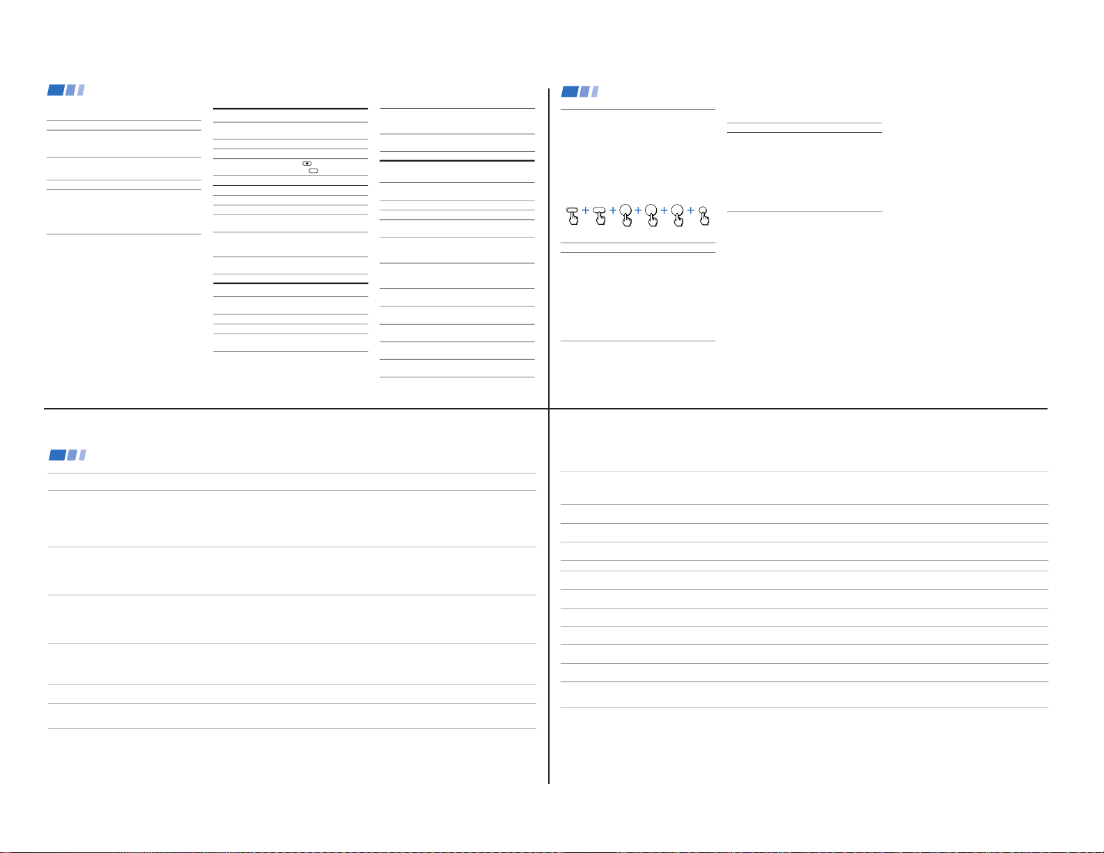
2 When you find a channel that you wish to
view, use the joystick to move the yellow
frame to that picture.
The sound of the picture surrounded by
the yellow frame will be received.
Reciipe
flour - - - - 2
sugar - - - 1/2
salt - - - - - 1/2
butter - - - 1
3 Press
to select the channel.
The selected channel will be retrieved and
displayed for normal viewing.
Using FAVORITE CHANNEL
You can use the FAVORITE CHANNEL
feature to display multiple channels for direct
selection.
1 Press once.
The current channel will be displayed in
the center of the screen surrounded by
your eight favorite channels.
Reciipe
flour - - - - 2
sugar - - - 1/2
salt - - - - - 1/2
butter - - - 1
A yellow frame will appear to indicate
current channel selection. The TV will
continually update each of the surrounding
pictures.
Notes
• You cannot move the yellow frame until
all of the surrounding pictures appear.
• If one of the pictures received through
FAVORITE CHANNEL is snowy, the
entire screen may appear snowy. In this
case, erase the snowy channel using
CHANNEL SKIP/ADD. (see “CHANNEL
SET UP” on page 26)
29
or or
FREEZE
OFF
TV/VIDEO
Press to freeze the center picture.
Press again to cancel the frozen picture and resume normal FAVORITE CHANNEL
viewing.
Press to cancel the current operation and return to normal TV viewing.
ANT
Using the Yellow Labeled Buttons for FAVORITE CHANNEL Operations
Some control buttons are located under the cover
on the top of the remote control.
Using the White Labeled Buttons for Center Picture Operations
Press to cycle the center picture through the video inputs.
The surrounding channels will not change.
Press to replace the center picture with a channel received through the AUX input.
Press again to return to CATV input.
Press to select the channel for the center picture.
(see “Watching the TV” on pages 15-16)
Setting and Selecting FAVORITE CHANNEL (continued)
REFER TO THE ILLUSTRATION OF THE
REMOTE CONTROL ON THE INSIDE
FRONT COVER OF THIS MANUAL AS
YOU REVIEW THIS CHART
0 9
-
and ENTER
CH
JUMP
Using your Menus (continued)
30
Setting the Manufacturer's Code
You can use the supplied remote control to
operate Sony or non-Sony video equipment
that has an infrared sensor.
1 Set the VTR 1/2/3/DVD/MDP switch to
the position through which you would
like to access the video equipment.
The following Sony equipment is preset to
each position of the switch:
VTR1 (303) Beta, ED Beta VCRs
VTR2 (302) 8 mm VCR
VTR3 (301) VHS VCR
DVD/MDP (751) DVD Player
2 Press CODE SET, VTR/DVD (FUNCTION),
the 0-9 buttons to enter the manufacturer's
code number (see the following chart), then
press ENTER.
For example, to operate a Sony 8mm VCR:
If the remote control doesn’t work
• Try repeating the set up procedures using
the other codes listed for your equipment.
VCR code numbers
Manufacturer Code
Sony 301, 302, 303
Aiwa 338, 344
Admiral (M. Ward) 327
Audio Dynamic 314, 337
Bell & Howell (M. Ward) 330, 343
Broksonic 319, 317
Canon 309, 308
Citizen 332
Craig 315, 302, 332
Criterion 315
Curtis Mathes 304, 338, 309
Daewoo 341, 312, 309
DBX 314, 336, 337
Dimensia 304
Emerson 319, 320, 316, 317, 318,341
Fisher 330, 334, 335, 333
Funai 338
General Electric 329, 304, 309
Go Video 322
Goldstar 332
Hitachi 306, 304, 305,338
Instant Replay 309, 308
JC Penney 309, 305, 304, 330, 314, 336, 337
JVC 314, 336, 337, 345, 346, 347
Kenwood 314, 336, 332, 337
LXI (Sears) 332, 305, 333, 334, 330, 335, 338
Magnavox 308, 309, 310
Marantz 314, 336, 337
Marta 332
Memorex 309, 335
Minolta 305, 304
Mitsubishi/MGA 323, 324, 325, 326
Multitech 325, 338, 321
NEC 314, 336, 337
Olympic 309, 308
Optimus 327
Panasonic 308, 309, 306, 307
Pentax 305, 304
Philco 308, 309
Philips 308, 309, 310
Pioneer 308
Quasar 308, 309, 306
RCA/PROSCAN 304, 305, 308, 309, 311,
329, 312, 313, 310
Realistic 309, 330, 328, 335, 324, 338
Sansui 314
Singer 315
Samsung 322, 313, 321
Sanyo 330, 335
Scott 312, 313, 321, 335, 323, 324,325, 326
Sharp 327, 328
Shintom 315
Signature 2000 (M. Ward) 338, 327
Sylvania 308, 309, 338, 310
Symphonic 338
SV2000 338
Tashiro 332
Tatung 314, 336, 337
Teac 314, 336, 338, 337
Technics 309, 308
Toshiba 312, 311
Wards 327, 328, 335, 331, 332
XR-1000 315
Yamaha 330, 314, 336, 337
Zenith 331
2
3
0
CODE SET
ENTER
VTR/DVD
FUNCTION
Operating Video Equipment
31
KV-32XBR200/KV-36XBR200
— 12 —
Operating an MDP using the remote control
To turn On/Off
To play
To stop
To pause
Operating a DVD Player using the remote
control
To turn On/Off
To play
To stop
To pause
To step through
different tracks of
an audio disc
To step through
different chapters of
a video disc
To display the Title
menu
To display the DVD
software menu
To select tracks
directly
To display the menu
(Set up)
To move the cursor
in the menu
To scan the picture
To search a chapter
forward or backward
Press ) or 0 during
playback. Release to resume
normal playback.
Press CH +/–.
Press VTR/DVD (POWER).
[Green Button]
Press (.
Press p.
Press P. Press again to
resume normal playback.
Press ) to step forward or
0 to step backward.
Press CH+ to step forward or
CH– to step backward.
Press TITLE.
Press DVD MENU.
Press 0-9 buttons and ENTER.
Press MENU.
Move the joystick in the
corresponding direction.
Press VTR/DVD (POWER).
[Green Button]
Press (.
Press p.
Press P. Press again to
resume normal playback.
Operating a VCR using the remote control
To turn On/Off
To select a channel
To change channels
To record
To play
To stop
To fast forward
To rewind the tape
To pause
To scan the picture
To change input
mode
MDP code numbers
Manufacturer Code
Sony 701
Panasonic 704, 710
Pioneer 702
DVD Player code numbers
Manufacturer Code
Sony 751
Panasonic 753
Pioneer 752
RCA 755
Toshiba 754
Tips z
• In some rare cases, you may not be able to operate your
non-Sony video equipment with the supplied remote
control. In this case, please use the equipment's own
remote control.
• When you remove the batteries, the code number may
revert to the factory setting.
To operate video equipment
1 Set the VTR1/2/3/DVD/MDP switch to
the position through which you would
like to access the video equipment.
2 Use the VCR/DVD/MDP buttons
indicated in the following tables.
Press VTR/DVD (POWER).
[Green Button]
Press the 0 – 9 buttons.
Press CH +/–.
Press (REC) while
pressing (upper left).
Press (.
Press p.
Press ).
Press 0.
Press P. Press again to
resume normal playback.
Press ) or 0 during
playback. Release to resume
normal playback.
Press TV/VTR.
Operating Video Equipment (continued)
32
DBS receiver code numbers
Manufacturer
Sony
General Electric
Hitachi
Hughes
Panasonic
RCA/PROSCAN
Toshiba
To operate the TV
Press TV (FUNCTION). Then use the TV
control buttons to control the TV.
For more details on operating the
cable box or DBS receiver
Refer to the operating instructions supplied
with the equipment.
If the remote control doesn’t work
• First, try repeating the set up procedures
using the other codes listed for your
equipment.
Setting the Manufacturer's Code
You can program the supplied remote control
to operate a cable box or DBS receiver.
Press CODE SET, DBS/CABLE (FUNCTION),
the 0-9 buttons to enter the manufacturer's
code number (see the following chart), then
press ENTER.
For example, to operate a Sony DBS receiver:
Cable box code numbers
Manufacturer
Hamlin/Regal
Jerrold/G. I.
Oak
Panasonic
Pioneer
Scientific Atlanta
Tocom
Zenith
Code
222, 223, 224, 225, 226
201, 202, 203, 204, 205,
206, 207, 208, 218
227, 228, 229
219, 220, 221
214, 215
209, 210, 211
216, 217
212, 213
Code number
801 (preset code for
remote control)
802
805
804
803
802, 808
806, 807
Tips z
• If more than one code number is listed, try entering
them one by one until you come to the correct code for
your equipment.
• If you enter a new code number, the code number you
previously entered at that setting is erased.
• In some rare cases, you may not be able to operate
your equipment with the supplied remote control. In
this case, use the equipment’s supplied remote
control.
• Whenever you remove the batteries — to replace
them, for example — if too much time is taken, the
code numbers may revert to the factory setting.
1
8
0
CODE SET
ENTER
DBS/CABLE
FUNCTION
Operating a Cable Box or DBS Receiver
33
Troubleshooting
• First, turn the TV on. Then, while pressing the RESET button on the remote control, press the POWER button on the TV. The TV will
turn itself off, then back on. When the TV turns on again, all settings will be reset, and the Easy Setup Guide will appear.
• If your TV does not turn on, and a red light keeps flashing, your TV may need service. Call your local Sony service center.
• Make sure the power cord is plugged in.
• Operate with the buttons on the TV and the remote control.
• Check to see if the TV/VIDEO setting is correct: when watching TV, set to TV, and when watching video tapes, set to VIDEO 1, 2, 3 or 4.
• Try another channel. It could be station trouble.
• Perform Easy Setup Guide again using the SET UP button to return to the factory preset condition. (see “To perform AUTO SET UP
again” on page 14)
• Batteries could be weak. Replace the batteries.
• Press TV (FUNCTION) when operating your TV.
• Make sure the TV’s power cord is connected securely to the wall outlet.
• Locate the TV at least 3-4 feet away from fluorescent lights.
• Check the S-Link connection. (see page 12)
• Make sure the batteries are inserted correctly.
• Adjust PICTURE in the VIDEO menu. (see “PICTURE” on page 23)
• Adjust BRIGHTNESS in the VIDEO menu. (see “BRIGHTNESS” on page 23)
• Check antenna/cable connections.
• Perform Easy Setup Guide again using the SET UP button to return to the factory preset condition. (see “To perform AUTO SET UP
again” on page 14)
• When VIDEO LABEL is set to WEB, the screen will darken, creating an ideal picture for WebTV viewing. (see "VIDEO LABEL" on page 28)
• Press MUTING so that “MUTING” disappears from the screen. (see “MUTING” on page 16)
• Check the MTS setting in the AUDIO menu. (see “MTS” on page 24)
• Make sure SPEAKER is set to ON in the AUDIO menu. (see “SPEAKER” on page 24)
• Perform Easy Setup Guide again using the SET UP button to return to the factory preset condition. (see “To perform AUTO SET UP
again” on page 14)
• Make sure CABLE is OFF in the SET UP menu. (see “CHANNEL SET UP” on page 26)
• Use AUTO PROGRAM to add receivable channels that are not presently in TV memory. (see “CHANNEL SET UP” on page 26)
• Adjust the COLOR in the VIDEO menu. (see “COLOR” on page 23)
• Perform Easy Setup Guide again using the SET UP button to return to the factory preset condition. (see “To perform AUTO SET UP
again” on page 14)
To reset the TV to factory
settings
No picture (screen not lit), no
sound
Remote control does not operate
Dark, poor or no picture (screen
lit), good sound
Good picture, no sound
Cannot receive upper channels
(UHF) when using an antenna
No color
34
Only snow and noise appear on
the screen
Dotted lines or stripes
TV is fixed to one channel
Double images or ghosts
Cannot operate menu
Cannot receive any channels
when using cable tv
Cannot gain enough volume when
using a cable box
TV malfunctions when using the
S-Link function
CHANNEL INDEX does not display
all available channels
FAVORITE CHANNEL does not
display your choices
Some video sources do not
appear when you press TV/VIDEO
Recording through MONITOR OUT
does not function properly when
recording in PIP or P&P mode
• Check the CABLE setting in the SET UP menu. (see “CHANNEL SET UP” on page 26)
• Check the antenna/cable connections.
• Make sure the channel is broadcasting programs.
• Press ANT to change the input mode. (see “ANT” on page 16)
• Adjust the antenna.
• Move the TV away from noise sources such as cars, neon signs, or hair-dryers.
• Try turning CHANNEL FIX off. (see “CHANNEL SET UP” on page 26)
• Use AUTO PROGRAM to add receivable channels that are not presently in the TV memory. (see “CHANNEL SET UP” on page 26)
• Use a highly directional outdoor antenna or a cable (when the problem is caused by reflections from nearby mountains or tall
buildings).
• If the item you want to choose appears in gray, you cannot select it. Your TV may be receiving video input. Try pressing TV/VIDEO.
• Make sure CABLE is ON in the SET UP menu. (see “CHANNEL SET UP” on page 26)
• Use AUTO PROGRAM to add receivable channels that are not presently in TV memory. (see “CHANNEL SET UP” on page 26)
• Increase the volume at the cable box. Then press TV (FUNCTION) and adjust the TV’s volume.
• Check the S-Link connection. (see on page 12)
• Make sure CABLE is ON in the SET UP menu. (see “CHANNEL SET UP” on page 26)
• Use AUTO PROGRAM to add receivable channels that are not presently in the TV memory. (see “CHANNEL SET UP” on page 26)
• Verify that MODE is set to MANUAL in the FAVORITE CHANNEL menu. (see “Setting FAVORITE CHANNEL manually” on page 28)
• Ensure that VIDEO LABEL is not set to SKIP. (see “VIDEO LABEL” on page 27)
• MONITOR OUT will not record both images in PIP or P&P. Only the main picture will be recorded.
• If you are recording the main picture and you switch to the sound of the sub picture using the AUDIO button, the main picture will
be recorded with sound from the other program.
If, after reading these operating instructions, you have any additional questions related to the use of your Sony television, please call our Direct
Response Center at 1-800-222-SONY (7669) (customers in the U.S. only) or (416) 499-SONY (7669) (customers in Canada only).
35
KV-32XBR200/KV-36XBR200
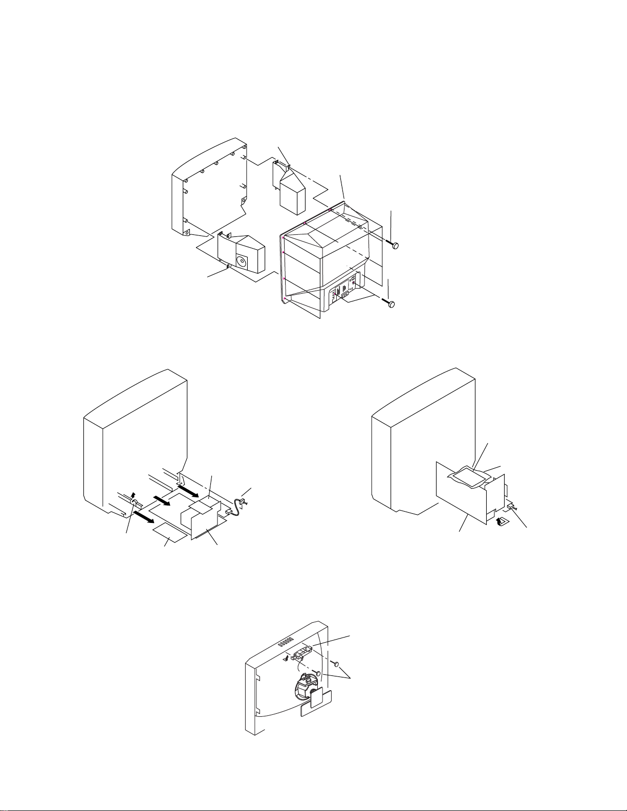
SECTION 2
DISASSEMBLY
2-1. REAR COVER AND SPEAKER REMOVAL
5 Speaker (L)
4 Rear cover
3 Ten screws
(+BVTP 4x16)
KV-32XBR200/KV-36XBR200
6 Speaker (R)
2-2. CHASSIS ASSY REMOVAL
G board
Power cord
Claw
K board
Chassis assembly
1 Two screws
(+BVTP 3x12)
2-3. SERVICE POSITION
A board
K board
Insulator
G board
2-4. CONTROL ASSY REMOVAL
HX Bracket
Two screws
(+BVTP 4x16)
— 13 —
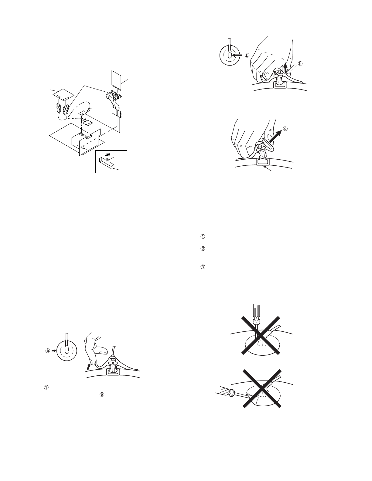
KV-32XBR200/KV-36XBR200
2-5. EXTENSION CABLE
Extension cable 18 pin
3-702-541-01
BX board
3-702-558-01
PX board
Use your thumb to pull the rubber cap firmly in
the direction indicated by arrow b.
Extension cable 11 pin
3-702-564-01
Claw
Connector
• ANODE-CAP REMOV AL
WARNING:
is disconnected. To avoid electrical shock, discharge CRT before
attempting to remove the anode cap. Short between anode and
coated earth ground strap of CRT.
NOTE: After removing the anode, short circuit the anode of the
picture tube and the anode cap to either the metal chassis, CRT
shieldor carbon painted on the CRT.
High voltage remains in the CRT even after the power
• REMOVAL PROCEDURES
Anode button
3 When one side of the rubber cap separates from
the anode button, the anode-cap can be removed
by turning the rubber cap and pulling it in the di-
rection of arrow c.
• HOW TO HANDLE AN ANODE CAP
Do not use sharp objects which may cause damage
to the surface of the anode-cap.
Do not squeeze the rubber covering too hard to avoid
damaging the anode-cap. A material fitting called a
shatter-hook terminal is built into the rubber.
Do not force turn the foot of the rubber cover. This
may cause the shatter-hook terminal to protrude and
damage the rubber.
Turn up one side of the rubber cap in the direction
indicated by the arrow .
— 14 —

2-6. PICTURE TUBE REMOVAL
WARNING Before removing
anode cap:
High voltage remains in the CRT even
after the power is disconnected.
8 Four screws
(Tapping screw 7)
5 C board
KV-32XBR200/KV-36XBR200
3 G board
2 Chassis assy
4 K board
T o avoid electrical shock, discharge CR T before attempting to remove the anode cap.
Short between anode and coated earth
ground strap of CRT.
Coated earth
ground strap
6 Neck assy
7 Deflection yoke
0 Picture tube
1 Anode cap
9 Cushion
— 15 —

KV-32XBR200/KV-36XBR200
SECTION 3
SET-UP ADJUSTMENTS
The following adjustments should be made when a
Perform the adjustments in order as follows:
complete realignment is required or a new picture
tube is installed.
1. Beam Landing
2. Convergence
These adjustments should be performed with rated
power supply voltage unless otherwise noted.
Set the controls and switch as follows unless
3. Focus
4. Screen (G2)/White Balance
Note: Test Equipment Required
otherwise noted:
1. Color Bar Pattern Generator
VIDEO MODE: STANDARD
PICTURE control ................. 100%
BRIGHTNESS control ......... 50%
2. Degausser
3. DC Power Supply
4. Digital Multimeter
3-1. BEAM LANDING
Preparation:
• Input a white pattern signal.
• Face the picture tube in a East or West direction to reduce the influence of geomagnetism.
NOTE: Do not use the hand degausser because it magnetizes the CRT .
1. Input white pattern from pattern generator.
2. Loosen the deflection yoke mounting screw, and set
the purity control to the center as shown below:
3. Input green pattern from pattern generator.
4. Move the deflection yoke backward, and adjust with
the purity control so that green is in the center and
red and blue are even on both sides.
BR
G
6. Switch over the raster signal to red and blue and confirm
the condition.
7. When the position of the deflection yoke is determined,
tighten it with the deflection yoke mounting screw.
8. When landing at the corner is not right, adjust by using
the disk magnets.
Purity control corrects this area.
a
d
Disk magnets or
rotatable disk magnets
correct these areas
(a-d).
b
b
c
Deflection yoke positioning
corrects these areas.
5. Move the deflection yoke forward, and adjust so that
the entire screen becomes green.
— 16 —
a
c
d
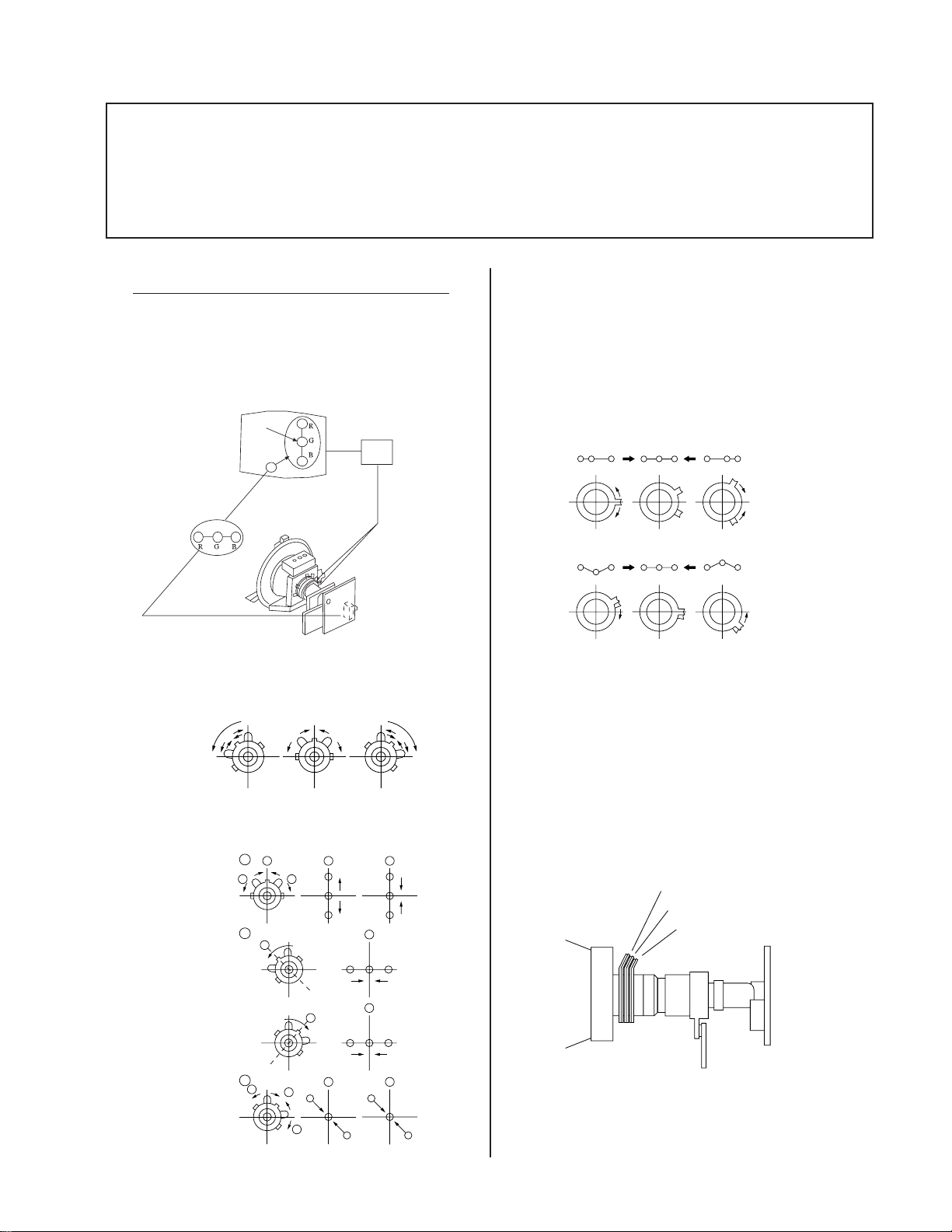
3-2. CONVERGENCE
Preparation:
• Before starting, perform FOCUS, V. LIN and V. SIZE adjustments.
• Set BRIGHTNESS control to minimum.
• Input dot pattern.
KV-32XBR200/KV-36XBR200
(1) Vertical and Horizontal Static Convergence
1. Adjust V. STAT magnet to converge red, green and blue
dots in the center of the screen. (Vertical movement
Adjust HSTAT RV to converge.
Center dot
V.STAT
Magnet
RV1761
H.STAT
Tilt the V. STAT magnet and adjust static convergence
to open or close the V. STAT magnet.
Operation of BMC (Hexapole) Magnet
The respective dot positions resulting from moving each
magnet interact, so perform adjustment while tracking.
Use the VSTAT tabs to adjust the red, green, and blue dots
so they line up at the center of the screen (move the dots in
a horizontal direction.)
RG B
RGB RGB
RGB
RGB
RGB
Y Separation Axis Correction Magnet Adjustment
1. Input cross-hatch pattern, adjust PICTURE to
minimum and BRIGHTNESS to normal.
2. When the V. STAT magnet is moved in the direction of
arrow a and b, red, green, and blue dots move as
shown below:
b
1
2
3
a
a
b
a
b
b
R
b
a
B
G
R
a
G
a
RG B
b
BG R
B
B
b
B
G
R
b
G
R
2. Adjust the deflection yoke upright so it touches the
CRT.
3. Adjust so that the Y separation axis correction magnet
on the neck assembly is symmetrical from top to
bottom (open state).
Purity
BMC magnet
H/V START magnet
4. Return the deflection yoke to its original position.
— 17 —
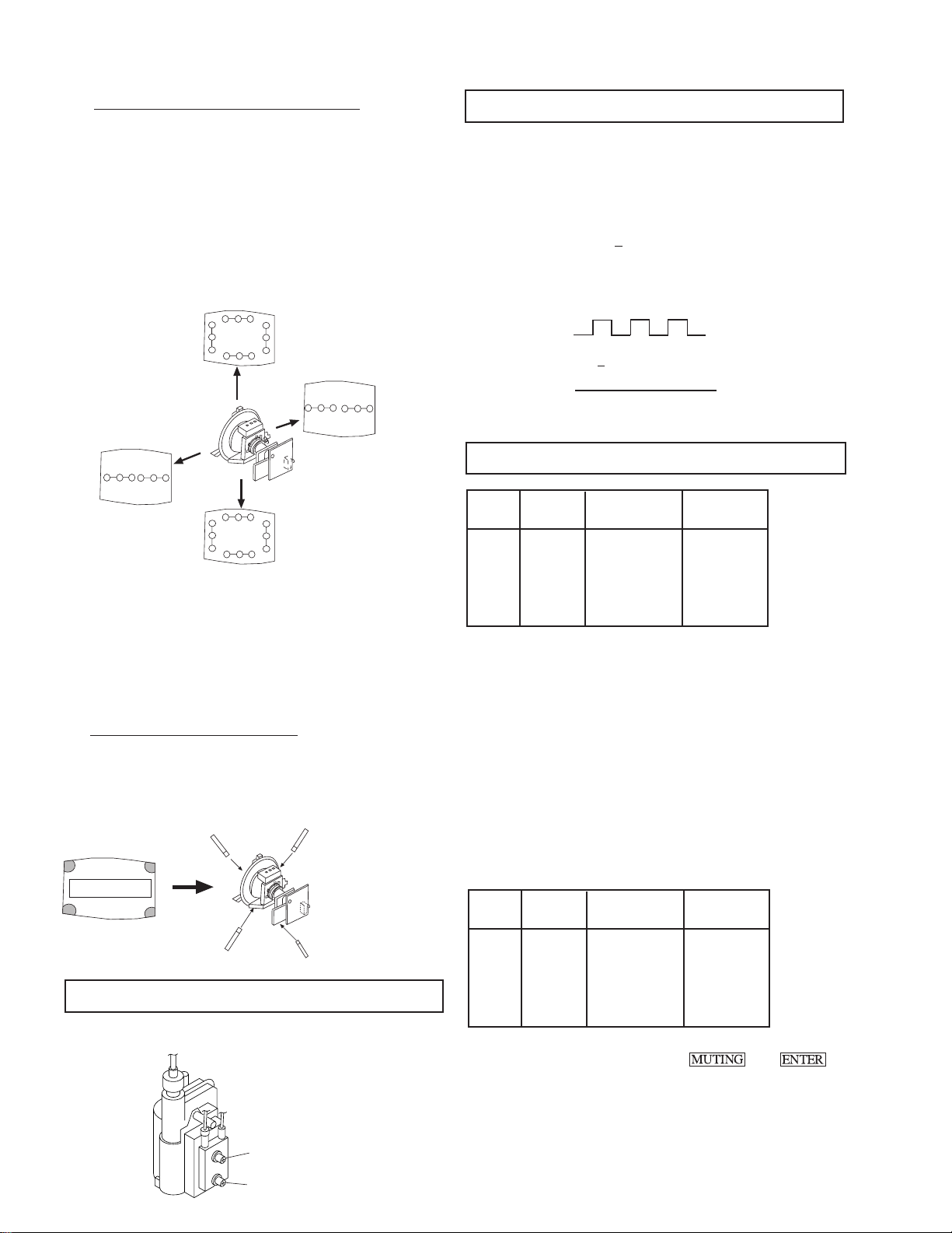
KV-32XBR200/KV-36XBR200
( 2 ) Dynamic Convergence Adjustment
• Before starting, perform Horizontal and Vertical
Static Convergence Adjustment.
1. Slightly loosen deflection yoke screw.
2. Remove deflection yoke spacers.
3. Move the deflection yoke for best convergence as
shown below:
B
B G R
R
G
G
R
R G B
B
R G BB G R
R G B B G R
B
R
R G B
G
G
R
B
B G R
4. Tighten the deflection yoke screw.
5. Install the deflection yoke spacers.
6. Adjust vertical red and blue convergence with
VLT (VR).
7. Adjust horizontal red and blue convergence with
YCH (VR).
(3) Screen-corner Convergence
Affix a permalloy assembly to correspond with the
misconverged areas:
b
b
a-d: screen-corner
misconvergence
c
a
d
a
3-4. SCREEN (G2)
1. Input dot pattern from the pattern generator.
2. Set the PICTURE and BRIGHT controls at normal.
3. Adjust S BRT, G CUT, B CUT in service mode with an
oscilloscope so that voltages on the red, green, and blue
cathodes are 170V
+ 2 V DC.
4. Observe the screen and adjust SCREEN (G2) VR on FBT
to obtain the faintly visible background of dot signal.
170 + 2 V DC
GND
N
NN
NN
180 V dc
NN
NN
N
N
NN
NN
pedestal
3-5. WHITE BALANCE ADJUSTMENTS
NO. Disp. Item Average
18 GDRV Green Drive 31
19 BDRV Blue Drive 25
20 GCUT Green Cut-off 3
21 BCUT Blue Cut-off 10
29 SBRT Sub Bright 30
1. Input an entire white signal.
2. Set to Service adjustment Mode.
3. Set the PICTURE and BRIGHT to minimum.
4. Adjust with SBRT if necessary.
5. Select GCUT and BCUT with 1 and 4 .
6. Adjust with 3 and 6 for the best white balance.
7. Set the PICTURE and BRIGHT to maximum.
8. Select GDRV and BDRV with 1 and 4 .
9. Adjust with 3 and 6 for the best white balance.
10. After adjusting the white balance, adjust the white balance
video four as follows:
NO. Disp. Item
Calculate the
Average Data
d
3-3. FOCUS
Adjust FOCUS control for best picture.
FOCUS
SCREEN
c
22 4GDR Green Drive GDRV+2
23 4BDR Blue Drive BDRV +1
24 4GCT Green Cut-off GCUT
25 4BCT Blue Cut-off BCUT-1
11. Write into the memory by pressing then .
— 18 —
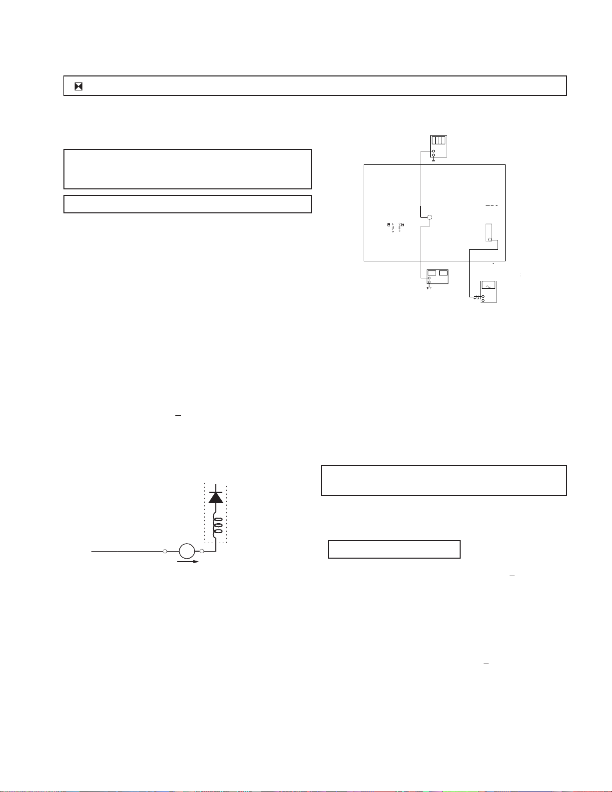
dejital
ge
KV-32XBR200/KV-36XBR200
R530, R531 CONFIRMATION METHOD (HOLD-DOWN CONFIRMATION) AND READJUSTMENTS
Always perform the following adjustments when replacing the
following components marked with a ] mark on the schematic
diagram:
A BOARD: IC351, IC501, D519, D520, D521, C531,
SAFETY RELATED ADJUSTMENTS
C532, R387, R529, R530, R531, R532,
R533, R550, T503
SECTION 4
digital multimeter
multimeter
+
-
G BOARD: IC643, R661
Step 1 Preparation before Confirmation
Turn the POWER switch ON.
Input a white signal and set the PICTURE and BRIGHT
controls to maximum.
Confirm that the voltage at the check terminal of TP85 is
more than 23.0 V DC when the set is operating normally.
At AC input: 120.0 ± 2.0 VAC
Step 2
Input a white signal and verify that I ABL is within the
specified range:
At AC input: 120.0 ± 2.0 VAC
2175 + 100 µA.
T503
FBT
T504
FBT
ammeter
3.0 mA DC
range
ABL
+
I ABL
-
A
T503
R530
R530
R531
R531
DC Power Supply
dc power supply
TP85
TP85
+
-
T503
FBT
FBT
11
ammeter
ammeter
3mA dc ran
3mA DC range
A
+
-
1T40
A BOARD - CONDUCTOR SIDE
Step 5
Confirm that a voltage of more than 23.0 V DC appears
between TP85 and ground.
At AC input: 120.0 ± 2.0 VAC
B+ VOLT AGE CONFIRMATION
AND ADJUSTMENT
Always perform the following adjustments when replacing the
following components marked with ] on the schematic diagram:
G BOARD: IC643, R661
1) Using Variac, apply AC input voltage: 130
+ 2.0 VAC
Step 3
Record the voltage between TP85 and ground.
Step 4
Using an external DC power supply, apply voltage
between TP85 and ground.
Increase the voltage gradually and confirm that the
holdown works (raster disappears) at lower than the
voltage recorded in Step 3.
Lower than 27.24 V DC
At AC input: 120.0 ± 2.0 VAC
2) Input a monoscope signal.
3) Set the PICTURE control and the BRIGHTNESS control
to initial reset value.
4) Confirm the voltage of G BOARD CN641 between
pin 1 to ground is less than 136.5 + 1.0 V DC.
5) If step 4 is not satisfied, replace the R661and repeat the
above steps.
— 19 —

KV-32XBR200/KV-36XBR200
SECTION 5
CIRCUIT ADJUSTMENTS
ELECTRICAL ADJUSTMENT BY REMOTE COMMANDER
Use Remote Commander (RM-Y144) to perform the following circuit adjustments:
NOTE : Test Equipment Required:
1. Pattern Generator
2. Frequency Counter
3. Digital Multimeter
4. Audio OSC
(1) Setting the Service Adjustment Mode
SERVICE MODE PROCEDURE
1. Standby mode. (Power off)
2.
on the Remote
Commander. (Press each button within a second.)
SERVICE ADJUSTMENT MODE IN
Register Item
Disp.
Item
Data Item
Device Item
SERVICE VP VPOS 30
1000 0
(Item)
data
3. The CRT displays the item being adjusted.
4. Press
5. Press
6. Press
2
or 5 on the Remote Commander to select the device item.
or on the Remote Commander to select the item.
or on the Remote Commander to change the
data.
7. To recover the latest values, press "0" then
8. Press
SERVICE ADJUSTMENT MODE MEMORY
then to write into memory.
(2) Memory Write Confirmation Method
1. After adjustment, pull out the plug from the AC outlet,
then replace the plug in the AC outlet again.
2. Turn the power switch ON and set to Service Mode.
3. Call the adjusted items again to confirm they were
adjusted.
(3) Adjust Buttons and Indicator
MUTING
(Write into memory)
DISPLAY
MUTING
SYSTEM
OFF
(Service mode)
1
(Item up)
2
(Device item up)
4
(Item down)
1 3
4 5 6
7 8 9
JUMP
OFF
TV/DBS GUIDE
8
(Initialize)
.
VOL (+)
(Service mode)
CODE SET
VTR/DVD DBS/CABLE
MUTING
VTR/DVE DBS/CABLE TV
TV/VIDEO ANT
DISPLAYSLEEP
2
ENTER
0
MENU
RESET
VTR 1 2 3 DVD/MDP
POWER
TV
POWER
(Service mode)
3
(Data up)
6
(Data down)
5
´
MTS
CHVOL
RM-Y144
ENTER
0
(Read of memory)
SERVICE VP VPOS 30
1000 0
9. Press
SERVICE WRITE
1000 0000
Green
then on the Remote Commander to reset.
10. Turn set off and on to exit.
Red
Carry out step 8 when adjusting
IDs 0 to 4 and when replacing
and adjusting IC102.
TV
RM-Y144
— 20 —

(4) Service Data
No. Register Description Data Adj/Fix Initial Avg.
KV-32XBR200/KV-36XBR200
Name Range Data
VP CXA2095AS
1 VPOS V-Position 0-63 Adjust 20 21
2 VSIZ V-Size 0-63 Adjust 20 38
3 PVSZ V-Size 0-63 Adjust 20 31
4 VCOM V-Compensation 0-3 Fix 1 1
5 VLIN V-Linearity 0-15 Adjust 7 12
6 VSCO S-Correcttion 0-15 Adjust 7 8
7 HPOS H-Position 0-15 Adjust 7 14
8 HSIZ H-Size 0-63 Adjust 18 23
9 PHSZ H-Size 0-63 Adjust 20 9
10 PAMP PIN-Compensation 0-63 Adjust 31 19
11 UPIN Upper-CornerPin 0-15 Adjust 7 6
12 LPIN Lower-CornerPin 0-15 Adjust 7 8
13 PPHA Pin-Phase 0-15 Adjust 7 3
14 AFC AFC 0-3 Fix 2 2
15 VBOW AFC-Bow 0-15 Adjust 7 8
16 VANG AFC-Angle 0-15 Adjust 7 3
17 REF Reference-Position 0-3 Fix 2 2
18 GDRV Green-Drive 0-63 Adjust 31 31
19 BDRV Blue-Drive 0-63 Adjust 31 25
20 GCUT Green-Cutoff 0-15 Adjust 7 3
21 BCUT Blue-Cutoff 0-15 Adjust 7 10
22 4GDR Green-Drive 0-63 Adjust 31 29
23 4BDR Blue-Drive 0-63 Adjust 31 24
24 4GCT Green-Cutoff 0-15 Adjust 7 8
25 4BCT Blue-Cutoff 0-15 Adjust 7 11
26 SCON Sub-Contrast 0-15 Adjust 7 6
27 SHUE Sub-Hue 0-15 Adjust 7 6
28 SCOL Sub-Color 0-15 Adjust 7 7
29 SBRT Sub-Brightness 0-63 Adjust 31 30
30 SSHP Sub-Sharpness 0-15 Fix 7 7
31 CDM2 Count Down Mode2 “0, 1” Fix 1 1
32 DPIX Dynamic-Picture “0, 1” Fix 1 1
33 Y-DC DC-Transmission “0, 1” Fix 1 1
34 ABLM ABL “0, 1” Fix 1 1
35 NOTC CromaTrap “0, 1” Fix 0 0
36 CROM CromaTrap-Adjust 0-15 Fix 7 7
37 TOT TOT-Filter “0, 1” Fix 1 1
38 PREL Pre/Over-Shoot 0-3 Fix 0 0
39 SHPF Sharpness-f0 0-3 Fix 2 2
40 RON Red-Off “0, 1” Fix 1 1
41 GON Green-Off “0, 1” Fix 1 1
42 BON Blue-Off “0, 1” Fix 1 1
43 CDMD V-Countdown “0, 1” Fix 0 0
44 HBSW HBLKSW “0, 1” Fix 0 0
45 LBLK Left Blanking 0-15 Fix 7 7
46 RBLK Right Blanking 0-15 Fix 7 7
AP BH3856
47 SVOL Sub-Volume 0-15 Fix 0 0
48 SBAL Sub-Balance 0-15 Fix 7 7
49 SBAS Sub-Bass 0-15 (Fix by Model) 7 7
50 STRE Sub-Treble 0-15 (Fix by Model) 7 7
TS TC9447F
51 TB0U B0h Upper 8bit 0-255 Fix 0 0
52 TB0L B0h Lower 8bit 0-255 Fix 0 0
53 TB1U B1h Upper 8bit 0-255 Fix 0 0
54 TB1L B1h Lower 8bit 0-255 Fix 0 0
55 TB2U B2h Upper 8bit 0-255 Fix 57 57
56 TB2L B2h Lower 8bit 0-255 Fix 0 0
— 21 —
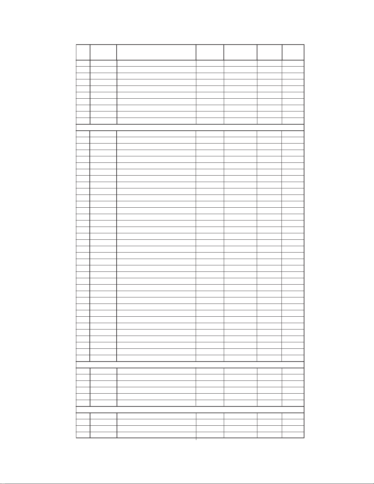
KV-32XBR200/KV-36XBR200
No. Register Description Data Adj/Fix Initial Avg.
Name Range Data
57 TBFU BFh Upper 8bit 0-255 Fix 166 166
58 TBFL BFh Lower 8bit 0-255 Fix 0 0
59 TC0U C0h Upper 8bit 0-255 Fix 90 90
60 TC0L C0h Lower 8bit 0-255 Fix 0 0
61 TC1U C1h/C7h Upper 8bit 0-255 Fix 79 49
62 TC1L C1h/C7h Lower 8bit 0-255 Fix 0 0
63 MADU ADh Upper 8bit 0-255 Fix 64 64
64 MADL ADh Lower 8bit 0-255 Fix 0 0
65 MB0U B0h Upper 8bit 0-255 Fix 92 92
66 MB0L B0h Lower 8bit 0-255 Fix 0 0
3D uPD6488
67 CGAN CGAIN “0, 1” Fix 1 1
68 AVAP AVAPON “0, 1” Fix 1 1
69 MS MS0/MS1 0-2 Fix 0 0
70 YDLL YDELAY-L 0-7 Fix 2 2
71 HRD8 HRD08 “0, 1” Fix 0 0
72 HRD7 HRD00-07 0-255 Fix 12 12
73 DYCO DYCOR 0-15 Fix 5 5
74 DYGA DYGAIN 0-15 Fix 8 8
75 DCCO DCCOR 0-15 Fix 3 3
76 DCCG DCGAIN 0-15 Fix 7 7
77 VTR0 VTR0/VTR1 0-2 Fix 0 0
78 VTRH VTRH 0-2 Fix 2 2
79 VTRR VTRR 0-15 Fix 7 7
80 SELJ SELJ “0, 1” Fix 1 1
81 HSDR HSDR 0-15 Fix 7 7
82 WSCO WSCOR 0-15 Fix 15 15
83 LDSR LDSREF 0-15 Fix 7 7
84 WSD1 WSDR1 0-15 Fix 15 15
85 WSD2 WSDR2 0-15 Fix 15 15
86 VAPG VAPGAIN 0-7 Fix 4 4
87 VAPI VAPINV 0-31 Fix 15 15
88 MDTE MDTES “0, 1” Fix 0 0
89 YTM8 YTM87 “0, 1” Fix 0 0
90 DYTR DYTRAP “0, 1” Fix 1 1
91 VHG VHG 0-3 Fix 3 3
92 YH87 YH87 “0, 1” Fix 0 0
93 YSG YSG “0, 1” Fix 1 1
94 YTG YTG 0-3 Fix 1 1
95 VTMR YTMREF 0-15 Fix 12 12
96 VHRE VHREF 0-15 Fix 11 11
97 YT1R YT1REF 0-15 Fix 2 2
98 CT2Y CT2YT “0, 1” Fix 0 0
99 CTG CTG 0-3 Fix 1 1
100 CTMR CTMREF 0-15 Fix 10 10
101 CT2R CT2REF 0-15 Fix 10 10
102 CT1R CT1REF 0-15 Fix 7 7
PI T A1226N
103 SHPR Sharpness 0-127 Fix 59 59
104 SRTS SRT Start Position “0, 1” Fix 3 3
105 GIRE Gamma Start Point 0-3 Fix 3 3
106 GCUR Gamma Curve “0, 1” Fix 0 0
107 RS RS 0-7 Fix 0 0
108 RTC RTC 0-7 Fix 4 4
DC CXA2026AS
109 DCSF DCSHIFT 0-63 Fix or Adjust 32 41
110 UYBW UYBOW 0-63 Fix 31 31
111 LYBW LYBOW 0-63 Fix 31 31
112 HAMP HAMP 0-63 Fix or Adjust 23 9
— 22 —
KV-32XBR200/KV-36XBR200
No. Register Description Data Adj/Fix Initial Avg.
Name Range Data
113 UCBW UCBOW 0-63 Fix 14 14
114 LCBW LCBOW 0-63 Fix 14 14
115 UMBH UMBH 0-63 Fix 15 15
116 LMBH LMBH 0-63 Fix 15 15
117 PWM PWM 0-63 Fix 63 63
118 HTLT HTILT 0-63 Fix 63 63
119 UTLT UTILT 0-63 Fix 63 63
120 LTLT LTILT 0-63 Fix 63 63
121 HDTY HDUTY 0-4 Fix 3 3
122 TOFF TILT OFF “0, 1” Fix 1 1
123 DAC0 DAC0 0-255 Fix 255 255
124 DAC1 DAC1 0-255 Fix 255 255
PP SAB9076
125 SMT6 SMART6 “0, 1” Fix 1 1
126 SKP6 SKIP6 “0, 1” Fix 0 0
127 BGHP BGhfp 0-15 Adjust 7 8
128 BGVP BGvfp 0-15 Adjust 8 8
129 MAHP MAhfp 0-15 Adjust 6 6
130 MAVP MAvfp 0-255 Adjust 24 24
131 SAHP SAhfp 0-15 Fix 3 3
132 SAVP SAvfp 0-255 Fix 24 24
133 VPED PedestV 0-15 Fix 14 0
134 UPED PedestU 0-15 Fix 14 0
135 MDEC “16h, bit 0-4” 0-32 Fix 18 18
136 SDEC “15h, bit 0-4” 0-32 Fix 16 16
137 DISS “17h, bit 0-7” 0-126 Fix 2 2
138 BSIZ — 0-255 Fix 34 34
139 POFH — 0-15 Fix 11 11
140 POFV — 0-15 Fix 6 6
141 DHPS Display H Position Start 0-15 Fix 4 5
142 P&PV “SDhf , MDhfp under P&P” 0-255 Fix 62 62
143 BBR0 — 0-3 Fix 1 1
144 BCL0 — 0-7 Fix 7 7
145 BBR2 — 0-3 Fix 2 2
146 BCL2 — 0-7 Fix 6 6
147 BBR3 — 0-3 Fix 0 0
148 BCL3 — 0-7 Fix 7 7
SP SDA9288
149 PYSD Select Delay 0-15 Fix 3 3
150 PIPH PIP H-Position 0-127 Fix 78 78
151 PIPV PIP V-Position 0-63 Fix 18 18
152 PYDL PIP Y-delay 0-7 Fix 0 0
153 PHDL H-pulse delay 0-15 Fix 3 3
154 PMVD Main V-pulse delay 0-31 Fix 16 16
155 PIVD Inset V-pulse delay 0-31 Fix 22 22
156 PCON Inset Contrast 0-15 Fix 7 7
157 FRMY Frame Y 0-15 Fix 7 7
158 CHRI Input Polarity “0, 1” Fix 1 1
159 CHRO Output Polarity “0, 1” Fix 1 1
160 IPER Inset Pedestal R-Y 0-15 Fix 0 0
161 IPEB Inset Pedestal B-Y 0-15 Fix 0 0
162 PCPS CLPS BIt Control “0, 1” Fix 0 0
163 PCPF CLPFIX BIt Control “0, 1” Fix 0 0
164 PSEL SELDOWN Bit Control “0, 1” Fix 1 1
165 PPLL PLL Filter Bits 0-3 Fix 1 0
166 PVNR PVNR bit “0, 1” Fix 0 1
MC CXA2019
167 MHUE HUE 0-63 Fix 26 26
168 MCOL COLOR 0-63 Fix 35 35
— 23 —

KV-32XBR200/KV-36XBR200
No. Register Description Data Adj/Fix Initial Avg.
Name Range Data
169 MSCO SUB CONT 0-15 Adjust 7 7
170 MSCL SUB COLOR 0-15 Adjust 7 7
171 MSHU SUB HUE 0-15 Adjust 7 7
172 MTOT TOT ON “0, 1” Fix 1 1
173 MTRP TRAP ON “0, 1” Fix 0 0
174 MTRA CTRAPADJ 0-15 Fix 7 7
175 MCD2 CD MODE2 “0, 1” Fix 1 1
176 MFSC FSC OUT “0, 1” Fix 1 1
177 MYDR Y DRIVE 0-31 Fix 22 22
178 MVPE V PED 0-15 Adjust 7 7
179 MUPE U PED 0-15 Adjust 7 7
180 MRVP RV PED 0-15 Fix 0 0
181 MRUP RU PED 0-15 Fix 0 0
182 MDCT DC TRAN 0-7 Fix 0 0
183 MRYD RY DRIVE 0-31 Fix 31 31
184 MPRE PRE OVER 0-3 Fix 0 0
185 MRUD RU DRIVE 0-31 Fix 15 15
186 MRVD RV DRIVE 0-31 Fix 15 15
187 MDLY DELAY 0-3 Fix 0 0
188 MSCR SCP BGR 0-3 Fix 1 1
189 MSCF SCP BGF 0-3 Fix 1 1
IC CXA2019
190 ICYC CV/YC “0, 1” (Fix by Model) 1 1
191 IHUE HUE 0-63 Fix 24 24
192 ICOL COLOR 0-63 Fix 37 37
193 ISCO SUB CONT 0-15 Adjust (FD7) 6 7
194 ISCL SUB COLOR 0-15 Adjust (FD7) 7 7
195 ISHU SUB HUE 0-15 Adjust (FD7) 7 7
196 ITOT TOT ON “0, 1” Fix 1 1
197 ITRP TRAP ON “0, 1” Fix 0 0
198 ITRA CTRAPADJ 0-15 Fix 7 7
199 ICD2 CD MODE2 “0, 1” Fix 1 1
200 IYDR Y DRIVE 0-31 Fix 24 24
201 IVPE V PED 0-15 Adjust (FD7) 7 7
202 IUPE U PED 0-15 Adjust (FD7) 7 7
203 IRVP RV PED 0-15 Fix 0 0
204 IRUP RU PED 0-15 Fix 2 2
205 IDCT DC TRAN 0-7 Fix 0 0
206 IRYD RY DRIVE 0-31 Fix 31 31
207 IPRE PRE OVER 0-3 Fix 0 0
208 IRUD RU DRIVE 0-31 Fix 15 15
209 IRVD RV DRIVE 0-31 Fix 15 15
210 IDLY DELAY 0-3 Fix 0 0
211 ISCR SCP BGR 0-3 Fix 1 1
212 ISCF SCP BGF 0-3 Fix 1 1
DA CXA1315
213 RTCO DAC0 (Rotation Coil) 0-63 Fix 32 32
214 2HUE DAC1 (CXA2039 Hue) 0-63 Adjust 28 28
215 2COL DAC2 (CXA2039 COL) 0-63 Adjust 31 42
CC CXP858
216 CRIL CRI Count Low 0-15 Fix 2 2
217 CFLD “Feild Count for VCR FF,REV” 0-15 Fix 5 5
218 CCDI CCD INT 0-7 Fix 3 3
219 CRIP CRI & Parity 0-7 Fix 4 4
220 CRIT CRI Time Constant 0-3 Fix - 1
221 CSB1 Sync Slice Bias 1 0-3 Fix 3 3
222 CSB2 Sync Slice Bias 2 0-7 Fix 4 4
223 CREP CRI Signal End Position 0-256 Fix 142 142
224 CDSD Data Start Delay 0-31 Fix 8 8
— 24 —

KV-32XBR200/KV-36XBR200
No. Register Description Data Adj/Fix Initial Avg.
Name Range Data
225 CCDS Caption Data Threshold 0-31 Fix 9 9
226 CHMK p8_hmask 0-63 Fix 42 42
227 CHSY p8_hsyc 0-255 Fix 136 136
OP CXP858/CXA2025 Color
228 DISP OSD Position 0-63 (Touch Up) 1 13
229 PDPS PIP Display Position Start 0-63 (Touch Up) 1 35
230 PDP0 PIP Display Position 0 0-3 (Touch Up) 1 1
231 PDP1 PIP Display Position 1 0-7 (Touch Up) 4 4
232 PDP2 PIP Display Position 2 0-7 (Touch Up) 4 3
233 KILS Color Killer SW “0, 1” - 1 1
ID 0-5
234 ID-0 ID-0 (Language: 89/25/9) 0-255 Fix by Model 89 89
235 ID-1 ID-1 0-255 Fix 63 63
236 ID-2 D-2 (Audio Effect) 0-255 Fix by Model 63 63
237 ID-3 ID-3 (Front Control: 0/64) 0-255 Fix by Model 0 0
238 ID-4 ID-4 (Auto Shut Off: 139/171) 0-255 Fix by Model 139 139
239 ID-5 ID-5 0-255 - 137 137
ID 6-7
240 ID-6 ID-6 (PinP/P&P) 0-255 Fix by Model 38 38
241 ID-7 ID-7 0-255 Fix 0 0
SERVICE IDO 25
Note: Items 1-241 show adjustment order.
— 25 —

KV-32XBR200/KV-36XBR200
(5) Feature ID Map
ON-VKtseD0DI1DI2DI3DI4DI5DI6DI7DI
002RBX23-VKSU9836360931371830
002RBX23-VKDNC9836360931371830
002RBX63-VKSU9836360931371830
002RBX63-VKDNC9836360931371830
SUB BRIGHT ADJUSTMENT (SBRT)
1. Set to Service adjustment Mode.
2. Input a gray scale pattern signal.
3. Set the PICTURE to minimum, and BRIGHT to normal.
4. Select SBRT with
and .
5. Adjust SUB BRIGHT level with and so that the stripe
second from the right is faintly visible.
6. Write into the memory by pressing
white
second from the right
then .
black
SUB CONTRAST ADJUSTMENT (SCON)
1. Input a 75% color-bar signal.
2. Set to VIDEO mode = STANDARD, COLOR = minimum,
PICTURE = 100%.
GON = 0 (OFF), BON = 0 (OFF).
3. Set to Service adjustment Mode and Connect an oscilloscope
pin 1 of CN351 on A Board.
4. Select SCON with
5. Adjust with
and for the 1.90 ± 0.05Vp-p of level.
6. Write into the memory by
and .
then .
SUB HUE, SUB COLOR ADJUSTMENT (SHUE, SCOL)
1. Input a color bar signal.
2. Set to Service adjustment Mode and set to
VIDEO mode = STANDARD
PICTURE = 100%
COLOR = 50%
HUE = 50%.
3. Connect an oscilloscope to CN351 Pin 3 of A Board.
4. Select SHUE and SCOL with
5. Adjust with
and for the V1 = V4 (SCOL) and V2 = V3
and .
(SHUE).
6. After adjustment write SHUE data 1 step down and SCOL
data 2 steps up.
7. Write into the memory by pressing then .
V1
V2 V3
V4
H. SIZE ADJUSTMENT (HSIZ)
1. Input a monoscope signal.
2. Set to Service adjustment Mode.
3. Select HSIZ with and .
4. Adjust with
5. Write into the memory by pressing
and for the best Horizontal size.
then .
H. SIZE
White
1.90±
0.05Vp-p
Black
— 26 —
 Loading...