

Sony KV-29SD1, KV-32S20, KV-29V20M, KV-27S20, KV-34RS20C Operating Instructions Manual
...
Trinitron Color TV
Operating Instructions
KV-27S20
KV-27V20
KV-29PS1
KV-29RS20
KV-29RS20C
KV-29SD1
KV-29V20M
KV-32520
KV-34RS20C
©1996 by Sony Corporation
To prevent fire or shock hazard, do not
expose the television to rain or moisture.
RISK OF ELECTRIC SHOCK
DO NOT OPEN
ATTENTION
RISQUE DE CHOC ELECTRIQUE,
NE PAS OUVRIR
PRECAUCION
RtESGO DE CHOQUE ELECTRICO
NO ABRIR
CAUIION: IOHEDUCL IrtLHIUt_U} LLkblRIUSHUGK,
DO NOT REMOVE COVER (OR BACK).
NO USER-SERVICEABLE PARTS INSIDE.
REFER SERVICING TO QUALIFIED SERVICE PERSONNEL,
I Ins symbol is intended to alert tile uber to the
presence of uninsulated "dangerous voltage"
within the product's enclosure that may be of
sufficient magnitude to constitute a risk of
electric shock to persons.
This symbol is intended to alert the user to the
presence of important operating and
maintenance (servicing) instructions in the
literature accompanying the appliance.
CAUTION
To prevent electric sho_k, do not use this polarized AC plug with
an extension cord, receptacle or other outlet unless the blades can
be fully inserted to prevent blade exposure.
Precautions
Safety
• Operate the TV only on 120 V AC (except KV-29RS20C/
34RS20C).
• Operate the TV only on 220 V AC (KV-29RS20C/34RS20C only).
• One blade of the plug is wider than the other for safety
purposes and will fit into the power outlet only one way. If
you are unable to insert the plug fully into the outlet, contact
your dealer (except KV-29RS20C/34RS20C).
• Should any liquid or solid object fall into the cabinet, unplug
the TV and have it checked by qualified personnel before
operating it any further.
• Unplug the TV from the wall outlet if you are not going to
use it for several days or more. To disconnect the cord, pull it
out by the plug. Never pull the cord itself.
For details concerning safety precautions, see the supplied leaflet
"IMPORTANT SAFEGUARDS."
Installing
• To prevent intcxn,d hc,a build-up, do m_t block the
ventilation openings.
• Do not install the TV in a hot or humid place, or in a plm
subject to excessive dust or mechanical vibration.
CAUTION
When using TV games, computers, and similar products with
your TV, keep the brightness and contrast functions at low
settings. If a fixed (non-moving) pattern is left on the screen for
long periods of time at a high brightness or contrast setting, the
image can be permanently imprinted onto the screen. These
types of imprints are not covered by your warranty because they
are the result of misuse.
NOTIFICATION
This equipment has been tested and found to comply with the
limits for a Class B digital device pursuant to Part 15 of the FCC
Rules. These limits are designed to provide reasonable protection
against harmful interference in a residential installation. This
equipment generates, uses, and can radiate radio frequency
energy and, if not installed and used in accordance with the
instructions, may cause harmful interference with radio
communications. However, there is no guarantee that
interference will not occur in a particular installation. If this
equipment does cause harmful interference to radio or television
reception, which can be determined by turning the equipment off
and on, the user is encouraged to try to correct the interference
by one or more of the following measures:
- Reorient or relocate the receiving antennas.
- Increase the separation between the equipment and receiver.
- Connect the equipment into an outlet on a circuit different
from that to which the receiver is connected.
- Consult the dealer or an experienced radio/TV technician for
help.
You are cautioned that any changes or modifications not
expressly approved in this manual could void your
authority to operate this equipment.
This document is for the remote commander RM- Y135.
MODEL: KV-27S20/27V20/29PS1/ 29RS20 /29RS20C/29SD1/
29V20M/32S20/34RS20C
Please keep this notice with the instruction manual.
Note on Caption Vision
This television receiver provides display of television closed
captioning in accordance with § 15.119 of the FCC rules.
Note to CATV system installer
This reminder is provided to call the CATV system installer's
attention to Article 820-40 of the NEC that provides guidelines for
proper grounding and, in particular, specifies that the cable
ground shall be connected to the grounding system of the
building, as close to the point of cable entry as practical.
Use of this television receiver for other than private viewing of
programs broadcast on UHF or VHF or transmitted by cable
companies for the use of the general public may require
authorization from the broadcaster, cable company and / or
program owner.
Owner's Record
The model and serial numbers are located at the rear ot the TV.
Record these numbers in the spaces provided below. Refer to
them whenever you call upon your Sony dealer regarding this
product.
Model No.
Serial No.
4 Welcome!
4 Checking your model number
I III
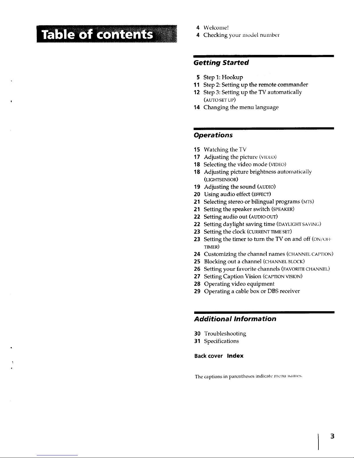
Getting Started
5 Step 1: Hookup
11 Step 2: Setting up the remote commander
12 Step 3: Setting up the TV automatically
(AUTO SET UP)
14 Changing the menu language
Operations
15 Watching the TV
17 Adjusting the picture (VIDLO)
18 Selecting the video mode (VIDEO)
18 Adjusting picture brightness automatically
(LIGHTSENSOR)
19 Adjusting the sound (AUDIO)
20 Using audio effect (EFFECT)
21 Selecting stereo or bilingual programs (MTS)
21 Setting the speaker switch (SPEAKER)
22 Setting audio out (AUDIOOUT)
22 Setting daylight saving time (DAYLIGHTSAV1NG)
23 Setting the clock (CURRENT TIME SET)
23 Setting the timer to turn the TV on and off (oN/oJ+
TIMER)
24 Customizing the channel names (CHANNEL CAPT1ON)
25 Blocking out a channel (CHANNEL BLOCK)
26 Setting your favorite channels (FAVORITE CHANNEL)
27 Setting Caption Vision (CAPTION VISION)
28 Operating video equipment
29 Operating a cable box or DBS receiver
Additional Information
30 Troubleshooting
31 Specifications
Back cover Index
The captions in parentheses indicate menu nameb.
I 3
lhank yt,u lt,l purchasing the Sony Trinitron _'_Color
TV. Here are some of the features you will enjoy with
your TV:
• On-screen menus that let you set the picture quality,
sound, and other settings.
• Surround system that simulates the sound quality of
a concert hall or movie theater (KV-27S20/29PS1/
29RS20/29RS20C/29SD1/32S20/34RS20C only).
• SRS (SOUND RETRIEVAL SYSTEM) that allows
you to receive realistic sound that recaptures audio
"clues" originally present but masked in the
recording process so that the action seems to
happen all around you (KV-27V20/29V20M only).
• LightSensor TMthat automatically adjusts the
brightness of the picture (KV-27V20/29V20M only).
'lhe instruction> Ill thLs n_anual aIc lor tt_e nmc _deia
listed on the cover. Before you start reading, check
your model number by looking at the rear of your TV.
The KV-27S20 is the model used for illustration
purposes. Any differences in operation are clearly
indicated in the text, for example, "KV-27S20 only."
Instructions in this manual are based on the remote
commander. You can also use the controls on the TV if
they have the same name as those on the remote
commander.
Getting Started
Although y_u can ubc eithei al_ indool or outdoox
antenna with your TV, we recommend that you
connect an outdoor antenna or a cable TV system to get
better picture quality.
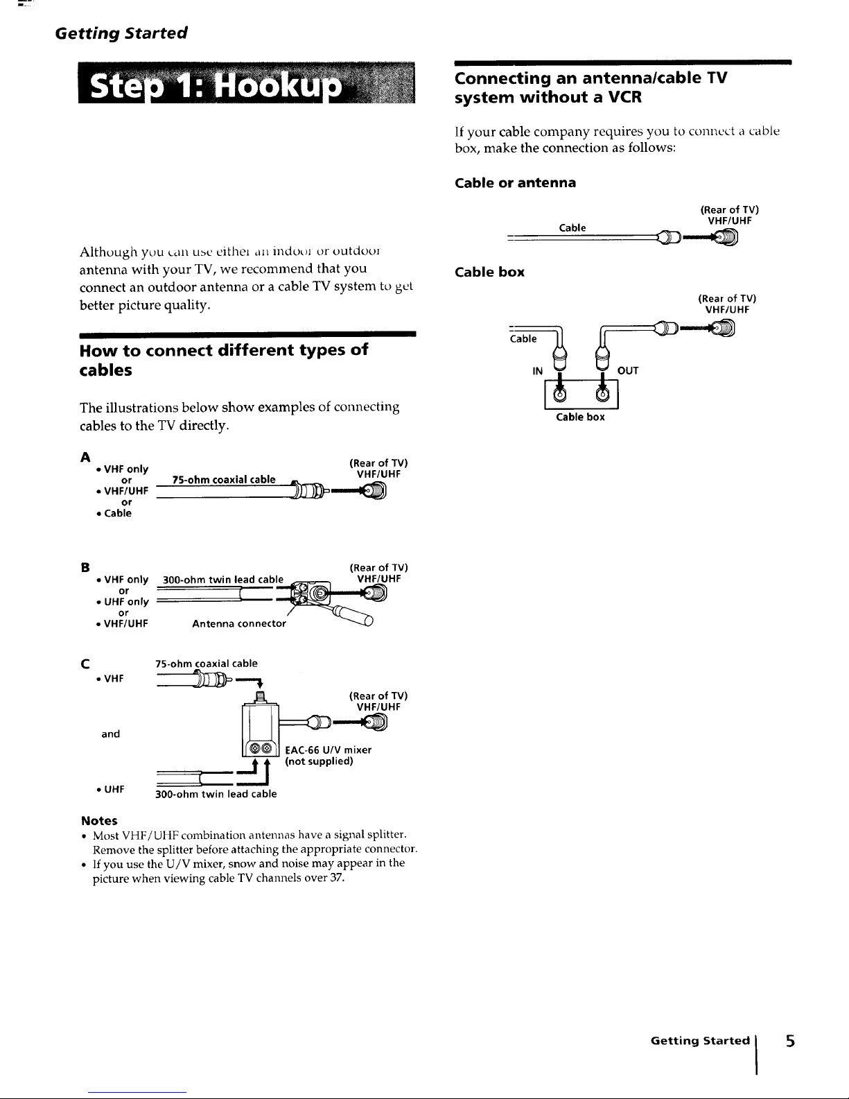
How to connect different types of
cables
The illustrations below show examples of connecting
cables to the TV directly.
A
• VHF only (Rear of TV)
or 75-ohm coaxial cable VHF/UHF
• VHFIUHF )_==_=_
or
• Cable
Connecting an antenna/cable TV
system without a VCR
If your cable company requires you to connect a cable
box, make the connection as follows:
Cable or antenna
Cable
(Rear of TV)
VHF/UHF
Cable box
Cable
(Rear of TV)
VHF/UHF
Cable box
B (Rear of TV)
• VHF only 300-ohm twin lead cable VHF/UHF
or
• UHF only !
or
• VHF/UHF Antenna connector
C
75-ohm coaxial cable
• VHF -__ ,--_
(Rear of TV)
and 1=__ _HF
EAC-66 U/V mixer
"J i (not supplied)
/
• UHF 300-ohm twin lead cable
Notes
• Most VHF/UHF combination antennas have a signal splitter.
Remove the splitter before attaching the appropriate connector.
• If you use the U/V mixer, snow and noise may appear in the
picture when viewing cable TV channels over 37.
Getting Started I
5

II |
Connecting an antenna/cable TV system with a VCR
To connect your VCR to the TV, first check the model
number of your TV and select the corresponding
connection. For details on connection, see the
instruction manual of your VCR.
Before making the connection, disconnect the AC
power cords of the equipment to be connected.
Without a cable box
After making these connections, you will be able to do
the following:
• View the playback of video tapes
• Record one TV program while viewing another
program
(Rear of TV)
Cable
]_OUT
Antenna cable
VCR
AUDtO VIDEO
LINE
OUT
VHF/UHF
]
t
VMC-810S/820S
(not supplied)
VHF/UHF
©
VIDEO IN
VIDEO-
L
(MO_OI)"
AUDIO
I
R--
AUDIOOUT
(VAR/FIX)
VIDEO (yellow)
AUDIO-L (white)
AUDIO-R (red)
Note
• To connect a nlol_aural VCR, connect the audio output of tile
VCR to AUDIO-L (mono) of VIDEO IN on the TV.
To an S video equipped VCR without a cable box
• KVo27V20/29V20M only
If your VCR has an S video output jack, make the
following connections.
6
Cable
Antenna cable
J O0T oo,ov,o o ,,
YC-15V/30V
(not supplied)
L
i
RK-74A
(not supplied)
Getting Started
(Rear of TV)
_ S VIDEO_
S VIDEO
AUDIO-R (red)
AUDIO-L (white)
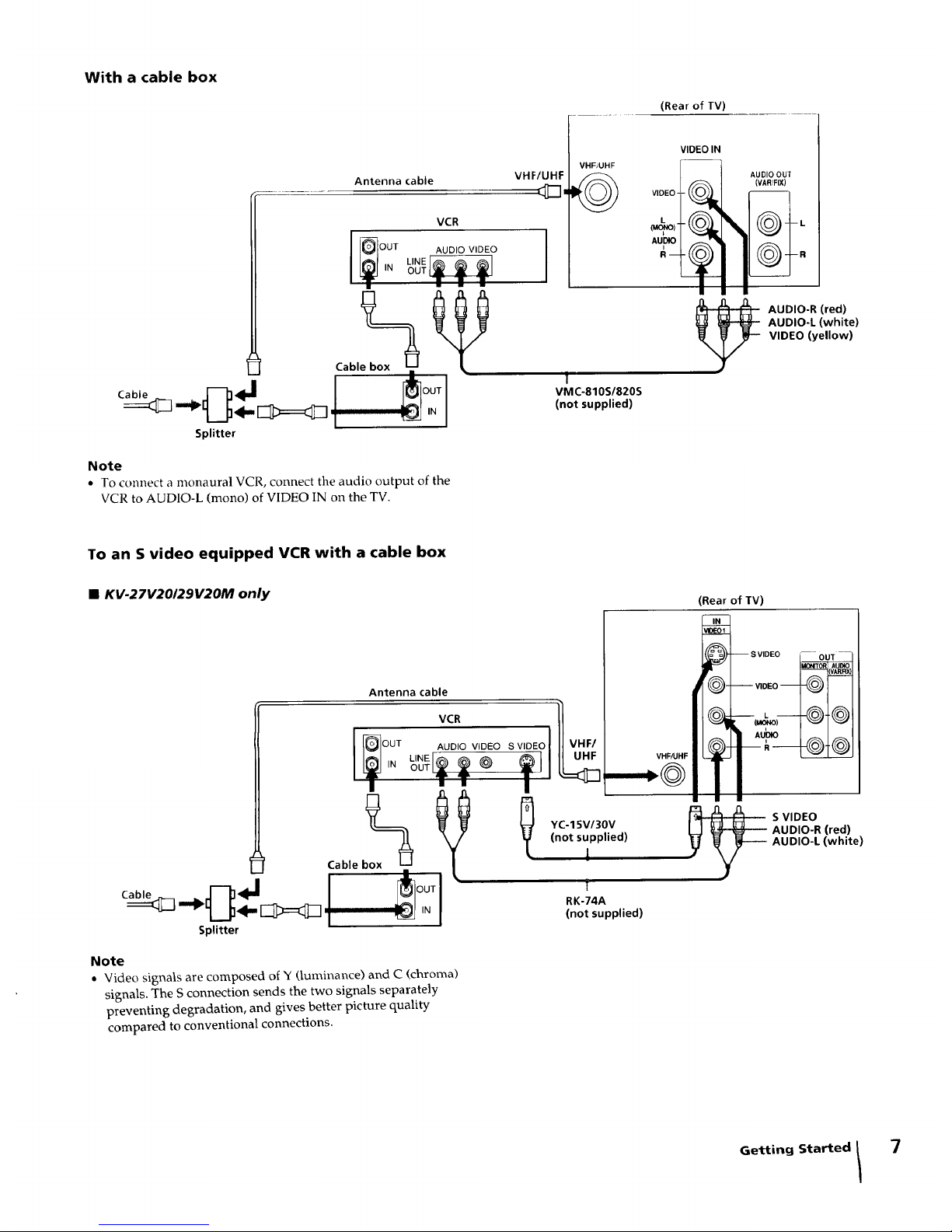
With a cable box
(Rear of TV)
Antenna cable
I VCR
,,
Splitter
Note
• To connect a monaural VCR, connect the audio output of the
VCR to AUDIO-L (mono) of VIDEO IN on the TV.
VHF/UHF
VHF/UHF
©
VIDEO IN
VIDEOL _
AUI:_I _"_
1
VMC-810S/820S
(not supplied)
AUDIO OUI
(VAR/FIX)
I il I
_ UDIO-R (red)
AUDIO-L (white)
VIDEO (yellow)
To an S video equipped VCR with a cable box
• KV-27V20/29V20M only
(Rear of TV)
Antenna cable
[ _OUT AVuCDIROVIDEO SVIDEOI I VHF,
Cable box_ t
VHF/UHF
.--.@
_ YC-15V/30V _ _
(notsupplied)
A
RK-74A
(notsupplied)
I
Splitter
_ S VIDEO_
__ -__
S VIDEO
AUDIO-R (red)
AUDIO-L (white)
Note
• Video signals are composed of Y (luminance) and C (chroma)
signals. The S connection sends the two signals separately
preventing degradation, and gives better picture quality
compared to conventional connections.
Getting Started /
7
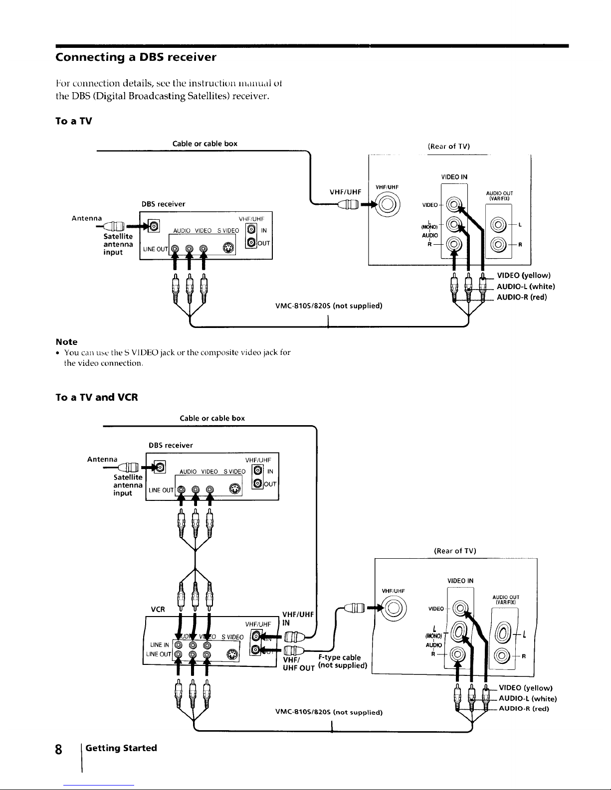
Connecting a DBS receiver
For connection details, see the instruction manual ot
the DBS (Digital Broadcasting Satellites) receiver.
To a TV
Antenna
Satellite
antenna
input
Cable or cable box
DBS receiver
AUDIO VIDEO
VHF/UHF I
SVIDEO ]_ IN I
I
VHF/UHF
(Rear of TV)
VHF/UHF
©
VMC-810S/820S (not supplied)
1
VIDEO IN
AUDIO
I ! !
Note
• You can u,su the S VIDEO jack or tile composite video jack for
tile video connection.
AUDIO OUT
(VAR,_FIX)
VIDEO (yellow)
AUDIO-L (white)
AUDIO-R (red)
To a TV and VCR
Cable or (able box
8
Antenna
.-<_,
Satellite
antenna
input
DBS receiver
VHF/UHF 1
AUDIO VIDEO SVIDEO I-_ IN I
l____l°UT[
VCR VHF/UHI
D V 0 S VIDEO
LINEIN @ @ @
/LINEOUTL__ _ J V.I:, F-type€able
J{JHI:'OUT (not supplied)
I II
I Getting Started
VHF/UHF
©
VMC-810S/820S (not supplied)
[
(Rear of TV)
VIDEO
L
AUDIO
VIDEO IN
AUDIO OUT
(VAR/FIX)
L
R
_ VIDEO (yellow)
AUDIO-L (white)
AUDIO-R (red)
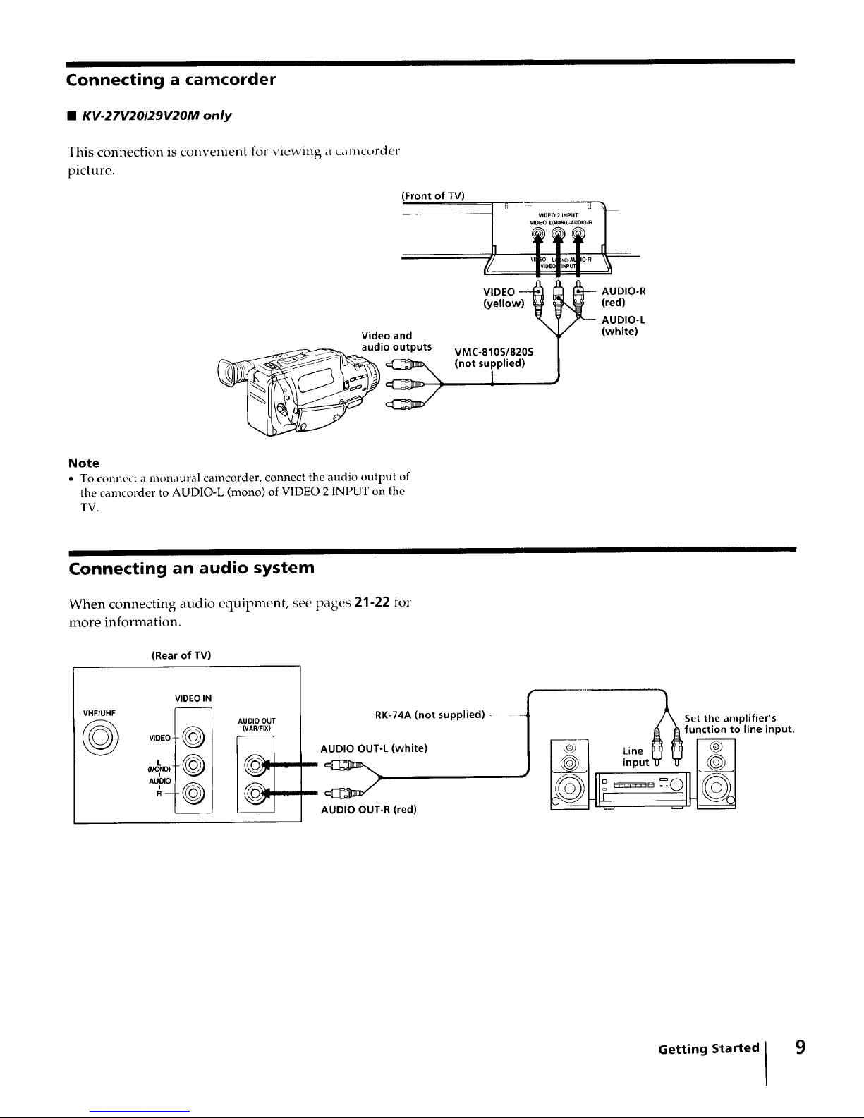
Connecting a camcorder
• KV-27V20129V20M only
This connection is convenient for viewing a camct_rder
picture.
(Front of JV)
Video and
audioeutput_
Note
• To connect a monaural camcorder, connect the audio output of
the camcorder to AUDIO-L (mono) of VIDEO 2 INPUT on the
TV.
VIDEO ---_
(yellow) _
VMC-810S/820S
(not supplied)
I
_ UDIO-R
(red)
AUDIO-L
(white)
Connecting an audio system
When connecting audio equipment, see pages 21-22 for
more information.
(Rear of TV)
VHF/UHF
©
VIDEO IN
(VAR[FIX)
VIDEO
L
RK-74A (not supplied) -
AUDIO OUT-L (white)
AUDIO OUT-R (red)
•_J /_ Se,,he0,,_p,ifier's
Afunction to line input.
_-I _,neHN
I@1 input_1__ I@1
I_111__o_o11_1
Getting Started 9
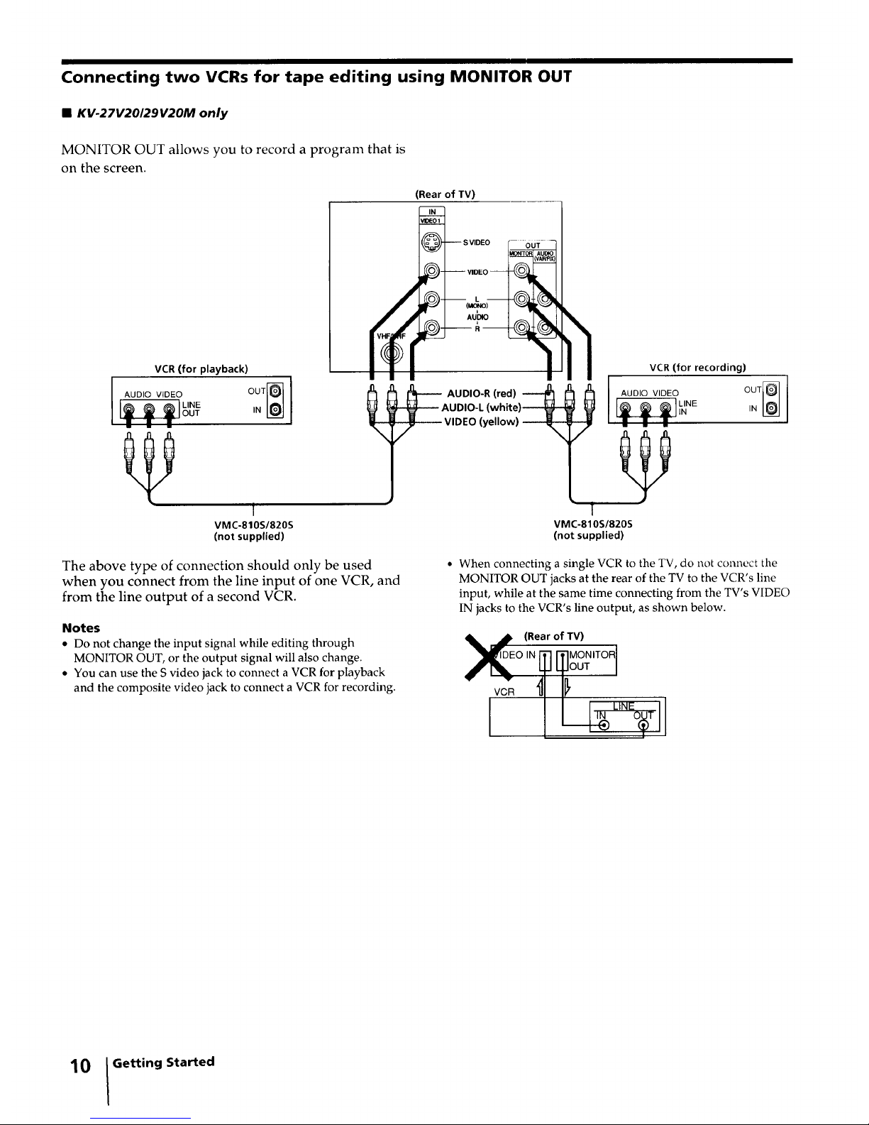
Connecting two VCRs for tape editing using MONITOR OUT
• KV-27V20/29V20M only
MONITOR OUT allows you to record a program that is
on the screen.
VCR (for playback)
L I,.o
f
VMC-810S/820S
(not supplied)
(Rear of TV)
'--- S VIDEO
AU DIO-R (red)
UI)IO-L(white)----_
VIDEO(yellow) ---_ ;
VCR (for recording)
I 0o,ov,o o I
VMC-810S/820S
(not supplied)
The above type of connection should only be used
when you connect from the line input of one VCR, and
from the line output of a second VCR.
Notes
• Do not change the input signal while editing through
MONITOR OUT, or the output signal will also change.
• You can use the S video jack to connect a VCR for playback
and the composite video jack to connect a VCR for recording.
• When connecting a single VCR to the TV, do not connect the
MONITOR OUT jacks at the rear of the TV to the VCR's line
input, while at the same time connecting from the TV's VIDEO
IN jacks to the VCR's line output, as shown below.
_VI_I (Rearof TV)
oi. ITIITIMONITORI
Lp qUOUT I
10 IGetting Started
 Loading...