

SONY KV-27S40, KV-27S45, KV-27S65, KV-29SL40, KV-29SL40A Service Manual
...
KV-27S40 / 27S45 / 27S65 / 29SL40 / 29SL40A / 29SL40C/
29SL45 / 29SL65 / 29SL65C/ 29XL40M / 29XL40P / 29XT11A
SELF-DIAGNOSTIC FUNCTION
SERVICE MANUAL
MODEL COMMANDER DEST. CHASSIS NO.
KV-27S40
KV-27S40
KV-27S45
KV-27S45
KV-27S65
KV-27S65
KV-29SL40
KV-29SL40A
KV-29SL40C
KV-29SL45
KV-29SL65
RM-Y165 US SCC-S01H-A
RM-Y165 CND SCC-S03E-A
RM-Y167 US SCC-S01J-A
RM-Y167 CND SCC-S03F-A
RM-Y167 US SCC-S01K-A
RM-Y167 CND SCC-S03G-A
RM-Y165 E SCC-S04X-A
RM-Y165 E SCC-S04S-A
RM-Y165 E SCC-S04U-A
RM-Y167 E SCC-S04Y-A
RM-Y167 E SCC-S06F-A
BA-4
CHASSIS
KV-29SL65C
KV-29XL40M
KV-29XL40P
KV-29XT11A
RM-Y167 E SCC-S04V-A
RM-Y165 MX SCC-S02D-A
RM-Y165 E SCC-S04R-A
RM-Y165 E SCC-S04T-A
KV-27S45
RM-Y167
TRINITRON® COLOR TV
— 1 —
KV-27S40 / 27S45 / 27S65 / 29SL40 / 29SL40A / 29SL40C/
29SL45 / 29SL65 / 29SL65C/ 29XL40M / 29XL40P / 29XT11A
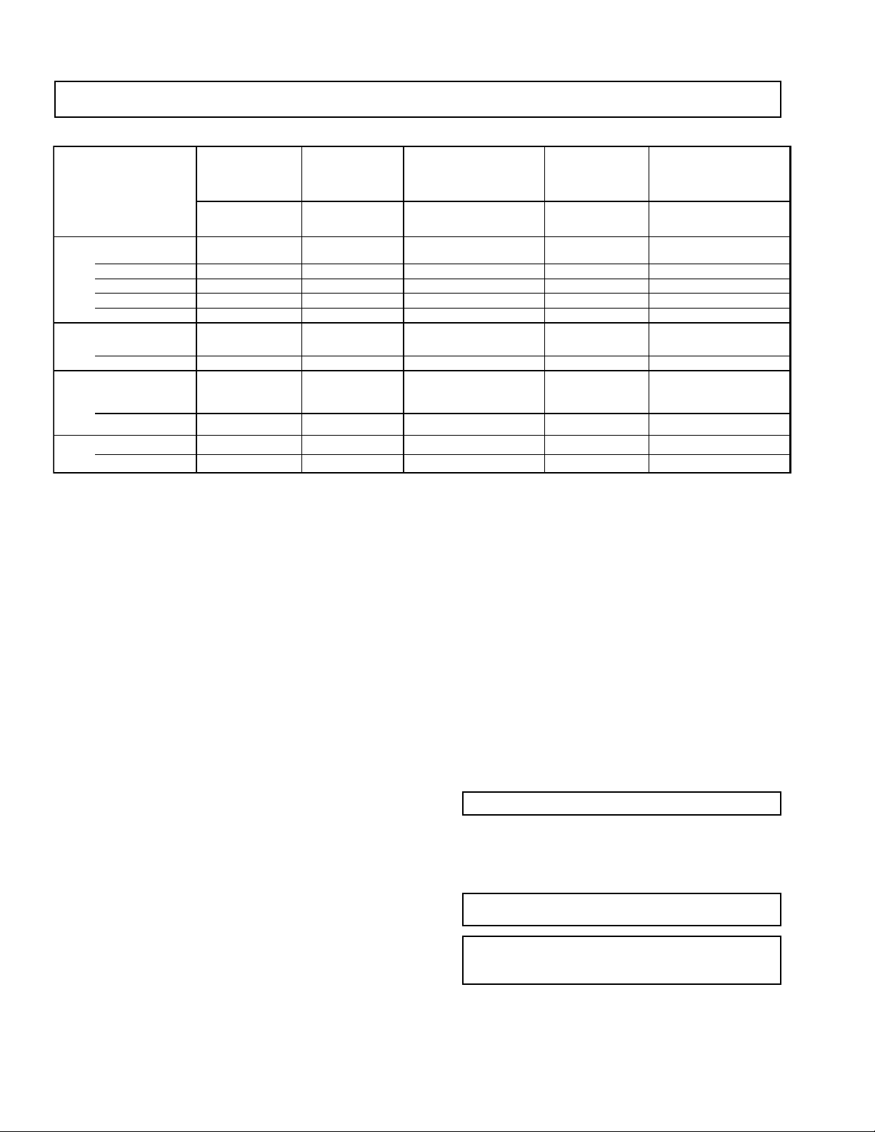
SPECIFICATIONS
KV-27S40
KV-29XL40M KV-27S45 KV-29SL40A
KV-29XL40P KV-27S65 KV-29SL40C
KV-29SL40 KV-29SL65 KV-29XT11A KV-29SL45 KV-29SL65C
Power Requirements 120V,60Hz 120V,60Hz 220V,50/60Hz 120V,60Hz 220V,50/60Hz
Number of inputs/outputs
Power Consumption(W)
Dimensions (W/H/D)
Mass (kg) 38 kg 38 kg 38 kg 38 kg 38 kg
Television system
American TV standard
PAL-M, PAL-L, NTSC (KV-29SL40A,29XT11A only)
1)
Video
2)
S Video
3)
Audio
Audio Out
Speaker Output (W) 5W x 2 5W x 2 5W x 2 10W x 2 10W x 2
In Use (Max) 140W 140W 140W 140W 140W
In Standby 2W 2W 3W 2W 3W
(mm) x 505.5mm x 505.5mm x 505.5mm x 505.5mm x 505.5mm
(in.) 26 x 23
(lbs) 84 lbs 84 lbs 84 lbs 84 lbs 84 lb s
4)
12 1 2 2
-1 - 1 1
12 1 2 2
11 1 1 1
660.4 x 598 660.4 x 598 660.4 x 598 660.4 x 598 660.4 x 598
1/2
x 20 in 26 x 23
1/2
x20 in 26 x 23
1/2
x 20 in 26 x 23
1)
1 Vp-p 75 ohms unbalanced, sync negative
2)
Y: 1 Vp-p 75 ohms unbalanced, sync negative
C: 0.286 Vp-p (Burst signal), 75 ohms
3)
500 mVrms (100% modulation), Impedance: 47 kilohms
4)
More than 408 mVrms at the maximum volume setting (variable)
1/2
x 20 in 26 x 23
1/2
x 20 in
Channel coverage
VHF:2-13/UHF:14-69/CATV:1-125
Visible screen size
27-inch picture measured
29-inch picture measured
Actual screen size
27-inch picture measured
29-inch picture measured
Antenna
75 ohm external terminal for VHF/UHF
Supplied Accessories
Remote commander (w/2 size AA (R6) batteries)
RM-Y165: (KV-27S40,29SL40/A/C,29XL40M,29XL40P,
29XT11A)
RM-Y167: (KV-27S45, 27S65, 29SL45, 29SL65,
29SL65C)
Optional Accessory
Connecting Cables:
VMC-810S/820S, MC-720M, YC-15V/30V, RK-74A
TV Stand SU-27A3
U/V Mixer EAC-66
(l ) SRS (SOUND RETRIEVAL SYSTEM)
The ( l ) SRS (SOUND RETRIEVAL SYSTEM) is manufactured by Sony Corporation under license from SRS
Labs, Inc. It is covered by U.S. Patent No. 4,748,669. Other
U.S. and foreign patents pending.
The word ‘SRS’ and the SRS symbol (l ) are registered
trademarks of SRS Labs, Inc.
BBE and BBE symbol are trademarks of BBE Sound,Inc.
and are licensed by BBE Sound, Inc. under USP
4638258.4482866,
Design and specifications are subject to change without notice.
— 2 —

TABLE OF CONTENTS
Section Title PageSection Title Page
KV-27S40 / 27S45 / 27S65 / 29SL40 / 29SL40A / 29SL40C/
29SL45 / 29SL65 / 29SL65C/ 29XL40M / 29XL40P / 29XT11A
Warnings and Caution ..................................................... 4
Self-Diagnostic Function ................................................ 4
Safety Check Out Instructions ........................................ 7
1. GENERAL
Connecting and Installing the TV ............................. 8
Basic Set Up .............................................................. 12
Using Y our TV.............................................................12
Using Y our Menus.......................................................15
Operating Video Equipment....................................... 19
Operating a Cable Box or DBS Receiver....................20
Troubleshooting.......................................................... 20
2. DISASSEMBLY
2-1. Rear Cover Removal .....................................................22
2-2. A Board Removal ..................................................... 22
2-3. Service Position ........................................................ 22
2-4. Picture Tube Removal ................................................... 23
3. SET-UP ADJUSTMENTS
3-1. Beam Landing.............................................................24
3-2. Convergence............................................................... 25
3-3. Focus........................................................................... 26
3-4. Screen (G2)................................................................. 26
3-5. Method of Setting the Service Adjustment Mode.......26
3-6. White Balance Adjustments........................................26
4. SAFETY RELATED ADJUSTMENTS......................... 27
5. CIRCUIT ADJUSTMENTS
5-1. Electrical Adjustment by Remote Commander...........29
5-2. A Board Adjustments.................................................. 32
6. DIAGRAMS
6-1. Block Diagrams.......................................................... 35
6-2. Circuit Boards Location..............................................38
6-3. Printed Wiring Boards and Schematic Diagrams .......38
• A Board...................................................................... 39
• P Board....................................................................... 47
• K Board ..................................................................... 49
• C Board...................................................................... 50
• E Board ...................................................................... 51
• HZ Board.................................................................... 52
6-4. Semiconductors...........................................................53
7. EXPLODED VlEWS
7-1. Chassis ..........................................................................54
(KV-27S40/27S45/29SL40/29SL45/29XL40M/29XL40P/
29XT11A/29SL40A/29SL40C)
7-2 . Chassis..........................................................................55
(KV-27S65/29SL65/29SL65C)
7- 3. Main Power Switch...................................................... 56
(KV-29SL40A/29XT11A)
8. ELECTRICAL PARTS LIST
• Table of Contents for Parts List...................................57
• A Board Common Parts List.......................................59
• A Board Variant Lists.................................................. 68
• C Board Parts List.......................................................79
• E Board Parts List.......................................................79
• K Board Parts List.......................................................80
• P Board Parts List....................................................... 81
• HZ Board Parts List.....................................................82
• Accessories and Packaging........................................ 82
— 3 —
KV-27S40 / 27S45 / 27S65 / 29SL40 / 29SL40A / 29SL40C/
g
g
)
y
(
)
)
(
(
y (
)
y
(
(
)
)
y
)
29SL45 / 29SL65 / 29SL65C/ 29XL40M / 29XL40P / 29XT11A
WARNINGS AND CAUTIONS
CAUTION!
SHORT CIRCUIT THE ANODE OF THE PICTURE TUBE AND
THE ANODE CAP TO THE METAL CHASSIS, CRT SHIELD,
OR CARBON PAINTED ON THE CRT, AFTER REMOVING
THE ANODE.
WARNING!!
AN ISOLATION TRANSFORMER SHOULD BE USED
DURING ANY SERVICE TO AVOID POSSIBLE SHOCK
HAZARD, BECAUSE OF LIVE CHASSIS.THE CHASSIS OF
THIS RECEIVER IS DIRECTLY CONNECTED TO THE AC
POWER LINE.
SAFETY-RELATED COMPONENT WARNING!!
COMPONENTS IDENTIFIED BY SHADING AND MARK
¡ ON THE SCHEMATIC DIAGRAMS, EXPLODED VIEWS
AND IN THE PARTS LIST ARE CRITICAL FOR SAFE
OPERATION. REPLACE THESE COMPONENTS WITH
SONY PARTS WHOSE PART NUMBERS APPEAR AS
SHOWN IN THIS MANUAL OR IN SUPPLEMENTS
PUBLISHED BY SONY. CIRCUIT ADJUSTMENTS THAT
ARE CRITICAL FOR SAFE OPERA TION ARE IDENTIFIED
IN THIS MANUAL. FOLLOW THESE PROCEDURES
WHENEVER CRITICAL COMPONENTS ARE REPLACED
OR IMPROPER OPERATION IS SUSPECTED.
SELF-DIAGNOSTIC FUNCTION
ATTENTION
APRES AVOIR DECONNECTE LE CAP DE L'ANODE, COURT-CIRCUITER
L'ANODE DU TUBE CATHODIQUE ET CELUI DE L'ANODE DU CAP AU
CHASSIS METALLIQUE DE L'APPAREIL, OU AU COUCHE DE CARBONE
PEINTE SUR LE TUBE CATHODIQUE OU AU BLINDAGE DU TUBE
CATHODIQUE.
ATTENTION!!
AFIN D'EVITER TOUT RESQUE D'ELECTROCUTION PROVENANT D'UN
CHÁSSIS SOUS TENSION, UN TRANSFORMATEUR D'ISOLEMENT DOIT
ETRE UTILISÉ LORS DE TOUT DÉPANNAGE. LE CHÁSSIS DE CE
RÉCEPTEUR EST DIRECTEMENT RACCORDÉ À L'ALIMENTATION
SECTEUR.
ATTENTION AUX COMPOSANTS RELATIFS A LA SECURITE!!
LES COMPOSANTS IDENTIFIES PAR UNE TRAME ET PAR UNE MARQUE
¡ SUR LES SCHEMAS DE PRINCIPE, LES VUES EXPLOSEES ET LES
LISTES DE PIECES SONT D'UNEIMPORTANCE CRITIQUE POUR LA
SECURITE DU FONCTIONNEMENT . NE LES REMPLACER QUE PAR DES
COMPOSANTS SONY DONT LE NUMERO DE PIECE EST INDIQUE DANS
LE PRESENT MANUEL OU DANS DES SUPPLEMENTS PUBLIES PAR
SONY . LES REGLAGES DE CIRCUIT DONT L'IMPORT ANCE EST CRITIQUE
POUR LA SECURITE DU FONCTIONNEMENT SONT IDENTIFIES DANS
LE PRESENT MANUEL. SUIVRE CES PROCEDURES LORS DE CHAQUE
REMPLACEMENT DE COMPOSANTS CRITIQUES, OU LORSQU'UN
MAUVAIS FONTIONNEMENT SUSPECTE.
The units in this manual contain a self-diagnostic function. If an error occurs, the STANDBY/TIMER lamp will automatically begin to
flash. The number of times the lamp flashes translates to a probable source of the problem. A definition of the STANDBY/TIMER lamp
flash indicators is listed in the instruction manual for the user's knowledge and reference. If an error symptom cannot be reproduced, the
remote commander can be used to review the failure occurrence data stored in memory to reveal past problems and how often these
problems occur.
1. DIAGNOSTIC TEST INDICATORS
When an error occurs, the ST ANDBY/TIMER lamp will flash a set number of times to indicate the possible cause of the problem. I f there
is more than one error, the lamp will identify the first of the problem areas.
Results for all of the following diagnostic items are displayed on screen. No error has occured if the the screen displays a "0" .
Diagnostic Item No. of times Self-diagnostic display/ Probable Cause Detected Symptoms
Description STANDBY/TIMER Dia
* Power does not turn on Does not li
* +B overcurrent
* Vertical deflection stopped 4 times 4:0 or 4:1 * +13V is not supplied.
* White balance failure 5 times 5:0 or 5:1 * Video OUT
not balanced
OCP
lamp flashes
ht * Power cord is not plugged in. * Power does not come on.
2 times 2:0 or 2:1 * H.OUT (Q502) is shorted. (A board
nostic result Location
* Fuse is burned out (F5050) (E Board
* IC1751 and Q1751 is shorted.
A board) * Has entered standby state after horizontal raster.
* IC 541 is fault
* IC301 is faulty. (A board
* G2 is improperl
A board
Q306 to 308) is faulty. (A board)* No raster is generated.
adjusted. (Note 2
* No power is suppled to the TV.
* AC power suppl
* Power does not come on.
C board)* Load on power line is shorted.
* Vertical deflection pulse is stopped.
* Power line is shorted or power suppl
* CRT cathode current detection reference pulse
output is small.
is faulty.
is stopped.
Note 1: If a +B overcurrent is detected, stoppage of the vertical deflection is detected simultaneously.
The symptom that is diagnosed first by the microcontroller is displayed on the screen.
Note 2: Refer to Screen (G2) Adjustment in Section 3-4 of this manual.
— 4 —

2. DISPLAY OF STANDBY/TIMER LIGHT FLASH COUNT
2 times
4 times
5 times
KV-27S40 / 27S45 / 27S65 / 29SL40 / 29SL40A / 29SL40C/
29SL45 / 29SL65 / 29SL65C/ 29XL40M / 29XL40P / 29XT11A
Lamp ON 0.3 sec.
Lamp OFF 0.3 sec.
Lamp OFF
STANDBY/SLEEP lamp
3 sec.
Diagnostic Item Flash Count*
+B overcurrent 2 times
Vertical deflection stopped 4 times
White balance failure 5 times
* One flash count is not used for self-diagnostic.
3. STOPPING THE STANDBY/TIMER FLASH
Turn off the power switch on the TV main unit or unplug the power cord from the outlet to stop the STANDBY/TIMER lamp from flashing.
4. SELF-DIAGNOSTIC SCREEN DISPLAY
For errors with symptoms such as "power sometimes shuts off" or "screen sometimes goes out" that cannot be confirmed, it is possible to bring up
past occurances of failure for confirmation on the screen:
[To Bring Up Screen Test]
In standby mode, press buttons on the remote commander sequentially in rapid succession as shown below:
Screen display
channel
5
Sound volume
–
Power ON
Note that this differs from entering the service mode (sound volume + ).
Self-Diagnostic screen display
SELF DIAGNOSTIC
2: 0 <-------------
Numeral "0" means that no fault has been detected.
3: N/A 0
4: 0
5: 1 <-------------
Numeral "1" means a fault has been detected one time only.
101: N/A 0
5. HANDLING OF SELF-DIAGNOSTIC SCREEN DISPLAY
Since the diagnostic results displayed on the screen are not automatically cleared, always check the self-diagnostic screen during repairs. When
you have completed the repairs, clear the result display to "0".
Unless the result display is cleared to "0", the self-diagnostic function will not be able to detect subsequent faults after completion of the repairs.
[Clearing the result display]
To clear the result display to "0", press buttons on the remote commander sequentially as shown below when the diagnostic screen is being
displayed.
ENTER
Channel
[Quitting Self-diagnostic screen]
To quit the entire self-diagnostic screen, turn off the power switch on the remote commander or the main unit.
8
— 5 —
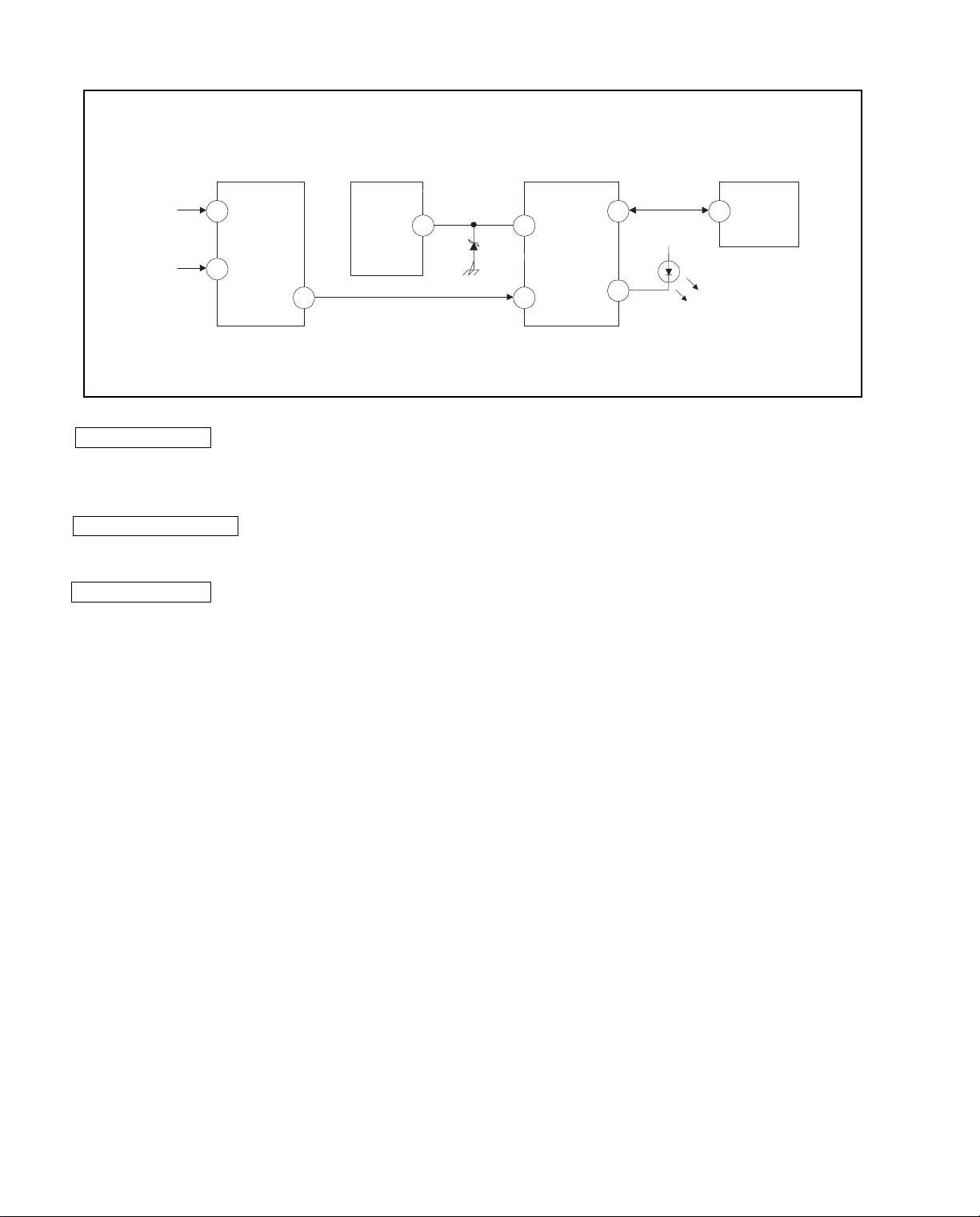
6. SELF-DIAGNOSTIC CIRCUIT
IC001
SYSTEM
17 I-PROT
37 SDAT
36 5
18
O-LED
MEMORY
B-DATIO-BDAT
FROM
CRT
FROM
IC521
PIN 7
IC301
Y/CHROMA JUNGLE
21
IK IN
18
HP/PROTECT
SDA
IC541
V.OUT
3
REF
35
+B overcurrent (OCP) Occurs when an overcurrent on the +B(115V) line is detected by pin 18 of IC301. If the
voltage to pin 18 of IC301 is less than 1V when V.SYNC is more than seven verticals in a
period, the unit will automatically turn off.
Vertical deflection stopped Occurs when an absence of the vertical deflection pulse is detected by pin 17 of IC001.
Power supply will shut down when waveform interval exceeds 2 seconds.
White balance failure If the RGB levels* do not balance within 2 seconds after the power is turned on, this error
will be detected by IC301. TV will stay on, but there will be no picture.
IC003
*(Refers to the RGB levels of the AKB detection Ref pulse that detects IK.)
— 6 —
SAFETY CHECK-OUT
KV-27S40 / 27S45 / 27S65 / 29SL40 / 29SL40A / 29SL40C/
29SL45 / 29SL65 / 29SL65C/ 29XL40M / 29XL40P / 29XT11A
After correcting the original service problem, perform the
following safety checks before releasing the set to the
customer:
1. Check the area of your repair for unsoldered or poorlysoldered connections. Check the entire board surface
for solder splashes and bridges.
2. Check the interboard wiring to ensure that no wires
are “pinched” or contact high-wattage resistors.
3. Check that all control knobs, shields, covers, ground
straps, and mounting hardware have been replaced.
Be absolutely certain that you have replaced all the
insulators.
4. Look for unauthorized replacement parts, particularly
transistors, that were installed during a previous
repair. Point them out to the customer and
recommend their replacement.
5. Look for parts which, though functioning, show
obvious signs of deterioration. Point them out to
the customer and recommend their replacement.
6. Check the line cords for cracks and abrasion.
Recommend the replacement of any such line cord
to the customer.
7. Check the B+ and HV to see if they are specified
values. Make sure your instruments are accurate;
be suspicious of your HV meter if sets always have
low HV.
8. Check the antenna terminals, metal trim, “metallized"
knobs, screws, and all other exposed metal parts for
AC Leakage. Check leakage as described below.
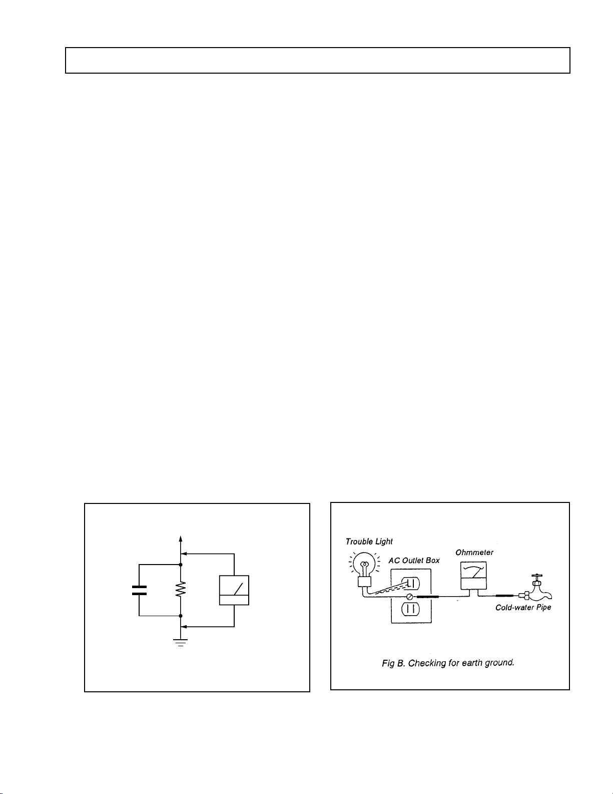
LEAKAGE TEST
The AC leakage from any exposed metal part to earth ground
and from all exposed metal parts to any exposed metal part having
a return to chassis, must not exceed 0.5 mA (500 microampere).
Leakage current can be measured by any one of three methods.
1. A commercial leakage tester, such as the Simpson 229 or
RCA WT-540A. Follow the manufacturers' instructions to
use these instructions.
2. A battery-operated AC milliammeter. The Data Precision
245 digital multimeter is suitable for this job.
3. Measuring the voltage drop across a resistor by means of
a VOM or battery-operated AC voltmeter. The "limit"
indication is 0.75 V, so analog meters must have an accurate
low voltage scale. The Simpson's 250 and Sanwa
SH-63Trd are examples of passive VOMs that are suitable.
Nearly all battery operated digital multimeters that have a
2V AC range are suitable. (See Fig. A)
HOW TO FIND A GOOD EARTH GROUND
A cold-water pipe is guaranteed earth ground; the cover-plate
retaining screw on most AC outlet boxes is also at earth ground.
If the retaining screw is to be used as your earth-ground, verify
that it is at ground by measuring the resistance between it and a
cold-water pipe with an ohmmeter. The reading should be zero
ohms. If a cold-water pipe is not accessible, connect a 60-l00 watts
trouble light (not a neon lamp) between the hot side of the receptacle and the retaining screw. Try both slots, if necessary, to
locate the hot side of the line, the lamp should light at normal
brilliance if the screw is at ground potential. (See Fig. B)
To Exposed Metal
Parts on Set
AC
1.5 k
0.15 µF
Fig. A. Using an AC voltmeter to check AC leakage.
Ω
Earth Ground
Voltmeter
(0.75 V)
— 7 —
KV-27S40 / 27S45 / 27S65 / 29SL40 / 29SL40A / 29SL40C/
29SL45 / 29SL65 / 29SL65C/ 29XL40M / 29XL40P / 29XT11A
SECTION 1
GENERAL
The instructions mentioned here are partial abstracts from the Operating Instruction Manual.
The page numbers shown reflect those of the Operating Instruction Manual.
Connecting and Installing the TV
Making Connections
Refer to the table below, it will direct you to the diagram suitable to the components you will be
connecting.
If you will be connecting See page
Cable or antenna only 5
Cable and antenna (KV-27S65, 27V65 only) 5
Cable box 6
Cable box and cable to view scrambled channels (KV-27S65, 27V65 only) 6
VCR and cable or antenna 7
VCR and cable box 7
Direct Broadcast Satellite Receiver (DBS) 8
VCR and Direct Broadcast Satellite Receiver (DBS) 9
Digital Versatile Disc receiver (DVD) 10
Audio system 10
Two VCRs for tape editing (KV-27V40, 27V45, 27V65 only) 11
Camcorder to view tapes 11
4
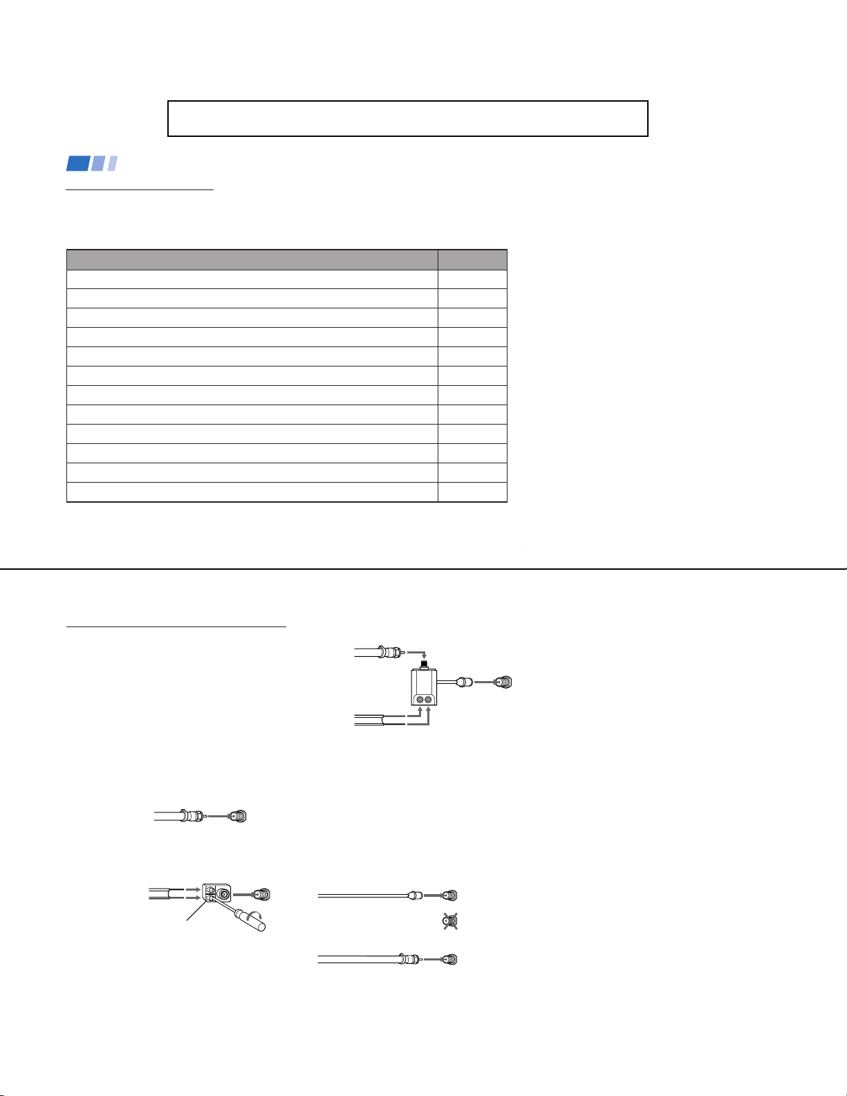
Cable or Antenna Connections
Connecting directly to cable or an
antenna
The connection you choose will depend on the
cable found in your home. Newer homes will
be equipped with standard coaxial cable
(see
A
); older homes will probably have
300-ohm twin lead cable (see
homes may contain both (see
A
• VHF only
• VHF/UHF
• Cable
B
• VHF only
• UHF only
• VHF/UHF
or
or
or
or
75-ohm
coaxial cable
300-ohm twin
lead cable
Antenna connector
B
); still other
C
).
(Rear of TV)
VHF/UHF
(Rear of TV)
VHF/UHF
C
75-ohm coaxial cable
• VHF
and
• UHF
300-ohm twin lead cable
(Rear of TV)
VHF/UHF
EAC-66 U/V mixer
(not supplied)
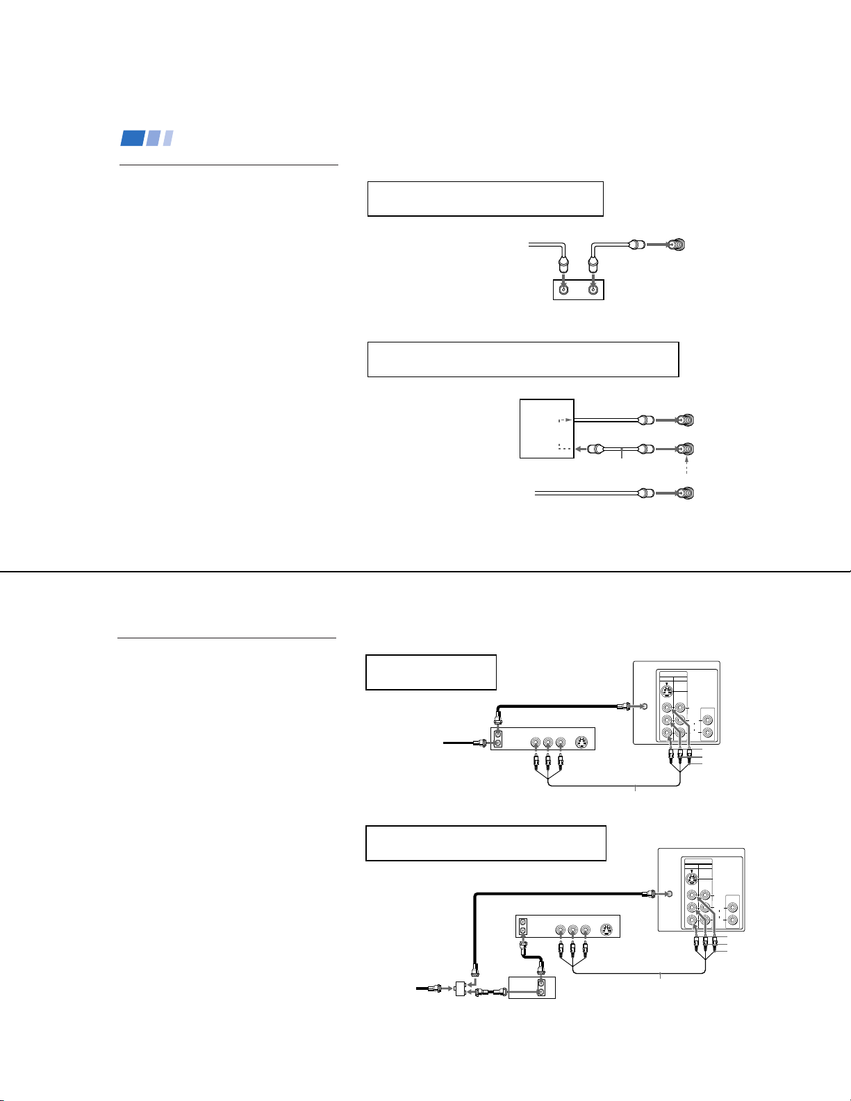
Cable and antenna
• KV-27S65, 27V65 only
If your cable provider does not feature local
channels, you may find this set up convenient.
Select Cable or ANT mode by pressing ANT
on the remote control. You will be able to
alternate between the two input sources.
(Rear of TV)
CATV cable
(No connection "TO
CONVERTER" in this case)
Antenna cable
AUX
TO CONVERTER
Note
• In order to receive channels with an
antenna, you will need to turn your CABLE
to OFF (see page 23) and perform the
AUTO PROGRAM function.
— 8 —
VHF/UHF
5
Connecting and Installing the TV (continued)
KV-27S40 / 27S45 / 27S65 / 29SL40 / 29SL40A / 29SL40C/
29SL45 / 29SL65 / 29SL65C/ 29XL40M / 29XL40P / 29XT11A
Cable Box Connections
Some pay cable TV systems use scrambled or
encoded signals that require a cable box* to
view all channels.
Cable box
1
Connect the coaxial connector from your
cable or antenna to the IN on your cable
box.
2
Using a coaxial cable, connect OUT on
your cable box to VHF/UHF on your TV.
Cable box and cable
• KV-27S65, 27V65 only
For this set up, you can switch between
scrambled channels (through your cable box),
and normal (CATV) channels by pressing
ANT on your remote control.
Notes
• Your Sony remote control can be
programmed to operate your cable box.
(see page 28)
• When using PIP, you cannot view the
window picture with the AUX input.
6
If you will be controlling all channel selection
through your cable box, you should consider using
the CHANNEL FIX feature discussed on page 23.
(Rear of TV)
Cable
OUTIN
*Cable box
If you are connecting a cable box through the AUX input and would
like to switch between the AUX and normal (CATV) input you should
consider using the CHANNEL FIX feature discussed on page 23.
*Cable box
scrambled
channels
75-ohm coaxial
cable (not supplied)
CATV cable
(unscrambled channels)
TO CONVERTER
VHF/UHF
(Rear of TV)
AUX
(signal)
VHF/UHF
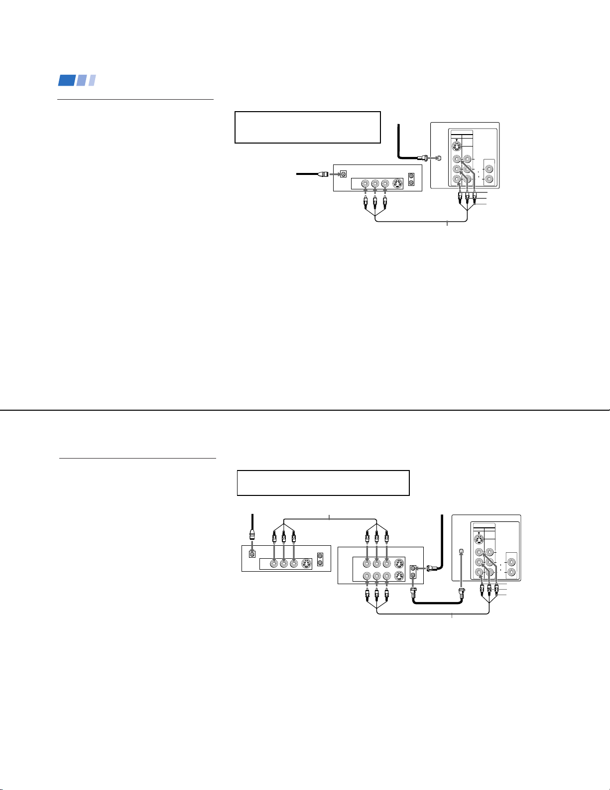
VCR Connections
Connecting an antenna/cable TV
system with a VCR
1
Attach the coaxial connector from your cable
or antenna to IN on your VCR.
2
Using A/V connectors, connect AUDIO and
VIDEO OUT on your VCR to AUDIO and
VIDEO IN on your TV (Yellow-VIDEO,
White-AUDIO Left, Red-AUDIO Right).*
3
Using a coaxial connector, connect OUT on
your VCR to VHF/UHF on your TV.
* If you are connecting a monaural VCR, connect only the
single white audio output to the left input on your TV.
Connecting a VCR and TV with a
cable box
You will need a splitter (not supplied) for the
following connection.
1
Connect the single (input) jack of the splitter
to your incoming cable connection. Connect
the other two (output) jacks (using coaxial
cable) to IN on your cable box and VHF/UHF
on your TV.
2
Using a coaxial connector, connect OUT on
your cable box to IN on your VCR.
3
Using A/V connectors, connect AUDIO and
VIDEO OUT on your VCR to AUDIO and
VIDEO IN on your TV (Yellow-VIDEO,
White-AUDIO Left, Red-AUDIO Right).
Disconnect all power sources before making any connections.
VCR must be connected and
turned on to operate PIP
(KV-27S45, 27V45 only).
Coaxial cable
3
Cable
1
OUT
IN
VCR
AUDIO R AUDIO L VIDEO
LINE
OUT
S VIDEO
2
VMC-810S/820S (not supplied)
For optimum picture quality, use S VIDEO instead of
the yellow A/V cable. S Video does not provide sound,
your audio connectors must still be connected.
Coaxial cable
VCR
OUT
AUDIO R AUDIO L VIDEO
LINE
IN
OUT
2
1
Cable
(not supplied)
Splitter
Cable box
OUT
IN
(Rear of TV)
VIDEO
IN
12
VHF/UHF
S VIDEO
AUDIO OUT
(
VAR/FIX
VIDEO
L
(
)
MONO
AUDIO
R
AUDIO-R (red)
AUDIO-L (white)
VIDEO (yellow)
(Rear of TV)
VIDEO
IN
12
VHF/UHF
S VIDEO
3
VMC-810S/820S (not supplied)
)
S VIDEO
AUDIO OUT
(
)
VAR/FIX
VIDEO
L
(
)
MONO
AUDIO
R
AUDIO-R (red)
AUDIO-L (white)
VIDEO (yellow)
7
— 9 —
KV-27S40 / 27S45 / 27S65 / 29SL40 / 29SL40A / 29SL40C/
29SL45 / 29SL65 / 29SL65C/ 29XL40M / 29XL40P / 29XT11A
Connecting and Installing the TV (continued)
DBS Connections
Connecting a DBS (Direct
Broadcast Satellite) receiver
1
Connect the cable from your satellite
antenna to your DBS receiver.
2
Attach the coaxial connector from your
cable or antenna to VHF/UHF on your
TV.
3
Using A/V connectors, connect AUDIO
and VIDEO OUT on your DBS receiver to
AUDIO and VIDEO IN on your TV.
Disconnect all power sources before making any connections.
For optimum picture quality, use S VIDEO
instead of the yellow A/V cable. S Video does
not provide sound, your audio connectors
must still be connected.
DBS receiver
1
Satellite
antenna
cable
SATELLITE IN
LINE OUT
AUDIO R AUDIO L VIDEO
3
(Rear of TV)
VHF/UHF
VIDEO
12
2
S VIDEO
VHF/UHF
IN
OUT
VMC-810S/820S (not supplied)
IN
S VIDEO
AUDIO OUT
VIDEO
L
(
)
MONO
AUDIO
R
(
)
VAR/FIX
AUDIO-R (red)
AUDIO-L (white)
VIDEO (yellow)
8
DBS Connections (continued)
Connecting a DBS (Direct Broadcast
Satellite) receiver and a VCR
1
Connect the cable from your satellite
antenna to your DBS receiver.
2
Attach the coaxial connector from your
cable or antenna to VHF/UHF IN on your
VCR.
3
Using a coaxial connector, connect
VHF/UHF OUT on your VCR to
VHF/UHF on your TV.
4
Using A/V connectors, connect AUDIO
and VIDEO OUT on your DBS receiver to
AUDIO and VIDEO IN on your VCR.
5
Using A/V connectors, connect AUDIO
and VIDEO OUT on your VCR to AUDIO
and VIDEO IN on your TV.
Note
• To view from the DBS or VCR, select the
video input to which your DBS receiver or
VCR is connected by pressing TV/VIDEO
on the remote control.
Disconnect all power sources before making any connections.
For optimum picture quality, use S VIDEO instead of
the yellow A/V cable. S Video does not provide sound,
your audio connectors must still be connected.
VMC-810S/820S (not supplied)
SATELLITE IN
LINE OUT
4
AUDIO R AUDIO L VIDEO
S VIDEO
VHF/UHF
VCR
IN
OUT
AUDIO R AUDIO L VIDEO
LINE IN
LINE OUT
1
DBS receiver
5
(Rear of TV)
VHF/UHF
S VIDEO
VHF/UHF
2
IN
OUT
3
VMC-810S/820S (not supplied)
VIDEO
IN
12
VIDEO
S VIDEO
AUDIO OUT
(
)
VAR/FIX
L
(
)
MONO
AUDIO
R
AUDIO-R (red)
AUDIO-L (white)
VIDEO (yellow)
— 10 —
9
10
The following connections are for accessories
that will enhance your viewing options.
Connecting a DVD Player
Additional Connections
VMC-810S/820S (not supplied)
AV outputs
1
(Rear of DVD player)
AUDIO-R (red)
AUDIO-L (white)
VIDEO (yellow)
Connecting and Installing the TV (continued)
VHF/UHF
Line
input
AUDIO-R (red)
AUDIO-L (white)
RK-74A
(not supplied)
1
2
Disconnect all power sources before making any connections.
For optimum picture quality, use S VIDEO
instead of the yellow A/V cable. S Video
does not provide sound, your audio
connectors must still be connected.
Note
• For the best picture quality, connect the
DVD player directly to the TV.
(Rear of TV)
(Rear of TV)
1
Using A/V connectors, connect LINE OUT
on your DVD to VIDEO IN on your TV
(Red-AUDIO Right, White-AUDIO Left,
Yellow-VIDEO).
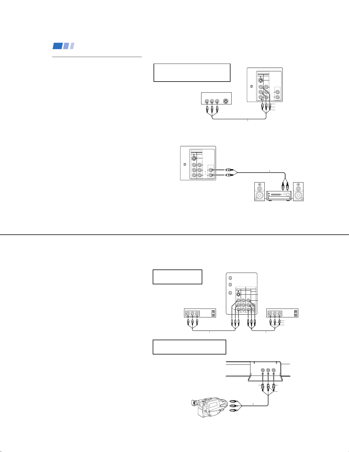
Connecting an audio system
For enhanced sound, connect your audio
system to your TV.
1
Using AUDIO connectors, connect AUDIO
OUT on your TV to one of the unused line
inputs (e.g. TV, AUX, TAPE 2) on your
stereo (White-AUDIO Left, Red-AUDIO
Right).
2
Set your stereo to the chosen line input
(e.g. TV, AUX, TAPE 2). Refer to page 20
of this manual for additional audio setup
instructions.
VIDEO
IN
12
LINE OUT
AUDIO R AUDIO L VIDEO
S VIDEO
AUDIO OUT
(
)
VAR/FIX
VIDEO
L
(
)
MONO
AUDIO
R
S VIDEO
KV-27S40 / 27S45 / 27S65 / 29SL40 / 29SL40A / 29SL40C/
29SL45 / 29SL65 / 29SL65C/ 29XL40M / 29XL40P / 29XT11A
VIDEO
IN
12
VHF/UHF
S VIDEO
VIDEO
AUDIO
L
(
MONO
R
AUDIO OUT
(
VAR/FIX
)
)
Connecting two VCRs for tape
editing using MONITOR OUT
• KV-27V40, 27V45, 27V65 only
MONITOR OUT gives you the ability to use a
second VCR to record a program being played
by the primary VCR or to perform tape
editing and dubbing.
1
Connect the VCR intended for playback
using the setup instructions on page 7 of
this manual.
2
Using A/V connectors, connect AUDIO
and VIDEO IN on your VCR intended for
recording to MONITOR AUDIO and
VIDEO OUT on your TV.
Connecting a camcorder
This connection is convenient for viewing a
picture directly from your camcorder.
Using A/V connectors, connect AUDIO and
VIDEO OUT on your camcorder to AUDIO
and VIDEO IN on your TV (Yellow-VIDEO,
White-AUDIO Left, Red-AUDIO Right).
Connection can also be made directly to your
A/V input located on the rear of your TV.
Note
If you are connecting a monaural camcorder,
•
connect only the single white audio output
to the left input on your TV.
You cannot change video
inputs while editing using
MONITOR OUT.
If you have an S Video equipped
camcorder, you can use an S Video
connection for optimum picture quality.
1
Disconnect all power sources before making any connections.
(Rear of KV-27V65)
AUX
TO
CONVERTER
IN
OUT
VIDEO 3 MONITOR
VIDEO 1
VHF/UHF
L
(
)
VCR (for playback)
AUDIO R AUDIO L VIDEO AUDIO R AUDIO L VIDEO
OUT
LINE
IN
OUT
MONO
AUDIO
R
AUDIO
(VAR/FIX)
S VIDEO
VIDEO
VCR (for recording)
2
VMC-810S/820S (not supplied)
AV output
VMC-810S/820S (not supplied)
(Front of KV-27V40, 27V45, 27V65 only)
VIDEO 2 INPUT
(
)
L
-
AUDIO
MONO
VIDEO
(
)
L
-
AUDIO
MONO
VIDEO 2 INPUT
VIDEO (yellow)
VMC-810S/820S
(not supplied)
HRD
OUT
LINE
IN
IN
VIDEO (yellow)
AUDIO-L (white)
AUDIO-R (red)
-RVIDEO
-
R
AUDIO-R (red)
AUDIO-L (white)
11
— 11 —
KV-27S40 / 27S45 / 27S65 / 29SL40 / 29SL40A / 29SL40C/
0
29SL45 / 29SL65 / 29SL65C/ 29XL40M / 29XL40P / 29XT11A
Basic Set up
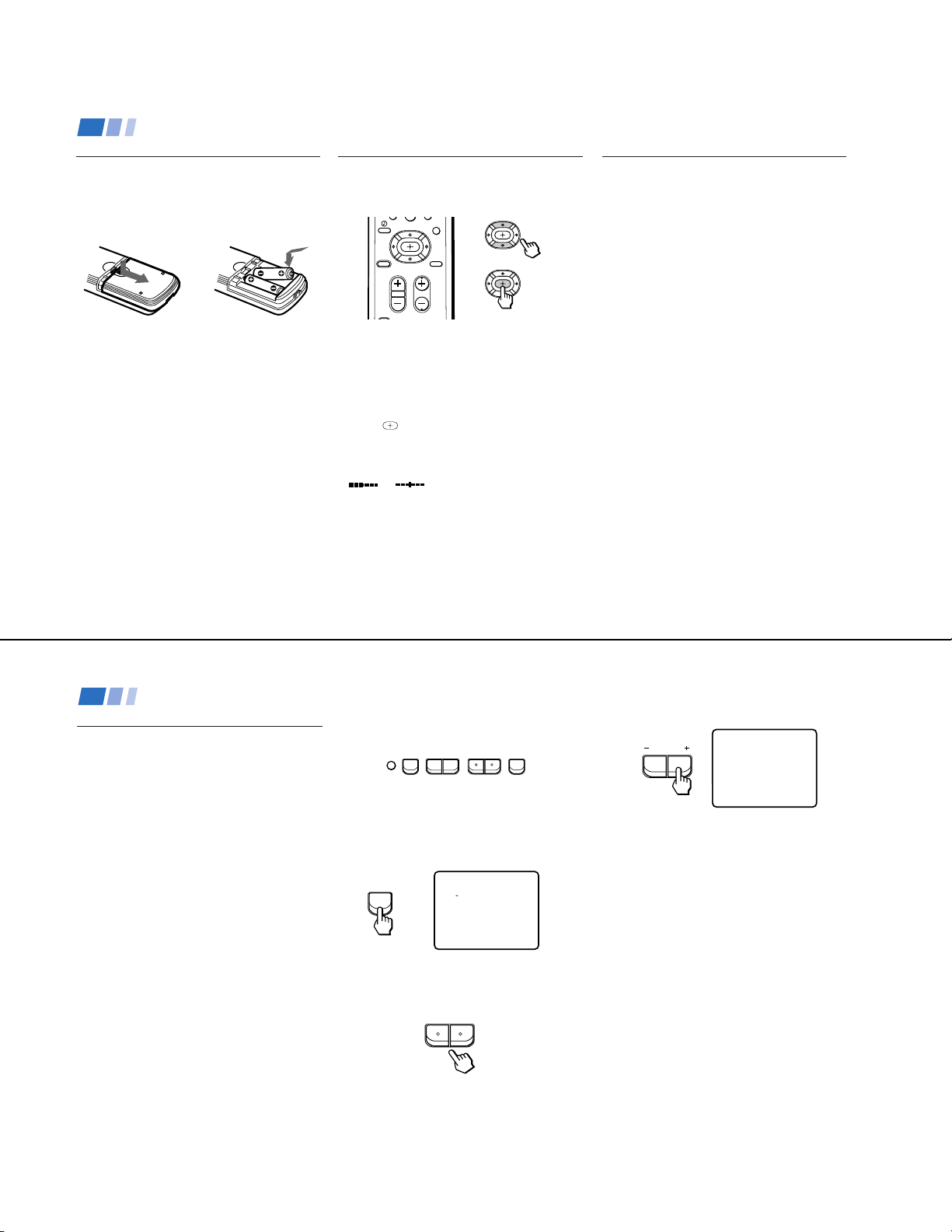
Inserting batteries
Insert two size AA (R6) batteries (supplied) by
matching the + and – on the batteries to the
diagram inside the battery compartment.
Notes
• Remove the batteries to avoid damage
from possible battery leakage whenever
you anticipate that the remote control will
not be used for an extended period.
• Handle the remote control with care.
Avoid dropping it, getting it wet, or
placing it in direct sunlight, near a heater,
or where the humidity is high.
• Your remote control can be programmed to
operate most video equipment. (see page 26)
12
Using the remote control,
Move & Select buttons
TV DBS
RESET MENU
CODE SET
The supplied remote control has "arrow"
buttons (V, v, B, b) which allow for
movement of the on-screen selector in four
directions. Pressing on the outer buttons will
cause the selector to move in the
corresponding direction. Pressing the center
button (
Adjustments bars
When menu items present an adjustment bar
(
or ), use the arrow buttons to
change the setting.
MTS
GUIDE
CHVOL
) will select the item.
Move
Select
On-Screen Help/Instructions
Several menu windows will provide prompts
and instructions to assist you in navigating
through the different functions. When
presented, use these to supplement the instructions
in this manual.
Note
• To reset your TV to factory settings, turn
the TV on. Then, while pressing the RESET
button, press the POWER key on your TV.
The TV will turn itself off, then back on.
(except KV-20V80).
Using your New TV
Setting up the TV automatically
The Easy Setup Guide allows you to set the
on-screen language and set all receivable
channels. The Easy Setup Guide screen
appears every time you turn on the TV until
you perform AUTO PROGRAM.
The Easy Setup Guide feature does not apply for
installations that use a cable box for all channel
selection.
To set up the TV manually, refer to “Using the
SET UP menu” on page 23.
Tips
z
• Perform this function during the day, with the antenna
and/or cable properly connected, to ensure that all available
channels will be broadcasting and receivable.
• After using the Easy Setup Guide you will still have the
option of adjusting any of the system settings, like skipping
channels, through the SET UP menu (page 24).
The TV must be set to the TV input to execute AUTO
•
PROGRAM. Press ANT until a channel number appears.
• If your cable or antenna is connected to AUX, then
press ANT until AUX appears next to the channel
number. (KV-27S65, 27V65 only)
Using the buttons on the front of the TV:
– CHANNEL +– VOLUME +
SET UP
TV/VIDEO
POWER
For KV-27V65, the control buttons are located
on the top of the TV.
1
Press POWER to turn on the TV.
The Easy Setup Guide screen appears.
POWER
2
(except Canadian models)
ENGLISH: [CH+]
ESPANOL: [CH-]
AUTO SET UP: [VOL+]
DEMO: [VOL-]
First please connect
cable/antenna.
Press [SETUP]to exit
Press CH + to select English screens or
CH – to select Spanish screens.
– CHANNEL +
3
Press VOL + to continue or VOL – for a
DEMO of functions and menus.
VOLUME
AUTO PROGRAM
AUTO PROGRAM appears and the TV
starts scanning and presetting channels
automatically. When all the receivable
channels are stored, the lowest numbered
channel is displayed. If the TV receives
cable TV channels, CABLE is set ON
automatically.
To perform AUTO SET UP again
• Press SET UP on the TV.
•
Press CH + or CH – to select a language.
• Press VOL + to restore factory settings
(CONTINUE TO AUTO PROGRAM? will
appear on the screen). Press CH + to
continue or CH – to exit.
• Press SET UP to exit.
Note
• When you perform AUTO PROGRAM,
your CHANNEL FIX, CHANNEL BLOCK
and ON/OFF TIMER settings will be
erased.
13
— 12 —
Using your New TV (continued)
KV-27S40 / 27S45 / 27S65 / 29SL40 / 29SL40A / 29SL40C/
29SL45 / 29SL65 / 29SL65C/ 29XL40M / 29XL40P / 29XT11A
Watching the TV
All of the TV features can be accessed via the
remote control. The following chart will
explain the function of the buttons found on
your remote control.
Using the White Labeled Buttons for TV Operations.
14
VTR/DVD
FUNCTION
POWER
TV
-
0 9
CH
JUMP
MUTING
Activate the remote control for use with the following components: TV, DBS/CABLE,
TVDBS/CABLE
VTR/DVD. Press when you want to control connected components with your remote
control. (see pages 26-28 for instructions on programming your remote control)
Turns the TV on and off. If VIDEO appears on the screen, press TV/VIDEO or
ANT until a channel number appears.
Use for direct channel selection. Press 0-9 to select a channel, the channel will
change after 2 seconds, or you can press ENTER for immediate selection.
Press to scan through the channels.
Keeping the CH + or – pressed allows you to rapidly scan to the desired channel.
Press to alternate or
jump
between the last two channels selected with the 0-9 keys.
Press to mute the sound (MUTING will appear on the screen). Press again or
press VOL + to restore sound.
REFER TO THE
ILLUSTRATION OF THE
REMOTE CONTROL ON THE
INSIDE FRONT COVER OF
THIS MANUAL AS YOU
REVIEW THIS CHART
back and forth between two channels. You can jump
FREEZE
SLEEP
DISPLAY
TV/VIDEO
ANT
(AUX input)
TV/VTR
+
MTS
GUIDE
Using the White Labeled Buttons for TV Operations.
Press to freeze the window picture while in PIP mode. If you are not in PIP mode,
pressing FREEZE will cause the main picture to freeze into a window picture.
Great for copying down phone numbers, addresses, recipes, etc.
Press repeatedly until the TV displays the approximate time in minutes (30, 60, or
90) that you want the TV to remain on before shutting off automatically.
Cancel by pressing until SLEEP OFF appears.
Press repeatedly to step through available displays:
Status
Channel number, current time, channel caption (if set) and Multi-Channel TV
Sound (MTS) are displayed.
The MTS mode indication disappears after three seconds.
CAPTION VISION
CAPTION VISION will be displayed on the screen if the broadcaster offers this
service. (see right)
To cancel the display, press DISPLAY repeatedly until DISPLAY OFF appears.
DISPLAY OFF disappears after three seconds.
Press repeatedly to step through available video inputs:
TV and VIDEO 1 (KV-27S40 only)
TV, VIDEO 1 and VIDEO 2 (KV-20V80, 27S45, 27S65, 27V40 only)
TV, VIDEO 1, VIDEO 2 and VIDEO 3 (KV-27V45, 27V65 only)
Press to change the VHF/UHF input to the AUX input (KV-27S65, 27V65 only).
For detailed connection information, see “Cable and antenna” or "Cable box and
cable” on pages 5-6.
Press when you are finished using a VCR and you want to switch to the TV input.
Your VCR power will remain on.
Press this button to cycle through the Multi-channel TV Sound (MTS) options.
(see page 21).
GUIDE is a feature of DBS, refer to your DBS operation instructions.
CAPTION VISION
(Closed Caption)
SET UP
CHANNEL SET UPŁ
FAVORITE CHANNELŁ
CHANNEL BLOCKŁ
VIDEO LABELŁ
CAPTION VISION:CC1
MENU
Move Select Exit
Some programs are broadcast with CAPTION
VISION.
CC1, 2, 3 or 4
Shows you a printed version of the dialog or
sound effects of a program. (The mode should
be set to CC1 for most programs)
TEXT1, 2, 3 or 4
Shows you network/station information
presented using either half or the whole screen.
It is not usually related to the program.
XDS (Extended Data Service)
Shows a network name, program name,
program length, and time of the show if the
broadcaster offers this service.
Note
• Poor reception of TV programs can cause
errors in CAPTION VISION and XDS.
Captions may appear with a white box or
other errors instead of intended text.
MENU
15
— 13 —
KV-27S40 / 27S45 / 27S65 / 29SL40 / 29SL40A / 29SL40C/
29SL45 / 29SL65 / 29SL65C/ 29XL40M / 29XL40P / 29XT11A
Using your New TV (continued)
Watching two programs at
one time - PIP
The Picture-in-Picture (PIP) feature allows you
to view two channels simultaneously, one in
the full size “main” picture and one in a smaller
“window” picture. This means that two
separate tuners must be available to provide
the two signals.
Certain models (KV-27S45, 27V45 only) are
equipped with a single tuner. This simply means
that a VCR must be connected and turned on for
PIP to operate.
Tip
z
To ensure a correct single tuner PIP connection
(KV-27S45, 27V45 only), make sure the following list
is complete before using PIP:
• A cable or antenna is connected to the VCR
• The VCR is connected to your TV
• The VCR is turned on
(for detailed connection information, see pages 5-7)
Note
• You must press TV (FUNCTION) before you
can control PIP with the yellow labeled buttons.
16
REFER TO THE ILLUSTRATION OF
THE REMOTE CONTROL ON THE
INSIDE FRONT COVER OF THIS
MANUAL AS YOU REVIEW THIS
CHART
Use the Yellow Labeled Buttons for PIP Operations.
PIP
TV/VIDEO
AUDIO
Press once to display the window picture (1/9 size).
Press again to reduce the size of the window picture (1/16 size).
Press a third time to remove the window picture.
Press repeatedly to step through available video inputs:
TV, VIDEO 1, VIDEO 2, and VIDEO 3 (KV-27S45, 27S65, 27V45,
27V65 only)
If you have a single tuner, your PIP input source is the VCR.
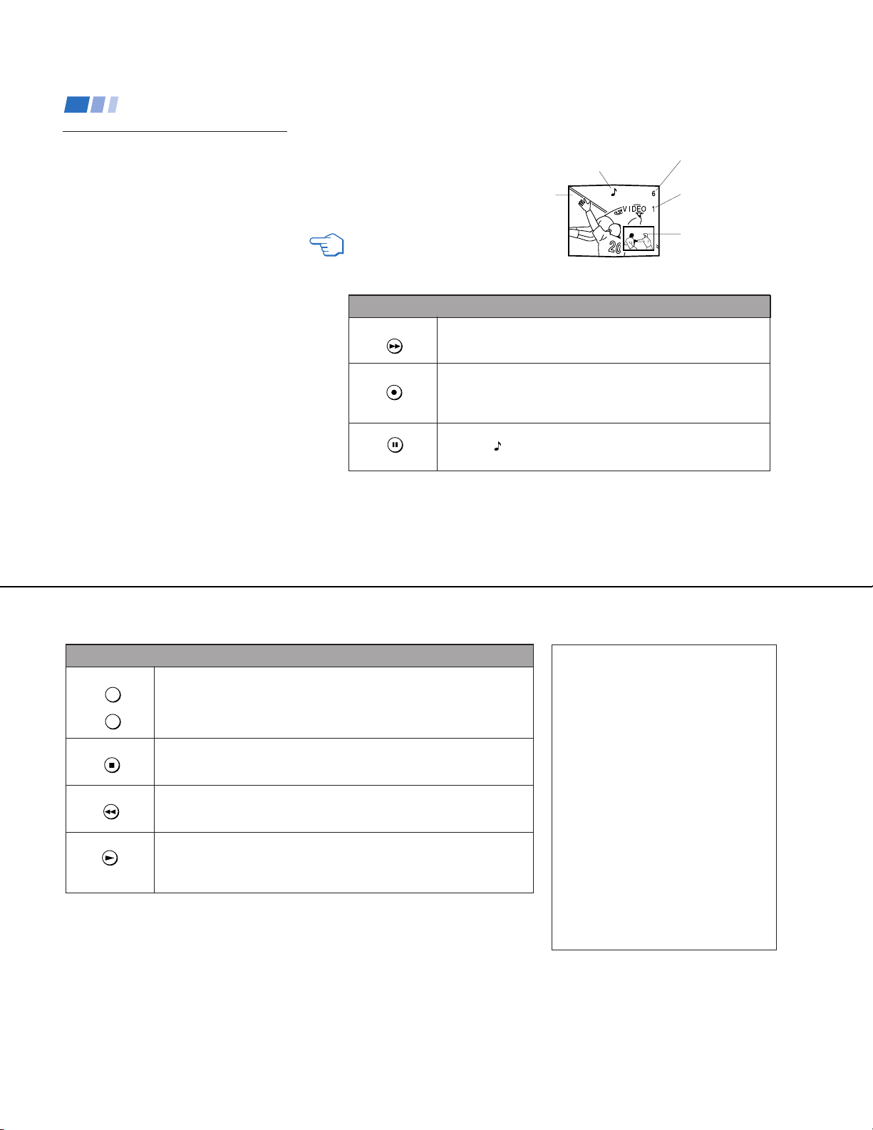
Press to alternate sound between the main picture and the window
picture. A
receiving sound.
The sound of the main
picture is received.
Main
picture
will appear for a few seconds to indicate which picture is
Input-source mode
or TV channel for
the main picture
Input-source mode
or TV channel for
the window picture
Window
picture
TV/VTR
+
CH
–
POSITION
FREEZE
SWAP
Use the Yellow Labeled Buttons for PIP Operations.
Press to change the TV channel in the window picture. (KV-27S65, 27V65 only)
For models KV-27S45, 27V45, you must press VTR/DVD (FUNCTION), then use
the main CH +/- buttons to change channels. (see right)
Press to move the location of the window picture (counterclockwise) around the
main picture.
Press to freeze the window picture. Great for copying down phone numbers,
addresses, recipes, etc.
Press FREEZE again to restore the previous screen(s).
Press to switch the audio and video of the main picture and the window picture.
Each time you press SWAP, the picture and sound of the two will be
Any channels being received through the AUX jack cannot be displayed as a
window picture. (KV-27S65, 27V65 only)
swapped
Changing channels with a single
tuner PIP
• KV-27S45, 27V45 only
1
Press TV/VIDEO until you reach the TV
input.
2
Press PIP (the window picture appears).
To change the window picture:
1
Press VTR/DVD (FUNCTION).
2
Press the main CH +/– buttons to change
channels.
To change the main picture:
1
Press TV (FUNCTION).
2
Press the main CH +/– buttons to change
.
channels.
Note
• If you have the same program in both the
window and the main picture and cannot
change the channel in the window; press
TV/VIDEO until you reach the TV input in the
main picture.
17
— 14 —
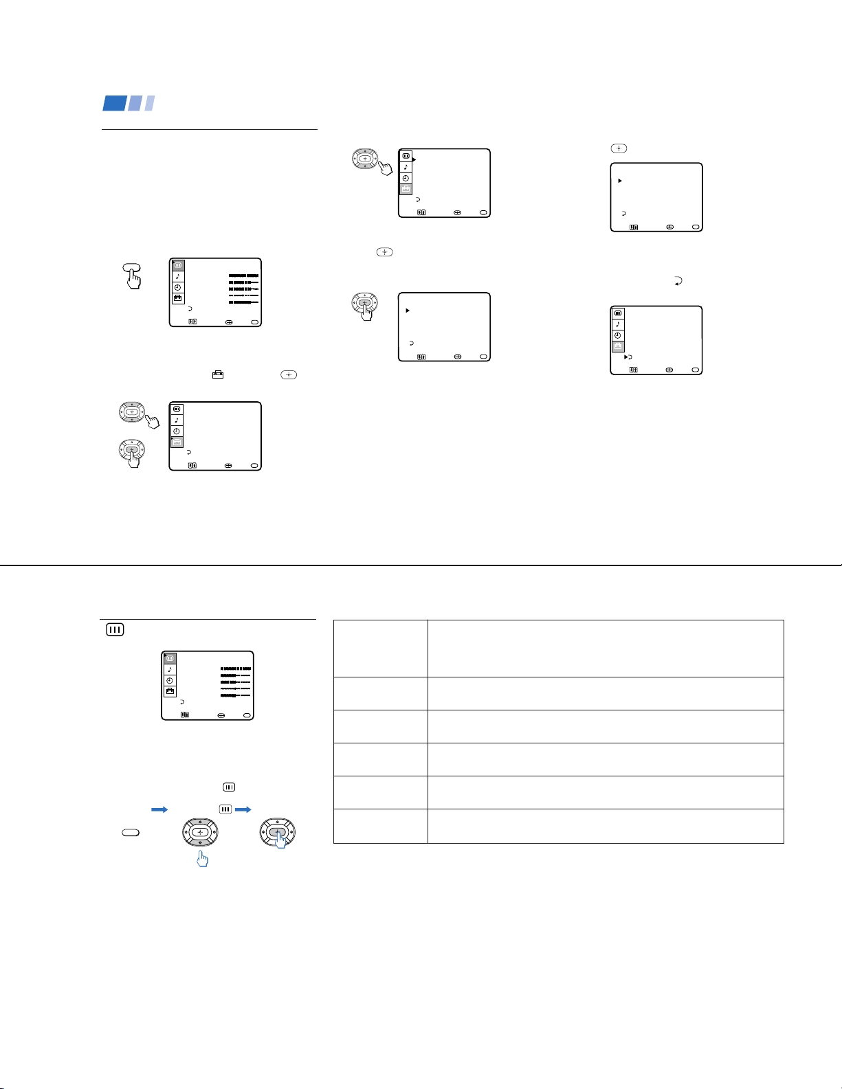
Using your Menus
Learning menu selection
Use the MENU button to access a menu and
use the select buttons (V or v) to alter settings.
Use the following example, in which we
activate the CABLE, to learn how to modify
settings.
1
Press the MENU button.
The main menu appears.
MENU
2
Press V or v to highlight the desired menu
(in this case SET UP
select it.
VIDEOŁ
MODE: VIVID
PICTURE Ł
BRIGHTNESS
COLOR Ł
HUE
SHARPNESSŁ
MENU
Move Select Exit
SET UP
CHANNEL SET UPŁ
FAVORITE CHANNELŁ
CHANNEL BLOCKŁ
VIDEO LABELŁ
CAPTION VISION:CC1
LANGUAGE: ENGLISH
MENU
Move Select Exit
MENU
) and press to
MENU
3
Press V or v to move to the desired option.
SET UP
CHANNEL SET UPŁ
FAVORITE CHANNELŁ
CHANNEL BLOCKŁ
VIDEO LABELŁ
CAPTION VISION:CC1
LANGUAGE: ENGLISH
MENU
4
Press .
Move Select Exit
MENU
Options for your selection will be
displayed.
CHANNEL SET UPŁ
Ł
CABLE: OFFŁ
CHANNEL FIX: OFFŁ
AUTO PROGRAM
CHANNEL SKIP/ADDŁ
CHANNEL CAPTIONŁ
MENU
Move Select Exit
MENU
KV-27S40 / 27S45 / 27S65 / 29SL40 / 29SL40A / 29SL40C/
29SL45 / 29SL65 / 29SL65C/ 29XL40M / 29XL40P / 29XT11A
5
Press V or v to make your selection and
press
.
CHANNEL SET UPŁ
Ł
CABLE: ONŁ
CHANNEL FIX: OFFŁ
AUTO PROGRAM
CHANNEL SKIP/ADDŁ
CHANNEL CAPTIONŁ
MENU
Move Select Exit
MENU
When you are finished making changes to the
selected menu, choose
MENU to return to
the main menu.
SET UP
CHANNEL SET UPŁ
FAVORITE CHANNELŁ
CHANNEL BLOCKŁ
VIDEO LABELŁ
CAPTION VISION:CC1Ł
LANGUAGE: ENGLISH
MENU
Move Select Exit
MENU
Notes
• Pressing MENU on the remote control will
allow you to exit from the menus at any
time.
• If any menu items are "blacked out", press
the ANT button on your remote control
until a channel number appears.
18
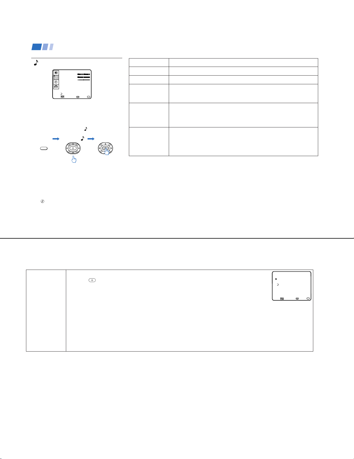
Using the VIDEO menu
VIDEOŁ
MODE: VIVID
PICTURE Ł
BRIGHTNESS
COLOR Ł
HUE
SHARPNESSŁ
MENU
Move Select Exit
For detailed information on using the remote
to modify menu settings, refer to “Learning
menu selection” on page 18.
To select the VIDEO menu:
Display Highlight Select
MENU
To restore the factory VIDEO
settings
Press RESET while the VIDEO menu is
displayed.
Adjustment
}
MENU
bars
MODE
Customized picture
viewing
PICTURE
Picture Adjustment
BRIGHTNESS
Picture Adjustment
COLOR
Picture Adjustment
HUE
Picture Adjustment
SHARPNESS
Picture Adjustment
(except KV-20V80)
VIVID: Select to receive a vivid, bright picture.
STANDARD: Select to receive a standard picture.
MOVIE: Select to receive a softened picture.
Adjust left to decrease picture contrast and soften the color.
Adjust right to increase picture contrast and create more vivid color.
Adjust left to darken the picture.
Adjust right to brighten the picture.
Adjust left to decrease color intensity.
Adjust right to increase color intensity.
Adjust left to decrease the green tones.
Adjust right to increase the green tones.
Adjust left to soften the picture.
Adjust right to sharpen the picture.
— 15 —
19
KV-27S40 / 27S45 / 27S65 / 29SL40 / 29SL40A / 29SL40C/
29SL45 / 29SL65 / 29SL65C/ 29XL40M / 29XL40P / 29XT11A
Using your Menus (continued)
Using the AUDIO menu
AUDIO
TREBLE Ł
BASS
BALANCE Ł
AUTO VOLUME: ON
SPEAKER: OFFŁ
AUDIO OUT: VARIABLE
OPTIONS
MENU
Move Select Exit
For detailed information on using the remote
to modify menu settings, refer to “Learning
menu selection” on page 18.
To select the AUDIO menu:
Display Highlight Select
MENU
To restore the factory AUDIO
settings
Press RESET while the AUDIO menu is
displayed.
z
Tip
Press for direct selection of an AUDIO setting.
20
}
MENU
Adjustment
bars
TREBLE
BASS
BALANCE
AUTO VOLUME
Stabilizes volume
SPEAKER
Custom selection of
audio output source
AUDIO OUT
Use to control the
TV's volume through
a stereo
Adjust left or right to decrease or increase higher pitched sound
Adjust left or right to decrease or increase low pitched sounds.
Adjust left or right to emphasize speaker volume.
(KV-27V40, 27V45, 27V65 only).
ON: Select to stabilize the volume when changing channels.
OFF: Select to turn AUTO VOLUME off.
ON: Select to listen to the sound from the TV speakers and a separate stereo
system.
OFF: Select to turn off the TV speakers and listen to the TV's sound only through
external audio system speakers.
AUDIO OUT can only be set when speakers are set to OFF.
VARIABLE: Sound output varies according to the TV settings.
Useful when you want to use your remote control to control the output of a
separate audio system.
FIXED: Sound output is held at a fixed level through your stereo.
OPTIONS
Enhanced audio
options
With the OPTIONS menu open:
1 Press
to access the feature you want to change.
2 Press V or v to cycle through the options.
MTS: Press V or v to select one of the following options:
STEREO: Select for stereo reception when viewing a broadcast in stereo.
SAP: Select to listen to bilingual broadcast. (Non-SAP programs will be muted when this feature is selected.)
MONO: Select for mono reception (use to reduce noise during stereo broadcasts.)
Quick MTS access: Press MTS on your remote control to cycle through the MTS options.
EFFECT: Press V or v to select one of these customized effects based on the program you are viewing:
SRS: Produces a dynamic three dimensional sound for stereo audio signals.
(KV-27V40, 27V45, 27V65 only)
SURROUND: Simulates theater quality sound (only for stereo programs).
(KV-20V80, 27S40, 27S45, 27S65 only)
SIMULATED: Adds a surround-like effect to mono programs.
(KV-27V40, 27V45, 27V65 only)
OPTIONSŁ
Ł
MTS: STEREOŁ
EFFECT: SRSŁ
MENU
Move Select Exit
MENU
21
— 16 —
ON/OFF TIMERŁ
Ł
___Ł
--:-- AM_h CH____Ł
MENUŁ
SUN 12:00 AM
Move Select Exit
MENU
Using your Menus (continued)
CHANNEL SKIP/ADDŁ
33Ł
SKIPŁ
MENUŁ
use (0-9) or (CH+/-)
to select the channel
Move Select Exit
MENU
KV-27S40 / 27S45 / 27S65 / 29SL40 / 29SL40A / 29SL40C/
29SL45 / 29SL65 / 29SL65C/ 29XL40M / 29XL40P / 29XT11A
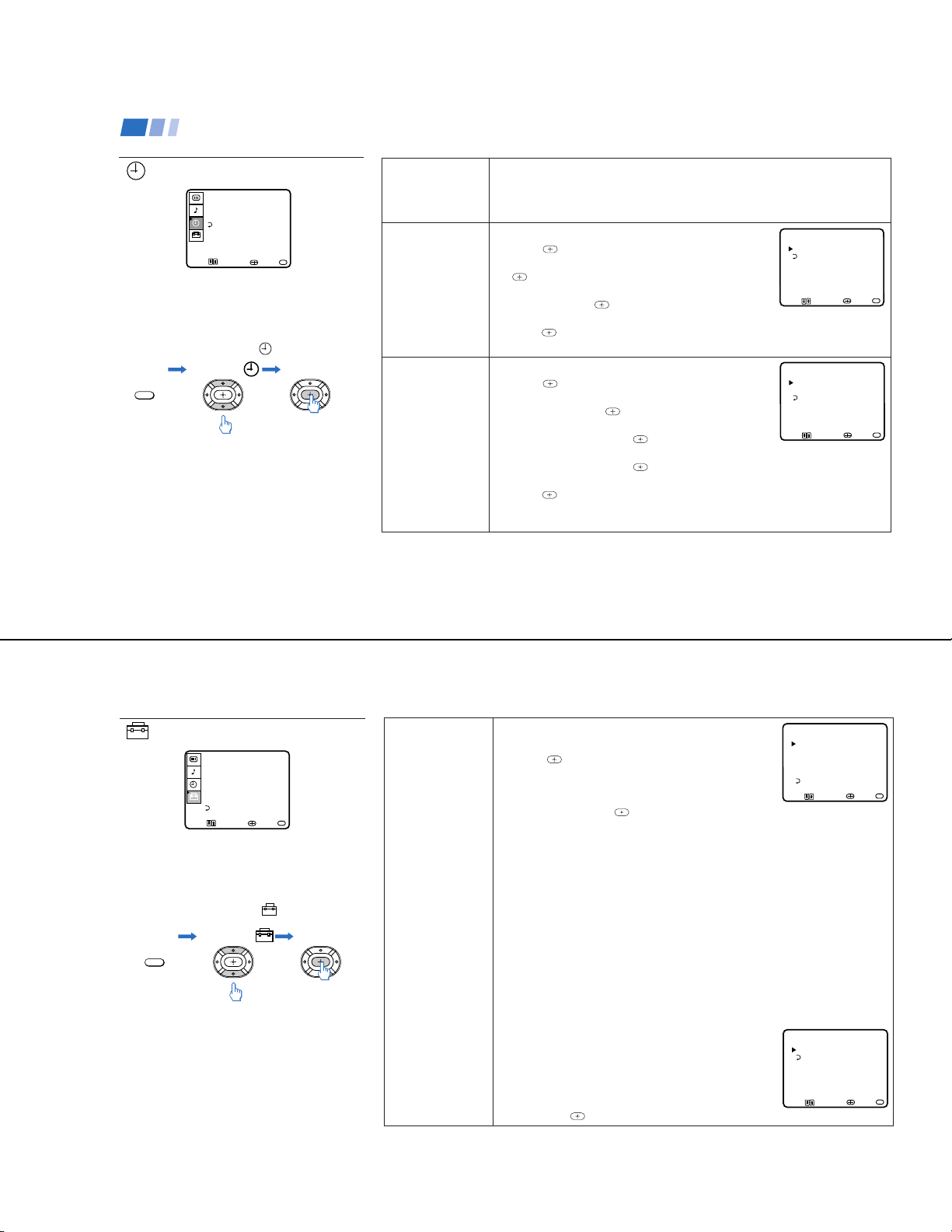
Using the TIMER menu
TIMERŁ
DAYLIGHT
CURRENT TIME SET Ł
ON/OFF TIMER
MENU
Move Select Exit
For detailed information on using the remote
to modify menu settings, refer to “Learning
menu selection” on page 18.
To select the TIMER menu:
Display Highlight Select
MENU
To cancel the ON/OFF TIMER
function
Press RESET while the TIMER menu is
displayed.
Tip
z
Set daylight saving time before setting the clock. Any
loss of power will cause these settings to be erased.
22
SAVING: YES
MENU
DAYLIGHT
SAVING
Automatically adjusts
the time.
CURRENT
TIME SET
Necessary for the
TIMER.
ON/OFF TIMER
Wake up or
scheduled viewing.
Spring: Select YES to compensate for Daylight Saving Time.
The current time automatically moves one hour ahead.
Fall: Select NO at the end of Daylight Saving Time.
The current time moves back one hour.
CURRENT TIME SET menu will appear.
1 Press
.
2 Press V or v until the current day is displayed. Press
to select.
3 Press V or v until the current hour and AM/PM is
displayed. Press
to select.
CURRENT TIME SETŁ
Ł
___--:-- AMŁ
MENU
Move Select Exit
MENU
4 Press V or v until the current minute is displayed,
.
press
The clock is set. Press MENU to exit.
ON/OFF TIMER menu will appear.
1 Press
.
2 Press V or v until the desired day or range of days
is displayed. Press
to select.
3 Indicate the time that you want the TV to turn on by
pressing V or v and then
.
4 Set the time duration (maximum of 6 hours) by
pressing V or v and then
.
5 Press V or v until you reach the desired channel.
to select.
Press
The ON/OFF TIMER is now set. Press MENU to exit.
When you perform AUTO PROGRAM, all ON/OFF TIMER settings will be erased.
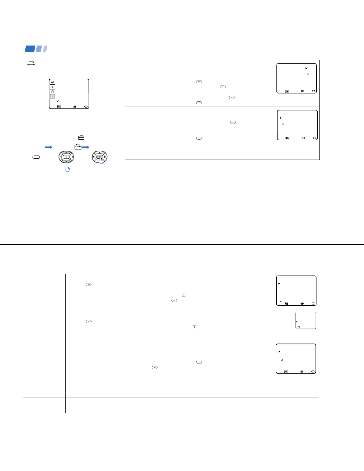
Using the SET UP menu
SET UP
CHANNEL SET UPŁ
FAVORITE CHANNELŁ
CHANNEL BLOCKŁ
VIDEO LABELŁ
CAPTION VISION:CC1
LANGUAGE: ENGLISH
MENU
Move Select Exit
For detailed information on using the remote
to modify menu settings, refer to “Learning
menu selection” on page 18.
To select the SET UP menu:
Display Highlight Select
MENU
Notes
• The FAVORITE CHANNEL feature is not
available for the AUX input.
• Your remote control can be programmed to
operate your cable box. (see page 28)
MENU
CHANNEL
SET UP
Basic set up
options for
viewing
With the CHANNEL SET UP menu open:
1 Use V or v to access the feature you want to change.
2 Press
to select the feature.
CABLE: Select ON if your TV is connected to a cable
system. (After setting CABLE, you will need to run
AUTO PROGRAM.)
CHANNEL SET UPŁ
Ł
CABLE: ONŁ
CHANNEL FIX: OFFŁ
AUTO PROGRAM
CHANNEL SKIP/ADDŁ
CHANNEL CAPTIONŁ
MENU
Move Select Exit
CHANNEL FIX: Press and then use the V or v buttons to set the TV's input
to one of the following options:
2-6: When a cable box is connected to the VHF/UHF input. Press DBS/CABLE
(FUNCTION) and then CH +/– to change channels.
AUX 2-6: When a cable box is connected to AUX and a cable or antenna is
connected to VHF/UHF. You can alternate between the two inputs by pressing
ANTon the remote control. (KV-27S65, 27V65 only)
VIDEO 1: When you have connected video equipment (e.g. A/V receiver) and
you want the TV input fixed to it. You will be able to alternate between video
sources using the A/V receiver.
OFF: When you want to switch CHANNEL FIX off.
Press ANT on the remote control until you reach a picture.
ON/OFF TIMER and CHANNEL BLOCK settings will be erased when
CHANNEL FIX is set.
AUTO PROGRAM: Instructs the TV to automatically program all receivable
channels.
CHANNEL SKIP/ADD:
With the CHANNEL SKIP/ADD window open:
1 Place the cursor next to SKIP or ADD. (only
one option will be displayed)
2 Choose the desired channel using CH +/–, or
by selecting with the 0-9 buttons and pressing
ENTER.
3 Press
to activate.
— 17 —
MENU
23
KV-27S40 / 27S45 / 27S65 / 29SL40 / 29SL40A / 29SL40C/
29SL45 / 29SL65 / 29SL65C/ 29XL40M / 29XL40P / 29XT11A
Using your Menus (continued)
Using the SET UP menu
(continued)
SET UP
CHANNEL SET UPŁ
FAVORITE CHANNELŁ
CHANNEL BLOCKŁ
VIDEO LABELŁ
CAPTION VISION:CC1
LANGUAGE: ENGLISH
MENU
Move Select Exit
For detailed information on using the remote
to modify menu settings, refer to “Learning
menu selection” on page 18.
To select the SET UP menu:
Display Highlight Select
MENU
To erase the CHANNEL BLOCK
settings
Press RESET while the SET UP menu is
displayed.
MENU
CHANNEL
SET UP
(continued)
Basic set up
options for
viewing
CHANNEL
BLOCK
Prevent child access
to certain channels.
.
CHANNEL CAPTION: You will be able to label up to 12
channels with their call letters.(except KV-20V80)
With the CHANNEL CAPTION menu open:
1 Press
channel, and press
and then V or v to access the desired
again.
2 Press V or v to display the first letter or number
of the caption and press
3 Press
to activate. To erase a caption, press RESET.
You will be able to block two channels
to select it.
.
With the CHANNEL BLOCK window open:
1 Choose 1 or 2 and press
.
2 Press V or v to display the channel you want to
block.
3 Press
to activate.
CHANNEL CAPTIONŁ
- ___Ł
____
MENUŁ
Move Select Exit
CHANNEL BLOCKŁ
Ł
1.CH___Ł
2.CH___Ł
MENU
Select a program
Move Select Exit
MENU
When you select the blocked channel, BLOCKED
will appear on the screen. CAPTION VISION will also be blocked.
When you perform AUTO PROGRAM, your CHANNEL BLOCK settings will be erased.
MENU
24
FAVORITE
CHANNEL
Quick access to
favorite channels
VIDEO LABEL
Easy recognition of
connected equipment
(e.g. DBS, VHS, etc.)
Setting FAVORITE CHANNEL:
1 Press
and then V or v to select AUTO or MANUAL. (Selecting AUTO will display the last five channels
chosen with the remote control.)
2 Press V or v to move the cursor to 1, 2, 3, 4 or 5 and press
3 Press V or v to access the desired channel and press
.
.
4 For KV-27S65, 27V65 only, you can preview your favorite channels in the window picture, to do so, set
FAVORITE CHANNELŁ
MODE: AUTO
PREVIEW: ONŁ
1.___Ł
2.___Ł
3.___Ł
4.___Ł
5.___
MENUŁ
Move Select Exit
PREVIEW to ON.
Using FAVORITE CHANNEL:
1 Press
2 Press V or v to access the channel you want to watch, and press
when in normal viewing mode. Your FAVORITE CHANNEL options will appear.
.
3 For models KV-27S65, 27V65 only, if PREVIEW is ON, a window picture displays your favorite channels as you cycle
through the options.
This feature allows you to label each input mode so that you can easily identify connected equipment (e.g. you
can label VIDEO 1 as VHS). (except KV-20V80)
With the VIDEO LABEL window open:
1 Press V or v to move to the input mode you want to label and press
2 Press V or v to choose the label and press
.
.
VIDEO LABELŁ
Ł
VIDEO 1: VIDEO 1Ł
VIDEO 2: VIDEO 2Ł
VIDEO 3: VIDEO 3Ł
MENUŁ
Ł
Ł
Ł
Move Select Exit
VIDEO LABEL Options:
Video 1: VHS, 8mm, BETA, LD, GAME, DBS, DVD, WEB, RECEIVER, DTV.
Video 2/3: VHS, 8mm, BETA, LD, GAME, DBS, DVD, WEB, RECEIVER, DTV.
When VIDEO LABEL is set to WEB, the picture will darken, creating an ideal picture for WebTV viewing.
125 ESPN
14 ABC
48 CBS
16 HBO
5 CBC
Exit
MENU
MENU
LANGUAGE
(except Canadian models)
You can change the language of your menus to either ENGLISH or ESPAÑOL.
25
— 18 —
Operating video equipment
KV-27S40 / 27S45 / 27S65 / 29SL40 / 29SL40A / 29SL40C/
29SL45 / 29SL65 / 29SL65C/ 29XL40M / 29XL40P / 29XT11A
Programming the remote
You can use the supplied remote control to
operate Sony or non-Sony video equipment.
1
Press CODE SET.
2
Press VTR/DVD (FUNCTION).
3
Use the 0-9 buttons to key in the
manufacturer's code number from the
following chart.
4
Press ENTER.
VCR manufacturer code numbers
Manufacturer Code
Sony 301, 302, 303
Aiwa 338, 344
Broksonic 319, 317
Canon 309, 308
Daewoo 341, 312, 309
Emerson 319, 320, 316, 317, 318,341
Fisher 330, 335
Funai 338
General Electric 329, 304, 309
Go Video 322
Goldstar 332
Hitachi 306, 304, 305,338
JVC 314, 336, 337, 345, 346, 347
Kenwood 314, 336, 332, 337
LXI (Sears) 332, 305, 330, 335, 338
26
Magnavox 308, 309, 310
Mitsubishi/MGA 323, 324, 325, 326
NEC 314, 336, 337
Panasonic 308, 309, 306, 307
Philips 308, 309, 310
Pioneer 308
Quasar 308, 309, 306
RCA/PROSCAN 304, 305, 308, 309, 311,
Realistic 309, 330, 328, 335, 324, 338
Sansui 314
Samsung 322, 313, 321
Sanyo 330, 335
Sharp 327, 328
Sylvania 308, 309, 338, 310
Symphonic 338
Technics 309, 308
Toshiba 312, 311
Wards 327, 328, 335, 331, 332
Zenith 331
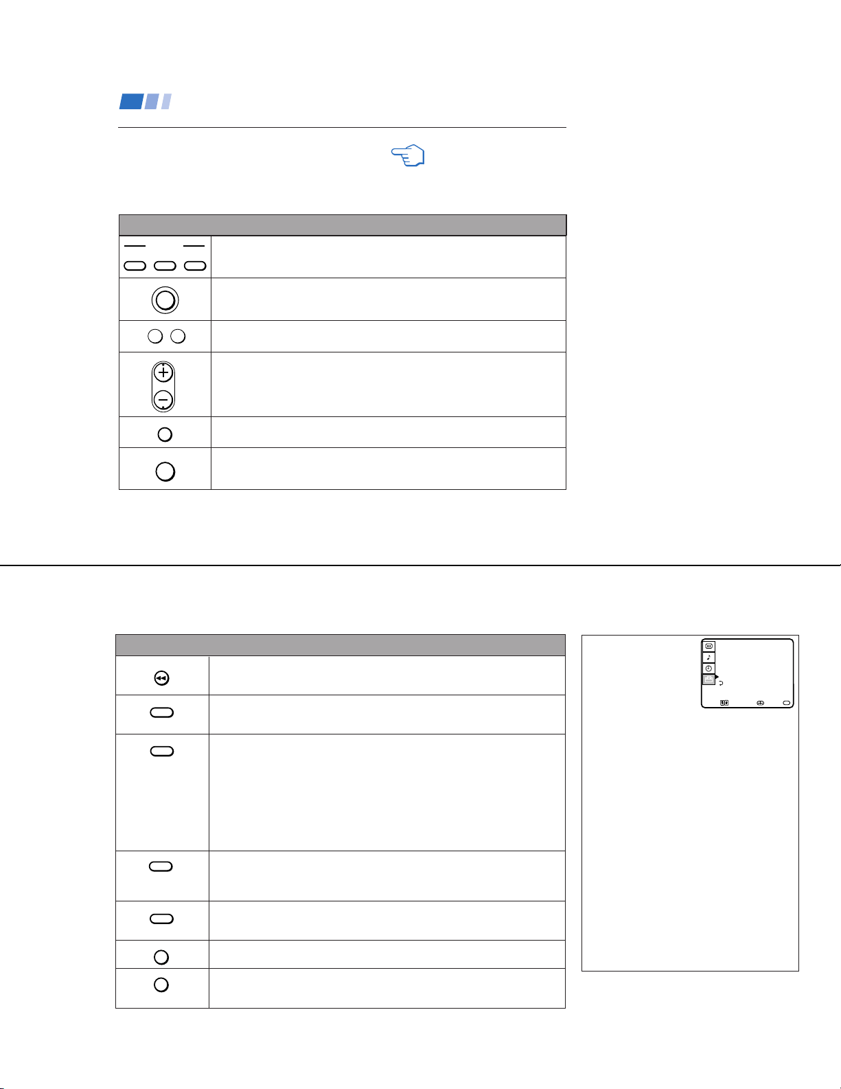
Operating a VCR
312, 313, 310, 329
Buttons on the
remote control
To turn on or off
To select a channel
directly
To change
channels
To record
To play
Press VTR (POWER).
Press the 0 – 9 buttons.
Press CH +/–.
Press ( and r
simultaneously.
Press (.
To stop
To fast forward
To rewind the tape
To pause
To search the
picture forward or
backward
To change input
mode
Press p.
Press ).
Press 0.
Press P.
To resume normal playback,
press again or press (.
Press ) or 0 during
playback.
To resume normal playback,
release the button.
Press TV/VTR.
Tips z
• In some rare cases, you may not be able to operate
your non-Sony video equipment with the supplied
remote control. In this case, please use the
equipment’s own remote control.
• The code numbers for Sony VCR's are assigned at the
factory as follows:
VHS VCR 301 (preset code
for the supplied
remote control)
8 mm VCR 302
Beta, ED Beta VCRs 303
• When you remove the batteries, the code number may
revert to the factory setting.
MDP (Multi Disc Player)
manufacturer code numbers
Manufacturer Code
Sony 701
Panasonic 704, 710
Pioneer 702
Operating an MDP
To turn on or off
To play
To stop
To pause
To search the picture
forward or backward
To search the
chapter forward or
backward
Buttons on the remote
control
Press VTR/DVD (POWER).
Press (.
Press p.
Press P.
To resume normal playback,
press again or press (.
Press ) or 0 during
playback.
To resume normal playback,
press (.
Press CH +/–.
DVD (Digital Versatile Disc)
manufacturer code numbers
Manufacturer Code
Sony 751
Panasonic 753
Pioneer 752
RCA 755
Toshiba 754
Operating a DVD
player
To turn on or off
To play
To stop
To pause
To search the picture
forward or backward
To search the
chapter forward or
backward
To select chapters
directly
MENU
To move cursor in
menu
Buttons on the remote
control
Press VTR/DVD (POWER).
Press (.
Press p.
Press P.
To resume normal playback,
press again or press (.
Press ) or 0 during
playback.
To resume normal playback,
press (.
Press CH +/–.
0–9 + ENTER.
Press to display DVD menu.
Use your arrow buttons
V v, B b.
27
— 19 —
KV-27S40 / 27S45 / 27S65 / 29SL40 / 29SL40A / 29SL40C/
29SL45 / 29SL65 / 29SL65C/ 29XL40M / 29XL40P / 29XT11A
Operating a cable box or DBS receiver
Programming the remote
You can program the supplied remote control
to operate a cable box or DBS receiver.
1
Press CODE SET.
2
Press DBS/CABLE (FUNCTION).
3
Use the 0-9 buttons to key in the
manufacturer's code number from the
following chart.
4
Press ENTER.
For more details on operating the
cable box or DBS receiver
Refer to the operating instructions that were
supplied with the equipment.
28
If the remote control doesn’t work
• First, try repeating the setup procedures
using the other codes listed for your
equipment.
Tips z
• If more than one code number is listed, try entering
them one by one until you come to the correct code for
your equipment.
• If you enter a new code number, the code number you
previously entered at that setting is erased.
• In some rare cases, you may not be able to operate
your equipment with the supplied remote control. In
this case, use the equipment’s own remote control
unit.
• Whenever you remove the batteries the code numbers
may revert to the factory setting and must be reset.
Manufacturer code numbers
(cable box)
Manufacturer
Hamlin/Regal
Jerrold/G. I.
Oak
Panasonic
Pioneer
Scientific Atlanta
Tocom
Zenith
222, 223, 224, 225, 226
201, 202, 203, 204, 205, 206,
Manufacturer code numbers
(DBS receiver)
Manufacturer
Sony
General Electric
Hitachi
Hughes
Panasonic
RCA/PROSCAN
Toshiba
801 (preset code for
remote control)
Code
207, 208, 218
227, 228, 229
219, 220, 221
214, 215
209, 210, 211
216, 217
212, 213
Code
802
805
804
803
802, 808
806, 807
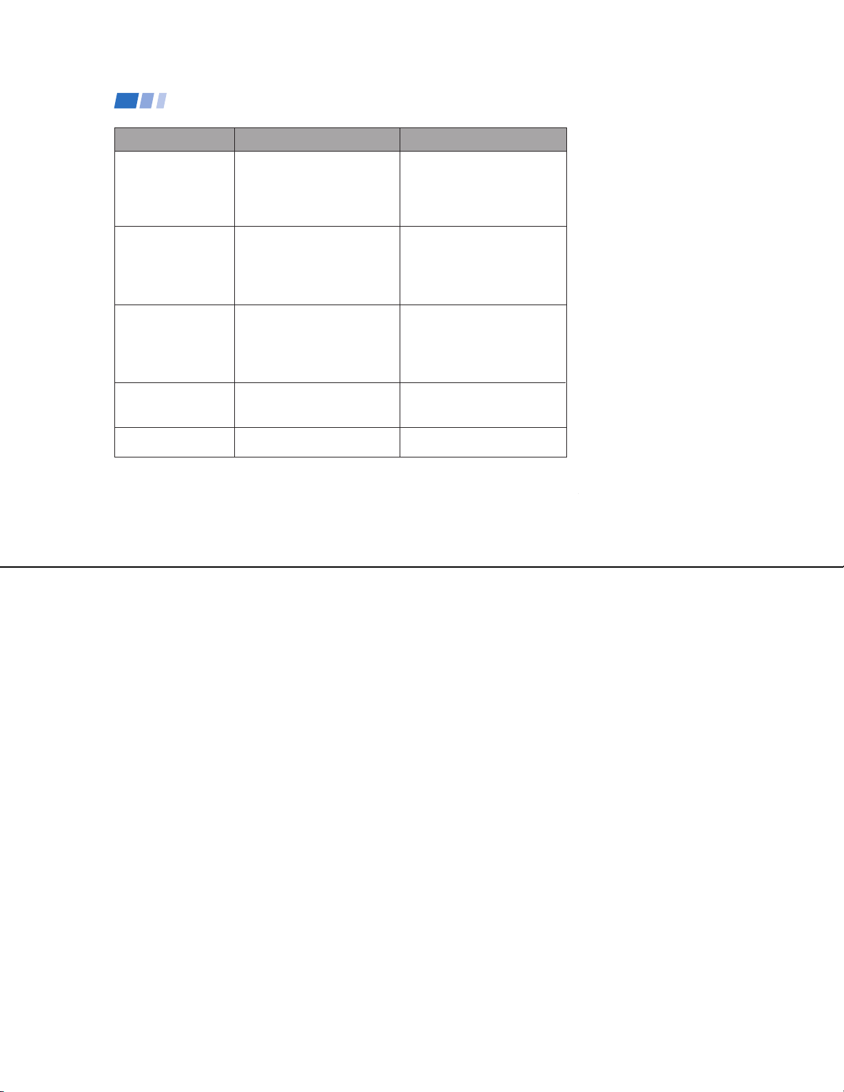
Troubleshooting
Consult the table below; it suggests solutions to specific problems. If you need more information, consult the operating instructions guide.
Problem What it could be What you can do
•
Cannot Operate Single Tuner PIP
(KV-27S45, 27V45)
A red light keeps flashing on the
TV for more than a few seconds
TV makes a noise when turned
on
Screen is not lit and there is no
sound
Poor or no picture (screen lit),
good sound
Good picture, no sound
No color
• VCR may not be connected to your TV properly.
• VCR may not be turned on.
• Your TV may need service.
• This is a normal function of your TV.
• Power cord may not be plugged in.
• Batteries may not have been placed with the correct
polarity.
• TV/VIDEO setting may be incorrect.
• VIDEO menu settings may not be adjusted correctly.
• Antenna/cable connections may be faulty.
• VIDEO LABEL inputs may be set to WEB. (This label
darkens the screen for ideal WebTV viewing.)
• Sound may be set to MUTE.
• Your TV may be set to SAP.
• Speaker may not be set correctly.
• Color settings may not be adjusted correctly.
Ensure that you have set your VCR correctly. (see page 7)
• Call your local Sony service center.
• Press TV/VIDEO until you receive a channel.
• Perform AUTO SET UP again by pressing the SET UP
button on your TV. (see page 13)
• Readjust your VIDEO menu settings.(see page 19)
• Check your VIDEO LABEL settings. (see page 25)
• Check the MTS setting in the AUDIO menu. (see page 21)
• Check your SPEAKER settings. (see page 20)
• Adjust the COLOR settings in the VIDEO menu.
(see page 19)
29
— 20 —
Troubleshooting (continued)
Problem What it could be What you can do
Only snow and noise
appear on the screen
Cannot receive upper
channels (UHF) when
using an antenna
Cannot receive any
channels when using
cable
Cannot gain enough
volume when using a
cable box
TV is fixed to one
channel
If, after reading these operating instructions, you have additional questions related to the use of your Sony
television, please call our Direct Response Center at 1-800-222-SONY (7669).
• CABLE setting may not be set
correctly in the SET UP menu.
• Antenna/cable connections may
not be correct.
• TV may be set to AUX mode.
• CABLE setting may not be correct
in the SET UP menu.
• CABLE setting may not be set
correctly in the SET UP menu.
• Volume may not be adjusted on
your cable box.
• CHANNEL FIX settings may not
be correct.
• Ensure that you have selected the
correct CABLE mode in the
SET UP menu. (see page 23)
• Press ANT on your remote
control to change the input mode.
(see page 15)
•
Ensure that CABLE is set to OFF
in the SET UP menu. (see page 23)
• Use AUTO PROGRAM to add
receivable channels that are not
presently in TV memory. (see
page 24)
• Ensure that CABLE is set to ON
in the SET UP menu. (see page 23)
• Use AUTO PROGRAM to add
receivable channels that are not
presently in TV memory. (see
page 24)
• Press TV (FUNCTION) and
adjust the TV's volume.
• Check your CHANNEL FIX
settings. (see page 23)
KV-27S40 / 27S45 / 27S65 / 29SL40 / 29SL40A / 29SL40C/
29SL45 / 29SL65 / 29SL65C/ 29XL40M / 29XL40P / 29XT11A
30
— 21 —
KV-27S40 / 27S45 / 27S65 / 29SL40 / 29SL40A / 29SL40C/
29SL45 / 29SL65 / 29SL65C/ 29XL40M / 29XL40P / 29XT11A
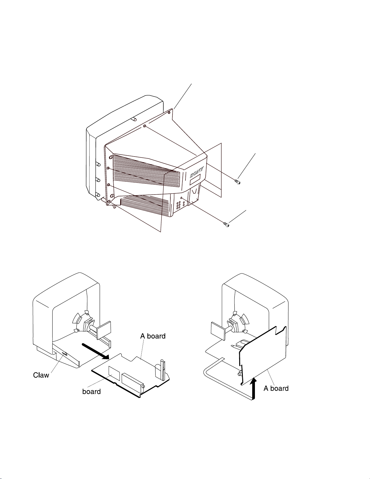
2-1. REAR COVER REMOVAL
SECTION 2
DISASSEMBLY
Rear Cover
Seven screws
(BVTP 4X16)
One screw
(BVTP 3X12)
2-2. A BOARD REMOVAL 2-3. SERVICE POSITION
P
— 22 —
 Loading...