


Sony kv28wf3 schematic
SERVICE MANUAL AE- 4 CHASSIS
MICROFILM
MODEL
COMMANDER DEST CHASSIS NO.
KV-28WF3A
KV-28WF3B
KV-28WF3D
KV-28WF3E
KV-28WF3K
RM-862 Italian SCC-K43L-A
RM-862 French SCC-K45N-A
RM-862 AEP SCC-K41N-A
RM-862 Spanish SCC-K42L-A
RM-862 OIRT SCC-K44M-A
MODEL
COMMANDER DEST CHASSIS NO.
KV-32WF3A
KV-32WF3B
KV-32WF3D
KV-32WF3E
KV-32WF3K
RM-862 Italian SCC-K43K-A
RM-862 French SC C-K45M -A
RM-862 AEP SCC-K41M-A
RM-862 Spanish SCC-K42K-A
RM-862 OIRT SCC-K44L-A
TRINITRON
1
®
COLOR TV
®
KV-28WF3/32WF3
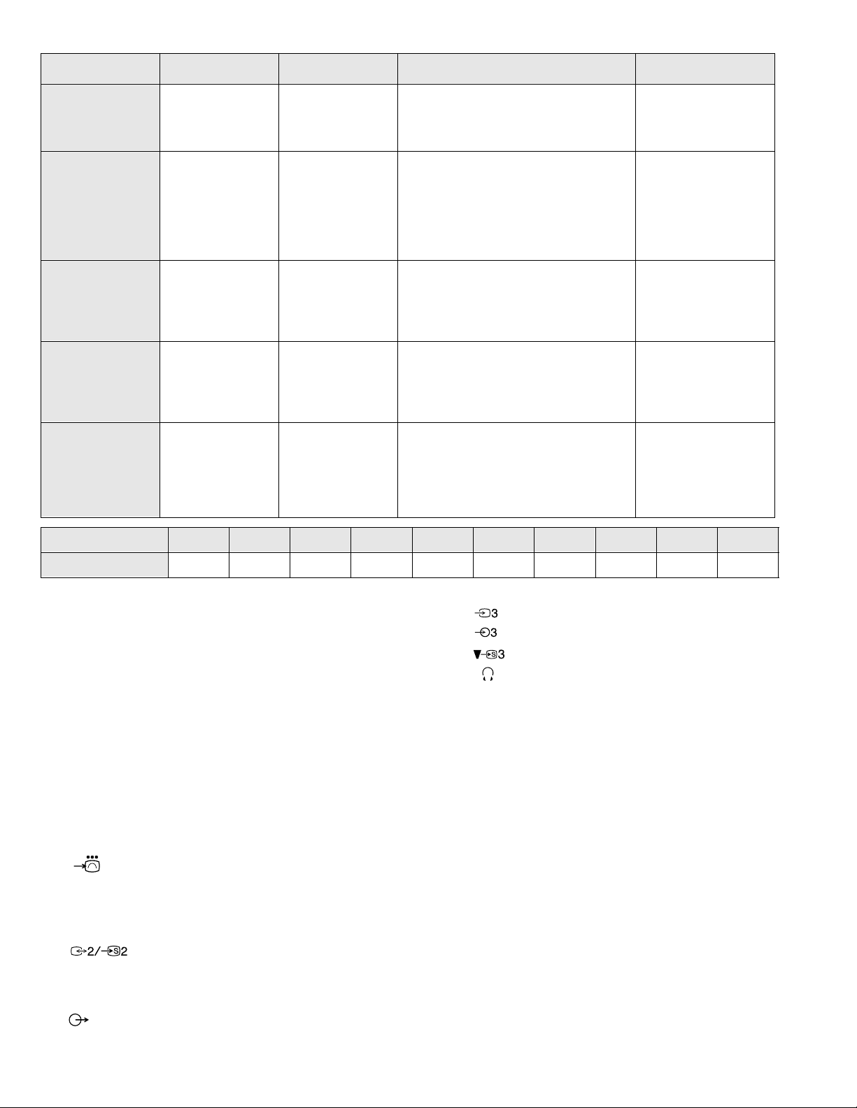
ITEM MODEL Television System Stereo System Channel Coverage Color System
ITALIA VHF : A-H2 (C) UHF : 21-69 PAL
Italian B/G/H, D/K GERMAN Stereo
French B/G/H, D/K, L, I GERMAN/NICAM
Stereo
AEP B/G/H, D/K GERMAN Stereo
B/G/H VHF : E2-E12 UHF : E21-E69
CABLE TV (1) : S1-S41
CABLE TV (2) : S01-S05, M1-M10, U1-U10
L VHF : F02-F10 UHF : F21-F60
CABLE : B-Q B/G/H VHF : E2-E12
UHF : E21-E69
CABLE TV (1) : S1-S41
CABLE TV (2) : S01-S05, M1-M10, U1-U10
ITALIA VHF : A-H2 (C) UHF : 21-69
I UHF : B21-B69
PA L B/G/ H VHF : E2-E12 UHF : E21-E69
CABLE TV (1) : S1-S41
CABLE TV (2) : S01-S05, M1-M10, U1-U10
ITALIA VHF : A-H2 (C) UHF : 21-69
D/K VHF : R01-R12 UHF : R21-R69
PAL
NTSC4.43, NTSC3.58
(VIDEO IN)
PAL, SECAM
NTSC4.43, NTSC3.58
(VIDEO IN)
PAL, SECAM
NTSC4.43, NTSC3.58
(VIDEO IN)
Spanish B/G/H, D/K GERMAN/NICAM
Stereo
OIRT B/G/H, D/K GERMAN/NICAM
STEREO
MODEL 28WF3A 28WF3B 28WF3D 28WF3E 28WF3K 32WF3A 32WF3B 32WF3D 32WF3E 32W F3K
Power Consumption 108 W 119 W 119 W 119 W 119 W 118 W 132 W 132 W 132 W 132 W
[PICTURE TUBE]
KV -28WF3 Super Trinitron
Approx. 71cm (28 inches)
(Approx. 66cm picture measured
diagonally)
110 degree deflection
KV -32WF3 Super Trinitron
Approx. 82cm (32 inches)
PAL B/G VHF : E2-E12 UHF : E21-E69
CABLE TV (1) : S1-S41
CABLE TV (2) : S01-S05, M1-M10, U1-U10
ITALIA VHF : A-H2 (C) UHF : 21-69
D/K VHF : RO1-R20 UHF : B21-B69
PA L B/G/ H VHF : E2-E12 UHF : E21-E69
CABLE TV (1) : S1-S41
CABLE TV (2) : S01-S05, M1-M10, U1-U10
ITALIA VHF : A-H2 (C) UHF : 21-69
D/K VHF : R01-R12 UHF : R21-R69
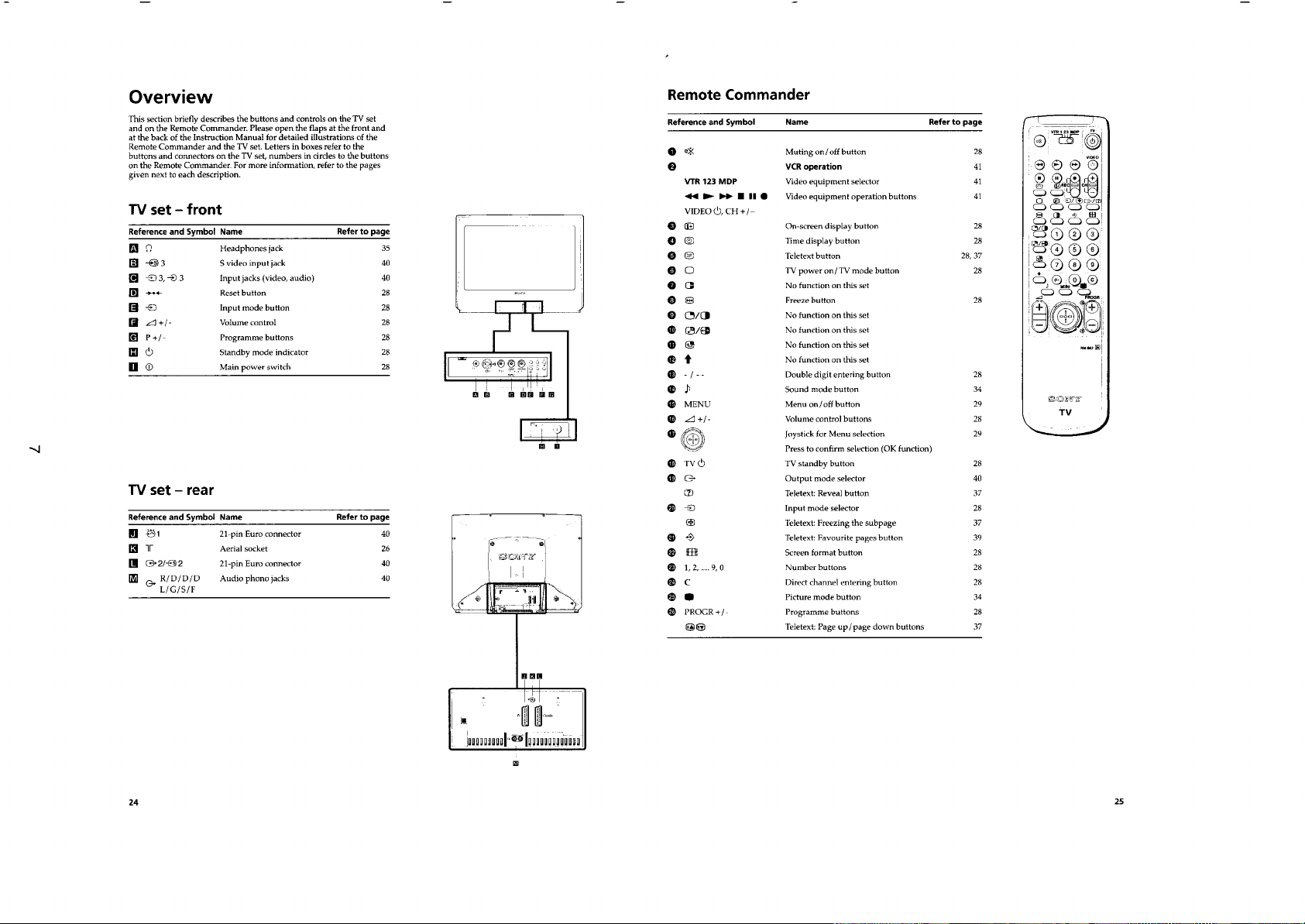
[FRONT]
Video input - phono jack
Audio inputs - phono jacks
S Video input 4 pin DIN
Headphone jacks : stereo minijack
Sound output 2 x 20W (Music Power)
Power requirements 220 - 240V
PAL, SECAM
NTSC4.43, NTSC3.58
(VIDEO IN)
(Approx. 76cm picture measured
diagonally)
110 degree deflection
Dimensions
KV-28WF3 Approx 690x535x534mm
KV-32WF3 Approx 789x602x576mm
Input/Output Terminals
[REAR]
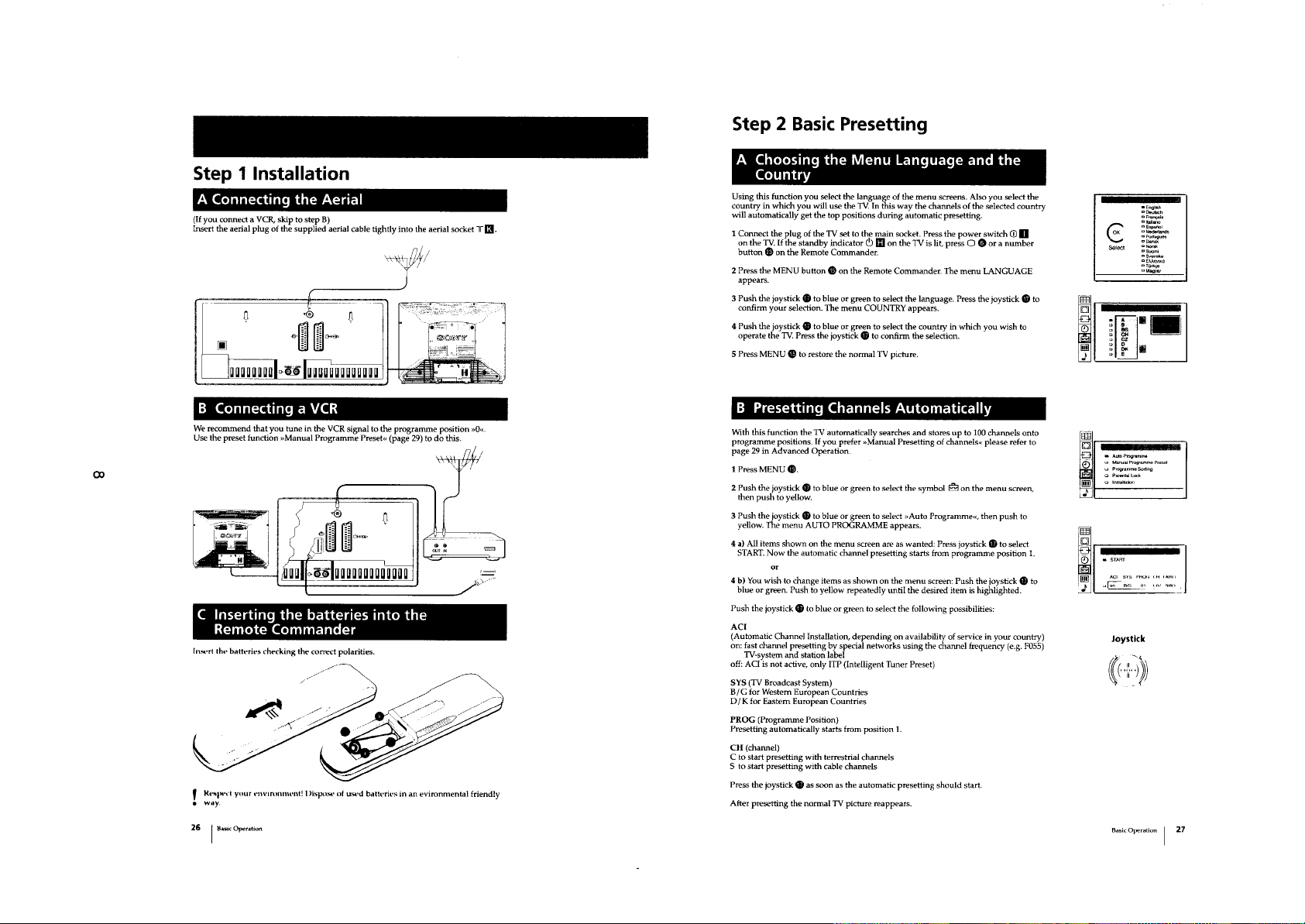
1 21-pin Euro connector (CENELEC standard).
- Inputs for Audio and Video signals.
- Inputs for RGB.
- Outputs of TV Video and Audio signals.
21-pin Euro connector.
- inputs for Audio and Video signals.
- inputs for S Video.
- outputs for Audio and Video signals (selectable).
Phono Jack
- Outputs for Audio Signals
Weight
KV-28WF3 Approx 38kg
KV-32WF3 Approx 55.5kg
Supplied accessories RM-862 Remote Commander (1)
IEC designated R6 battery (2)
Other features DNR (Digital Noise Reduction),
Digital Plus.
NICAM*, FASTEXT, TOPTEXT
(KV-28WF3B/28WF3E/28WF3K/
*
32WF3B/32WF3E/32WF3K only)
[RM-862]
Remote control system infrared control
Power requirements 3V dc (2 Batteries) R6 (Size AA)
Dimensions Approx 210x56x24mm (w/h/d)
Weight Approx 110g (Not including battery)
2

KV-28WF3/32WF3
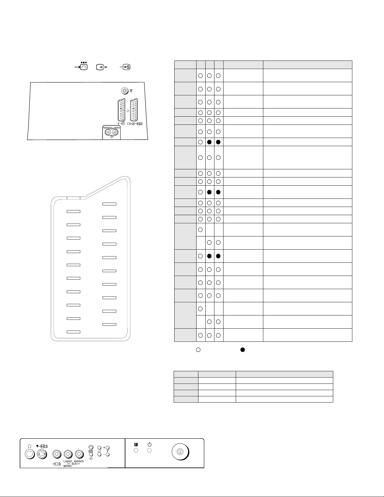
Model Na me
Item
Pal Comb OFF OFF OFF OFF OFF
PIP OFF OFF OFF OFF OFF
RGB Priority OFF OFF OFF ON OFF
Woofer Box OFF OFF OFF OFF OFF
Scart 1 ON ON ON ON ON
Scart 2 ON ON ON ON ON
Front in (3) ON ON ON ON ON
Scart 4 OFF OFF OFF OFF OFF
Projector OFF OFF OFF OFF OFF
AKB in 16:9 mode ON ON ON ON ON
Norm B/G/H ON ON ON ON ON
Norm I OFF ON OFF OFF OFF
Norm D/K ON ON ON ON ON
Norm AUS OFF OFF OFF OFF OFF
KV-28WF3A
KV-32WF3A
KV-28WF3B
KV-32WF3B
KV-28WF3D
KV-32WF3D
KV-28WF3E
KV-32WF3E
KV-28WF3K
KV-32WF3K
Norm L OFF ON OFF OFF OFF
Norm SAT OFF OFF OFF OFF OFF
Norm M OFF OFF OFF OFF OFF
Teletext ON ON ON ON ON
Nicam Stereo OFF ON OFF ON ON
Language Preset Italian French German Spanish OIRT
3
KV-28WF3/32WF3
21 pin connector (1 , 2 / 2 )
21
20
19
18
17
16
15
14
13
12
11
10
9
8
7
6
5
4
3
2
1
Pin No 1 2 4 Signal Signal level
1 Audio output B
2
3
4 Ground (audio)
5 Ground (blue)
6 Audio input A
7 Blue input 0.7 +/- 3dB, 75 ohms positive
8 Function select
9 Ground (green)
10 Open
11 Green Green signal : 0.7 +/- 3dB, 75 ohms,
12 Open
13 Ground (red)
14 Ground (blanking)
15
_ (S signal Chroma
16 Blanking input
17 Ground (video
18 Ground (video
19 Video output 1V +/- 3dB, 75ohms, positive sync 0.3V
20
_ Video input
21 Common ground
(right)
Audio output B
(right)
Audio output A
(left)
(left)
(AV control)
_ _ Red input 0.7 +/- 3dB, 75 ohms, positive
input)
(Ys signal)
output)
input)
_ _ Video input 1V +/- 3dB, 75ohms, positive sync 0.3V
Y (S signal)
(plug, shield)
Standard level : 0.5V rms
Output impedence : Less than 1kohm*
Standard level : 0.5V rms
Output impedence : More than 10kohm*
Standard level : 0.5V rms
Output impedence : Less than 1kohm*
Standard level : 0.5V rms
Output impedence : More than 10kohm*
High state (9.5-12V) : Part mode
Low state (0-2V) : TV mode
Input impedence : More than 10K ohms
Input capacitance : Less than 2nF
positive
0.3 +/- 3dB, 75 ohms, positive
High state (1-3V) Low state (0-0.4V)
Input impedence : 75 ohms
(-3+10dB)
(-3+10dB)
1V +/- 3dB, 75ohms, positive sync 0.3V
(-3+10dB)
Connected Not Connected (open) * at 20Hz - 20kHz
Pin No Signal Signal level
1 Ground
2 Ground
3 Y (S signal) input 1V+/- 3dB 75 ohm, positive Sync 0.3V -3/+10dB
4 C (S signal) input 0.3V+/- 3dB 75 ohm, positive Sync
4

KV-28WF3/32WF3
TABLE OF CONTENTS
Section Title Page Section Title Page
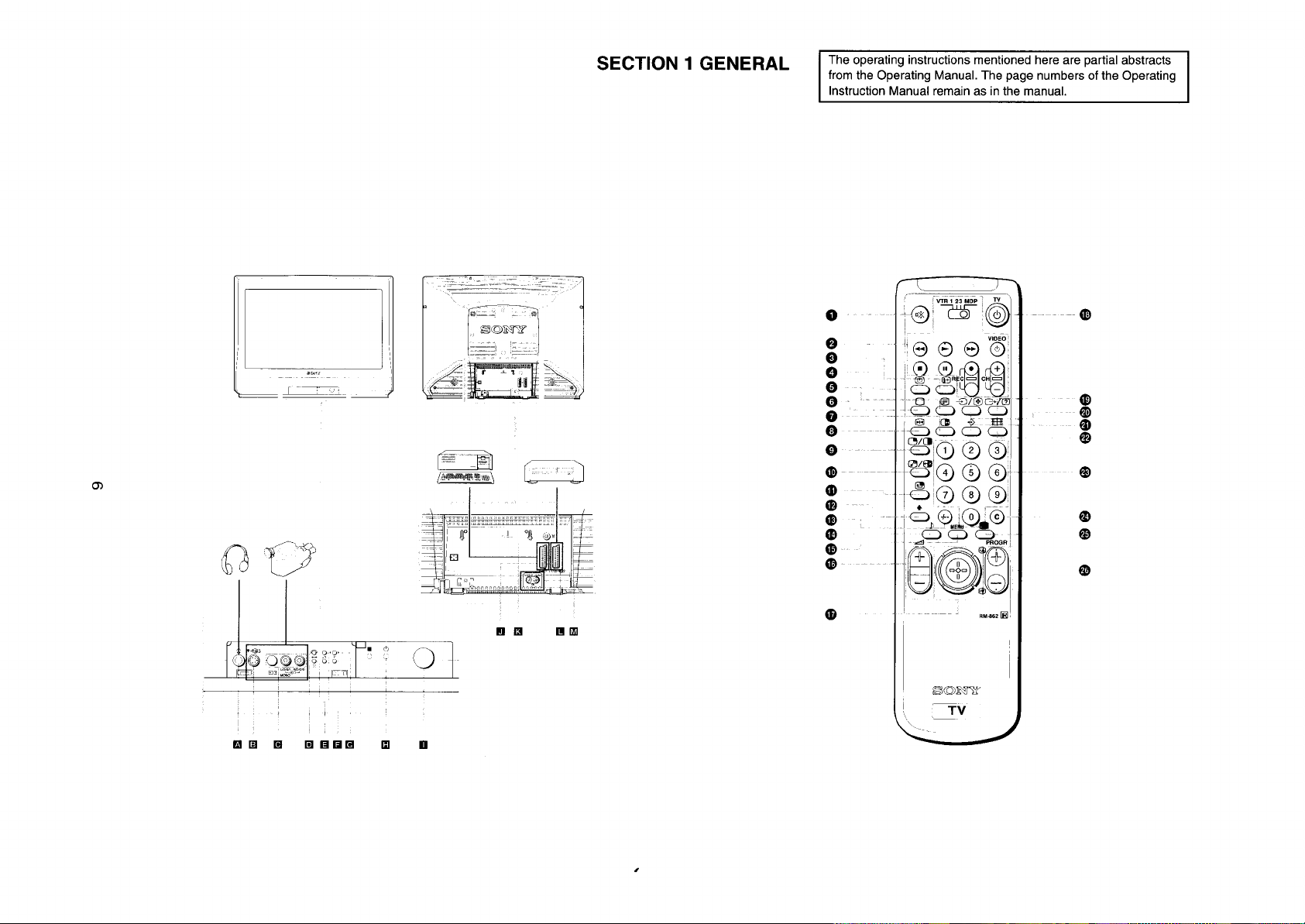
1. GENERAL
5. DIAGRAMS
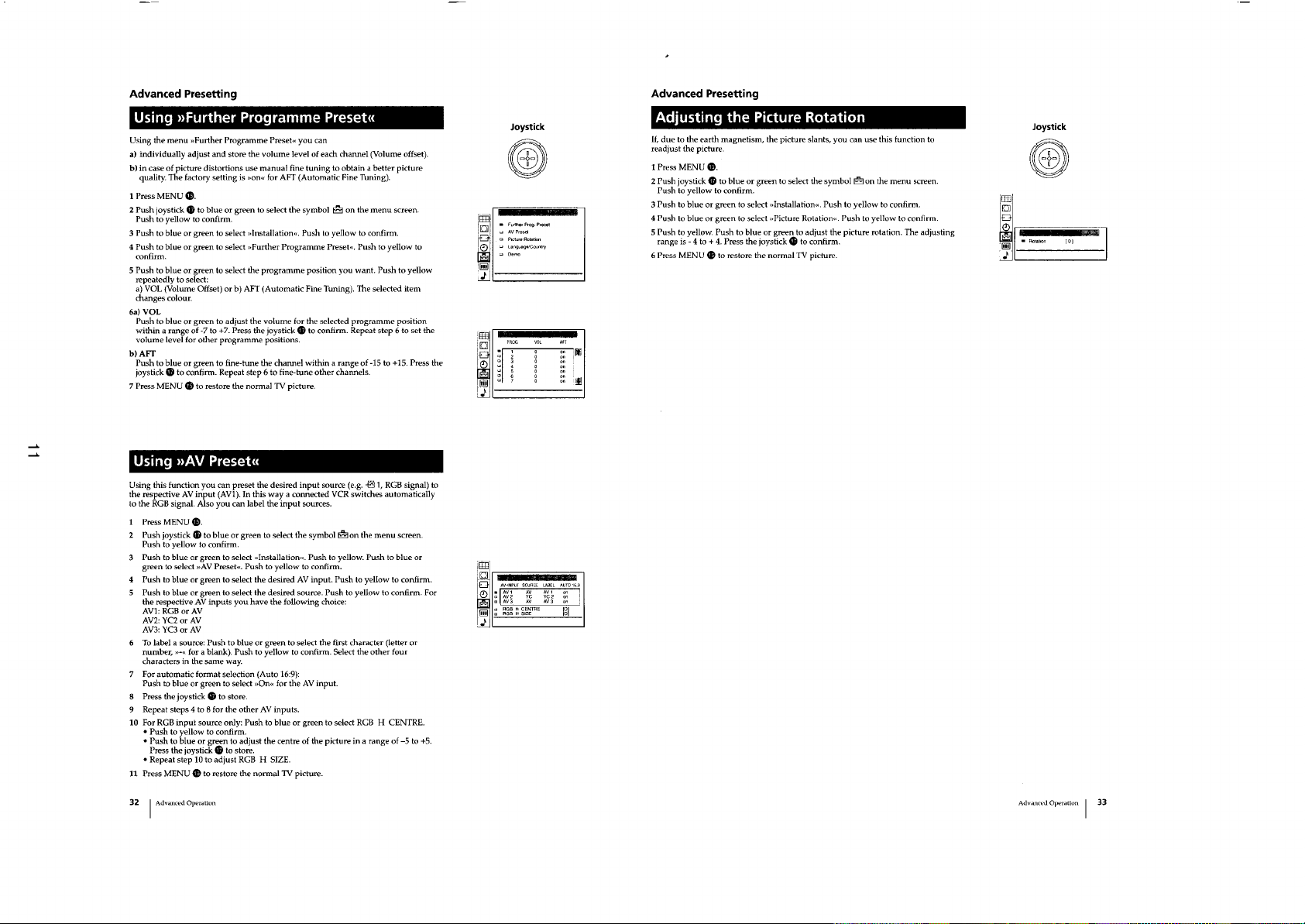
Overview .....................7
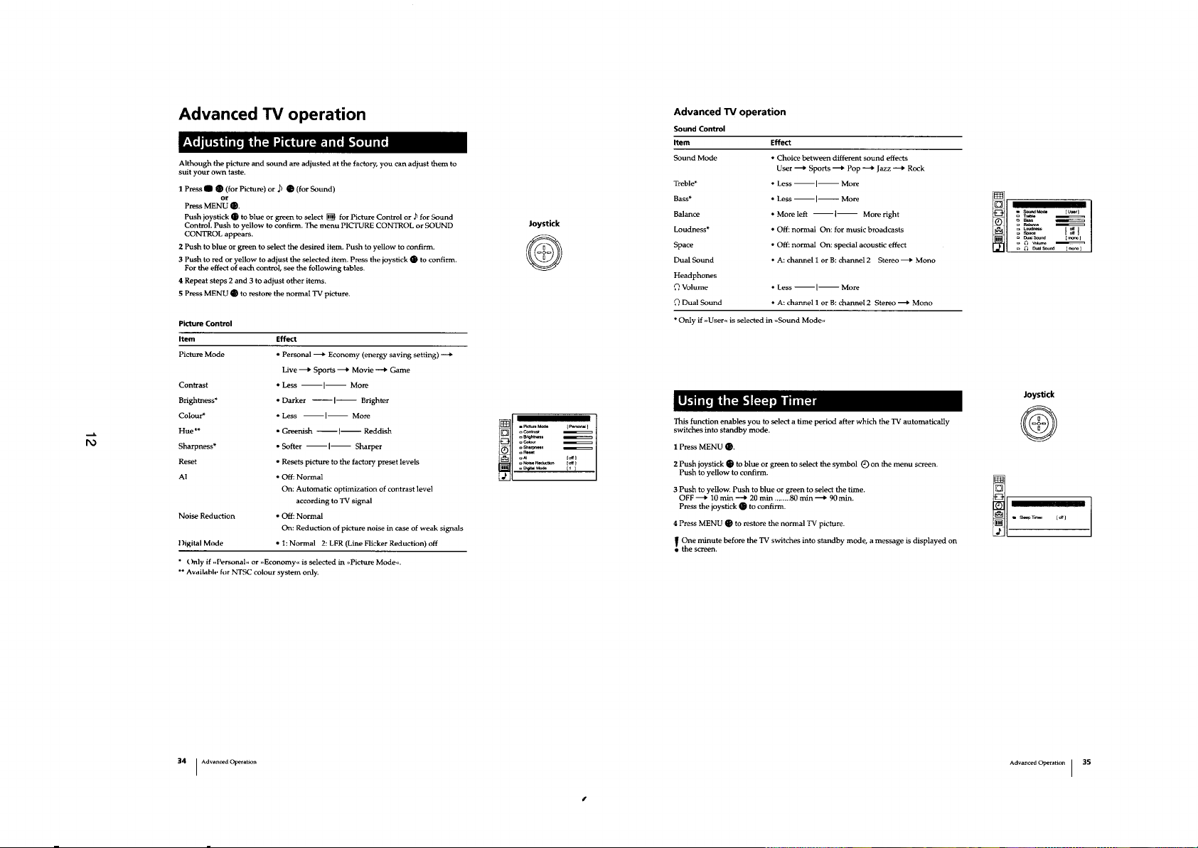
Basic Operation .....................8
Advanced Operation .....................9
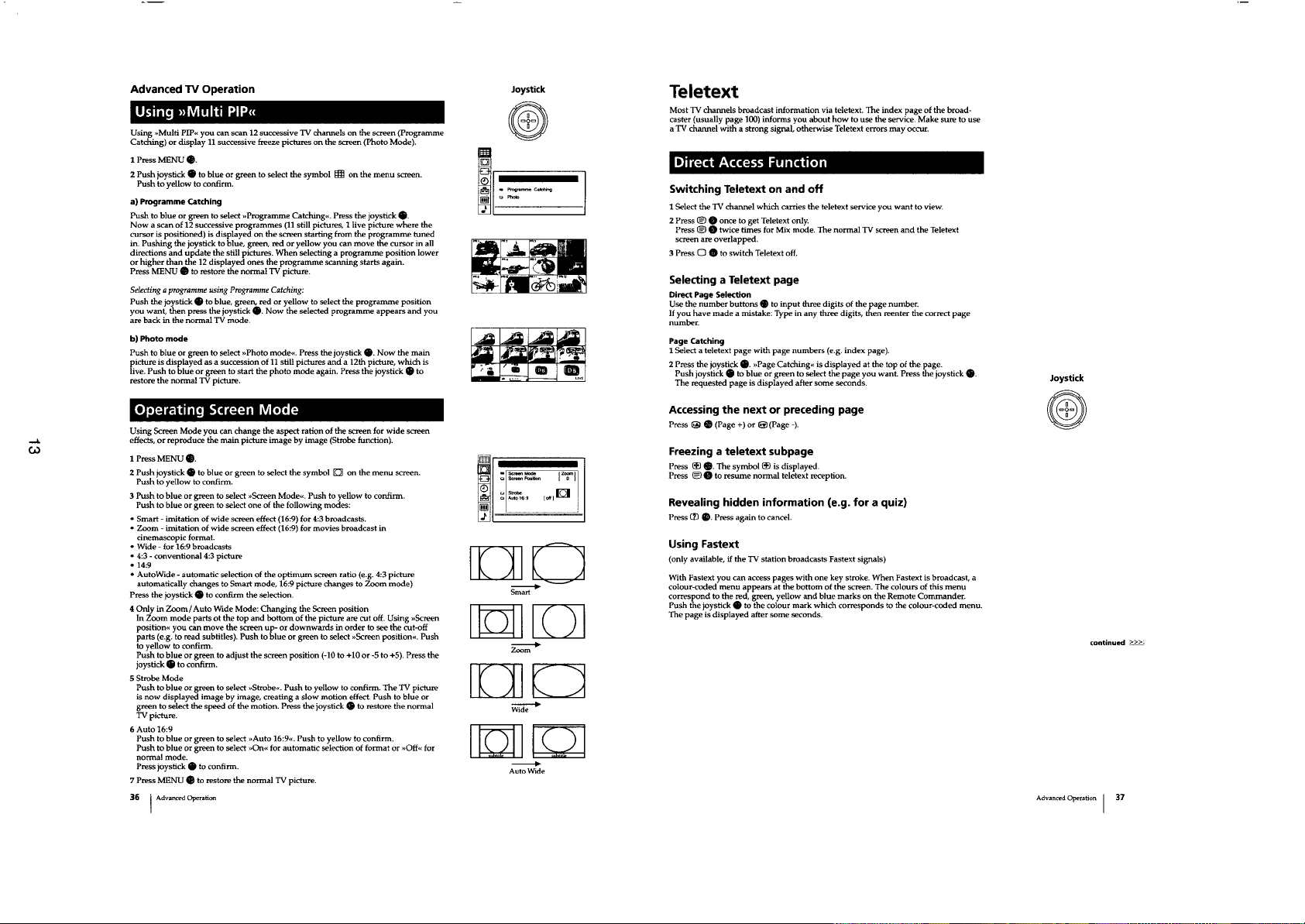
T e let ext Operation ............ .... .....13
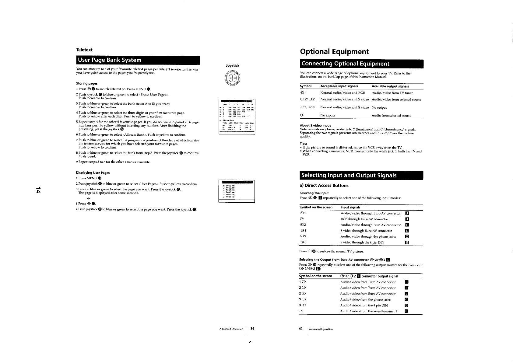
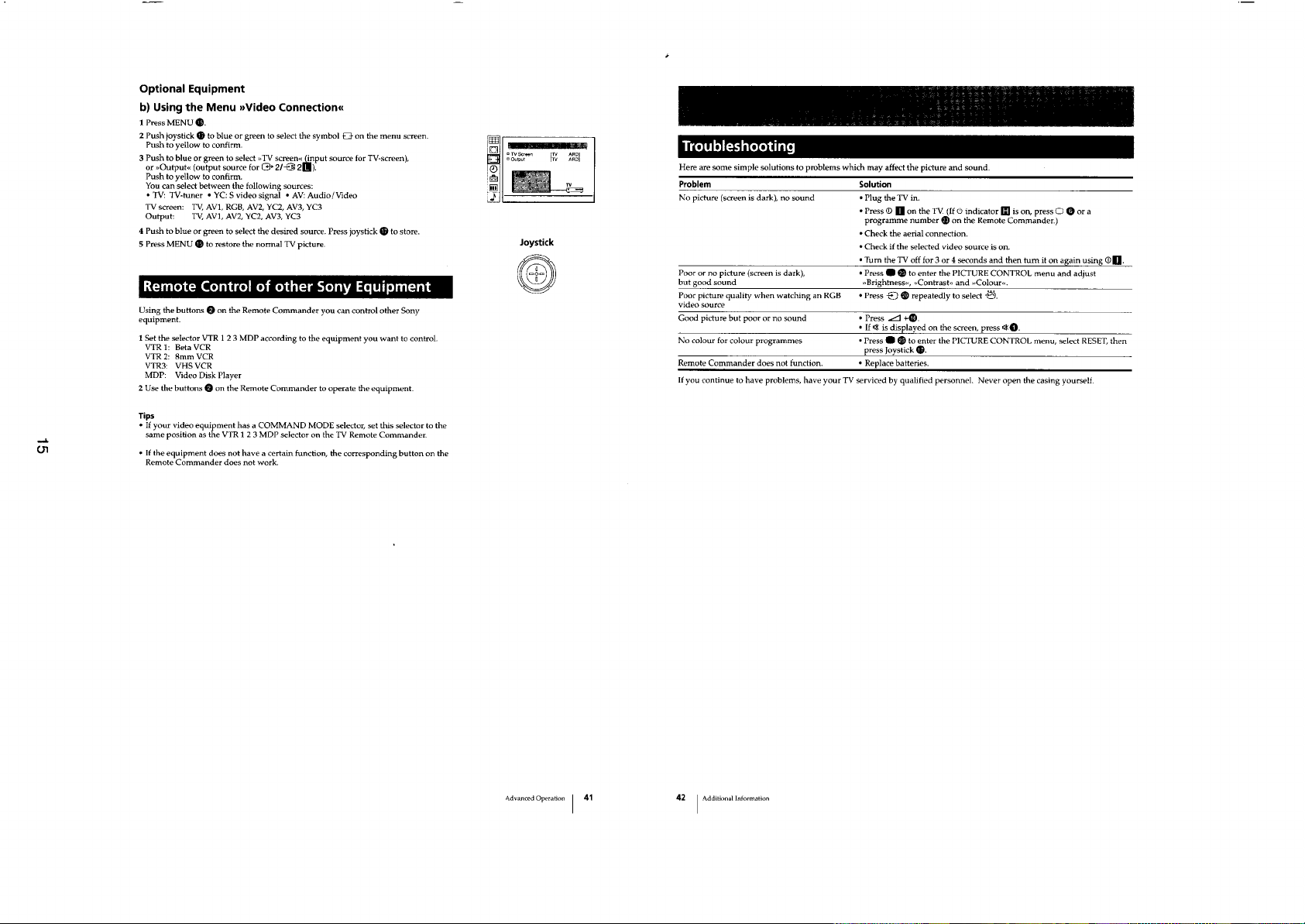
Optional Equipment .....................15
Additional Information .....................16
2. DISASSEMBLY
2-1. Rear Cover Removal .....................17
2-2. Chassis Assy Removal ................ ... ..17
2-3. Service Position .....................17
2-4. G Board Removal .....................17
2-5. A Board Removal .....................18
2-6. Picture Tube Removal .....................18
2-7. Removal and Replacement of th e
Main Bracket Bottom Plates .....................19
3. SET-UP ADJUSTMENTS
3-1. Beam Landing .....................20
3-2. Convergence .....................21
3-3. Focus .....................23
3-4. Screen [G2] White Balance .....................23
(Adjustment in the service mode
with remote commander)
5-1. Block Diagram (1) .....................31
Block Diagram(2) .....................34
Block Diagram(3) .....................35
Block Diagram(4) .....................37
Block Diagram(5) .....................39
Block Diagram(6) .....................42
5-2. Circuit Board Location .....................43
5-3. Schematic Diagrams and
Printed Wiring Boards .....................43
* A Board .....................47
* C Board .....................57
* D Board .....................63
* G Board .....................67
* VM Board .....................71
* B Board .....................79
5-4. Semiconductors .....................87
5-5. IC Blocks .....................90
6. EXPLODED VIEWS
6-1. Chassis .....................91
6-2. Picture Tube .....................92
7. ELECTRICAL PARTS LIST .....................94
4. CIRCUIT ADJUSTMENTS
4-1. Electrical Adjustments ................ ... ..24
4-2. Volume Electrical Adjustments .....................28
4-3. Test mode 2: .....................29
CAUTION
SHORT CIRCUIT THE ANODE OF THE PICTURE TUBE AND THE
ANODE CAP TO THE METAL CHASSIS, CRT SHIELD, OR THE
CARBON PAINTED ON THE CRT, AFTER REMOVAL OF THE
ANODE CAP
WARNING !!
AN ISOLATING TRANSFORMER SHOULD BE USED DURING ANY
SERVICE WORK TO AVO I D PO SSIBLE SHOCK HAZARD D U E TO
LIVE CHASSIS. THE CHASSIS OF THIS RECEIVER IS DIRECTLY
CONNECTED TO THE POWER LINE.
SAFETY-RELATED COMPONENT WARNING !!
COMPONENTS IDENTIFIED BY SHADING AND MARKED ON
THE SCHEMATIC DIAGRAMS, EXPLODED VIEWS AND IN THE
P ARTS LIST ARE CRITICAL FOR SAFE OPERATION. REPLACE
THESE COMPONENTS WITH SONY PARTS WHOSE PART NUMBERS
APPEAR AS SHOWN IN THIS MANUAL OR IN SUPPLEMENTS
PUBLISHED BY SONY.
ATTENTION
APRES AVOIR DECONNECTE LE CAP DE’LANODE,
COURT-CIRCUITER L’ ANODE DU TUBE CATHODIQUE ET
CELUI DE L’ANODE DU CAP AU CHASSIS METALLIQUE
DE L’APPAREIL, OU AU COUCHE DE CARBONE PEINTE
SUR LE TUBE CATHODIQUE OU AU BLINDAGE DU TUBE
CATHODIQUE.
ATTENTION !!
AFIN D’EVITER TOUT RISQUE D’ELECTROCUTI ON PR OVENANT
D’UN CHÁSSIS SOUS TENTION, UN TRANSFORMATEUR
D’ISOLEMENT DOIT ETRE UTILISÈ LORS DE TOUT DÈPANNAGE.
LE CHÁSSIS DE CE RÈCEPTEUR EST DIRECTMENT RACCORDÈ
Á L’ALIMENTATION SECTEUR.
ATTENTION AUX COMPOSANTS RELATIFS Á LA
SÈCURITÈ !!
LES COMPOSANTS IDENTIFIÈS PAR UNE TRAME ET PAR UNE
MARQUE SUR LES SCHÈMAS DE PRINCIPE, LES VUES
EXPLOSÈES ET LES LISTES DE PIECES SONT D’UNE IMPORTANCE
CRITIQUE POUR LA SÈCURITÈ DU FONCTIONNEMENT, NE LES
REMPLACER QUE PAR DES COMPSANTS SONY DONT LE NUMÈRO
DE PIÈCE EST INDIQUÈ DANS LE PRÈSENT MANUEL OU DANS
DES SUPPLÈMENTS PUBLIÈS PAR SONY.
5
SECTION 2
DISASSEMBLY
17
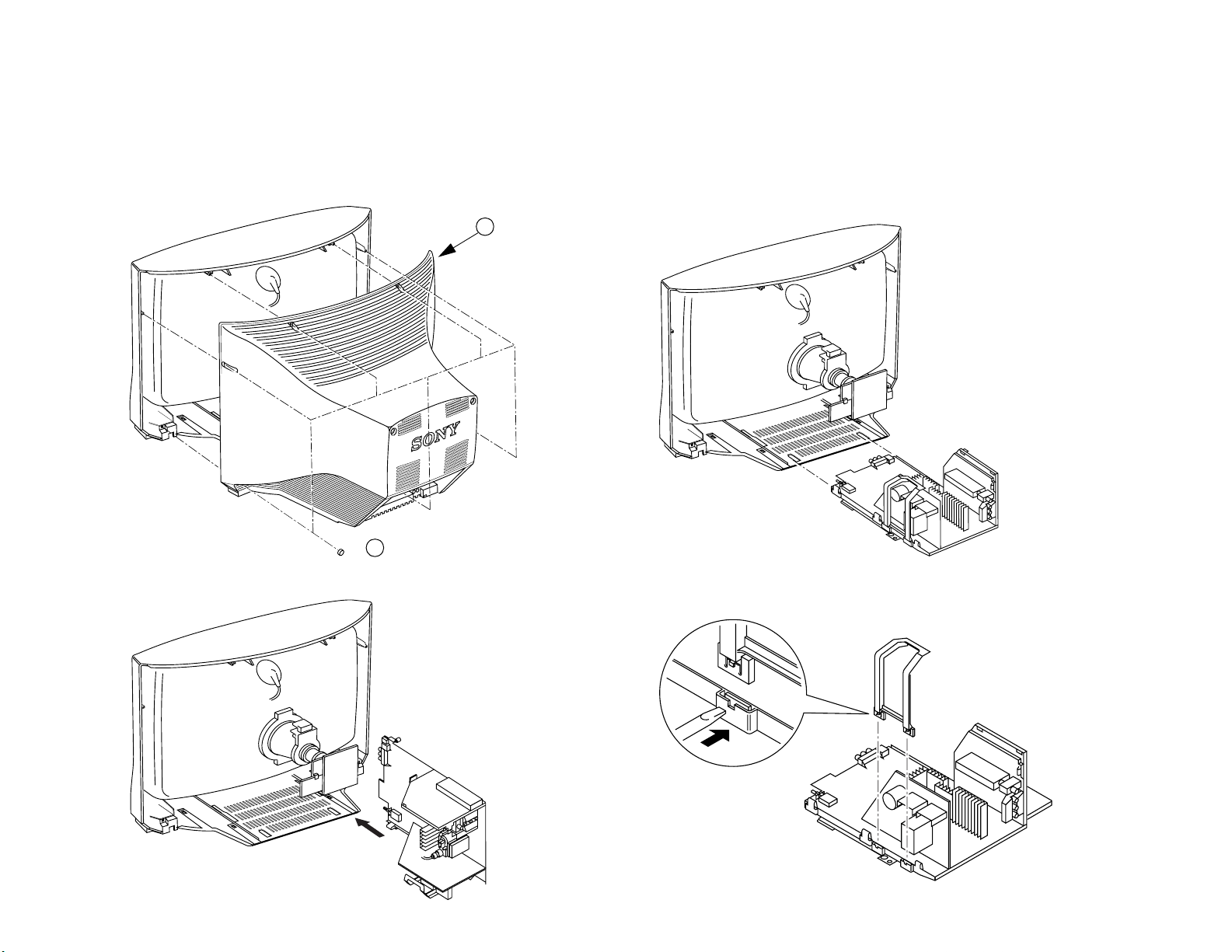
2-1. REAR COVER REMOVAL
2-2. CHASSIS ASSY REMOVAL
2 Rear Cover
1 7 Screws BTV 4x16
2-4. G BOARD REMOVAL 2-3. SERVICE POSITION
To release, push
the claws in the direction of
the arrow as indicated.
KV-28WF3/32WF3
2-5. A BOARD REMOVAL
KV-28WF3/32WF3
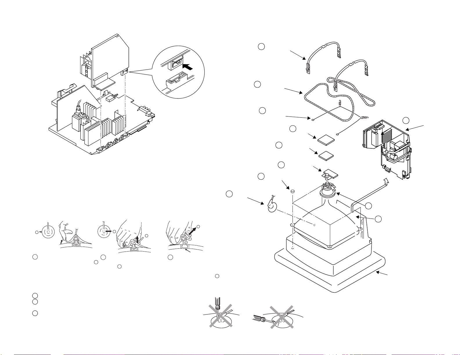
2-6. PICTURE TUBE REMOVAL
Release the clip indicated.
7 Two DGC holders
8 Degaussing coils
9 Spring Extension
2 Chassis assy
3 C board
4 VM Board
18
• REMOVAL OF ANODE-CAP
Note : Short circuit the anod e of the picture tube and the anode cap t o the me t al cha ssis, CRT
shield or carbon paint on the CRT, after removing the anode.
* REMOVING PROCEDURES.
a
1
Turn up one side of the rubber cap in
the direction indicated by the arrow a
b
2 Using a thumb pull up the rubber cap
firmly in the direction indicated by the
arrow b
b
3 When one side of the rubber cap is
separated from the anode button, the
anode-cap can be removed by turning
up the rubber cap and pulling it up in
the direction of the arrow c
• HOW TO HANDLE THE ANODE-CAP
1 To prevent damaging the surface of the anode-cap do not use sharp materia ls.
2 Do not apply too great a pressure on th e rubber, as this may cause damage to the
anode connector.
3 A metal fitting called a shatter hook terminal is fitted inside the rubber cap.
Do not turn the rubber foot over excessively this may cause damage if the shatter
hook sticks out.
c
Anode button
5 Neck assy
10 Four PT screws (M)
1 Anode cap
6 Deflection yolk
11 Picture tube
Cushion
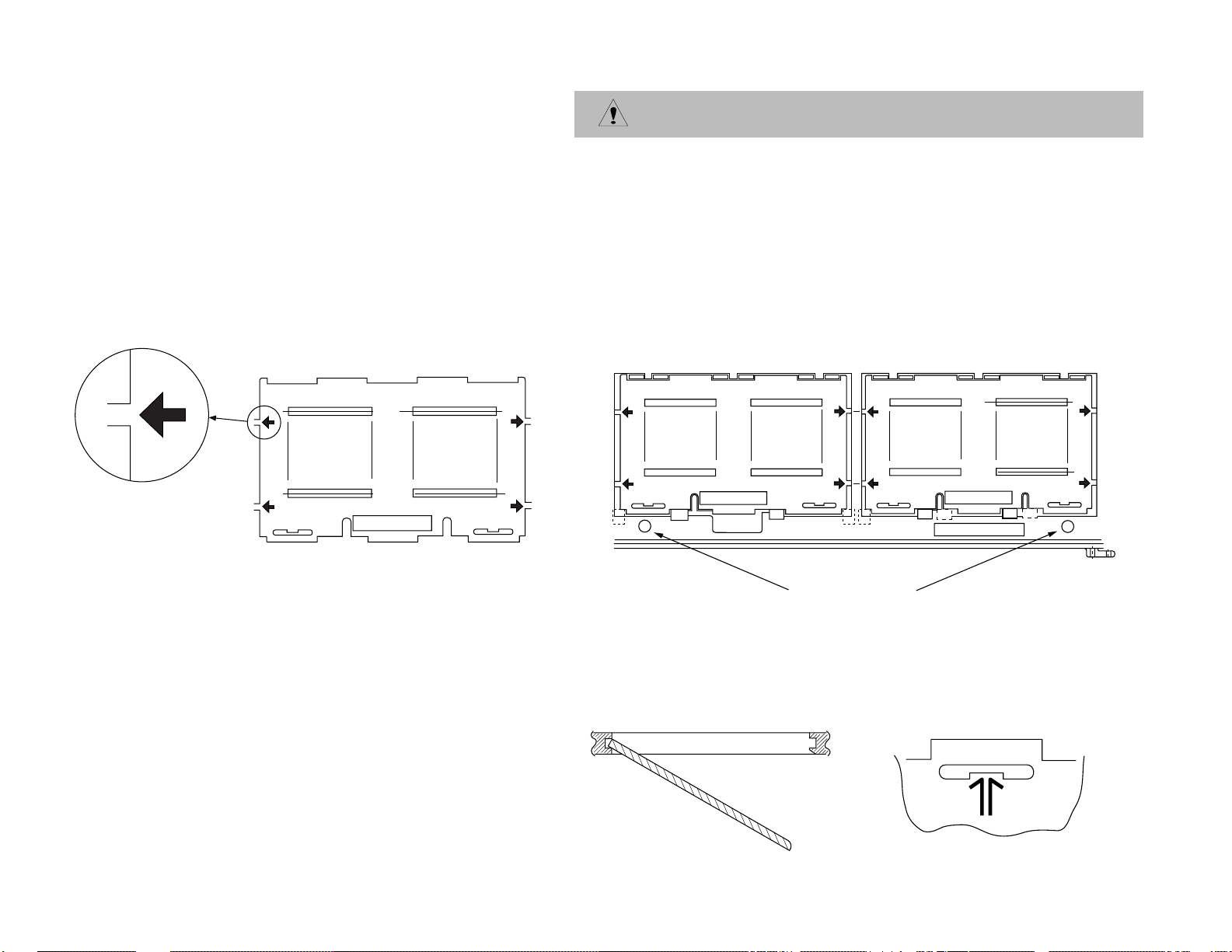
REMOVAL AND REPLACEMENT OF THE MAIN-BRACKET
BOTTOM PLATES.
For safety reasons, on no account should the plates be removed
and not refitted after servicing.
(1) REMOVING THE PLATES
In the event of servicing being required to the solder side of the D Board printed
circuit, the bottom plates fitted to the main chassis bracket require to be removed.
This is performed by cutting the gates with a sharp wire cutter at the locations
shown and indicated by arrows.
Note : There are 5 plates fitted to the main bracket and secured by 4 or 6 gates.
Only remove the necessary plate to gain access to the circuit board.
19
FOR SAFETY REASON THIS
PLATE MUST BE REMOUNTED
AFTER CUTTING AND
TAKING AWAY.
Fig 1
(2) REFITTING THE PLATES
Because the plates differ in size it is important that the correct plates are refitted in their
original location.
The plates are identified by markings A-B-C-D-E on their top side.
1. Identify the plate by locating its marking.
2. Turn the plate over noting where the marking is located.
3. Locate the corresponding marking indicated on the main chassis bracket. See Fig 2.
4. Refit the plate as indicated in Fig 3 with the markings located next to each other.
FOR SAFETY REASON THIS
PLATE MUST BE REMOUNTED
AFTER CUTTING AND
TAKING AWAY.
ATTENTION
D
E
Fig 2
FOR SAFETY REASON THIS
PLATE MUST BE REMOUNTED
AFTER CUTTING AND
TAKING AWAY.
ATTENTION
INDEX MARKING
AT BRACKET FRAME
INSERT FROM
THE BOTTOM
SIDE
Fig 3
MAIN BRACKET
In the event of the plates requiring to be
removed at a later stage, this can be achieved
by inserting a screwdriver in the snap-recess
indicated as in Fig 4 and lifting out.
KV-28WF3/32WF3
Fig 4
KV-28WF3/32WF3
SECTION 3
SET-UP ADJUSTMENTS
• When complete readjustment is necessary or a new
picture tube is installed, carry out the following
adjustments.
• Unless there are specific instructions to th e contrary,
carry out these adjustments with the rated power supply.
• Unless there are specific instructions to th e contrary, set the
controls and switches to the following settings :
Contrast ............... normal
Brightness ............... normal
3-1.BEAM LANDING
Preparation:
1. In order to reduce the influence of geomagnetism on the set’s
picture tube, face it in an easterly or westerly direction.
2. Switch on the set’s power and degauss with the
degausser.
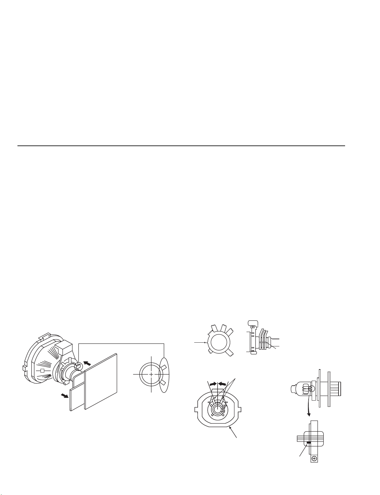
(1) Adjustment of Correction Magnet for Y-Splitting
Axis
1. Input a crosshatch signal from the pattern generator.
2. Set the Picture control to minimum and confirm that the
Brightness control is set to normal.
3. Position the neck assembly as indicated in Fig.3-2.
4. Move the deflection yolk as far forward as is possible.
5. Adjust the upper and lower pin symmetrically by ope ning or
closing the Y-splitting axis correction magnets located on the
neck assembly.
6. Return the deflection yolk to its original position.
Carry out the following adjustments in this order :
3-1. Beam Landin g
3-2. Convergence
3-3. Focus
3-4. White balance
Note : Test equipment required
1. Color bar/pattern gener ator
2. Degausser
3. Vector scope
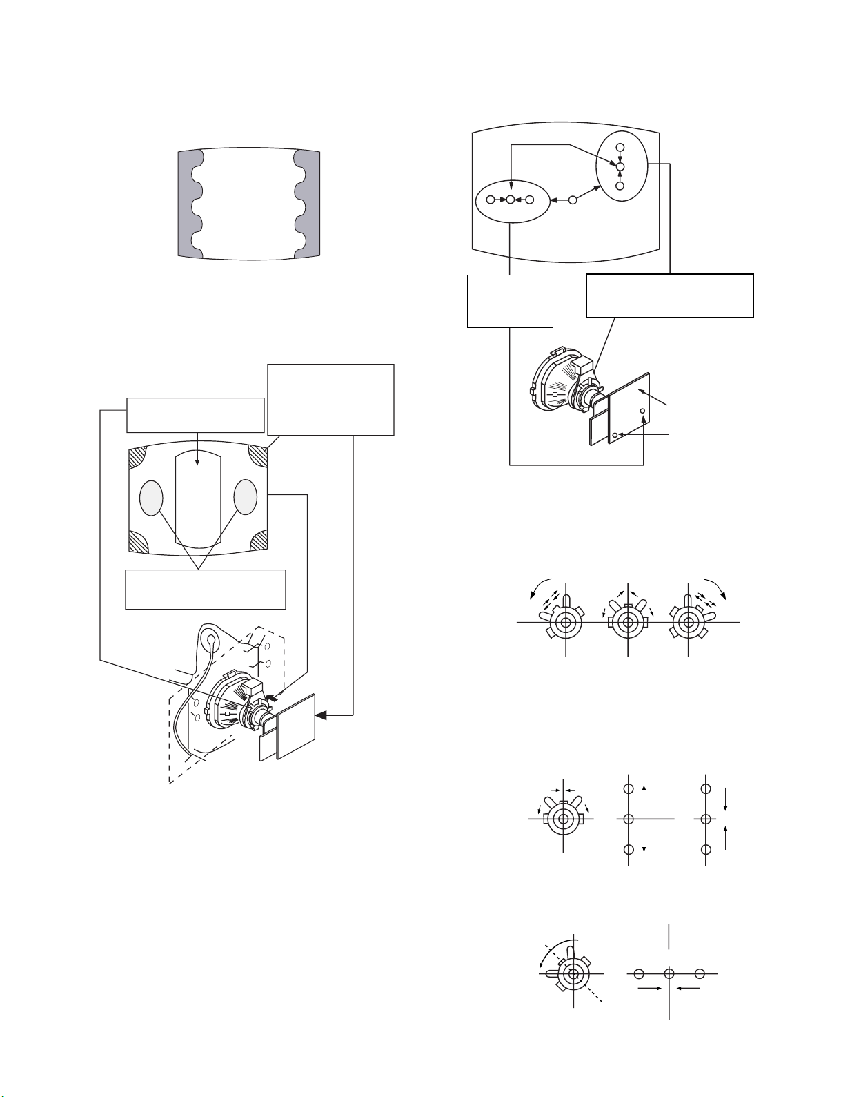
(2) Landing
Note : Before carrying out the following adjustments
adjust the magnets a s indicated below [See Fig.3 -3].
1. Input an all-white signal from the pattern generator.
Maximize the picture setting and adjust the Brightness
setting.
2. Rough-adjust the focus and horizontal convergence.
3. Loosen the deflection yolk screws and align the purity
adjustment knob to its central position. [See Fig.3-1].
4. Switch from the all-white pattern to an all-green pattern.
5. Move the deflection yolk backwards and adjust with the
purity magnet so that the green is at the centre and it aligns
symmetric ally. [See Fig.3-4].
6. Move the deflection yolk forward and adjust so that the
entire screen becomes green.
7. Switch the raster signal to red, then to blue and verify the
landing condition.
8. When the position of the deflection yolk has been dete rm ined ,
fasten the deflection yolk with the screw.
9. If the beam does not land correctly in all the corners of the
screen, use magnets to correct it. [See Fig.3-5].
Y-splitting axis correction magnet
20
Purity
Fig.3-1
Deflection yoke
Align the bottom edge
of the neck assy with
the G3 hole centre.
Fig.3-3
Align Pips
on each
magnet
Neck assy
Fig.3-2
KV-28WF3/32WF3
GREEN
BLUE
RED
Fig. 3-4
Purity control corrects
this area
Deflection yoke positioning
corrects these areas
Disk magnets or
rotatable disk
magnets correct
these areas (a-d)
H.STAT
convergence
Vertical Static Magnet
V.STAT
control
C Board
RV701
Screen (G2)
RV702 (H STAT)
H STAT Convergence
• If the horizontal dots are unable to coincide with the variable
range of the H.STAT convergence, adjust together with the
V.STAT convergence while tracking.
[Adjust the convergence by tilting the V.STAT convergence or
by opening and closing the V.STAT convergence.]
(Open)
(Close)
4. Movement of the red, green and blue dots by tilting the
V.STAT magnet and by opening or closing the V.STAT
magnet.
Fig. 3-5
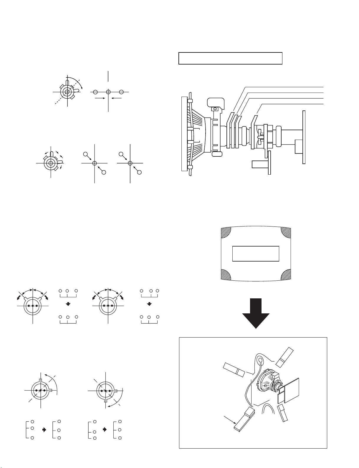
3-2.CONVERGENCE
(1) Screen centre convergence
[Static convergence]
1. Input a dot signal from the pattern generator.
Normalize the picture setting.
2. [Moving horizontally], adjust the H.STAT control so that the
horizontal re d, gre en and b lue dots coinci de at the cent re of the
screen.
3. [Moving vertically], adjust the V.STAT magnet so that the
vertical red, green and blue dots coincide at the c entre of the
screen.
a). By opening or closing the V.S TAT magnet, the red, green and
blue dots move as indicated below.
B
G
R
B
G
R
b). By rotating the V.STAT magnet counter clockwise, the red,
green and blue dots move as indicated below.
B
GR
21
KV-28WF3/32WF3
C < D
C = D C > D C = D
R
G
B
C
D
C
D
R
G
B
R
G
B
R
G
B
VMC correction(A) VMC correction(B)
c). By rotating the V.STAT magnet clockwise, the red, green and
blue dots move in the direction indicated below.
Layout of each control
B
GR
d). By opening or closing the V.STAT magnet, the red, green and
blue dots move in the direction indicated below.
R
G
B
G
B
R
Note : If the blue dot does not coincide with the red and
green points correct the points by using the BMC
[Hexapole] magnet.
e). Correction for HMC [horizontal mis-convergence] and
VMC [vertical mis-convergence] by using the BMC
[Hexapole] magnet.
5. HMC correction by BMC [Hexapole] magnet and movement
of the electr on beam.
Purity magnet
BMC (Hexaploe) magnet
V STAT convergence magnet
Y-splitting axis correction magnet
Fig 3-5
Note : If you ar e unable to adj u st the corner conv ergence
properly, this can be corrected with the use of
permalloys.
a
a-d: screen-corner
convergence defect
b
HMC correction(A) HMC correction(B)
A < B
A = B
RG B
RG B
A > B
A = B
a). VMC correction by BMC [Hexapole] magnet and movement
of the electr on beam.
RGB
RG B
22
b
Permalloy Assy
X-4387-214-1
Convergence adjustment with permalloy
c
d
d
a
c