

Sony KV-27V22 User Manual

SONY
3-859-519-22
Trinitron Color TV
Operating Instructions
KV-27S22
KV-27V22
KV-29PS2
KV-29RS22
KV-29RS22C
KV-29SD2
KV-29V22M
KV-32S22
© 1997 by Sony Corporation
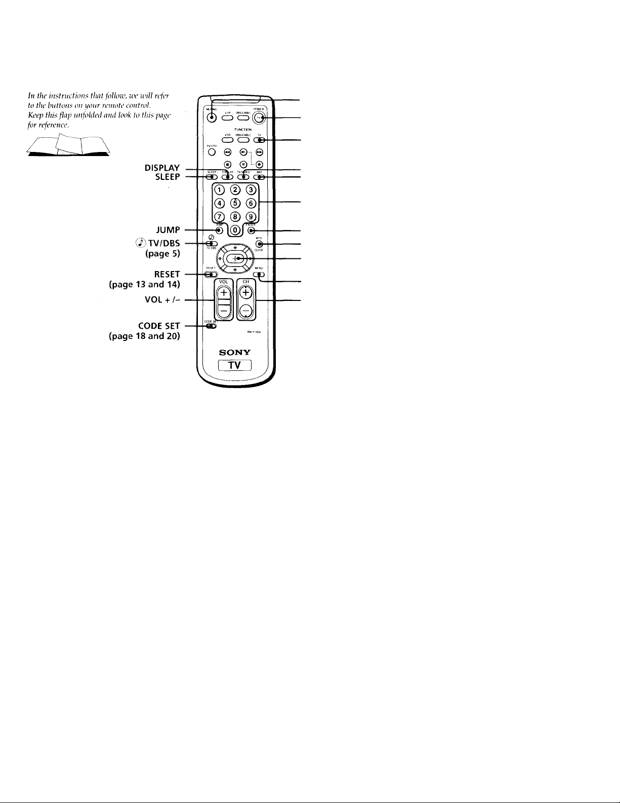
Remote Control
MUTING
TV (POWER)
TV (FUNCTION)
TV/VIDEO
ANT (page 11)
0-9 buttons
ENTER
MTS (page 14)/GUIDE
Select buttons
(page 12)
MENU
CH + /-
Getting to know the buttons on the
remote control
Names of the buttons on the remote control are
presented in different colors to represent the
available functions.
Button color
Transparent..
. Press to select the component
you want to control; e.g.
VTR (VCR), DBS (Direct
Broadcast Satellite)/CABLE,
or TV.
Green
Buttons relevant to power
operations, like turning the
TV, DBS (Direct Broadcast
Satellite)/CABLE, or VTR
(VCR) on or off.
Label color
White...........
TV/VTR (VCR)/DBS (Direct
Broadcast Satellite)/CABLE
operation buttons.
Blue
DBS (Direct Broadcast
Satellite) operation buttons.
For a detailed explanation of most buttons, see
“Watching the TV" on page 10.

WARNING
To prevent fire or shock hazard, do not expose the TV
to rain or moisture.
CAUTION
RISK OF ELECTRIC SHOCK
DO NOT OPEN
ATTENTION
RISQUE DE CHOC ELECTRIQUE,
NE PAS OUVRIR
PRECAUCION
RIESGO DE CHOQUE ELECTRICO
NO ABRIR
CAUTION
When using TV games, computers, and similar products
with your TV, keep the brightness and contrast
functions at low settings. If a fixed (non'moving)
pattern is left on the screen for long periods of time at
a high brightness or contrast setting, the image can be
permanently imprinted onto the screen. Continuously
watching the same program can cause the imprint of
station logos onto the TV screen. These types of
imprints are not covered by your warranty because
they are the result of misuse.
Note on Caption Vision
This television receiver provides display of television
closed captioning in accordance with §15.119 of the
FCC rules.
Note on cleaning the TV
CAUTION. TO RtOUCt THE RISK OF ELECTRIC SHOCK,
DO NOT REMOVE COVER (OR BACK).
NO USER-SERVICEABLE PARTS INSIDE.
REFER SERVICING TO QUALIFIED SERVICE PERSONNEL.
This symbol is intended to alert the user to
the presence of uninsulated "dangerous
A
voltage" within the product's enclosure that
may be of sufficient magnitude to constitute
a risk of electric shock to persons.
This symbol is intended to alert the user to
the presence of important operating and
maintenance (servicing) instructions in the
literature accompanying the appliance.
CAUTION
TO PREVENT ELECTRIC SHOCK, DO NOT USE THIS
POLARIZED AC PLUG WITH AN EXTENSION CORD,
RECEPTACLE, OR OTHER OUTLET UNLESS THE BLADES CAN
BE FUaV INSERTED TO PREVENT BLADE EXPOSURE.
Clean the TV with a soft dry cloth. Never use strong
solvents such as thinner or benzine, which might
damage'the finish of the cabinet.
Note to CATV system installer
This reminder is provided to call the CATV system
installer's attention to Article 820-40 of the NEC that
provides guidelines for proper grounding and, in
particular, specifies that the cable ground shall be
connected to the grounding system of the building, as
dose to the point of cable entry as practical.
Use of this television receiver for other than private
viewing of programs broadcast on UHF or VHF or
transmitted by cable companies for the use of the
general public may require authorization from the
broadcaster/cable company and/or program owner.
NOTIFICATION
This equipment has been tested and found to comply
with the limits for a Class B digital device pursuant to
Part 15 of the FCC Rules. These limits are designed to
provide reasonable protection against harmful
interference in a residential installation. This
equipment generates, uses, and can radiate radio
frequency energy and, if not installed and used in
accordance with the instructions, may cause harmful
interference with radio communications. However,
there is no guarantee that interference will not occur
in a particular installation. If this equipment does
cause harmful interference to radio or television
reception, which can be determined by turning the
equipment off and on, the user is encouraged to try to
correct the interference by one or more of the
following measures:
• Reorient or relocate the receiving antennas.
• Increase the separation between the equipment and
receiver.
• Connect the equipment into an outlet on a circuit
different from that to which the receiver is
connected.
• Consult the dealer or an experienced radio/TV
technician for help.
You are cautioned that any changes or
modifications not expressly approved in this
manual could void your authority to operate this
equipment.
This document is for the remote control RM-Y135A.
MODELS: KV-27S22, 27V22, 29PS2, 29RS22, 29RS22C,
29SD2, 29V22M, 32S22
Welcome!
fiMm Precautions
IVH Using This Manual
Thank you for purchasing the Sony Trinitron®
Color TV. This manual is written for the models
listed below. Before reading, check the model
number on the rear of your TV.
Model KV-27S22 is used for illustration purposes.
The screens displayed are for model KV-29V22M.
Differences in operation features are indicated in
the text; for example, "KV-27S22 only".
is
V
Model
Number / 4^
KV-27S22
KV-29PS2
KV-29RS22C
KV-29SD2 1
KV-29V22M
KV.32S22 1
• • • •
•
^//
•
•
• •
■■ *
i
^ / i
•
•
■ -, ^
Safety
• Operate the TV only on 120 V AC
(except KV-29RS22C).
• Operate the TV only on 220 V AC
(KV-29RS22C only).
• The plug is designed, for safety purposes,
to fit in the wall outlet only one way. If you
are unable to insert the plug fully into the
outlet, contact your dealer
(except KV-29RS22C).
• If any liquid or solid object should fall inside
the cabinet, unplug the TV immediately and
have it checked by qualified persormel before
operating it further.
• If you will not be using the TV for several
days, disconnect power by pulling the plug
itself. Never pull on the cord.
For details concerning safety precautions, see the
supplied leaflet "IMPORTANT SAFEGUARDS".
Installing
• To prevent internal heat build-up, do not
block the ventilation openings.
• Do not install the TV in a hot or humid
place, or in a place subject to excessive dust
or mechanical vibration.
This manual is divided into four major
sections. We recommend that you carefully
review the contents of each section in the
order provided to ensure that you fully
understand the operation of your new TV.
1 Connecting and Installing the TV.
This section will guide you through your
initial set up. It will show you how to
connect your new components, connect to
your antenna or cable, and connect any
accessories.
2 Basic Set Up.
This section will teach you the basic skills
needed to operate your new TV. It will
show you how to operate special functions
of the remote control.
3 Using your New TV.
This section will show you how to begin
using your new TV. It will show you how
to use the AUTO SET UP feature, and how
to use your remote control's features.
4 Adjusting your Set Up (menus).
This section will teach you how to access
on-screen menus and adjust your TV's
settings.
Instructions in this manual are written for the remote
control Similar controls may be found on the TV console.
fM i Connecting and Installing the TV
Connector Types
You may find it necessary to use some of the
following connector types during set up.
Coaxial Cable
Standard TV Cable and Antenna connector
Plug Type
cO
Screw-on Type
Press onto connection
( (lift FMl Screw onto connection
S Video Cable
High quality Video connector for enhanced
picture quality
{(3 —*■ ©)) Align guides and
press onto connection
Audio/Video Cable
Conventional Audio/Video cable
Press onto connection
Yellow - Video
White - Audio (Left)
Red - Audio (Right)
Making Connections
For best picture quality, a cable TV system or
outdoor antenna is recommended.
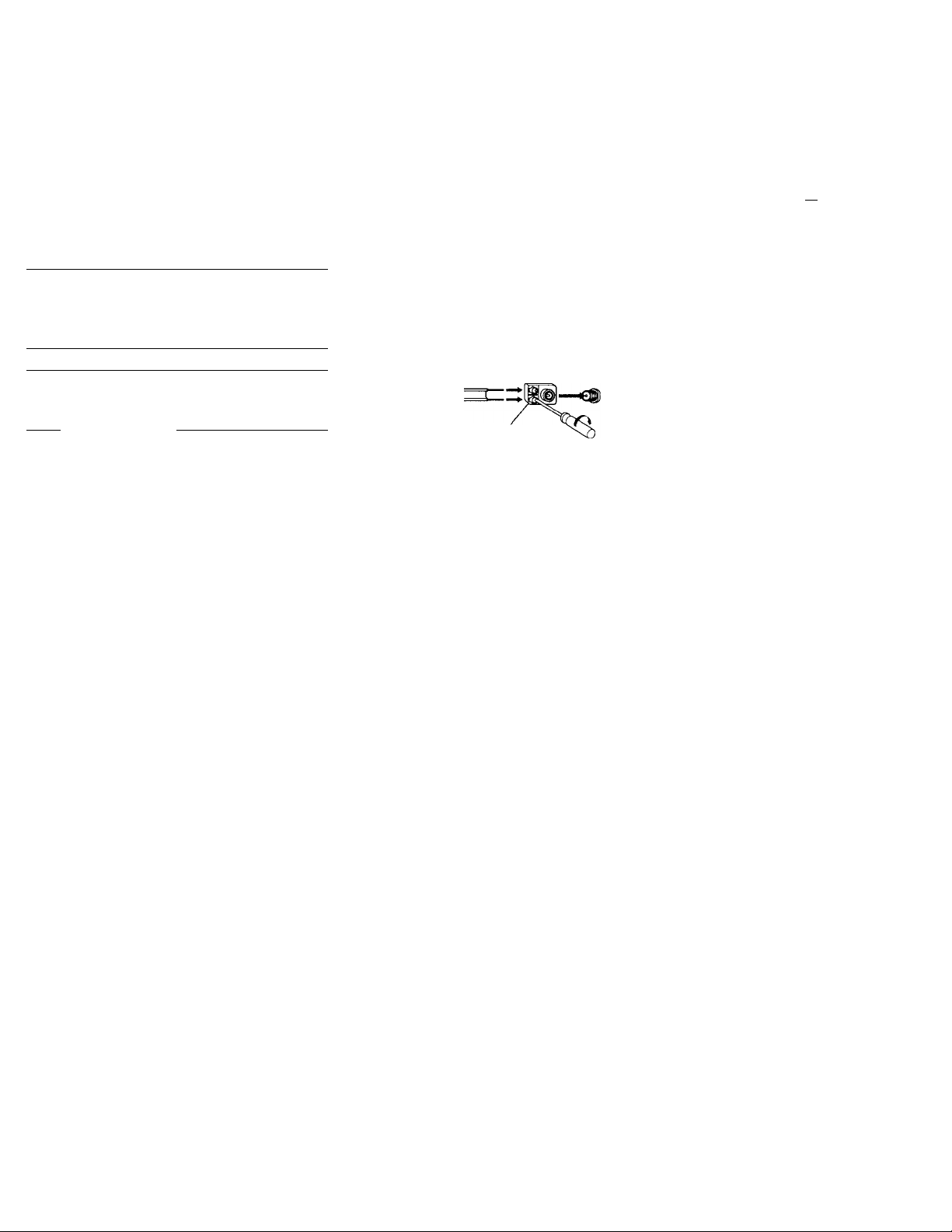
Connecting directly to cable or an antenna
The connection you choose will depend on
the cable found in your home. Newer homes
will be equipped with standard coaxial cable
(see A); older homes will probably have 300ohm twin lead cable (see B); still other homes
may contain both (see C).
B
• VHP only
or
• VHF/UHF
or
• Cable
• VHF only
or
• UHP only
or
• VHF/UHF
75-ohm coaxial cable
VHP
and
UHF
300-ohm twin lead cable
75-ohm (Rear of TV)
coaxial cable VHF/UHF
=dH]
300-ohm twin
lead cable
Antenna connector
R
EAC-66 U/V mixer
(not supplied)
(Rear of TV)
(Rear of TV)
VHF/UHF
VHF/UHF
Cable or antenna
This is the most simple cormection. Cormectioi
is made directly from the cable or antenna to
the TV.
Cable
(Rear of TV) VHF/UHF
=tTT—
Connecting a cable box
Some pay cable TV systems use scrambled or
encoded signals that require a cable box* to
view all channels.
Cable
1 r
D D *c
IN
^ ^ OUT
* Your Sony remote control can be programmed
to operate your cable box (see page 18).
Note:
• If you will be controlling all channel selections
through your cable box, you should consider
using the CHANNEL FIX feature discussed on
page 16.
(Rear of TV) VHF/UHF
_ Cable box
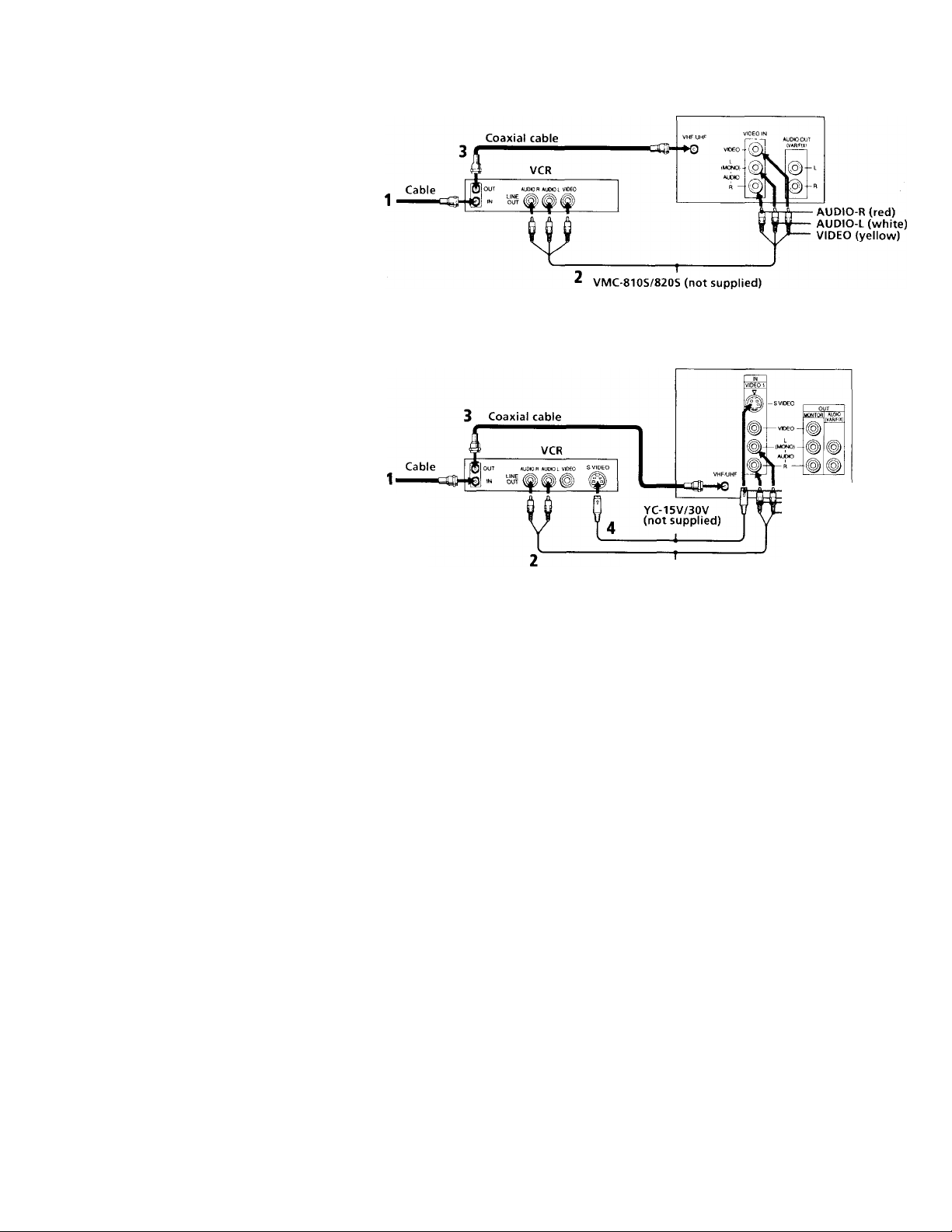
Connecting an antennci/cable TV
system with a VCR
1 Attach the coaxial connector from your
cable or antenna to IN on your VCR.
2 Using AUDIO/VIDEO connectors,
connect AUDIO and VIDEO OUT on your
VCR to AUDIO and VIDEO IN on your TV
(Yellow-VIDEO, White-AUDIO Left, RedAUDIO Right).*
3 Using a coaxial connector, connect OUT on
your VCR to VHF/UHF on your TV.
Connecting to an S Video equipped VCR (for optimum picture quality)
• KV-27V22, 29V22M only
1 Attach the coaxial connector from your
cable or antenna to IN on your VCR.
2 Using AUDIO connectors, connect AUDIO
OUT on your VCR to AUDIO IN on your
TV (White-AUDIO Left, Red-AUDIO Right).*
3 Using a coaxial connector, connect OUT on
your VCR to VHF/UHF on your TV.
4 Using an S VIDEO connector, connect
S VIDEO on your VCR to S VIDEO on
your TV.
• If you are connecting a monaural VCR, connect orJy
the single audio output to the left input on your TVi
Note on DVD Connection:
• For the best picture quality, connect the DVD player directly to the TV.
Refer to your DVD manual for detailed connection information.
Disconnect all power sources before making any connections.
(Rear of TV)
(Rear of TV)
S VIDEO
AUDIO-R (red)
AUDIO-L (white)
RK-74A (not supplied)

IB Connecting and Installing the TV (continued)
Connecting a VCR and TV with a cable box
1 Connect the single (input) jack of the Splitter to
your incoming cable connection, and connect the
other two (output) jacks (using coaxial cable) to
IN on your cable box and VHF/UHF on your
TV.
2 Using a coaxial connector, connect OUT on
your cable box to IN on your VCR.
3 Using AUDIO/VIDEO connectors, connect
AUDIO and VIDEO OUT on your VCR to
AUDIO and VIDEO EM on your TV (YeUowVIDEO, White-AUDIO Left, Red-AUDIO
Right).
Connecting to an S Video equipped
VCR with a cable box
(for optimum picture quality)
• KV-27V22, 29V22M only
1 -2 Perform as described above.
3 Using AUDIO connectors, connect AUDIO
OUT on your VCR to AUDIO IN on your TV
(White-AUDIO Left, Red-AUDIO Right).
4 Using an S Video connector, connect S VIDEO
on your VCR to S VIDEO on your TV.
Note:
• To view scrambled channels through your cable box, select
VIDEO 1 by pressing TV /VIDEO on the remote control.
Coaxial cable
Splitter
(not supplied)
Coaxial cable
Splitter
(not supplied)
Disconnect all power sources before making any connection
(Rear of TV)
Cable box
(Rear of TV)
t©
YC-15V/30V
(not supplied)
-----------1----------
RK-74A (not supplied)
Cable box
-r
AUDIO-R (red)
AUDIO-L(whit
VIDEO (yellow
S VIDEO
AUDIO-R (red)
AUDIO-L (white)

Connecting a DBS (Direct Broadcast
Satellite) receiver
1 Connect the cable from your satellite antenna
to your DBS receiver.
2 Attach the coaxial connector from your cable
or antenna to VHF/UHF on your TV.
3 Using AUDIO /VIDEO connectors, connect
AUDIO and VIDEO OUT on your DBS receiver
to AUDIO and VIDEO IN on your TV.
Disconnect all power sources before making any connections
For the highest picture quality, use S VIDEO instead of the
yellow AUDKWIDEO cable. (KV-27V22,29V22M only)
See your DBS manual for more information.
DBS receiver
»UDOR AUCHQL VOFO SVIDEO IN
2
VHF/UHF
lojouT
VHFUIHF
(Rear of TV)
lOEOlN
r
-----------
^0 vKieo -
(MCNO)-H
AUOC
R —' 1^-
1 AUDIO OUT
(VAfVFlX
-L
-R
. AUDIO-R (red)
AUDIO-L (white)
VIDEO (yellow)
Connecting a DBS (Direct Broadcast Satellite) receiver and a VCR
1 Connect the cable from your satellite
antenna to your DBS receiver.
2 Attach the coaxial connector from your cable
or antenna to VHF/UHF-IN on your VCR.
3 Using a coaxial connector, connect VHF / UHF-
OUT on your VCR to VHF/UHF on your TV.
4 Using AUDIO/VIDEO connectors, connect
AUDIO and VIDEO OUT on your DBS receiver
to AUDIO and VIDEO IN on your VCR.
5 Using AUDIO/VIDEO connectors, connect
AUDIO and VIDEO OUT on your VCR to
AUDIO and VIDEO IN on your TV.
Note:
• To view input from the DBS or VCR, select VIDEO 1
by pressing TV/VIDEO on the remote control.
DBS receiver
VMC-810S/820S (not supplied)
-I
VIDEO (yellow)
AUDIO-L (white)
AUDIO-R (red)
-----------------1-------------
VMC-810S/820S (not supplied)
VMC-810S/820S (not supplied)
Connecting and Installing the TV (continued)
Connecting an audio system
For greater viewing pleasure, integrate your
home stereo into the system.
1 Using AUDIO connectors, connect AUDIO
OUT on your TV to one of the unused Line
inputs (e.g. Tape-2, etc.) on your stereo
(White-AUDIO Left, Red-AUDIO Right).
2 Set your stereo to the chosen Line input
and refer to page 14 of this manual for
additional audio setup instructions.
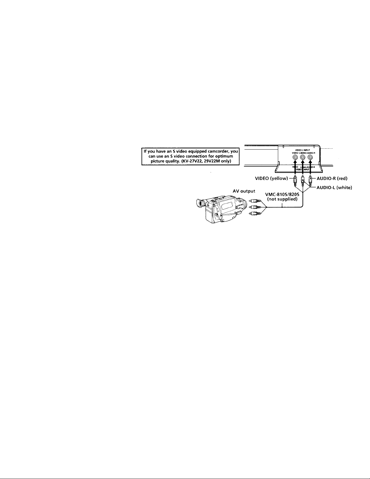
Connecting a camcorder
• KV-27V22, 29V22M only
This connection is convenient for viewing a
picture directly from your camcorder.
Using AUDIO/VIDEO connectors, connect
AUDIO and VIDEO OUT on your camcorder
to AUDIO and VIDEO IN on the front panel
of your TV (Yellow-VIDEO, White-AUDIO
Left, Red-AUDIO Right).
VHPAJHF
Q voeo
(Rear of TV)
(MC^ 4 (vO J
ALlbtO
Disconnect all power sources before making any connection:
1
AUDIO-L (white)
AUDIO-R (red)
RK-74A
(not supplied)
Line
input
rill.
Note:
• If you are connecting a monoaural camcorder,
connect only the single audio output to the left
input on your TV.
 Loading...