

Sony KV-27EXR25 Service Manual
PHOTOFACT,
Technical Service Data
INDEX
Adjustment and Alignment Tools
Convergence Adjustments
GridTrace
Important Parts Information
Miscellaneous Adjustments
PartsList ................. 9,10,11
Photos
!
Troubleshooting Quick-Checks
PIP Adjustments
Placement Chart
Safety Precautions
Safety Related Adjustments
Schematics
Terminal Guides and Notes
Test Equipment
Troubleshooting
Tuner Terminal Guide
Tuner Voltage Chart
Location Guide
ABoard ....................
GBoard ....................
PBoard-TopBoard
UlBoard
...................
ABoard ..................
CBoard ....................
Cabinet - Rear View
CRT Neck Assembly
GBoard ....................
HBoard ....................
PBoard-BottomBoard .....
PBoard-TopBoard
Ul
Board
U2Board .................
ABoard ....................
CBoard ....................
CRT
Control
D/A Converter
MTS Decoder
PIP
Power Supply
Television
.................
..................
.................
.......................
...................... .
..........................
...................
...................
...................
...........
...........
........
...............
................
...............
................
.............
...............
....
..........
........
.........
..........
.........
........
..9
.7,8
.7,8
.7,8
.4,9
.8,9
.8
.9
.8
.9
.9
10
.9
.9
.8
.7
.9
.5
.2
.3
.4
.2
.7
SONY
1
6
8
6
1
6
6
1
6
2
4
1
1
6
6
Model
l
l
W-27EXR25
(Chassis SCC-D50F-A)
Complete coverage
for servicing a television receiver...
Schematics
Component
locations
Coverage includes this additional model and chassis:
MODEL
KV-27EXR20
l
Parts lists
l
Troubleshooting
guide
CHASSIS
SCC-DSOE-A
For Supplier Address,
See PHOTOFACT Annual Index
HOWARD
DECEMBER 1991 SET 2910
W.
SAMS & COMPANY
TROUBLESHOOTING
POWER SUPPLY
Check AC Fuse F60 1.
If
F60
1 is open:
Check Bridge Rectifier Diodes (D601, and D602), Resistor
(R601), Capacitors. C601, C603 thru C606, Electrolytics C607,
and C650, Power Converter IC (IC65
(T604).
Apply 120V and check for
If
17.OV
is missing:
Check Line Filters (T601, T602), Power Transformer (T604),
Capacitors C608, C609, Electrolytic C610, and
If
17.OV
is present, check for
If
15OV*
is missing:
Check the voltages, waveforms, and components associated
with Power Relay (RY601), and Relay Driver Transistor
(Q601), and D601.
Note: The set may be in shutdown. Refer to the “High Voltage
Shutdown” section of this Troubleshooting guide.
If
15OV*
is present at the (+) lead of D601, check for the proper wa-
veform at pin 1 of IC65 1.
If the waveform is missing:
Check the voltages, waveforms, and components associated
with IC65 1, Transfer IC (IC652), Converter Transformer
(T651), and Soft Start Transistor
If the proper waveform is present at
Check the voltages, waveforms, and components associated
with T6.5 1.
* Taken from isolated ground.
17.OV
at the (+) lead of D602.
15OV*
l),
at the (+)
(4612).
pin
1 of IC65 1:
and Power Transformer
D602.
lead
of D601.
HORIZONTAL
Determine if the TV is in shutdown:
Refer to the “High Voltage Shutdown” section of this
Troubleshooting guide.
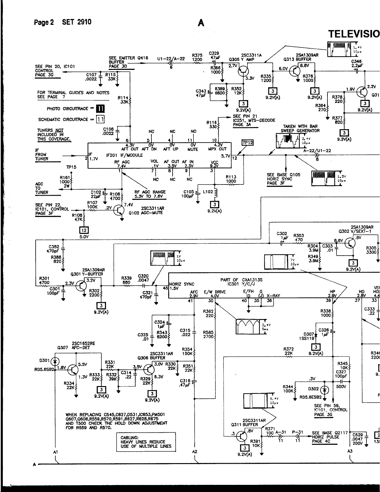
If the TV is not in shutdown, inject a horizontal signal at the base of
the Horizontal Output Transistor
If horizontal deflection is now present:
Check the voltages, waveforms, and components associated
with pins
Horizontal Drive Transistor (Q501).
If there is no horizontal sweep:
Check the voltages, waveforms, and components associated
with
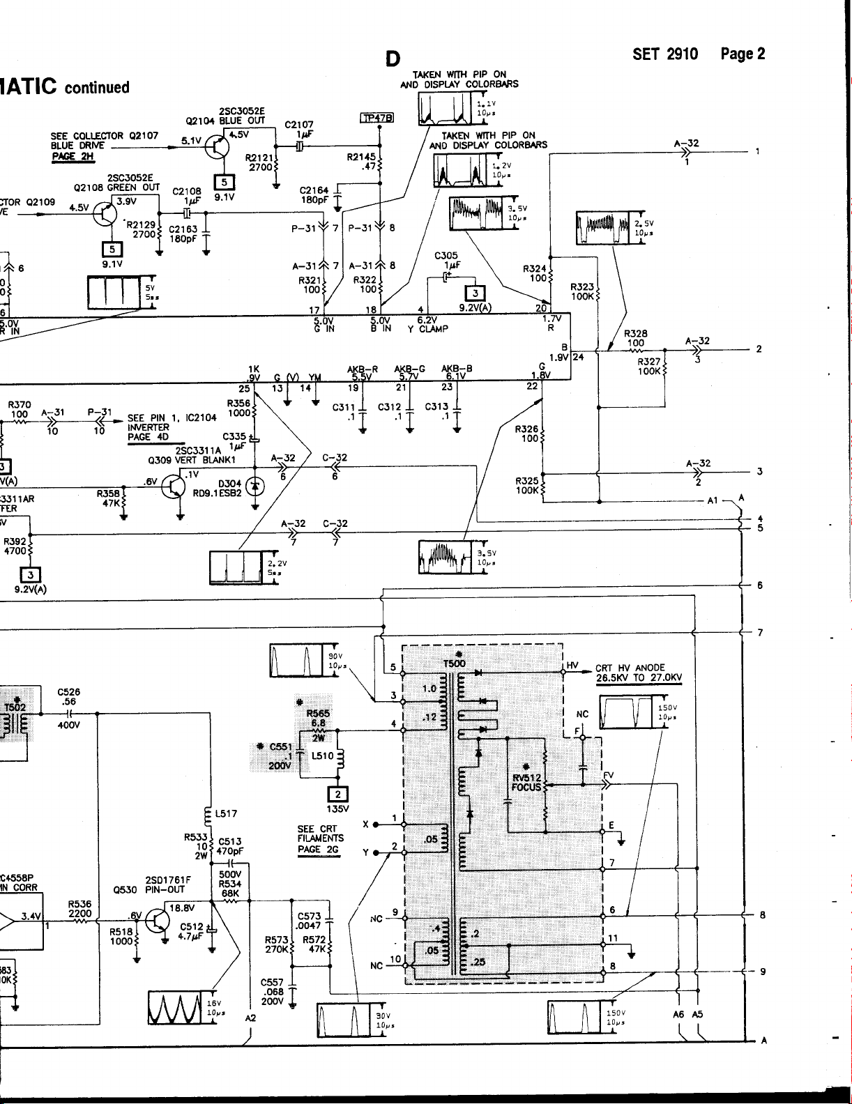
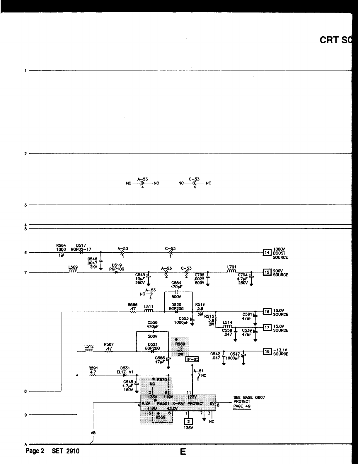
check components associated with Diodes D5 17, D5 19, D520,
D521, and D531 for defects.
The high voltage rectifier is part of T500 and if defective will effect
the performance of the horizontal circuits.
If the horizontal oscillator is off frequency:
Check the voltages, waveforms, and components associated
with AFC-DET Transistor (Q307), and Buffer Transistor
(Q3W.
Horizontal linearity or
tors C506, C507, and C509 beiig defective.
37,39,41,
4502,
and Horizontal Output Transformer
foldover
(4502).
and 45 of Y/C/J IC (IC301), and
(T500),
problems may be caused by Capaci-
and
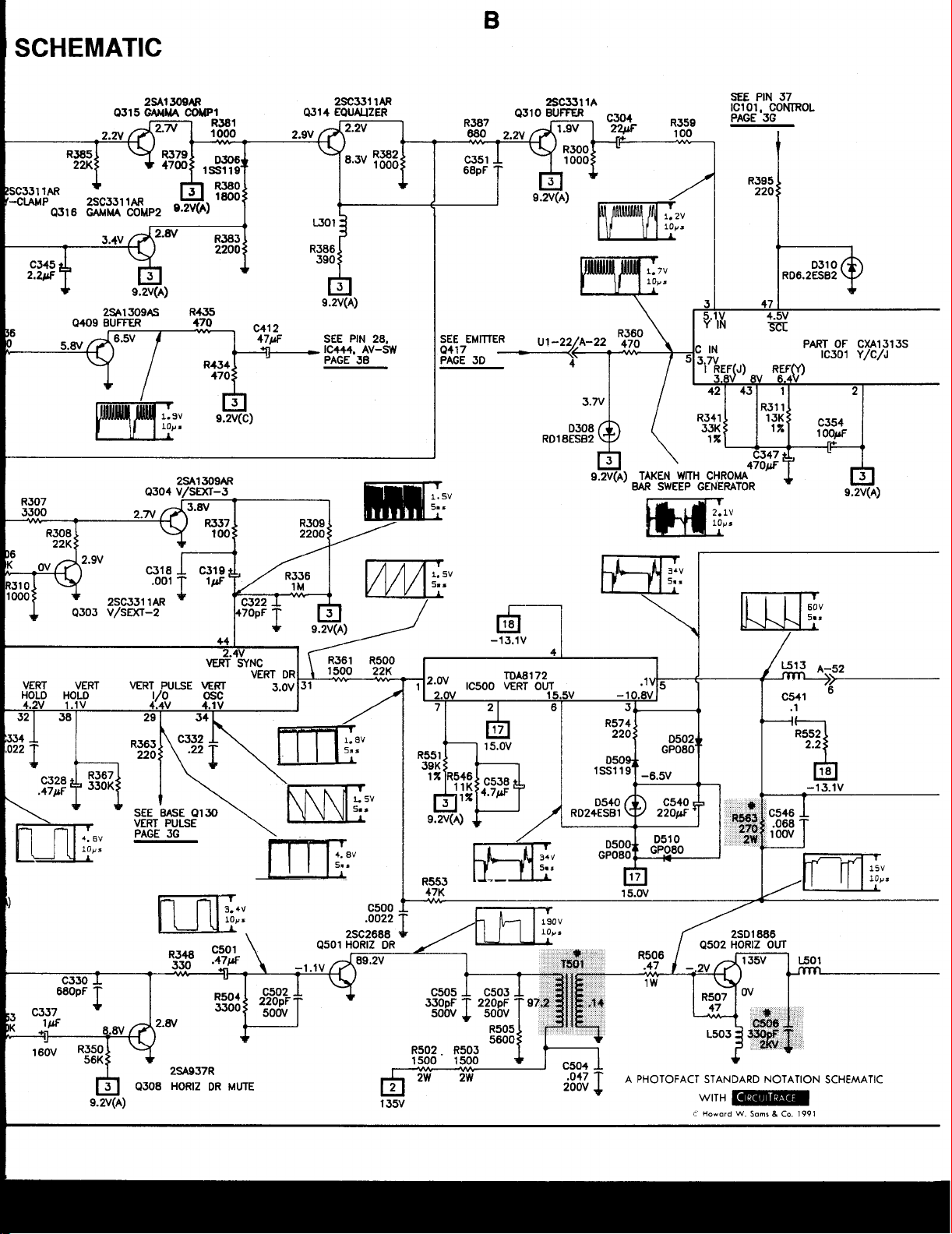
VERTICAL
Inject a vertical drive signal at pin 3 1 of Y/C/J IC (IC301).
If vertical deflection is now present:
Check the voltages, waveforms, and components associated
with pins 29
thrn 34,38,
and 44 of IC301.
HIGH VOLTAGE SHUTDOWN
The
high voltage is monitored by Diode D531, rectifying pulses
from the Horizontal Output Transformer (T500). Should the high
,voltage increase, the rectified voltage at the cathode of Diode D531
will also increase, This will cause the voltage at pin 8 of Protect
Module (PM501) to increase and turn on Protect Transistors (Q607,
4608)
which causes Relay Drive Transistor (4601) to turn off and
remove power from the set.
To troubleshoot, remove Resistor R629 fom the circuit. Use a
for AC power. Start at 90VAC and increase as
and repair the defect. Return R629 to the circuit.
Note: Care should be taken in defeating the high voltage shutdown
circuit, as this may cause excessive X-radiation and damage the
CRT,
TSOO,
and associated components. Monitor the high voltage
and troubleshoot.
necessary
variac
to locate
If there is still no vertical deflection:
Check the voltages, waveforms, and components associated
with Vert Out IC
Vertical linearity or
ion, vertical feedback and
Check the voltages, waveforms, and components associated
with Pin Correction IC (IC531) and Pin Out Transistor (4530).
Also check Electrolytics C328, C538, C540, C562, C563, and
C566 for defects.
(ICSOO).
foldover
bias
problems may be caused by pincush-
circuits:
IF-AGC
Inject a video signal at the IF input and check for video on the CRT.
If video is present:
Check the tuner, tuner control, and tuner AFC circuits.
TROUBLESHOOTING
continued
If there is no video on the CRT, check for a video waveform at
TP12.
If video is present at TP12:
Refer to the “Video” section of this Troubleshooting guide.
If there is no
Check the voltages, waveforms, and components associated
with IF Module
A defective AGC circuit can cause an overloaded picture, excessive
snow or loss of audio and video.
See the AGC Voltage Chart for AGC voltages with signal.
video
at TP12:
(IF201),
and AGC Mute Transistor
AGC Voltage Chart
pm 1 5.3v
(Q102).
IF201
SYNC
If there is no vertical or horizontal sync:
Check the voltages, waveforms, and components associated
with Y Buffer Transistor (4301).
If there is no vertical sync:
Check the voltages, waveforms, and components associated
with pins 38, and 44 of Y/C/J IC
(Q302), V/Sext
(Q3W.
If there is no horizontal sync:
Check the voltages, waveforms, and components associated
with pins 41, and 45 of
2 Transitor
IC301.
(IC301), V/Sext
(Q303),
and
V/Sext
1 Transistor
3 Transistor
VIDEO
Check the voltages, waveforms, and components associated
with pins
Transistors (43
and Equalizer Transistor (43
and Gamma Comp 2 Transistor (4316).
If brightness is inadequate or
Check the voltages, waveforms, and components associated
with pin 5 of v901.
3,4,8,26,
lO,Q3 13),
and 27 of Y/C/J IC
Gamma Comp 1 Transistor (43
14).
camrot
be
(IC301),
Y Clamp Transistor (43
controll&
Buffer
15),
17),
CHROMA
Check for a chroma waveform at pm 5 of Y/C/J IC (X301).
If the waveform is missing:
Check the voltages, waveforms, and components associated
with Buffer Transistor
of Comb Filter (CM1301).
If chroma waveform is present at pin 5 of
er waveforms at pins
If these waveforms are missing:
Check the voltages, waveforms, and components associated
with pins
Check the
If the proper wavforms are present at pins
Refer to the “Raster” section of this Troubleshooting guide.
5,6,7,19
3.58MHz
(Q417),
C-Switch IC
20,22,24
of
IC301.
thru 25 of
oscillator at pin 7 of
IC301.
(IC403),
IC30
1, cheek for the
IC301.
20,22,24
of
and pin 4
pmp
IC301:
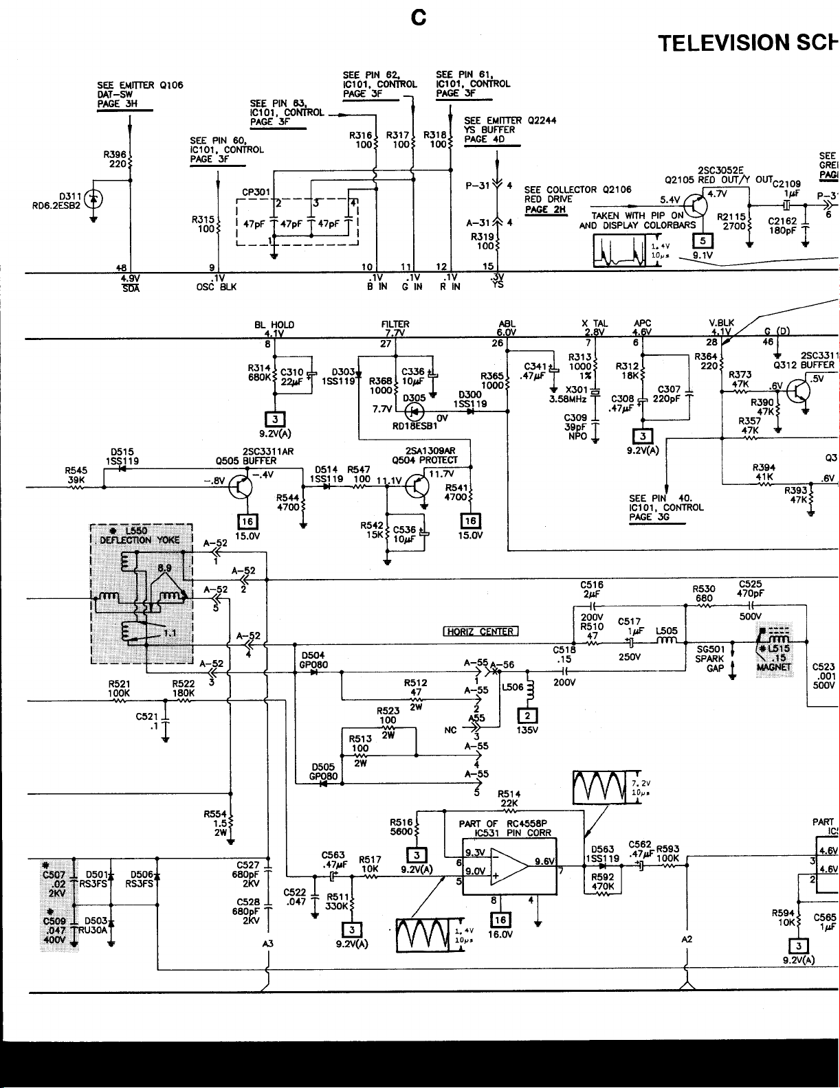
RASTER
Check the CRT and CRT voltages. Cheek the voltages, waveforms,
and components associated with Buffer Transistor
Transistor
If there is no Red:
(Q710),
and SW 2 Transistor (4712).
(Q711),
SW 1
Inject a signal at
If video is present:
Refer to the
If there is no video on the CRT, check for a video waveform at pin 6
of Comb Filter (CM1301).
If video is missing at pm 6 of CM1301:
Check the voltages, waveforms, and components associated
with Buffer Transistors (4409,
(IC444),
If video is present at pin 6 of CM1301, check for a video waveform
at the emitter of Y Amp Transistor (4305).
If the video is missing:
Check the voltages, waveforms, and components associated
with 4305, Buffer Transistor
If the waveform is present at the emitter of 4305:
TP12,
and check for video on the CRT
“IF-AGC”
and CM1301.
section of this
Q410),
(Q416),
Troubleshooting
and AV-Switch IC
and Y Switch IC
guide.
(IC402).
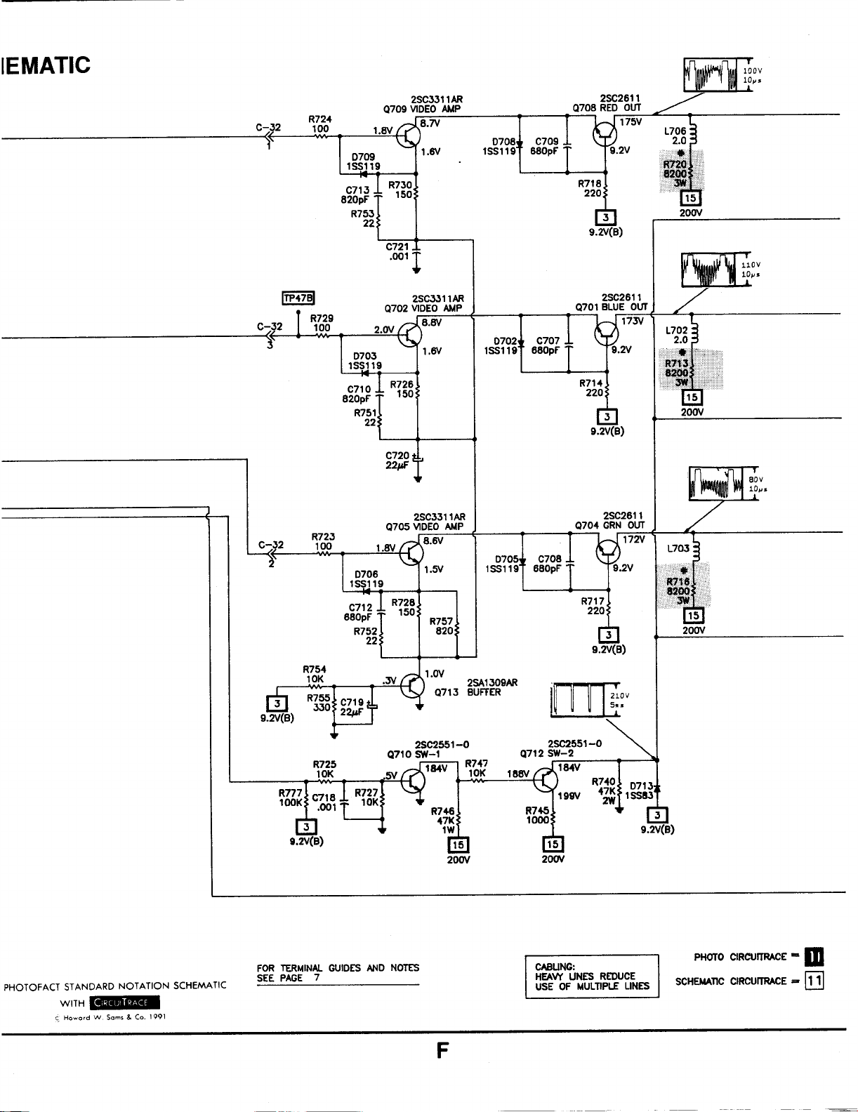
Cheek the voltages, waveforms, and components associated
with pin 20 of Y/C/J IC
Video Amp Transistor
(Q707,Q7
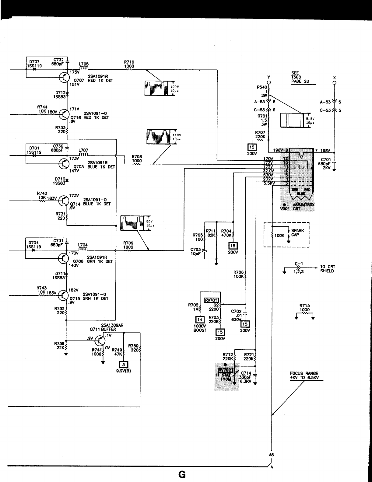
If there is no Green:
Check the voltages, waveforms, and components associated
with pin 22 of
Amp Transistor
47 15).
If there is no Blue:
Check the voltages, waveforms, and components associated
with pm 24 of
Amp Transistor
47 14).
If the raster has a keystone shape:
Check the Deflection Yoke
16).
IC301,
IC301,
(IC301),
(Q709),
Green Output Transistor
(Q705),
and Green 1K Det Transistors (4706,
Blue Output Transistor
(Q702),
and Blue 1K Det Transistors
Red Output Transistor
and Red 1K Det Transistors
(Q701),
(L550).
(Q704),
(4708).
Video
Video
(4703,
SET 2910 Page 1
TROUBLESHOOTING
If the raster has height or width problems:
Refer to “Vertical”, “Horizontal”, and “Power Supply” sections
of this Troubleshooting guide.
AUDIO
Select an
pins 1 and 2 of MTS Decode IC (IC25 1).
If there is no audio:
If audio waveforms are present at pins 1 and 2 of IC251, cheek for
audio waveforms at pins 1 and 5 of Audio Amp IC (IC405).
If audio waveforms are missing:
If audio waveforms are present at pins 1 and 5 of IC405:
active TV channel and check for an audio waveforms at
Check the voltages, waveforms, and components associated
with IC25 1, and pin 10 of IF Module (IF201).
Check the voltages, waveforms, and components associated
with Audio Buffer Transistors (4430, Q431), and Buffer
Transistors
Check the voltages, waveforms, and components associated
with IC405, Audio Mute Transistors
Transistor (Q 103).
(4202,Q203).
(4432,
Q433), and Mute
continued
Check the voltages, wavefotms, and components associated
with pins 10 thru 13 of IC2104, Vertical Pulse Transistor
(Q2119), and pins 5 and 36 of Y/C/J IC (IC2103).
If waveform is present at pin 23 of IC2204, check for the proper waveform at pin 61 of IC2204.
If waveform is missing:
Check the voltages, waveforms, and components associated
with pins 1 and 2 of IC2 104, and Buffer Transistor
If waveform is present at pin 23 of IC2204:
Check the voltages, waveforms, and components associated
with IC2204.
(43
12)
PIP SYNC
If there is no vertical or horizontal sync:
Check the voltages, waveforms, and components associated
with V Buffer 3 Transistor (Q2125), and Buffer Transistor
(42130).
If there is no vertical sync:
Check the voltages, waveforms, and components associated
with pm 5 of Y/C/J IC (IC2103).
If there is no horizontal sync:
PIP HORIZONTAL
Check for the proper waveforms at pin 9 of A/D Conv IC (IC2206),
and pin 24 of PIP Control IC (IC2204).
If the waveforms are missing:
Check the voltages, waveforms, and components associated
with pins
9 of IC2 104, Horizontal Pulse Transistor
Out Transistor (4212
(42122).
If waveforms are present, cheek for the proper waveform at pin 60 of
IC2204.
If waveform at pin 60 of IC2204 is missing:
Check the voltages, waveforms, and components associated
with Horizontal Width IC (IC2
(Q2117), and pin 39 of Y/C/J IC (IC301).
If waveform at pin 60 of IC2204 is present:
Check the voltages, waveforms, and components associated
with IC2204, and IC2206.
4,6
thru 10, and 28 of Y/C/J IC (IC2103), pins 8 and
(42 120),
l),
and Horizontal Drive Transistor
102),
Horizontal Pulse Transistor
Horizontal
PIP VERTICAL
Check for the proper waveform at pin 23 of PIP Cont IC (IC2204).
If the waveform is missing:
Check the voltages, waveforms, and components associated
with pin 4 of IC2103.
PIP VIDEO
Check for the proper waveform at pin 34 of Y/C/J IC (IC2103).
If video is missing at pin 34 of IC2 103:
Cheek the voltages, waveforms, and components associated
with V Buffer 1 Transistor (Q2245), V Buffer 2 Transistor
(Q2123), Buffer Transistor (Q413), and AV-SW IC (IC444).
If video is present at pin 34 of IC2103, check for a
at pin 16 of A/D Conv IC (IC2206).
If the waveform is missing:
Check the voltages, waveforms, and components associated
with Y Out Transistor (Q2139), Y Buffer 2 Transistor
Y Amp Transistor
pins
14,21,23,25,30,32,33,
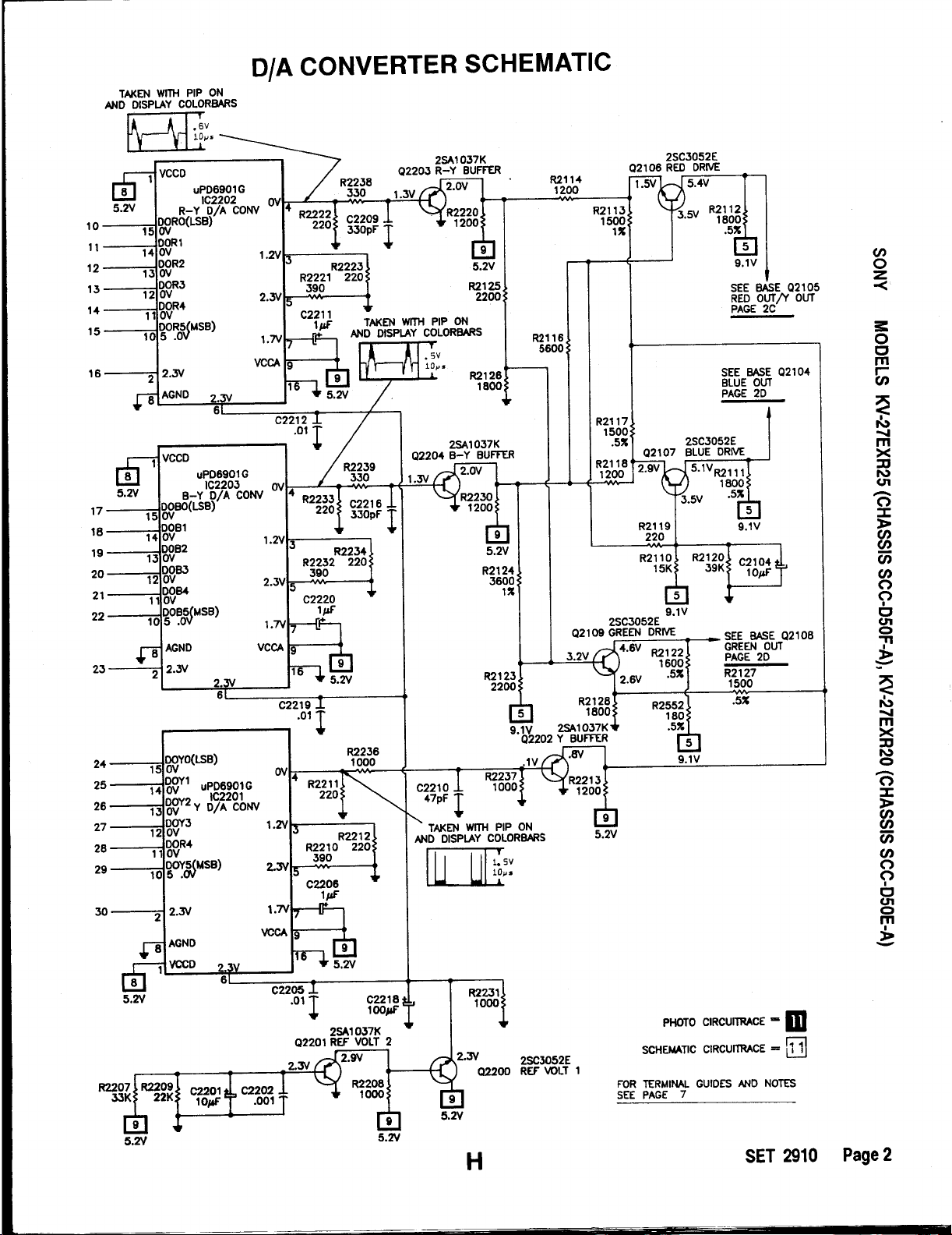
If waveform is present at pin 16 of IC2206, check for the proper waveform at pm 4 of Y D/A Conv IC (IC2201).
If the waveform is missing at at pin 4 of IC2201:
Check the voltages, waveforms, and components associated
with IC2201, pins
Cheek for the proper waveform at the emitter of YS Buffer Transmitter (42244).
(42
10
l),
Y Buffer 1 Transistor
of Y/C/J IC (IC2103).
1,46
thru 5 1, and 54 of IC2204.
video
(42 116),
waveform
(Q2102),
and
TROUBLESHOOTING continued
If the wave form is missing at the emitter of
Check the voltages, waveforms, and components associated
with 42244, pins 3 thru 6 of IC2 104, and pin 3 1 of IC2204.
If the waveform is present at pin 4 of IC2201:
Check the voltages, waveforms, and components associated
with Y Buffer Transistor (42202).
42244:
PIP CHROMA
Check for the waveforms at pins 20 and 22 of\Y/C/J IC (IC2103).
If the waveforms are missing:
Check the voltages, waveforms, and components associated
with pins 16 thru 22, and 31 of IC2 103.
Check the 3.58MHz oscillator at pins 15 and 18 of IC2103.
Check the voltages and components associated with Sub Color
Control and pin 13 of IC2103.
Check the voltages and components associated with Sub Hue
Control and pin 12 of IC2103.
If chroma waveform is present at pins 20 and 22 of IC2103, check
for the proper waveforms at pins 17 and 18 of A/D Conv IC
(IC2206).
If the waveforms are missing at pins 17 and 18 of IC2206:
Check the voltages, waveforms, and components associated
with R-Y Out Transistor (Q2103), and B-Y Out Transistor
(42114).
If the waveforms are present at
the proper waveforms at pins 4 of R-Y D/A Conv IC (IC2202), and
B-Y D/A Conv IC (IC2203).
If the waveforms am missing at pin 4 of IC2202, and IC2203:
Check the voltages, waveforms, and components associated
with IC2202, IC2203, PINP Conv IC (IC2204), and IC2206.
If the waveforms are present at pin 4 of IC2202, and IC2203:
Check the voltages, waveforms, and components associated
with R-Y Buffer Transistor (Q2203), B-Y Buffer Transistor
(Q2204), Red Drive Transistor (Q2106), Blue Drive Transistor
(Q2107), and Green Drive Transistor (42109).
pins
17 and 18 of IC2206, check for
SET 2910 Page 1
 Loading...