

SONY KV-25R2A, KV-25R2D, KV-25R2E, KV-25R2K, KV-25R2R SERVICE MANUAL 4
SELF-DIAGNOSTIC FUNCTION
®
SERVICE MANUAL FE-1
MODEL
KV-25R2A
KV-25R2D
KV-25R2E
COMMANDER DEST CHASSIS NO.
RM-883 Italian SCC-Q06J-A
RM-883 AEP SCC-Q04J-A
RM-883 Spanish SCC-Q05J-A
MODEL
KV-25R2K
KV-25R2R
COMMANDER DEST CHASSIS NO.
RM-883 OIRT SCC-Q03Q-A
RM-883 OIRT SCC-Q03P-A
CHASSIS
MICROFILM
/
MENU
PROGR
RM-883
TRINITRON
1
®
COLOR TV
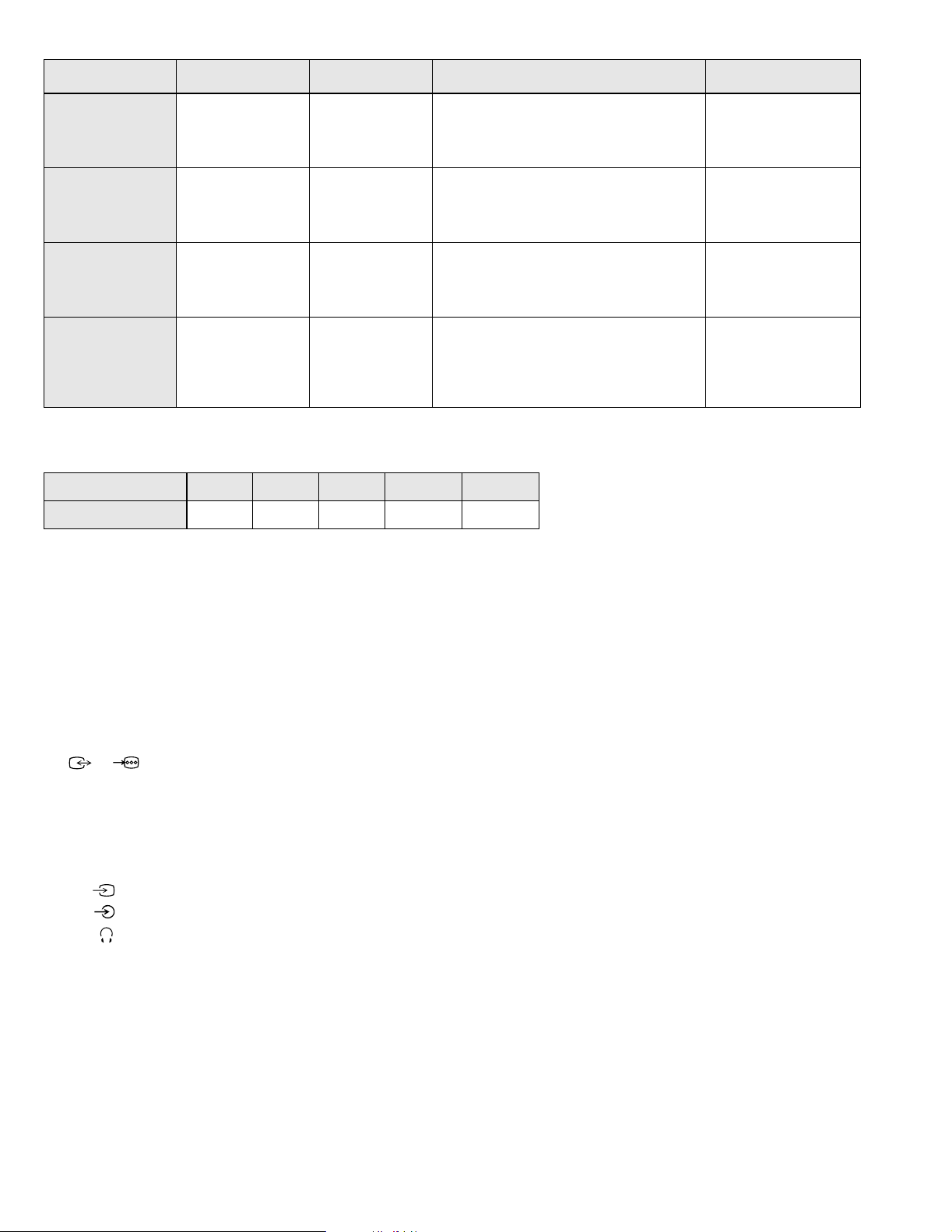
ITEM MODEL Television System Stereo System Channel Coverage Color System
Italian
AEP
Spanish
OIRT
MODEL 25R2A 25R2D 25R2E 25R2K 25R2R
Power Consumption
B/G/H GERMAN Stereo
B/G/H GERMAN Stereo
B/G/H, DK
B/G/H, D/K
95W 95W 95W 95W 95W
GERMAN/NICAM
Stereo
KV-25R2K
GERMAN/NICAM
Stereo
KV-25R2R
GERMAN Stereo
VHF : E02-E12, A-H2
UHF : E21-E69
CABLE TV : S01-S05, S1-S20
HYPER : S21-S41
VHF : E02-E12, A-H2, R01-R12
UHF : E21-E69, B21-B69, R21-R69, F21-F69
CABLE TV : S01-S05, S1-S20
HYPER : S21-S41
VHF : E02-E12, A-H2, R01-R12
UHF : E21-E69, R21-R69
CABLE TV : S01-S05, S1-S20
HYPER : S21-S41
VHF : E2-E12, R01-R12, A-H2
UHF : E21-E69, R21-R69
CABLE TV : S01-S05, S1-S20
HYPER : S21-S41
PAL, SECAM
NTSC4.43, NTSC3.58
(VIDEO IN)
PAL, SECAM
NTSC4.43, NTSC3.58
(VIDEO IN)
PAL, SECAM
NTSC4.43, NTSC3.58
(VIDEO IN)
PAL, SECAM
NTSC4.43, NTSC3.58
(VIDEO IN)
[PICTURE TUBE] Super Trinitron
Approx. 63 cm (25 inches)
(Approx. 59 cm picture measured
diagonally)
110 degree deflection
Input/Output Terminals
[REAR]
1/
21-pin Euro connector (CENELEC standard).
- Inputs for Audio and Video signals.
- Inputs for RGB.
- Outputs of TV Video and Audio signals.
[FRONT]
2
Video input - phono jack
Audio inputs - phono jacks
Headphone jack : stereo minijack
Sound output 2x14W (Music Power)
Power requirements 220 - 240V
Dimensions Approx 604x549x508mm
Weight Approx 31kg
Supplied accessories RM-883 Remote Commander (1)
IEC designated R6 battery (2)
Other features NICAM*, FASTEXT, TOPTEXT
* (KV-25R2E/25R2K only)
[RM-883]
Remote control system Infrared control
Power requirements 3V dc
2 batteries IEC designation
R6 (size AA)
Dimensions Approx 65x225x21mm (w/h/d)
Weight Approx 157g (Not including battery)
Design and specifications are subject to change without notice.
2
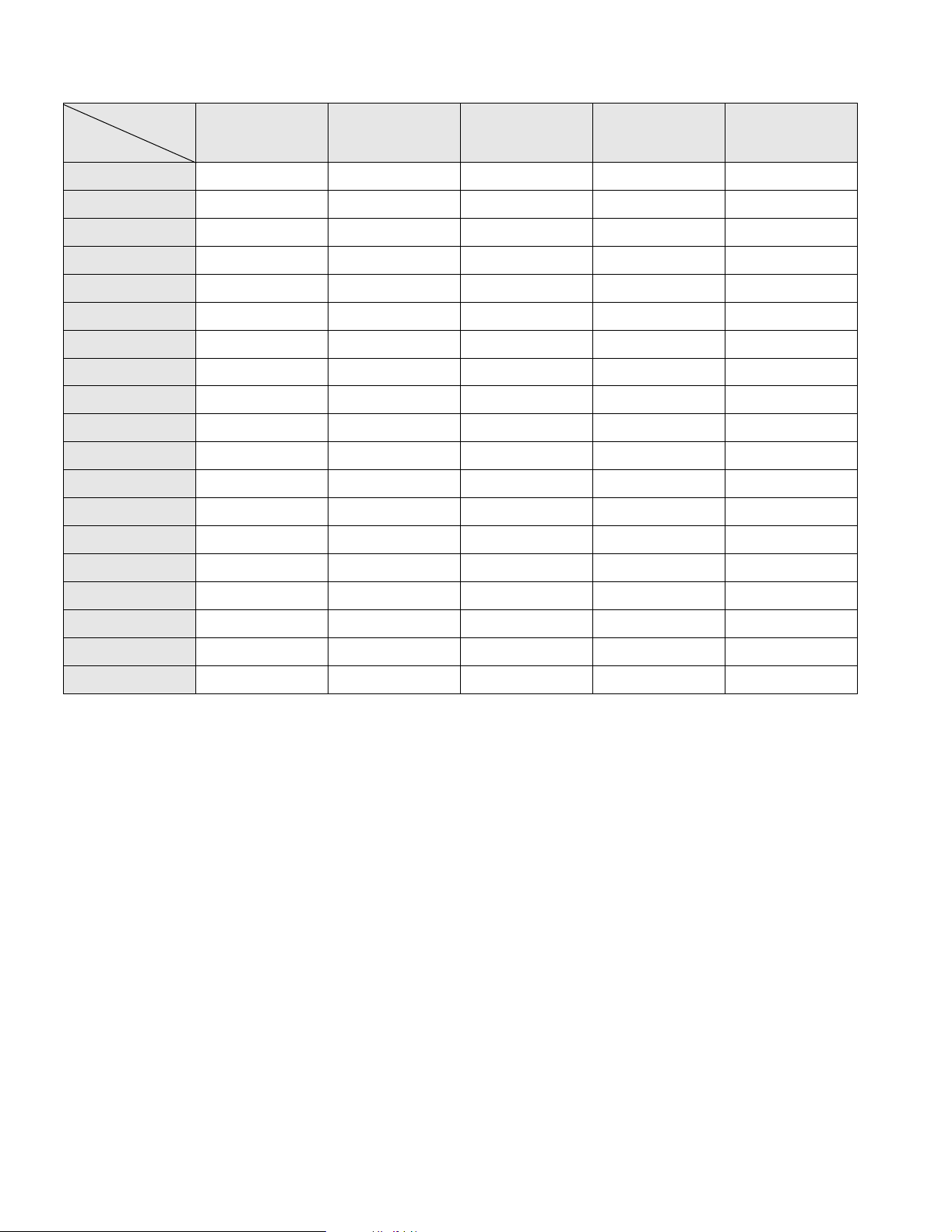
Item
Model Name
KV -25R2A KV -25R2D KV-25R2E KV-25R2K KV -25R2R
Pal Comb
PIP
Woofer Box
Scart 1
Scart 2
Front in (3)
Scart 4
Projector
AKB in 16:9 mode
Norm B/G
Norm I
Norm D/K
Norm AUS
Norm L
Norm SAT
Norm M
Teletext
OFF OFF OFF OFF OFF
OFF OFF OFF OFF OFF
OFF OFF OFF OFF OFF
ON ON ON ON ON
OFF OFF OFF OFF OFF
ON ON ON ON ON
OFF OFF OFF OFF OFF
OFF OFF OFF OFF OFF
ON ON ON ON ON
ON ON ON ON ON
OFF OFF OFF OFF OFF
OFF OFF ON ON ON
OFF OFF OFF OFF OFF
OFF ON OFF OFF OFF
OFF OFF OFF OFF OFF
OFF OFF OFF OFF OFF
ON ON ON ON ON
Nicam Stereo
Language Preset
OFF OFF ON ON OFF
Italian German Spanish OIRT OIRT
3
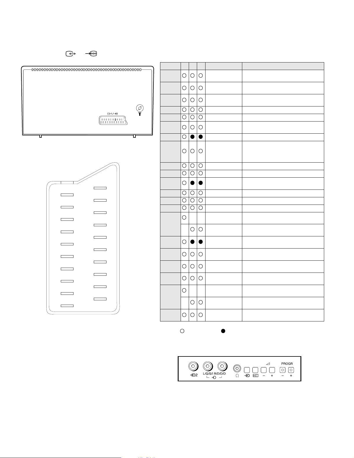
21 pin connector ( 1/ )
21
19
17
15
13
11
9
7
5
3
1
20
18
16
14
12
10
8
6
4
2
Pin No 1 2 4 Signal Signal level
1
2
3
4
5
6
7
8
9
10
11
12
13
14
15
_ (S signal Chroma
16
17
18
19
20
_ Video input
21
Audio output B
(right)
Audio output B
(right)
Audio output A
(left)
Ground (audio)
Ground (blue)
Audio input A
(left)
Blue input 0.7 +/- 3dB, 75 ohms positive
Function select
(AV control)
Ground (green)
Open
Green Green signal : 0.7 +/- 3dB, 75 ohms,
Open
Ground (red)
Ground (blanking)
_ _ Red input 0.7 +/- 3dB, 75 ohms, positive
input)
Blanking input
(Ys signal)
Ground (video
output)
Ground (video
input)
Video output 1V +/- 3dB, 75ohms, positive sync 0.3V
_ _ Video input 1V +/- 3dB, 75ohms, positive sync 0.3V
Y (S signal)
Common ground
(plug, shield)
Standard level : 0.5V rms
Output impedence : Less than 1kohm*
Standard level : 0.5V rms
Output impedence : More than 10kohm*
Standard level : 0.5V rms
Output impedence : Less than 1kohm*
Standard level : 0.5V rms
Output impedence : More than 10kohm*
High state (9.5-12V) : Part mode
Low state (0-2V) : TV mode
Input impedence : More than 10K ohms
Input capacitance : Less than 2nF
positive
0.3 +/- 3dB, 75 ohms, positive
High state (1-3V) Low state (0-0.4V)
Input impedence : 75 ohms
(-3+10dB)
(-3+10dB)
1V +/- 3dB, 75ohms, positive sync 0.3V
(-3+10dB)
Connected Not Connected (open) * at 20Hz - 20kHz
4

TABLE OF CONTENTS
Section Title Page Section Title Page
1. GENERAL
4. CIRCUIT ADJUSTMENTS
Overview of TV buttons .....................6
Using Select Mode .....................6
Adjusting the Picture .....................7
Adjusting the Sound .....................7
Using the Sleep Timer .....................8
Using the Wake Up Timer .....................8
Viewing Teletext .....................9
Exchanging Programme Pos .....................9
Manually Tuning the TV .....................10
Fine-Tuning Channels .....................10
Using Optional Equipment .....................11
Troubleshooting .....................11
2. DISASSEMBLY
2-1. Rear Cover Removal .....................12
2-2. Chassis Assy Removal .....................12
2-3. Service Position .....................13
2-4. S1 Board Removal .....................13
2-5. Picture Tube Removal .....................14
3. SET-UP ADJUSTMENTS
3-1. Beam Landing .....................15
3-2. Convergence .....................16
3-3. Screen [G2] White Balance .....................18
3-4. Focus .....................18
4-1. Electrical Adjustments .....................19
4-2. Test Mode 2 .....................22
4-3. FE-1 Self Diagnostic Software .....................23
5. DIAGRAMS
5-1. Block Diagram .....................25
5-2. Circuit Board Location .....................30
5-3. Schematic Diagrams and
Printed Wiring Boards .....................30
* A Board .....................35
* S1 Board .....................40
* C Board .....................43
5-4. Semiconductors .....................45
5-5. IC Blocks .....................47
6. EXPLODED VIEWS
6-1. Chassis .....................48
6-2. Picture Tube .....................49
7. ELECTRICAL PARTS LIST
.....................50
CAUTION
SHORT CIRCUIT THE ANODE OF THE PICTURE TUBE AND THE
ANODE CAP TO THE METAL CHASSIS, CRT SHIELD, OR THE
CARBON PAINTED ON THE CRT, AFTER REMOVAL OF THE
ANODE CAP
WARNING !!
AN ISOLATING TRANSFORMER SHOULD BE USED DURING ANY
SERVICE WORK TO AVOID POSSIBLE SHOCK HAZARD DUE TO
LIVE CHASSIS. THE CHASSIS OF THIS RECEIVER IS DIRECTLY
CONNECTED TO THE POWER LINE.
SAFETY-RELATED COMPONENT WARNING !!
COMPONENTS IDENTIFIED BY SHADING AND MARKED ON
THE SCHEMATIC DIAGRAMS, EXPLODED VIEWS AND IN THE
PARTS LIST ARE CRITICAL FOR SAFE OPERATION. REPLACE
THESE COMPONENTS WITH SONY PARTS WHOSE PART NUMBERS
APPEAR AS SHOWN IN THIS MANUAL OR IN SUPPLEMENTS
PUBLISHED BY SONY.
ATTENTION
APRES AVOIR DECONNECTE LE CAP DE’LANODE,
COURT-CIRCUITER L’ANODE DU TUBE CATHODIQUE ET
CELUI DE L’ANODE DU CAP AU CHASSIS METALLIQUE
DE L’APPAREIL, OU AU COUCHE DE CARBONE PEINTE
SUR LE TUBE CATHODIQUE OU AU BLINDAGE DU TUBE
CATHODIQUE.
ATTENTION !!
AFIN D’EVITER TOUT RISQUE D’ELECTROCUTION PROVENANT
D’UN CHÁSSIS SOUS TENTION, UN TRANSFORMATEUR
D’ISOLEMENT DOIT ETRE UTILISÈ LORS DE TOUT DÈPANNAGE.
LE CHÁSSIS DE CE RÈCEPTEUR EST DIRECTMENT RACCORDÈ
Á L’ALIMENTATION SECTEUR.
ATTENTION AUX COMPOSANTS RELATIFS Á LA
SÈCURITÈ !!
LES COMPOSANTS IDENTIFIÈS PAR UNE TRAME ET PAR UNE
MARQUE SUR LES SCHÈMAS DE PRINCIPE, LES VUES
EXPLOSÈES ET LES LISTES DE PIECES SONT D’UNE IMPORTANCE
CRITIQUE POUR LA SÈCURITÈ DU FONCTIONNEMENT, NE LES
REMPLACER QUE PAR DES COMPSANTS SONY DONT LE NUMÈRO
DE PIÈCE EST INDIQUÈ DANS LE PRÈSENT MANUEL OU DANS
DES SUPPLÈMENTS PUBLIÈS PAR SONY.
5
Basic TV Features
8
Additional TV Features
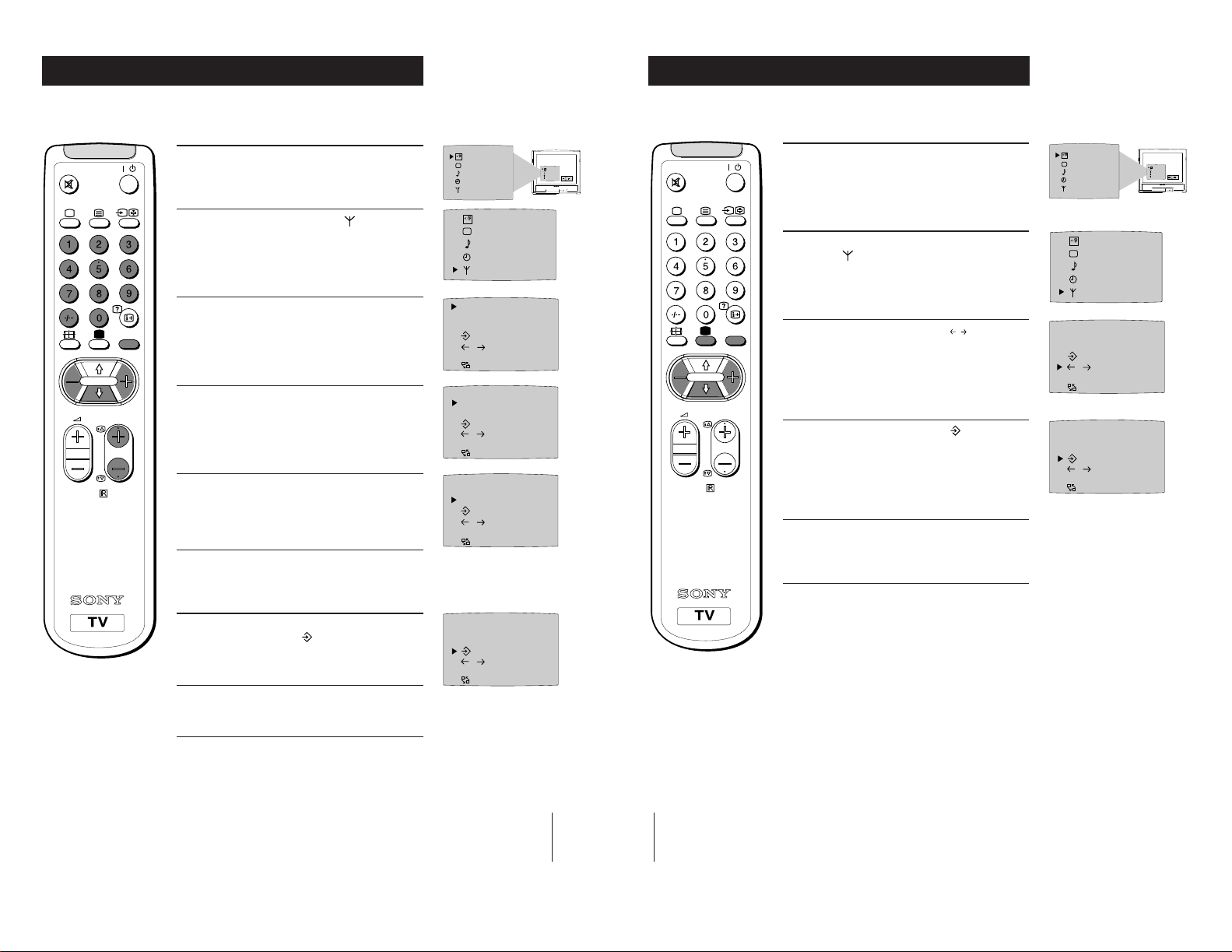
Using Select Mode
You can select different preset picture and sound modes.
1 Press the MENU button on the remote control to
display the menu on the TV screen.
2 With the cursor pointing at the
SELEC
T
symbol on the
TV screen as shown, press the yellow button.
3 Press the blue button to select the desired mode:
Personal Mode - reverts to settings made in
“Adjusting the Picture and Sound” sections of
the manual
Movie Mode - for films
Live Mode -for live broadcast programmes
4 Press the MENU button to remove the menu
display from the TV screen.
Note: The mode selected in step 3 is now stored.
RM-883
PROGR
MENU
/
OFF
SELEC
T
Changing Modes Quickly
1
Press the button on the remote control to display
the three different modes.
2 Press the button again to select your desired
mode.
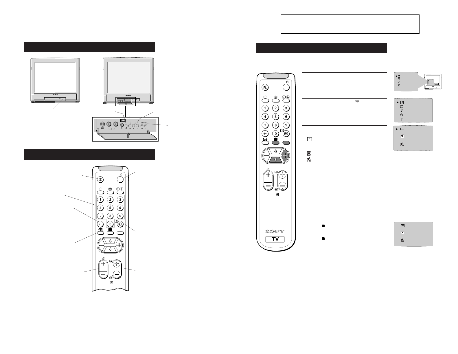
Overview of TV Buttons
SECTION 1 GENERAL
The operating instructions mentioned here are partial abstracts
from the Operating Manual. The page numbers of the Operating
Instruction Manual remain as in the manual.
On/Off Switch.
Overview of Remote Control Buttons
6
To Mute Sound
Press to mute TV sound. Press again
to restore the sound.
To Select Channels
Press to select channels.
For double-digit programme
numbers, e.g. 23, press -/-- first,
then the buttons 2 and 3.
If you enter an incorrect first
digit, this should be corrected by
entering another digit (0 - 9) and
then selecting -/-- button again to
enter the programme number of
your choice
To Change Screen Format
Press to view programmes in 16:9
mode.
Press again to return to 4:3 mode.
To Adjust TV Volume
Press to adjust the volume of the TV.
Video Input Button.
(selects input signals
from VCR etc.).
L/G/S/I R/D/D/D
2
PROGR
RM-883
/
MENU
Auto Tune
Button.
Volume Control Buttons.
Programme Up or
Down Buttons.
(selects TV channels).
To Temporarily Switch Off TV
Press to temporarily switch off TV. Press
again to switch on TV from standby
mode.
To save energy we recommend switching off
completely when TV is not in use.
NOTE: After 15 - 30 minutes without a
TV signal and without any button being
pressed, the TV switches automatically
into standby mode.
To Reveal On Screen Information
Press to reveal all on-screen indications.
Press again to cancel.
To Select Channels
Press to select channels.
SELEC
T
OFF
SELEC
T
OFF
OK
7
Additional TV Features
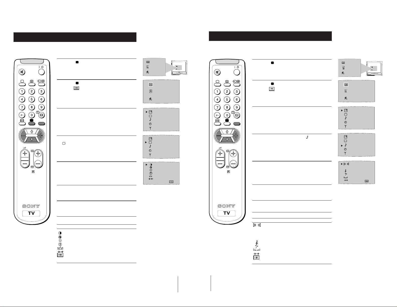
Adjusting the Picture
Additional TV Features
Adjusting the Sound
Although the picture is adjusted at the factory, you can modify it to suit your own
requirement.
1
Press the button on the remote control to
/
MENU
PROGR
display the three different modes on the TV
screen.
2
Press the button to highlight the personal mode
symbol
3
Press the MENU button to display the menu on
the TV screen.
4
Press the blue button on the control to select the
button.
as shown.
symbol on the TV screen then press the yellow
7
5
Press the blue button to select the item you wish
RM-883
to change (see below).
6
Press the red or yellow button to alter the selected
item.
SELEC
T
SELEC
T
OFF
OFF
IIIIIIIIIIIIIII- - - - - IIIIIIIIIIIIIII- - - - - IIIIIIIIIIIIIII- - - - - -
IIIIIIIIIIIIIII- - - - - -
IIIIIIIIIIIIIII- - - - - -
Although the sound is adjusted at the factory, you can modify it to suit your own
requirement.
1 Press the button on the remote control to
/
display the three different modes on the TV
screen.
2 Press the button to highlight the personal mode
symbol
as shown.
3 Press the MENU button to display the menu on
the TV screen.
MENU
4 Press the blue button to select the symbol on the
TV screen then press the yellow button.
PROGR
5 Press the blue button to select the item you wish to
RM-883
change (see below).
6 Press the red or yellow button to alter the selected
item.
SELEC
T
SELEC
T
DSP
IIIIIIIIIIIIIIIIIIIIIII - - - - - IIIIIIIIIIIIIIIII - - - - - - - - IIIIIIIIIIIIIII- -
OFF
OFF
MONO STEREO
ON OFF
IIIIIIIIIIIIIII
7
Press the MENU button to remove the menu
display from the TV screen.
Symbol Item
• Contrast
• Colour
• Brightness
• Sharpness
• Hue control (only for NTSC video signals)
• Reset - resets to factory preset picture level
• Represents the mode selected in the “Using
Select Mode” section.
7 Press the MENU
button to remove the menu
display from the TV screen.
Symbol Item
DSP • On/Off (digital sound processor)
9
10
• Mono/Stereo
A:Channel 1 sound or Mono sound/
B:Channel 2 sound (to select your desired
language from a dual sound broadcast)
• Treble
• Bass
• Balance
• Reset (resets to factory preset sound level)
• Represents the mode selected in the “Using
Select Mode” section of the manual.
Additional TV Features
Additional TV Features
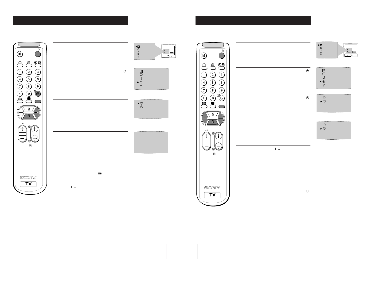
Using the Sleep Timer
The TV may be set to switch automatically to the standby mode after a length of time
chosen by you. You may set the time in 15 minute steps up to 4 hours.
1
/
MENU
PROGR
8
RM-883
Press the MENU button on the remote control to
display the menu on the TV screen.
2
Press the blue button on the control to select the
symbol on the TV screen, then press the yellow
button.
3
Press the yellow button repeatedly until the
required amount of time delay appears on the
screen.
4
Once the time delay has been selected, press the
MENU button to remove the on-screen display.
One minute before standby, the display shown
appears on the screen.
Notes:
• When watching TV, press the
time remaining.
• To return to normal operation from standby mode,
press the
button.
button to display
SELEC
0:59
Using the Wake Up Timer
The TV may be set to switch on automatically after a length of time chosen by you.
You may set the time in 15 minute steps up to 12 hours.
SELEC
1
T
OFF
SELEC
T
OFF
0:45
OFF
SELEC
T
OFF
OK
/
MENU
PROGR
Press the MENU button on the remote control to
display the menu on the TV screen.
2
Press the blue button on the control to select the
symbol on the TV screen, then press the yellow
button.
3
Press the blue button on the control to select the
symbol on the TV screen, then press the yellow
button.
4
Press the red or yellow button to set the time.
0:00 (OFF) 0:15 0:30 0:45 -----12:00
5
RM-883
Press the standby button
The standby indicator on the TV flashes regularly
to indicate that the Wake Up Timer is active.
After the selected length of time, the TV switches
on automatically.
.
Notes:
• If you use the “Wake Up Timer” to switch the TV
on and for one hour after switching on, no TV or
Remote Control button is pressed, the TV switches
itself back into Standby mode and the indicator
on the TV lights.
• Any temporary power failure will cause a
misfunction in the “Wake Up Timer” and you will
have to reset the “Wake Up Timer”.
T
OFF
SELEC
T
OFF
OFF
OFF
OFF
0:45
SELEC
T
OFF
OK
11
12
Additional TV Features
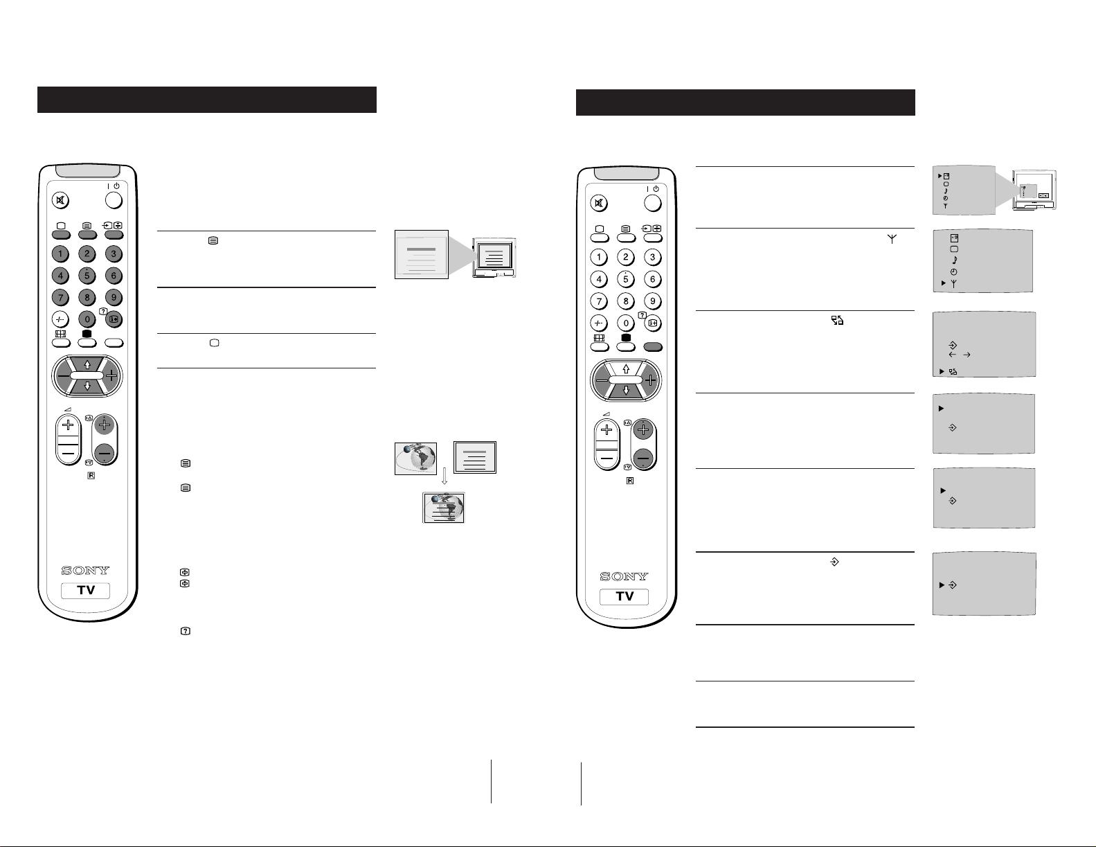
Viewing Teletext
Additional TV Features
Exchanging Programme Positions
Teletext is an information service transmitted by most TV stations.
Selecting Teletext
/
MENU
PROGR
9
RM-883
Press a number button on the remote control to
1
select the channel which carries the teletext service
you wish to receive.
2
Press the button on the remote control to switch
on teletext.
3
Input three digits for the page number using the
numbered buttons on the control.
4
Press the button to switch off teletext.
Note: Teletext errors may occur if the broadcasting
signals are weak.
Using Other Teletext Functions
To Superimpose Teletext on to the TV
Press
once in teletext mode or twice in TV mode to
superimpose teletext on to the TV screen.
again to cancel teletext mode.
Press
To Move to Next or Preceding Page
Press PROGR +/previous or next page.
on the remote control to select the
TELETEXT
Index
Programme
News
Sport
Weather
25
153
101
98
TELETEXT
Index
Programme
News
Sport
Weather
TELETEXT
Index
Programme
News
Sport
Weather
25
153
101
98
TELETEXT
Index
Programme
News
Sport
Weather
25
153
101
98
After tuning you may wish to change the order in which the channels appear on the
TV. You may wish for example to exchange the channel on programme number 8
with the channel on programme number 4.
SELEC
1
Press the MENU button on the remote control.
/
2
Press the blue button on the control to select on
25
153
101
98
MENU
PROGR
RM-883
the TV screen, then press the yellow button.
3
Press the blue button to select then press the
yellow button.
4
With the cursor pointing at PROGR on the TV
screen as shown, press PROGR + or - button until
the channel you wish to rearrange appears on
screen, then press the blue button once.
5
Press the red or yellow button to select the new
programme number (e.g. PROGR 04) for your
selected channel.
T
OFF
SELEC
T
OFF
PROGR 01
C
S
CH 05 IIIIIIIIIIIIIII- - - - -
on
F
C
OO
PROGR - +
01
PROGR - +
04
SELEC
T
OFF
OK
To Freeze a Teletext Page
Press
on the control to freeze the page.
Press
again to cancel the freeze.
Revealing concealed information (eg: answers
to a quiz).
to reveal information.
Press
Press again to conceal the information.
Using colour buttons to access pages
(Fastext/TOPtext)
When the colour coded menu appears at the bottom of
a page, press the colour button (green, red, yellow or
blue) to access the corresponding page.
13
14
6
Press the blue button to select then press the
yellow button to exchange the channels.
7
Repeat steps 4 to 6 if you wish to change the order
of the other channels on your TV, then press
MENU to return to normal TV screen.
8
Press the PROGR+/- button to view your selected
channels on their new programme numbers.
PROGR - +
04
Additional TV Features
Additional TV Features
Manually Tuning the TV
You have already tuned the TV to receive all available channels using the
`Automatically Tuning the TV' procedure at the start of this manual. You can
however carry out this operation manually using the following instructions.
1
Press the MENU button on the remote control to
/
MENU
PROGR
10
RM-883
display the menu on the TV screen.
2
Press the blue button to select the symbol on the
TV screen then press the yellow button.
3
With the cursor pointing at PROGR on the TV
screen as shown, press PROGR + or - button on the
remote control to allocate a programme number to
the channel (eg PROGR 01). For double digit
numbers e.g. 55, press the -/-- button on the remote
control then the corresponding numbered buttons.
4
Press the blue button to select the channel type
(C to preset a regular channel or S to preset a cable
channel) then press the yellow button to highlight
the desired channel type.
5
Press the blue button to select the tuning bar scale
then press the yellow or red button once to start the
channel search. (Yellow to search up the scale or
red to search down). When a channel is found it
appears on the TV screen.
6
If you do not wish to store this channel on the
programme number you selected, press the yellow
or red button to continue searching for the desired
channel.
7
If this is the channel you wish to store, press the
blue button to select the
then press the yellow button to store.
8
Repeat steps 3 to 7 if you wish to store more
channels then press the MENU
the menu from the TV screen.
symbol on the screen
button to remove
SELEC
T
OFF
SELEC
T
OFF
PROGR 01
S
C
CH 05 IIIIIIIIIIIIIII- - - - -
on
F
C
OO
PROGR 01
C
S
CH 05 IIIIIIIIIIIIIII- - - - -
on
F
OO
C
PROGR 01
C
S
CH 05 IIIIIIIIIIIIIII- - - - -
on
F
C
OO
PROGR 01
S
C
CH 05 IIIIIIIIIIIIIII- - - - -
on
F
OO
C
Fine-Tuning Channels
If a channel is slightly off tune, you can use this fine tune procedure to obtain a better
picture reception.
1 With the channel you wish to fine-tune on the
SELEC
T
OFF
OK
/
screen, press the MENU button on the remote
control. The menu display appears on the TV
screen.
2 Press the blue button on the remote control to
PROGR
RM-883
MENU
select the
the yellow button.
3 Press the blue button to select the
the TV screen then press the red or yellow button
to adjust the tuning.
4 Press the blue button to select the symbol on the
TV screen then press the yellow button to store.
symbol on the TV screen then press
symbol on
F
5 Press the MENU button to remove the menu from
the TV screen.
SELEC
T
OFF
SELEC
T
OFF
PROGR 01
CS
CH 05 IIIIIIIIIIIIIII- - - - -
on
F
C
OO
PROGR 01
S
C
CH 05 IIIIIIIIIIIIIII- - - - -
on
F
C
OO
SELEC
T
OFF
OK
15
16
Optional Connections
Using Optional Equipment
Additional Information
Troubleshooting
11
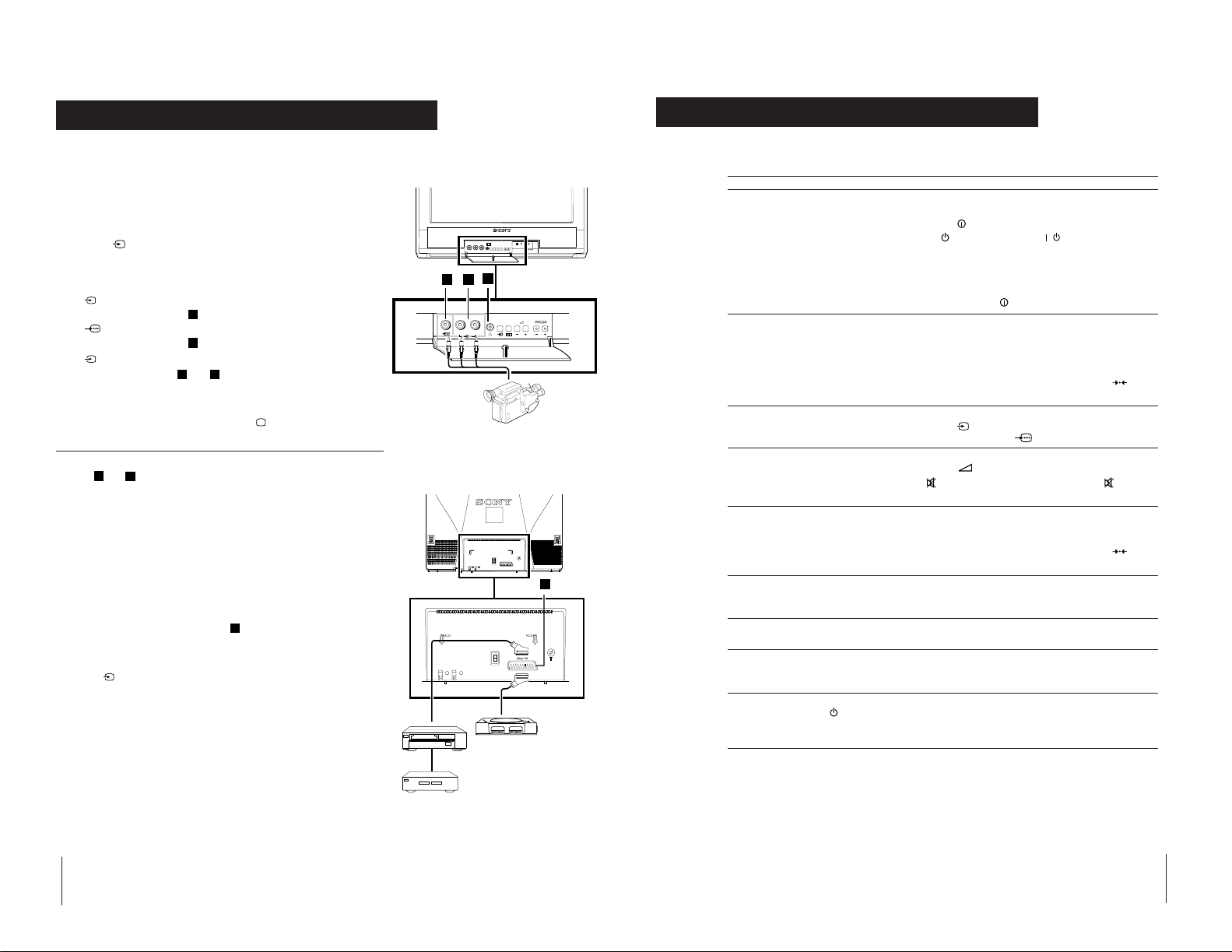
You can connect optional audio or video equipment to your TV, such as a VCR, a
camcorder or video games as shown.
Select and View the Input Signal
Connect your equipment to the designated TV socket.
1
2 Press
correct input symbol appears on the TV screen.
Symbol Input signals
button repeatedly on your remote control until the
the
• Audio/video input signal through the Euro AV
1
connector
• RGB input signal through the Euro AV
connector
2
• Audio/video input signal through the phono
sockets
A
D
D
and
B
3 Switch on the connected equipment.
4 To return to normal TV picture, press the
control.
Note: To avoid picture distortion, do not connect equipment to the
and D
A
connectors
at the same time.
button on the remote
Additional Information
Connecting a VCR
We recommend you tune in the VCR signal to TV programme number `0'
using the `Manually Tuning in the TV' section of this instruction manual.
Connecting Headphones
Plug in your headphones to the socket
For Mono Equipment
Connect the phono plug to the L/G/S/I socket on the front of the TV
and select
the `Adjusting the Sound' section of this manual and select `A' on the
sound menu screen.
input signal using the instructions above. Finally, refer to
2
on the front of the TV set.
C
Decoder
A
VCR
B
L/G/S/I R/D/D/D
Front of TV
C
Rear of TV
1
“PlayStation”
2
8mm/Hi8
camcorder
D
Here are some simple solutions to problems which may affect the picture and sound.
Problem Solution
No picture (screen is dark), no sound • Plug the TV in.
Poor or no picture (screen is dark), • Using the MENU system, select the Picture
but good sound Adjustment display.
Poor picture quality when watching • Press the button repeatedly on the remote control
a RGB video source. until the RGB symbol
Good picture, no sound • Press the +/– button on the remote control.
No colour on colour programmes • Using the MENU system, select the Picture
Distorted picture when changing • Turn off any equipment connected to the 21 pin
programmes or selecting teletext Euro connector on the rear of the TV.
Remote control does not function • Replace the batteries.
Noisy picture when viewing • Adjust fine tuning to obtain better picture reception.
TV channel
The standby indicator on the • Contact your nearest Sony service centre.
TV flashes even though the
“Wake Up Timer”is not in use.
• If you continue to have these problems, have your TV serviced by qualified personnel.
• Press the
• If the
programme number button on the remote control.
• Check the aerial connection.
• Check that the selected video source is on.
• Turn the TV off for 3 or 4 seconds and then turn it
on again using the
Adjust the brightness, picture and colour balance
levels.
• From the Picture Adjustment display select
return to the factory settings.
• If
on the remote control.
Adjustment display. Adjust the colour balance.
• From the Picture Adjustment display select to
return to the factory settings.
button on the front of TV.
indicator is on press
button on the front of the TV.
is displayed on the screen, press the button
button or a
to
is displayed on the screen.
• NEVER open the casing yourself.
18
19
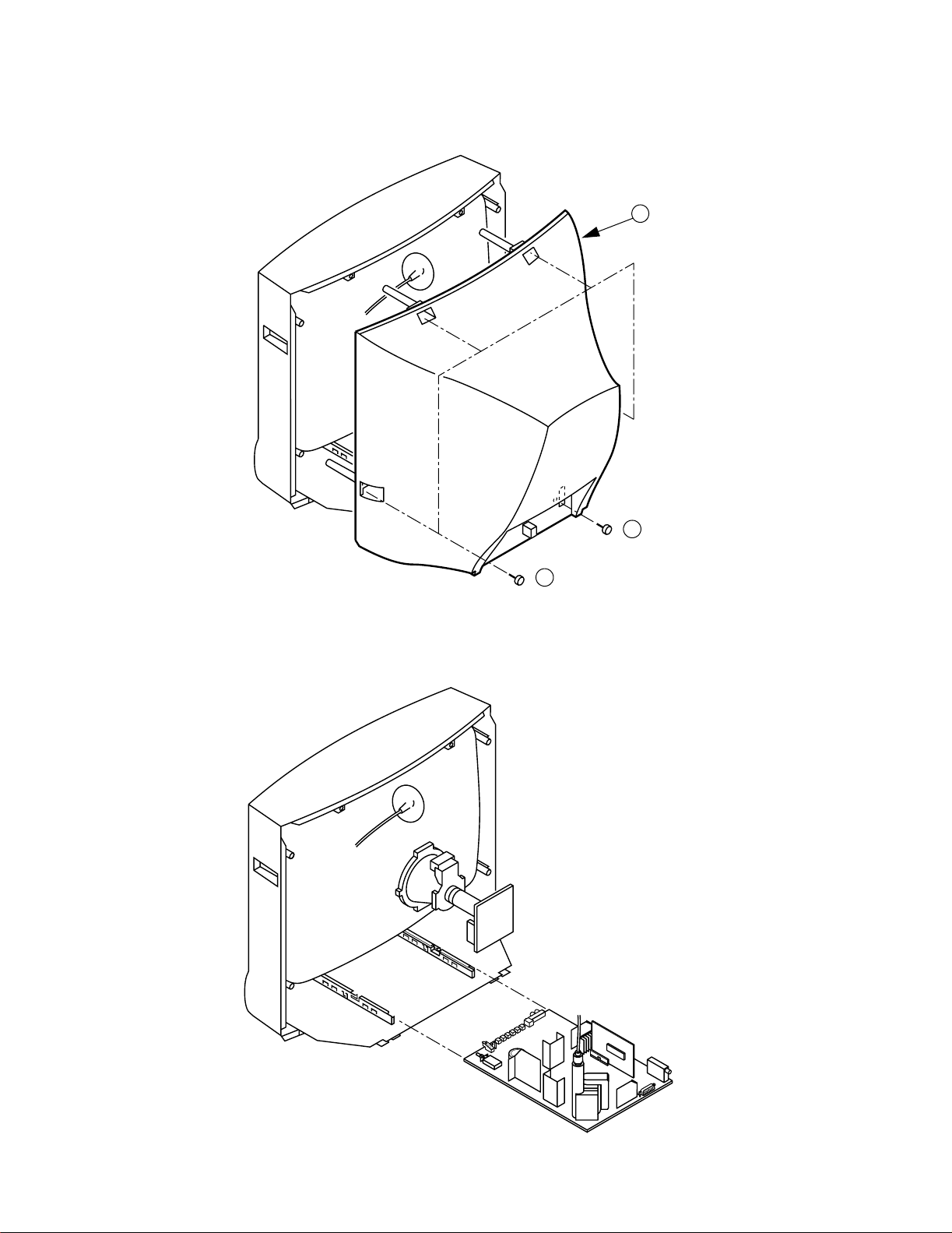
2-1. REAR COVER REMOVAL
SECTION 2
DISASSEMBLY
3 Rear Cover
2-2. CHASSIS ASSY REMOVAL
2 1 Screw BTV 4x16
1 4 Screws BTV 4x16
12
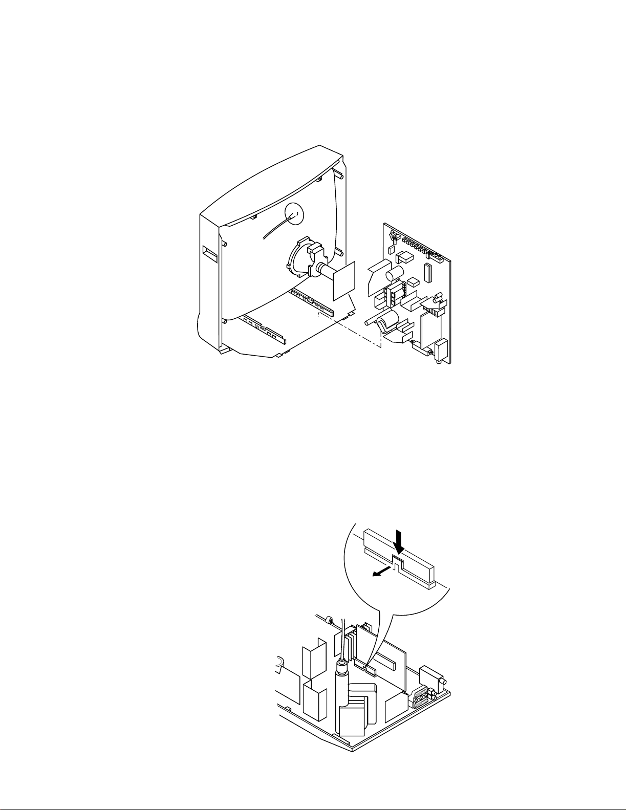
2-3. SERVICE POSITION
2-4. S1 BOARD REMOVAL
Release the clip indicated
13
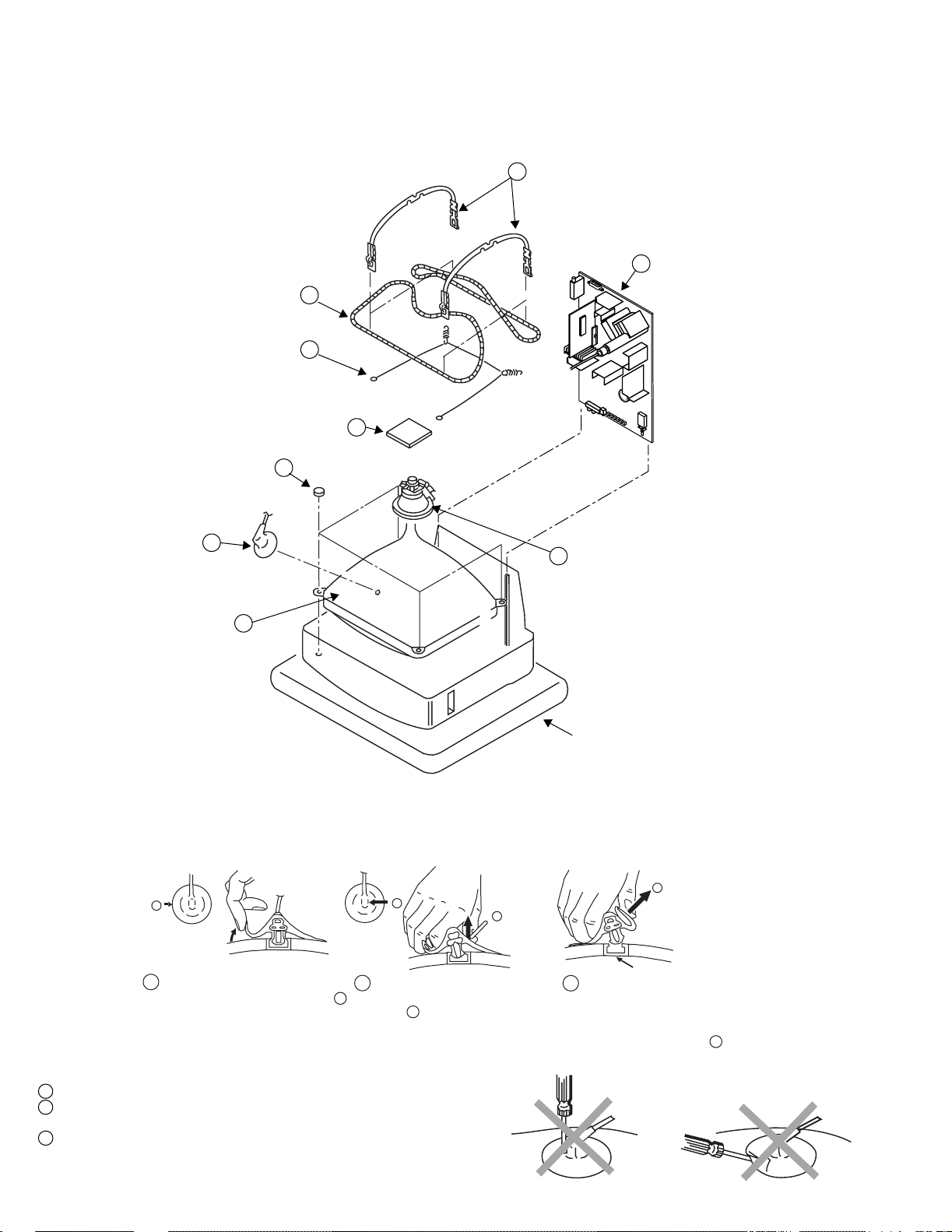
2-5. PICTURE TUBE REMOVAL
Degaussing coils 6
Spring Tension 7
C board 3
Four PT screws 8
5 DGC holders
2 Chassis assy
Anode cap 1
Deflection yolk 4
Picture tube 9
Cushion
• REMOVAL OF ANODE-CAP
Note : Short circuit the anode of the picture tube and the anode cap to the metal chassis, CRT shield or carbon paint on the CRT, after removing the anode.
* REMOVING PROCEDURES.
c
a
1
Turn up one side of the rubber cap in
the direction indicated by the arrow a
• HOW TO HANDLE THE ANODE-CAP
b
b
2 Using a thumb pull up the rubber cap
firmly in the direction indicated by the
arrow b
3 When one side of the rubber cap is
Anode button
separated from the anode button, the
anode-cap can be removed by turning
up the rubber cap and pulling it up in
the direction of the arrow c
1 To prevent damaging the surface of the anode-cap do not use sharp materials.
2 Do not apply too great a pressure on the rubber, as this may cause damage to the
anode connector.
3 A metal fitting called a shatter hook terminal is fitted inside the rubber cap.
Do not turn the rubber foot over excessively this may cause damage if the shatter
hook sticks out.
14
 Loading...