

SONY KV-25FX20A, KV-25FX20B, KV-25FX20D, KV-25FX20E, KV-25FX20K Service Manual
...
SERVICE MANUAL FE-1A CHASSIS
MODEL
COMMANDER DEST CHASSIS NO.
KV-25FX20A
KV-25FX20B
KV-25FX20D
KV-25FX20E
KV-25FX20K
KV-25FX20R
RM-887 Italian SCC-Q32B-A
RM-887 French SCC-Q33B-A
RM-887 AEP SCC-Q31B-A
RM-887 Spanish SCC-Q34B-A
RM-887 OIRT SCC-Q36C-A
RM-887 OIRT SCC-Q36D-A
MODEL
COMMANDER DEST CHASSIS NO.
KV-29FX20A
KV-29FX20B
KV-29FX20D
KV-29FX201D
KV-29FX20E
KV-29FX201E
KV-29FX20K
KV-29FX20R
KV-29FX20U
RM-887 Italian SCC-Q32A-A
RM-887 French SCC-Q33A-A
RM-887 AEP SCC-Q31A-A
RM-887 AEP SCC-Q31E-A
RM-887 Spanish SCC-Q34A-A
RM-887 ESP SCC-Q34E-A
RM-887 OIRT SCC-Q36B-A
RM-887 OIRT SCC-Q36A-A
RM-887 UK SCC-Q35A-A
MICROFILM
TRINITRON
1
®
COLOR TV
®
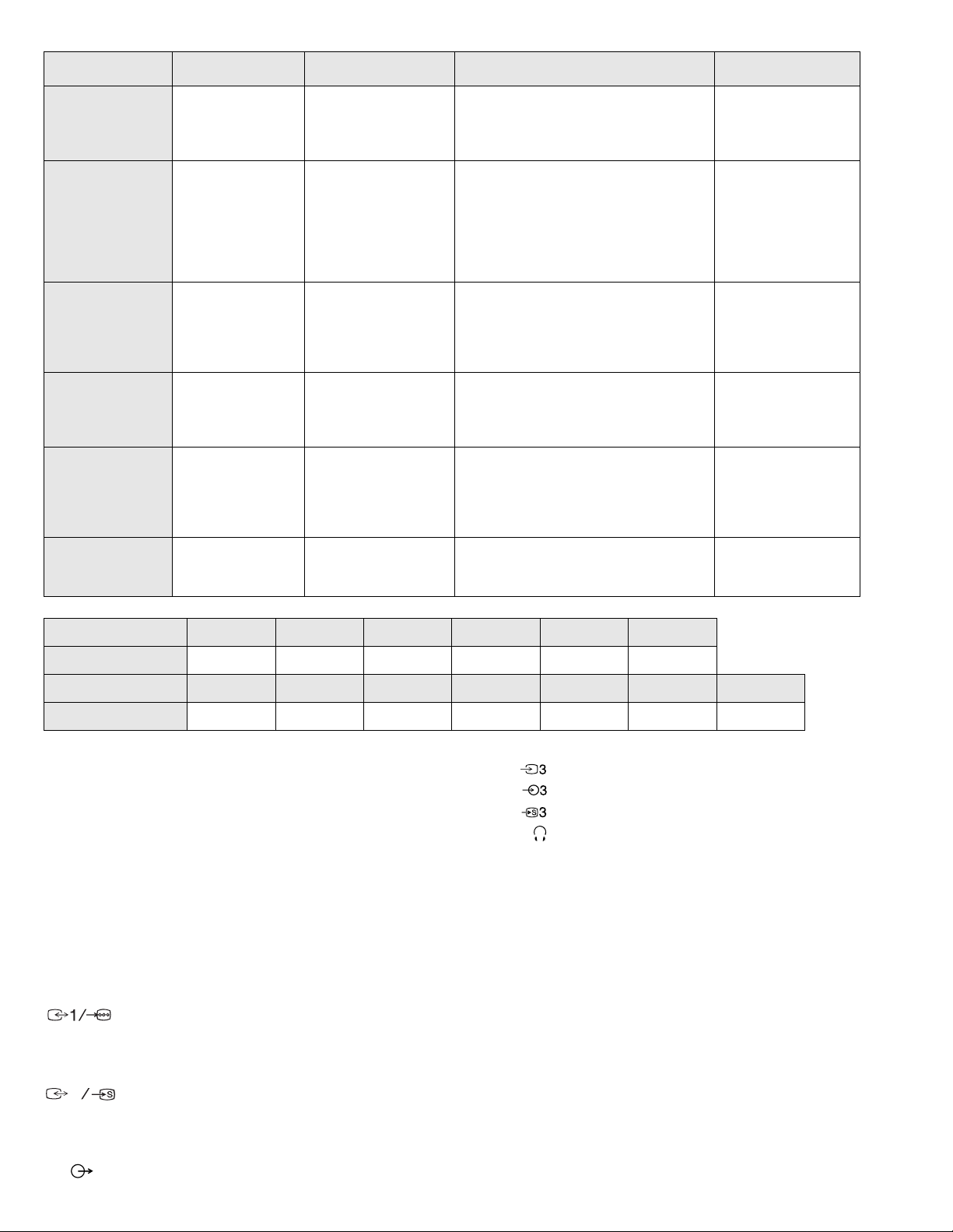
ITEM MODEL Tele vision System Stereo System Channel Coverage Color System
Italian B/G/H GERMAN Stereo
French B/G/H, D/K, L, I GERMAN/NICAM
AEP B/G/H GERMAN Stereo
Spanish B/G/H, D/K GERMAN/NICAM
OIRT B/G/H, D/K
UK I NICAM Stereo UHF : B21-B69
Stereo
Stereo
KV-25FX20K/29FX20K
GERMAN/NICAM
Stereo
KV-25FX20R/29FX20R
GERMAN Stereo
ITALIA VHF : A-H2 (C) UHF : 21-69 PAL
B/G/H VHF : E2-E12 UHF : E21-E69
CABLE TV (1) : S1-S41
CABLE TV (2) : S01-S05, M1-M10, U1-U10
L VHF : F02-F10 UHF : F21-F60
CABLE : B-Q B/G/H VHF : E2-E12
UHF : E21-E69
CABLE TV (1) : S1-S41
CABLE TV (2) : S01-S05, M1-M10, U1-U10
ITALIA VHF : A-H2 (C) UHF : 21-69
I UHF : B21-B69
PAL B/G/H VHF : E2-E12 UHF : E21-E69
CABLE TV (1) : S1-S41
CABLE TV (2) : S01-S05, M1-M10, U1-U10
ITALIA VHF : A-H2 (C) UHF : 21-69
D/K VHF : R01-R12 UHF : R21-R69
PAL B/G VHF : E2-E12 UHF : E21-E69
CABLE TV (1) : S1-S41
CABLE TV (2) : S01-S05, M1-M10, U1-U10
ITALIA VHF : A-H2 (C) UHF : 21-69
B/G/H VHF : E2-E12 UHF : E21-E69
CABLE TV (1) : S1-S41
D/K VHF : R01-R12 UHF : R21-R69
PAL, SECAM
NTSC4.43, NTSC3.58
(VIDEO IN)
PAL, SECAM
NTSC4.43, NTSC3.58
(VIDEO IN)
PAL, SECAM
NTSC4.43, NTSC3.58
(VIDEO IN)
PAL, SECAM
NTSC4.43, NTSC3.58
(VIDEO IN)
PAL, SECAM
NTSC4.43, NTSC3.58
(VIDEO IN)
PAL
NTSC4.43, NTSC3.58
(VIDEO IN)
MODEL 25FX20A 25FX20B 25FX20D 25FX20E 25FX20K 25FX20R
Power Consumption 100W 100W 100W 100W 100W 100W
MODEL 29FX20A 29FX20B 29FX20D 29FX20E 29FX20K 29FX20R 29FX20U
Power Consumption 120W 120W 120W 120W 120W 120W 150W
[PICTURE TUBE]
KV-25FX20 FD Trinitron
Approx. 63cm (25 inches)
(Approx. 59cm picture measured
diagonally)
110 degree deflection
KV-29FX20 FD Trinitron
Approx. 72cm (29 inches)
(Approx. 68cm picture measured
diagonally)
110 degree deflection
Input/Output Terminals
[FRONT]
Video input - phono jack
Audio inputs - phono jacks
S Video input - 4 pin din
Headphone jacks : stereo minijack
Sound output 2 x 14W (Music Power)
Subwoofer 30W (Music Power)
Power requirements 220 - 240V
Dimensions
KV-25FX20 Approx 655x509x476mm (w/h/d)
KV-29FX20 Approx 746x569x516mm (w/h/d)
Weight
[REAR]
21-pin Euro connector (CENELEC standard).
- Inputs for A ud i o and Vi deo signals.
- Inputs for RGB.
- Outputs of TV Video and Audio si gnals.
2
21-pin Euro connector.
- inputs for Audio and Video signals.
KV-25FX20 Approx 37kg
KV-29FX20 Approx 47.5kg
Supplied accessories RM-887 Remote Commander (1)
IEC designated R6 battery (2)
Other features NICAM*, FASTEXT, TOPTEXT
(KV-25FX20B/25FX20E/25FX20K/
*
KV-29FX20B/29FX20E/29 FX20K/
KV-29FX20U only)
- inputs for S Video.
- outputs for Audio and Video signals (selectable).
Phono Jack
- Outputs for Audio Signals
2
[RM-887]
Remote control system Infrared control
Power requirements 3V dc
2 batteries IEC designation
R6 (size AA)
Dimensions Approx 44x209x23mm (w/h/d)
Weight Approx 89g (Not including battery)
Design and specifications are subject to change without notice.
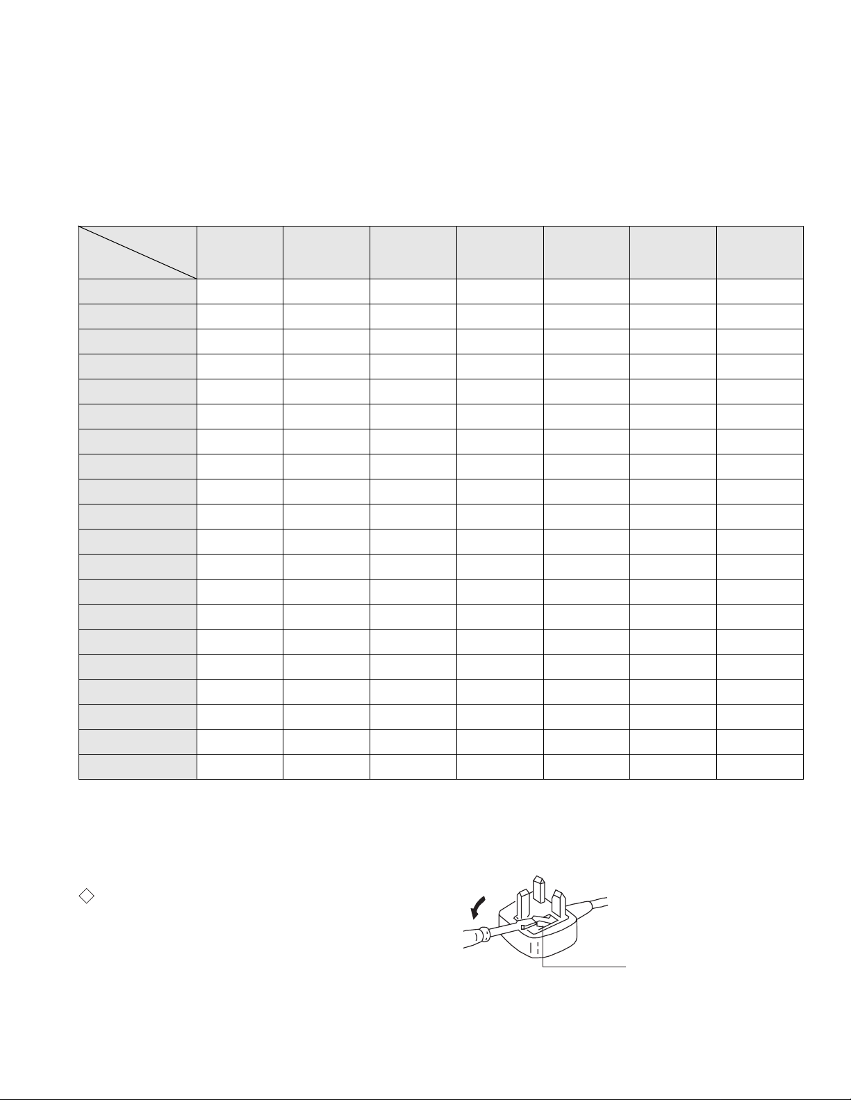
Model Name
Item
Pal Comb OFF OFF OFF OFF OFF OFF OFF
PIP OFF OFF OFF OFF OFF OFF OFF
RGB Priority OFF ON ON ON OFF OFF OFF
Woofer Box ON ON ON ON ON ON ON
Scart 1 ON ON ON ON ON ON ON
Scart 2 ON ON ON ON ON ON ON
Front in (3) ON ON ON ON ON ON ON
Scart 4 OFF OFF OFF OFF OFF OFF OFF
Projector OFF OFF OFF OFF OFF OFF OFF
AKB in 16:9 mode ON ON ON ON ON ON ON
Norm B/G ON ON ON ON ON ON OFF
Norm I OFF ON OFF OFF OFF OFF ON
Norm D/K OFF ON OFF ON ON ON OFF
Norm AUS OFF OFF OFF OFF OFF OFF OFF
KV-25FX20A
KV-29FX20A
KV-25FX20B
KV-29FX20B
KV-25FX20D
KV-29FX20D
KV-25FX20E
KV-29FX20E
KV-25FX20K
KV-29FX20K
KV-25FX20R
KV-29FX20U
KV-29FX20R
Norm L OFF ON OFF OFF OFF OFF OFF
Norm SAT OFF OFF OFF OFF OFF OFF OFF
Norm M OFF OFF OFF OFF OFF OFF OFF
Teletext ON ON ON ON ON ON ON
Nicam Stereo OFF ON OFF ON ON OFF ON
Language Preset Italian French German Spanish OIRT OIRT English
WARNING (KV-29FX20U only)
The flexible mai ns lead is supplied connect e d to a B.S. 1363 fused plug
having a fuse of 5 AMP capacity. Should the fuse need t o be replaced,
use a 5 AMP FUSE approved by ASTA to BS 1362, ie one that c arries the
ASA
T
mark.
IF THE PLUG SUPPLIED WITH THIS APPLIANCE IS NOT SUITABLE
FOR THE OUTLET SOCKETS IN YOUR HOME, IT SHOULD BE CUT
OFF AND AN APPROPRIATE PLUG FITTED. THE PLUG SEVERED
FROM THE MAINS LEAD MUST BE DESTROYED AS A PLUG WITH
BARED WIRES IS DANGEROUS IF ENGAGE D IN A LIVE OUTLET
SOCKET.
When an alte rnative type of plug is used it sho u ld be fitted with a 5 AMP
FUSE, otherwise the circuit should be protected by a 5 AMP FUSE at the
distribution board.
How to replace the fuse.
Open the fuse compartment with
a screwdriver blade and replace
the fuse.
FUSE
3
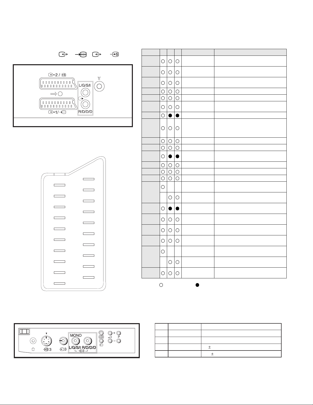
21 pin connector ( 1/ , 2 / )
21
20
19
18
17
16
15
14
13
12
11
10
9
8
7
6
5
4
3
2
1
Pin No 1 2 4 Signal Signal level
1 Audio output B
2
3
4 Ground (audio)
5 Ground (blue)
6 Audio input A
7 Blue input 0.7 +/- 3dB, 75 ohms positive
8 Function select
9 Ground (green)
10 Open
11 Green Green signal : 0.7 +/- 3dB, 75 ohms,
12 Open
13 Ground (red)
14 Ground (blanking)
15
_ (S signal Chroma
16 Blanking input
17 Ground (video
18 Ground (video
19 Video output 1V +/- 3dB, 75ohms, positive sync 0.3V
20
_ Video input
21 Common ground
Connected Not Connected (open) * at 20Hz - 20kHz
(right)
Audio output B
(right)
Audio output A
(left)
(left)
(AV control)
_ _ Red input 0.7 +/- 3dB, 75 ohms, positive
input)
(Ys signal)
output)
input)
_ _ Video input 1V +/- 3dB, 75ohms, positive sync 0.3V
Y (S signal)
(plug, shield)
Standard level : 0.5V rms
Output impedence : Less than 1kohm*
Standard level : 0.5V rms
Output impedence : More than 10kohm*
Standard level : 0.5V rms
Output impedence : Less than 1kohm*
Standard level : 0.5V rms
Output impedence : More than 10kohm*
High state (9.5-12V) : Part mode
Low state (0-2V) : TV mode
Input impedence : More than 10K ohms
Input capacitance : Less than 2nF
positive
0.3 +/- 3dB, 75 ohms, positive
High state (1-3V) Low state (0-0.4V)
Input impedence : 75 ohms
(-3+10dB)
(-3+10dB)
1V +/- 3dB, 75ohms, positive sync 0.3V
(-3+10dB)
Pin No.
1
2
3
4
Signal
Ground
Ground
Y (S signal) input
C (S signal) input
1V 3dB 75 ohm, positive Sync. 0.3V -3 + 10dB
0.3V 3dB 75 ohm, positive Sync.
Signal Level
4

TABLE OF CONTENTS
Section Title Page Section Title Page
Warning and Caution .....................3
FE-1A Self Diagnostic Softwa re .....................6
1. GENERAL
4. CIRCUIT ADJUSTMENTS
4-1. Electrical Adjustments .....................20
4-2. Test Mode 2 ............. .... ....23
Overview of Remote .....................7
Control Butt ons
Manually Tu nin g the TV .....................7
Fine Tuning Channels .....................8
Adjusting the Picture .....................8
Adjusting the Sound .....................9
Using the Sleep Time r .....................9
Viewing Teletext .....................10
Using Optional Equipment .....................10
Troublesho ot ing .....................11
Specification s .....................11
2. DISASSEMBLY
2-1. Rear Cover Removal .....................12
2-2. Chassis Assy Removal ................... ..1 2
2-3. Service Position .....................13
2-4. H Board Removal .....................13
2-5. S1 Board Removal .....................13
2-6. Picture Tube Removal .....................14
2-7. Removal and Replacement of .....................15
the Main - Bracket bottom plates
3. SET-UP ADJUSTMENTS
3-1. Beam Landing .....................16
3-2. Convergence .....................17
3-3. Focus .....................19
3-4. White Balance .....................19
5. DIAGRAMS
5-1. Block Diagram (1) .....................25
Block Diagram (2) .....................29
5-2. Circuit Board Location .....................32
5-3. Schematic Diagrams and
Printed Wiring Boards .....................32
* S1 Board .....................33
* F Board .....................34
* K Board .....................36
* H Board .....................37
* A Board .....................41
* VM Board .....................46
* C Board .....................50
5-4. Semiconductors .....................51
5-5. IC Blocks .....................53
6. EXPLODED VIEWS
6-1. Chassis .....................54
6-2. Picture Tube .....................56
7. ELECTRICAL PARTS LIST .....................57
CAUTION
SHORT CIRCUIT THE ANODE OF THE PICTURE TUBE AND THE
ANODE CAP TO THE METAL CHASSIS, CRT SHIELD, OR THE
CARBON PAINTED ON THE CRT, AFTER REMOVAL OF THE
ANODE CAP
WARNING !!
AN ISOLATING TRANSFORMER SHOULD BE USED DURING ANY
SERVICE WORK TO AVOID POSSIBLE SHOCK HAZARD DUE TO
LIVE CHASSI S. THE CHASSIS OF THIS RECEI VER IS DIRECTLY
CONNECTED TO THE POWER LINE.
SAFETY-RELATED COMPONENT WARNING !!
COMPONENTS IDENTIFIED BY SHADING AND MARKED ON
THE SCHEMATIC DIAGRAMS, EXPLODED VIEWS AND IN THE
P ARTS LIST ARE CRITICAL FOR SAFE OPERATION. REPLACE
THESE COMPONENTS WITH SONY PARTS WHOSE PAR T NUMBERS
APPEAR AS SHOWN IN THIS MANUAL OR IN SUPPLEMENTS
PUBLISHED BY SONY.
ATTENTION
APRES AVOIR DECONNECTE LE CAP DE’LANODE,
COURT-CIRCUITER L’ANODE DU TUBE CATHODIQUE ET
CELUI DE L’ANODE DU CAP AU CHASSIS METALLIQUE
DE L’A PPAREIL, OU AU COUCHE DE CARBONE PEINTE
SUR LE TUBE CATHODIQUE OU AU BLINDAGE DU TUBE
CATHODIQUE.
ATTENTION !!
AFIN D’EVITER TOUT RISQUE D’ELECTROCUTION PROV ENA NT
D’UN CHÁSSIS SOUS TENTION, UN TRANSFORMATEUR
D’ISOLEMENT DOIT ETRE UTILISÈ LORS DE TOUT DÈPANNAGE.
LE CHÁSSIS DE CE RÈCEPTEUR EST DIRECTMENT RACCORDÈ
Á L’ALI MENTATION SECTEUR.
ATTENTION AUX COMPOSANTS RELATIFS Á LA
SÈCURITÈ !!
LES COMPOSANTS IDENTIFIÈS PAR UNE TRAME ET PAR UNE
MARQUE SUR LES SCHÈMAS DE PRINCIPE, LES VUES
EXPLOSÈES ET LES LISTES DE PIECES SONT D’UNE IMPORTANCE
CRITIQUE POUR LA SÈCURITÈ DU FONCTIONNEMENT, NE LES
REMPLACER QUE PAR DES COMPSANTS SONY DONT LE NUMÈRO
DE PIÈCE EST INDIQUÈ DANS LE PRÈSENT MANUEL OU DANS
DES SUPPLÈMENTS PUBLIÈS PAR SONY.
5
StBy LED
ON ON ON
OFF OFF
(ON SCREEN
DISPLAY)
5
(DIGIT 5) (VOLUME -)
(TV)
i
+
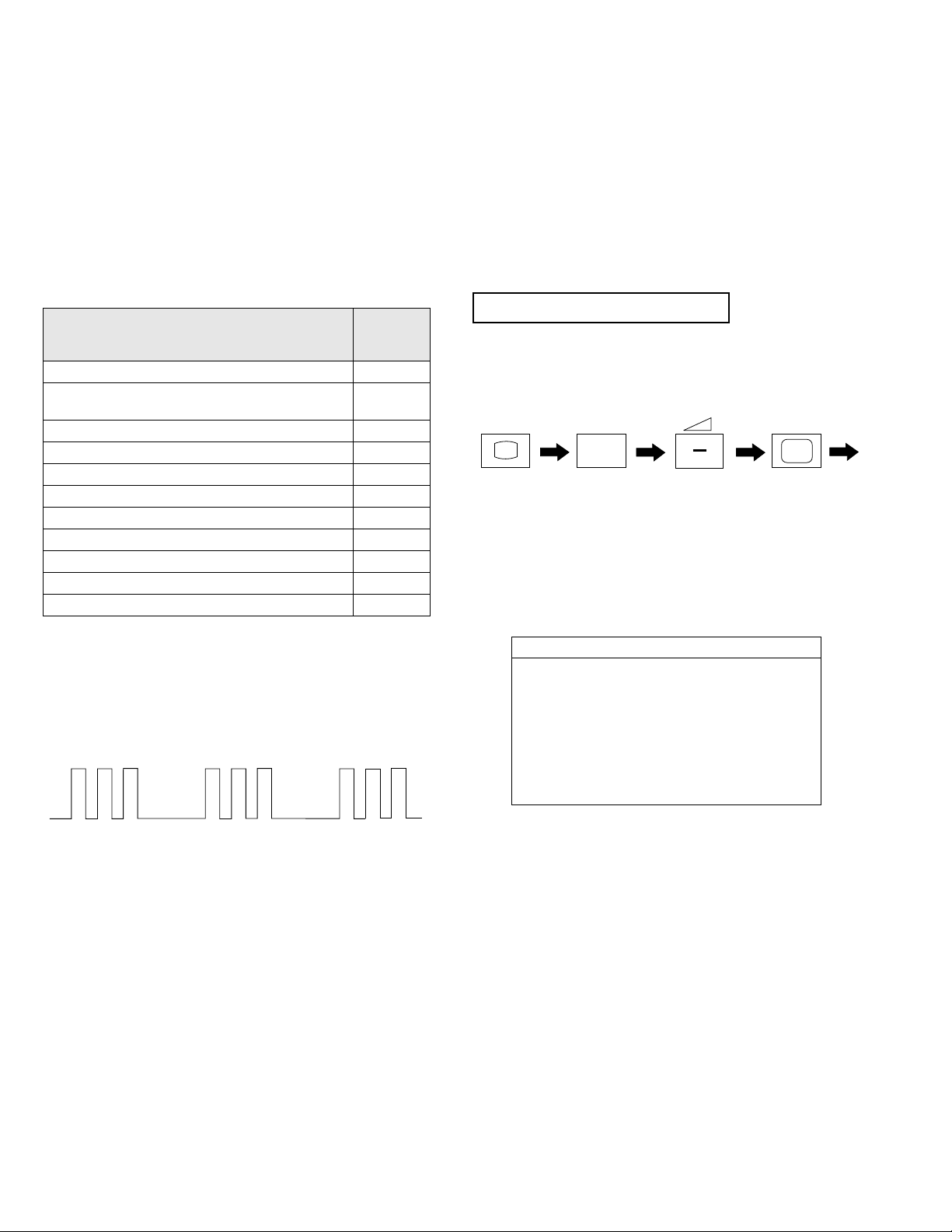
FE-1A SELF DIAGNOSTIC SOFTWARE
The identification of error s with in the F E- 1A ch a ssis i s trig ger ed in one of tw o ways :- 1: Busy or 2: Device failure to respond to IIC. In t he event
of one of these situati ons arising the so ftw are will first try to release the b u s if b usy (Fa ilure to do so will re port w ith contin uous flashing LED) an d
then communicate with each device in turn to establish if a de vice is f au lty. If a device is found to be faulty the rele vant device number will b e dis played through the LED (Series of flashes which must be counted) See Table 1., non fatal errors are reported using this method.
Each time the software detects an error i t is stored within the NVM. See Table 2.
Table 1
ERROR
No error 00
Not allowed (may be confused with Sircs response
flash!)
Protection circuit trip < ANY TIME > 02
Reserved 03
No vertical sync 04
AKB 05
IIC bus clock and/or data lines low at Power ON 06
NVM no IIC bus acknowledge at Power ON 07
Jungle controller no IIC acknowledge at Power ON 08
Tuner no acknowledge at Power ON 09
Sound processor no acknowledge at Power ON 10
Flash Timing Example : e.g. error number 3
LED
ERROR
COUNT
01
How to enter into Table 2
1. Turn on the main po w er switc h of the TV set and enter into the
‘Standby Mode’.
2. Press the following sequence of buttons on the Remote
Commander.
3. The following table will be displayed indicating the error
count.
Table 2
Error Times
2 -
3 4 5 6 7 8 9 10 -
Note: To clear the error count data press ‘80’ on the Remote
commander.
6
7
S
RM
887
PROGR
MENU
1
4
7
2
5
8
0
3
6
9
K
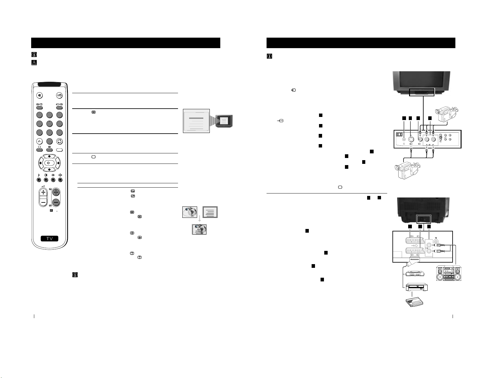
Getting Started - Overview
Getting Started - Overview
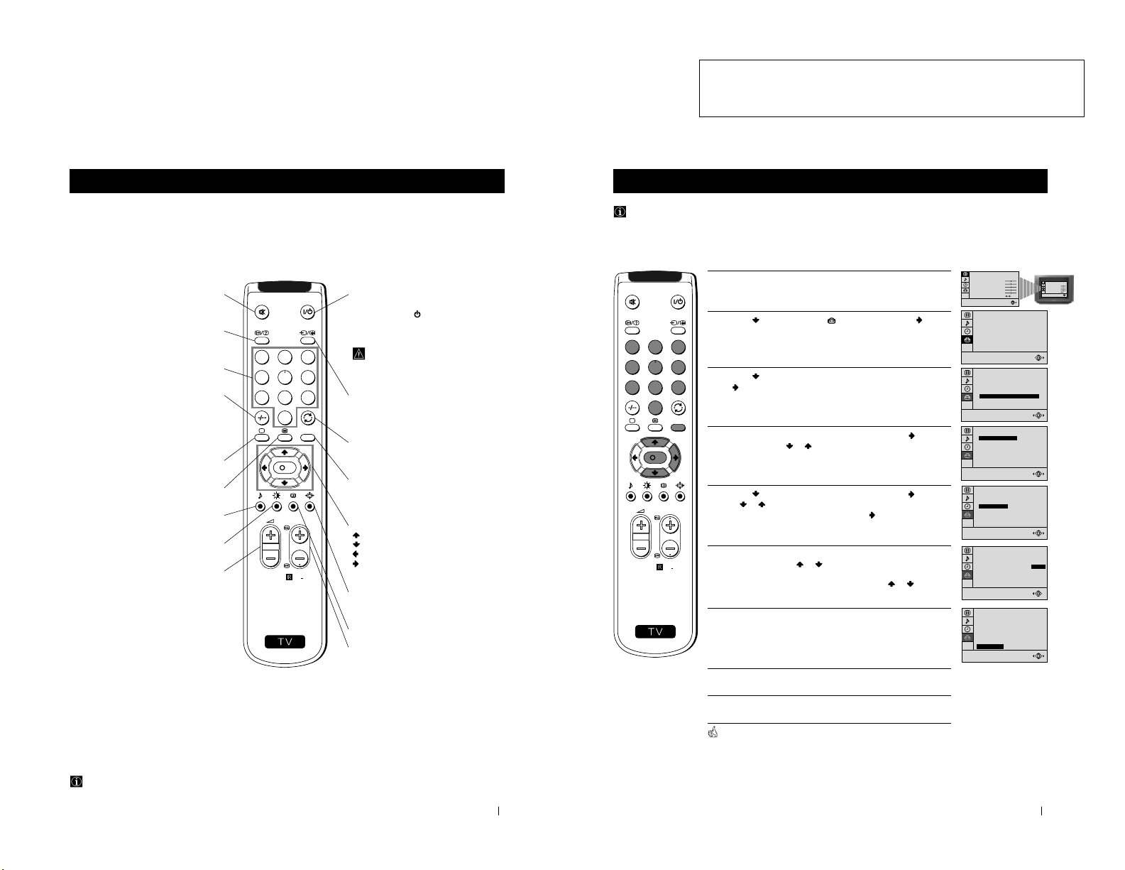
Overview of Remote Control Buttons
To Temporarily Switch Off TV
Press to temporarily switch off TV (the
standby indicator on TV lights up). Press
again to switch on TV from standby mode.
To save energy we recommend switching off
completely when TV is not in use.
After 15-30 minutes without a TV
signal and without any button being
pressed, the TV switches automatically
into standby mode.
Selecting Input source
Press repeatedly until the desired input
symbol of the source appears on the TV
screen.
Back to the channel last watched
Press to watch the last channel selected
(watched for at least 5 seconds).
Displaying the menu system
Press to display the menu on the TV screen.
Press again to remove the menu display
from the TV screen.
Menu selection
Scroll Up
Scroll Down
Previous menu or selection
Next menu or selection
OK Confirms your selection
Selecting Screen format
Press to view programmes in 16:9 mode.
Press again to return to 4:3 mode.
This button only works in Teletext mode.
Selecting channels
Press to select the next or previous channel.
Muting the Sound
Press to mute TV sound.
Press again to restore the sound.
Displaying On Screen Information
Press to display all on-screen indications.
Press again to cancel. +.--+++++-++++
Selecting channels
Press to select channels.
For double-digit programme numbers, e.g. 23,
press -/-- first, then the buttons 2 and 3.
If you enter an incorrect first digit, this should
be corrected by entering another digit (0-9)
and then selecting -/-- button again to enter
the programme number of your choice.
+++++++++++++++...
Selecting TV mode
Press to switch off Teletext or video input.
+++++++++++++++++...
Selecting Teletext
Press to switch on Teletext.
Selecting Sound mode
Press to change the sound mode.
+++++++++++++++++...
Selecting Picture mode
Press to change the picture mode.
+++++++++++++++++...
Adjusting TV Volume
Press to adjust the volume of the TV.
Besides TV functions, all coloured buttons are also used for Teletext operation. For more details, please refer to the
"Teletext" section of this instruction manual.
13
Advanced Operation - Advanced Presetting
Advanced Operation - Advanced Presetting
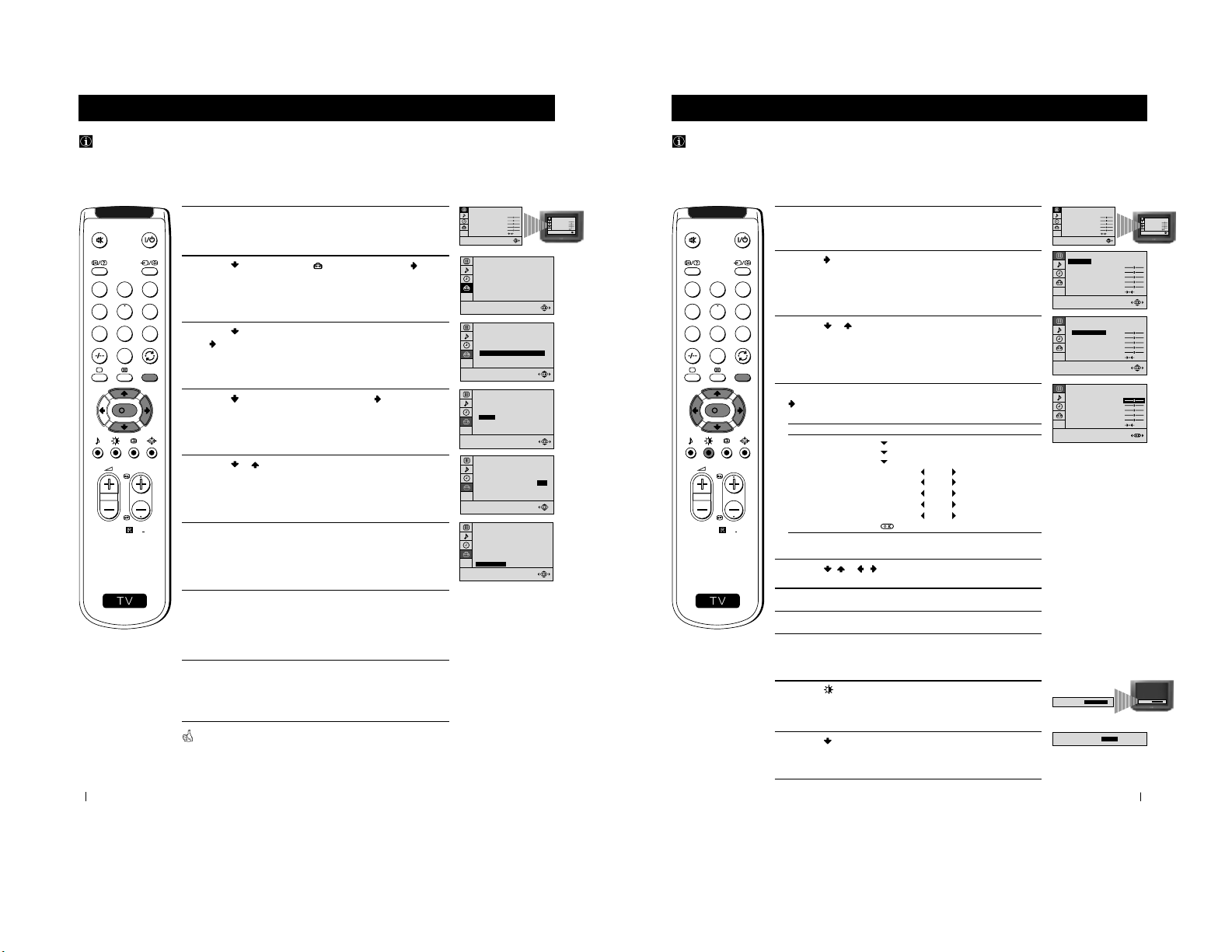
Manually Tuning the TV
Use this function to preset channels or a video input source one by one to the programme order of your choice.
1 Press the MENU button on the remote control to display the menu
on the TV screen.
2 Press the button to select the symbol, then press the button
to enter to the SET UP menu.
3 Press the button to select MANUAL PROGRAMME, then press
the button.
4 With the cursor highlighting PROGRAMME, press the button
and then, press the
or button to select on which programme
number you want to preset a channel. Press the OK button.
5 Press the button to select CHANNEL, then press the button.
Press
or button to select the channel tuning, "C" for terrestrial
channels or "S" for cable channels. Press the button.
6 Press the number buttons to enter the channel number of the TV
Broadcast or press the or button to search for the next
available channel.
If you do not wish to store this channel, press the
or button to
continue searching for the desired channel.
7 If this is the desired channel you wish to store, press the OK button
and then, with the cursor highlighting CONFIRM, press the OK
button again.
8 Repeat steps 4 to 7 if you wish to store more channels.
9 Press the MENU button to exit and return to the normal TV screen.
Your TV is now ready for use.
PICTURE CONTROL
CONTRAST
BRIGHTNESS
COLOUR
SHARPNESS
HUE
RESET
MODE: PERSONAL
PICTURE CONTROL
CONTRAST
BRIGHTNESS
COLOUR
SHARPNESS
HUE
RESET
MODE: PERSONAL
0
SET UP
PICTURE ROTATION:
LANGUAGE: ENGLISH
AUTO PROGRAMME
PROGRAMME SORTING
MANUAL PROGRAMME
0
SET UP
PICTURE ROTATION:
LANGUAGE: ENGLISH
AUTO PROGRAMME
PROGRAMME SORTING
MANUAL PROGRAMME
01
I
C 21
ON
NO
OFF
SET UP:
MANUAL PROGRAMME
CONFIRM
PROGRAMME:
SYSTEM:
CHANNEL:
AFT:
SKIP:
DECODER:
01
I
C 21
ON
NO
OFF
SET UP:
MANUAL PROGRAMME
CONFIRM
PROGRAMME:
SYSTEM:
CHANNEL:
AFT:
SKIP:
DECODER:
SET UP:
MANUAL PROGRAMME
CONFIRM
PROGRAMME:
SYSTEM:
CHANNEL:
AFT:
SKIP:
DECODER:
01
I
C 21
ON
NO
OFF
01
I
C 21
ON
NO
OFF
SET UP:
MANUAL PROGRAMME
CONFIRM
PROGRAMME:
SYSTEM:
CHANNEL:
AFT:
SKIP:
DECODER:
S
RM
887
PROGR
MENU
1
4
7
2
5
8
0
3
6
9
K
7
The operating instructions mentioned here are partial abstracts
SECTION 1 GENERAL
from the Operating Manual. The page numbers of the Operating
Instruction Manual remain as in the manual.
14
Advanced Operation - Advanced Presetting
Advanced Operation - Advanced Presetting
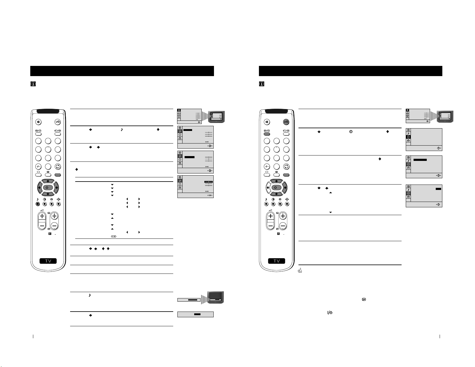
Fine Tuning Channels
Normally, the automatic fine tuning (AFT) function is operating. If the picture is distorted, however, you can manually fine
tune the TV to obtain a better picture reception.
1 Select the channel (TV Broadcast) you wish to fine tune, then press
the MENU button on the remote control to display the menu on the
TV screen.
2 Press the button to select the symbol, then press the button
to enter to the SET UP menu.
3 Press the button to select MANUAL PROGRAMME, then press
the
button.
4 Press the button to select AFT , then press the button.
5 Press the or button to adjust the fine tuning (-15 to +15), then
press the OK button.
6 With the cursor highlighting CONFIRM, press the OK button to
store.
7 Press the MENU button to exit and return to the normal TV screen.
8 Repeat steps 1 to 7 to fine tune other channels.
Your TV is now ready for use.
PICTURE CONTROL
CONTRAST
BRIGHTNESS
COLOUR
SHARPNESS
HUE
RESET
MODE: PERSONAL
PICTURE CONTROL
CONTRAST
BRIGHTNESS
COLOUR
SHARPNESS
HUE
RESET
MODE: PERSONAL
0
SET UP
PICTURE ROTATION:
LANGUAGE: ENGLISH
AUTO PROGRAMME
PROGRAMME SORTING
MANUAL PROGRAMME
0
SET UP
PICTURE ROTATION:
LANGUAGE: ENGLISH
AUTO PROGRAMME
PROGRAMME SORTING
MANUAL PROGRAMME
SET UP:
MANUAL PROGRAMME
CONFIRM
PROGRAMME:
SYSTEM:
CHANNEL:
AFT:
SKIP:
DECODER:
01
I
C 21
+2
NO
OFF
S
RM
887
PROGR
MENU
1
4
7
2
5
8
0
3
6
9
K
01
I
C 21
ON
NO
OFF
SET UP:
MANUAL PROGRAMME
CONFIRM
PROGRAMME:
SYSTEM:
CHANNEL:
AFT:
SKIP:
DECODER:
01
I
C 21
+2
NO
OFF
SET UP:
MANUAL PROGRAMME
CONFIRM
PROGRAMME:
SYSTEM:
CHANNEL:
AFT:
SKIP:
DECODER:
17
1 Press the MENU button on the remote control to display the menu
on the TV screen.
2 Press the button to enter to the PICTURE CONTROL menu.
3 Press the or button to select the item you wish to change.
4 With the cursor highlighting the item you wish to change, press the
button.
(Refer to the table below for the effect of each control).
5 Press the / or / button to alter the selected item, then press
the OK button to store the new adjustment.
6 Repeat steps 3 to 5 to alter the other items.
7 Press the MENU button to exit and return to the normal TV screen.
PICTURE CONTROL OPERATION / EFFECT
MODE PERSONAL (for individual settings)
LIVE (for live broadcast programmes)
MOVIE (for films)
CONTRAST Less
More
BRIGHTNESS
* Darker Brighter
COLOUR* Less More
SHARPNESS* Softer Sharper
HUE
** Greenish Reddish
RESET Resets picture to the factory preset levels.
* Can be only altered if PERSONAL MODE is selected.
** Only avalaible for NTSC colour signal (e.g: US video tapes).
Advanced Operation - Advanced TV Operation
Adjusting the Picture
Although the picture is adjusted at the factory, you can modify it to suit your own taste.
Changing Picture Mode Quickly
1 Press the button on the remote control to directly access the
PICTURE MODE .
2 Press the button to select your desired picture mode
(PERSONAL, LIVE or MOVIE ), then press the OK button.
Advanced Operation - Advanced TV Operation
PICTURE CONTROL
CONTRAST
BRIGHTNESS
COLOUR
SHARPNESS
HUE
RESET
MODE: PERSONAL
PICTURE CONTROL
CONTRAST
BRIGHTNESS
COLOUR
SHARPNESS
HUE
RESET
MODE: PERSONAL
PICTURE CONTROL
CONTRAST
BRIGHTNESS
COLOUR
SHARPNESS
HUE
RESET
MODE: PERSONAL
PICTURE CONTROL
MODE: PERSONAL
CONTRAST
BRIGHTNESS
COLOUR
SHARPNESS
HUE
RESET
PICTURE CONTROL
MODE: PERSONAL
CONTRAST
BRIGHTNESS
COLOUR
SHARPNESS
HUE
RESET
PICTURE MODE:
PERSONAL
PICTURE MODE:
PICTURE MODE:
LIVE
PICTURE MODE:
PERSONAL
S
RM
887
PROGR
MENU
1
4
7
2
5
8
0
3
6
9
K
8
18
1 Press the MENU button on the remote control to display the menu
on the TV screen.
2 Press the button to select the symbol, then press the button
to enter to the SOUND CONTROL menu.
3 Press the or button to select the item you wish to change.
4 With the cursor highlighting the item you wish to change, press the
button.
(Refer to the table below for the effect of each control).
5 Press the / or / button to alter the selected item, then press
the OK button to store the new adjustment.
6 Repeat steps 3 to 5 to alter the other items.
7 Press the MENU button to exit and return to the normal TV screen.
SOUND CONTROL OPERATION / EFFECT
MODE PERSONAL (for individual settings)
JAZZ
POP
ROCK
TREBLE
* Less More
BASS
* Less More
BALANCE Left
Right
DUAL SOUND • For a stereo broadcast:
MONO
STEREO
• For a bilingual broadcast:
A for channel 1
B for channel 2
DSP (Digital sound Processor) ON OFF
RESET Resets sound to the factory preset levels.
* Can be only altered if PERSONAL MODE is selected.
Advanced Operation - Advanced TV Operation
Adjusting the Sound
Although the sound is adjusted at the factory, you can modify it to suit your own taste.
Changing Sound Mode Quickly
1 Press the button on the remote control to access directly to the
SOUND MODE .
2 Press the button to select your desired sound mode
(PERSONAL, JAZZ, POP or ROCK ), then press the OK button.
Advanced Operation - Advanced TV Operation
PICTURE CONTROL
CONTRAST
BRIGHTNESS
COLOUR
SHARPNESS
HUE
RESET
MODE: PERSONAL
PICTURE CONTROL
CONTRAST
BRIGHTNESS
COLOUR
SHARPNESS
HUE
RESET
MODE: PERSONAL
STEREO
ON
SOUND CONTROL
TREBLE
BASS
BALANCE
DUAL SOUND:
DSP:
RESET
MODE: PERSONAL
STEREO
ON
SOUND CONTROL
MODE: PERSONAL
TREBLE
BASS
BALANCE
DUAL SOUND:
DSP:
RESET
STEREO
ON
SOUND CONTROL
MODE: PERSONAL
TREBLE
BASS
BALANCE
DUAL SOUND:
DSP:
RESET
SOUND MODE:
PERSONAL
SOUND MODE:
PERSONAL
SOUND MODE:
POP
S
RM
887
PROGR
MENU
1
4
7
2
5
8
0
3
6
9
K
19
Advanced Operation - Advanced TV Operation
Using the Sleep Timer
You can select a time period for the TV to switch itself automatically into the standby mode.
1 Press the MENU button on the remote control to display the menu
on the TV screen.
2 Press the button to select the symbol, then press the button
to enter to the TIMER menu.
3 With the cursor highlighting OFF TIMER, press the button.
4 Press the or button to set the time period delay
OFF
0:15 min.
0:30 min.
...
...
4:00 hours
5 Press the OK button.
6 Press the MENU button to exit and return to the normal TV screen.
One minute before the TV switches into standby mode, the time remaining
is displayed on the TV screen automatically.
Notes: • When watching the TV, press the
button to display the
time remaining.
• To return to normal operation from standby mode,
press the button.
Advanced Operation - Advanced TV Operation
PICTURE CONTROL
CONTRAST
BRIGHTNESS
COLOUR
SHARPNESS
HUE
RESET
MODE: PERSONAL
PICTURE CONTROL
CONTRAST
BRIGHTNESS
COLOUR
SHARPNESS
HUE
RESET
MODE: PERSONAL
TIMER
OFF TIMER:
0:15
OFF
TIMER
OFF TIMER:
OFF
TIMER
OFF TIMER:
S
RM
887
PROGR
MENU
1
4
7
2
5
8
0
3
6
9
K
9
20
Teletext
Teletext
Viewing Teletext
Using Fastext
Fastext lets you access pages with one button stroke.
When Fastext is broadcast, a colour coded menu appears at the
bottom of the teletext page. Press the colour button (red, green,
yellow or blue) on the remote control to access the corresponding
page.
Index
TELETEXTTELETEXT
Programme
News
Sport
Weather
25
153
101
98
Index
TELETEXTTELETEXT
Programme
News
Sport
Weather
25
153
101
98
Index
TELETEXTTELETEXT
Programme
News
Sport
Weather
25
153
101
98
Index
TELETEXTTELETEXT
Programme
News
Sport
Weather
25
153
101
98
Selecting Teletext
1 Select the TV channel which carries the teletext service you wish to
view.
2 Press the button on the remote control to switch on the teletext.
3 Input three digits for the page number, using the numbered buttons
on the remote control. (if you have made a mistake, type in any
three digits and then, re-enter the correct page number).
4 Press the button to switch off teletext.
Using other Teletext functions
TO PRESS THE BUTTON
Access the next or preceding page
for next page or
for the preceding page
Superimpose teletext on to the TV
Press again to cancel teletext
mode.
Freeze a teletext page
Press again to cancel the
freeze.
Reveal concealed information
(e.g: answer to a quiz) Press again to cancel.
Teletext is an information service transmitted by most TV stations.
Make sure to use a TV channel with a strong signal, otherwise teletext errors may occur.
S
RM
887
PROGR
MENU
1
4
7
2
5
8
0
3
6
9
K
21
1
1
22
L/G/S/I
R/D/D/D
2 /
1/
s
E
F
G
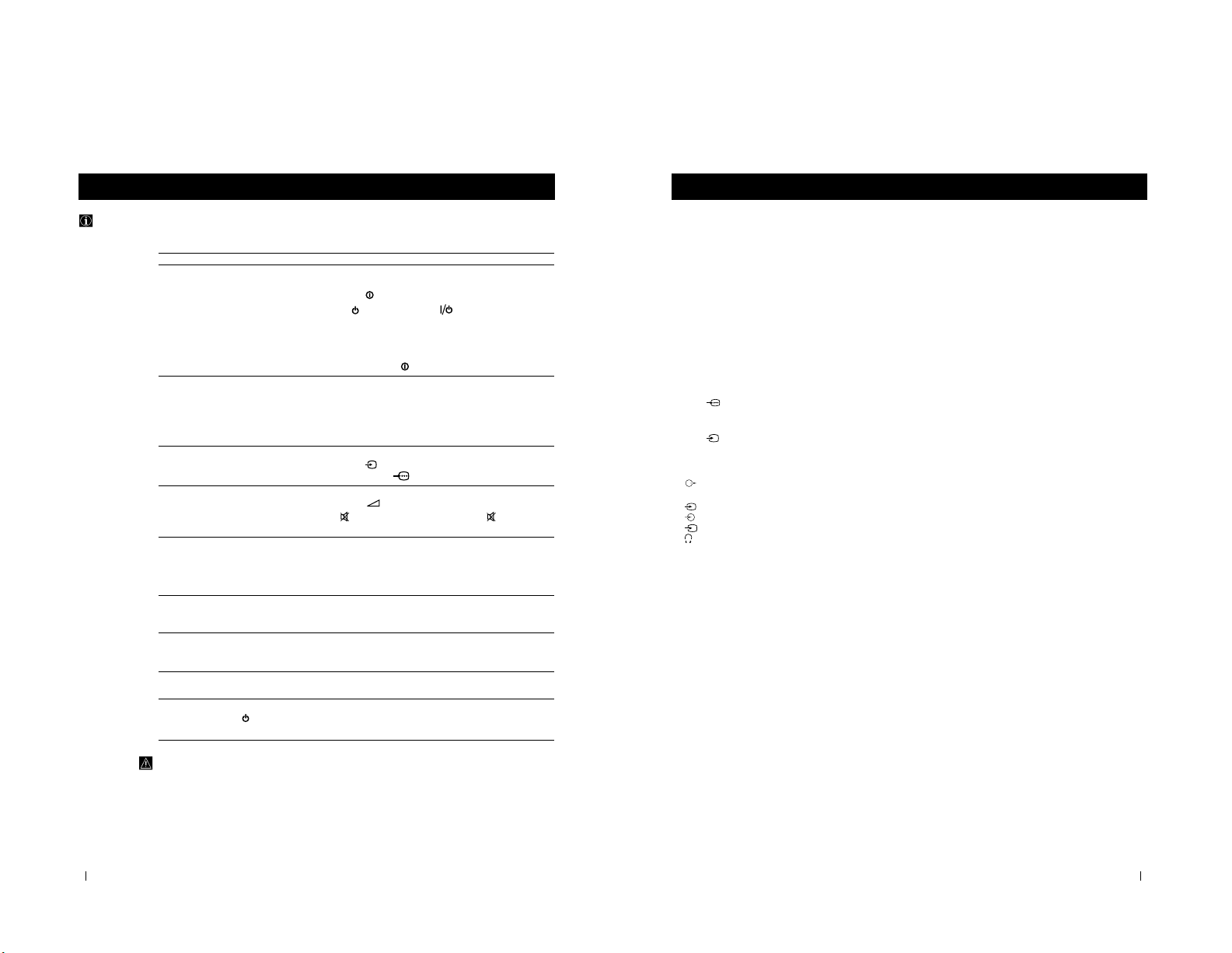
Front of TV
8mm/Hi8
camcorder
VCR
“PlayStation”
*
Hi-Fi
Rear of TV
S-VHS/Hi8
camcorder
Decoder
Optional Connections
You can connect optional audio or video equipment to your TV, such as a VCR, a camcorder or a video game as shown
below.
Using Optional Equipment
MONO
L/G/S/I R/D/D/D
+
P
_
L/G/S/I R/D/D/D
s
3
3
3
L/G/S/I R/D/D/D
Optional Connections
Select and View the Input Signal
1
Connect your equipment to the designated TV socket.
2 Press
the
button repeatedly on your remote control until the correct
input symbol appears on the TV screen.
Symbol Input signals
k • Audio/video input signal through the Euro AV
connector
F
• RGB input signal through the Euro AV
connector
F
K
• Audio/video input signal through the Euro AV
connector
E
q
• S video input signal through the Euro AV
connector
E
K
• Video input signal through the phono socket
C
and
Audio input signal through
D
q
• S video input signal through the socket
B
and
Audio input signal through D.
3 Switch on the connected equipment.
4 To return to normal TV picture, press the button on the remote control.
Note: To avoid picture distortion, do not connect equipment to the B and
E
connectors
at the same time.
Additional Information
Connecting a VCR
Plug in VCR to the socket
F
on the rear of the TV set.
We recommend you tune in the VCR signal to TV programme number ‘0’ using
the section “Manually Tuning the TV“ of this instruction manual.
Connecting Headphones
Plug in your headphones to the socket
A
on the front of the TV set.
Connecting Decoders
Plug in decoders to the socket
F
on the rear of the TV.
Connecting to External Audio Equipment
Plug in your Hi-Fi equipment to the
G
sockets on the rear of the TV if you wish
to amplify the audio output from the TV.
* “PlayStation” is a product of Sony Computer Entertainment, Inc.
* “PlayStation” is a trademark of Sony Computer Entertainment, Inc.
3
2
3
B
C
D
A
10
24
Additional Information
Troubleshooting
Here are some simple solutions to the problems which may affect the picture and sound.
Problem Solution
No picture (screen is dark), no sound • Plug the TV in.
• Press the
button on the front of TV.
• If the
indicator is on, press button or a
programme number button on the remote control.
• Check the aerial connection.
• Check that the selected video source is on.
• Turn the TV off for 3 or 4 seconds and then turn it
on again using the
button on the front of the TV.
Poor or no picture (screen is dark), • Using the MENU system, select the Picture Adjustment
but good sound display.
Adjust the brightness, picture and colour balance levels.
• From the Picture Adjustment display select RESET to return
to the factory settings.
Poor picture quality when watching a • Press the button repeatedly on the remote control until
RGB video source. the RGB symbol is displayed on the screen.
Good picture, no sound • Press the +/– button on the remote control.
• If
is displayed on the screen, press the button on the
remote control.
No colour on colour programmes • Using the MENU system, select the Picture Adjustment
display. Adjust the colour balance.
• From the Picture Adjustment display select RESET to return
to the factory settings.
Distorted picture when changing • Turn off any equipment connected to the 21 pin Euro
programmes or selecting teletext connector on the rear of the TV.
Noisy picture when viewing TV • Adjust Fine Tuning to obtain better picture reception.
channel
Remote control does not function • Replace the batteries.
The standby indicator on the TV • Contact to your nearest Sony service centre.
flashes.
• If you continue to have these problems, have your TV serviced by qualified personnel.
• NEVER open the casing yourself.
Additional Information
25
Additional Information
Additional Information
Specifications
TV system
I
Colour system
PAL
NTSC 3.58, 4.43 (only Video In)
Channel coverage
UHF: B21-B69
Picture tube
Flat Display Trinitron
Approx. 72 cm (29 inches) (Approx. 68 cm picture
measured diagonally), 104° deflection
Rear Terminals
:1/
21-pin Euro connector (CENELEC
standard) including audio/video input,
RGB input, TV audio/video output
:2/
s
21-pin Euro connector (CENELEC
standard) including audio/video input,
S-video input, monitor audio/video
output
Audio outputs - phono jacks
Front Terminals
2
video input - phono jack
2
audio inputs - phono jacks
s
S video input - 4 pin DIN
Headphones jack - minijack stereo
Sound output
2x7 W + 1x15 W (RMS)
Power consumption
150 W
Standby Power consumption
0.5 W
Dimensions (w x h x d)
Approx. 746 x 569 x 516 mm
Weight
Approx. 47.5 kg
Accessories supplied
1 Remote Control (RM-887)
2 Batteries (IEC designated)
Other features
TELETEXT, Fastext, TOPtext
NICAM Stereo
Sleep Timer
Smartlink
Design and specifications are subject to change without notice.
3
3
3
11
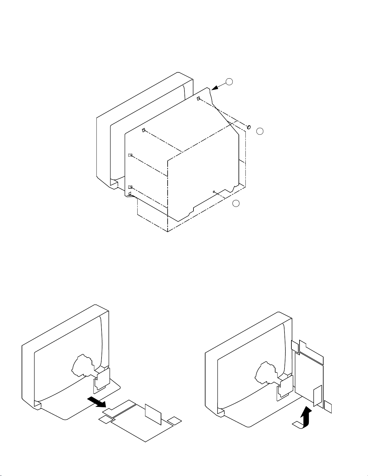
2-1. REAR COVER REMOVAL
SECTION 2
DISASSEMBLY
3 Rear Cover
2 6 Screws BTV 4x16
2-2. CHASSIS ASSY REMOVAL
1 1 Screw BTV 4x16
2-3. SERVICE POSITION
12
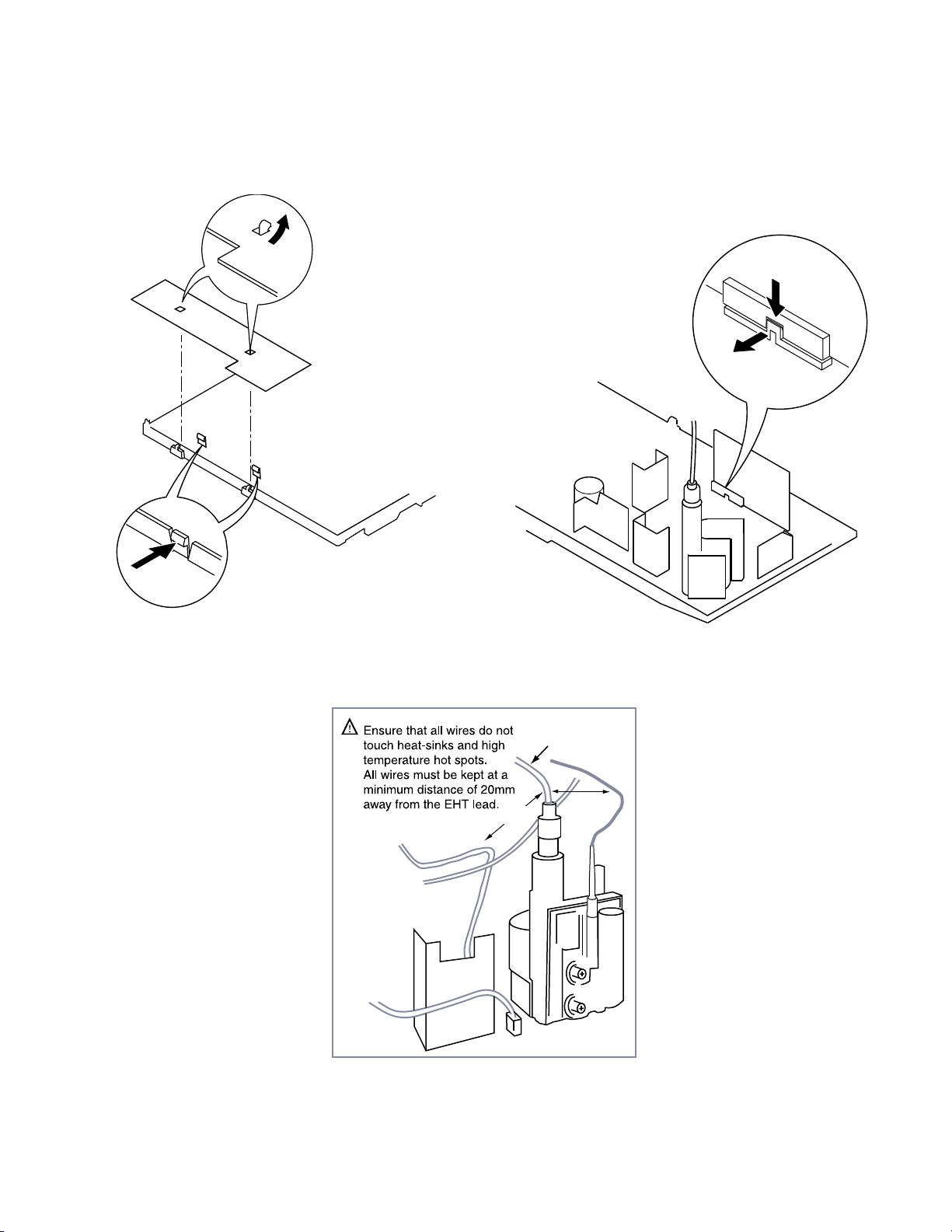
>20mm
>20mm
EHT Lead
2-4. H BOARD REMOVAL 2-5. S1 BOARD REMOVAL
Release the clip indicated
To release, push the claws in the direction
of the arrow as indicated.
13
Anode button
a
* REMOVING PROCEDURES.
Turn up one side of the rubber cap in
the direction indicated by the arrow a
1
2 Using a thumb pull up the rubber cap
firmly in the direction indicated by the
arrow b
3 When one side of the rubber cap is
separated from the anode button, the
anode-cap can be removed by turning
up the rubber cap and pulling it up in
the direction of the arrow c
b
b
c
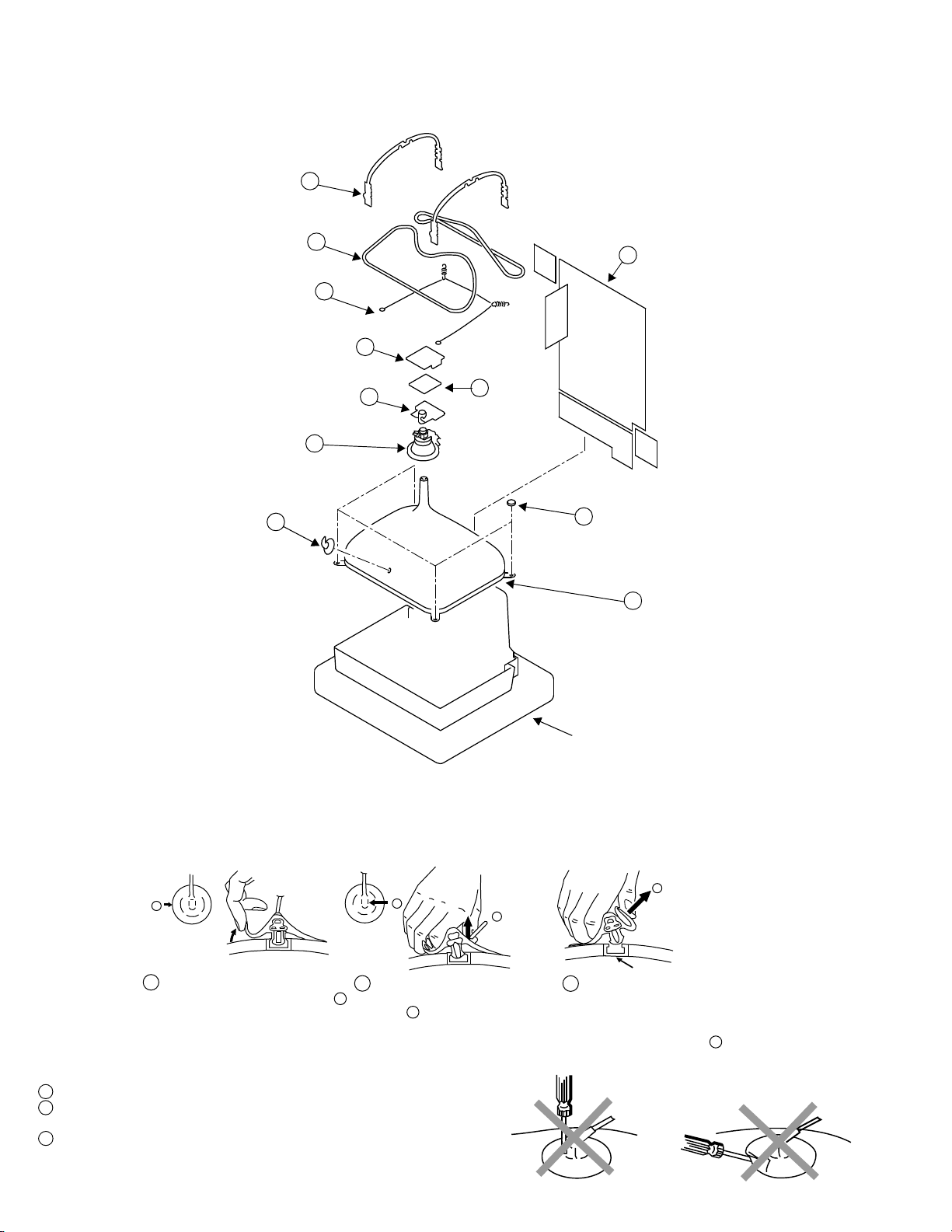
2-6. PICTURE TUBE REMOVAL
Two DGC holders 7
Degaussing coils 8
Spring Extension 9
C Board
Neck assy 5
Deflection yoke
Anode cap 1
2 Chassis assy
3
4
VM Board
6
10 Four PT screws (M)
11 Picture tube
Cushion
• REMOVAL OF ANODE-CAP
Note : Short circuit the anode of t he picture tube and the anode cap to the metal chassis, CRT shield or carbon paint on th e CRT, after removing the anode.
• HOW TO HANDLE THE ANODE-CAP
1 To prevent damaging the surface of the a node -cap do not use sharp materials.
2 Do not apply too great a pressure on the rubber, as this may cause damage to the
anode connector.
3 A metal fitting ca lled a shatter hook terminal is fitted inside the rub ber cap.
Do not turn the rubber foot over excessively this may cause damage if the shatter
hook sticks out.
14
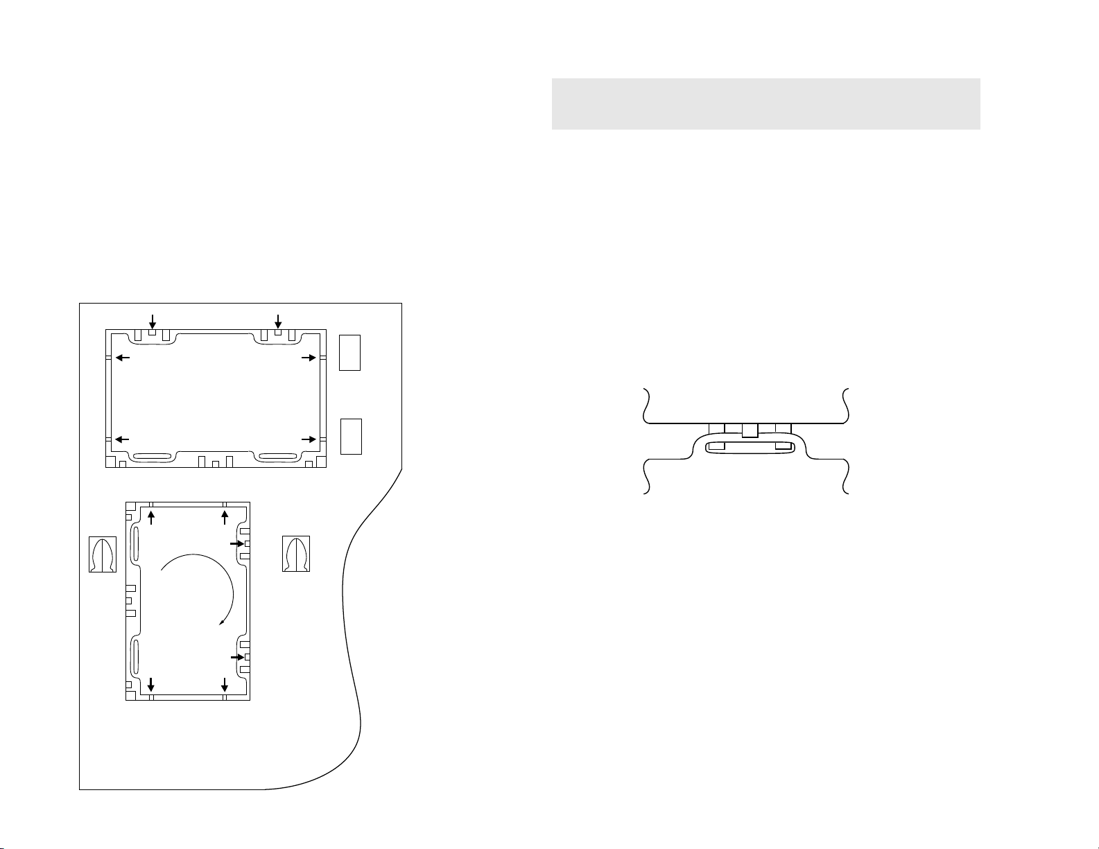
Tab
Catch
CatchCatch
Catch
Catch
Tab
Tab
Tab
Tab
Refitting
Gate
Gate
Gate
Gate
GateGate
Gate Gate
REMOVAL AND REPLACEMENT OF THE MAIN-BRACKET
BOTTOM PLATES.
For safety reasons, on no account should the plates be
£
removed and not refitted after servicing.
(1) REMOVING THE PLATES
In the event of servicing being required to the solder side of the A Board printed
wiring board, the bottom plates fitted to the main chassis bracket r equ ire to be
removed.
This is performed by cutting the gates with a sharp wire cutter at the locations
shown and indicated by arrows.
Note :There are 2 plates fitted to the main bracket and secured by 4 gates.
Only remove the necessary plate to gain access to the printed wiring board.
15
(2) REFITTING THE PLATES
Because the plates differ in size it is important th at the corr ect pla tes are ref it ted in
their original location.
Please note that the plates need to be rotated 180 degrees from the cut position to
allow the tabs to be fitted in the catch positions.
SECTION 3
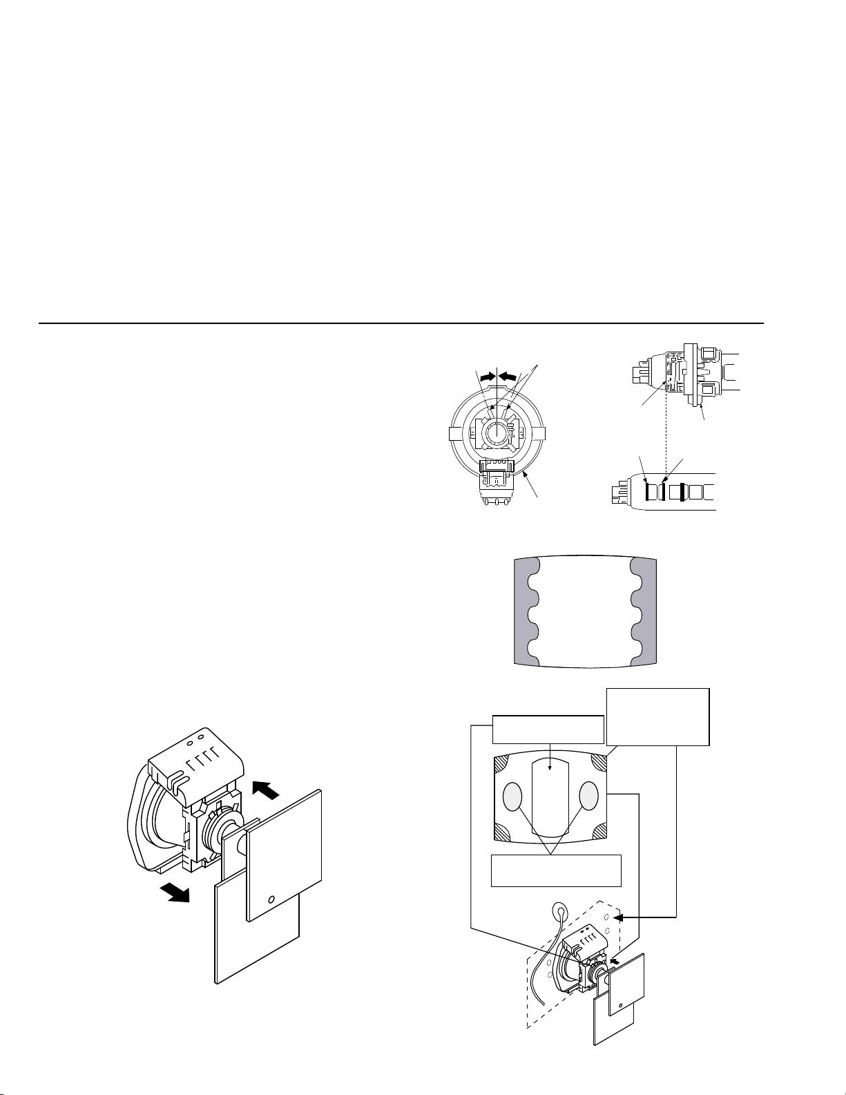
Purity control corrects
this area
Disk magnets or
rotatable disk
magnets correct
these areas (a-d)
Deflection yoke positioning
corrects these areas
GREEN
BLUE
RED
Purity control
Neck Assy
A buckle
G2
G1
Deflection yolk
SET-UP ADJUSTMENTS
• When complete readjustment is necessary or a new
picture tube is installed, carry out the following
adjustments.
• Unless there are specific instructions to the contrary,
carry out these adjustments with the rated power supply.
• Unless there are specific instructions to the contrary, set the
controls and switches to the following settings :
Contrast ............... 80% [or remote control normal]
Brightness ............... 50%
Preparation:
1. In order to reduce the influence of geomagnetism on the set’s
picture tube, face it in an easterly or westerly direction.
2. Switch on the set’s power and degauss with the
degausser.
3-1. BEAM LANDING
1. Input an all white signal from the pattern generator.
Set the Contrast and Brightness to normal.
2. Set the pattern generator r as ter signal to Red.
3. Move the deflection yoke forward and adjust with the purity
control so that the Red is at the centre and the Blue and Green
take up equally sized areas on each side of the screen.
[See Fig.3-1 - 3-3].
4. Move the deflection yoke forw ard and adjust so that the entire
screen becomes Red. [See Fig.3 -1]
5. Switch the raster signal to Blue, then to Green and verify the
condition.
6. When the pos ition of the deflection yoke has been determ ined,
fasten the deflection yoke with the screws.
7. If the beam does not land cor r ectly in all the corners, use a
magnet to correct it. [See Fig.3-4]
Carry out the following adjustments in this order :
3-1. Beam Landing
3-2. Convergence
3-3. Focus
3-4. White Balance
Note : Test equipment required
1. Color bar/pattern generator.
2. Degausser.
3. Oscilloscope.
4. Digital multimeter.
5. DC Power supply.
Fig. 3-2
Fig. 3-3
Fig. 3-1
Fig. 3-4
16

R
G
B
Center dot
RG B
H.STAT
V. STAT Magnet
RV702
RV701
SCREEN
H. STAT
3-2. CONVERGENCE
Preparation:
• Before starting this adjustment, adjust the focus, horizontal
size and vertical size.
• Minimize the Brightness setting.
• Input a dot pattern from the pattern generator.
(1) Horizontal and vertical static convergence
• Tilt the V.STAT magnet and adjust the static convergence
by opening or clo s ing the V.STAT m a gnet.
4. If the V.STAT magnet is moved in the direction of the a
and b arrows, the Red, Green and Blue points move as
indicated below.
1. [Moving horizontally], adjust the H.STAT control so that the
Red, Green and Blue points are o n t op of each other at the
centre of the screen.
2. [Moving vertically], adjust the V.STAT magnet so that the
Red, Green and Blue points are o n t op of each other at the
centre of the screen.
3. If the H.STAT variable resistor is unable to bring the Red,
Green and Blue points together at the centre of the screen,
adjust the horizontal convergence with the H.STAT variable
resistor and the V.STAT magnet in the manner indicated belo w.
[In this case, the H.STAT variable resistor and the V.STAT
magnet influence each other].
17
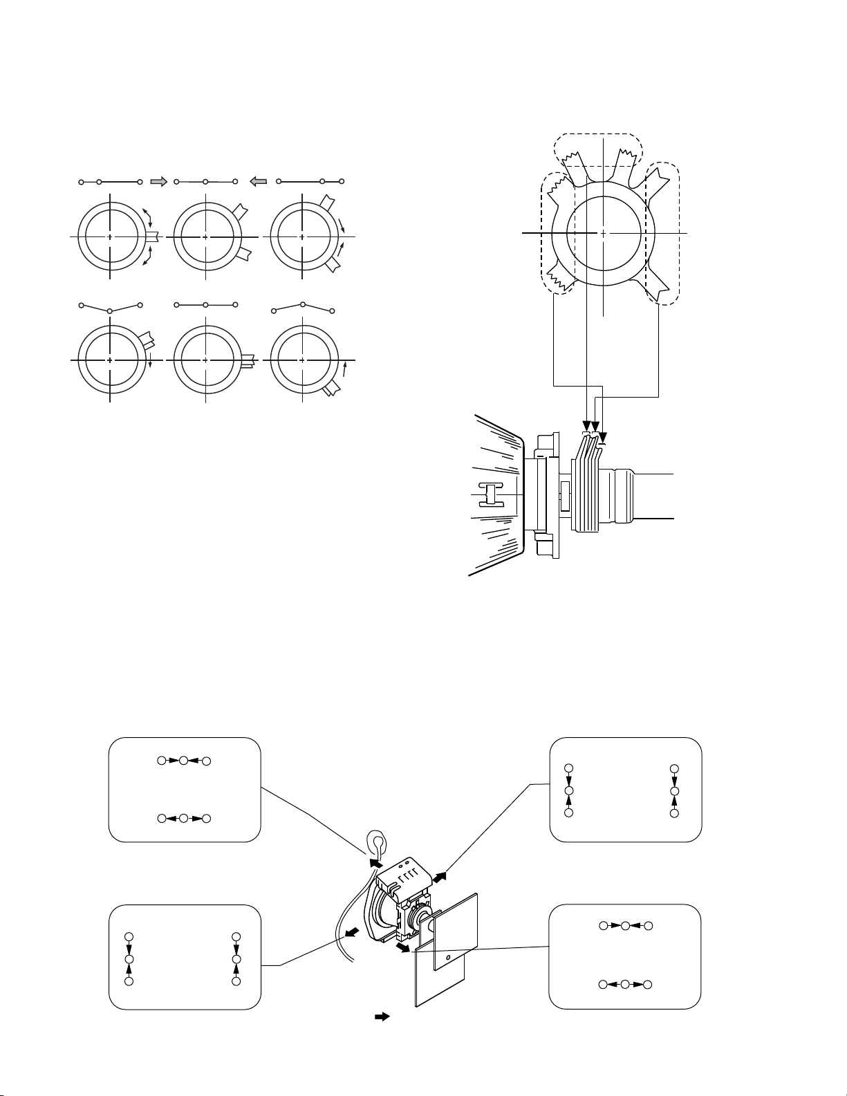
BMC (Hexapole)
V.STAT
Purity
RG B R G B R G B
RGBR
G
B
R
G
B
RG
B
B
G
R
RG
B
BG
R
B
G
R
R
G
B
R
G
B
B
G
R
Tilt Direction
• Operation of the BMC (Hexapole) magnet.
• The respective dot position resulting from moving each
magnet interact, so be sure to perform adjustment whilst
tracking.
Use the H.STAT VR to adjust the Red, Green and Blue dots
so that they coincide at the centre of the screen
(by moving the dots in the horizontal direction).
(2) Dynamic convergence adjustment.
Preparation:
• Before starting this adjustment, adjust the horizontal and
vertical static convergence.
1. Remove the deflection yoke spacer.
2. Tilt the deflection yoke as indicated in the figure below and
optimize the convergence.
3. Re-install the deflection yoke spacer.
Note : This adjustment will affect the geometry of the
display, therefore adjust to obtain the optimum
setting.
18
 Loading...