

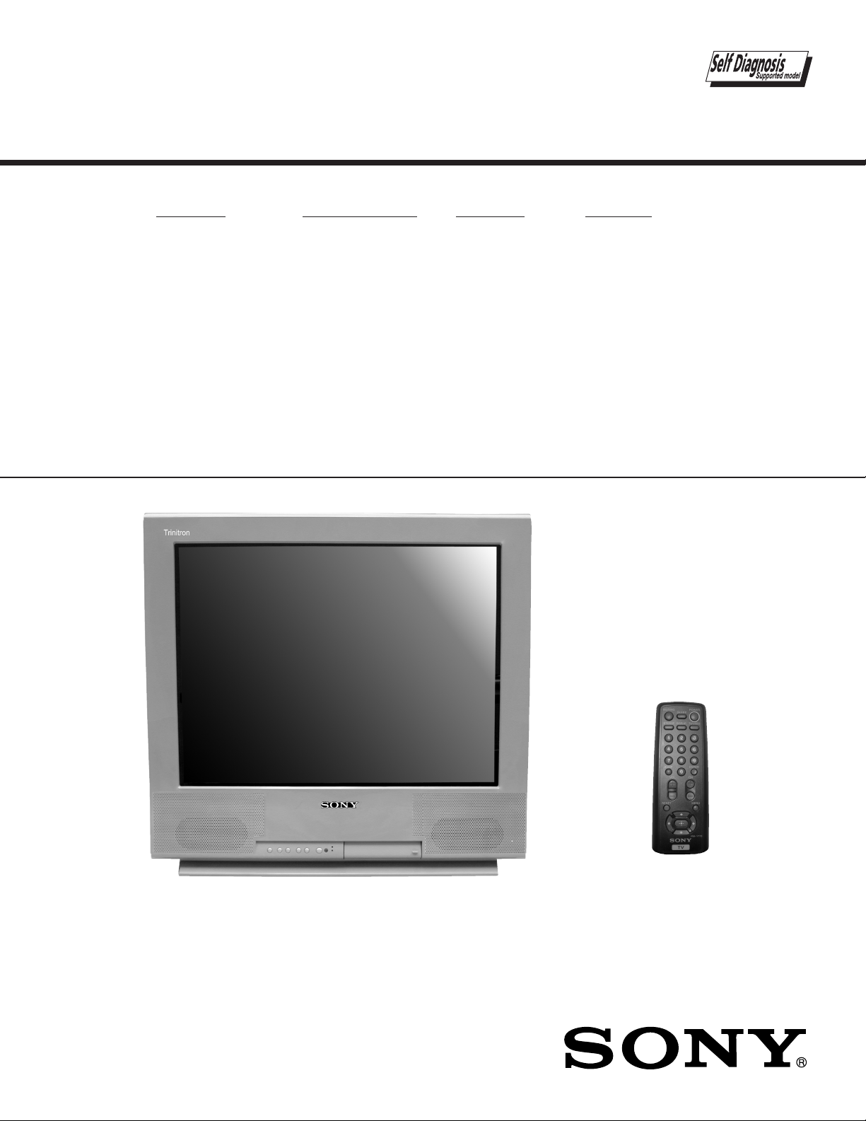
SONY KV25FS12, KV25FS12C Service Manual
SERVICE MANUAL
MODEL NAME REMOTE COMMANDER DESTINATION CHASSIS NO.
BA-5
CHASSIS
KV-25FS12
KV-25FS12C
RM-Y173 E SCC-S38UA
RM-Y173 E SCC-S38VA
9-965-902-01
KV-25FS12
RM-Y173
TRINITRON® COLOR TELEVISION

TABLE OF CONTENTS
SECTION TITLE PAG E
Specifi cations.......................................................................................................................................3
Warnings and Cautions........................................................................................................................4
Safety Check-out .................................................................................................................................5
Self-Diagnostic Function......................................................................................................................6
1. Disassembly
1-1. Rear Cover Removal.....................................................................................................................8
1-2. Chassis Assembly Removal..........................................................................................................8
1-3. Service Position ............................................................................................................................8
1-4. Picture Tube Removal...................................................................................................................9
Anode Cap Removal Procedure...................................................................................................9
2. Set-up Adjustments
2-1. Beam Landing...............................................................................................................................10
2-2. Convergence................................................................................................................................. 11
2-3. Focus ............................................................................................................................................12
2-4. Screen (G2) .................................................................................................................................. 12
2-5. Method of Setting the Service Adjustment Mode..........................................................................13
2-6. White Balance Adjustments .......................................................................................................... 13
3. Safety Related Adjustments
3-1.
3-2. B+ Voltage Confi rmation and Adjustment .....................................................................................14
4. Circuit Adjustments
4-1. Setting the Service Adjustment Mode...........................................................................................16
4-2. Memory Write Confi rmation Method .............................................................................................16
4-3. Remote Adjustment Buttons and Indicators .................................................................................16
Adjustment Items..........................................................................................................................17
4-4. MB Board Adjustments.................................................................................................................19
5. Diagrams
5-1. Circuit Boards Location.................................................................................................................21
5-2. Printed Wiring Boards and Schematic Diagrams..........................................................................21
5-3. Block Diagram............................................................................................................................... 22
A Board ........................................................................................................................................24
CB Board...................................................................................................................................... 28
K Board ........................................................................................................................................30
MB Board .....................................................................................................................................31
VB Board ......................................................................................................................................35
5-4. Semiconductors............................................................................................................................36
6. Exploded Views
6-1. Chassis.........................................................................................................................................37
7. Electrical Parts List ...................................................................................................................................... 38
X
R564 Confi rmation Method (HV Hold Down Confi rmation) and Readjustments..................... 14
KV-25FS12 / 25FS12C
— 2 —
SPECIFICATIONS
KV-25FS12 / 25FS12C
Television system
NTSC
KV-25FS12
Power requirements 120V, 60Hz 220V, 50/60Hz
Number of Inputs/Outputs
1)
Video
S Video
Audio
Audio Out
Headphone Out
2)
3)
4)
2
1
2
1
1
Speaker output (W) 7.5 x 2
Power Consumption (W)
In use (Max) 165W
In Standby 1W
Dimensions(W/H/D)
mm 614.8 x 564.1 x 499.7
13
x 22 13/64 x 19 49/
in 24
/
64
Mass
kg
lbs
1)
1 Vp-p 75 ohms unbalanced, sync negative
2)
Y: 1 Vp-p 75 ohms unbalanced, sync negative
C: 0.286 Vp-p (Burst signal), 75 ohms
3)
500 mVrms (100% modulation), Impedance: 47 kilohms
4)
More than 408 mVrms at the maximum volume setting (variable)
More than 408 mVrms (fi x); Impedance (output): 2 kilohms
36 kg
79 lbs 6 oz.
KV-25FS12C
64
Channel coverage
VHF: 2-13/ VHF: 14-69/ CATV: 1-125
Picture tube
Flat Trinitron® tube
Visible screen size
25-inch picture measured diagonally
Actual screen size
27-inch measured diagonally
Antenna
75 ohm external terminal for VHF/UHF
Supplied Accessories
Remote Commander RM-Y173
Size AA (R6) batteries (2)
Dipole Antenna
Optional Assessories
Connecting cables: VMC-810S/820S, VMC-720M,
YC-15V/30V, RK74A
U/V mixer EAC-66
Design and specifi cations are subject to change without notice.
— 3 —

KV-25FS12 / 25FS12C
WARNINGS AND CAUTIONS
CAUTION
Short circuit the anode of the picture tube and the anode cap to the metal chassis, CRT shield, or carbon painted on the CRT,
after removing the anode.
WARNING!!
An isolation transformer should be used during any service to avoid possible shock hazard, because of live chassis. The chassis of
this receiver is directly connected to the AC power line.
! SAFETY-RELATED COMPONENT WARNING!!
Components identifi ed by shading and ! mark on the schematic diagrams, exploded views, and in the parts list are critical for
safe operation. Replace these components with Sony parts whose part numbers appear as shown in this manual or in supplements
published by Sony. Circuit adjustments that are critical for safe operation are identifi ed in this manual. Follow these procedures
whenever critical components are replaced or improper operation is suspected.
ATTENTION!!
Apres avoir deconnecte le cap de l’anode, court-circuiter l’anode du tube cathodique et celui de l’anode du cap au chassis metallique
de l’appareil, ou la couche de carbone peinte sur le tube cathodique ou au blindage du tube cathodique.
Afi n d’eviter tout risque d’electrocution provenant d’un chássis sous tension, un transformateur d’isolement doit etre utilisé lors de tout
dépannage. Le chássis de ce récepteur est directement raccordé à l’alimentation du secteur.
! ATTENTION AUX COMPOSANTS RELATIFS A LA SECURITE!!
Les composants identifi es par une trame et par une marque ! sur les schemas de principe, les vues explosees et les listes de
pieces sont d’une importance critique pour la securite du fonctionnement. Ne les remplacer que par des composants sony dont
le numero de piece est indique dans le present manuel ou dans des supplements publies par sony. Les reglages de circuit dont
l’importance est critique pour la securite du fonctionnement sont identifi es dans le present manuel. Suivre ces procedures lors de
chaque remplacement de composants critiques, ou lorsqu’un mauvais fonctionnement suspecte.
— 4 —

SAFETY CHECK-OUT
KV-25FS12 / 25FS12C
After correcting the original service problem, perform the following
safety checks before releasing the set to the customer:
1. Check the area of your repair for unsoldered or poorly soldered
connections. Check the entire board surface for solder splashes and
bridges.
2. Check the interboard wiring to ensure that no wires are “pinched” or
touching high-wattage resistors.
3. Check that all control knobs, shields, covers, ground straps, and
mounting hardware have been replaced. Be absolutely certain that
you have replaced all the insulators.
4. Look for unauthorized replacement parts, particularly transistors,
that were installed during a previous repair. Point them out to the
customer and recommend their replacement.
5. Look for parts which, though functioning, show obvious signs of
deterioration. Point them out to the customer and recommend their
replacement.
6. Check the line cords for cracks and abrasion. Recommend the
replacement of any such line cord to the customer.
7. Check the B+ and HV to see if they are specifi ed values. Make sure
your instruments are accurate; be suspicious of your HV meter if sets
always have low HV.
8. Check the antenna terminals, metal trim, “metallized” knobs, screws,
and all other exposed metal parts for AC leakage. Check leakage
as described below.
Leakage Test
The AC leakage from any exposed metal part to earth ground and from
all exposed metal parts to any exposed metal part having a return to
chassis, must not exceed 0.5 mA (500 microamperes). Leakage current
can be measured by any one of three methods.
1. A commercial leakage tester, such as the Simpson 229 or
RCA WT-540A. Follow the manufacturers’ instructions to use these
instructions.
2. A battery-operated AC milliampmeter. The Data Precision 245 digital
multimeter is suitable for this job.
3. Measuring the voltage drop across a resistor by means of a VOM
or battery-operated AC voltmeter. The “limit” indication is 0.75 V,
so analog meters must have an accurate low voltage scale. The
Simpson’s 250 and Sanwa SH-63TRD are examples of passive VOMs
that are suitable. Nearly all battery-operated digital multimeters that
have a 2 VAC range are suitable (see Figure A).
How to Find a Good Earth Ground
A cold-water pipe is a guaranteed earth ground; the cover-plate retaining
screw on most AC outlet boxes is also at earth ground. If the retaining
screw is to be used as your earth ground, verify that it is at ground
by measuring the resistance between it and a cold-water pipe with an
ohmmeter. The reading should be zero ohms.
If a cold-water pipe is not accessible, connect a 60- to 100-watt troublelight (not a neon lamp) between the hot side of the receptacle and the
retaining screw. Try both slots, if necessary, to locate the hot side on the
line; the lamp should light at normal brilliance if the screw is at ground
To Exposed Metal
Parts on Set
Trouble Light
Ohmmeter
0.15 F
1.5 K Ω
AC Outlet Box
AC
Voltmeter
(0.75 V)
Earth Ground
Figure A. Using an AC voltmeter to check AC leakage. Figure B. Checking for earth ground.
— 5 —
Cold-water Pipe

KV-25FS12 / 25FS12C
SELF-DIAGNOSTIC FUNCTION
The units in this manual contain a self-diagnostic function. If an error occurs, the STANDBY/TIMER LED will automatically begin to fl ash. The number
of times the LED fl ashes translates to a probable source of the problem. A defi nition of the STANDBY/TIMER LED fl ash indicators is listed in the
instruction manual for the user’s knowledge and reference. If an error symptom cannot be reproduced, the Remote Commander can be used to review
the failure occurrence data stored in memory to reveal past problems and how often these problems occur.
Diagnostic Test Indicators
When an error occurs, the STANDBY/TIMER LED will fl ash a set number of times to indicate the possible cause of the problem. If there is more than
one error, the LED will identify the fi rst of the problem areas.
Results for all of the following diagnostic items are displayed on screen. If the screen displays a “0”, and error has occurred.
Diagnostic Item
Description
Power does not turn on
+B overcurrent (OCP)*
I-Prot
IK (AKB)
No. of times
STANDBY/ TIMER
lamp fl ashes
Does not light
2 times
4 times
5 times
Self-Diagnositc
Display/
Diagnostic Result
2:0 or 2:1
4:0 or 4:1
5:0 or 5:1
Probable Cause Location
• Power cord is not plugged in.
• Fuse is burned out (F601). (A Board)
• H.OUT (Q502) is shorted.(A Board)
• IC702 is shorted. (CB Board)
• +13V is not supplied. (A Board)
• IC502 is faulty. (A Board)
• Viedo OUT (IC502) is faulty. (A Board)
• IC1301 is faulty. (MB Board)
• Screen (G2) is improperly adjusted.**
Detected Symptoms
• Power does not come on.
• No power is supplied to the TV.
• AC Power supply is faulty.
• Power does not come on.
• Load on power line is shorted.
• Has entered standby state after horizontal raster.
• Vertical defl ection pulse is stopped.
• Power line is shorted or power supply is stopped.
• No raster is generated.
• CRT Cathode current detection reference pulse
output is small.
*If a +B overcurrent is detected, stoppage of the vertical defl ection is detected simultaneously. The symptom that is diagnosed fi rst by the
mircrocontroller is displayed on the screen.
**Refer to Screen (G2) Adjustments in Section 2-4 of this manual.
Display of Standby/Timer LED Flash Count
2 times
4 times
5 times
LED ON 0.3 sec.
LED OFF 0.3 sec.
LED OFF
3 sec.
Standby/Timer LED
Diagnostic Item Flash Count*
+B Overcurrent 2 times
V-STOP 4 times
IK (AKB) 5 times
*One fl ash count is not used for self-diagnostic.
Stopping the Standby/Timer LED Flash
Turn off the power switch on the TV main unit or unplug the power cord from the outlet to stop the STANDBY/TIMER LAMP from fl ashing.
— 6 —
KV-25FS12 / 25FS12C
Self-Diagnostic Screen Display
For errors with symptoms such as “power sometimes shuts off” or “screen sometimes goes out” that cannot be confi rmed, it is possible to bring up
past occurrences of failure on the screen for confi rmation.
To Bring Up Screen Test
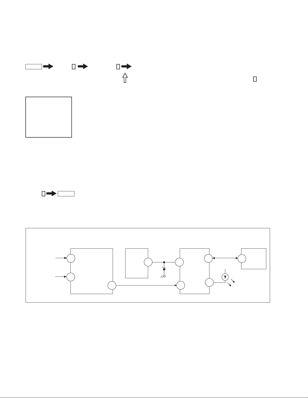
In standby mode, press buttons on the Remote Commander sequentially, in rapid succession, as shown below:
Display
Self-Diagnostic Screen Display
Handling of Self-Diagnostic Screen Display
Since the diagnostic results displayed on the screen are not automatically cleared, always check the self-diagnostic screen during repairs. When you
have completed the repairs, clear the result display to “0”.
Unless the result display is cleared to “0”, the self-diagnostic function will not be able to detect subsequent faults after completion of the repairs.
Clearing the Result Display
To clear the result display to “0”, press buttons on the Remote Commander sequentially when the diagnostic screen is displayed, as shown below:
Channel
Quitting the Self-Diagnostic Screen
To quit the entire self-diagnostic screen, turn off the power switch on the Remote Commander or the main unit.
Channel
SELF DIAGNOSTIC
2: 000
3: N/A
4: 000
5: 001
101: N/A
8
ENTER
5
Sound Volume - Power ON
Note that this differs from entering the Service Mode (Sound Volume
Numeral “0” means that no fault was detected.
Numeral “1” means a fault was detected one time only.
+
).
Self-Diagnostic Circuit
FROM
CB BOARD
IC702 PIN 5
MB BOARD
IC1301
Y/CHROMA JUNGLE
21
IK IN
A BOARD
IC502
V. OUT
REF
3
MB BOARD
IC1001
SYSTEM
IO-BDAT
17
I-Prot
36
MB BOARD
IC1003
MEMORY
5
BDA
A BOARD
18
FROM
IC501
PIN 3
+B overcurrent (OCP)
Occurs when an overcurrent on the +B (135V) line is detected by pin 18 of IC1301 (MB Board). If the voltage of pin 18 of IC1301 (MB Board) is less
than 1V when V.SYNC is more than seven verticals in a period, the unit will automatically turn off.
I-Prot
Occurs when an absence of the vertical defl ection pulse is detected by pin 17 of IC1001 (MB Board). Power supply will shut down when waveform
interval exceeds 2 seconds.
IK (AKB)
If the RGB levels* do not balance within 2 seconds after the power is turned on, this error will be detected by IC1301 (MB Board). TV will stay
on, but there will be no picture.
*(Refers to the RGB levels of the AKB detection Ref pulse that detects 1K).
HP/PROTECT
SDA
35
37
IO-SDAT
O-LED
18
DISPLAY
— 7 —
SECTION 2: SET-UP ADJUSTMENTS
KV-25FS12 / 25FS12C
The following adjustments should be made when a complete
realignment is required or a new picture tube is installed.
These adjustments should be performed with rated power supply
voltage unless otherwise noted.
Set the controls as follows unless otherwise noted:
VIDEO MODE: Standard
PICTURE CONTROL: Normal
BRIGHTNESS CONTROL: Normal
2-1. BEAM LANDING
Before beginning adjustment procedure:
1. Degauss the entire screen.
2. Feed in the white pattern signal.
ADJUSTMENT PROCEDURE
1. Input a raster signal with the pattern generator.
2. Loosen the defl ection yoke mounting screw, and set the purity control
to the center as shown below:
Purity Control
Perform the adjustments in order as follows:
1. Beam Landing
2. Convergence
3. Focus
4. Screen (G2)
5. White Balance
Note Test Equipment Required:
1. Color Bar Pattern Generator
2. Degausser
3. DC Power Supply
4. Digital Multimeter
6. Switch over the raster signal to red and blue and confi rm the
condition.
7. When the position of the defl ection yoke is determined, tighten it with
the defl ection yoke mounting screw.
8. If landing at the corner is not right, adjust by using the disk magnets.
3. Turn the raster signal of the pattern generator to green.
4. Move the defl ection yoke backward, and adjust with the purity control
so that green is in the center and red and blue are even on both
sides.
Blue Red
Green
5. Move the defl ection yoke forward, and adjust so that the entire screen
becomes green.
— 10 —
Disk magnets
or rotatable disk
magnets correct
these areas (a-d)
b
d
Purity control
corrects this area
ba
cd
Deflection yoke positioning
corrects these areas
a
c

KV-25FS12 / 25FS12C
2-2. CONVERGENGE
Before starting convergence adjustments:
1 Perform FOCUS, VLIN and VSIZE adjustments.
2. Set BRIGHTNESS control to minimum.
3. Feed in dot pattern.
VERTICAL STATIC CONVERGENCE
1. Adjust V. STAT magnet to converge red, green and blue dots in the
center of the screen (Vertical movement adjust V.STAT RV701 to
converge).
R G B
Center dot
RV701
V.STAT
R
G
B
HORIZONTAL STATIC CONVERGENCE
If the blue dot does not converge with the red and green dots, peform
the following:
1. Move BMC magnet (a) to correct insuffi cient H.Static convergence.
2. Rotate BMC magnet (b) to correct insuffi cient V.Static convergence.
3. After adjusting the BMC magnet, repeat Beam Landing Adjustment.
V. S TAT
BMC MAGNET
PURITY
V.STAT magnet
2. Tilt the V. STAT magnet and adjust static convergence to open or close
the V. STAT magnet.
When the V. STAT magnet is moved in the direction of arrow a and b,
red, green, and blue dots move as shown below:
1
a
b
2
a
3
b
a
B
b
G
R
b
a
a
R
G
b
a
RG B
b
BG R
B
B
b
B
G
R
b
G
R
b
BMC magnet
a
— 11 —
KV-25FS12 / 25FS12C
DYNAMIC CONVERGENCE ADJUSTMENT
Before performing this adjustment, perform Horizontal and Vertical Static
Convergence Adjustment.
1. Slightly loosen defl ection yoke screw.
2. Remove defl ection yoke spacers.
3. Move the defl ection yoke for best convergence as
shown below:
BGR
R
B
G
G
R
B
B
G
R
RGB
RGB
G
B
BGR RGB
R
G
B
R
RGB
BGR
4. Tighten the defl ection yoke screw.
5. Install the defl ection yoke spacers.
4. Adjust XCV core to balance X axis.
5. Adjust YCH VR to balance Y axis.
6. Adjust vertical red and blue convergence with V.TILT (TLV VR.)
Note: Perform adjustment 3-6 while tracking items 1 and 2.
SCREEN-CORNER CONVERGENCE
1. Affi x a permalloy assembly corresponding to the misconverged areas:
b
d
a
a-d: screen-corner
misconvergence
cd
c
ba
2-3. FOCUS
1. Adjust FOCUS control for best pictures.
TLH PLATE ADJUSTMENT
1. Input crosshatch pattern.
2. Adjust PICTURE QUALITY to standard, PICTURE and BRIGHTNESS
to 50%, and OTHER to standard.
3 Adjust the Horizontal Convergence of red and blue dots by tilting the
TLH plate on the defl ection yoke.
RV701
V. S TAT
CB Board
VB
Board
TLH Plate
TLV
YCH
(TLV)
Focus (FV)
Screen (G2)
2-4. SCREEN (G2)
1. Input a dot pattern.
2. Set the PICTURE and BRIGHTNESS controls at minimum and
COLOR control at normal.
3. Adjust SBRT, GCUT, BCUT in service mode with an oscilloscope as
shown below so that voltages on the red, green, and blue cathodes
are 170 ± 2VDC.
B R R B
(R)(B) (B)(R)
TLH+
TLH-
XCV
— 12 —
170 ± 2.0 VDC
GND
pedestal
2-5. METHOD OF SETTING THE SERVICE
ADJUSTMENT MODE
SERVICE MODE PROCEDURE
1. Standby mode (power off).
2. Press
Display
Channel 5 Sound Volume + Power
on the Remote Commander (press each button within a second).
SERVICE ADJUSTMENT MODE ON
KV-25FS12 / 25FS12C
1. The CRT displays the time being adjusted.
Category
Mode
service
Signal
ntsc
Type
vchp
1
2. Press
3. Press
4. Press
or 4 on the Remote Commander to select the time.
3
or 6 on the Remote Commander to change the data.
ENTER
MUTING
then
Display
Display
Item
Item
defl
hsiz 16
00000000
00000000
to save into the memory.
SERVICE ADJUSTMENT MODE MEMORY
Turn the set off then on to exit Service Adjustment Mode.
Display
Category
Mode
service defl hsiz 16
Signal
ntsc
Type
vchp 00000000 00000000
Item
write
Item
Data
MUTING
ENTER
Green
Red
2-6. WHITE BALANCE ADJUSTMENTS
1. Input an entire white signal with burst.
2. Set to Service Adjustment Mode.
3. Set the PICTURE and BRIGHTNESS to minimum.
4. Adjust with SBRT if necessary.
5. Select GCUT and BCUT with
6. Adjust with
3
and 6 for the best white balance.
1
and 4 .
7. Set the PICTURE and BRIGHTNESS to maximum.
8. Select GDRV and BDRV with
9. Adjust with
3
and 6 for the best white balance.
10. To write into memory, press
1
and 4.
MUTING
then
ENTER
.
— 13 —

SECTION 3: SAFETY RELATED ADJUSTMENTS
KV-25FS12 / 25FS12C
3-1. X R564 CONFIRMATION METHOD
(HOLD-DOWN CONFIRMATION) AND
READJUSTMENTS
The following adjustments should always be performed when replacing
the following components which are marked with
diagram:
Part Replaced ( )
DY, T505, CRT, IC501 C507,
C520, C505, C509, C515, T504,
Y
on the schematic
Adjustment ( )
HV HOLD-DOWN
R564
T503, C551, L510, C546, C537,
C547, D517, D518, D519, R560,
R561, R562, R563, R565, R566,
R567, R525....................A Board
IC1301........................MB Board
PREPARATION BEFORE CONFIRMATION
1. Using a Variac, apply AC input voltage: 120-220 ±2 VAC.
2. Turn the POWER switch ON.
3. Input a white signal and set the PICTURE and BRIGHTNESS controls
to maximum.
4. Confi rm that the voltage between C546 (+) or TP503 and ground is
more than 97 VDC.
HOLD-DOWN OPERATION CONFIRMATION
1. Connect the current meter between Pin 11 of the FBT (T505) and
the PWB land where Pin 11 would normally attach (See Figure 1 on
the next page).
2. Input a dot signal and set PICTURE and BRIGHTNESS to minimum:
IABL = 100 ± 100µA.
3. Confi rm the voltage of A Board TP-600 is 135 ± 1 VDC.
4. Connect the digital voltmeter and the DC power supply via Diode
1SS119 to C546 (+) and ground (See Figure 1 on next page).
5. Increase the DC power voltage gradually until the picture blanks out.
6. Turn DC power source off immediately.
7. Read the digital voltmeter indication (standard < 138 ± 0.3 VDC).
8. Input a white signal and set PICTURE and BRIGHTNESS to
maximum: IABL = 1650 ± 100µA.
9. Repeat steps 4 to 7.
HOLD-DOWN READJUSTMENT
If the setting indicated in Step 2 of Hold-Down Operation Confi rmation
cannot be met, readjustment should be performed by altering the
resistance value of R564 component marked with
X
.
T505
FBT
ammeter
3.0 mA DC
range
ABL
+
-
A
IABL
3-2. B+ VOLTAGE CONFIRMATION AND
ADJUSTMENT
Note: The following adjustments should always be performed when
replacing the following components, which are marked with
schematic diagram on the A Board:
A BOARD: IC601, PH601
1. Using a Variac, apply AC input voltage: 130 ± 2 VAC
2. Input a dot signal.
3. Set the PICTURE and the BRIGHTNESS controls to minimum.
4. Confi rm the voltage of A Board TP-600 is <136 VDC.
5. If step 4 is not satisfi ed, replace the components listed above, then
repeat Steps 1 – 3.
Y
on the
— 14 —
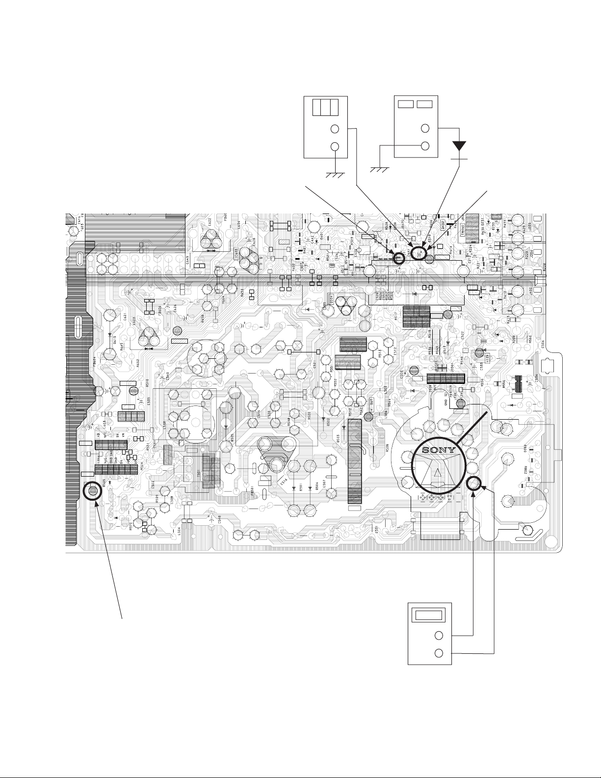
KV-25FS12 / 25FS12C
11119
+
+
+
+
18
1818
6
5
9
C
6
5
9
C
6
5
9
C
6
5
9
C
R601
R601
R601R601
R615
R615
R615R615
D616
D616
D616D616
B
6
1
F
0
B
6
1
F
0
B
6
1
F
0
B
6
1
F
0
C624
C624
C624C624
H.DRIVE
H.DRIVE
H.DRIVEH.DRIVE
CN511
C611
C611
C611C611
C654
C654
C654C654
CN506
CN506
CN506CN506
1111
1111
CN515
CN515
CN515CN515
+B
+B
+B+B
R515
R515
R515R515
CN511
CN511CN511
1111
R516
R516
R516R516
C536
C536
C536C536
D521
D521
D521D521
C554
C554
C554C554
4444
5555
7777
R503
R503
R503R503
C503
C503
C503C503
R502
R502
R502R502
R547
R547
R547R547
9
99
10
1018
1010
R
6
5
R
6
5
9
9
R
6
5
R
6
5
9
9
T503
T503
T503T503
L602
L602
L602L602
C629
C629
C629C629
H.PULSE
H.PULSE
H.PULSEH.PULSE
FB503
FB503
FB503FB503
R507
R507
R507R507
T502
T502
T502T502
Q501
Q501
Q501Q501
C504
C504
C504C504
4444
R518
R518
R518R518
C530
C530
C530C530
R529
R529
R529R529
5555
R531
R531
R531R531
6666
R539
R539
R539R539
C543
C543
C543C543
V DY -
V DY -
V DY -V DY -
V DY +
V DY +
V DY +V DY +
H DY -
H DY -
H DY -H DY H DY -
H DY -
H DY -H DY -
H DY +
H DY +
H DY +H DY +
H DY +
H DY +
H DY +H DY +
R545
R545
R545R545
POWER
SUPPLY
R438
R438
R438R438
R563
R563
R563R563
C546
C546
C546C546
R573
R573
R573R573
C541
C541
C541C541
D510
D510
D510D510
6
6
6
6
6
6
6
6
7
7
7
7
R540
R540
R540R540
C519
C519
C519C519
R537
R537
R537R537
TH501
TH501
TH501TH501
200V
200V
200V200V
D511
D511
D511D511
C552
C552
C552C552
L507
L507
L507L507
+
1SS119
C546
R225
R225
R403
R403
R403R403
H.PROT
H.PROT
H.PROTH.PROT
C542
C542
C542C542
2
2
2
2
4
4
4
4
2
2
2
2
C518
C518
C518C518
IC502
IC502
IC502IC502
1
1
1
1
R543
R543
R543R543
6
6
6
6
R225R225
D235
D235
D235D235
D234
D234
D234D234
C213
C213
C213C213
R218
R218
R218R218
R407
R407
R407R407
-13V
-13V
-13V-13V
HEATER
HEATER
HEATERHEATER
C211
C211
C211C211
Q205
Q205
Q205Q205
Q206
Q206
Q206Q206
C523
C523
C523C523
R532
R532
R532R532
1
1
1
1
CN502
CN502
CN502CN502
Q201
Q201
Q201Q201
D236
D236
D236D236
D232
D232
D232D232
R231
R231R232
R232
R231R231
R232R232
D233
D233
D233D233
R511
R511
R511R511
D518
D518
D518D518
R561
R561
R561R561
D514
D514
D514D514
C532
C532
C532C532
JR502
JR502
JR502JR502
T505 FBT
135V
135V
135V135V
T505
T505
T505T505
R226
R226
R226R226
R227
R227
R227R227
D520
D520
D520D520
D517
D517
D517D517
R558
R558
R558R558
R559
R559
R559R559
R557
R557
R557R557
Q505
Q505
Q505Q505
R554
R554
R554R554
D516
D516
D516D516
R555
R555
R555R555
R535
R535
R535R535
JUMPER-ID
JUMPER-ID
JUMPER-IDJUMPER-ID
R801
R801
R801R801
R803
R803
R803R803
R804
R804
R804R804
CN504
CN504
CN504CN504
DIGITAL
MULTIMETER
+
-
X
R564
R449
R449
R454
R454
R454R454
JR503
JR503
JR503JR503
R445
R445
R445R445
Q411
Q411
Q411Q411
D620
D620
D620D620
R506
R506
C510
C510
C510C510
T504
T504
T504T504
L509
L509
L509L509
C513
C513
C513C513
R505
R505
R505R505
C555
C555
C555C555
R504
R504
R504R504
R553
R553
R553R553
R506R506
C550
C550
C550C550
L502
L502
L502L502
L505
L505
L505L505
C517
C517
C517C517
E
E
E
E
C
C
C
C
0
2
Q
5
0
2
Q
5
0
2
Q
5
0
2
Q
5
O
H
-
O
H
-
U
T
U
T
O
H
-
O
H
-
U
T
U
T
C505
C505
C505C505
C509
C509
C509C509
C515
C515
C515C515
L510
L510
L510L510
D507
D507
D507D507
C524
C524
C524C524
D506
D506
D506D506
C511
C511
C511C511
L501
L501
L501L501
B
B
B
B
B
B
B
B
R568
R568
R568R568
R449R449
C448
C448
C448C448
R450
R450
R450R450
R567
R567
R567R567
R565
R565
R565R565
R525
R525
R525R525
Q503
Q503
Q503Q503
R447
R447
R447R447
R541
R541
R541R541
R514
R514
R514R514
FB502
FB502
FB502FB502
IC501
IC501
IC501IC501
R522
R522
R522R522
8888
R527
R527
1111
R527R527
B
B
B
E
B
E
E
E
E
E
E
E
C525
C525
C525C525
5555
4444
3333
2222
1111
C
N
5
0
1
C
N
5
0
1
C
N
5
0
1
C
N
5
0
1
R546
R546
R546R546
R533
R533
R533R533
R534
R534
C551
C551
R534R534
C551C551
TP600
AMMETER
3mA dc range
A
+
-
Figure 1
— 15 —

SECTION 4: CIRCUIT ADJUSTMENTS
ELECTRICAL ADJUSTMENTS BY REMOTE COMMANDER
Use the Remote Commander (RM-Y173) to perform the circuit adjustments in this section.
Test Equipment Required: 1. Pattern generator 2. Frequency counter 3. Digital multimeter 4. Audio oscillator
KV-25FS12 / 25FS12C
4-1. SETTING THE SERVICE ADJUSTMENT
MODE
1. Standby mode (Power off).
2. Press the following buttons on the remote commander within a
second of each other:
Display
Channel 5 Sound Volumne + Power
SERVICE ADJUSTMENT MODE ON
1. The CRT displays the item being adjusted.
Display
Item
Item
Data
2. Press
3. Press
4. Press
Category
Mode
service defl hsiz 16
Signal
ntsc
Type
vchp 00000000 00000000
1
or 4 on the Remote Commander to select the item.
3
or 6 on the Remote Commander to change the data.
MUTING
then
ENTER
to write into memory.
SERVICE ADJUSTMENT MODE MEMORY
Display
Category
Mode
service defl hsiz 16
Signal
ntsc
Type
vchp 00000000 00000000
8
ENTER
1. Press
Signal
Type
then
Category
Mode
service defl hsiz 16
ntsc
vchp 00000000 00000000
on the Remote Commander to initialize.
Display
Item
write
Item
Data
2. Turn set off then on to exit service adjustment mode.
Item
Item
Data
MUTING
write
ENTER
MUTING
ENTER
Carry out Step 1 when adjusting
IDs 0-6 and when replacing and
adjusting IC1003
Green
Red
Green
Red
4-2. MEMORY WRITE CONFIRMATION
METHOD
1. After adjustment, pull out the plug from the AC outlet, then replace
the plug in the AC outlet again.
2. Turn the power switch ON and set to Service Mode.
3. Call the adjusted items again to confi rm they were adjusted.
4-3. REMOTE ADJUSTMENT BUTTONS AND
INDICATORS
MUTING
(Enter into
memory
DISPLAY
(Service Mode)
1
Disp. (Item up)
2
(Device Item Up)
4
Disp. (Item down)
8
(Initialize)
VOLUME (+)
(Service Mode)
RM-Y173
POWER
(Service Mode)
3
Item (Data up)
6
Item (Data down)
5
(Device item down)
ENTER
(Enter into
memory
0
(Remove from
memory)
— 16 —
ADJUSTMENT ITEMS (1 OF 2)
KV-25FS12 / 25FS12C
FIX
Reg # ITEM FUNCTION RANGE
1 HSIZ Horizontal Size Adjustment 0-63 35
2 HPOS Horizontal Position Adjustment 0-63 33 21
3 VBOW Vertical Line Bowing Adj. 0-15 5 9
4 VANG Vertical line Bowing Slant Adj. 0-15 7 5
5 TRAP Horizontal Trapezoid Adj. 0-15 7 7
6 PAMP Horizontal PIN Distortion Adj. 0-63 7 32
7 UPIN Upper PIN Distortion Adj. 0-63 36 39
8 LPIN Lower PIN Distortion Adj. 0-63 36 39
9 VM Velocity Modulation On/Off 0,1 0
10 BLKO Vertical Blanking On/Off 0,1 0 0
11 VMLV Velocity Modulation Level 0-3 2
12 AGN2 Aging 2 0,1 0 0
13 REFP Reference Pulse Position 0,1 0 0
14 VBLK Vertical Blanking On/Off 0,1 0 0
15 JPSW 0,1 0 0
16 VSIZ Vertical Size Adjustment 0-63 40 49
17 VPOS Vertical Position Adj. 0-63 32 32
18 VLIN Vertical Linearity Adj. 0-15 7 6
19 SCOR Vertical "S" Correction Adjustment 0-15 6 8
20 VZOM 16:9 CRT Z Mode On/Off 0,1 0 0
21 EHT Vertical High-Voltage Correction 0-15 6 6
22 ASP Aspect Ratio Control 0-63 47 47
23 SCRL 16:9 CRT Z Mode Trans. Scroll 0-63 31 31
24 HBLK Horizontal Blanking On/Off 0,1 1 1
25 LBLK Left Blanking Adjustment 0-15 11 12
26 RBLK Right Blanking Adjustment 0-15 8 5
27 VUSN V Saw Waveform Compress 0,1 0 0
28 HDW Horizontal Drive Pulse Width 0,1 1 1
29 EWDC "Parabola" EW/ D.C. Adjustment 0.1 0 0
30 LVLN Lower Screen BTM Vertical Line Adj. 0-15 0 0
31 UVLN Upper Screen BTM Vertical Line Adj. 0-15 0 0
32 HTRP Horizontal Trapezoid Adj. 0,1 0 0
33 RDRV R Output Drive Control 0-63 31 36
34 GDRV G Output Drive Control 0-63 21 26
35 BDRV B Output Drive Control 0-63 21 25
36 RCUT R Output Cutoff Control 0-15 10 8
37 GCUT G Output Cutoff Control 0-15 6 6
38 BCUT B Output Cutoff Control 0-15 6 7
39 DCOL Dynamic Color On/Off 0,1 0 1
40 SHUE Sub HUE 0-31 15 15
41 SCOL Sub Color 0-31 15 15
42 SBRT Sub BRIGHTNESS 0-31 16 15
43 RON R Output On/Off 0,1 1 1
44 GON G Output On/Off 0,1 1 1
45 BON B Output On/Off 0,1 1 1
46 AXPL Axis PAL 0,1 0 0
47 AXNT Axis NTSC 0,1 1 0
48 CBPF Chroma BPF On/Off 0,1 1 1
49 CTRP Y TRAP FILTER On/Off 0,1 1 1
50 COFF Color On/Off 0,1 0 0
51 KOFF Set Color Killer 0,1 0 0
52 SSHP Sub SHARPNESS 0-15 5 7
DATA NTSC VIDEO RF
Palette mode controls this register
Palette mode controls this register
AVERAGE
DATA
38
— 17 —

ADJUSTMENT ITEMS (2 OF 2)
KV-25FS12 / 25FS12C
Reg # ITEM FUNCTION RANGE
53 SHPF SHARPNESS Circuit Fo 0,1
FIX
DATA NTSC VIDEO RF
Palette mode controls this register
AVERAGE
54 PREL Pre-Shoot / Over-Shoot 0,1 1 1
55 Y-DC DC Transmission Ratio Switching 0,1 1
56 GAMM Gamma Correction Amnt 0-3 1
Palette mode controls this register
Palette mode controls this register
57 ABLM ABL Mode Switching 0,1 1 1
58 VTH ABL CD VHT Switching 0,1 1 1
59 YDEL Y Delay Time Control 0-15 7 7
60 NCOL No Color ID 0,1 1 1
61 FSC FSC Out On/Off 0,1 1 1
62 K-ID Killer ID Control On/Off 0,1 0 0
63 HOSC Horizontal VCO Oscillation Freq. 0-15 7 7
64 VSS Vertical Sync Slice Level 0,1 0 0
65 HSS Horizontal Sync Slice Level 0,1 0 0
66 HMSK 0,1 0 0
67 VTMS Select Signal VTIM Pin 0-3 0 0
68 CDMD Vertical Count Down Mode Switching 0-3 3 0 0
69 AFC AFC Loop Gain Switching 0-3 0 0 0 0
70 FIFR Field Frequency 0-3 3 3 3
71 SBAL Sub Balance 0-15 5 7
72 SBAS Sub Bass 0-15 0 9
73 STRE Sub Treble 0-15 3 9
74 BBEL BBE Low 0-15 4 12
75 BBEH BBE High 0-15 5 9
76 SRND Surround 0,63 0 13
77 BBE BBE On/Off 0,1 0 1
78 DISP O.S.D Display Position 0-63 15 15
79 TROT Tilt Correction 0-63 31 31
80 HCLW Horizontal Count Lower Limit 0-127 16 16
81 HCHG Horizontal Count High Limit 0-127 64 64
82 ABL0 0,1 4 1
83 ABL1 0-7 Palette mode controls this register 7
84 SYSC Color System 0-7 0 6
85 VENH Vertical Enhancement 0-7 0 4
86 CBPC 0,1 3 0
87 BYCF 0,1 0 0
88 KILC 0,1 Palette mode controls this register 0
89 LDOT 0,1 1 0
90 CORE 0,1 1 0
91 CHTR 0,1 0
92 CHPF 0,1 1
93 ENHO 0,1 0
94 ID0 0,255 25 17
95 ID1 0,255 3 19
96 ID2 0,255 91 223
97 ID3 0,255 2 2
98 ID4 0,255 233 233
99 ID5 0,255 17 19
100 ID6 0,255 0 0
Notes:
No. 1-100 show the order that each adjustment mode may be selected while in Service Mode.
Data Range shows the range of possible setting for each Adjustment Mode.
Initial Data shows the standard settings for each Adjustment Mode.
Signal
Type
Chip
Version
Function
Mode
service id’s id5 19
ntsc
M37280MK-00SP VERB.O
DATA
1
ID
Number
00010011
Data
— 18 —

KV-25FS12 / 25FS12C
4-4. MB BOARD ADJUSTMENTS
H. FREQUENCY (FREE RUN) CHECK
1. Input a TV mode (RF) with no signal.
2. Connect a frequency counter to base of Q501
(TP-500 H. DRIVE) on the A Board.
3. Check H. Frequency for 15735 ± 200 Hz.
V. FREQUENCY (FREE RUN) CHECK
1. Select video 1 with no signal input.
2. Set the conditions for a standard setting.
3. Connect the frequency counter to TP-508 (V OUT) or CN501 pin
6
(V DY+) and ground on the A Board .
4. Check that V. Frequency shows 60 ± 4 Hz.
DRIVE (RDRV)
1. Input a color-bar signal and set the level to 75%.
2. Set in Standard mode.
3. Activate the Service Adjustment Mode.
3
4. Set both GON and BON items. Using
following values. Leave RON set to “1”.
Category
Mode
and
Display
Item
6
set each to the
Item
Data
DISPLAY POSITION ADJUSTMENT (DISP)
1. Input a color-bar signal.
2. Set to Service Adjustment Mode.
3. Select DISP with
4. Adjust values of DISP with
5. Write to memory by pressing
1
and 4 .
3
and 6 to adjust characters to the center.
MUTING
then
ENTER
.
6. Check to see if the text is displayed on the screen.
Item
Mode
Category
service micro disp 48
Signal
Type
ntsc
vchp
Display
Item
00000000 00000000
Data
SUB BRIGHT ADJUSTMENT (SBRT)
1. Input a monoscope signal.
2. Activate the Service Adjustment Mode.
3. Set the PICTURE and BRIGHTNESS to minimum.
4. Select the SBRT item with
5. Adjust the values of SBRT with
crosshatch.
6. Press
MUTING
then
1
and 4 .
ENTER
3
and 6 to obtain a faintly visible
to save into the memory.
service video rdrv 26
Signal
Type
ntsc
vchp
00000000 00000000
R ON: ON (1)
G ON: OFF (0)
B ON: OFF (0)
5. Connect an oscilloscope probe to CB Board, J701 Pin 12 (KR) (Red
Out) .
6. Select RDRV with
7. Adjust the value of RDRV with
1
and 4 .
3
and 6 for
92.0 ± 2 VDC.
92.0 ± 2VDC
8. Reset GON and BON values to “1”.
R ON: ON (1)
G ON: ON (1)
B ON: ON (1)
9. Press
MUTING
then
ENTER
to save into the memory.
SUB HUE, SUB COLOR ADJUSTMENT (SHUE,
SCOL)
1. Input a color-bar signal.
2. Activate the Service Adjustment Mode.
3. Connect an oscilloscope probe to CB Board, CN705 Pin
1
4. Select the SHUE and SCOL item with
and 4 .
5. While showing the SHUE item, adjust the waveform with
4
Blue Out.
1
and 4
until the second and third bars show the same level (V2 = V3 < 0.1
Vp-p).
6. While showing the SCOL item, adjust the waveform with
3
and 6
until the fi rst and fourth bars show the same level (V1 = V4 < 0.1
Vp-p).
7. Press
MUTING
then
V1
ENTER
V2 V3
V4
to save into the memory.
V. SIZE ADJUSTMENT (VSIZ)
1. Input a crosshatch signal.
2. Activate the Service Adjustment Mode.
3. Select the VSIZ item with
4. Adjust value of VPOS with
5. Press
MUTING
then
1
and 4 .
1
and 4 for the best vertical center.
ENTER
to save into the memory.
— 19 —
 Loading...