

Page 1
SERVICE MANUAL
FE-2
CHASSIS
MODEL
KV-24LS35B
KV-24LS35E
COMMA NDER DEST CHASSIS NO.
RM-932 FR SCC-Q54M-A
RM-932 ESP SCC-Q53N-A
MODEL
KV-24LS35U
COMMA NDER DEST CHASSIS NO.
RM-932 UK SCC-Q52J-A
Page 2

TABLE OF CONTENTS
Section Title Page Section Title Page
Specifications .................... 3
Connectors .................... 4
Self Diagnostic Software .................... 5
1. GENERAL
Switching On the TV and
Automatically Tuning .................... 6
Introducing the Menu System .................... 7
Menu Guide .................... 7
Teletext .................... 10
Specifications .................... 11
Troubleshooting .................... 11
2. DISASSEMBLY
2-1. Rear Cover Removal .................... 12
2-2. Chassis Removal .................... 12
2-3. A Board PWB Removal .................... 12
2-4. Service Position .................... 12
2-5. Picture Tube Removal .................... 13
3. SET-UP ADJUSTMENTS
3-1. Beam Landing .................... 14
3-2. Convergence .................... 15
3-3. Focus Adjustment .................... 17
3-4. Screen (G2), White Balance .................... 17
4. CIRCUIT ADJUSTMENTS
4-1. Electrical Adjustments .................... 18
4-2. Test Mode 1 .................... 20
4-3. Test Mode 2 .................... 20
5. DIAGRAMS
5-1. Block Diagrams (1) .................... 21
Block Diagrams (2) .................... 23
5-2. Circuit Board Location .................... 24
5-3. Schematic Diagrams and
Printed Wiring Boards .................... 24
* C Board .................... 25
* VM Board .................... 27
* F5 Board .................... 30
* H5 Board .................... 31
* D2 Board .................... 32
* D4 Board .................... 33
* A Board .................... 37
5-4. Semiconductors .................... 43
5-5. IC Blocks .................... 45
6. EXPLODED VIEWS
6-1. Chassis .................... 46
6-2. Picture Tube .................... 47
CAUTION
SHORT CIRCUIT THE ANODE OF THE PICTURE TUBE AND THE
ANODE CAP TO THE METAL CHASSIS, CRT SHIELD, OR THE
CARBON PAINTED ON THE CRT, AFTER REMOVAL OF THE
ANODE CAP.
WARNING !!
AN ISOLATION TRANSFORMER SHOULD BE USED DURING
ANY SERVICE WORK TO AVOID POSSIBLE SHOCK HAZARD
DUE TO LIVE CHASSIS, THE CHASSIS OF THIS RECEIVER IS
DIRECTLY CONNECTED TO THE POWER LINE.
SAFETY-RELATED COMPONENT WARNING !!
COMPONENTS IDENTIFIED BY SHADING AND MARKED
THE SCHEMATIC DIAGRAMS, EXPLODED VIEWS AND IN THE
PARTS LIST ARE CRITICAL FOR SAFE OPERATION. REPLACE
THESE COMPONENTS WITH SONY PARTS WHOSE PART
NUMBERS APPEAR AS SHOWN IN THIS MANUAL OR IN
SUPPLEMENTS PUBLISHED BY SONY.
£
ON
7. ELECTRICAL PARTS LIST .................... 48
ATTENTION
APRES AVOIR DECONNECTE LE CAP DE’LANODE,
COURT-CIRCUITER L’ANODE DU TUBE CATHODIQUE ET
CELUI DE L’ANODE DU CAP AU CHASSIS METALLIQUE DE
L’APPAREIL, OU AU COUCHE DE CARBONE PEINTE SUR LE
TUBE CATHODIQUE OU AU BLINDAGE DU TUBE
CATHODIQUE.
ATTENTION !!
AFIN D’EVITER TOUT RISQUE D’ELECTROCUTION
PROVENANT D’UN CHÁSSIS SOUS TENTION, UN
TRANSFORMATEUR D’ISOLEMENT DOIT ETRE UTILISÈ LORS
DE TOUT DÈPANNAGE LE CHÁSSIS DE CE RÈCEPTEUR EST
DIRECTMENT RACCORDÈ Á L’ALIMENTATION SECTEUR.
ATTENTION AUX COMPOSANTS RELATIFS Á
LA SECURITÈ!!
LES COMPOSANTS IDENTIFIÈS PAR UNE TRAME ET PAR UNE
MARQUE £ SUR LES SCHÈMAS DE PRINCIPE, LES VUES
EXPLOSÈES ET LES LISTES DE PIECES SONT D’UNE IMPOR-
TANCE CRITIQUE POUR LA SÈCURITÈ DU FONCTIONNEMENT,
NE LES REMPLACER QUE PAR DES COMPSANTS SONY DONT
LE NUMÈRO DE PIÈCE EST INDIQUÈ DANS LE PRÈSENT
MANUEL OU DANS DES SUPPLÈMENTS PUBLIÈS PAR SONY.
2
Page 3
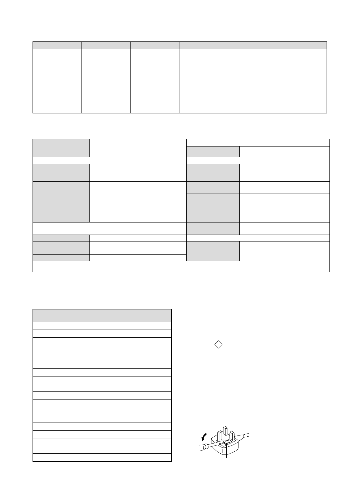
LEDOMMETI metsySnoisiveleT metsySoeretS egarevoClennahC metsySroloC
BL,I,K/D,H/G/B
EK/D,H/G/B
UI oeretSMACIN96E-12E:FHUI
MACIN/NAMREG
oeretS
MACIN/NAMREG
oeretS
21E-2E:FHV
01F-2F,21E-2E:FHV
96B-12B,96F-12F,96E-12E:FHU
Q-B,02S-1S,30S-10S:VTELBAC
14S-12S:REPYH
96E-12E:FHU
02S-1S,30S-10S:VTELBAC
14S-12S:REPYH
MACES,LAP
85.3CSTN,34.4CSTN
)NIOEDIV(
MACES,LAP
85.3CSTN,34.4CSTN
)NIOEDIV(
MACES,LAP
85.3CSTN,34.4CSTN
)NIOEDIV(
ebuTerutciP
rotcennocoruEnip-12:1
)dradnatsCELENEC(
rotcennocoruEnip-12:2
skcaJonohPoiduArofelbairavsrotcennoCtuptuO
kcajenohpdaeHkcajinimoerets
stupnioiduAskcajonohp
stupnioediVskcajonohp
tupnioediVSNIDnip4
nortinirTDFyalpsiDtalF
)sehcni42(mc16xorppA
)yllanogaidderusaemerutcipmc65xorppA(
]RAER[slanimreTtuptuO/tupnI snoitacificepSlareneG
.slangisoediVdnaoiduArofstupnI
.BGRrofstupnI
.slangisoiduAdnaoediVVTfostuptuO
.slangisoediVdnaoiduArofstupnI
.oediVSrofstupnI
.slangisoiduAdnaoediVVTfostuptuO
)elbatceles(
slangiS
]EDIS[slanimreTtuptuO/tupnI
tuptuodnuoS
rekaepstfeLdnathgiR)SMR(W7x2)rewoPcisuM(W41x2
stnemeriuqeRrewoPV042-022
noitpmusnoCrewoPW86
snoisnemiDmm194x144x396xorppA
thgieWgk5.82xorppA
seirosseccAdeilppuS
serutaeFrehtO
stnemeriuqerrewoP
)1(rednammoCetomeR239-MR
)2(yrettab6RdetangisedCEI
txeteleT,noitcetedotuAmetsysVT
ybloDlautriV
lortnoCderarfnI:metsySlortnoCetomeR
cdV3
noitangisedCEIseirettab2
)AAezis(6R
.ecitontuohtiwegnahcottcejbuserasnoitacificepsdnangiseD
metI
emaNledoM
bmoClaPFFOFFOFFO
PIPFFOFFOFFO
ytiroirPBGRNONONO
xoBrefooWFFOFFOFFO
1tracSNONONO
2tracSNONONO
)3(nitnorFNONONO
4tracSFFOFFOFFO
rotcejorPFFOFFOFFO
G/BmroNNONOFFO
ImroNNOFFONO
K/DmroNNONOFFO
SUAmroNFFOFFOFFO
LmroNNOFFOFFO
TASmroNFFOFFOFFO
MmroNFFOFFOFFO
txeteleTNONONO
oeretSmaciNNONONO
B53SL42-VK E53SL42-VK U53SL42-VK
WARNING (UK Models only)
The flexible mains lead is supplied connected to a B.S. 1363 fused
plug having a fuse of 5 AMP rating. Should the fuse need to be
replaced, use a 5 AMP FUSE approved by ASTA to BS 1362, ie one
ASA
that carries the
IF THE PLUG SUPPLIED WITH THIS APPLIANCE IS NOT SUITABLE FOR THE OUTLET SOCKETS IN YOUR HOME, IT SHOULD
BE CUT OFF AND AN APPROPRIATE PLUG FITTED. THE PLUG
SEVERED FROM THE MAINS LEAD MUST BE DESTROYED AS A
PLUG WITH BARED WIRES IS DANGEROUS IF ENGAGED IN A
LIVE SOCKET.
T
mark.
When an alternative type of plug is used, it should be fitted with a
5 AMP FUSE, otherwise the circuit should be protected by a 5 AMP
FUSE at the distribution board.
How to replace the fuse
Open the fuse compartment with
a screwdriver blade and replace
the fuse
FUSE
3
Page 4
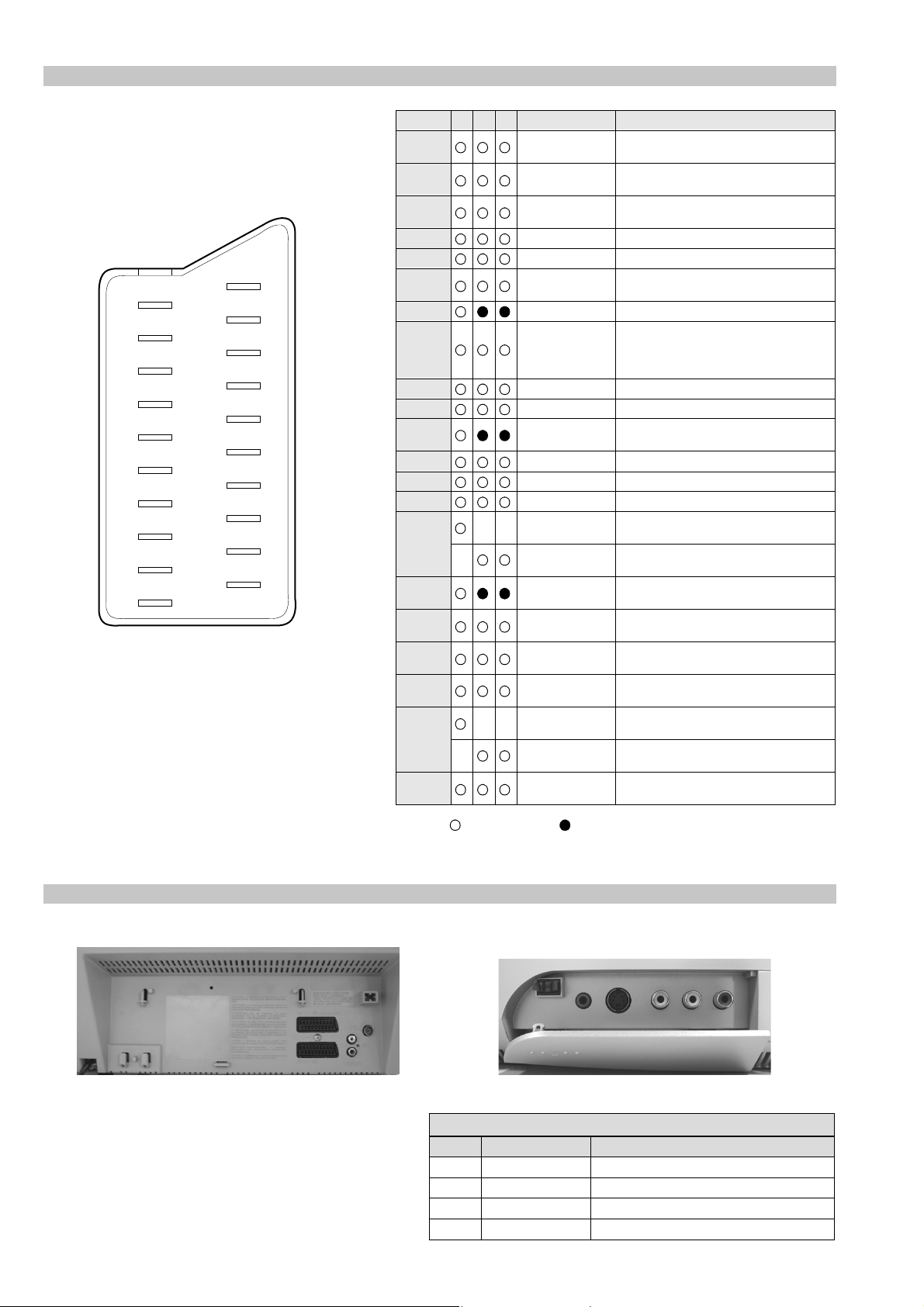
21 pin connector
21
19
17
15
13
11
9
7
5
3
1
20
18
16
14
12
10
8
6
4
2
Pin No 1 2 4 Signal Signal level
1 Audio output B
2
3
4 Ground (audio)
5 Ground (blue)
6 Audio input A
7 Blue input 0.7 +/- 3dB, 75 ohms positive
8 Function select
9 Ground (green)
10 Open
11 Green Green signal : 0.7 +/- 3dB, 75 ohms,
12 Open
13 Ground (red)
14 Ground (blanking)
15
_ (S signal Chroma
16 Blanking input
17 Ground (video
18 Ground (video
19 Video output 1V +/- 3dB, 75ohms, positive sync 0.3V
20
_ Video input
21 Common ground
(right)
Audio output B
(right)
Audio output A
(left)
(left)
(AV control)
_ _ Red input 0.7 +/- 3dB, 75 ohms, positive
input)
(Ys signal)
output)
input)
_ _ Video input 1V +/- 3dB, 75ohms, positive sync 0.3V
Y (S signal)
(plug, shield)
Standard level : 0.5V rms
Output impedence : Less than 1kohm*
Standard level : 0.5V rms
Output impedence : More than 10kohm*
Standard level : 0.5V rms
Output impedence : Less than 1kohm*
Standard level : 0.5V rms
Output impedence : More than 10kohm*
High state (9.5-12V) : Part mode
Low state (0-2V) : TV mode
Input impedence : More than 10K ohms
Input capacitance : Less than 2nF
positive
0.3 +/- 3dB, 75 ohms, positive
High state (1-3V) Low state (0-0.4V)
Input impedence : 75 ohms
(-3+10dB)
(-3+10dB)
1V +/- 3dB, 75ohms, positive sync 0.3V
(-3+10dB)
Connected Not Connected (open) * at 20Hz - 20kHz
Rear Connection Panel Front Connection Panel
S-Video
socket
oNniP langiS leveLlangiS
1dnuorG2dnuorG3tupni)langisS(YBd01+3-V3.0.cnySevitisop,mho57Bd3-/+V1
4tupni)langisS(C.cnySevitisop,mho57Bd3-/+V3.0
noitarugifnocniptekcosoediVS
4
Page 5
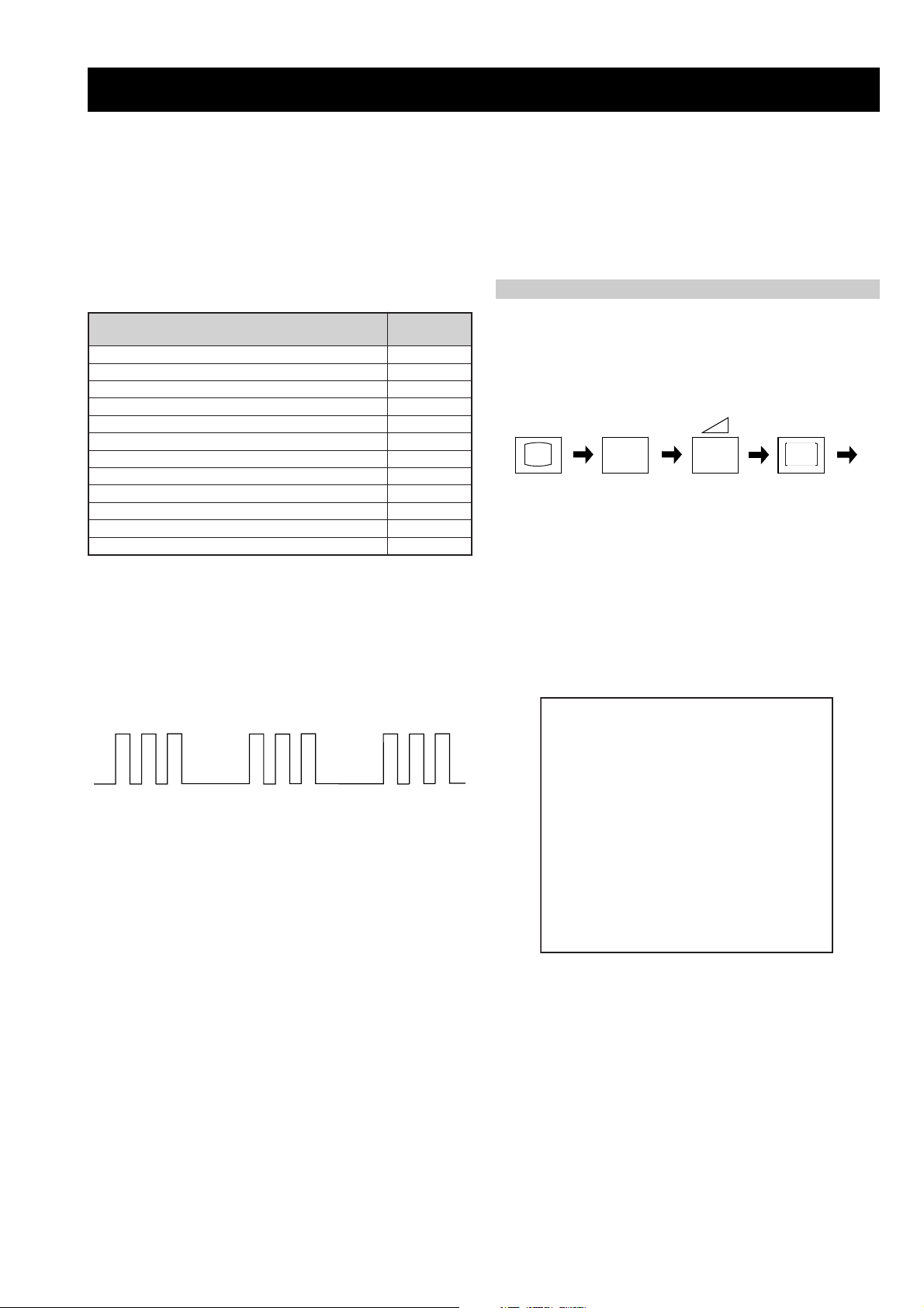
FE-2 SELF DIAGNOSTIC SOFTWARE
The identification of errors within the FE-2 chassis is triggered in one of two ways :- 1: Busy or 2: Device failure to respond to IIC. In the event
of one of these situations arising the software will first try to release the bus if busy (Failure to do so will report with a continuous flashing
LED) and then communicate with each device in turn to establish if a device is faulty. If a device is found to be faulty the relevant device number
will be displayed through the LED (Series of flashes which must be counted) See table 1., non fatal errors are reported using this method.
Each time the software detects an error it is stored within the NVM. See Table 2.
Table 1
egasseMrorrE
rorreoN00
devreseR10
)noitcetorPtnerruCrevO(PCO20
desUtoN30
cnySlacitreVoN40
norewoptarorrERKI50
norewoptawolsenilatadro/dnakcolcsubCII60
norewoptaegdelwonkcasubCIIonMVN70
desUtoN80
norewoptaegdelwonkcaonrenuT90
rorrErossecorPdnuoS01
rorrestlov8rellortnocelgnuJ11
Flash Timing Example : e.g. error number 3
StBy LED
ON ON ON
How to enter into Table 2
DEL
edoC
1. Turn on the main power switch of the TV set and enter into
the‘Stanby Mode’.
2. Press the following sequence of buttons on the Remote
Commander.
i+
(ON SCREEN (DIGIT 5) (VOLUME -) (TV)
DISPLAY)
5
-
3. The following table will be displayed indicating the error
count.
Table 2
UNEMRORRE
OFF
OFF
20E
30E
40E
50E
60E
70E
80E
90E
01E
11E
SRUOH
SETUNIM
PCO
A/NPVO
CNYSV
RKI
CII
MVN
ELGNUJ
RENUT
PDNUOS
V8
EMITGNIKROW
)552,0(
0
)552,0(
0
)552,0(
0
)552,0(
0
)552,0(
0
)552,0(
0
)552,0(
0
)552,0(
0
)552,0(
0
)552,0(
0
2
11
Note: To clear the error count data press ‘80’ on the Remote
commander.
5
Page 6
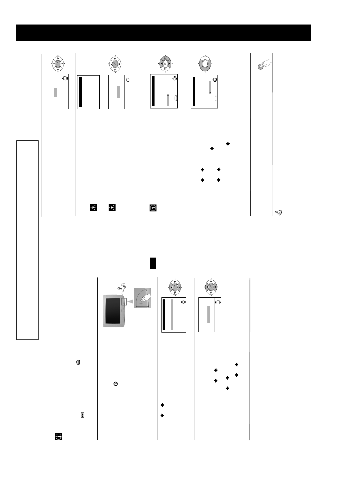
SECTION 1 GENERAL
OK
OK
No
Yes
automatic tuning?
Do you want to start
Auto Tuning
Programme 01
Channel C21
Searching...
This procedure could take some minutes. Please be
The Auto Tuning menu appears on the screen. Press the
4
OK button to select Yes.
The TV starts to automatically search and store all
available broadcast channels for you.
patient and do not press any buttons, otherwise the
5
OK
OK
Confirm
No channel found
Please connect aerial
If no channels were found during the auto tuning
process then a new menu appears automatically on
the screen asking you to connect the aerial. Please
connect the aerial (see page 6) and press OK. The
auto tuning process will start again.
automatic tuning will not be completed.
#
)
p
OK
OK
Programme Sorting
Programme:
and stored, the Programme Sorting menu appears
After all available broadcast channels are captured
6
MENU
01 TVE
02 TVE2
03 TV3
0 C33
05 C27
06 C58
Se ect channel:
Exit:
automatically on the screen enabling you to change
the order in which the broadcast channels appear on
the screen.
tuned order, go to step 7.
If you wish to keep the broadcast channels in the
a)
P
OK
·
3
0
OK
Programme Sorting
Programme:
01 TVE
02 TVE2
03 TV3
0 C33
05 C27
06 C58 05 C27
Select new position:
Exit: MENU
number with the broadcast channel you wish
If you wish to store the broadcast channels in a
1 Press the or button to select the programme
b)
different order:
programme number position for your selected
2 Press the or button to select the new
3 Repeat steps b)1 and b)2 if you wish to change
to rearrange, then press the button.
broadcast channel, then press .
MENU
the order of the other broadcast channels.
Press the MENU button to remove the menu from the
7
screen.
Your TV is now ready for use
The operating instructions mentioned here are partial abstracts from the ‘Operating
Instruction Manual’. The page numbers of the ‘Operating Instruction Manual’ remain
as in the manual.
GB
OK
OK
$
4Svenska
Norsk
Eng ish
Nederlands
Français
Italiano
Language
The first time you switch on your TV, a sequence of menu screens appear on the TV ena-
bling you to: 1) choose the language of the menu screen, 2) adjust the picture slant 3) search
and store all available broadcast channels and 4) change the order in which the broadcast
channels appear on the screen.
However, if you need to change any of these settings at a later date, you can do that by
selecting the appropriate option in the (Set Up menu) or by pressing the Auto Start Up
Button on the TV set.
Switching On the TV and Automatically Tuning
50Hz)
on. If the TV is off, press the on/off button on the TV
set to turn on the TV.
Connect the TV plug to the mains socket (220-240V AC,
The first time the TV set is connected, it is usually turned
1
displays automatically on the TV screen.
The first time you switch on the TV, a Language menu
Press the or button on the remote control to select
2
Select Language:
the language, then press the OK button to confirm your
selection. From now on all the menus will appear in the
selected language.
If picture slants, please
Because of the earth’s magnetism, the picture might slant.
3
OK
continued...
OK
Adjust now
Not necessary
adjust picture rotation
necessary and press OK.
then press OK and correct any slant of the picture
between –5 and +5 by pressing or . Finally press
OK to store.
If it is necessary, press or to select Adjust now,
If it is not necessary, press or to select Not
The Picture Rotation menu allows you to correct the
picture slants if it is necessary.
a)
b)
6
Page 7
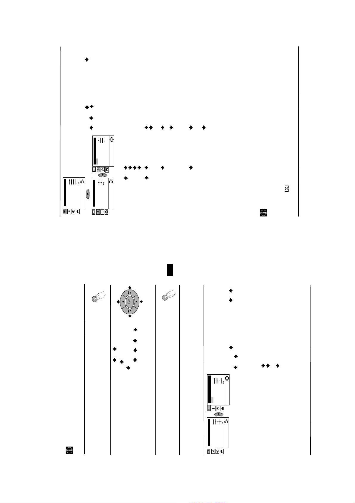
stay the same, independent of the
broadcast signal (e.g. in the case of
advertisements).
continued...
SOUND ADJUSTMENT
The “Sound Adjustment” menu allows you to
alter the sound adjustments.
To do this: after selecting the item you want to
alter, press . then press repeatedly /
K
Picture Adjustment
Mode: Personal
Contrast
Br ghtness
Co our
Sharpness
Hue
Reset
Level 1 Level 2 Level 3 / Function
/ or to adjust it and finally press OK
to store the new adjustment.
OK
Sound Adjustment
Mode: Personal
Treble
Bass
Balance
Sound Adjustment
Mode: Personal
Trebe
Bass
Balance
Reset
Reset
Dual Sound: Mono
De ail Adjustment
OK
Dual Sound: Mono
Detail Adjustment
Rock
This menu also contains two submenus as following:
Mode Personal (for individual settings)
On: Simulates the sound effect of Dolby
Virtual: Off: Normal.
*
Pop
Jazz
Detail Adjustment Dolby
On: Volume level of the channels will
Auto volume: Off: Volume level changes according
Pro Logic surround.
to the broadcast signal.
GB
On: Sound from the TV set.
TV Speakers: Off: Sound from external amplifier
switched to “Off”.
2 or Mono for mono channel if available. For a stereo broadcast you can choose Stereo or Mono.
• If you are listening to the TV through headphones, “Dolby Virtual” option will automatically be
• Select Reset and press OK to reset the sound to the factory preset levels.
connected to the audio outputs on
the rear of the TV set.
• In case of a bilingual broadcast select Dual Sound and set A for sound channel 1, B for sound channel
• Treble and Bass can only be altered if “Personal” mode is selected.
of four speakers with two speakers, when the broadcast audio signal is Dolby Surround encoded.
The sound effect can also be improved by connecting a suitable external amplifier (for details refer
to “Connecting to external audio Equipment” on page 19).
symbol are trademarks of Dolby Laboratories.
This TV has been designed to create the “Dolby Surround” sound effect by simulating the sound
*
“Off” and vice versa.
• If you switch “Dolby Virtual” to “On”, the “Auto volume” option will automatically be switched to
Manufactured under license from Dolby Laboratories. “Dolby”, “Pro Logic” and the double-D
*
MENU
OK
MENU
//or.
.
Your TV uses an on-screen menu system to guide you through the operations. Use the
following buttons on the Remote Control to operate the menu system:
Introducing and Using the Menu System
Press the MENU button to switch the first level menu on.
1
• To highlight the desired menu or option, press or.• To enter to the selected menu or option, press .
• To return to the last menu or option, press
• To alter settings of your selected option, press
2
• To confirm and store your selection, press OK.
Press the MENU button to remove the menu from the screen.
3
Level 1 Level 2 Level 3 / Function
Menu Guide
PICTURE ADJUSTMENT
or to adjust it and finally press OK to
The “Picture Adjustment” menu allows you to
alter the picture adjustments.
To do this: after selecting the item you want to
alter press , then press repeatedly / /
store the new adjustment.
This menu also allows you to customise the
K
P cture Adjustment
Mode: Personal
Contrast
Br ghtness
Colour
Sharpness
Hue
Reset
OK
Picture Adjustment
Mode: Personal
Contrast
Brightness
Co our
Sharpness
Hue
Reset
continued...
Personal (for individual settings).
Live (for live broadcast programmes, DVD
Movie (for films).
picture mode based on the programme you are
watching:
and Digital Set Top Box receivers).
• Brightness, Colour and Sharpness can only be altered if “Personal” mode is selected.
• Hue is only available for NTSC colour signal (e.g: USA video tapes).
• Select Reset and press OK to reset the picture to the factory preset levels.
7
Page 8
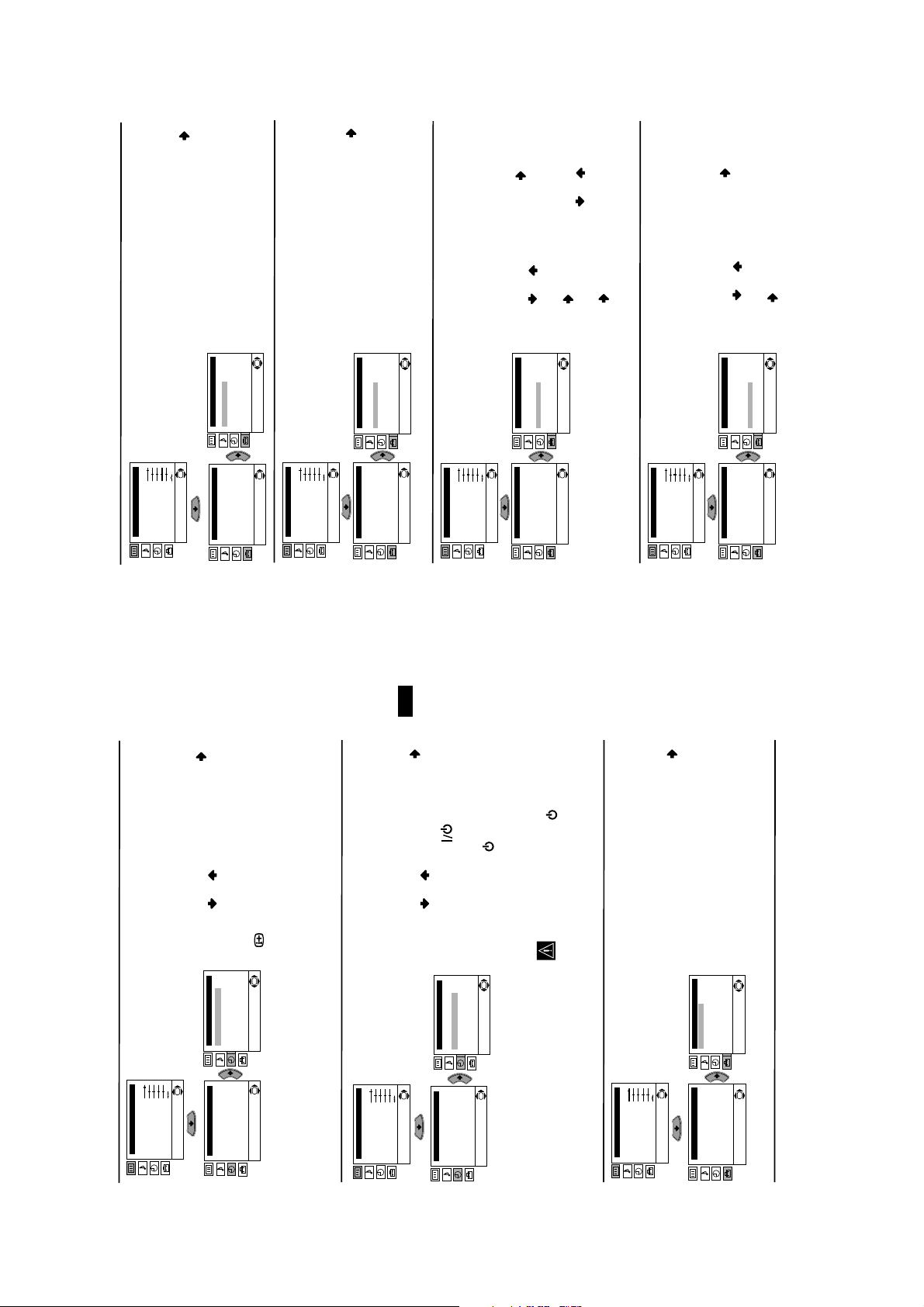
AUTO TUNING
The “Auto Tuning” option in the “Set Up”
menu allows you to automatically search for
and store all available TV broadcast channels.
To do this: after selecting the option, press
and then proceed in the same way as in TV
steps 4 and 5 of the section “Switching On the
TV and Automatically Tuning”.
PROGRAMME SORTING
The “Programme Sorting” option in the “Set
Up” menu allows you to change the order in
K
which the broadcast channels appear on the
screen.
To do this: after selecting the option, press
and then proceed in the same way as in step 6 b)
of the section “Switching On the TV and
Automatically Tuning”.
PROGRAMME LABELS
The “Programme Labels” option in the “Set
OK
Up” menu allows you to name a broadcast
channel using up to five characters (letters or
numbers).
To do this:
press or to select the programme
number with the broadcast channel you wish
to name.
column highlighted, press or to select
a letter or number (select “-“ for a blank), then
press to confirm this character. Select the
other four characters in the same way. Finally
1 After selecting the option, press , then
2 Press . With the first element of the Label
OK
press OK to store.
AV PRESET
The “AV Preset” option in the “Set Up” menu
allows you to designate a name to the external
equipment you have connected to the sockets of
this TV.
continued...
press or to select the input source you
wish to name (AV1 and AV2 are for the rear
Scarts and AV3 for front connectors). Then
To do this:
1 After selecting the option, press , then
press .
OK
K
P cture Adjustment
Mode: Personal
Contrast
Br ghtness
Colour
Sharpness
Hue
Reset
Level 1 Level 2 Level 3 / Function
Set Up
Set Up
Language
Auto Tunng
Programme Sortng
Progamme Labes
Language
Auto Tuning
Programme Sorting
Progamme Labels
AV Preset
Manua Programme Preset
Deta Set Up
OK
Set Up
Language
Auto Tuning
Programme Sorting
Progamme Labels
AV Preset
Manual Programme Preset
Detail Set Up
K
OK
Set Up
Language
Auto Tuning
Programme Sorting
Progamme Labels
AV Preset
Manual Programme Preset
Detail Set Up
K
K
Set Up
Language
Auto Tuning
Programme Sorting
Progamme Labels
AV Preset
Manual Programme Preset
Detail Set Up
K
K
Picture Adjustment
Mode: Personal
Contrast
Br ghtness
AV Preset
Manual Programme Preset
Detail Set Up
Colour
Sharpness
Hue
Reset
Set Up
Language
Auto Tuning
Programme Sorting
Progamme Labels
AV Preset
Manual Programme Preset
Detail Set Up
P cture Adjustment
Mode: Personal
Contrast
Brightness
Colour
Sharpness
Hue
Reset
Set Up
Language
Auto Tuning
Programme Sorting
Progamme Labels
AV Preset
Manual Programme Preset
Detail Set Up
P cture Adjustment
Mode: Personal
Contrast
Brightness
Colour
Sharpness
Hue
Reset
Set Up
Language
Auto Tuning
Programme Sorting
Progamme Labels
AV Preset
Manual Programme Preset
Detail Set Up
GB
continued...
on the remote
SLEEP TIMER
The “Sleep Timer” option in the “Timer” menu
allows you to select a time period for the TV to
switch itself automatically into the standby
mode.
To do this: after selecting the option press ,
then press or to set the time period delay
(max. of 4 hours) and finally press OK to store. • While watching the TV, you can press the
button on the remote control to display the
time remaining.
OK
Timer
Sleep Timer: Off
On Timer: Off
K
Timer
Sleep Timer: Of
On Timer: Off
Picture Adjustment
Mode: Personal
Contrast
Br ghtness
Co our
Sharpness
Hue
K
Reset
Level 1 Level 2 Level 3 / Function
control. After the selected length of time the TV
• One minute before the TV switches itself into
standby mode, the time remaining is displayed on
the TV screen automatically.
ON TIMER
The “On Timer” option in the “Timer” menu
allows you to select a time period for the TV to
switch itself automatically on from standby
mode.
To do this: after selecting the option press ,
OK
Picture Adjustment
Mode: Personal
Contrast
Brightness
Colour
Sharpness
Hue
Reset
switches on automatically.
then press or to set the time period delay
(max. 12 hours) and press OK to store. Finally
press the standby button
Timer
S eep Timer: Off
On Timer: Off
Timer
Sleep Timer: Off
On Timer: Off
8
If you have not activated the “On Timer”
option but the indicator on the TV set
flashes, please contact to your nearest
Sony Service Centre.
• The standby indicator on the TV set flashes
regularly to indicate that “On Timer” is active.
• Any loss of power will cause these settings to be
cleared.
K
LANGUAGE
The “Language” option in the “Set Up” menu
allows you to select the language that the
P cture Adjustment
Mode: Personal
Contrast
Br ghtness
Colour
Sharpness
menus are displayed in.
To do this: after selecting the option, press
and then proceed in the same way as in the step
2 of the section “Switching On the TV and Au-
tomatically Tuning”.
OK
Set Up
Language
Auto Tuning
Programme Sorting
Progamme Labes
AV Preset
Manual Programme Preset
Detail Set Up
Hue
K
Reset
Set Up
Language
Auto Tuning
Programme Sorting
Progamme Labes
AV Preset
Manual Programme Preset
OK
Detail Set Up
Page 9
to select a letter, number
r
continued...
Label a channel using up to five characters.
the programme number with the broadcast
channel you wish to name. When the TV
To do this: Highlighting the Programme
option, press the PROG +/- button to select
b)
K
Picture Adjustment
Mode: Personal
Contrast
Brightness
Colour
Sharpness
Hue
Reset
or “-“ for a blank. Press to confirm this
character. Select the other four characters in
the same way. After selecting all the
Next press o
Progamme Labes
AV Preset
Progamme Labes
AV Preset
Manua Programme Preset
Manual Programme Preset
K
Deta Set Up
K
Detail Set Up
characters, press OK twice to store.
broadcast you want to name appears on the
screen, select the Label option and press .
Set Up
Language
Auto Tunng
Programme Sortng
Set Up
Language
Auto Tuning
Programme Sorting
Level 1 Level 2 Level 3 / Function
Skip any unwanted programme numbers
or to adjust the fine tuning between -15
operating, however you can manually fine
tune the TV to obtain a better picture
Normally the automatic fine tuning (AFT) is
if the picture is distorted.
c)
To do this: while watching the channel (TV
and +15. Finally press OK twice to store.
Broadcast) you wish to fine tune, select the
AFT option and press . Next press
when they are selected with the PROG +/-
buttons.
d)
To do this: Highlighting the Programme
option, press the PROG +/- button to select
GB
and press . Next press or to select
the programme number you want to skip.
Yes. Finally press OK twice to confirm and
When the programme you want to skip
appears on the screen, select the Skip option
store.
To cancel this function afterwards, select “No”
instead of “Yes” in the step above.
labels (CABLE, GAME, CAM, DVD,
VIDEO or SAT), press or to select
the desired label and finally press OK to
store.
Edit and press . Then with the first
element highlighted, press or to
select a letter, number or “-“ for a blank,
then press to confirm this character.
Select the other four characters in the same
label:
a) If you want to use one of the 6 predefined
2 In the label column automatically appears a
b) If you want to set a different label, select
way and finally press OK to store.
Level 1 Level 2 Level 3 / Function
Preset broadcast channels or a video input
source one by one to the programme order of
Preset” option, press then with
Programme option highlighted press .
Press or to select on which
MANUAL PROGRAMME PRESET
The “Manual Programme Preset” option in the
“Set Up” menu allows you to:
a)
your choice. To do this:
1 After selecting the ”Manual Programme
Set Up
Language
K
Picture Adjustment
Mode: Personal
Contrast
Brightness
Colour
Sharpness
Hue
Reset
Set Up
Language
programme number you want to preset the
broadcast channel (for VCR, select
OK
Auto Tunng
Programme Sortng
Progamme Labes
AV Preset
Manua Programme Preset
Deta Set Up
OK
Auto Tuning
Programme Sorting
Progamme Labels
AV Preset
Manual Programme Preset
Detail Set Up
programme number “0”). Then press .
directly the channel number of the TV
Broadcast or the channel of the VCR signal. If
you do not know the channel number,
2 After selecting the Channel option, press .
Then press the number buttons to enter
press or to search for it. When you
channels.
Repeat all the above steps to tune and store more
tune the desired channel, press OK twice to
store.
continued...
9
Page 10
25
25
25
25
25
25
25
25
153
101
153
101
153
101
153
101
153
101
153
101
153
101
153
101
TELETEXT
TELETEXT
TELETEXT
TELETEXT
TELETEXT
TELETEXT
TELETEXT
TELETEXT
Index
Programme
News
Spo t
Index
Programme
News
Spo t
Index
Programme
News
Spo t
Index
Programme
News
Spo t
Index
Programme
News
Spo t
Index
Programme
News
Spo t
Index
Programme
News
Spo t
Index
Programme
News
Spo t
98
98
98
98
98
98
98
98
Weather
Weather
Weather
Weather
Weather
Weather
Weather
Weather
GB
Teletext is an information service transmitted by most TV stations. The index page of the
Teletext
Make sure to use a broadcast channel with a strong signal, otherwise teletext errors
teletext service (usually page 100) gives you information on how to use the service. To
operate teletext, use the remote control buttons as indicated below.
. You
:2/q
After selecting the TV channel which carries the teletext service you wish
to view, press .
Input 3 digits for the page number, using the numbered buttons.
• If you have made a mistake, retype the correct page number.
may occur.
To Switch On Teletext :
To Select a Teletext page:
• If the counter on the screen continues searching, it is because this page is not available. In that case,
Press PROG + ( ) or PROG - ().
Whilst you are viewing teletext, press . Press it again to cancel teletext mode.
input another page number
To access the next or preceding page:
To superimpose teletext on to the TV:
Some teletext pages have sub-pages which follow on automatically. To stop them, press
To freeze a teletext page:
/ . Press it again to cancel the freeze.
or
:1/
or to a VCR connected to this Scart,
If your VCR supports Smartlink, this
procedure is not necessary.
can record from this Scart any signal coming
from the TV or from external equipment
AV2 OUTPUT
The “AV2 Output” option in the “Detail Set Up”
menu allows you to select the source to be
connected to the Scart connector
output from the Scart connector
front connectors 3 and 3.
On
Au oTV0
0
To do this: after selecting the option, press .
Then press or to select the desired
OK
output signal: TV, AV1, AV3, YC3 or AUTO.
:2/q
RGB CENTRING
When connecting an RGB source, such as a
“PlayStation”, you may need to readjust the
horizontal position of the picture. In that case,
you can readjust it through the “RGB Centring”
option in the “Detail Set Up”.
Fastext service lets you access pages with one button push.
Press / . Press it again to conceal the information.
To reveal concealed information (e.g: answer to a quiz):
On
Press .
To Switch Off Teletext:
To do this: while watching an RGB source select
the “RGB Centring” option and press . Then
press or to adjust the centre of the
picture between –10 and +10. Finally press OK
to confirm and store.
K
AutoTV0
0
While you are in Teletext mode and Fastext is broadcast, a colour coded menu appears at
Fastext
the bottom of the teletext page. Press the colour button (red, green, yellow or blue) to access
the corresponding page.
PICTURE ROTATION
Because of the earth’s magnetism, the picture
might slant. In this case, you can correct the
picture slant by using the option “Picture
Rotation” in the “Detail Set Up” menu.
To do this: after selecting the option, press .
Then press or to correct any slant of the
picture between -5 and +5 and finally press OK
to store.
K
On
AutoTV0
0
K
Picture Adjustment
Mode: Personal
Contrast
Br ghtness
Colour
Sharpness
Hue
Reset
Level 1 Level 2 Level 3 / Function
Deta Set Up
Set Up
Auto Format
Nose Reduct on:
AV2 Oupu :
Language
Auto Tunng
RGB Centr ng:
Programme Sortng
Progamme Labes
Pcture Rotat on:
AV Preset
Deta Set Up
Auto Format
Nose Reduct on:
AV2 Oupu :
RGB Centr ng:
Pcture Rotat on:
K
K
K
Deta Set Up
Au o Format
Nose Reduct on:
AV2 Output:
RGB Centr ng:
Pcture Rotat on:
K
K
Picture Adjustment
Mode: Personal
Contrast
If you select “AUTO”, the output signal will always be the same one that is displayed on
Manua Programme Preset
Deta Set Up
If you have connected a decoder to the Scart
the screen.
please remember to change back the “AV2 Output” to “AUTO” or “TV” for correct
unscrambling.
Br ghtness
Colour
Sharpness
Hue
Reset
Set Up
Language
Auto Tunng
Programme Sortng
Progamme Labes
AV Preset
Manua Programme Preset
Deta Set Up
Picture Adjustment
Mode: Personal
Contrast
Br ghtness
Colour
Sharpness
Hue
Reset
Set Up
Language
Auto Tunng
Programme Sortng
Progamme Labes
AV Preset
Manua Programme Preset
Deta Set Up
10
Page 11
button
TV
Solution
•Check the aerial connection.
• Plug the TV in and press the button on the front of
the TV.
Adjustment” menu and select “Reset” to return to the
•If the standby indicator is on, press
on the remote control.
•Using the menu system, select the “Picture
Check that headphones are not connected.
Adjustment” menu and select “Reset” to return to
•
factory settings.
• Using the menu system, select the “Picture
• Turn off any equipment connected to the Scart
connector on the rear of the TV.
• Using the menu system, select the “Picture Rotation”
option in the “Detail Set Up” menu to correct the
picture slant.
factory settings.
•Check that the optional equipment is on and press the
button repeatedly on the remote control until the
Adjustment” menu.
correct input symbol is displayed on the screen.
• Press the +/- button on the remote control.
• Check that “TV Speakers” is “On” on the “Sound
Then enter to “Detail Set Up” option and set “AV2
Output” to “TV”.
Programme Preset” menu and adjust Fine Tuning
• Using the menu system, select the “Manual
(AFT) to obtain better picture reception.
• Using the menu system, select the “Noise Reduction”
option in the “Detail Set Up” menu and select
“Auto” to reduce the noise in the picture.
• Using the menu system, select the “Set Up” menu.
set according to the device you are using (VCR, TV or
• Check that the Media Selector on the remote control is
.
:2/q
DVD).
even when the Media Selector has been set correctly.
Enter the necessary code set as explained on “Remote
Control Configuration for VCR/DVD” chapter of this
instruction manual.
• If the remote control does not operate the VCR or DVD
• Replace the batteries.
• Contact your nearest Sony service centre.
Here are some simple solutions to the problems which may affect the picture and sound.
Troubleshooting
Problem
No picture (screen is dark) and no
sound.
Poor or no picture (screen is dark),
but good sound.
No picture or no menu information
from equipment connected to the
Scart connector.
Good picture, no sound.
No colour on colour programmes.
Distorted picture when changing
programmes or selecting teletext.
Picture slanted
GB
Sound Output:
2 x 14 W (music power)
2 x 7 W (RMS)
Power Consumption:
68 W
Standby Power Consumption:
0.54 W
Dimensions (w x h x d) :
Approx. 693 x 441 x 491 mm.
Weight:
28.5 Kg.
Accessories supplied:
1 Remote Control (RM-932)
2 Batteries (IEC designated)
Other features:
• Teletext, Fastext, TOPtext
• Sleep Timer
information on Smartlink, please refer to
• On Timer
• Smartlink (direct link between your TV set
and a compatible VCR. For more
the Instruction Manual of your VCR).
Noisy picture when viewing a TV
channel.
• Dolby Virtual
• Auto Format
No unscrambling or unstable picture
whilst viewing a scrambling channel
with a decoder connected through
the Scart connector
Remote control does not function.
If you continue to experience problems, have your TV serviced by qualified personnel.
The standby indicator on the TV
flashes even though the “On Timer”
function is not in use.
Never open the casing yourself.
Specifications
TV system: I Colour system:
PAL,
21-pin scart connector
input, RGB input, TV
audio/video output.
SECAM, NTSC 3.58, 4.43 (only Video In)
Channel Coverage:
I: UHF B21-B69
Picture Tube:
Flat Display FD Trinitron WIDE
24” (approx. 56 cm. measured
diagonally)
Rear Terminals
:1/
(CENELEC standard)
including audio/video
(CENELEC standard)
including audio / video
input, S video input,
selectable audio / video
output and Smartlink
interface.
21-pin Scart connector
:2/q
(SMARTLINK)
audio outputs (Left/
11
Right) - phono jacks
3 S Video input – 4 pin DIN
Front Terminals
q
…3 video input – phono jack
3 audio input – phono jacks
headphones jack
Design and specifications are subject to change without notice.
Ecological Paper- Totally Chlorine Free
Page 12
SECTION 2 DISASSEMBLY
2-1. Rear Cover Removal
=>
=>
=>
<=
=> <=
=>
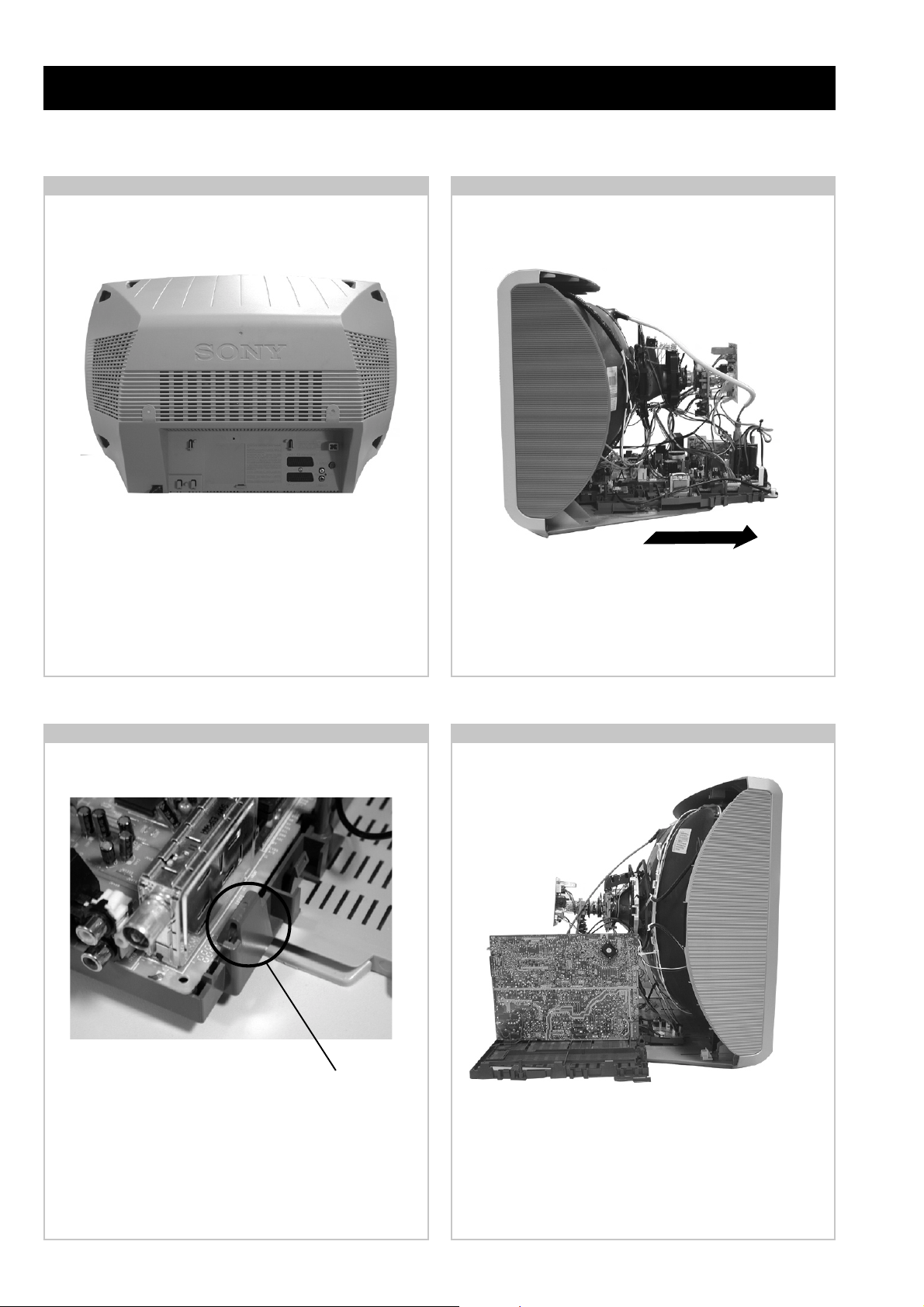
Release the mains power cable from its securing posts.
Remove the rear cover fixing screws indicated. Pull the rear
cover away from the front beznet.
2-2. Chassis Removal
T o remove lift the main bracket rear slightly and slide the
chassis away from the beznet. Ensure that the interconnecting
leads are released from their purse locks to prevent damage
being caused.
Clip.
Release the 5 securing clips located at the side and front of the
chassis and slide the PWB clear of the bracket.
2-4. Service Position2-3. A Board PWB Removal
Place the A Board PWB in the position indicated to carry out
servicing.
12
Page 13
2-5. Picture Tube Removal
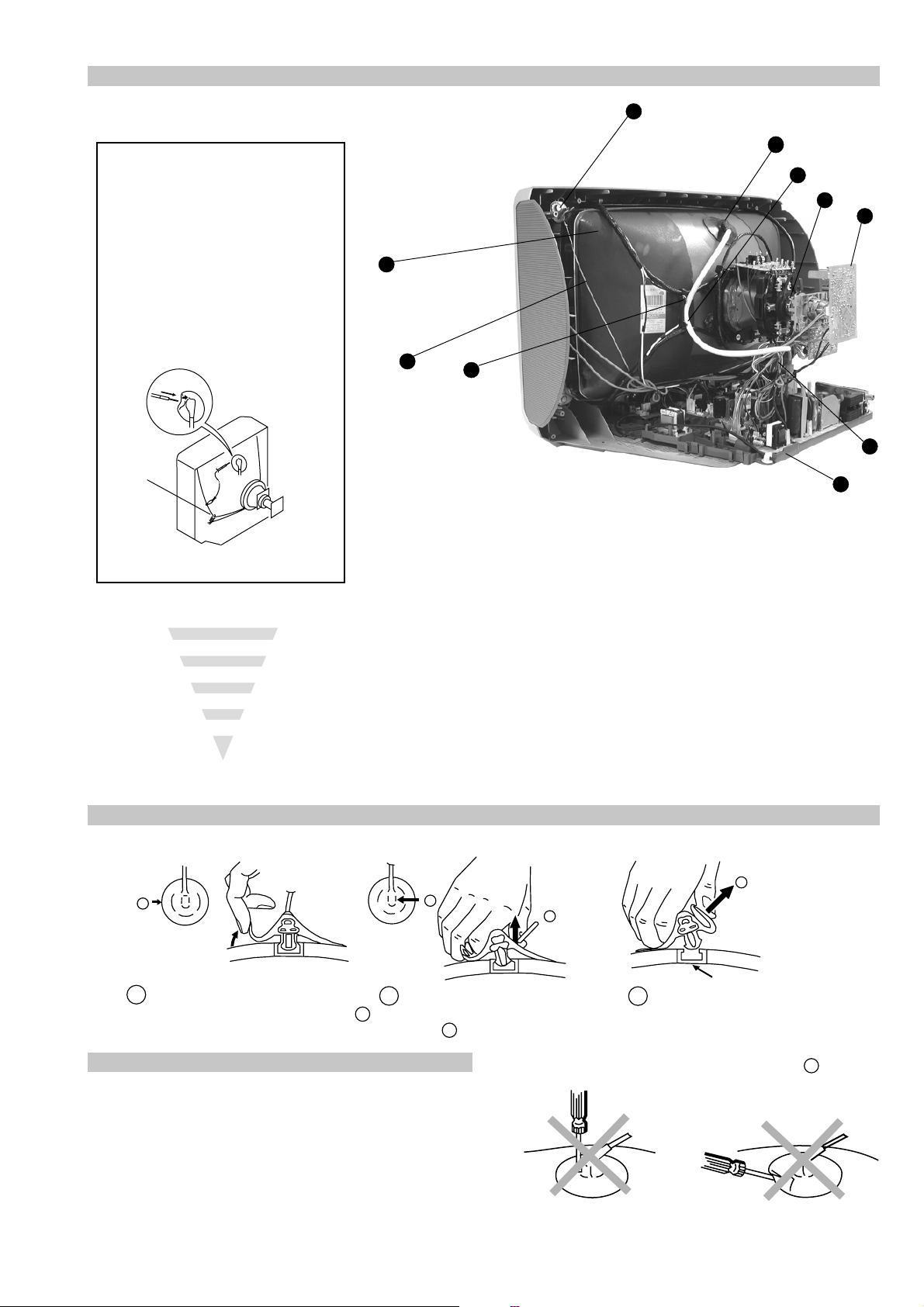
WARNING:
BEFORE REMOVING
THE ANODE CAP
High voltage remains in the CRT even
after the power is disconnected. To
avoid electric shock, discharge CRT
before attempting to remove the anode
cap. Short between anode and CRT
coated earth ground strap.
9
1
2
6
4
8
Coated Earth
Ground Strap
10
7
3
5
1. Discharge the anode of the CRT and remo ve the anode cap.
2. Release the EHT lead from its CRT support bracket.
3. Unplug all interconnecting leads from the Deflection yoke,
degaussing coils and CR T grounding strap.
4. Remove the C Board from the CRT.
5. Remove the chassis assembly .
6. Loosen the Deflection yoke fixing screw and remove.
7. Remove the Degaussing Coil holders.
8. Place the set with the CRT face do wn on a cushion.
9. Unscrew the four CRT f ixing scre ws [ located on each CRT
corner ] and remove the CR T.
10. Remove the Degaussing Coils.
Remove the CR T grounding strap and spring tentioners.
[T ake care not to handle the CR T by the neck.]
Removal of the Anode-Cap
* REMOVING PROCEDURES.
a
1
Turn up one side of the rubber cap in
the direction indicated by the arrow a
b
2 Using a thumb pull up the rubber cap
firmly in the direction indicated by the
arrow b
How to handle the Anode-Cap
1. To prevent damaging the surface of the anode-cap do not use
sharp materials.
2. Do not apply too great a pressure on the rubber, as this may cause
damage to the anode connector.
3. A metal fitting called a shatter hook terminal is fitted inside the
rubber cap.
4. Do not turn the rubber foot over excessively, this may cause
damage if the shatter hook sticks out.
c
b
Anode button
3 When one side of the rubber cap is
separated from the anode button, the
anode-cap can be removed by turning
up the rubber cap and pulling it up in
the direction of the arrow c
13
Page 14
SECTION 3 SET -UP ADJUSTMENTS
• When complete readjustment is necessary or a new picture
tube is installed, carry out the following adjustments.
• Unless there are specif ic instructions to the contrary , carry
out these adjustments with the rated power supply .
• Unless there are specif ic instructions to the contrary , set the
controls and switches to the following settings :
Contrast .................... 80% [or remote control ormal]
Brightness................... 50%
Preparation:
1. In order to reduce the influence of geomagnetism on the
set’s picture tube, face it in an easterly or westerly direction.
2. Switch on the set’s power and degauss with the degausser.
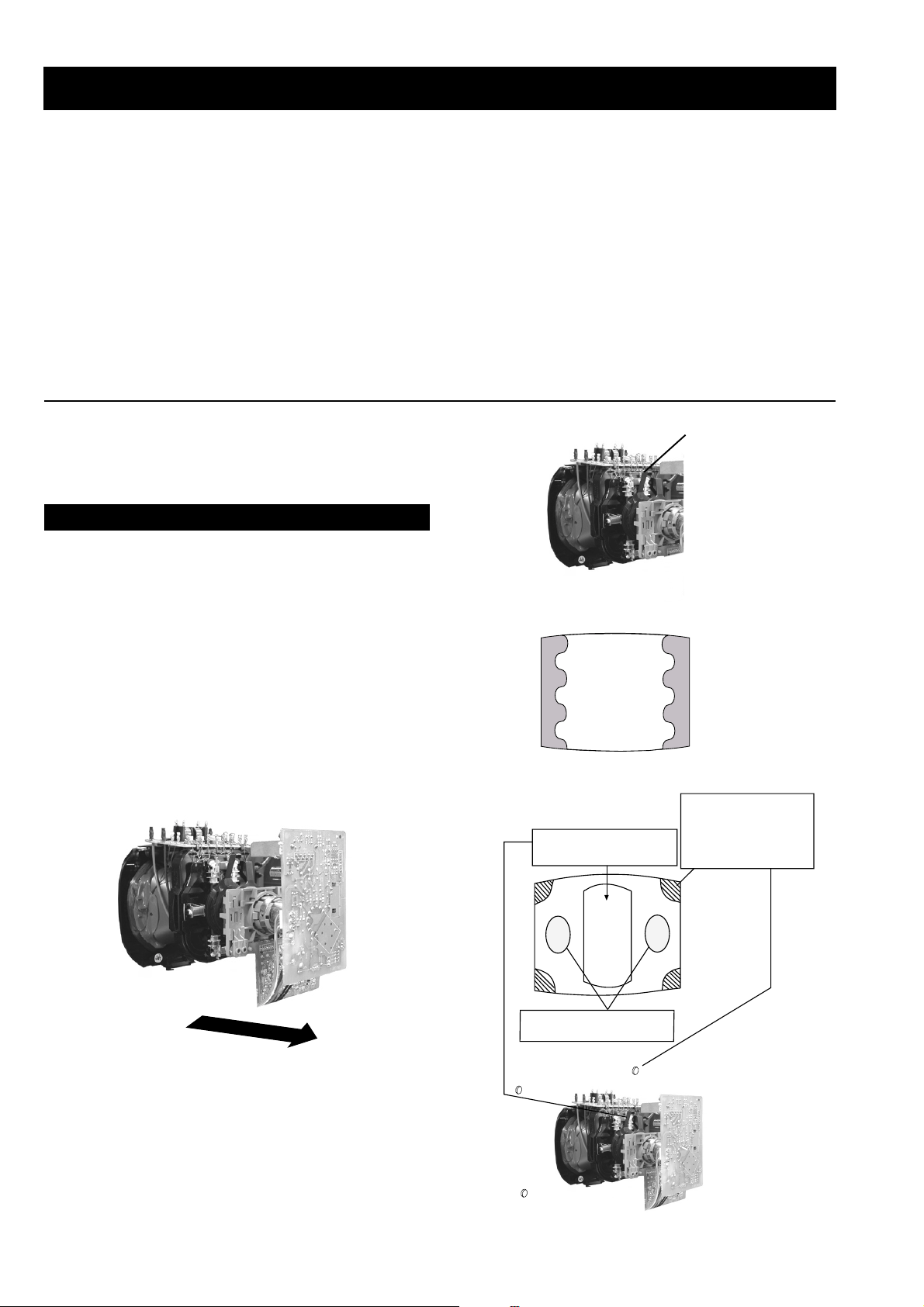
3-1. Beam Landing
1. Input an all white signal from the pattern generator. Set the
Contrast and Brightness to normal.
2. Set the pattern generator raster signal to Red.
3. Move the deflection yoke forward and adjust with the
purity control so that the Red is at the centre and the Blue
and Green take up equally sized areas on each side of the
screen. [See Fig.3-1 - 3-3].
4. Move the deflection yoke backwards and adjust so that the
entire screen becomes Red. [See Fig.3-1]
5. Switch the raster signal to Blue, then to Green and verify
the condition.
6. When the position of the deflection yoke has been
determined, fasten the deflection yoke with the screws.
7. If the beam does not land correctly in all the corners, use a
magnet to correct it. [See Fig.3-4]
Carry out the adjustments in the following order :
3-1. Beam Landing.
3-2. Convergence.
3-3. Focus.
3-4. White Balance.
Note : T est equipment required.
1. Color bar/pattern generator .
2. Degausser.
3. Oscilloscope.
4. Digital multimeter.
Fig. 3-2.
Fig. 3-3.
GREEN
RED
Purity control corrects
this area
Purity
BLUE
Disk magnets or
rotatable disk
magnets correct
these areas (a-d)
Fig. 3-1.
Caution :
High voltages are present on the Deflection yoke terminals
- take care when handling the Deflection yoke whilst carrying
out adjustments.
14
Disk Magnets
Fig.3-4
a
cd
Deflection yoke positioning
corrects these areas
b
Page 15
GBR
GBR
GBR
G
B
R
GBR
G
B
R
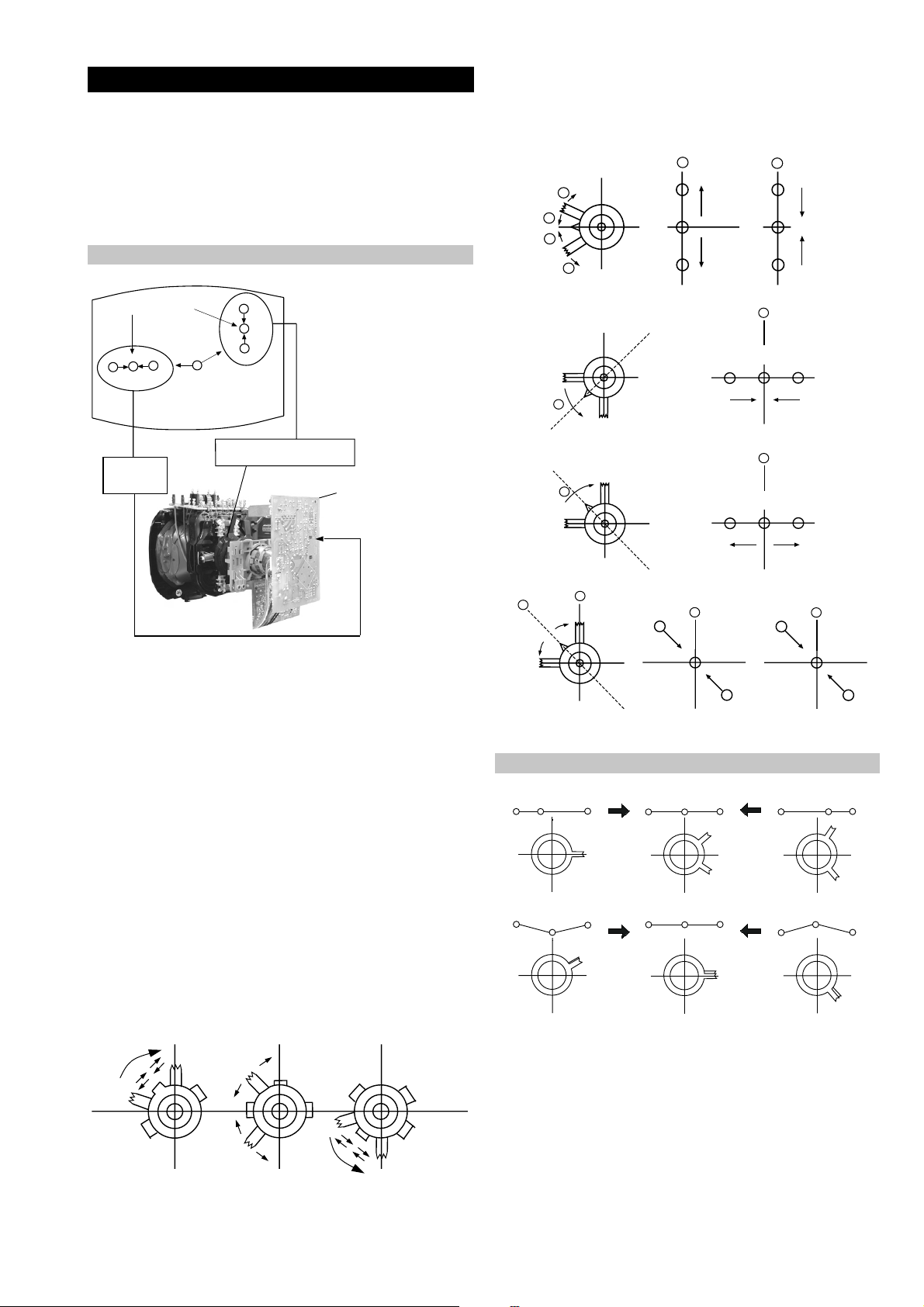
3-2. Con vergence
B
G
R
a
b
R
G
B
b
a
Preparation:
4. If the V.STAT magnet is moved in the direction of the (a)
and (b) arrows, the Red, Green and Blue points move as
indicated below .
• Before starting this adjustment, adjust the focus, horizontal
size and vertical size.
• Minimize the Brightness setting.
• Input a dot pattern from the pattern generator.
Horizontal and Vertical Static Convergence
Center dot
R
G
B
H STAT
convergence
control
R
G
B
V.STAT Vertical Static Magnet
C Board
RV702 (H STAT)
H STAT Convergence
(on mount side)
a
b
a
a
b
a
b
B
G
R
R
R
b
B
G
R
a
B
G
b
B
G
Fig.3-5
1. [Moving horizontally], adjust the H.ST AT control so that
the Red, Green and Blue points are on top of each other at
the centre of the screen.
Operation of the BMC (Hexapole) magnet.
2. [Moving vertically], adjust the V.STAT magnet so that the
Red, Green and Blue points are on top of each other at the
centre of the screen.
3. If the H.ST AT variable resistor is unable to bring the Red,
Green and Blue points together at the centre of the screen,
adjust the horizontal convergence with the H.STA T variable
resistor and the V.ST AT magnet in the manner indicated
below.
[In this case, the H.ST AT variable resistor and the V.STAT
magnet influence each other].
• Tilt the V.STAT magnet and adjust the static convergence by
opening or closing the V.ST AT magnet.
The movement of the magnets interact with each other and so
the respective dot position should be monitored while carrying
out this adjustment.
Use the H.STAT VR to adjust the Red, Green and Blue dots so
that they coincide at the centre of the screen
(by moving the dots in the horizontal direction).
15
Page 16
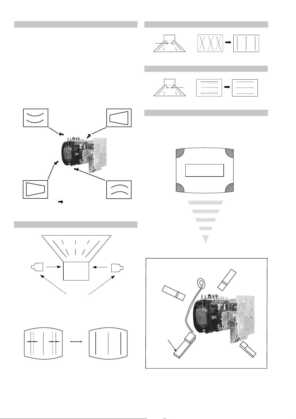
Geometry Adjustment.
Preparation:
Before starting this adjustment, adjust the horizontal and
vertical static convergence.
1. Remove the deflection yoke spacer .
2. Tilt the deflection yoke as indicated in the figure below and
optimise the geometry.
Tilting the D Y Up and Do wn will balance the upper and
lower pin adjustment.
Tilting the D Y Left and Right will balance the H-Trap
adjustment.
3. Re-install the deflection yoke spacer.
YCH Adjustment
YCH VR
Deflection Yoke
TL V Adjustment
Deflection Yoke
TLV VR
Screen Corner Convergence
If you are unable to adjust the corner conver gence properly ,
this can be corrected with the use of permalloy magnets.
HTIL Adjustment
Tilt Direction
Deflection Yoke
TLH pieces
a
a-d: screen-corner
convergence defect
c
Install the permalloy assembly
for the area that needs correcting.
b
b
d
a
HTIL correction can be performed by adding a TLH correction
assembly to the Deflection yoke.
Permalloy Assy
X-4387-214-1
16
d
Convergence adjustment with permalloy
c
Page 17
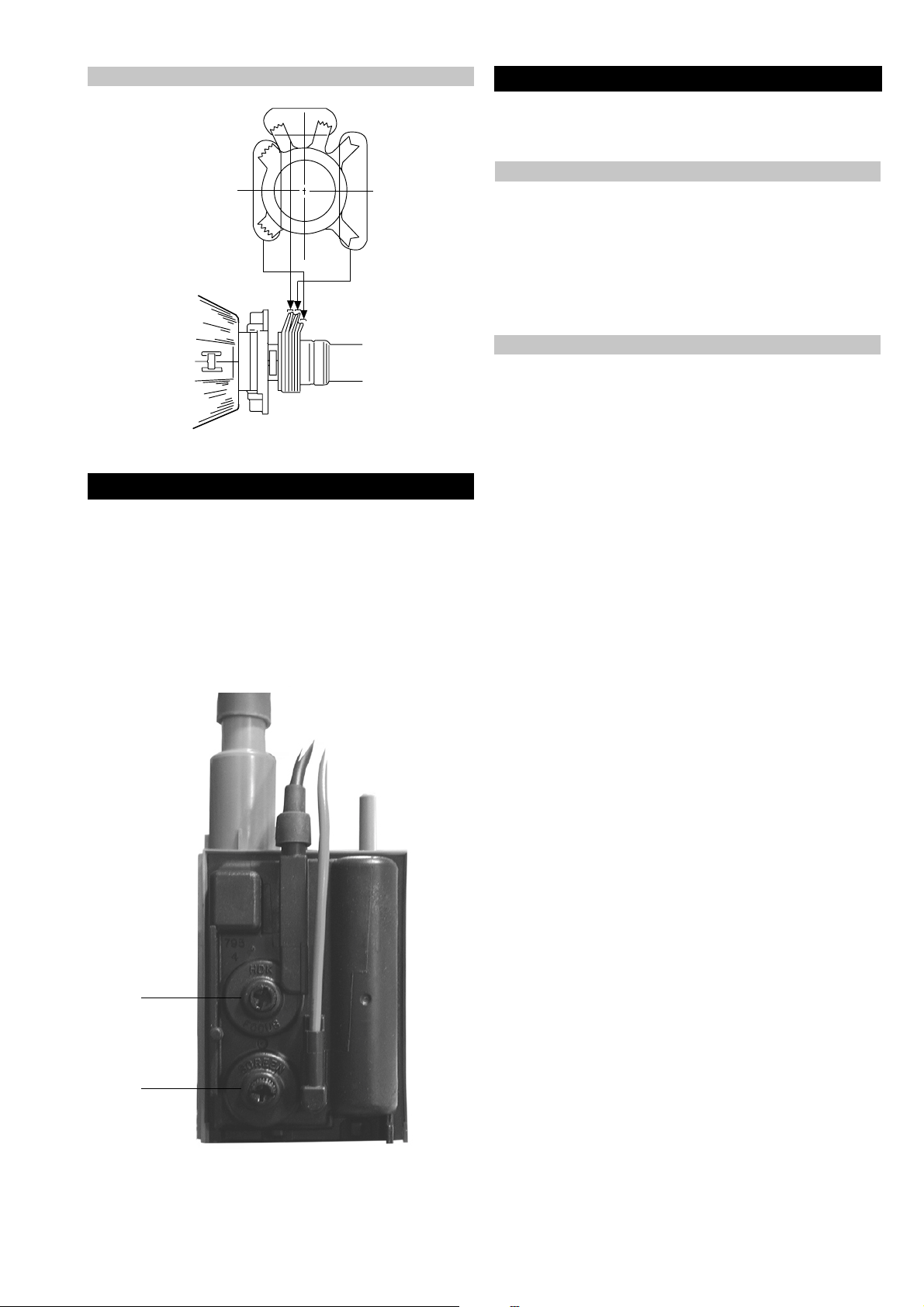
Layout of each control
V.STAT
Purity
BMC (Hexapole)
3-3. Focus Adjustment
1. Receive a television broadcast signal.
2. Normalize the picture setting.
3. Adjust the focus control located on the flyback transformer
to obtain the best focus at the centre of the screen.
Bring only the centre area of the screen into focus, the
magenta-ring appears on the screen. In this case, adjust the
focus to optimize the screen uniformly.
3-4. Screen (G2), White Balance
[Adjustment in the service mode using the remote
commander]
G2 adjustment
1. Input a dot signal from the pattern generator.
2. Set the Picture, Brightness and Colour to minimum.
3. Apply 175V DC from an external power supply to the R, G
and B cathodes of the CRT.
4. Whilst watching the picture, adjust the G2 control [SCREEN]
located on the Flyback Transformer to the point just before
the flyback return lines disappear.
White balance adjustment for TV mode
1. Input an all-white signal from the pattern generator.
2. Enter into the ‘Service Mode’ by pressing ‘TEST’, ‘TEST’
and ‘MENU’ on the Service Commander.
3. Select ‘Service’ from the on screen menu display and press
the right arrow button on the remote commander .
4. The ‘Service’ menu will appear on the screen.
[See Page 18]
5. Set the ‘Contrast’ to MAX.
6. Set the ‘R-Drive’ to 25.
7. Adjust the ‘G-Drive’ and the ‘B-Drive’ so that the white
balance becomes optimum.
8. Press the ‘OK’ button to write the data for each item.
9. Set the ‘Contrast’ to MIN.
10. Adjust the ‘G-Cutoff’, and the ‘R-Cutoff’ with the left and
right buttons on the remote commander so that the white
balance becomes optimum.
11. Press the ‘OK’ button to write the data for each item.
Focus
Screen
17
Page 18
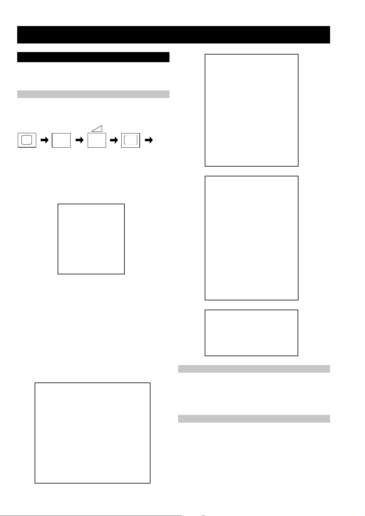
SECTION 4 CIRCUIT ADJUSTMENTS
4-1. Electrical Adjustments
Service adjustments to this model can be performed using the
suppliedemote Commander RM-932.
How to enter into the Service Mode
1. Turn on the main power switch and enter into the stand-by mode.
2. Press the following sequence of buttons on the Remote
Commander.
i+
(ON SCREEN (DIGIT 5) (VOLUME +) (TV)
DISPLAY)
5
‘TT—’ will appear in the upper right corner of the screen.
Other status information will also be displayed.
3. Press ‘MENU’ on the remote commander to obtain the following
menu on the screen.
ecivreS
ngiseD
sutatS
dnuoS
4. Move to the corresponding adjustment item using the
up or down arrow b uttons on the Remote Commander.
5. Press the right arrow button to enter into the required menu item.
6. Press the ‘Menu’ button on the Remote Commander to quit the
Service Mode when all adjustments have been completed.
+
yrtemoeG
tsujdaFI
uneMrorrE
03.1voeretS2-EF
hFFhFFatadyrotcaF
G1143PSM:eciveDPSM
ECIVRES
R-tesffO
G-tesffO
evirD-R
evirD-G
evirD-B
qerF-kaeP
yaleD-amuL
0CS
kaeP-etihW
tnocbuS
thgirbuS
locbuS
prahsbuS
.rBffotuC
DSOrB
TXTrB
YRTEMOEG
ytiraeniL-V
llorcS-V
klBH-tfeL
klBH-thgiR
elgnA-V
woB-V
ertneC-H
eziS-H
pmA-niP
niP-renroC-U
niP-renroC-L
esahPniP
epolS-V
eziS-V
noitcerroC-S
ertneC-V
mooZ-V
atnegaM
TSUJDAFI
)36,0(
)36,0(
)36,0(
)36,0(
)36,0(
)3,0(
)51,0(
)3,0(
)51,0(
)51,0(
)36,0(
)36,0(
)36,0(
)36,0(
)51,0(
)51,0(
)36,0(
)36,0(
)51,0(
)51,0(
)36,0(
)36,0(
)36,0(
)36,0(
)36,0(
)36,0(
)36,0(
)36,0(
)36,0(
)36,0(
)36,0(
)36,0(
)36,0(
)36,0(
jdA
jdA
52
jdA
jdA
0
8
2
51
4
13
jdA
13
06
01
9
jdA
23
8
6
jdA
jdA
jdA
jdA
jdA
jdA
jdA
jdA
53
jdA
jdA
jdA
32
04
Note :
• Before performing any adjustments ensure that the correct model
has been selected in the ‘Model Setting’ menu.
• After carrying out the service adjustments, to prevent the
customer
accessing the ‘Service Menu’ switch the TV set OFF and then
ON.
UNEMRORRE
20E
30E
40E
50E
60E
70E
80E
90E
01E
11E
SRUOH
SETUNIM
PCO
A/NPVO
CNYSV
RKI
CII
MVN
ELGNUJ
RENUT
PDNUOS
V8
EMITGNIKROW
)552,0(
0
)552,0(
0
)552,0(
0
)552,0(
0
)552,0(
0
)552,0(
0
)552,0(
0
)552,0(
0
)552,0(
0
)552,0(
0
2
11
tsujdACGA
etumotuA
niaGoiduA
gnitaGL
)51+,61-(0+
1
0
0
Sub Brightness Adjustment
1. Input a Monoscope pattern.
2. Press ‘TEST’ ‘TEST’ 13 on the Remote Commander.
3. Adjust the ‘Sub-Brightness’ data so that there is barely a
difference between the 0 IRE and 10 IRE signal levels.
Sub Contrast Adjustment
1. Input a video signal that contains a small 100% white area on a
black background.
2. Connect an digital voltmeter to Pin 10 of J701 [C Board].
3. Adjust the Sub-Contrast [‘TT11’] to obtain a voltage of
95 +/-5V.
18
Page 19
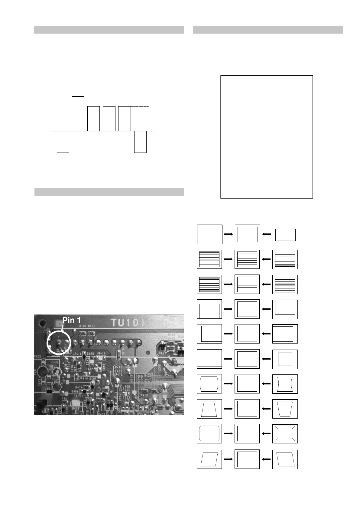
Sub Colour Adjustment
Deflection System Adjustment
1. Receive a PAL colour bar signal.
2. Connect an oscilloscope to Pin 5 of CN003 [A Board].
3. Enter into the ‘Service’ service menu.
4. Adjust the ‘Sub Colour’ data so that the Cyan, Magenta and
Blue colour bars are of equal levels as indicated below.
Same Level
B-Out Wav eform
T uner A GC Adjustment
Note:
There should be no need to adjust the A GC as this is preadjusted during manufacture of the FRONTEND. If the AGC
does need adjustment then follow steps 1. to 4. below.
1. Receive a signal of 62dBuV / 75 ohm terminated via the tuner
antenna socket.
2. Connect a voltmeter to pin1 of TU101 [print side of A Board]
or to the AGC pin of CN001 [mount side of A Board].
3. Confirm that the A GC v oltage is 3.5v olts +/- 0.3volts.
4. If adjustment is required, then re-adjust the A GC variable
resistor (located at the top rear of the FRONTEND) to obtain
a voltage of 3.5V +/- 0.3V.
1. Enter into the ‘Geometry’ service menu.
2. Select and adjust each item in order to obtain the optimum image.
YRTEMOEG
ytiraeniL-V
llorcS-V
klBH-tfeL
klBH-thgiR
elgnA-V
woB-V
ertneC-H
eziS-H
pmA-niP
niP-renroC-U
niP-renroC-L
esahPniP
epolS-V
eziS-V
noitcerroC-S
ertneC-V
mooZ-V
atnegaM
)36,0(
)36,0(
)51,0(
)51,0(
)36,0(
)36,0(
)36,0(
)36,0(
)36,0(
)36,0(
)36,0(
)36,0(
)36,0(
)36,0(
)36,0(
)36,0(
)36,0(
)36,0(
jdA
23
8
6
jdA
jdA
jdA
jdA
jdA
jdA
jdA
jdA
53
jdA
jdA
jdA
32
04
V SIZE
V LIN
S CORRECTION
[ Print side of A board ]
V CENTRE
H CENTRE
H SIZE
PIN AMP
PIN PHASE
CORNER PIN
V ANGLE
19
Page 20
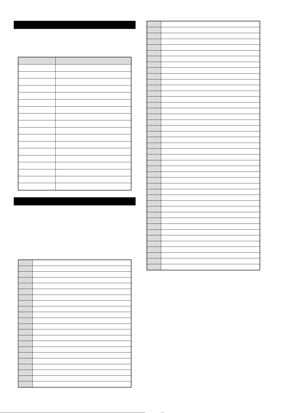
4-2. TEST MODE 1:
T est Mode 1 is av ailable by pressing the ‘TEST’ b utton once, OSD
‘T’ appears. The functions described below are available by selecting
the indicated keys. The ‘T’ is released automatically after each
command is executed.
YEK NOITCNUFEDOM-T
+emulovmumixamemulov
-emulovmuminimerutciP
+erutcipmumixamerutciP
-erutcipmuminimerutciP
puruolocmumixamruoloc
nwodruolocmuminimruoloc
thgirb-ssenthgirbmumixamssenthgirb
krad-ssenthgirbmuminimssenthgirb
hsilprup-euhhsilprup-euh
hsineerg-euhhsineerg-euh
prahs-ssenprahsmumixamssenprahs
tfos-ssenprahsmuminimssenprahs
tfelecnalabtfelllufecnalab
thgirecnalabthgirllufecnalab
puelbertmumixamelbert
nwodelbertmuminimelbert
pussabmumixamssab
nwodssabmuminimssab
4-3. TEST MODE 2:
T est Mode 2 is av ailable by pressing the ‘TEST’ button twice, OSD
‘TT’ appears. The functions described below are available by
selecting the two numbers. To release the ‘Test mode 2’, press 00, 10,
20 ... twice or switch the TV set into Stand-by mode. In ‘TT Menu’
mode, it is possible to remove the Menu from the screen by pressing
the Speaker Off button once. Pressing the Speaker OFF button a
second time will cause the Menu to reappear. The function is kept
even when the menu is not displayed on screen !!.
00
10
20
30
40
50
60
70
80
11
21
31
41
51
61
91
12
22
32
42
52
62
ffoedom'TT'
mumixamerutciP
muminimerutciP
%53otemuloVenohpdaeh/rekaepsteS
%05otemuloVenohpdaeh/rekaepsteS
%56otemuloVenohpdaeh/rekaepsteS
%08otemuloVenohpdaeh/rekaepsteS
edomgniegA
noitidnoCgnippihS
tnemtsujdaerutcipbuS
tnemtsujdaruolocbuS
tnemtsujdassenthgirBbuS
tnemtsujdanoitisoPHtxeT
tseTlioCnoitatoR
%05levelerutciP
elbasiD/elbanEedoMyrotcaF
RKEDAnoitanitseD
LBnoitanitseD
RKEDAnoitanitseD
UnoitanitseD
RKEDAnoitanitseD
LBnoitanitseD
72
82
13
33
53
63
83
14
34
44
54
64
84
94
15
25
45
55
65
75
16
26
36
46
56
66
76
86
96
17
27
37
47
87
97
78
98
19
29
39
49
59
99
RKEDAnoitanitseD
RKEDAnoitanitseD
elbasiD/elbanEffotuhSotuA
FFO/NOnoitatoR
sutatsVTyalpsiD;9:61><3:4TRC
tsetNO/FFO)MV(noitaludoMyticoleV
tnemtsujda2G
MVNesilaitini-eR
dnuosAlauDtceleS
dnuosBlauDtceleS
dnuosonoMtceleS
dnuosoeretStceleS
nigrivnonsaMVNteS
nigrivsaMVNteS
ffo/noybloDlautriV
elbanE)tnemecnahnessaB(BPM/refoowbuS
RKEDAnoitani)partamorhc(M/CerutcurtstoD
)SPLA/YNOS(noitcelesrenuT
elbasid/elbaneEBB
elbasid/elbaneenilunemEBB
tnemtsujdACGAotuA
elbasid/elbanednabesabmorfMA
rotcennoc3CYelbasiD/elbanE
ytiroirpBGRelbasiD/elbanE
elbasid/elbanetceted-otuaBGR
elbasid/elbaneremitnO
tnemtsujdACGAlaunaM
)melborpN(erusaemretnuoc62XelbasiD/elbanE
erutaefICAelbasiD/elbanE
oedivLAPecroF
)noitidnocoedivlamronerotser(LAPecrof-nU
)47.6/5.6(metsys2K/DnotiewZelbanE
)47.5/5.6(metsys3K/DnotiewZelbanE
tfelllufecnalaB
thgirllufecnalaB
tsetsyeklacoL
godhctawelbasiD/elbanE
edommooz9:41teS
edommoozTRAMSteS
edommooz9:61teS
edomMOOZteS
edommooz3:4teS
unememiTgnikroWdnarorrEyalpsiD
20
Page 21
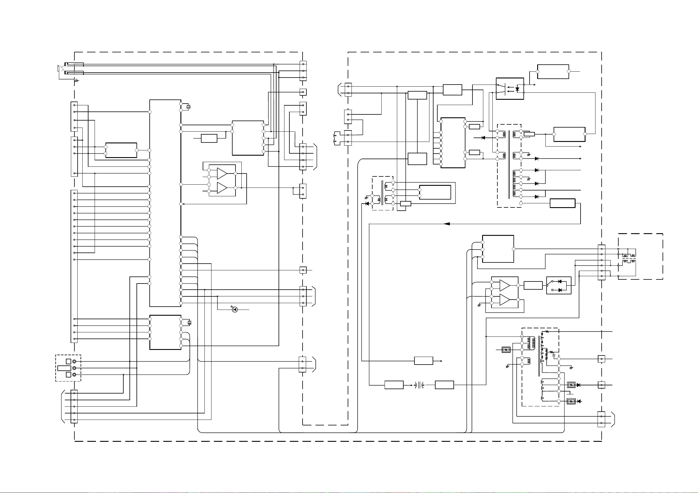
5-1. BLOCK DIAGRAMS (1)
LOWB
5
6
4
CN001
J401
(1/2)
77
63
5
7
4
3
2
1
5
4
RELAY
SWITCH
Q601
T603
SRT
16
15
17
18
18
16
1
2
15
8
11
12
IC602
ERROR AMP
1
2
PH601
ISOLATOR
+B
D638
RECT
AUDIO
VCC
+B
LOWB
3.3V REG
H-OUT
Q533
STBY
+3.3V
IC608
7
5
IC501
V OUTPUT
3
1
VD+
BOOST
REF
OUT
PIN OUT
Q532
6
5
4
3
2
1
T511
FBT
FV
ABL
12
3
4
5
6
13
8
9
11
10
7
V DY
V- DY+
DY ASSY
V- DY-
H DY
H- DY+
H- DY-
V- DY+
V- DY-
H- DY+
H- DY+
TO C BOARD
CN707
H1
200V
TO PICTURE
TUBE
2
3
65+
-
+
-
1
7
IC531
PIN CORRECTION
EWD
HP
PROTECT
IN
VP
VD-
41
2
3
T531
HDT
IC609
STANDBY
POWER
HD
C
D
T602
D632
RECT
IC001
MICRO, VIDEO PRO CESSOR,
ROM, AUDIO, VIDEO SWITCH
CN606
CN510
VD
VG(H)
VS
+B
HV
CN508
XTAL OUT
NVM WP
L AUDIO
TO SPEAKERS
A ( )
POWER SUPPLY, DEFLECTI ON,
SMALL SIG NAL BOARD,
AUDIO AMPLI FIER
IC601
D514
-15V RECT
VIDEO
L
1
2
1
3
DGC
DGC
DGC
DGC
CHECK
DGC CHECK
CN603
CN602
2
1
H- DY-
H- DY-
TO VM BOARD
CN1702
IC604
DUAL DC REGULATOR
2
1
+8V
D608
RELAY
RY601
MAIN RECT
D601
1
3
4
6
7
8
CT
VSENSE
RT
TIMER
SS
VCI
12
VG(L)
Q606
Q607
6
5
4
7
3
LOWB
D624
D618
D619
VM VCC
QCP DETECT
Q602,603.604
1
4
CN1201
R AUD O
64
XTAL IN
40
AUDIO MUTE
5
AUD OUT
78
+3.3V
STBY
6
5
23+
-
+
-
7
1
+5V STBY
IC1201
AUDIO AMP
MUTE
1
IN/INL
10
3
/OUT W
H-DRIVE
Q535
68
IC401
AV LINK
+5V STBY
69
A10
B10
EWD 17
VD-
18
VD+
19
ABL
54
74
TO C BOARD
CN1705
7
J401
(2/2)
NSC CORRECT
ROT COL
AGC
SCL
SDA
VIDEO
IC004
SDA
6
SCL
5
7
WP
71
SCL
72
SDA
28
CVBS2/
CVBSY2
3
AGC
53
B2/UIN
1
MODE1
80
MODE2
52
G2/YIN
51
R2/VIN
38
-/C4
50
INSSW2
32
CVBS1
37
-/CVBS4Y4
45
AUDIO 1
49
AUDIO 3
34
CVBS3
A8
A11
A7
B8
A15
A16
B20
B15
A20
A2
BLUE IN
MODE1
MODE2
GREEN N
RED IN
C2 IN
BLK
V IN 1
Y/V IN 2
TU101
MUTE SW
Q212
AUDIO
AUD O
VIDEO
STBY
70
2
FB
D513
+15V RECT
1
3
D625
14
OUT/L
12
/OUT R
9
STBY/
MW
6
/IN W
L OUT
L IN
R IN
R OUT
TO H5 BOARD
CN5102
CN1200
1
CN1202
CN1203
WOOFER
WFR R IN
WFR L IN
1
2
4
MUTE
7
SDA
CS
SCL
AGC
IC201
MSP3410D-PP-B4
SC1 OUT
R
37
SC1 OUT L
36
63
XTAL OUT
62
XTAL IN
47
SC3 IN R
46
SC3 IN L
31
DACM SUB
/C3 35
KEY 2
LED
6
SIRCS
67
CN405
KEY
LED
SIRCS
TO H5 BOARD
CN5100
A1
B1
A3
B3
SC1 OUT L
SC1 OUT R
SC2 OUT L
SC2 OUT R
SC2 OUT
R
34
SC2 OUT L
33
R
AUD O
J402
L
CVBS/Y
KEY
R
A19
VIDEO
CN406
TO H5 BOARD
CN5101
1
4
6
8
9
6
5
3
2
C
CS
4
6
7
TO F5 BOARD
CN5603
9
OCP
TO D2 BOARD
CN8801
SW
SMART
CN512
DEF SW 75
2
6
J1200
D614
MAIN RECT
1
DF
CN509 TAP (CONTACT)
3
H SYNC
CN503
21 22
Page 22

5-1. BLOCK DIAGRAMS (2)
3
CN1702
TO
A BOARD
CN501
QP OUT
Q1841
72
IC1902
DF/DQP/TIMING
+
-
3
1
2
+
-
5
7
6
3
TO
A BOARD
CN503
+9V
IC1901
COMPARATOR
CN1809
1
DF
15V PULSE
D4 ( )
DYNAMIC FOCUS AND DQP
CN1701
2
1
V PULSE
VM Board
C Board
A Board
H5 Board
D2 Board
D4 Board
F5 Board
TO A BOARD
CN504
TO A BOARD
CN405
TO A BOARD
CN406
TO A BOARD
CN1200
CN703
CN5100
CN5101
CN5102
R
1
G
2
B
3
IK
6
7
NS CORRECT
R IN
KR
3
1
2
5
+8V
7
G IN
KG
9
B IN
KB
8
IK
IC701
IC1801
-
6
7
+
5
2
+
1
-
3
C ( )
ROT -
ROT +
RGB OUT
RCV
R
G
B
H1
G2
CN1801
3
TO
ROTATION
1
COIL
H
PICTURE TUBE
C
2
V
TO BOARD
T511 (FBT)
G4G
H
V
CN5601
CN5602
AB (CONTACT)
AC IN
LIGHTENING
AC OUT
AC INPUT,
F5 ( )
POWER SWITCH
FUSE
TO A BOARD
CN606
5-2. CIRCUIT BOARD LOCATION
5-3. SCHEMATIC DIAGRAMS AND
PRINTED WIRING BOARDS
Note :
• All capacitors are in µF unless otherwise noted.
Reference Information
RESISTOR RN
RC
FPRD
FUSE
RS
RB
RW
COIL LF-8L
CAPACITOR TA
PS
PP
PT
MPS
MPP
ALB
ALT
ALR
: METAL FILM
: SOLID
: NON FLAMMABLE CARBON
: NON FLAMMABLE FUSIBLE
: NON FLAMMABLE METAL OXIDE
: NON FLAMMABLE CEMENT
: NON FLAMMABLE WIREWOUND
: ADJUSTMENT RESISTOR
: MICRO INDUCTOR
: TANTALUM
: STYROL
: POLYPROPYLENE
: MYLAR
: METALIZED POLYESTER
: METALIZED POLYPROPYLENE
: BIPOLAR
: HIGH TEMPERATURE
: HIGH RIPPLE
• pF : µµF 50WV or less are not indicated except for
electrolytic types.
• Indication of resistance, which does not have one for
rating electrical power, is as follows.
2
4
6
7
1
2
6
9
6
5
3
2
1
STBY 5V
KEY
LED
SIRCS
KEY
C
L
R
L IN
L OUT
R OUT
R IN
HP PLUGGED
FUNCTION
SWITCH
S5101-S5106
Q5101
Q5100
IC5100
1
2
J5100
S
4 3
2
V
L
R
J5101
H5 ( )
AV3 INPUT SIRCS
TO A BOARD
CN512
CN8801
HDY-
SMART CORR
SWITCH
CN8802
SWITCH
Pitch : 5mm
Note :
Electrical power rating : 1/4W
• Chip resistors are 1/10W
• All resistors are in ohms.
k = 1000 ohms, M = 1000,000 ohms
• : nonflammable resistor.
Note :
• : fusible resistor.
• : internal component.
8
6
• : panel designation or adjustment for repair.
• All variable and adjustable resistors have
characteristic curve B, unless otherwise noted.
SWITCH
Q8804,Q8805
2
1
8V
1
3
8V
SWITCH
Q8802
1
3
SWITCH
Q8801
24
IC8801
SMART MODE
DEFLECTION
SMART MODE
D2 ( )
SWITCH
• All voltages are in Volts.
• Readings are taken with a 10Mohm digital mutimeter.
• Readings are taken with a color bar input signal.
• Voltage variations may be noted due to normal production
tolerences.
•: B + bus.
• : B - bus.
The components identified by shading
and marked are critical for safety.
Replace only with the part numbers
specified in the parts list.
Les composants identifiés par une trame et
par une marque sont d'une importance
critique pour la sécurité. Ne les remplacer
que par des pièces de numéro spécifié.
specified.
• : RF signal path.
CN1702
TO
A BOARD
CN503
CN1701
TO
A BOARD
CN501
• : earth - ground.
• : earth - chassis.
GND
Q.P.-
Q.P.+
VM
CN1718
1
2
3
4
Q.P.
VM
QP-
135V
10
VM
8
135V
1
VM AMP
Q1701, 1702, 1703
VM BUFFER
Q1704, 1705
VM OUT
Q1708, 1711
NECK ASSY
VM ( )
VELOCITY MODULATION
23 24
Page 23
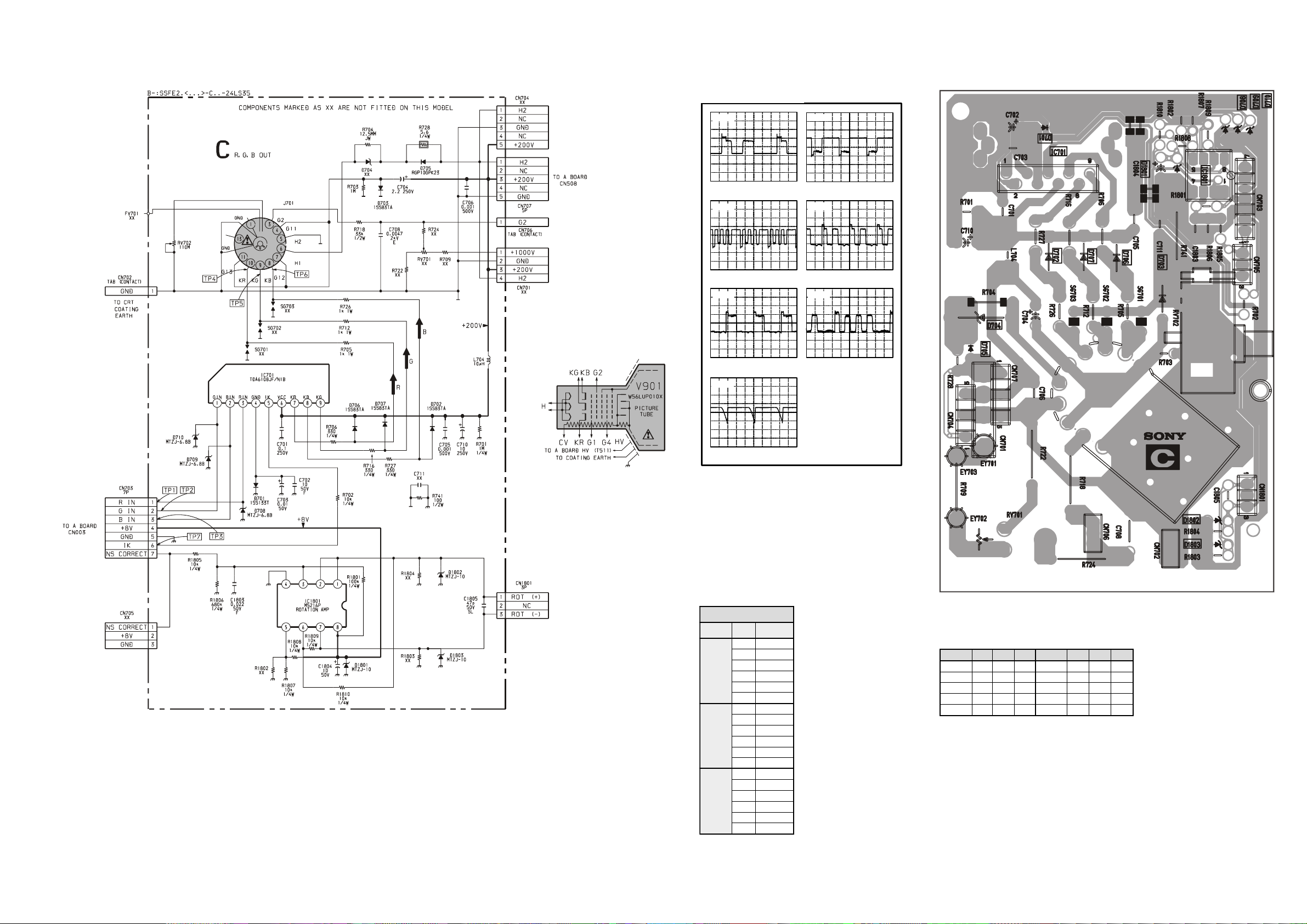
elbaTegatloVCI
oNfeR
oNniP )V(egatloV
0035CI
19.3
38.3
54.8
70.351
80.751
90.251
5235CI
19.3
38.3
57.8
70.051
80.551
90.051
0535CI
19.3
38.3
54.8
70.051
80.651
90.941
feR )e( )b( )c( feR )e( )b( )c(
1035Q5.38.20 0035Q7.34.48.3
6235Q6.330 5235Q7.34.48.3
2535Q7.330 1535Q8.34.49.3
5735Q3.019.01110535Q119.019.3
6735Q113.019.01
0u dv 0 div
0u dv 5u div
0u dv
0 div
u div
117 Vp-p (H) 109 Vp-p (H)
109 Vp-p (H)
2.5 Vp-p (H) 2.5 Vp-p (H)
TP1 TP2
TP3
3.64 Vp-p (H)
2.5 Vp-p (H)
TP4
TP5 TP6
TP7
C Board Waveforms
IC Voltage Table
Semiconductor Voltage Ta ble
C [ R,G,B OUT ]
25 26
Page 24
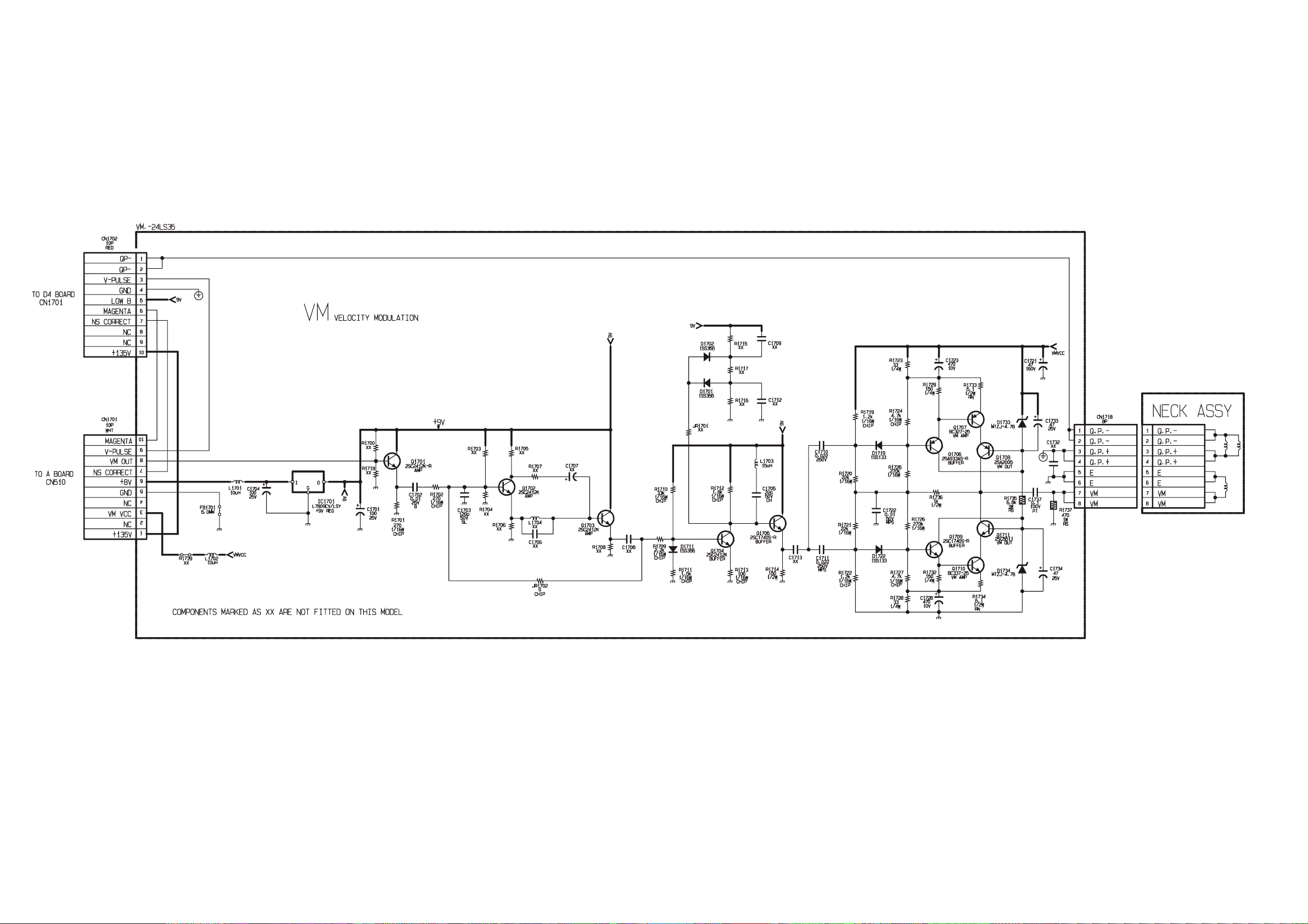
VM[ VELOCITY MODULATION ]
27 28
Page 25
29 30
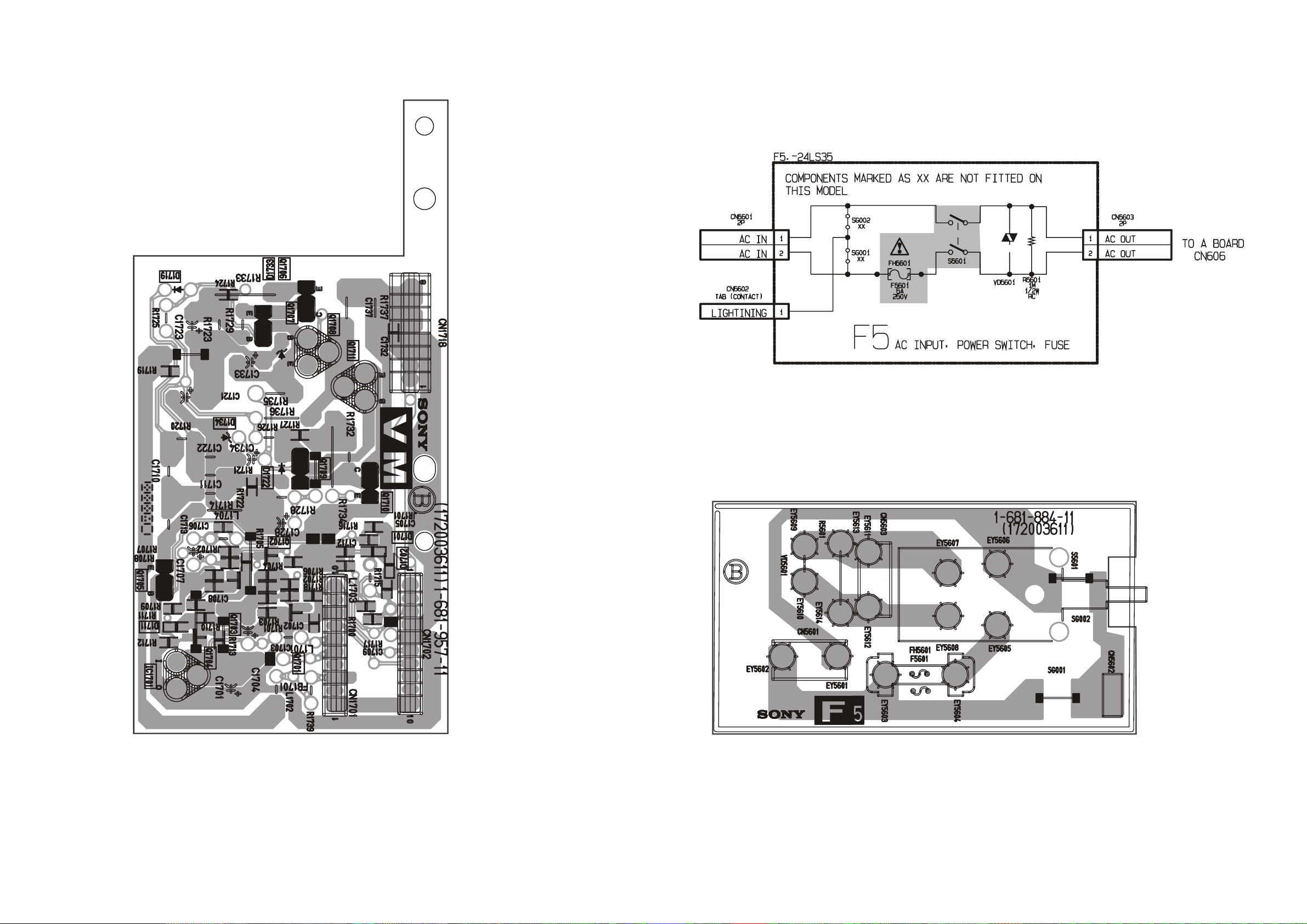
F5[ AC INPUT , POWER SWITCH, FUSE ]VM[ PRINTED WIRING BOARD ]
Page 26
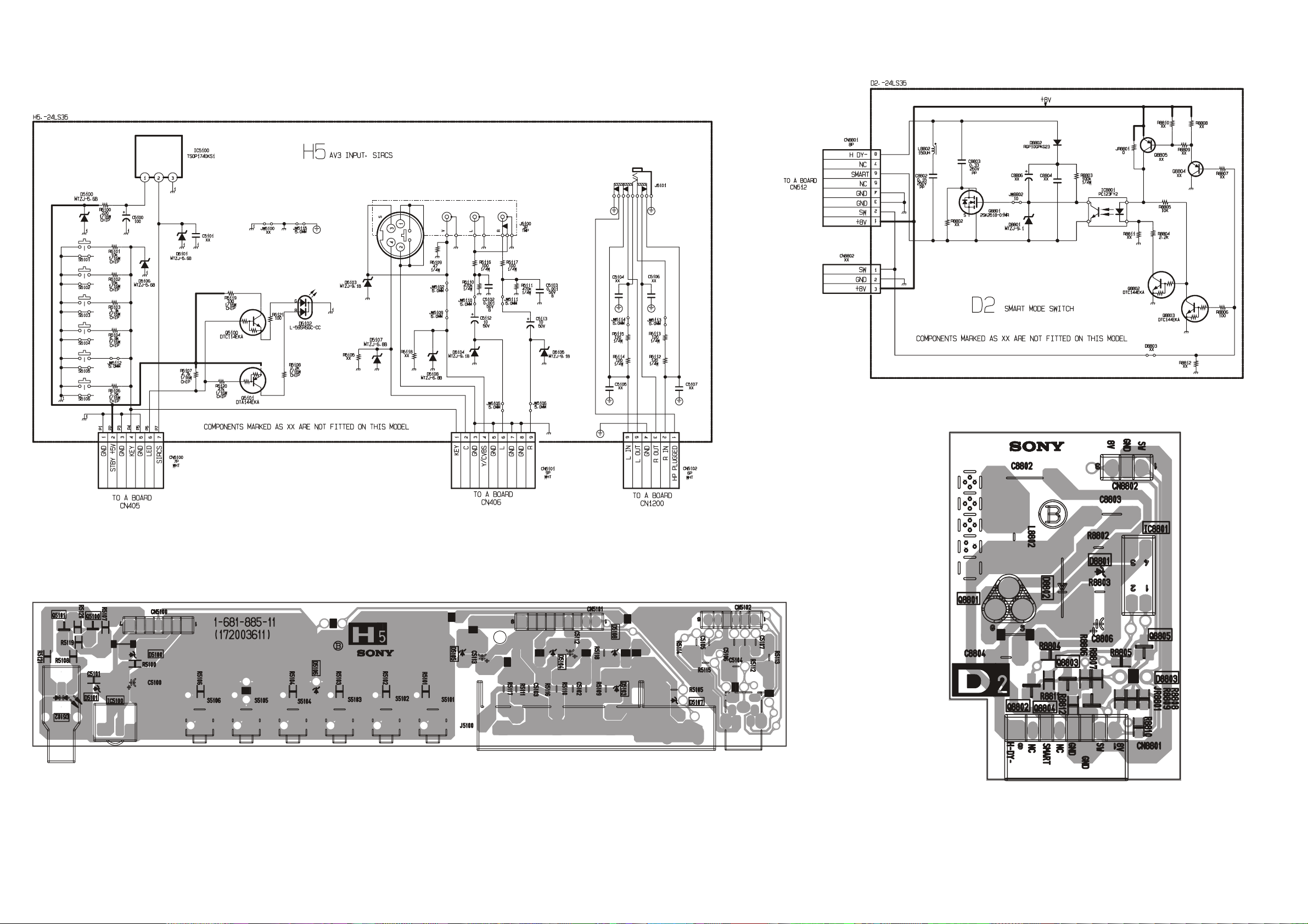
H5 [ AV3 INPUT, SIRCS ] D2 [ SMART MODE SWITCH ]
31 32
Page 27
33 34
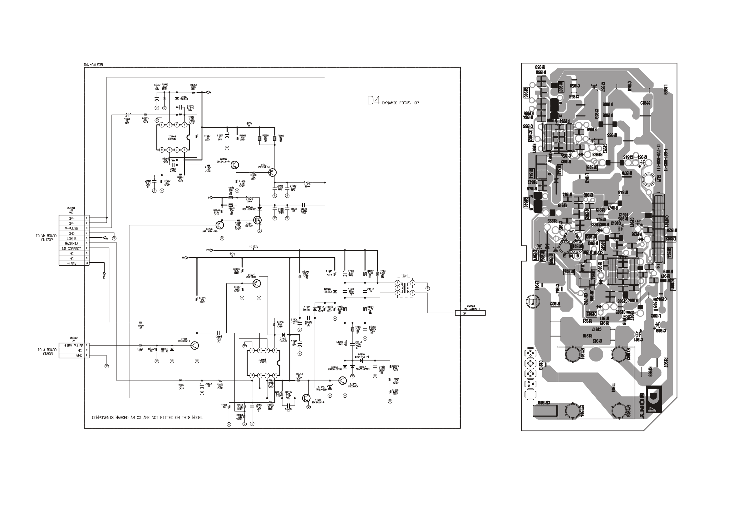
D4 [ DYNAMIC FOCUS, QP ]
Page 28
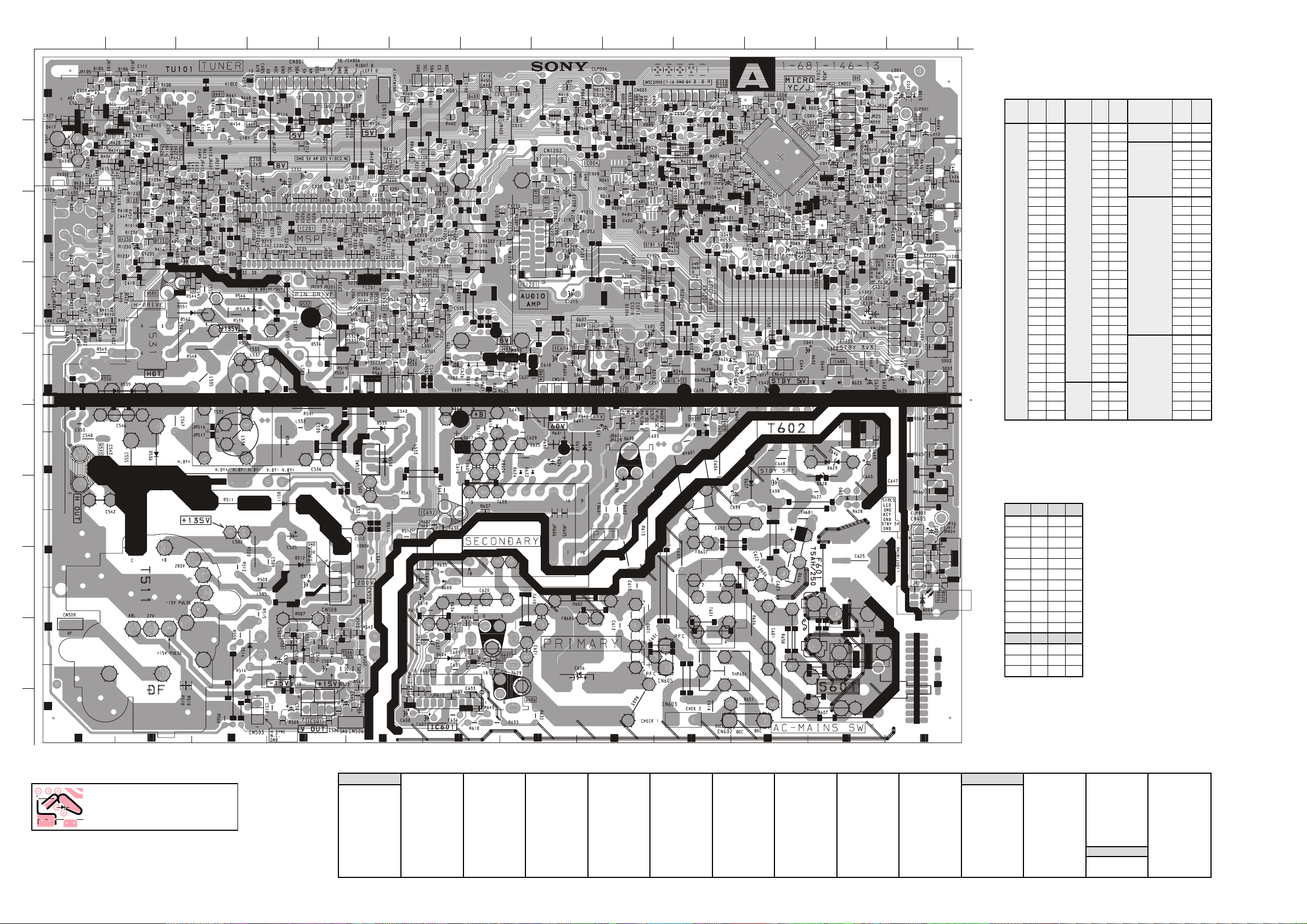
NOTE:
Portions of the circuit marked as shown are high
voltage areas. Use care to prevent electric shock
during inspection or repair.
ABCDE F
G
HIJKLM
1
2
3
4
5
6
7
8
9
10
EDOID
310D1-M301D1-E632D3-D114D3-C424D2-M505D2-M835D6-E216D5-G526D6-H
ROTSISNART
235Q4-D906Q6-J400CI2-H
100D2-I610D2-J401D2-E932D3-D214D3-D724D4-A605D4-D935D5-B316D6-J726D7-K310Q3-I335Q6-A0121Q3-H104CI3-I
200D3-I810D3-I501D1-A204D3-E314D3-C824D3-C705D2-M145D5-F416D8-K826D7-L410Q1-L535Q4-B1121Q3-H105CI01-E
300D2-K020D8-M601D1-B304D2-B414D2-B924D3-D215D8-D375D5-F516D5-H926D7-L940Q3-J106Q5-K0321Q3-B135CI4-F
400D4-M120D2-L701D2-B404D3-I814D3-B534D2-A315D9-D106D9-I816D6-H136D7-L202Q3-E206Q5-G1321Q3-B106CI01-F
600D8-M220D2-J702D3-F504D2-B914D2-E634D2-A415D9-C206D5-J916D6-H236D5-K302Q2-F306Q5-G2321Q3-B206CI7-F
700D1-K530D3-K012D5-I604D2-B024D2-B105D9-D435D5-E406D9-F026D5-M336D5-L212Q5-I406Q5-H3321Q2-C406CI5-H
800D3-L630D3-K112D5-I704D2-B124D2-C205D9-D535D6-E806D8-F126D5-J836D6-I104Q1-C606Q01-G
S'CI
806CI5-L
010D2-G150D3-L212D5-I804D2-B224D2-C305D2-I635D6-B016D5-J226D7-H046D5-L904Q1-G706Q9-G100CI2-K906CI6-L
110D2-F101D1-B822D4-E014D2-C324D2-C405D2-I735D4-C116D5-G326D5-J114Q2-D806Q6-J200CI8-M1021CI4-H
IC V oltage T able
oNfeR
niP
oN
stloV
)V(
feR
oN
niP
oN
stloV
)V(
feR
oN
niP
oN
stloV
)V(
100CI
10
100CI
052.0
105CI
69.31
22.3155.273.0
39.2255.2
135CI
14.1
50 355.223.2
60.2451.238.1
83.2552.554.2
90.8650.366.1
010.5751.374.6
210 851.3
106CI
14.08-
310 952.325.08-
410.4260 3 2.08-
614.1360 4 2.08-
715.1460 5 5.18810 560 6 6.18910 768.478.77-
028.3864.098.18-
128.3960 0167-
220.5070 119.18620 170 214.97-
825.3270 415.61
926.3371.75111
039.1470.5614.41
133.0571.8814.68
236.3675.3-
1021CI
111
439.1770 3 9.4
534.1872.350
639.3972.360
838.1080 7 3.11
043.3
105CI
14.193.0
243.323.2010
344.138.1210
540 54.24153.11
feR )e( )b( )c(
310Q07.00
610Q003.3
212Q07.00
104Q8.42.48.1
114Q1.17.12.4
106Q6.58.43.5
206Q2.411.58
306Q880
406Q005.2
806Q006.5
906Q6.56.50
feR )s( )g( )d(
606Q9.015.417.68
706Q4.28-9.97-9.01
535Q05.22.59
Semiconductor
Voltage Table
A [ PRINTED WIRING BOARD ]
Semiconductor Location T able
35 36
Page 29
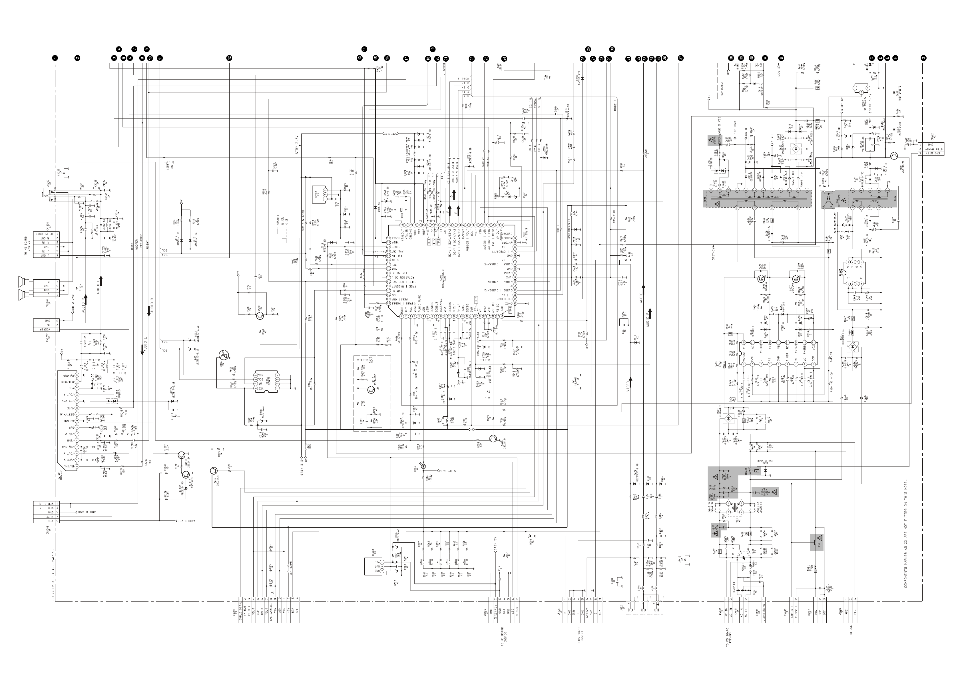
KV-24LS35
[9-927-408-01]
37 38 39
A [ POWER SUPPLY , DEFLECTION, A UDIO AMPLIFIER (P age 1/2) ]
Page 30
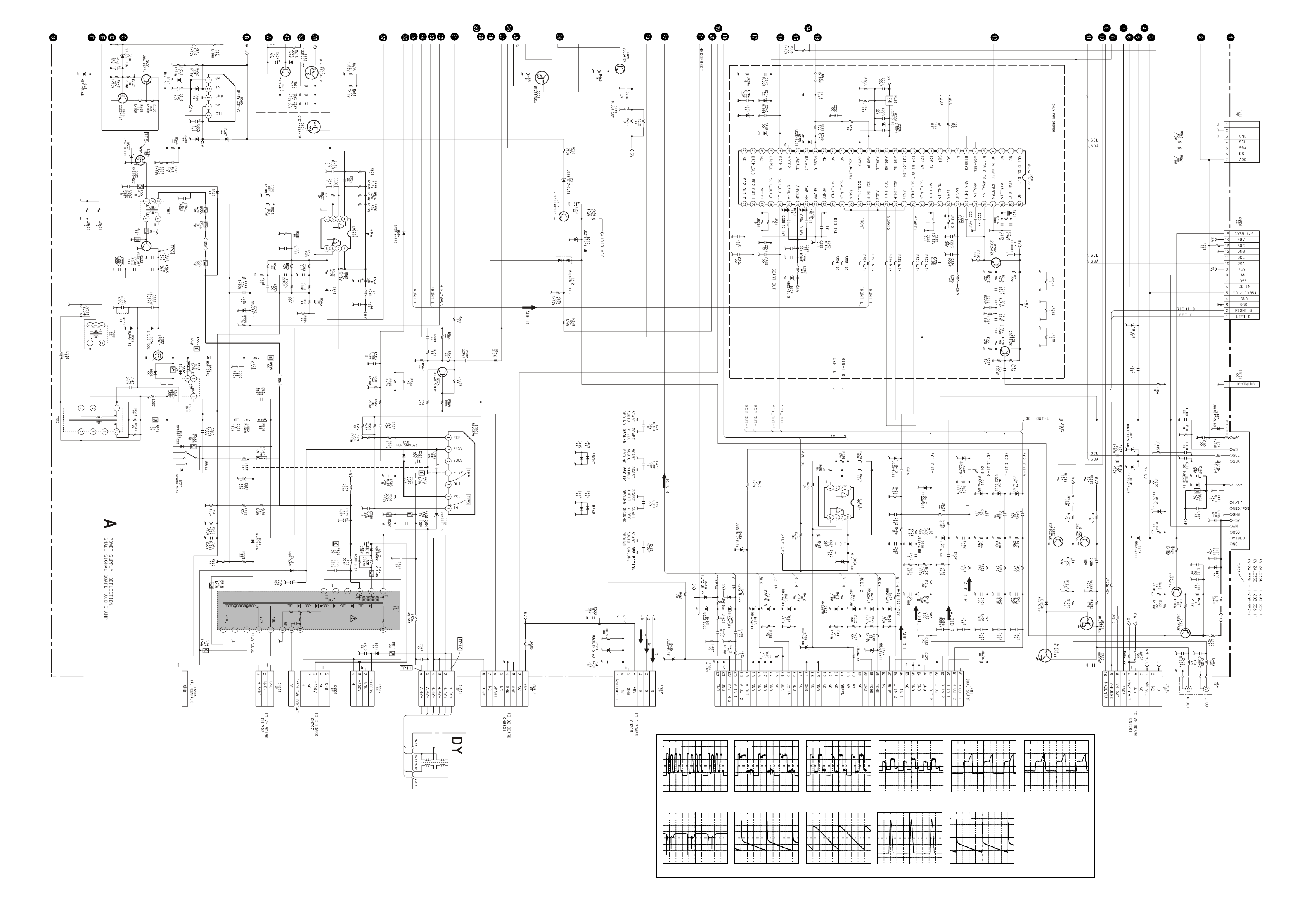
A Board Waveforms
1.83 Vp-p (V)
2 v
TP7
2 v
1.88 Vp-p (H)
TP1
m v
TP8
488 mVp-p (V)
2 v
1.86 Vp-p (H)
TP3
2 v
1.84 Vp-p (H)
TP2
2 v
6.0 Vp-p (H)
TP4
2 v
5.4 Vp-p (H)
TP5
2 v
TP6
16.8 Vp-p (H)
m v
50.8 Vp-p (V)
TP11
m v
49.8 Vp-p (V)
TP9
2 v
TP10
1.06 kVp-p (H)
A [ POWER SUPPLY , DEFLECTION, A UDIO AMPLIFIER (P age 2/2) ]
40 41 42
Page 31
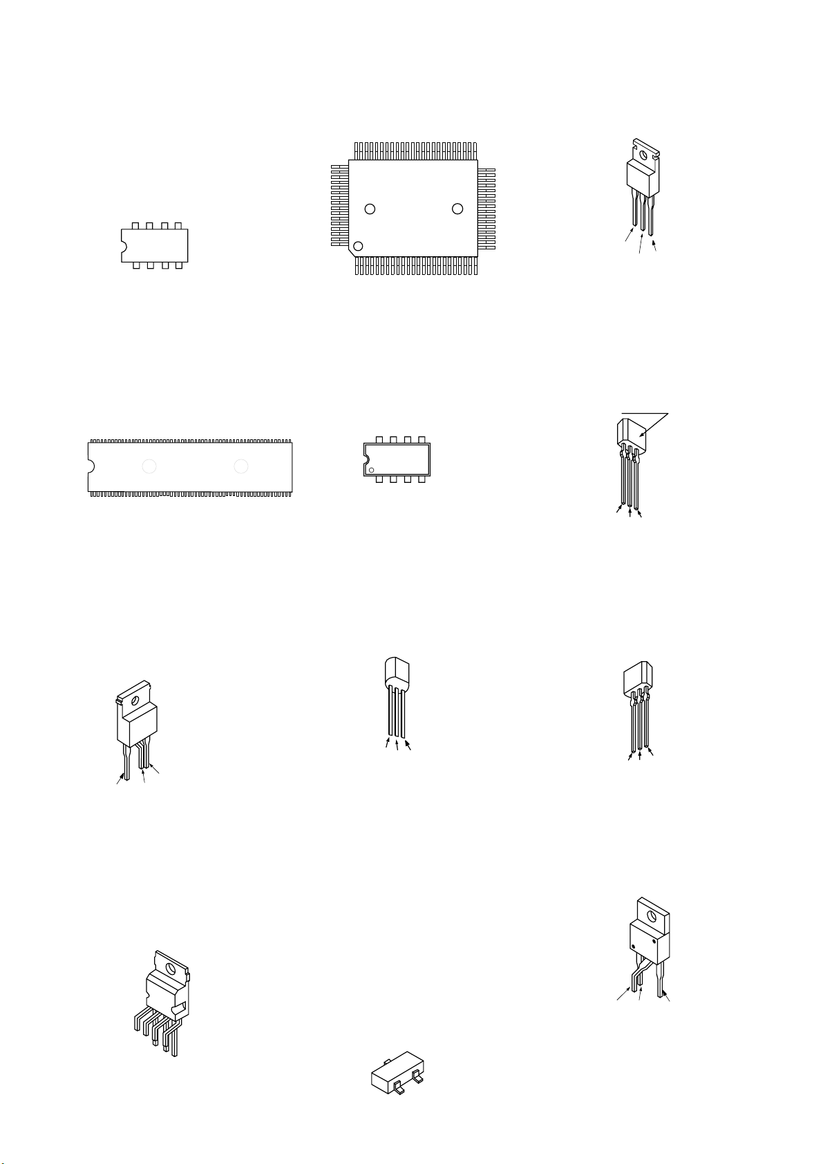
5-4. SEMICONDUCTORS
LM358N
TDA9394H
LM393DT
LM393N
M5216P
TDA2822M
TEA2124
7
6
8
1
2
3
( TOP VIEW )
5
4
MSP3411G-PP-B9
3364
132
64
65
80
1
( MARKING S DE V EW )
TOP209P
( TOP VIEW )
IRF614-005
IRF614-037
41
40
25
24
IRF620
B
E
C
2SA933AS-QT
2SAG33ASQT
2SA933AS-RT
2SC1740S-RT
2SC2785-HFE
LETTER SIDE
E
C
B
SE-135N
SE135N-LF4
1
STV9379
1
BF421-AMMO
2SA1091-O
E
C
B
3
1V
2V
3 GND
OUT
IN
2
DTA144ESA
DTA144ESA
DTC114ESA
2SC2785-HFE
E
2SK2518-01MR
2SK2251-01-F19
2SK2640-01MR
B
C
DTC114EKA-T146
DTC143TKA-T146
DTC144EKA-T-146R
R2SA1162-G
2SA1037AK-T146
2SC1623-L5L6
2SD601A-Q-TX
2SC1623-L5-L6
2SC2412K-QR
7
2SC2412K-T-146-QR
E
B
C
C
43
Page 32
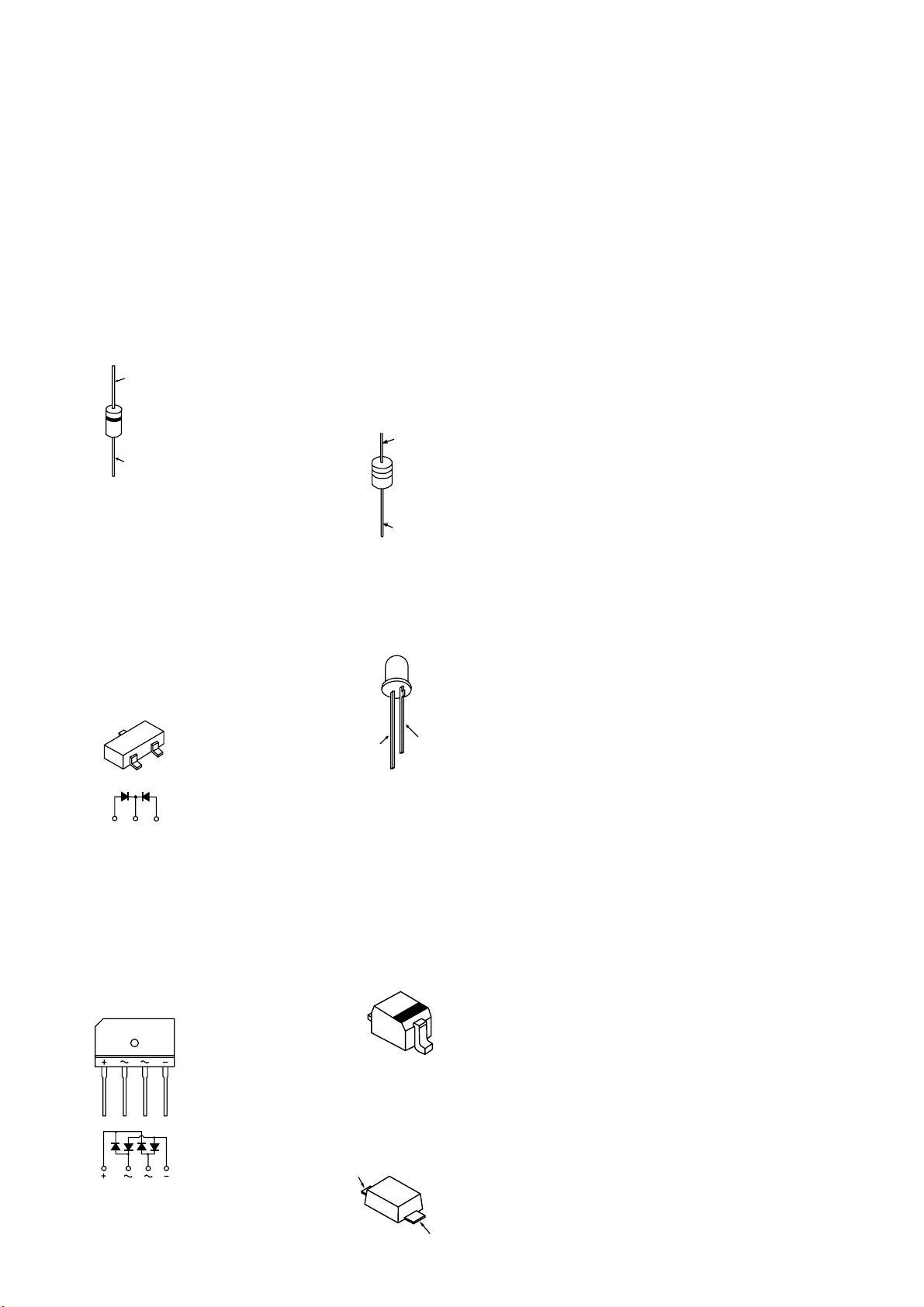
AK04-V1
AU-01Z-V1
BYD33G
BYD33G-AMMO
DINL20-TA
D1NL20U
DINL40-U-TR2
ERB44-06TP1
EGP20G
EG-1Z-V1
EL1Z
ERD28-06S
CATHODE
ANODE
ERD28-06S
ERC06-15S
FMN-G12S
GP08D
RGP10GPKG23
RG15GPKG23
RG1CLF-B1
RU-3AM
RU3YX-LF-C4
RU3YX-V1
RU-4AM-T3
1SS292T-77
ERA38-06
ERA81-004TP1
ERA83-006
MTZJ-3.6A
MTZJ-T-77-2.2A
HZS9.1NB2
MTZJ-T-77-3.6B
MTZJ-4.7C
MTZJ-T-77-5.1B
MTZJ-T-77-5.6B
MTZJ-T-77-6.8A
MTZJ-T-77-8.2B
MTZJ-7.5B
MTZJ-T-77-9.1A
MTZJ-T-77-9.1B
MTZJ-T-77-10
MTZJ-T-72-10A
MTZJ-T-72-10B
MTZJ-T-77-15B
MTZJ-T-77-33A
MTZJ-33C
MTZJ-7.5B
P6KE200ASY
RD3.6ES-B2
RD3.9ES-B2
RD5.1ESB2
RD5.6ESB2
RD6.8ES-B2
RD7.5ESB2
RD9.1ES-B3
RD10ESB2
RD15ESB2
1SS119-25
1SS133T-77
CATHODE
ANODE
DAN202K
DAN202K-T146
MA8330-TX
DTZ33B
3
2
D4SB60L
SLA-570KT3F
1
2
3
1
ANODE
CATHODE
1SS355TE-17
DTZ-TT11-6.8B
RD12SB2
UDZS-TE-17-4.7B
UDZSTE-175.6B
UDZSTE-176.8B
UDZSTE-179.1B
UDZ-TE-17-22B
ANODE
UF4005PKG23
ANODE
CATHODE
CATHODE
44
Page 33
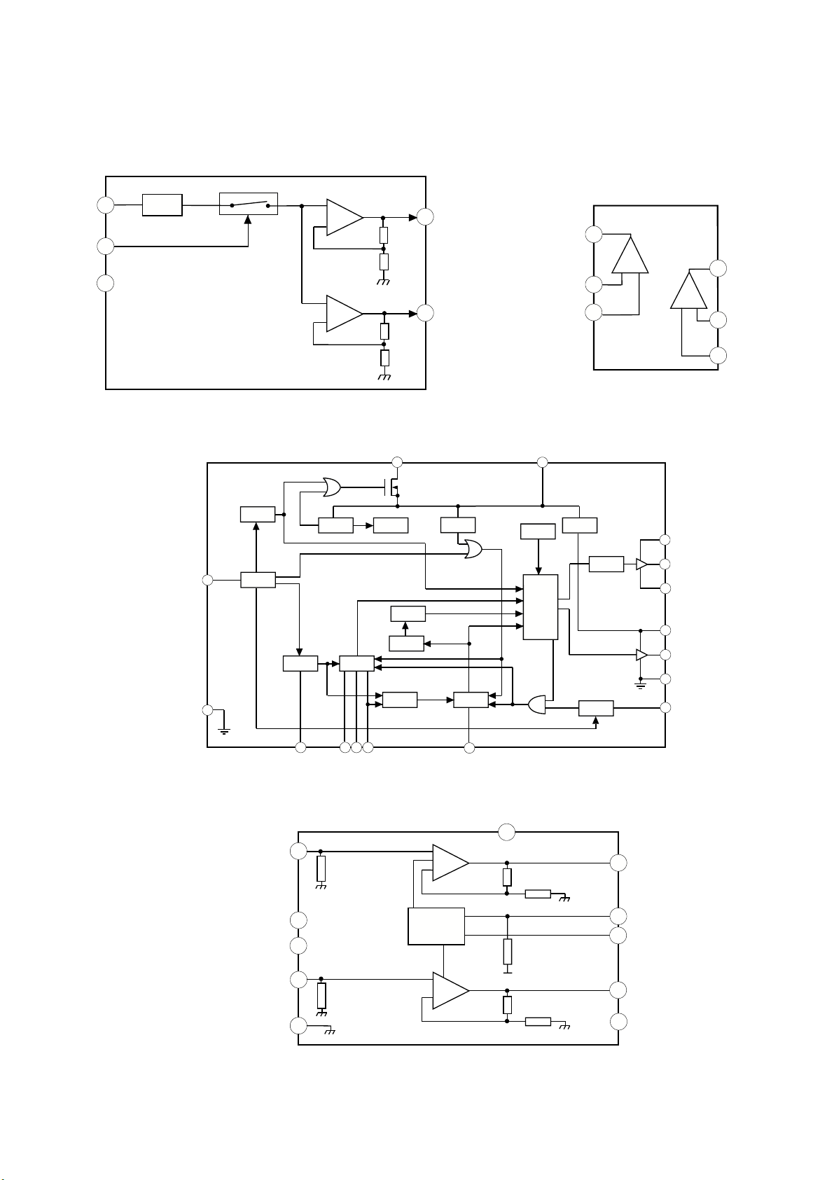
5-5 IC BLOCK DIAGRAMS
A BOARD IC604 BA41W12ST-V5
SW
2
Vref
-
+
1
A BOARD IC401/IC531 LM393DT
1
5
-
+
3
GND
-
+
4
2
3
7
-
+
6
5
A BOARD IC601 MCZ3001D
18
Remote
1
Vsense
5
SS
DVLD
15v/8v
Osc
Internal
ref 5v
Centre
F/B
Latch
OFF
Sel=34v
Timer
8
TSD
Control
Logic
Driver
Reg. 10v
OCP
Level
Shift
14
16
15
10
12
11
9
7
4 3 2
A BOARD IC1201 TDA7497
1
8
11
5
7
Sgn Gnd
Pwr Gnd
+
-
MUTE/STBY
PROTECTION
+
-
45
6
13
Vss
14
9
60K
10
12
Pwr
15
Gnd
Page 34
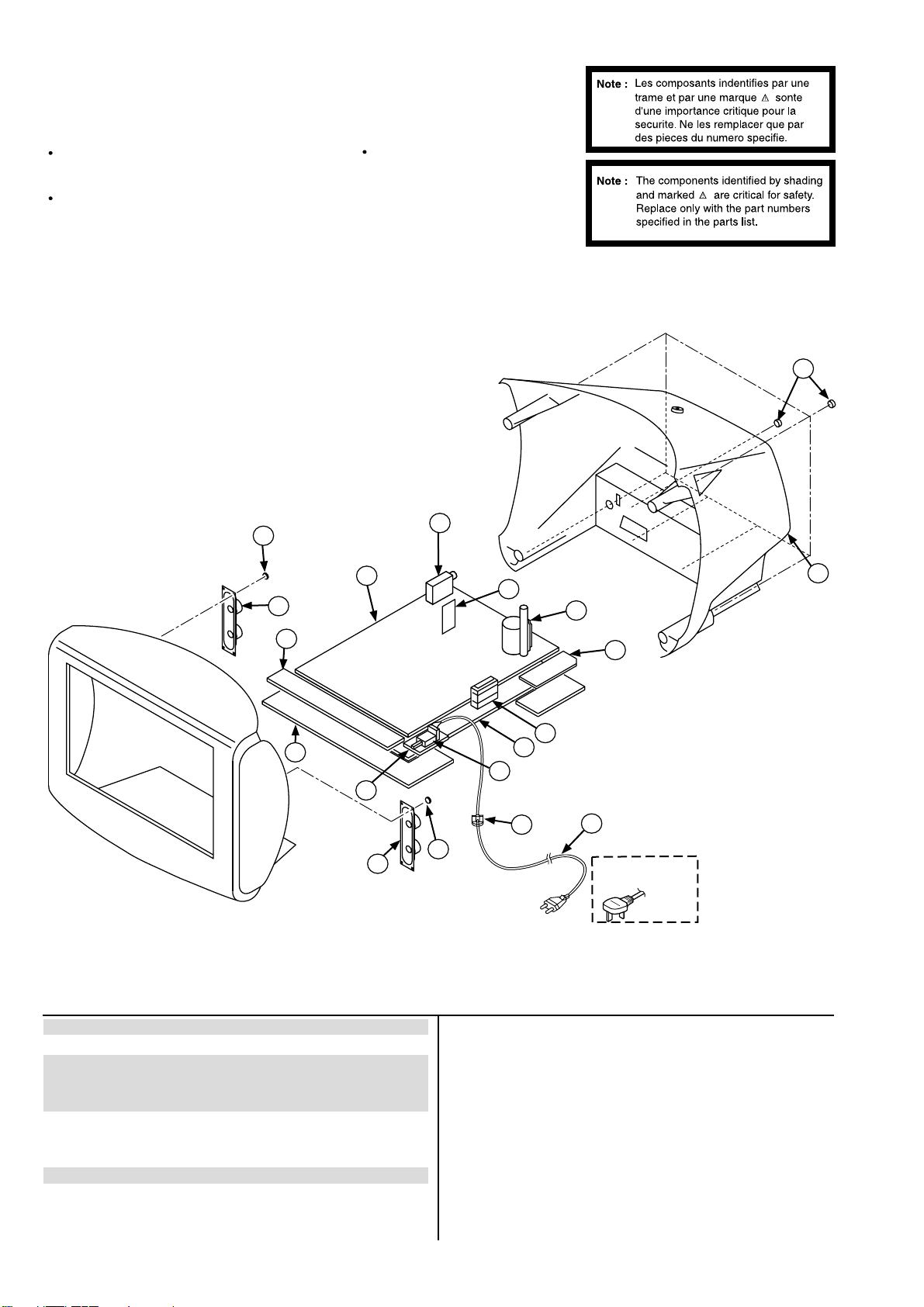
NOTE :
SECTION 6
EXPLODED VIEWS
Items with no part number and no description are not
stocked because they are seldom required for routine
service.
The construction parts of an assembled part are indicated
with a collation number in the remarks column.
6-1. CHASSIS
17
16
Items marked “*” are not stocked
since they are seldom required for
routine service. Some delay should
be anticipated when ordering these
items.
9
10
8
15
14
7
11
12
5
13
17
16
4
1
2
6
3
UK Models
only
REF.NO. PART.NO DESCRIPTION REMARK REF.NO. PART.NO DESCRIPTION REMARK
1 £ 1-571-433-21 SWITCH, PUSH (AC POWER)
2 *4-202-531-01 AC CORD LOCK (SC)
3 £ 1-783-083-11 CORD, POWER (WITH FILTER)
(KV-24LS35B/24LS35E)
£ 1-776-204-12 CORD, POWER (FILTER) (KV-24LS35U)
4 *4-206-048-21 BRACKET, MAIN
5 1-419-893-11 COIL, CHOKE 26MMH
6 *A-1640-434-A D4 BOARD, COMPLETE
7 £ 1-453-372-11 TRANSFORMER ASSY, FLYBACK (NX4521//Z2B14)
8 *A-1642-282-A D2 BOARD, COMPLETE
9 1-693-555-11 TUNER STEREO (KV-24LS35B)
1-693-557-11 TUNER STEREO (KV-24LS35U)
10 *A-1632-943-A A BOARD, COMPLETE (KV-24LS35B)
*A-1632-944-A A BOARD, COMPLETE (KV-24LS35E)
*A-1632-935-A A BOARD, COMPLETE (KV-24LS35U)
11 *A-1646-244-A H5 BOARD, COMPLETE
12 *4-206-154-01 H & F BRACKET
13 *A-1624-105-A F5 BOARD, COMPLETE
14 4-206-064-01 COVER, REAR
15 4-039-358-01 SCREW (4x16), (+) BV TAPPING
16 1-529-408-11 SPEAKER (4.2x24CM)
17 4-384-096-01 SCREW (4x16), BV TAPPING, +P
1-693-556-11 TUNER STEREO (KV-24LS35E)
46
Page 35
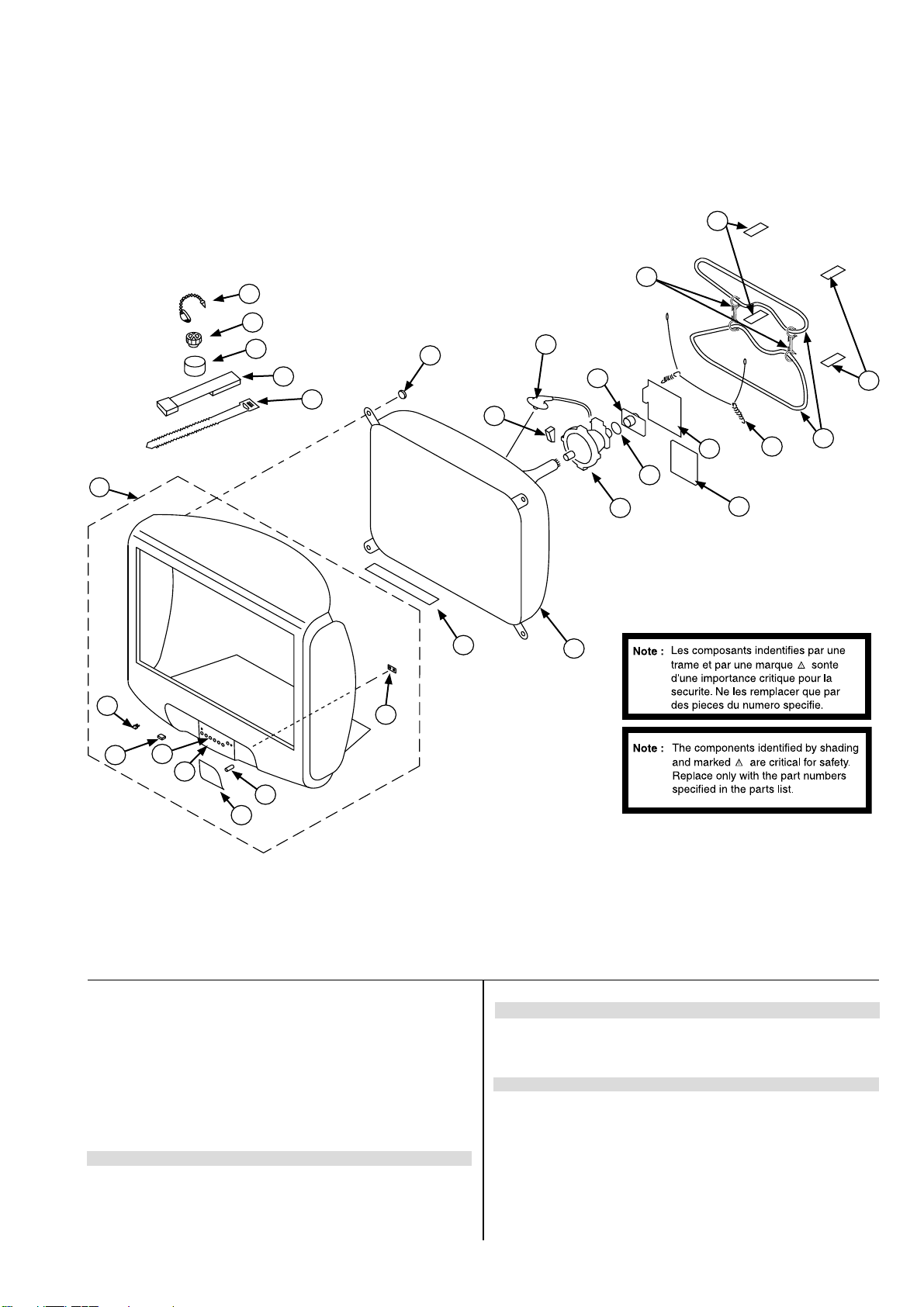
6-2. PICTURE TUBE
73
74
75
76
77
72
71
70
69
68
64
67
65
67
66
51
52
53
54
55
56
57
58
59
60
61
62
63
REF.NO. PART.NO DESCRIPTION REMARK REF.NO. PART.NO DESCRIPTION REMARK
51 X-4200-735-1 BEZNET ASSY 52-58
52 4-047-464-01 CATCHER, PUSH
53 4-202-555-01 SHAFT DOOR
54 4-205-376-01 MULTI BUTTON
55 4-205-550-01 COVER MULTI BUTTON
56 4-206-153-01 POWER BUTTON
57 4-202-964-11 SPRING
58 4-205-375-01 GUIDE, LIGHT
59 4-203-128-41 SHEET, BLOTTING
60 £ 8-733-008-05 PICTURE TUBE (W56LUP010X)
61 8-451-529-11 DEFLECTION YOKE (Y24REA)
62 1-452-896-11 COIL, NA ROTATION (RT-200)
63 *A-1644-122-A VM BOARD, COMPLETE
65 4-200-433-01 SPRING, EXTENSION
66 £ 1-424-800-11 COIL, DEGAUSSING
67 *4-203-390-21 CUSHION, DGC
68 4-064-883-03 HOLDER, DGC
69 8-453-011-11 NECK ASSY, (NA299-M)
70 £ 1-251-317-63 CAP ASSY, HIGH VOLTAGE
71 3-078-658-01 SPACER, DY
72 4-036-188-01 SCREW, SELF TAPPING
73 4-308-870-00 CLIP, LEAD WIRE
74 1-452-094-00 MAGNET, ROTATABLE DISK; 15MM
75 1-452-032-00 MAGNET, DISK; 10MM
76 X-4387-214-1 PERMALLOY ASSY, CORRECTION
77 3-701-007-00 BAND, BINDING
64 *A-1638-160-A C BOARD, COMPLETE
47
Page 36

SECTION 7
ELECTRICAL PARTS LIST
PARTS LISTING TABLE OF CONTENTS
Page
A BOARD COMMON Parts List : Parts common to all models listed in this manual ..................... 49
A BOARD VARIANT Parts List : Parts that belong only to the model specifi ed
Model
KV-24LS35B ............................................................................................. 56
KV-24LS35E ............................................................................................. 56
KV-24LS35U ............................................................................................. 56
C BOARD COMPLETE Parts List : ............................................................................................. 56
VM BOARD COMPLETE Parts List : ............................................................................................. 57
F5 BOARD COMPLETE Parts List : ............................................................................................. 58
H5 BOARD COMPLETE Parts List : ............................................................................................. 58
D2 BOARD COMPLETE Parts List : ............................................................................................. 59
D4 BOARD COMPLETE Parts List : ............................................................................................. 59
MISCELLANEOUS : ............................................................................................. 61
ACCESSORIES AND PACKAGING MATERIALS : ........................................................................................ 61
Note : Refer to the designated variant parts list when seeking a part indicated by an asterisk (*)
Parts indicated (XX) on the Schematic Diagram are not used in this model and
therefore do not appear in the Parts List.
48
Page 37

REF.NO. PART.NO DESCRIPTION REMARK REF.NO. PART.NO DESCRIPTION REMARK
*A-1632-943-A A Board, Complete (KV-24LS35B)
*A-1632-944-A A Board, Complete (KV-24LS35E)
*A-1632-935-A A Board, Complete (KV-24LS35U)
A Board Common Parts
C106 1-126-933-11 ELECT 100UF 20.00% 16V
C112 1-162-970-91 CERAMIC CHIP 0.01UF 10.00% 25V
C204 1-115-340-11 CERAMIC CHIP 0.22UF 10.00% 25V
C211 1-162-970-91 CERAMIC CHIP 10000PF 10.00% 50V
C213 1-163-249-11 CERAMIC CHIP 82PF 5.00% 50V
A
1-900-900-22 LEAD ASSY, FOCUS
4-382-854-01 SCREW (M3X8), P, SW (+)
< CAPACITOR >
C002 1-163-233-91 CERAMIC CHIP 18PF 5.00% 50V
C004 1-163-037-11 CERAMIC CHIP 0.022UF 10.00% 50V
C005 1-126-926-91 ELECT 1000UF 20.00% 10V
C006 1-163-233-91 CERAMIC CHIP 18PF 5.00% 50V
C009 1-164-004-11 CERAMIC CHIP 0.1UF 10.00% 25V
C010 1-164-005-11 CERAMIC CHIP 0.47UF 16V
C011 1-163-005-91 CERAMIC CHIP 470PF 10.00% 50V
C012 1-126-963-11 ELECT 4.7UF 20.00% 50V
C013 1-162-970-11 CERAMIC CHIP 0.01UF 10.00% 25V
C014 1-162-970-11 CERAMIC CHIP 0.01UF 10.00% 25V
C015 1-162-970-11 CERAMIC CHIP 0.01UF 10.00% 25V
C016 1-216-295-91 SHORT 0
C018 1-162-970-11 CERAMIC CHIP 0.01UF 10.00% 25V
C019 1-162-919-11 CERAMIC CHIP 22PF 5.00% 50V
C020 1-164-004-11 CERAMIC CHIP 0.1UF 10.00% 25V
C021 1-163-037-11 CERAMIC CHIP 0.022UF 10.00% 50V
C022 1-126-935-11 ELECT 470UF 20.00% 10V
C025 1-126-935-11 ELECT 470UF 20.00% 16V
C026 1-162-970-11 CERAMIC CHIP 0.01UF 10.00% 25V
C027 1-164-004-11 CERAMIC CHIP 0.1UF 10.00% 25V
C028 1-163-009-91 CERAMIC CHIP 0.001UF 10.00% 50V
C030 1-163-009-91 CERAMIC CHIP 0.001UF 10.00% 50V
C033 1-163-009-91 CERAMIC CHIP 0.001UF 10.00% 50V
C035 1-163-009-91 CERAMIC CHIP 0.001UF 10.00% 50V
C036 1-163-009-91 CERAMIC CHIP 0.001UF 10.00% 50V
C037 1-136-244-01 FILM 0.1UF 2.00% 50V
C038 1-163-038-91 CERAMIC CHIP 0.1UF 25V
C039 1-164-505-11 CERAMIC CHIP 2.2UF 16V
C040 1-163-017-00 CERAMIC CHIP 0.0047UF 10.00% 50V
C042 1-162-625-11 CERAMIC CHIP 0.0047UF 5.00% 50V
C043 1-163-037-11 CERAMIC CHIP 0.022UF 10.00% 50V
C044 1-164-346-11 CERAMIC CHIP 1UF 16V
C045 1-164-489-11 CERAMIC CHIP 0.22UF 10.00% 16V
C046 1-163-037-11 CERAMIC CHIP 0.022UF 10.00% 50V
C047 1-126-935-11 ELECT 470UF 20.00% 16V
C053 1-164-004-11 CERAMIC CHIP 0.1UF 10.00% 25V
C055 1-126-960-11 ELECT 1UF 20.00% 50V
C100 1-126-933-11 ELECT 100UF 20.00% 16V
C103 1-126-965-91 ELECT 22UF 20.00% 50V
C105 1-162-970-91 CERAMIC CHIP 0.01UF 10.00% 25V
C214 1-163-139-00 CERAMIC CHIP 820PF 5.00% 50V
C215 1-163-084-00 CERAMIC CHIP 1.5PF 0.25PF 50V
C216 1-163-117-00 CERAMIC CHIP 100PF 5.00% 50V
C217 1-163-084-00 CERAMIC CHIP 1.5PF 0.25PF 50V
C218 1-163-249-11 CERAMIC CHIP 82PF 5.00% 50V
C221 1-163-109-00 CERAMIC CHIP 47PF 5.00% 50V
C222 1-163-117-00 CERAMIC CHIP 100PF 5.00% 50V
C223 1-126-965-91 ELECT 22UF 20.00% 50V
C224 1-163-117-91 CERAMIC CHIP 100PF 5.00% 50V
C225 1-126-157-11 ELECT 10UF 20.00% 16V
C226 1-164-004-11 CERAMIC CHIP 0.1UF 10.00% 25V
C227 1-163-117-91 CERAMIC CHIP 100PF 5.00% 50V
C228 1-126-965-91 ELECT 22UF 20.00% 50V
C229 1-163-017-00 CERAMIC CHIP 0.0047UF 10.00% 50V
C230 1-164-336-11 CERAMIC CHIP 0.33UF 25V
C232 1-126-157-11 ELECT 10UF 20.00% 16V
C233 1-164-004-11 CERAMIC CHIP 0.1UF 10.00% 25V
C234 1-107-823-11 CERAMIC CHIP 0.47UF 10.00% 16V
C235 1-164-005-11 CERAMIC CHIP 0.47UF 25V
C236 1-126-157-11 ELECT 10UF 20.00% 16V
C237 1-126-965-91 ELECT 22UF 20.00% 50V
C238 1-163-117-91 CERAMIC CHIP 100PF 5.00% 50V
C239 1-126-157-11 ELECT 10UF 20.00% 16V
C242 1-163-009-91 CERAMIC CHIP 0.001UF 10.00% 50V
C245 1-163-009-91 CERAMIC CHIP 0.001UF 10.00% 50V
C401 1-126-964-11 ELECT 10UF 20.00% 50V
C404 1-162-970-91 CERAMIC CHIP 0.01UF 10.00% 25V
C405 1-163-009-91 CERAMIC CHIP 1000PF 10.00% 50V
C407 1-164-346-11 CERAMIC CHIP 1UF 16V
C408 1-127-715-91 CERAMIC CHIP 0.22UF 10% 16V
C409 1-126-964-11 ELECT 10UF 20.00% 50V
C410 1-162-970-91 CERAMIC CHIP 0.01UF 10.00% 25V
C411 1-163-009-91 CERAMIC CHIP 0.001UF 10.00% 50V
C412 1-164-346-11 CERAMIC CHIP 1UF 16V
C414 1-164-346-11 CERAMIC CHIP 1UF 16V
C415 1-164-346-11 CERAMIC CHIP 1UF 16V
C416 1-126-964-11 ELECT 10UF 20.00% 50V
C417 1-162-970-91 CERAMIC CHIP 0.01UF 10.00% 25V
C418 1-164-346-91 CERAMIC CHIP 1UF 16V
C419 1-162-964-11 CERAMIC CHIP 0.001UF 10.00% 50V
C423 1-127-715-91 CERAMIC CHIP 0.22UF 10% 16V
C424 1-163-009-91 CERAMIC CHIP 0.001UF 10.00% 50V
C426 1-163-009-91 CERAMIC CHIP 0.001UF 10.00% 50V
C427 1-163-009-91 CERAMIC CHIP 0.001UF 10.00% 50V
C428 1-163-009-91 CERAMIC CHIP 0.001UF 10.00% 50V
49
Page 38
A
REF.NO. PART.NO DESCRIPTION REMARK REF.NO. PART.NO DESCRIPTION REMARK
C429 1-163-009-91 CERAMIC CHIP 0.001UF 10.00% 50V
C430 1-102-114-00 CERAMIC 470PF 10.00% 50V
C435 1-163-017-00 CERAMIC CHIP 0.0047UF 10.00% 50V
C436 1-163-017-00 CERAMIC CHIP 0.0047UF 10.00% 50V
C437 1-164-346-11 CERAMIC CHIP 1UF 16V
C438 1-164-346-11 CERAMIC CHIP 1UF 16V
C445 1-126-964-11 ELECT 10UF 20.00% 50V
C446 1-126-964-11 ELECT 10UF 20.00% 50V
C447 1-162-970-91 CERAMIC CHIP 0.01UF 10.00% 25V
C449 1-216-025-91 RES CHIP 100 5% 1/10W
C501 1-126-968-11 ELECT 100UF 20.00% 50V
C502 1-163-038-91 CERAMIC CHIP 0.1UF 25V
C503 1-115-832-91 ELECT 100UF 20.00% 50V
C504 1-106-220-00 MYLAR 0.1UF 10.00% 100V
C505 1-137-194-81 FILM 0.47UF 5.00% 50V
C506 1-162-970-91 CERAMIC CHIP 0.01UF 10.00% 25V
C507 1-162-970-91 CERAMIC CHIP 10000PF 10.00% 25V
C509 1-107-364-11 MYLAR 0.01UF 10.00% 400V
C510 1-163-005-91 CERAMIC CHIP 470PF 10.00% 50V
C513 1-107-662-11 ELECT 22UF 20.00% 250V
C515 1-104-666-11 ELECT 220UF 20.00% 25V
C517 1-115-781-91 ELECT 220UF 20.00% 25V
C518 1-106-375-12 MYLAR 0.022UF 10.00% 250V
C519 1-163-275-11 CERAMIC CHIP 0.001UF 5.00% 50V
C520 1-163-038-91 CERAMIC CHIP 0.1UF 25V
C600 £ 1-119-888-51 CERAMIC 2200PF 20.00% 250V
C601 £ 1-136-516-12 FILM 0.1UF 20.00% 300V
C602 £ 1-136-516-12 FILM 0.1UF 20.00% 300V
C603 £ 1-119-899-51 CERAMIC 1000PF 10.00% 250V
C604 £ 1-119-899-51 CERAMIC 1000PF 10.00% 250V
C605 1-111-036-91 ELECT 470UF 20.00% 16V
C606 1-117-751-11 ELECT(BLOCK) 220UF 20.00% 450V
C607 1-126-964-11 ELECT 10UF 20.00% 50V
C608 1-126-963-11 ELECT 4.7UF 20.00% 50V
C610 1-126-941-11 ELECT 470UF 20.00% 25V
C611 1-163-009-91 CERAMIC CHIP 0.001UF 10.00% 50V
C612 1-104-571-91 CERAMIC 0.0015UF 10.00% 2KV
C613 1-104-571-91 CERAMIC 0.0015UF 10.00% 2KV
C614 1-161-964-51 CERAMIC 0.0047UF 250V
C615 1-115-339-11 CERAMIC CHIP 0.1UF 10.00% 50V
C616 1-165-127-11 CERAMIC 470PF 10.00% 500V
C617 1-165-127-11 CERAMIC 470PF 10.00% 500V
C618 1-126-949-11 ELECT 220UF 20.00% 35V
C619 1-164-644-11 CERAMIC 330PF 10.00% 500V
C620 1-137-990-21 FILM 33000PF 3.00% 800V
C621 1-164-644-11 CERAMIC 330PF 10.00% 500V
C622 1-104-571-91 CERAMIC 0.0015UF 10.00% 2KV
C623 1-104-571-91 CERAMIC 0.0015UF 10.00% 2KV
C624 1-126-935-11 ELECT 470UF 20.00% 16V
C626 1-126-967-11 ELECT 47UF 20.00% 50V
C522 1-130-495-00 MYLAR 0.1UF 5.00% 50V
C524 1-163-037-11 CERAMIC CHIP 0.022UF 10.00% 50V
C525 1-123-024-21 ELECT 33UF 160V
C531 1-126-964-11 ELECT 10UF 20.00% 50V
C532 1-163-037-11 CERAMIC CHIP 0.022UF 10.00% 50V
C533 1-164-690-91 CERAMIC CHIP 2200PF 5.00% 50V
C536 1-117-665-21 FILM 0.33UF 5.00% 250V
C537 1-102-002-91 CERAMIC CHIP 680PF 10.00% 500V
C538 1-165-319-11 CERAMIC CHIP 0.1UF 50V
C539 1-111-230-11 ELECT 1UF 20.00% 160V
C540 1-136-205-11 MYLAR 0.022UF 10.00% 400V
C541 1-106-383-00 MYLAR 0.047UF 10.00% 200V
C542 1-162-134-11 CERAMIC 470PF 10.00% 2KV
C543 1-162-134-11 CERAMIC 470PF 10.00% 2KV
C545 1-164-004-11 CERAMIC CHIP 0.1UF 10.00% 25V
C546 1-130-118-00 FILM 0.051UF 5.00% 400V
C547 1-117-666-11 FILM 0.39UF 5.00% 250V
C548 1-162-134-11 CERAMIC 470PF 10.00% 2KV
C550 1-107-638-11 ELECT 33UF 20.00% 160V
C552 1-102-212-00 CERAMIC 820PF 10.00% 500V
C553 1-137-417-11 MYLAR 0.0047UF 10.00% 200V
C555 1-117-650-11 FILM 18000PF 3.00% 1.2KV
C580 1-162-970-91 CERAMIC CHIP 0.01UF 10.00% 25V
C582 1-163-259-91 CERAMIC CHIP 220PF 5.00% 50V
C583 1-163-009-91 CERAMIC CHIP 0.001UF 10.00% 50V
C627 1-126-964-91 ELECT 10UF 20.00% 50V
C628 1-126-963-11 ELECT 4.7UF 20.00% 50V
C629 1-165-127-11 CERAMIC 470PF 10.00% 500V
C630 1-107-641-11 ELECT 220UF 20.00% 160V
C631 1-126-942-61 ELECT 1000UF 20.00% 25V
C632 1-126-964-11 ELECT 10UF 20.00% 50V
C633 1-163-009-91 CERAMIC CHIP 0.001UF 10.00% 50V
C634 1-128-562-11 ELECT 47UF 20.00% 100V
C635 1-136-165-00 FILM 0.1UF 5.00% 50V
C636 1-136-479-11 FILM 0.001UF 2.00% 50V
C637 1-126-967-11 ELECT 47UF 20.00% 50V
C638 1-107-679-91 ELECT 10UF 20.00% 450V
C639 1-104-665-11 ELECT 100UF 20.00% 25V
C640 1-104-664-11 ELECT 47UF 20.00% 25V
C641 1-115-785-11 ELECT 470UF 20.00% 16V
C642 1-104-665-11 ELECT 100UF 20.00% 25V
C643 1-165-127-11 CERAMIC 470PF 10.00% 500V
C645 1-164-004-11 CERAMIC CHIP 0.1UF 10.00% 25V
C648 1-125-782-91 CERAMIC 4700PF 10.00% 1KV
C649 1-163-038-91 CERAMIC CHIP 0.1UF 25V
C657 1-126-952-11 ELECT 1000UF 20.00% 35V
C1201 1-126-972-11 ELECT 1000UF 20.00% 50V
C1202 1-126-959-91 ELECT 0.47UF 20.00% 50V
C1203 1-535-143-61 LEAD,JUMPER (5.0MM)
C1207 1-126-960-11 ELECT 1UF 20.00% 50V
50
Page 39

REF.NO. PART.NO DESCRIPTION REMARK REF.NO. PART.NO DESCRIPTION REMARK
C1208 1-126-953-11 ELECT 2200UF 20.00% 35V
C1209 1-163-033-91 CERAMIC CHIP 0.022UF 50V
C1210 1-126-960-11 ELECT 1UF 20.00% 50V
C1211 1-163-033-91 CERAMIC CHIP 0.022UF 50V
C1213 1-164-346-91 CERAMIC CHIP 1UF 16V
D018 8-719-109-69 DIODE RD3.6ES-B2
D019 8-719-978-33 DIODE DTZ-TT116.8B
D021 8-719-978-33 DIODE DTZ-TT116.8B
D022 8-719-069-55 DIODE UDZSTE-175.6B
D035 8-719-069-55 DIODE UDZSTE-175.6B
A
C1215 1-126-952-11 ELECT 1000UF 20.00% 35V
C1218 1-109-982-11 CERAMIC CHIP 1UF 10.00% 10V
C1219 1-104-666-11 ELECT 220UF 20.00% 25V
C1221 1-115-339-11 CERAMIC CHIP 0.1UF 10.00% 50V
C1228 1-126-952-11 ELECT 1000UF 20.00% 35V
C1229 1-163-001-11 CERAMIC CHIP 220PF 10.00% 50V
C1230 1-163-001-11 CERAMIC CHIP 220PF 10.00% 50V
C1232 1-115-339-11 CERAMIC CHIP 0.1UF 10.00% 50V
C1235 1-126-960-11 ELECT 1UF 20.00% 50V
C1236 1-126-960-11 ELECT 1UF 20.00% 50V
< CONNECTOR >
CN001 *1-564-508-11 PLUG, CONNECTOR 5P
CN003 *1-564-510-51 PLUG, CONNECTOR 7P
CN405 *1-564-510-11 PLUG, CONNECTOR 7P
CN406 *1-564-512-11 PLUG, CONNECTOR 9P
CN501 1-580-798-11 CONNECTOR PIN (DY)
CN503 *1-564-506-11 PLUG, CONNECTOR 3P
CN506 1-695-915-11 TAB (CONTACT)
CN508 *1-564-508-11 PLUG, CONNECTOR 5P
CN509 1-695-915-11 TAB (CONTACT)
CN510 1-691-771-11 PLUG (MICRO CONNECTOR) 9P
CN512 *1-770-723-11 CONNECTOR, BOARD TO BOARD 8P
CN602 1-508-765-00 PIN, CONNECTOR (5MM PITCH) 3P
CN603 *1-508-786-00 PIN, CONNECTOR (5MM PITCH) 2P
CN605 *1-691-960-11 PIN, CONNECTOR (PC BOARD) 3P
CN606 *1-695-292-11 PIN, CONNECTOR (POWER)
CN1200 *1-564-509-11 PLUG, CONNECTOR 6P
CN1201 *1-564-507-11 PLUG, CONNECTOR 4P
CN1202 *1-564-506-11 PLUG, CONNECTOR 3P
D036 8-719-069-55 DIODE UDZSTE-175.6B
D051 8-719-081-98 DIODE MM3Z6V8T1
D101 8-719-977-81 DIODE DTZ33B
D103 8-719-081-98 DIODE MM3Z6V8T1
D104 8-719-069-55 DIODE UDZSTE-175.6B
D105 8-719-069-55 DIODE UDZSTE-175.6B
D106 8-719-069-55 DIODE UDZSTE-175.6B
D107 8-719-069-55 DIODE UDZSTE-175.6B
D207 8-719-069-60 DIODE UDZSTE-179.1B
D210 8-719-069-55 DIODE UDZSTE-175.6B
D211 8-719-069-60 DIODE UDZSTE-179.1B
D212 8-719-914-43 DIODE DAN202K
D228 8-719-069-55 DIODE UDZSTE-175.6B
D235 8-719-069-55 DIODE UDZSTE-175.6B
D236 8-719-069-60 DIODE UDZSTE-179.1B
D401 8-719-069-57 DIODE UDZSTE-176.8B
D402 8-719-081-98 DIODE MM3Z6V8T1
D403 8-719-978-33 DIODE DTZ-TT116.8B
D404 8-719-109-89 DIODE RD5.6ESB2
D405 8-719-081-98 DIODE MM3Z6V8T1
D406 8-719-081-98 DIODE MM3Z6V8T1
D407 8-719-081-98 DIODE MM3Z6V8T1
D408 8-719-069-57 DIODE UDZSTE-176.8B
D410 8-719-069-57 DIODE UDZSTE-176.8B
D411 8-719-069-57 DIODE UDZSTE-176.8B
D412 8-719-081-98 DIODE MM3Z6V8T1
D413 8-719-069-57 DIODE UDZSTE-176.8B
D414 8-719-081-98 DIODE MM3Z6V8T1
D418 8-719-069-60 DIODE UDZSTE-179.1B
D419 8-719-049-26 DIODE RB721Q
< DIODE >
D001 8-719-069-55 DIODE UDZSTE-175.6B
D002 8-719-069-55 DIODE UDZSTE-175.6B
D003 8-719-109-69 DIODE RD3.6ES-B2
D005 8-719-929-15 DIODE HZS9.1NB2
D006 8-719-109-89 DIODE RD5.6ESB2
D007 8-719-069-55 DIODE UDZSTE-175.6B
D008 8-719-074-43 DIODE BAS316-115
D010 8-719-074-43 DIODE BAS316-115
D011 8-719-074-43 DIODE BAS316-115
D012 8-719-929-15 DIODE HZS9.1NB2
D013 8-719-109-69 DIODE RD3.6ES-B2
D014 1-216-295-91 SHORT 0
D016 8-719-109-89 DIODE RD5.6ESB2
D420 8-719-081-98 DIODE MM3Z6V8T1
D421 8-719-049-26 DIODE RB721Q
D422 8-719-069-57 DIODE UDZSTE-176.8B
D423 8-719-081-98 DIODE MM3Z6V8T1
D424 8-719-069-60 DIODE UDZSTE-179.1B
D427 8-719-082-01 DIODE MM3Z12VT1
D428 8-719-069-57 DIODE UDZSTE-176.8B
D429 8-719-069-57 DIODE UDZSTE-176.8B
D435 8-719-069-60 DIODE UDZSTE-179.1B
D436 8-719-069-60 DIODE UDZSTE-179.1B
D501 8-719-979-85 DIODE EGP20G
D502 8-719-081-90 DIODE PDZ22B-115
D503 8-719-069-55 DIODE UDZSTE-175.6B
D504 8-719-074-43 DIODE BAS316-115
D512 8-719-302-43 DIODE EL1Z
51
Page 40

A
REF.NO. PART.NO DESCRIPTION REMARK REF.NO. PART.NO DESCRIPTION REMARK
D513 8-719-979-85 DIODE EGP20G
D514 8-719-979-85 DIODE EGP20G
D534 8-719-302-43 DIODE EL1Z
D535 8-719-908-03 DIODE GP08D
D536 8-719-945-80 DIODE ERC06-15S
< FILTER >
FL201 1-239-803-11 FILTER, EMI
< IC >
D537 8-719-070-62 DIODE PDZ9.1B-115
D538 8-719-908-03 DIODE GP08D
D539 8-719-312-10 DIODE RU4AM-T3
D541 1-216-295-91 SHORT 0
D573 8-719-082-00 DIODE MM3Z4V7T1
D601 8-719-510-53 DIODE D4SB60L
D602 8-719-911-19 DIODE 1SS119-25
D604 8-719-083-94 DIODE FUF4005
D608 8-719-063-70 DIODE D1NL20U
D610 8-719-110-41 DIODE RD15ES-B2
D611 8-719-991-33 DIODE 1SS133T-77
D612 8-719-991-33 DIODE 1SS133T-77
D613 8-719-911-19 DIODE 1SS119-25
D614 8-719-077-76 DIODE D2SB60A-F04
D615 8-719-929-15 DIODE HZS9.1NB2
D618 8-719-022-97 DIODE D2S4MF
D619 8-719-022-97 DIODE D2S4MF
D620 8-719-109-85 DIODE RD5.1ESB2
D621 8-719-109-89 DIODE RD5.6ESB2
D623 8-719-911-19 DIODE 1SS119-25
D624 8-719-052-91 DIODE D4SBS4-F
D625 8-719-062-39 DIODE D4SBL20UF1
D627 8-719-063-70 DIODE D1NL20U
D628 8-719-083-49 DIODE P6KE200ASY
D629 8-719-083-94 DIODE FUF4005
D631 8-719-921-63 DIODE MTZJ-7.5B
D632 8-719-063-70 DIODE D1NL20U
D633 8-719-109-69 DIODE RD3.6ESB2
D638 8-719-083-92 DIODE YG802C09RF122
D640 8-719-921-63 DIODE MTZJ-7.5B
D1203 8-719-914-43 DIODE DAN202K
D1204 8-719-069-55 DIODE UDZSTE-175.6B
D1205 8-719-081-90 DIODE PDZ22B-115
D1230 8-719-074-43 DIODE BAS316-115
IC001 6-800-338-01 IC TDA9394H/N1/4/0334
IC004 8-759-575-72 IC M24C08-WMN6T
IC201 6-700-411-01 IC MSP3411G-PP-B8
IC401 8-759-665-11 IC LM393DT
IC501 8-759-192-71 IC STV9379
IC531 8-759-665-11 IC LM393DT
IC601 8-759-670-30 IC MCZ3001D
IC602 8-749-016-19 IC SE135N-LF4
IC604 8-759-668-87 IC BA41W12ST-V5
IC608 8-759-591-02 IC L78L33ABZ-AP
IC609 8-759-468-89 IC TOP209P
IC1201 8-759-831-56 IC TDA7497
< JACK >
J401 1-766-296-21 CONNECTOR, DUAL SCART
J402 1-770-329-11 JACK, PIN 3P
J404 1-784-632-11 JACK, PIN 2P
< COIL >
L001 1-408-611-31 INDUCTOR 47UH
L002 1-414-187-31 INDUCTOR 47UH
L004 1-408-611-31 INDUCTOR 47UH
L006 1-408-611-31 INDUCTOR 47UH
L027 1-216-295-91 SHORT 0
L101 1-412-534-41 INDUCTOR 56UH
L102 1-408-611-31 INDUCTOR 47UH
L103 1-412-002-31 INDUCTOR 4.7UH
L104 1-412-002-31 INDUCTOR 4.7UH
L201 1-408-602-31 INDUCTOR 8.2UH
L202 1-408-591-11 INDUCTOR 1UH
L203 1-408-602-31 INDUCTOR 8.2UH
L205 1-408-591-21 INDUCTOR 1UH
L206 1-535-143-61 LEAD, JUMPER (5.0MM)
L207 1-408-591-21 INDUCTOR 1UH
< FERRITE BEAD >
FB601 1-410-397-21 FERRITE 1.1UH
FB602 1-410-397-21 FERRITE 1.1UH
FB603 1-412-911-11 FERRITE 0UH
FB604 1-410-397-21 FERRITE 1.1UH
FB605 1-410-397-21 FERRITE 1.1UH
FB606 1-412-911-11 FERRITE 0UH
FB607 1-412-911-11 FERRITE 0UH
L401 1-410-993-42 INDUCTOR 1UH
L403 1-410-993-42 INDUCTOR 1UH
L404 1-410-993-42 INDUCTOR 1UH
L405 1-535-143-61 LEAD, JUMPER (5.0MM)
L406 1-414-177-31 INDUCTOR 1UH
L410 1-216-025-11 RES-CHIP 100 5% 1/10W
L430 1-412-002-31 INDUCTOR 4.7UH
L446 1-216-295-91 SHORT 0
L448 1-216-295-91 SHORT 0
L501 1-414-187-11 INDUCTOR 47UH
52
Page 41
REF.NO. PART.NO DESCRIPTION REMARK REF.NO. PART.NO DESCRIPTION REMARK
L502 1-412-529-11 INDUCTOR 22UH
L503 1-412-521-31 INDUCTOR 4.7UH
L504 1-535-143-61 LEAD, JUMPER (5.0MM)
L505 1-412-542-41 INDUCTOR 270UH
L507 1-412-533-21 INDUCTOR 47UH
L532 1-412-553-11 INDUCTOR 3.3MH
L533 1-406-989-21 INDUCTOR 10MH
L534 1-216-025-11 RES-CHIP 100 5% 1/10W
L535 1-459-111-00 INDUCTOR 10MH
L537 1-424-870-11 COIL HOR LINEARITY
L601 1-408-603-31 INDUCTOR 10UH
L602 1-408-611-31 INDUCTOR 47UH
L603 1-412-523-41 INDUCTOR 6.8UH
L1201 1-535-143-61 LEAD, JUMPER (5.0MM)
L1203 1-535-143-61 LEAD, JUMPER (5.0MM)
< PHOTO COUPLER >
PH601 £ 8-749-016-21 IC TCET1103G
< IC LINK >
PS1201 £ 1-533-597-31 LINK, IC
< TRANSISTOR >
Q002 8-729-027-43 TRANSISTOR DTC114EKA-T146
Q013 8-729-120-28 TRANSISTOR 2SC1623-L5L6
Q014 8-729-120-28 TRANSISTOR 2SC1623-L5L6
Q049 8-729-120-28 TRANSISTOR 2SC1623-L5L6
Q202 8-729-120-28 TRANSISTOR 2SC1623-L5L6
Q203 8-729-120-28 TRANSISTOR 2SC1623-L5L6
Q212 8-729-422-33 TRANSISTOR 2SD601A-Q-TX
Q401 8-729-026-49 TRANSISTOR 2SA1037AK-T146
Q409 8-729-120-28 TRANSISTOR 2SC1623-L5L6
Q411 8-729-120-28 TRANSISTOR 2SC1623-L5L6
Q532 8-729-053-33 TRANSISTOR IRF614-037
Q533 8-729-049-08 TRANSISTOR BU2515DX-127
Q535 8-729-053-33 TRANSISTOR IRF614-037
Q576 8-729-422-33 TRANSISTOR 2SD601A-Q-TX
Q601 8-729-026-49 TRANSISTOR 2SA1037AK-T146
Q602 8-729-119-78 TRANSISTOR 2SC2785-HFE
Q603 8-729-029-56 TRANSISTOR DTA144ESA
Q604 8-729-030-02 TRANSISTOR DTC144ESA
Q606 8-729-053-36 TRANSISTOR 2SK2640-01MR
Q607 8-729-053-36 TRANSISTOR 2SK2640-01MR
Q608 8-729-120-28 TRANSISTOR 2SC1623-L5L6
Q609 8-729-026-49 TRANSISTOR 2SA1037AK-T146
Q1210 8-729-120-28 TRANSISTOR 2SC1623-L5L6
Q1211 8-729-120-28 TRANSISTOR 2SC1623-L5L6
Q1230 8-729-027-56 TRANSISTOR DTC143TKA-T146
Q1231 8-729-027-56 TRANSISTOR DTC143TKA-T146
Q1232 8-729-026-49 TRANSISTOR 2SA1037AK-T146
Q1233 8-729-026-49 TRANSISTOR 2SA1037AK-T146
< RESISTOR >
JR3 1-216-296-11 SHORT 0
JR4 1-216-295-91 SHORT 0
JR5 1-216-295-91 SHORT 0
JR5 1-216-295-91 SHORT 0
JR7 1-216-295-91 SHORT 0
JR9 1-216-295-91 SHORT 0
JR10 1-216-295-91 SHORT 0
JR16 1-216-296-11 SHORT 0
JR17 1-216-295-91 SHORT 0
JR21 1-216-818-11 RES-CHIP 560 5% 1/16W
JR24 1-216-295-91 SHORT 0
JR25 1-216-295-91 SHORT 0
JR26 1-216-295-91 SHORT 0
JR101 1-216-295-91 SHORT 0
JR105 1-216-295-91 SHORT 0
JR204 1-216-296-11 SHORT 0
JR206 1-216-295-91 SHORT 0
JR208 1-216-295-91 SHORT 0
JR209 1-216-295-91 SHORT 0
JR210 1-216-295-91 SHORT 0
JR211 1-216-296-11 SHORT 0
JR213 1-216-295-91 SHORT 0
JR401 1-216-295-91 SHORT 0
JR418 1-216-296-11 SHORT 0
JR423 1-216-296-11 SHORT 0
JR505 1-216-295-91 SHORT 0
JR506 1-216-238-91 RES-CHIP 47K
JR601 1-216-295-91 SHORT 0
JR609 1-216-295-91 SHORT 0
JR610 1-216-295-91 SHORT 0
JR1209 1-216-295-91 SHORT 0
R001 1-216-295-91 SHORT 0
R003 1-216-065-91 RES-CHIP 4.7K 5% 1/10W
R004 1-216-033-00 RES-CHIP 220 5% 1/10W
R005 1-216-041-00 RES-CHIP 470 5% 1/10W
R006 1-216-025-11 RES-CHIP 100 5% 1/10W
R007 1-216-025-11 RES-CHIP 100 5% 1/10W
R008 1-216-025-11 RES-CHIP 100 5% 1/10W
R009 1-216-049-11 RES-CHIP 1K 5% 1/10W
R010 1-216-049-11 RES-CHIP 1K 5% 1/10W
R011 1-216-295-91 SHORT 0
R012 1-216-121-11 RES-CHIP 1M 5% 1/10W
R014 1-216-069-00 RES-CHIP 6.8K 5% 1/10W
R015 1-216-198-91 RES-CHIP 1K 5% 1/8W
R017 1-216-025-11 RES-CHIP 100 5% 1/10W
A
53
Page 42

A
REF.NO. PART.NO DESCRIPTION REMARK REF.NO. PART.NO DESCRIPTION REMARK
R018 1-208-820-11 METAL CHIP 39K 0.5% 1/10W
R020 1-216-077-91 RES-CHIP 15K 5% 1/10W
R022 1-216-089-91 RES-CHIP 47K 5% 1/10W
R023 1-216-035-00 RES-CHIP 270 5% 1/10W
R024 1-216-025-11 RES-CHIP 100 5% 1/10W
R105 1-414-813-11 FERRITE 0UH
R106 1-215-900-11 METAL OXIDE 22K 5% 2W
R107 1-216-025-11 RES-CHIP 100 5% 1/10W
R108 1-216-025-11 RES-CHIP 100 5% 1/10W
R201 1-216-025-11 RES-CHIP 100 5% 1/10W
R025 1-216-025-11 RES-CHIP 100 5% 1/10W
R026 1-216-025-11 RES-CHIP 100 5% 1/10W
R027 1-216-025-11 RES-CHIP 100 5% 1/10W
R028 1-216-025-11 RES-CHIP 100 5% 1/10W
R029 1-216-061-91 RES-CHIP 3.3K 5% 1/10W
R030 1-216-821-11 RES-CHIP 1K 5% 1/16W
R031 1-216-061-91 RES-CHIP 3.3K 5% 1/10W
R032 1-216-061-91 RES-CHIP 3.3K 5% 1/10W
R033 1-216-073-91 RES-CHIP 10K 5% 1/10W
R034 1-216-129-00 RES-CHIP 2.2M 5% 1/10W
R035 1-216-101-00 RES-CHIP 150K 5% 1/10W
R036 1-216-083-00 RES-CHIP 27K 5% 1/10W
R039 1-216-065-91 RES-CHIP 4.7K 5% 1/10W
R040 1-216-033-00 RES-CHIP 220 5% 1/10W
R041 1-216-025-11 RES-CHIP 100 5% 1/10W
R042 1-216-025-11 RES-CHIP 100 5% 1/10W
R044 1-216-073-91 RES-CHIP 10K 5% 1/10W
R045 1-216-129-00 RES-CHIP 2.2M 5% 1/10W
R046 1-216-025-11 RES-CHIP 100 5% 1/10W
R047 1-216-025-11 RES-CHIP 100 5% 1/10W
R048 1-216-073-91 RES-CHIP 10K 5% 1/10W
R049 1-216-049-11 RES-CHIP 1K 5% 1/10W
R050 1-216-025-11 RES-CHIP 100 5% 1/10W
R051 1-216-295-91 SHORT 0
R052 1-216-295-91 SHORT 0
R202 1-216-073-91 RES-CHIP 10K 5% 1/10W
R211 1-216-081-00 RES-CHIP 22K 5% 1/10W
R212 1-216-069-00 RES-CHIP 6.8K 5% 1/10W
R213 1-216-081-00 RES-CHIP 22K 5% 1/10W
R214 1-216-041-00 RES-CHIP 470 5% 1/10W
R215 1-216-037-00 RES-CHIP 330 5% 1/10W
R216 1-216-097-11 RES-CHIP 100K 5% 1/10W
R217 1-216-222-00 RES-CHIP 10K 5% 1/8W
R220 1-216-031-00 RES-CHIP 180 5% 1/10W
R221 1-216-190-00 RES-CHIP 470 5% 1/8W
R232 1-216-025-11 RES-CHIP 100 5% 1/10W
R233 1-216-069-00 RES-CHIP 6.8K 5% 1/10W
R234 1-216-069-00 RES-CHIP 6.8K 5% 1/10W
R235 1-216-069-00 RES-CHIP 6.8K 5% 1/10W
R236 1-216-069-00 RES-CHIP 6.8K 5% 1/10W
R238 1-216-025-11 RES-CHIP 100 5% 1/10W
R246 1-260-107-11 CARBON 4.7K 5% 1/2W
R248 1-249-429-11 CARBON 10K 5% 1/4W
R249 1-216-097-11 RES-CHIP 100K 5% 1/10W
R250 1-216-230-00 RES-CHIP 22K 5% 1/8W
R251 1-216-069-00 RES-CHIP 6.8K 5% 1/10W
R252 1-216-069-00 RES-CHIP 6.8K 5% 1/10W
R253 1-216-025-11 RES-CHIP 100 5% 1/10W
R254 1-216-025-11 RES-CHIP 100 5% 1/10W
R401 1-410-993-42 INDUCTOR 1UH
R053 1-216-095-91 RES-CHIP 82K 5% 1/10W
R055 1-216-025-11 RES-CHIP 100 5% 1/10W
R056 1-216-081-00 RES-CHIP 22K 5% 1/10W
R060 1-216-025-11 RES-CHIP 100 5% 1/10W
R061 1-216-025-11 RES-CHIP 100 5% 1/10W
R070 1-216-025-11 RES-CHIP 100 5% 1/10W
R071 1-216-049-11 RES-CHIP 1K 5% 1/10W
R072 1-164-489-91 CERAMIC-CHIP 0.22UF10% 16V
R073 1-216-057-00 RES-CHIP 2.2K 5% 1/10W
R074 1-216-073-91 RES-CHIP 10K 5% 1/10W
R090 1-216-057-00 RES-CHIP 2.2K 5% 1/10W
R091 1-216-081-00 RES-CHIP 22K 5% 1/10W
R092 1-216-073-91 RES-CHIP 10K 5% 1/10W
R094 1-216-025-11 RES-CHIP 100 5% 1/10W
R095 1-216-065-91 RES-CHIP 4.7K 5% 1/10W
R096 1-216-073-91 RES-CHIP 10K 5% 1/10W
R101 1-216-093-91 RES-CHIP 68K 5% 1/10W
R102 1-216-097-11 RES-CHIP 100K 5% 1/10W
R103 1-216-061-91 RES-CHIP 3.3K 5% 1/10W
R104 1-216-295-91 SHORT 0
R402 1-216-041-00 RES-CHIP 470 5% 1/10W
R403 1-216-113-00 RES-CHIP 470K 5% 1/10W
R404 1-216-113-00 RES-CHIP 470K 5% 1/10W
R405 1-216-831-91 RES-CHIP 6.8K 5% 1/10W
R406 1-216-296-11 SHORT 0
R407 1-216-022-00 RES-CHIP 75 5% 1/10W
R408 1-216-022-00 RES-CHIP 75 5% 1/10W
R409 1-216-025-11 RES-CHIP 100 5% 1/10W
R410 1-216-025-11 RES-CHIP 100 5% 1/10W
R411 1-216-022-00 RES-CHIP 75 5% 1/10W
R412 1-216-025-11 RES-CHIP 100 5% 1/10W
R413 1-216-113-00 RES-CHIP 470K 5% 1/10W
R414 1-216-022-00 RES-CHIP 75 5% 1/10W
R415 1-216-022-00 RES-CHIP 75 5% 1/10W
R416 1-216-027-00 RES-CHIP 120 5% 1/10W
R417 1-216-113-00 RES-CHIP 470K 5% 1/10W
R418 1-216-113-00 RES-CHIP 470K 5% 1/10W
R419 1-216-022-00 RES-CHIP 75 5% 1/10W
R420 1-216-073-91 RES-CHIP 10K 5% 1/10W
R421 1-216-049-11 RES-CHIP 1K 5% 1/10W
54
Page 43
REF.NO. PART.NO DESCRIPTION REMARK REF.NO. PART.NO DESCRIPTION REMARK
R422 1-216-831-91 RES-CHIP 6.8K 5% 1/10W
R423 1-216-113-00 RES-CHIP 470K 5% 1/10W
R424 1-216-113-00 RES-CHIP 470K 5% 1/10W
R425 1-216-085-91 RES-CHIP 33K 5% 1/10W
R426 1-216-073-91 RES-CHIP 10K 5% 1/10W
R521 1-216-099-91 RES-CHIP 120K 5% 1/10W
R522 1-216-097-11 RES-CHIP 100K 5% 1/10W
R523 1-216-121-11 RES-CHIP 1M 5% 1/10W
R525 1-216-057-00 RES-CHIP 2.2K 5% 1/10W
R526 1-216-089-91 RES-CHIP 47K 5% 1/10W
A
R427 1-216-113-00 RES-CHIP 470K 5% 1/10W
R428 1-216-073-91 RES-CHIP 10K 5% 1/10W
R429 1-216-089-91 RES-CHIP 47K 5% 1/10W
R430 1-216-073-91 RES-CHIP 10K 5% 1/10W
R431 1-216-073-91 RES-CHIP 10K 5% 1/10W
R433 1-216-073-91 RES-CHIP 10K 5% 1/10W
R434 1-216-073-91 RES-CHIP 10K 5% 1/10W
R435 1-216-295-91 SHORT 0
R438 1-216-022-00 RES-CHIP 75 5% 1/10W
R440 1-216-049-11 RES-CHIP 1K 5% 1/10W
R441 1-216-051-00 RES-CHIP 1.2K 5% 1/10W
R442 1-216-085-91 RES-CHIP 33K 5% 1/10W
R443 1-216-073-91 RES-CHIP 10K 5% 1/10W
R444 1-216-061-91 RES-CHIP 3.3K 5% 1/10W
R446 1-216-113-00 RES-CHIP 470K 5% 1/10W
R447 1-216-295-91 SHORT 0
R448 1-216-113-00 RES-CHIP 470K 5% 1/10W
R449 1-216-295-91 SHORT 0
R450 1-216-041-00 RES-CHIP 470 5% 1/10W
R451 1-216-041-00 RES-CHIP 470 5% 1/10W
R453 1-216-171-00 RES-CHIP 75 5% 1/8W
R454 1-216-001-00 RES-CHIP 10 5% 1/10W
R455 1-216-295-91 SHORT 0
R460 1-216-049-11 RES-CHIP 1K 5% 1/10W
R461 1-216-022-00 RES-CHIP 75 5% 1/10W
R527 1-216-077-91 RES-CHIP 15K 5% 1/10W
R528 1-216-097-11 RES-CHIP 100K 5% 1/10W
R529 1-216-073-91 RES-CHIP 10K 5% 1/10W
R530 1-216-085-91 RES-CHIP 33K 5% 1/10W
R531 1-216-057-00 RES-CHIP 2.2K 5% 1/10W
R532 1-216-065-91 RES-CHIP 4.7K 5% 1/10W
R533 1-216-073-91 RES-CHIP 10K 5% 1/10W
R534 1-216-089-91 RES-CHIP 47K 5% 1/10W
R535 1-216-085-91 RES-CHIP 33K 5% 1/10W
R538 1-535-143-71 LEAD, JUMPER (7.5MM)
R539 1-535-143-21 LEAD, JUMPER (12.5MM)
R540 1-212-970-00 FUSIBLE 33 5% 1/2W
R543 1-216-065-91 RES-CHIP 4.7K 5% 1/10W
R546 1-215-917-11 METAL OXIDE 1K 5% 3W
R547 1-535-143-71 LEAD, JUMPER (7.5MM)
R548 1-249-387-11 CARBON 3.3 5% 1/4W
R549 1-216-349-21 METAL OXIDE 1 5% 1W
R551 1-215-873-00 METAL OXIDE 4.7K 5% 1W
R552 1-216-848-91 RES-CHIP 180K 5% 1/16W
R553 1-249-381-11 CARBON 1 5% 1/4W
R555 1-216-059-00 RES-CHIP 2.7K 5% 1/10W
R556 1-215-915-11 METAL OXIDE 470 5% 3W
R557 1-216-065-91 RES-CHIP 4.7K 5% 1/10W
R558 1-216-057-00 RES-CHIP 2.2K 5% 1/10W
R568 1-215-914-11 METAL OXIDE 330 5% 3W
R462 1-216-178-91 RES-CHIP 150 5% 1/8W
R500 1-216-061-91 RES-CHIP 3.3K 5% 1/10W
R501 1-216-091-00 RES-CHIP 56K 5% 1/10W
R502 1-216-073-91 RES-CHIP 10K 5% 1/10W
R503 1-215-888-00 METAL OXIDE 220 5% 2W
R504 1-249-385-11 CARBON 2.2 5% 1/4W
R505 1-216-667-11 METAL CHIP 4.7K 0.5% 1/10W
R506 1-208-796-11 METAL CHIP 3.9K 0.5% 1/10W
R507 1-216-349-00 METAL OXIDE 1 5% 1W
R508 1-216-667-11 METAL CHIP 4.7K 0.5% 1/10W
R509 1-208-796-11 METAL CHIP 3.9K 0.5% 1/10W
R510 1-216-113-00 RES-CHIP 470K 5% 1/10W
R512 1-249-382-11 CARBON 1.2 5% 1/4W
R513 1-216-097-11 RES-CHIP 100K 5% 1/10W
R514 1-249-377-11 CARBON 0.47 5% 1/4W
R515 1-249-377-11 CARBON 0.47 5% 1/4W
R516 1-214-907-00 METAL 56K 1% 1/2W
R517 1-215-458-91 METAL 36K 1% 1/4W
R518 1-216-202-00 RES-CHIP 1.5K 5% 1/8W
R520 1-215-884-11 METAL OXIDE 47 5% 2W
R583 1-216-081-91 RES-CHIP 22K 5% 1/10W
R588 1-216-222-91 RES-CHIP 10K 5% 1/8W
R589 1-216-097-11 RES-CHIP 100K 5% 1/10W
R590 1-216-230-00 RES-CHIP 22K 5% 1/8W
R591 1-215-892-11 METAL OXIDE 1K 5% 2W
R600 1-216-629-91 METAL 120 0.5% 1/10W
R601 1-216-645-11 METAL CHIP 560 0.5% 1/10W
R602 1-202-968-11 CEMENTED 1.2 5% 10W
R603 1-202-933-61 FUSIBLE 0.1 10% 1/2W
R605 1-216-049-11 RES-CHIP 1K 5% 1/10W
R608 1-216-073-91 RES-CHIP 10K 5% 1/10W
R609 1-216-677-11 METAL CHIP 12K 0.5% 1/10W
R610 1-215-481-00 METAL 330K 1% 1/4W
R611 1-216-059-00 RES-CHIP 2.7K 5% 1/10W
R612 1-249-429-11 CARBON 10K 5% 1/4W
R613 £ 1-219-720-91 METAL 10M 5% 1W
R615 1-215-385-00 METAL 33 1% 1/4W
R618 1-247-889-00 CARBON 270K 5% 1/4W
R619 1-216-065-91 RES-CHIP 4.7K 5% 1/10W
R621 1-216-113-00 RES-CHIP 470K 5% 1/10W
55
Page 44
A
REF.NO. PART.NO DESCRIPTION REMARK REF.NO. PART.NO DESCRIPTION REMARK
R622 1-216-073-91 RES-CHIP 10K 5% 1/10W
R623 1-216-065-91 RES-CHIP 4.7K 5% 1/10W
R624 1-216-001-00 RES-CHIP 10 5% 1/10W
R625 1-216-073-91 RES-CHIP 10K 5% 1/10W
R627 1-249-389-11 CARBON 4.7 5% 1/4W
C
< RELAY >
RY601 £ 1-755-388-11 RELAY (AC POWER)
< SWITCH >
R628 1-247-791-91 CARBON 22 5% 1/4W
R629 1-216-073-91 RES-CHIP 10K 5% 1/10W
R632 1-249-417-11 CARBON 1K 5% 1/4W
R633 1-215-481-00 METAL 330K 1% 1/4W
R634 1-217-625-00 METAL 0.05 10% 2W
R635 1-260-300-11 CARBON 4.7 5% 1/2W
R636 1-249-413-11 CARBON 470 5% 1/4W
R637 1-216-041-00 RES-CHIP 470 5% 1/10W
R639 1-208-814-91 METAL CHIP 22K 0.5% 1/10W
R640 1-208-830-11 METAL CHIP 100K 0.5% 1/10W
R641 1-216-097-11 RES-CHIP 100K 5% 1/10W
R642 1-249-405-11 CARBON 100 5% 1/4W
R643 1-216-089-91 RES-CHIP 47K 5% 1/10W
R645 1-216-073-91 RES-CHIP 10K 5% 1/10W
R647 1-216-049-11 RES-CHIP 1K 5% 1/10W
R648 1-215-481-00 METAL 330K 1% 1/4W
R649 1-208-805-11 METAL CHIP 9.1K 0.5% 1/10W
R650 1-208-758-11 METAL CHIP 100 0.5% 1/10W
R651 1-220-926-11 FUSIBLE 0.47 10% 1/2W
R652 1-216-081-00 RES-CHIP 22K 5% 1/10W
R653 1-216-073-91 RES-CHIP 10K 5% 1/10W
R654 1-216-001-00 RES-CHIP 10 5% 1/10W
R656 1-216-365-00 METAL OXIDE 0.47 5% 2W
R658 1-202-968-11 CEMENTED 1.2 5% 10W
R660 1-247-807-31 CARBON 100 5% 1/4W
R1202 1-216-073-91 RES-CHIP 10K 5% 1/10W
R1203 1-216-049-11 RES-CHIP 1K 5% 1/10W
R1207 1-216-077-91 RES-CHIP 15K 5% 1/10W
R1208 1-216-067-00 RES-CHIP 5.6K 5% 1/10W
R1209 1-216-073-91 RES-CHIP 10K 5% 1/10W
R1210 1-216-077-91 RES-CHIP 15K 5% 1/10W
R1211 1-216-049-11 RES-CHIP 1K 5% 1/10W
R1212 1-216-057-00 RES-CHIP 2.2K 5% 1/10W
R1213 1-216-049-11 RES-CHIP 1K 5% 1/10W
R1214 1-216-049-11 RES-CHIP 1K 5% 1/10W
R1215 1-216-049-11 RES-CHIP 1K 5% 1/10W
R1216 1-216-025-91 RES-CHIP 100 5% 1/10W
R1230 1-216-041-00 RES-CHIP 470 5% 1/10W
R1231 1-216-113-00 RES-CHIP 470K 5% 1/10W
R1232 1-216-041-00 RES-CHIP 470 5% 1/10W
R1233 1-216-113-00 RES-CHIP 470K 5% 1/10W
R1235 1-216-073-91 RES-CHIP 10K 5% 1/10W
R1236 1-216-073-91 RES-CHIP 10K 5% 1/10W
SW532 1-572-707-11 SWITCH, LEVER
< TRANSFORMER >
T511 £ 1-453-372-11 TRANSFORMER ASSY, FLYBACK (NX4521//Z2B14)
T531 1-437-210-11 TRANSFORMER, HORIZONTAL DRIVE
T532 1-435-802-21 TRANSFORMER, PIN MOD
T602 £ 1-431-732-31 TRANSFORMER, CONVERTER (SRT)
T603 £ 1-435-976-11 TRANSFORMER, CONVERTER (PIT)
< THERMISTOR >
TH601 1-803-586-41 THERMISTOR
THP601 £ 1-803-951-11 THERMISTOR, PTC
< CRYSTAL >
X001 1-578-774-71 VIBRATOR, CRYSTAL
X201 1-760-628-11 VIBRATOR, CRYSTAL
A Board Variant Parts
< TUNER >
TU101 1-693-555-11 TUNER STEREO (KV-24LS35B)
1-693-556-11 TUNER STEREO (KV-24LS35E)
1-693-557-11 TUNER STEREO (KV-24LS35U)
*A-1638-160-A C Board, Complete
< CAPACITOR >
C701 1-136-189-00 MYLAR 0.1UF 10.00% 250V
C702 1-126-964-11 ELECT 10UF 20.00% 50V
C703 1-101-004-00 CERAMIC 0.01UF 50V
C704 1-107-649-11 ELECT 2.2UF 20.00% 250V
C705 1-162-318-11 CERAMIC 0.001UF 10.00% 500V
C706 1-162-318-11 CERAMIC 0.001UF 10.00% 500V
C708 1-162-114-00 CERAMIC 0.0047UF 2KV
C710 1-107-652-11 ELECT 10UF 20.00% 250V
C1803 1-101-005-00 CERAMIC 0.022UF 50V
C1804 1-126-964-11 ELECT 10UF 20.00% 50V
C1805 1-101-880-00 CERAMIC 47PF 5.00% 50V
< CONNECTOR >
CN702 1-695-915-11 TAB (CONTACT)
CN703 *1-564-510-11 PLUG, CONNECTOR 7P
CN706 1-695-915-11 TAB (CONTACT)
CN707 *1-564-508-11 PLUG, CONNECTOR 5P
56
Page 45
C
REF.NO. PART.NO DESCRIPTION REMARK REF.NO. PART.NO DESCRIPTION REMARK
CN1801 *1-564-506-11 PLUG, CONNECTOR 3P
< VARIABLE RESISTOR >
VM
< DIODE >
D701 8-719-991-33 DIODE 1SS133T-77
D702 8-719-901-83 DIODE 1SS83
D703 8-719-901-83 DIODE 1SS83
D705 8-719-302-43 DIODE EL1Z
D706 8-719-901-83 DIODE 1SS83
D707 8-719-901-83 DIODE 1SS83
D708 8-719-109-97 DIODE RD6.8ES-B2
D709 8-719-109-97 DIODE RD6.8ES-B2
D710 8-719-109-97 DIODE RD6.8ES-B2
D1801 8-719-110-17 DIODE RD10ESB2
D1802 8-719-110-17 DIODE RD10ESB2
D1803 8-719-110-17 DIODE RD10ESB2
< IC >
IC701 8-759-562-43 IC TDA6108JF/N1B
IC1801 8-759-603-37 IC M5216P
< SOCKET >
J701 £ 1-251-732-11 SOCKET, CRT
< COIL >
L704 1-414-183-41 INDUCTOR 10UH
< RESISTOR >
R701 1-247-903-00 CARBON 1M 5% 1/4W
R702 1-249-429-11 CARBON 10K 5% 1/4W
R703 1-247-903-00 CARBON 1M 5% 1/4W
R704 1-535-143-21 LEAD, JUMPER (12.5)
R705 1-215-869-11 METAL OXIDE 1K 5% 1W
R706 1-249-411-11 CARBON 330 5% 1/4W
R712 1-215-869-11 METAL OXIDE 1K 5% 1W
R716 1-249-411-11 CARBON 330 5% 1/4W
R718 1-202-814-11 SOLID 33K 10% 1/2W
R726 1-215-869-11 METAL OXIDE 1K 5% 1W
RV702 1-241-656-21 RES, ADJ, METAL FILM 110M
*A-1644-122-A VM Board, Complete
< CAPACITOR >
C1701 1-104-665-11 ELECT 100UF 20.00% 25V
C1702 1-162-970-11 CERAMIC CHIP 0.01UF 10.00% 25V
C1703 1-162-954-11 CERAMIC CHIP 120PF 5.00% 50V
C1704 1-104-665-11 ELECT 100UF 20.00% 25V
C1705 1-162-919-11 CERAMIC CHIP 22PF 5.00% 50V
C1710 1-106-375-12 MYLAR 0.022UF 10.00% 250V
C1711 1-106-375-12 MYLAR 0.022UF 10.00% 250V
C1721 1-107-639-11 ELECT 47UF 20.00% 160V
C1722 1-136-153-00 FILM 0.01UF 5.00% 50V
C1723 1-126-935-11 ELECT 470UF 20.00% 10V
C1728 1-126-935-11 ELECT 470UF 20.00% 10V
C1733 1-104-664-11 ELECT 47UF 20.00% 25V
C1734 1-104-664-11 ELECT 47UF 20.00% 25V
C1737 1-137-354-11 FILM 0.01UF 5.00% 100V
< CONNECTOR >
CN1701 *1-764-333-11 PLUG, CONNECTOR 10P
CN1702 *1-764-333-11 PLUG, CONNECTOR 10P
CN1718 *1-770-723-11 CONNECTOR, BOARD TO BOARD 8P
< DIODE >
D1701 8-719-988-61 DIODE 1SS355TE-17
D1702 8-719-988-61 DIODE 1SS355TE-17
D1711 8-719-988-61 DIODE 1SS355TE-17
D1719 8-719-991-33 DIODE 1SS133T-77
D1722 8-719-991-33 DIODE 1SS133T-77
D1733 8-719-921-40 DIODE MTZJ-4.7C
D1734 8-719-921-40 DIODE MTZJ-4.7C
< FERRITE BEAD >
FB1701 1-535-143-61 LEAD, JUMPER (5.0MM)
R727 1-249-411-11 CARBON 330 5% 1/4W
R728 1-247-777-91 CARBON 5.6 5% 1/4W
R741 1-202-549-00 SOLID 100 20% 1/2W
R1801 1-249-441-11 CARBON 100K 5% 1/4W
R1805 1-249-429-11 CARBON 10K 5% 1/4W
R1806 1-247-899-11 CARBON 680K 5% 1/4W
R1807 1-249-429-11 CARBON 10K 5% 1/4W
R1808 1-249-429-11 CARBON 10K 5% 1/4W
R1809 1-249-429-11 CARBON 10K 5% 1/4W
R1810 1-249-429-11 CARBON 10K 5% 1/4W
< IC >
IC1701 8-759-648-19 IC L7809CV/LSY
< COIL >
L1701 1-414-183-41 INDUCTOR 10UH
L1702 1-414-183-41 INDUCTOR 10UH
L1703 1-412-527-11 INDUCTOR 15UH
57
Page 46
VM
REF.NO. PART.NO DESCRIPTION REMARK REF.NO. PART.NO DESCRIPTION REMARK
< TRANSISTOR >
H5F5
< FUSE >
Q1701 8-729-120-28 TRANSISTOR 2SC1623-L5L6
Q1702 8-729-120-28 TRANSISTOR 2SC1623-L5L6
Q1703 8-729-120-28 TRANSISTOR 2SC1623-L5L6
Q1704 8-729-120-28 TRANSISTOR 2SC1623-L5L6
Q1705 8-729-119-78 TRANSISTOR 2SC2785-HFE
Q1706 8-729-026-39 TRANSISTOR 2SA933AS
Q1707 8-729-049-09 TRANSISTOR BC327-25
Q1708 8-729-045-05 TRANSISTOR 2SA2005
Q1709 8-729-119-78 TRANSISTOR 2SC2785-HFE
Q1710 8-729-049-10 TRANSISTOR BC337-25
Q1711 8-729-045-04 TRANSISTOR 2SC5511
< RESISTOR >
JR1702 1-216-864-11 SHORT 0
R1701 1-216-814-11 RES-CHIP 270 5% 1/16W
R1702 1-216-814-11 RES-CHIP 270 5% 1/16W
R1709 1-216-825-11 RES-CHIP 2.2K 5% 1/16W
R1710 1-216-839-11 RES-CHIP 33K 5% 1/16W
R1711 1-216-823-11 RES-CHIP 1.5K 5% 1/16W
R1712 1-216-824-11 RES-CHIP 1.8K 5% 1/16W
R1713 1-216-809-11 RES-CHIP 100 5% 1/16W
R1714 1-260-089-11 CARBON 150 5% 1/2W
R1719 1-216-822-11 RES-CHIP 1.2K 5% 1/16W
R1720 1-216-837-11 RES-CHIP 22K 5% 1/16W
R1721 1-216-837-11 RES-CHIP 22K 5% 1/16W
R1722 1-216-822-11 RES-CHIP 1.2K 5% 1/16W
R1723 1-249-399-11 CARBON 33 5% 1/4W
R1724 1-216-829-11 RES-CHIP 4.7K 5% 1/16W
R1725 1-216-850-11 RES-CHIP 270K 5% 1/16W
R1726 1-216-850-11 RES-CHIP 270K 5% 1/16W
R1727 1-216-829-11 RES-CHIP 4.7K 5% 1/16W
R1728 1-249-399-11 CARBON 33 5% 1/4W
R1729 1-249-407-11 CARBON 150 5% 1/4W
R1732 1-249-407-11 CARBON 150 5% 1/4W
R1733 1-214-809-81 METAL 5.1 1% 1/2W
R1734 1-214-809-81 METAL 5.1 1% 1/2W
R1735 1-215-922-11 METAL OXIDE 6.8K 5% 3W
R1736 1-260-328-11 CARBON 1K 5% 1/2W
R1737 1-215-867-00 METAL OXIDE 470 5% 1W
F5601 £ 1-576-232-21 FUSE (H.B.C.) 5A/250V
*1-533-725-11 HOLDER, FUSE (F5601)
< RESISTOR >
R5601 1-202-719-00 SOLID 1M 10% 1/2W
< SWITCH >
S5601 £ 1-571-433-21 SWITCH, PUSH (AC POWER)
< VARISTOR >
VD5601 1-803-830-11 VARISTOR (ERZV14D621)
*A-1646-244-A H5 Board, Complete
< CAPACITOR >
C5100 1-104-665-11 ELECT 100UF 20.00% 16V
C5102 1-102-074-00 CERAMIC 0.001UF 10.00% 50V
C5103 1-102-074-00 CERAMIC 0.001UF 10.00% 50V
C5112 1-126-964-11 ELECT 10UF 20.00% 50V
C5113 1-126-964-11 ELECT 10UF 20.00% 50V
< CONNECTOR >
CN5100 *1-564-510-11 PLUG, CONNECTOR 7P
CN5101 *1-564-512-11 PLUG, CONNECTOR 9P
CN5102 *1-564-509-11 PLUG, CONNECTOR 6P
< DIODE >
D5100 8-719-109-89 DIODE RD5.6ES-B2
D5101 8-719-109-89 DIODE RD5.6ES-B2
D5102 8-719-081-56 DIODE L-59SRSGC-CC
D5103 8-719-929-15 DIODE HZS9.1NB2
D5104 8-719-929-15 DIODE HZS9.1NB2
D5105 8-719-929-15 DIODE HZS9.1NB2
D5106 8-719-109-89 DIODE RD5.6ES-B2
D5107 8-719-109-97 DIODE RD6.8ES-B2
D5108 8-719-109-97 DIODE RD6.8ES-B2
< IC >
IC5100 8-749-014-59 IC TSOP1740KS1
*A-1624-105-A F5 Board, Complete
*4-374-846-01 COVER, CAPACITOR, CAP TYPE
< CONNECTOR >
CN5601 *1-580-843-11 PIN, CONNECTOR (POWER)
CN5602 1-695-915-11 TAB (CONTACT)
CN5603 *1-580-843-11 PIN, CONNECTOR (POWER)
< JACK >
J5100 1-779-947-11 TERMINAL BLOCK, S
J5101 1-750-264-11 JACK
< TRANSISTOR >
Q5100 8-729-027-43 TRANSISTOR DTC114EKA-T146
Q5101 8-728-027-38 TRANSISTOR DTA144EKA-T146
58
Page 47
H5 D2
REF.NO. PART.NO DESCRIPTION REMARK REF.NO. PART.NO DESCRIPTION REMARK
< RESISTOR >
< TRANSISTOR >
D4
R5100 1-216-813-91 CARBON 220 5% 1/4W
R5101 1-216-833-91 CARBON 10K 5% 1/16W
R5102 1-216-835-91 CARBON 15K 5% 1/16W
R5103 1-216-827-91 CARBON 3.3K 5% 1/16W
R5104 1-216-831-91 CARBON 6.8K 5% 1/16W
R5106 1-216-823-91 CARBON 1.5K 5% 1/16W
R5107 1-216-829-91 CARBON 4.7K 5% 1/16W
R5108 1-216-825-91 CARBON 2.2K 5% 1/16W
R5109 1-249-401-11 CARBON 47 5% 1/4W
R5110 1-247-895-91 CARBON 470K 5% 1/4W
R5111 1-247-895-91 CARBON 470K 5% 1/4W
R5112 1-249-406-11 CARBON 120 5% 1/4W
R5113 1-249-406-11 CARBON 120 5% 1/4W
R5114 1-249-406-11 CARBON 120 5% 1/4W
R5115 1-249-406-11 CARBON 120 5% 1/4W
R5116 1-247-807-31 CARBON 100 5% 1/4W
R5117 1-247-807-31 CARBON 100 5% 1/4W
R5119 1-216-815-91 CARBON 330 5% 1/16W
R5120 1-216-841-91 CARBON 47K 5% 1/16W
R5121 1-216-809-91 RES-CHIP 100 5% 1/16W
< SWITCH >
S5101 1-571-532-21 SWITCH, TACTIL
S5102 1-571-532-21 SWITCH, TACTIL
S5103 1-571-532-21 SWITCH, TACTIL
S5104 1-571-532-21 SWITCH, TACTIL
S5105 1-571-532-21 SWITCH, TACTIL
S5106 1-571-532-21 SWITCH, TACTIL
*A-1642-282-A D2 Board, Complete
< CAPACITOR >
C8802 1-117-661-11 FILM 0.15UF 5.00% 250V
C8803 1-117-665-11 FILM 0.33UF 5.00% 250V
Q8801 8-729-034-09 TRANSISTOR 2SK2518-01MR
Q8802 8-729-027-59 TRANSISTOR DTC144EKA-T146
Q8803 8-729-027-59 TRANSISTOR DTC144EKA-T146
< RESISTOR >
JR8801 1-216-864-91 SHORT 0
R8803 1-249-441-11 CARBON 100K 5% 1/4W
R8804 1-216-825-91 RES-CHIP 2.2K 5% 1/16W
R8805 1-216-833-91 RES-CHIP 10K 5% 1/16W
R8806 1-216-809-91 RES-CHIP 100 5% 1/16W
*A-1640-434-A D4 Board, Complete
< CAPACITOR >
C1844 1-129-715-00 FILM 0.012UF 5.00% 630V
C1845 1-129-725-00 FILM 0.082UF 5.00% 400V
C1901 1-162-927-11 CERAMIC CHIP 100PF 5.00% 50V
C1903 1-126-964-11 ELECT 10UF 20.00% 50V
C1904 1-137-366-11 MYLAR 0.0022UF 5.00% 50V
C1905 1-137-374-11 MYLAR 0.047UF 5.00% 50V
C1906 1-162-970-11 CERAMIC CHIP 0.01UF 10.00% 25V
C1911 1-109-954-11 ELECT 0.47UF 20.00% 160V
C1913 1-129-992-00 FILM 0.0024UF 5.00% 630V
C1914 1-102-244-00 CERAMIC 220PF 10.00% 500V
C1915 1-136-205-11 MYLAR 0.022UF 10.00% 250V
C1917 1-102-228-00 CERAMIC 470PF 10.00% 500V
C1951 1-126-964-11 ELECT 10UF 20.00% 50V
C1952 1-126-964-11 ELECT 10UF 20.00% 50V
C1953 1-130-489-00 MYLAR 0.033UF 5.00% 50V
C1954 1-162-970-11 CERAMIC CHIP 0.01UF 10.00% 25V
C1955 1-125-779-21 CAP, CERAMIC 0.022MF B (1608)
C1957 1-126-964-11 ELECT 10UF 20.00% 50V
C1958 1-136-169-00 FILM 0.22UF 5.00% 50V
C1959 1-136-169-00 FILM 0.22UF 5.00% 50V
< CONNECTOR >
CN8801 *1-778-770-11 CONNECTOR, BOARD TO BOARD (PLUG)
< DIODE >
D8801 8-719-923-60 DIODE MTZJ-T-77-9.1A
D8802 8-719-302-43 DIODE EL1Z
< IC >
IC8801 8-749-010-64 PHOTO COUPLER PC123F2
< COIL >
L8802 1-406-978-21 COIL CHOKE 150UH
< CONNECTOR >
CN1701 *1-764-333-11 PLUG, CONNECTOR 10P
CN1702 *1-564-506-51 PLUG, CONNECTOR 3P
CN1809 1-695-915-11 TAB (CONTACT)
< DIODE >
D1840 8-719-302-43 DIODE EL1Z
D1901 8-719-991-33 DIODE 1SS133T-77
D1902 8-719-991-33 DIODE 1SS133T-77
D1903 8-719-991-33 DIODE 1SS133T-77
D1904 8-719-991-33 DIODE 1SS133T-77
D1905 8-719-110-41 DIODE RD15ES-B2
D1906 8-719-970-87 DIODE ERA38-06
59
Page 48

D4
REF.NO. PART.NO DESCRIPTION REMARK REF.NO. PART.NO DESCRIPTION REMARK
D1907 8-719-970-87 DIODE ERA38-06
D1908 8-719-300-33 DIODE RU-3AM
D1909 8-719-991-33 DIODE 1SS133T-77
< IC >
R1923 1-216-097-91 RES-CHIP 100K 5% 1/10W
R1924 1-216-097-91 RES-CHIP 100K 5% 1/10W
R1925 1-216-097-91 RES-CHIP 100K 5% 1/10W
R1953 1-216-841-91 RES-CHIP 47K 5% 1/16W
R1954 1-216-851-11 RES-CHIP 330K 5% 1/16W
IC1901 8-759-450-95 IC LM393N
IC1902 8-759-008-70 IC LM358N
< COIL >
L1843 1-406-989-21 INDUCTOR 10MH
L1901 1-406-677-11 INDUCTOR 10MH
L1959 1-406-679-11 INDUCTOR 22MH
< TRANSISTOR >
Q1840 8-729-119-76 TRANSISTOR 2SA1175-HFE
Q1841 8-729-039-68 TRANSISTOR IRF620
Q1901 8-729-120-28 TRANSISTOR 2SC1623-L5L6
Q1902 8-729-120-28 TRANSISTOR 2SC1623-L5L6
Q1903 8-729-043-95 TRANSISTOR 2SC3840(3)
Q1904 8-729-026-49 TRANSISTOR 2SA1037AK-T146
Q1906 8-729-120-28 TRANSISTOR 2SC1623-L5L6
Q1907 8-729-140-97 TRANSISTOR 2SB734-34
< RESISTOR >
R1842 1-216-809-11 RES-CHIP 100 5% 1/16W
R1846 1-216-825-11 RES-CHIP 2.2K 5% 1/16W
R1847 1-215-911-11 METAL OXIDE 100 5% 3W
R1848 1-215-911-11 METAL OXIDE 100 5% 3W
R1901 1-216-841-11 RES-CHIP 47K 5% 1/16W
R1955 1-216-849-11 RES-CHIP 220K 5% 1/16W
R1956 1-216-858-11 RES-CHIP 1.2M 5% 1/16W
R1957 1-216-833-11 RES-CHIP 10K 5% 1/16W
R1958 1-216-809-11 RES-CHIP 100 5% 1/16W
R1959 1-216-828-11 RES-CHIP 3.9K 5% 1/16W
R1960 1-216-837-91 RES-CHIP 22K 5% 1/16W
R1961 1-216-839-91 RES-CHIP 33K 5% 1/16W
R1962 1-216-839-11 RES-CHIP 33K 5% 1/16W
R1964 1-216-809-11 RES-CHIP 100 5% 1/16W
R1965 1-216-817-11 RES-CHIP 470 5% 1/16W
R1966 1-216-450-00 METAL OXIDE 82 5% 2W
R1967 1-216-485-11 METAL OXIDE 5.6K 5% 3W
R1968 1-216-450-00 METAL OXIDE 82 5% 2W
R1969 1-216-485-11 METAL OXIDE 5.6K 5% 3W
< TRANSFORMER >
T1901 1-424-584-11 TRANSFORMER, DYNAMIC FOCUS
R1903 1-216-833-11 RES-CHIP 10K 5% 1/16W
R1904 1-216-839-11 RES-CHIP 33K 5% 1/16W
R1905 1-216-845-11 RES-CHIP 100K 5% 1/16W
R1906 1-216-825-11 RES-CHIP 2.2K 5% 1/16W
R1907 1-216-845-11 RES-CHIP 100K 5% 1/16W
R1908 1-216-813-11 RES-CHIP 220 5% 1/16W
R1909 1-215-489-00 METAL 680K 1% 1/4W
R1910 1-216-864-11 SHORT 0
R1911 1-216-833-11 RES-CHIP 10K 5% 1/16W
R1912 1-216-857-11 RES-CHIP 1M 5% 1/16W
R1913 1-216-821-11 RES-CHIP 1K 5% 1/16W
R1914 1-216-825-11 RES-CHIP 2.2K 5% 1/16W
R1915 1-216-829-11 RES-CHIP 4.7K 5% 1/16W
R1916 1-216-830-11 RES-CHIP 5.6K 5% 1/16W
R1917 1-216-825-91 RES-CHIP 2.2K 5% 1/16W
R1918 1-215-921-11 METAL OXIDE 4.7K 5% 3W
R1919 1-216-833-11 RES-CHIP 10K 5% 1/16W
R1920 1-216-295-91 SHORT 0
R1921 1-215-921-11 METAL OXIDE 4.7K 5% 3W
R1922 1-215-919-11 METAL OXIDE 2.2K 5% 3W
60
Page 49
REF.NO. PART.NO DESCRIPTION REMARK REF.NO. PART.NO DESCRIPTION REMARK
MISCELLANEOUS
£ 1-571-433-21 SWITCH, PUSH (AC POWER)
£ 1-783-083-11 CORD, POWER (WITH FILTER)
(KV-24LS35B/24LS35E)
£ 1-776-204-12 CORD, POWER (FILTER) (KV-24LS35U)
1-419-893-11 COIL, CHOKE 26MMH
£ 1-453-372-11 TRANSFORMER ASSY, FLYBACK (NX4521//Z2B14)
1-693-555-11 TUNER STEREO (KV-24LS35B)
1-693-556-11 TUNER STEREO (KV-24LS35E)
1-693-557-11 TUNER STEREO (KV-24LS35U)
1-529-408-11 SPEAKER (4.2x24CM)
£ 8-733-008-05 PICTURE TUBE (W56LUP010X)
8-451-529-11 DEFLECTION YOKE (Y24REA)
1-452-896-11 COIL, NA ROTATION (RT-200)
£ 1-424-800-11 COIL, DEGAUSSING
8-453-011-11 NECK ASSY, (NA299-M)
£ 1-251-317-63 CAP ASSY, HIGH VOLTAGE
1-452-094-00 MAGNET, ROTATABLE DISK; 15MM
1-452-032-00 MAGNET, DISK; 10MM
ACCESSORIES AND PACKAGING MATERIALS
*4-395-957-01 BAG, PROTECTION
*4-205-933-01 INDIVIDUAL CARTON
4-206-159-21 INSTRUCTION MANUAL (KV-24LS35B)
(GERMAN/FRENCH/ITALIAN/DUTCH)
4-206-159-11 INSTRUCTION MANUAL (KV-24LS35E)
(GERMAN/GREEK)
4-206-159-41 INSTRUCTION MANUAL (KV-24LS35E)
(ITALIAN)
4-206-159-51 INSTRUCTION MANUAL (KV-24LS35E)
(DANISH/SPANISH/NORWEGIAN/PORTUGUESE
SWEDISH/FINNISH)
4-206-159-31 INSTRUCTION MANUAL (KV-24LS35U)
(ENGLISH)
REMOTE COMMANDER
1-476-702-11 REMOTE COMMANDER (RM-932)
61
Page 50
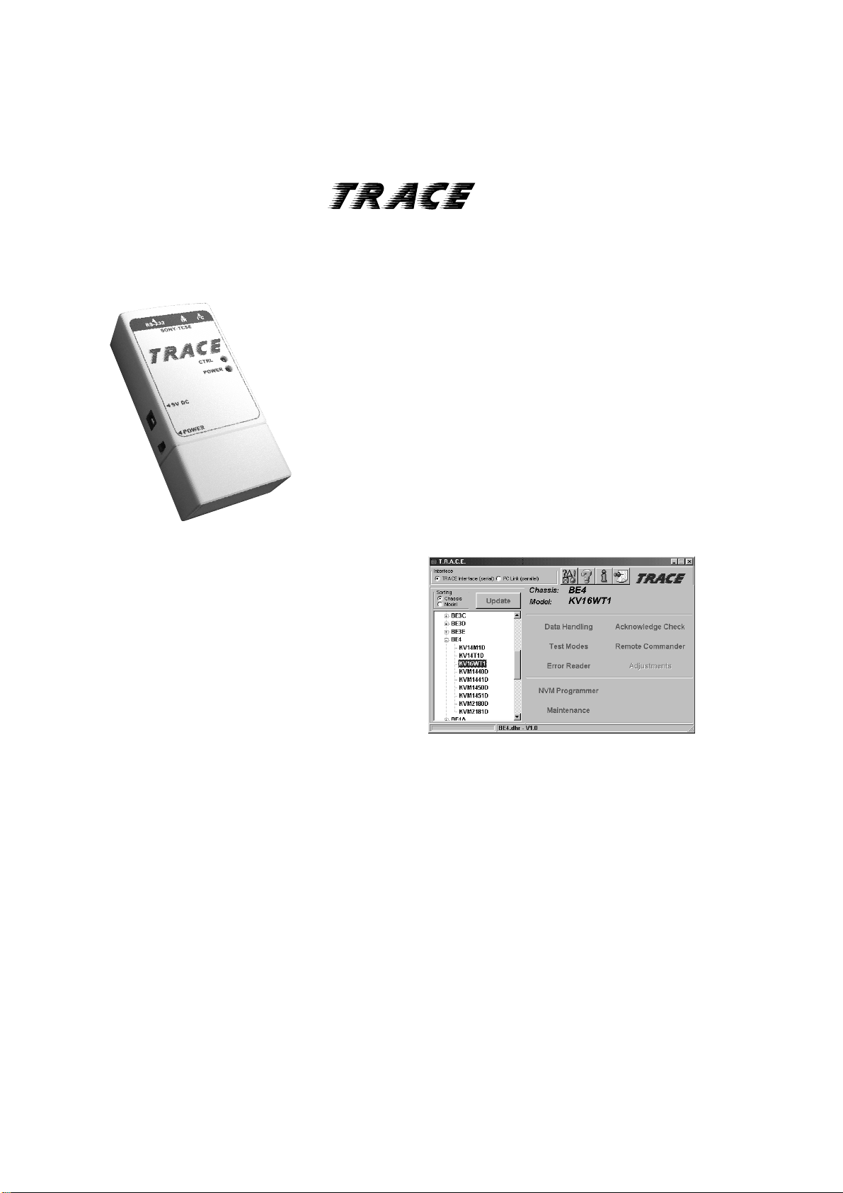
A newTV Repair Assistance Tool that combines ease of use and powerful PC software tools to
allow you to save valuable time during manyTV repairs.
The TRACE interface connects to the PC's serial port. It provides
connection to the TV's I2C bus and can be provided with an InfraRed
transmitter (optional).
The interface is powered by a standard 9V PP3 battery for portable
use, and can also be powered by an external 9V/25mA DC power
supply.
The TRACE software that is supplied with the interface allows you to:
•
Read, restore and compare NVM contents via the I2C bus
Acknowledge check of all I2C devices in the TV set
•
Read Error Codes (emulation of the Error Reader tool)
•
With the optional IRAdd-on kit, the following features can be added:
Remote Commander emulation
•
User programmable Functional Check through Infrared
•
Fast and documented Test Mode setting of all SonyTV chassis
•
Additional features such as Adjustments and Troubleshooting are
available in chassis-dependent software modules. Please contact your
local Sony Service organisation for the latest information.
Note: For workshops already using the existing I2C Link parallel port interface (9-948-320-30), this software can be used as well, replacing the
TV Data Handling software (9-948-340-50), but Error Reader and IR functions can only be accessed with the TRACE interface.
Partnumbers: TRACE Starter Kit (TRACE interface + software): 9-948-320-70
TRACE Software (for users of the I2C Link interface): 9-948-340-80
TRACE IRAdd-on (IR interface + Remote Commander software): 9-948-320-80
PC requirements: IBM-compatible PC with operating system Windows95, Windows98, or WindowsNT*.
* WindowsNT only supported withTRACE interface
Sony Corporation
Sony UK
9-927-408-01
Service Promotions Dept.
English
01FP7140-1
Printed in U.K.
© 2001.6
 Loading...