

Specifications
Power requirements
Power consumption (W)
Television system
Color system
Channel coverage
B/G
Audio output (speaker)
Inputs
Outputs
Picture tube
Tube size (cm)
Screen size (cm)
Dimensions (w/h/d, mm)
Mass (kg)
KV-2199M5T
110 – 240 V AC, 50/60 Hz
Indicated on the rear of the TV
B/G
PAL, PAL 60, SECAM, NTSC4.43, NTSC3.58 (AV IN)
VHF: E2 to E12/UHF: E21 to E69/CATV: S01 to S03, S1 to S41
3 W + 3 W
(antenna): 75 ohms external terminal
… (video input) jacks: phono jacks
(video): 1 Vp-p, 75 ohms
(audio): 500 mVrms, high impedance
(earphone jack): mini jack
Ú (monitor output) jacks: phono jacks
(video): 1 Vp-p, 75 ohms
(audio): 500 mVrms
21 in.
54
51
610 × 470 × 474
22
Design and specifications are subject to change without notice.
Note
Measured
diagonally
Measured
diagonally
Sony Corporation Tokyo, Japan
3-865-039-11 (1)
Trinitr on Color TV
Operating Instructions
Mode d’emploi
GB
FR
PR
AR
KV-2199M5T
1998 by Sony Corporation
2
3
1
2
SELECT
SELECT PROGR
1
PROGR
VHF LOW B/G
1
3
Getti g Started
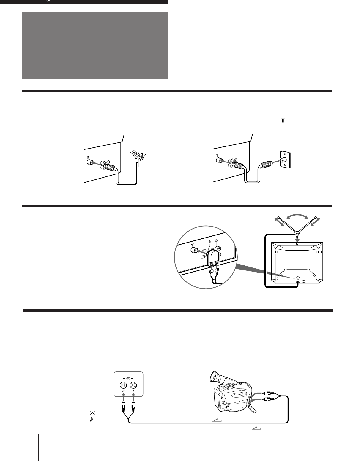
Connections
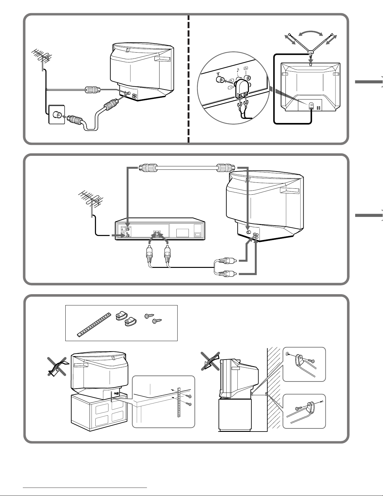
Connecting a VHF antenna or a combination VHF/UHF antenna
— 75-ohm coaxial cable (round)
Attach an optional IEC antenna connector to the 75-ohm coaxial cable. Plug the connector into the (antenna) socket
at the rear of the TV.
Rear of TV
or
Rear of TV
On a wall
Connecting an indoor antenna
3
2
1
Note
• You are advised to use an outdoor antenna for better reception.
Connecting optional equipment
You can connect optional audio/video equipment to your TV such as a VCR, multi disc player, camcorder, video
game or stereo system.
Connecting video equipment using the … (video input) jacks
Front of TV
Camcorder
to video and
audio outputs
to …
(video input)
(video) and
(audio) inputs
: Signal flow
-GB
4
Getting Started

Rear of TV
to antenna socket
to antenna
output
VCR
to …
(video input)
(video) and
(audio) inputs
When connecting video equipment to the
… (video input) jack
to video
and audio
outputs
: Signal flow
Do not connect video equipment to the … (video input) jacks at the front and the rear of your TV simultaneously; otherwise the picture
will not be displayed properly on the screen.
Connecting audio/video equipment using the Ú (monitor output) jack
Rear of TV
to antenna socket
to antenna
output
VCR
or
Audio system
GB
to Ú
(monitor output)
(video) and
(audio) outputs
to video
and audio
inputs
: Signal flow
When recording through the Ú (monitor output) jack
Do not change the channel or video input while recording with a VCR; otherwise the channel or video input you are recording also will be
changed.
Getting Started
-GB
5
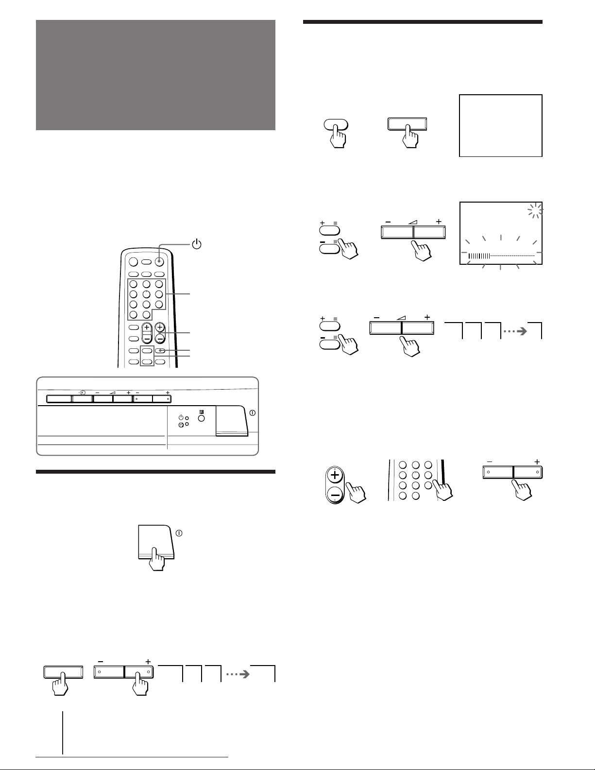
Presetting channels
AUTO PROGRAM
SELECT
SELECT
1 2 3 1
You can preset up to 100 TV channels in numerical
sequence from program position 1 using the buttons on
the remote commander or the TV.
You can preset TV channels quickly, automatically or
manually.
Remote commander
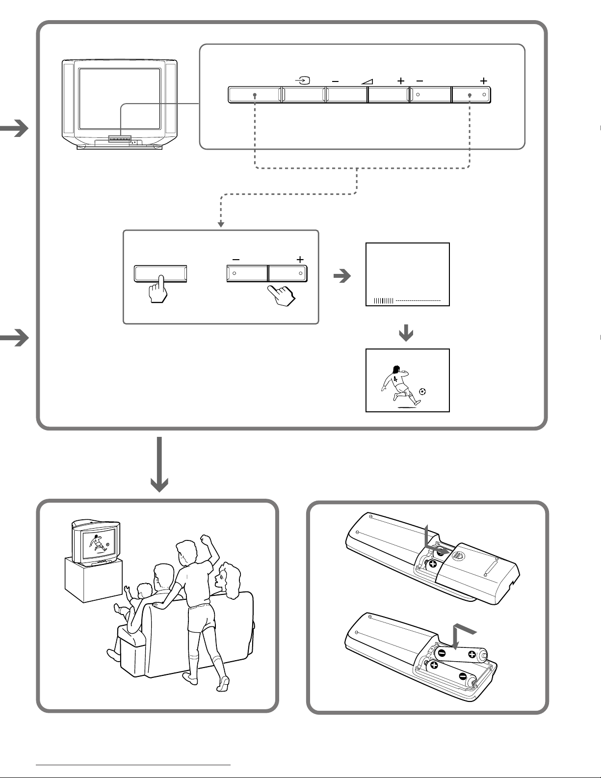
Presetting channels automatically
1 Press SELECT on the remote commander or
the TV until “AUTO PROGRAM” appears on
the screen.
or
2 Press +/– on the remote commander or
. +/– on the TV.
1
or
VHF LOW B/G
Front of TV
SELECT PROGR
Quick channel presetting
1 Press U to turn on the TV.
Number
PROGR +/–
SELECT
+/–
3 Press +/– on the remote commander or
. +/– on the TV again.
or
To start presetting channels automatically
from the specified program position
Press PROGR +/– or number buttons on the remote
commander or PROGR +/– on the TV until the
required program position appears on the screen after
step 2 of “Presetting channels automatically.”
PROGR
or
3
1
2
6
4
5
9
7
8
÷
0
or
PROGR
When the TV is turned on in standby mode, press
on the remote commander.
u
2 Press SELECT and PROGR + on the TV
simultaneously for one to two seconds.
SELECT PROGR
-GB
6
Getting Started
1 2 3 1

Presetting channels manually
Disabling program positions
1 Press SELECT on the remote commander or
the TV until “MANUAL PROGRAM” appears
on the screen.
SELECT
or
SELECT
MANUAL PROGRAM
2 Press +/– on the remote commander or
. +/– on the TV.
or
3 Press PROGR +/– or number buttons on the
remote commander or PROGR +/– on the TV
until the required program position
appears on the screen.
PROGR
or
3
1
2
6
4
5
9
7
8
÷
0
or
PROGR
1 Press PROGR +/– or number buttons on the
remote commander or PROGR +/– on the TV
until the unused or unwanted program
position appears on the screen.
2 Press SELECT on the remote commander or
the TV until “MANUAL PROGRAM” appears
on the screen.
3 Press +/– on the remote commander or
. +/– on the TV.
4 Press PIC MODE on the remote commander.
5 Press SELECT on the remote commander or
the TV.
To preset the disabled program position again
Preset the channel quickly, automatically or manually
.
4 Press +/– on the remote commander or
. +/– on the TV until the required channel
picture appears on the screen.
or
VHF LOW B/G
5 Press SELECT on the remote commander or
the TV.
SELECT
or
SELECT
1
Getting Started
-GB
7

O eratio s
VIDEO
1
;
Watching the TV
1 Press U to turn on the TV.
When the TV is turned on in standby mode, press
on the remote commander.
u
2 Select the TV program you want to watch.
To select a program position directly
Press the number button.
1
3
2
Turning off the TV
To turn off the TV temporarily
Press u on the remote commander. The u indicator
on the TV lights up.
To turn off the TV completely
Press U on the TV.
If the power on the TV is turned off in standby mode, the
indicator on the TV may remain alight for a while.
u
Watching the video input
Press … .
4
7
÷
To select a two-digit program position, press
“-/--” before the number buttons.
For example: to select program position 25, press
“-/--,” and then “2” and “5.”
6
5
9
8
0
2 5
To scan through program positions
Press PROGR +/– until the program position you
want appears.
PROGR
3 Press . +/– to adjust the volume.
.
To watch TV
Press ;.
Muting the sound
Press ¤.
¤
8
-GB
Operations
MUTING

Displaying on-screen information
0
Press .
The program position, local system, and TV settings are
displayed on the screen.
• If no buttons or controls are pressed for more than two hours
after the TV is turned on using the Wake Up Timer, the TV
automatically turns into standby mode. If you want to
continue watching the TV, press any button or control on the
TV or remote commander.
Setting the Sleep Timer
You can set the TV automatically turned off as you
program.
1
AUTO B/G
DYNAMIC
Setting the Wake Up Timer
You can set the TV automatically turned on as you
program.
1 Press © repeatedly to set the timer.
The on-screen display appears and the indicator
on the TV lights up.
WAKE UP TIMER:10M
After 10 minutes
Press .
SLEEP TIMER:30M SLEEP TIMER:60M
After 30 minutes
SLEEP TIMER:OFF SLEEP TIMER:90M
No sleep timer
After 60 minutes
After 90 minutes
To cancel the Sleep Timer, press repeatedly until
“SLEEP TIMER: OFF” appears, or turn off the TV.
Changing the on-screen display
language
You can use buttons on the remote commander or the
TV to change the on-screen display language.
WAKE UP TIMER:OFF WAKE UP TIMER:12H00M
No wake up timer
After 12 hours
2 If you want a particular TV program or video
input to be displayed using the Wake Up Timer,
select the TV program or video input.
3 Press u on the remote commander or set
the Sleep Timer to turn off the TV in
standby mode.
To cancel the Wake Up Timer, press © repeatedly
until “WAKE UP TIMER: OFF” appears, or turn off the
main power of the TV.
Notes
• The Wake Up Timer starts immediately after the on-screen
display disappears.
• The last TV program position or video input just before the TV
turns into standby mode will appear when the TV is turned on
using the Wake Up Timer.
+/–
SELECT
1 Press SELECT until the screen appears as
follows:
SELECT
LANGUAGE /
: ENGLISH
2 Press +/– to select “ ”.
: LANGUAGE /
Note
• You can also use SELECT and . +/– on the TV to select the
on-screen display language.
Operations
9
-GB
-GB

÷
0
Adjusting the
picture
Note on the SOUND MODE button
• The sound mode feature is unavailable for your TV. Thus, the
SOUND MODE button on the remote commander is not used
for your TV.
SOUND
MODE
+/–
SELECT
PIC MODE
Each time you press SELECT, the screen changes as
follows:
(Operative for
NTSC signal
only)
2 Press +/– to adjust the item.
3 To adjust other items, repeat steps 1 and 2.
Selecting the picture mode
Press PIC MODE until the mode you want
appears.
PIC MODE
Each time you press PIC MODE, the screen changes as
follows:
High contrast
picture
DYNAMIC STANDARDSOFT
Note
• If you change the picture mode after the following
adjustments, the adjustment changes in accordance with the
picture mode.
Soft picture
(good for video
games)
Normal
picture
Note
• You can also use SELECT and . +/– on the TV to adjust the
picture setting.
Front of TV
SELECT PROGR
If the picture color is abnormal when receiving
programs through the (antenna) terminal
Change the “COLOR SYSTEM” setting or adjust the
“COLOR” level in the on-screen display until the color
becomes normal.
If the picture is abnormal when receiving
programs through the … (video input) jack
Change the “COLOR SYSTEM” setting or adjust the
“COLOR” level in the on-screen display until the color
becomes normal.
Note
• Normally set “COLOR SYSTEM” to “AUTO.”
Adjusting the picture setting
1 Press SELECT until the item you want to
adjust appears.
SELECT
-GB
Operations
10

Viewing Teletext
…
;
Number
Holding a Teletext page
Press … .
The symbol “j” appears at the top left corner of the
screen.
To resume normal Teletext operation, press …
again or .
Using FASTEXT
This feature allows you to quickly access a Teletext
page that uses FASTEXT. When a FASTEXT program is
broadcasted, the colored menus appear at the bottom of
the screen. The colors of the menus correspond to the
red (+), green (SELECT), yellow (–), and blue (PIC
MODE) color-coded buttons on the remote
commander.
A/B
©
PROGR +/–
FASTEXT
Displaying Teletext
1 Select a TV channel which carries the
Teletext broadcast you want to watch.
2 Press to display the Teletext.
A Teletext page (normally the index page) appears
on the screen. If there is no Teletext broadcast, 100
appears at the top left corner of the screen.
To turn off Teletext, press ;.
Checking the contents of a Teletext service
Press © to display an overview of the Teletext
contents and page numbers.
Selecting a Teletext page
Press the number buttons to enter the three-digit page
number of the Teletext page you want.
If you make a mistake, enter the correct page number
again.
To access the next or previous page, press PROGR +/–.
You can also access a Teletext page of any page
numbers that appear in the colored column at the
bottom of the screen using the corresponding colorcoded button on the remote commander.
To access a FASTEXT menu, press the color-coded
button on the remote commander that corresponds to
the colored menu which appears at the bottom of the
screen. The menu page appears on the screen after
several seconds.
Revealing concealed information
Press .
To conceal the information, press again.
Enlarging the Teletext display
Press A/B .
Each time you press A/B , the Teletext display
changes as follows:
Enlarge
zzz
upper half
Superimposing a Teletext page on the TV
picture
Press .
Each time you press , the screen changes as follows:
z Teletext z Teletext and TV z TV
Waiting for a Teletext page while watching a
TV program
Enlarge
lower half
Normal size
1 Enter the page number of the Teletext you want to
refer, then press .
2 When the page number appears on the screen,
press to turn on the Teletext.
Operations
11
-GB

Troubleshooting
If you have any problems, read this manual again and
check the countermeasure for each of the symptoms
listed below.
If the problem persists after trying the methods below,
contact your nearest authorized service center or dealer.
Snowy picture
Noisy sound
/ Check the antenna.
/ Check the antenna connection on the TV
and on the wall.
No picture
No sound
/ Press U or u.
/ Check the antenna connection.
/ Check the VCR connections.
/ Check the power cord connection.
/ Check the standby mode.
Good picture
No sound
/ Press . +.
/ Press ¤.
No color
Dotted lines or stripes
/ This may be caused by local interference
(e.g. cars, neon signs and hair dryers).
Adjust the antenna for minimum interference.
Double images or “ghosts”
/ This may be caused by reflections from
nearby mountains or buildings. A highly
directional antenna may improve the
picture.
/ Adjust the COLOR level in the on-screen
display.
/ Check the COLOR SYSTEM setting.
TV cabinet creaks
/ Even if the picture or the sound is normal,
changes in the room temperature
sometimes make the TV cabinet expand or
contract, making a noise. This does not
indicate a malfunction.
Note on the remote commander
• The supplied remote commander is used on several models of
the TV. If you do not find instructions for some controls that
are on the remote commander, that means your TV does not
employ the features of those controls, e.g.
MODE.
Notes
• When you turn on the TV, you may hear the “boon” sound
that is caused by the demagnetization of the TV. This does not
indicate a malfunction.
• The picture color may become abnormal if you change the
direction of your TV. To obtain the normal picture color, press
on the TV to turn off the TV for five minutes and then turn
U
it on again.
• Design and specifications are subject to change without notice.
• All contents in the instruction manual are subject to change
without notice.
and SOUND
12
-GB
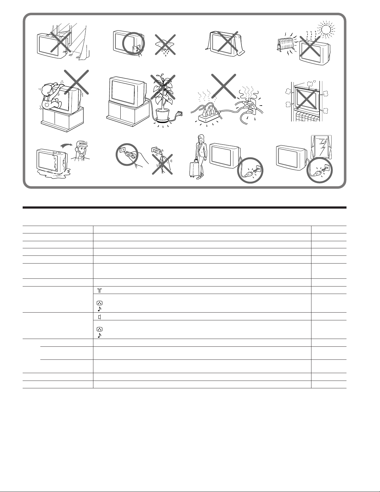
WARNING
Do not install the appliance in a confined space, such as
a bookcase or built-in cabinet.
Additional Information

Raccordement
Raccordez une antenne VHF ou une antenne combinée VHF/UHF
— câble coaxial de 75 ohms (rond)
Branchez un connecteur d’antenne IEC optionnel au câble coaxial de 75 ohms. Introduisez le connecteur dans la prise
˘ (d’antenne) à l’arrière du téléviseur.
Arrière du téléviseur Arrière du téléviseur
Sur une prise
d’antenne murale
ou
Raccordement d’une antenne interieure
3
2
1
Remarque
• Pour une qualité de réception optimale, nous vous conseillons d'utiliser une antenne extérieure.
Raccordement d’autres appareils
Vous pouvez raccorder un appareil audio/vidéo optionnel comme un magnétoscope, un lecteur multidisque, un
caméscope, une console de jeux vidéo ou chaîne stéréo.
Raccordement d’un équipement vidéo au moyen de la prise … (entrée vidéo)
Avant du téléviseur
Caméscope
vers les sorties
audio et vidéo
vers
… (entrée vidéo)
entrées (vidéo) et
(audio)
: Sens du signal
-FR
4
Préparation

Arrière du téléviseur
vers la prise d’antenne
vers la sortie
d’antenne
Magnétoscope
vers
… (entrée vidéo)
entrées (vidéo) et
(audio)
vers les
sorties audio
et vidéo
: Sens du signal
Lors du raccordement d’un équipement vidéo à la prise … (entrée vidéo)
Ne raccordez pas simultanément un équipement vidéo aux prises … (entrée vidéo) situées à l’avant et à l’arrière de votre téléviseur, sinon
l’image ne sera pas affichée correctement à l’écran.
Raccordement de l’équipement audio/vidéo au moyen de la prise Ú (sortie moniteur)
Arrière du téléviseur
vers la prise d’antenne
vers la
sortie
d’antenne
Magnétoscope
ou
Chaîne stéréo
FR
vers
Ú(sortie moniteur)
sorties (vidéo) et
(audio)
vers les
entrées audio
et vidéo
: Sens du signal
Lors du raccordement par le biais de la prise Ú (sortie moniteur)
Ne changez pas la chaîne ou l’entrée vidéo pendant que vous effectuez un enregistrement avec un magnétoscope, car la chaîne ou l’entrée
vidéo que vous êtes en train d’enregistrer changera également.
Préparation
5
-FR

Présélection des
AUTO PROGRAM
SELECT
SELECT
1 2 3 1
Préselection automatique des chaînes
chaînes
Vous pouvez présélectionner jusqu’à 100 chaînes de
télévision dans l’ordre numérique à partir de la
position de programmation 1 à l’aide des touches de la
télécommande ou du téléviseur.
Vous pouvez présélectionner des chaînes télévisées
suivant une procédure rapide, automatique ou manuelle.
Télécommande
Numéro
PROGR +/–
SELECT
+/–
Avant du téléviseur
1 Appuyez sur la touche SELECT de la
télécommande ou du téléviseur jusqu’à ce
que l’indication “AUTO PROGRAM” apparaisse
sur l'écran
.
ou
2 Appuyez sur la touche +/– de la
télécommande ou . +/– du téléviseur.
ou
VHF LOW B/G
3
Appuyez de nouveau sur +/– de la
télécommande ou
ou
.
+/– du téléviseur.
1
SELECT PROGR
Présélection rapide des chaînes de
télévision
1 Appuyez sur la touche U pour mettre le
téléviseur sous tension.
Lorsque le téléviseur est mis sous tension en mode de
veille, appuyez sur la touche u de la télécommande.
2 Appuyez simultanément sur les touches
SELECT et PROGR + du téléviseur pendant
une ou deux secondes.
SELECT PROGR
1 2 3 1
Pour lancer la présélection automatique des
chaînes à partir de la position de
programmation spécifiée.
Appuyez sur la touche PROGR +/– ou sur les touches
numériques de la télécommande ou sur la touche
PROGR +/– du téléviseur jusqu’à ce que la position de
programmation voulue apparaisse sur l’écran après
l’étape 2 “Préselection automatique des chaînes.”
PROGR
ou
3
1
2
6
4
5
9
7
8
÷
0
ou
PROGR
-FR
6
Préparation

Préselection manuelle des chaînes
1 Appuyez sur la touche SELECT de la
télécommande ou du téléviseur jusqu’à ce
que l’indication “MANUAL PROGRAM”
apparaisse
SELECT
sur l'écran
SELECT
ou
.
Désactivation de positions de
programmation
1 Appuyez sur la touche PROGR +/– ou sur les
touches numériques de la télécommande
ou sur la touche PROGR +/– du téléviseur
jusqu’à ce que la position de programmation
inutilisée ou indésirable apparaisse sur
l’écran.
MANUAL PROGRAM
2 Appuyez sur la touche +/– de la
télécommande ou . +/– du téléviseur.
ou
3 Appuyez sur la touche PROGR +/– ou sur les
touches numériques de la télécommande
ou sur la touche PROGR +/– du téléviseur
jusqu’à ce que la position de programmation
voulue apparaisse sur l’écran.
PROGR
ou
3
1
2
6
4
5
9
7
8
÷
0
ou
PROGR
4 Appuyez sur la touche +/– de la
télécommande ou . +/– du téléviseur
jusqu’à ce que l’image de la chaîne voulue
apparaisse sur l’écran.
2 Appuyez sur la touche SELECT de la
télécommande ou du téléviseur jusqu’à ce
que l’indication “MANUAL PROGRAM”
apparaisse
sur l'écran
.
3 Appuyez sur la touche +/– de la
télécommande ou . +/– du téléviseur.
4 Appuyez sur la touche PIC MODE de la
télécommande.
5 Appuyez sur la touche SELECT de la
télécommande ou du téléviseur.
Pour présélectionner à nouveau une position
de programmation désactivée
Présélectionnez la chaîne suivant la procédure rapide,
automatique ou manuelle.
ou
VHF LOW B/G
5 Appuyez sur la touche SELECT de la
telécommande ou du téléviseur.
SELECT
ou
SELECT
1
Préparation
-FR
7

O ératio s
VIDEO
1
;
Regarder la
télévision
1 Appuyez sur la touche U pour mettre le
téléviseur sous tension.
Lorsque le téléviseur est sous tension en mode de
veille, appuyez sur la touche u de la
télécommande.
2 Sélectionnez la chaîne télévisée que vous
voulez regarder.
Pour sélectionner directement une position
de programmation
Appuyez sur la touche numérique.
Mise hors tension du téléviseur
Pour mettre le téléviseur temporairement hors
tension
Appuyez sur la touche u de la télécommande. Le
témoin u sur le téléviseur s’allume.
Pour mettre le téléviseur complètement hors
tension
Appuyez sur la touche U du téléviseur. Si le téléviseur
est mis hors tension alors qu’il est en mode de veille,
l’indicateur u du téléviseur peut rester allumé
pendant un certain temps.
Visionner des enregistrements vidéo
Appuyez sur … .
1
4
7
÷
Pour sélectionner une chaîne à deux chiffres,
appuyez sur “-/--” avant d’appuyer sur les touches
numériques.
Par exemple: pour sélectionner la chaîne 25,
appuyez sur “-/--,” et ensuite sur “2” et sur “5.”
3
2
6
5
9
8
0
2 5
Pour explorer les chaînes
Appuyez sur PROGR +/– jusqu’à ce que la chaîne
voulue apparaisse.
PROGR
Pour regarder la télévision
Appuyez sur ;.
Pour couper le son
Appuyez sur ¤.
¤
3 Appuyez sur . +/– pour régler le volume.
.
-FR
8
Opérations
MUTING

Affichage d’informations à l’écran
0
Appuyez sur .
La position de programmation, le système local et les
réglages du téléviseur sont affichés à l’écran.
1
AUTO B/G
DYNAMIC
Réglage du programmateur d’éveil
Vous pouvez programmer le téléviseur pour qu’il se
mette automatiquement sous tension.
1 Appuyez plusieurs fois de suite sur ©
pour régler le programmateur.
Le menu d’affichage apparaît à l’écran et
l’indicateur du téléviseur s’allume.
• Si aucune touche ni commande n’est actionnée pendant plus
de deux heures après que le téléviseur a été mis sous tension à
l’aide du programmateur d’éveil, le téléviseur passe
automatiquement en mode de veille. Si vous voulez continuer
à regarder la télévision, appuyez sur une touche ou une
commande du téléviseur ou de la télécommande.
Réglage du programmateur
d’extinction
Vous pouvez programmer le téléviseur pour qu’il se
mette automatiquement hors tension.
Appuyez sur .
SLEEP TIMER:30M SLEEP TIMER:60M
Après 30 minutes Après 60 minutes
SLEEP TIMER:OFF SLEEP TIMER:90M
Programmateur
d’extinction
désactivé
Pour désactiver le programmateur d’extinction,
appuyez plusieurs fois de suite sur la touche
jusqu’à ce que l’indication “SLEEP TIMER: OFF”
apparaisse, ou mettez le téléviseur hors tension.
Après 90 minutes
WAKE UP TIMER:10M
Après 10 minutes
WAKE UP TIMER:OFF WAKE UP TIMER:12H00M
Programmateur
d’éveil désactivé
Après 12 heures
2 Si vous souhaitez qu’une émission télévisée
ou une entrée vidéo soit affichée par le
programmateur d’éveil, sélectionnez
l’émission télévisée ou l’entrée vidéo
voulue.
3
Appuyez sur la touche u de la télécommande
ou réglez le programmateur d’extinction pour
mettre le téléviseur en mode de veille.
Pour annuler le programmateur d’éveil, appuyez
plusieurs fois de suite sur © jusqu’à ce que
“WAKE UP TIMER: OFF” apparaisse, ou appuyez sur
le commutateur principal du téléviseur.
Remarques
• Le programmateur d’éveil démarre immédiatement après que
le menu d’affichage a disparu de l’écran.
• La dernière position de programme télévisé ou entrée vidéo
choisie juste avant que le téléviseur passe en mode de veille
apparaît lorsque le téléviseur est mis sous tension à l’aide du
programmateur d’éveil.
Changer la langue d’affichage des
menus
Vous pouvez utiliser les touches de la télécommande
ou du téléviseur pour changer la langue d’affichage sur
écran.
+/–
SELECT
1 Appuyez sur SELECT jusqu’à ce que l’écran
affiche l’indication suivante :
SELECT
LANGUAGE /
2
Appuyez sur + ou – pour sélectionner
Remarque
• Vous pouvez également utiliser les touches SELECT et . +/–
du téléviseur pour sélectionner la langue d’affichage des
menus.
: ENGLISH
: LANGUAGE /
“ ”.
-FR
Opérations
-FR
9

Réglage de l’image
÷
0
Remarque sur la touche SOUND MODE
La fonction de mode sonore n’est pas disponible sur
votre téléviseur. La touche SOUND MODE de la
télécommande n’est donc pas opérationnelle avec votre
téléviseur.
SOUND
MODE
+/–
SELECT
PIC MODE
Chaque fois que vous appuyez sur SELECT, l’écran
change selon la séquence suivante:
(Uniquement pour
un signal NTSC)
2 Appuyez sur +/– pour régler le paramètre.
3 Pour régler d’autres paramètres, répétez les
étapes 1 et 2.
Sélection du mode d’image
Appuyez sur PIC MODE jusqu’à ce que le mode
voulu apparaisse.
PIC MODE
Chaque fois que vous appuyez sur PIC MODE, l’écran
change selon la séquence suivante:
Image peu contrastée
Image très
contrastée
DYNAMIC STANDARDSOFT
Remarque
• Si vous changez le mode d’image après avoir effectué les
réglages suivants, le réglage change en fonction du mode
d’image.
(idéale pour
les jeux vidéo)
Image
normale
Remarque
• Vous pouvez également utiliser les touches SELECT et . +/–
du téléviseur pour modifier les réglages de l’image.
Avant du téléviseur
SELECT PROGR
Si les couleurs de l’image sont anormales lors de
la réception d’émissions télévisées via la borne ˘
(antenne)
Changez le réglage de “COLOR SYSTEM”, ou réglez le
niveau “COLOR” dans l’écran de menu jusqu’à ce que
les couleurs deviennent normales.
Si la couleur de l’image est anormale lors de la
réception de programmes via les prises
…
(entrée vidéo)
Changez le réglage de “COLOR SYSTEM” ou réglez le
niveau “COLOR” dans l’écran de menu jusqu’à ce que
les couleurs deviennent normales.
Remarque
• En principe, réglez “COLOR SYSTEM” sur “AUTO.”
Modification des réglages de l’image
1 Appuyez sur SELECT jusqu’à ce que le
paramètre que vous voulez modifier
apparaisse.
SELECT
-FR
Opérations
10

Utilisation du
télétexte
…
;
Numéro
A/B
©
Affichage du Télétexte
1 Sélectionnez une chaîne télévisée qui
propose le service télétexte que vous
désirez regarder.
2 Appuyez sur pour afficher le télétexte.
Une page du télétexte (la page d’index en règle
générale) s’affiche. Si la chaîne ne propose pas de
service télétexte, 100 s’affiche dans le coin
supérieur gauche de l’écran.
Pour faire disparaître le télétexte, appuyez sur ;.
Visualisation du contenu du service télétexte
Appuyez sur © pour afficher un aperçu du
contenu de télétexte et des numéros de page.
Sélection d’une page de télétexte
Appuyez sur les touches numériques pour entrer le
numéro de page à trois chiffres correspondant à la page
de télétexte que vous désirez afficher.
Si vous commettez une erreur, entrez à nouveau le
numéro de page correct.
Pour accéder à la page suivante ou précédente,
appuyez sur PROGR +/–.
Vous pouvez également accéder aux pages de télétexte
affichées dans la colonne colorée au bas de l’écran à
l’aide des touches de couleur correspondantes de la
télécommande.
PROGR +/–
FASTEXT
Maintien d’une page de télétexte
Appuyez sur … .
Le symbole “j” apparaît dans le coin supérieur
gauche de l’écran.
Pour revenir au fonctionnement normal du télétexte,
appuyez de nouveau sur … ou .
Utilisation de FASTEXT
Cette caractéristique vous permet d’accéder
rapidement à une page de télétexte utilisant FASTEXT.
Lorsqu’un programme FASTEXT est diffusé, les menus
de couleur apparaissent au bas de l’écran. Les couleurs
des menus correspondent aux touches rouge (+), verte
(SELECT), jaune (–) et bleue (PIC MODE) de la
télécommande.
Pour accéder à un menu FASTEXT, appuyez sur la
touche colorée de la télécommande qui correspond au
menu coloré qui apparaît au bas de l’écran. La page de
menu apparaît sur l’écran après quelques secondes.
Apparition des informations cachées
Appuyez sur .
Pour cacher des informations, appuyez de nouveau sur
.
Doublement en hauteur du texte
Appuyez sur A/B .
Chaque fois que vous appuyez sur A/B , l’affichage
du télétexte change comme suit:
z Doubler la hauteur de la moitié supérieure
$
Doubler la hauteur de la moitié inférieure
$
Taille normale
Incrustation d’une page de télétexte sur
l’image télévisée
Appuyez sur .
Chaque fois que vous appuyez sur , l’écran change
comme suit:
z Télétexte z Télétexte et TV z TV
Attente d’une page télétexte pendant la
visualisation d’un programme télévisé
1 Entrez le numéro de page du télétexte que vous
désirez obtenir, puis appuyez sur .
2 Lorsque le numéro de page s’affiche à l’écran,
appuyez sur pour faire apparaître le télétexte.
Opérations
11
-FR

I formatio s com léme taires
Dépannage
Si vous rencontrez des problèmes, relisez ce mode
d’emploi et vérifiez les remèdes proposés pour chacun
des symptômes énumérés ci-dessous.
Si le problème persiste après que vous avez appliqué
les méthodes ci-dessous, consultez un centre de service
après-vente agréé ou votre revendeur.
Image neigeuse
Son parasité
Pas d’image
Pas de son
/ Appuyez sur U ou u.
/ Vérifiez le raccordement de l’antenne.
/ Vérifiez le raccordement du magnétoscope.
/ Vérifiez le raccordement du cordon
d’alimentation.
/ Vérifiez le mode de veille.
Bonne image
Pas de son
/ Appuyez sur . +.
/ Appuyez sur ¤.
/ Vérifiez l’antenne.
/ Vérifiez le raccordement de l’antenne sur
le téléviseur et au mur.
Lignes pointillées ou rayures
/ Elles peuvent être provoquées par des
interférences locales (par ex. voitures,
enseignes au néon, sèche-cheveux, etc.).
Réglez l’antenne de façon à réduire les
interférences au maximum.
Images doubles ou “fantômes”
/ Elles peuvent être provoquées par des
réflexions sur des montagnes ou des
buildings. Un réseau d’antennes fortement
concentré peut améliorer la qualité de l’image.
-FR
12
Informations complémentaires
Pas de couleurs
/ Réglez le niveau COLOR dans le menu
d’affichage.
/ Vérifiez le réglage de COLOR SYSTEM.
Le châssis du téléviseur grince
/ Même si l’image et le son sont normaux,
une modification de la température
ambiante peut entraîner la dilatation ou la
contraction du châssis du téléviseur, ce qui
provoque des grincements. Il ne s’agit pas
d’un dysfonctionnement.
Remarque sur la télécommande
• La télécommande fournie est utilisée avec plusieurs modèles
de ce téléviseur. Par conséquent, si vous ne trouvez pas les
instructions pour certaines commandes qui se trouvent sur la
télécommande, cela signifie que votre téléviseur n’est pas doté
des fonctions activées par ces commandes, par exemple
SOUND MODE.
Remarques
• Lorsque vous mettez le téléviseur sous tension, il se peut que
vous entendiez un “grondement”, qui est provoqué par la
démagnétisation du téléviseur. Cela n’indique cependant pas
un dysfonctionnement.
• Il se peut que les couleurs de l’image deviennent anormales
lorsque vous changez l’orientation de votre téléviseur. Pour
restaurer les couleurs normales de l’image, appuyez sur la
touche
tension pendant environ cinq minutes et remettez-le ensuite à
nouveau sous tension.
• La conception et les spécifications sont sujettes à modifications
sans préavis.
• Le contenu du mode d’emploi est sujt à modifications sans
préavis.
AVERTISSEMENT
du téléviseur de façon à mettre le téléviseur hors
U
et
N’installez pas l’appareil dans un espace exigu, comme
dans une bibliothèque ou renfermé dans un boîtier.
 Loading...