

Sony KV.20XBR, KV25XBR Service Manual
SON~
TRINITRON~ COLOR TV
KV.20XBR/25XBR
(CABLE COMPATIBLE TV)
OPERATING INSTRUCTIONS
Welcome to the advanced world of Sony TV. For the
best results and the utmost satisfaction from your new
set, please read this manual thoroughly and retain it for
future reference.
OWNER'S RECORD
The model and serial numbers are located at the rear.
Record these numbers in the spaces provided below. Refer
to them whenever you call upon your Sony dealer regarding
this product.
Model No. Serial No.
CONTENTS
Warn i ng ..... ............ ....... ..................... ....... ................... 2
Precauti ons..................................... ................ ....... ..... 3
Featu res........................... .............. ....................... ...... 3
Location of controls.................................................. 4
Set -u p .. ..................... ....... ............. .............. .................. 5
Speakers..... ....... ..................... ...... ....... .......... .......... 5
Remote Commander .............................................. 6
Operation ........... ........ ....... ............................. .............. 6
Viewing TV programs............................................. 6
Listening to multichannel TV sound (MTS)
broadcasts .............. ....... .................... ......... ..........7
Additional picture and sound adjustments ........ 8
Presettng channels ................................................... 9
Adding channels..................................................... 9
Erasing channels.................................................... 9
Applications with other optional equipment ..........10
Con necti ons...................................... ................ ...... ....11
Optional audio/video connecting cables ......,.....11
VCR connection......................................................12
Microcomputer connection ..................................14
Selecting the various audio and video sources......15
Enjoying FM simulcasted programming .................16
Antenna/cable connection ........................................17
Specificati ons.. ............... ............................... ....... ......18
Troubleshooting ..........................................back cover
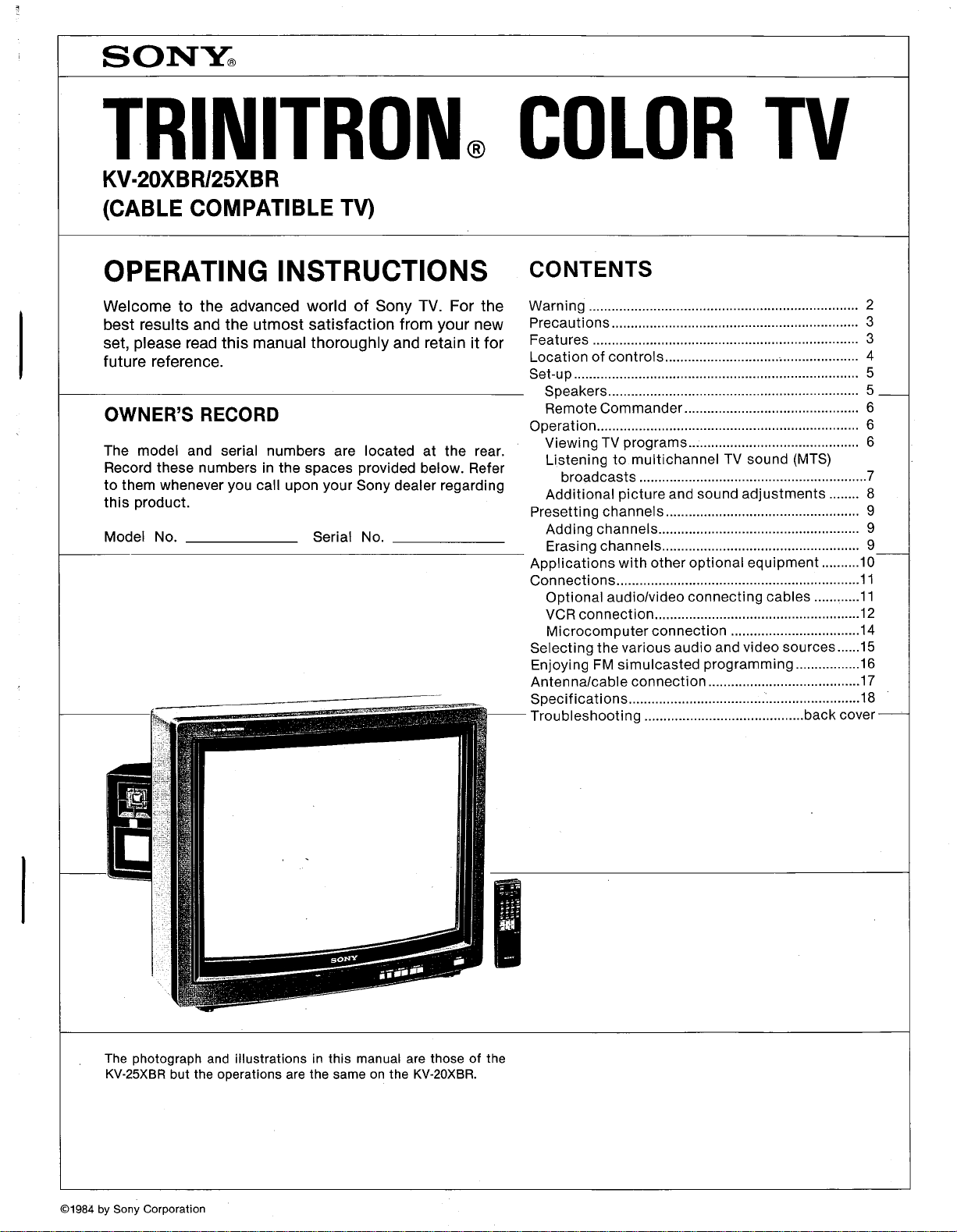
The photograph and illustrations in this manual are those of the
KV-25XBR but the operations are the same on the KV-20XBR.
(91984 by Sony Corporation
l!
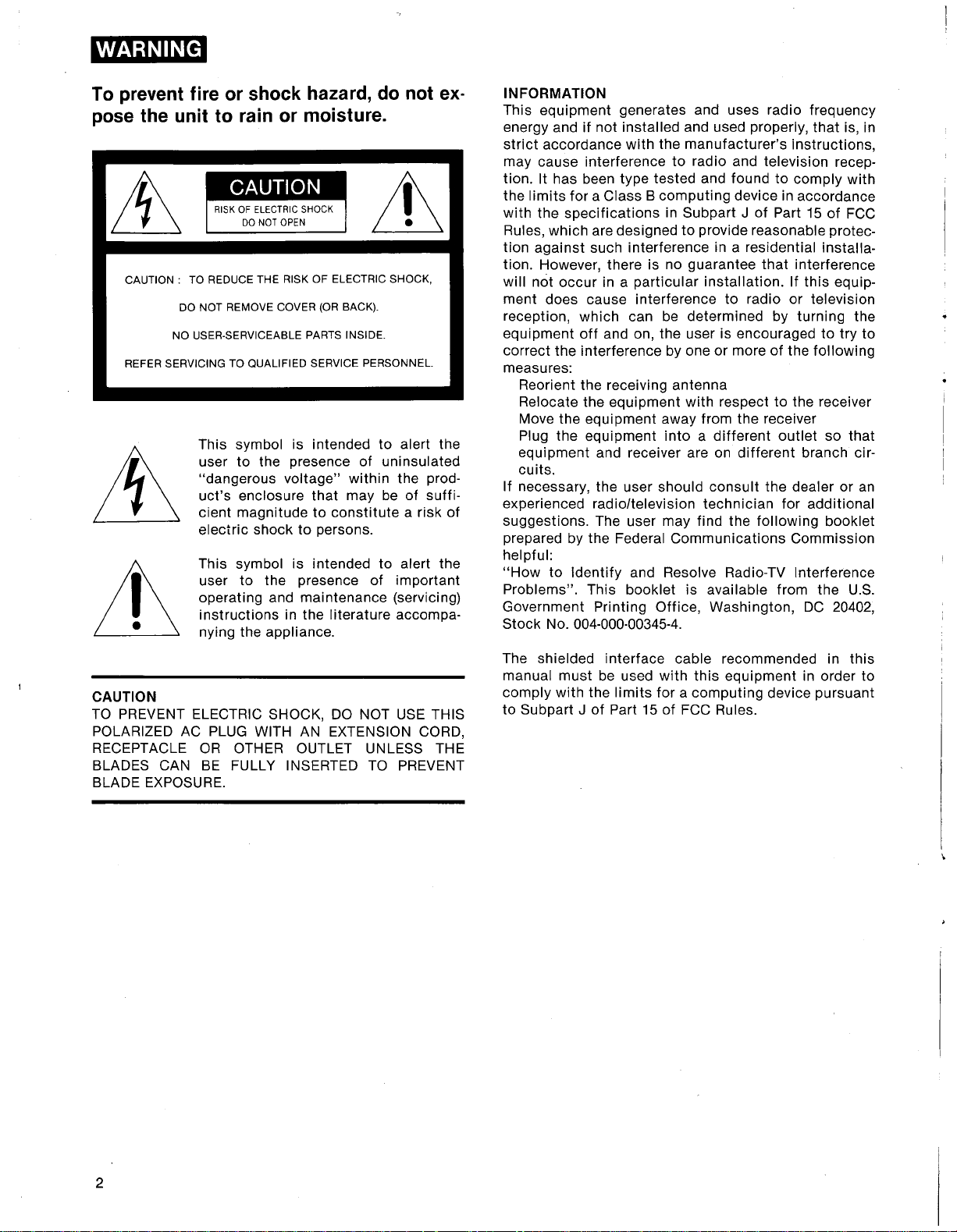
To prevent fire or shock hazard, do not ex.
pose the unit to rain or moisture.
&
CAUTION: TO REDUCE THE RISK OF ELECTRIC SHOCK,
DO NOT REMOVE COVER (OR BACK).
NO USER-SERVICEABLE PARTS INSIDE.
REFER SERVICING TO QUALIFIED SERVICE PERSONNEL.
This symbol is intended to alert the
user to the presence of uninsulated
"dangerous voltage" within the prod-
uct's enclosure that may be of suffi-
~
Lt
cient magnitude to constitute a risk of
electric shock to persons.
This symbol is intended to alert the
user to the presence of important
operating and maintenance (servicing)
instructions in the literature accompa-
nying the appliance.
~
INFORMATION
This equipment generates and uses radio frequency
energy and if not installed and used properly, that is, in
strict accordance with the manufacturer's instructions,
may cause interference to radio and television recep-
tion. It has been type tested and found to comply with
the limits for a Class B computing device in accordance
with the specifications in Subpart J of Part 15 of FCC
Rules, which are designed to provide reasonable protec-
tion against such interference in a residential installa-
tion. However, there is no guarantee that interference
will nòt occur in a particular installation. If this equip-
ment does cause interference to radio or television
reception, which can be determined by turning the
equipment off and on, the user is encouraged to try to
correct the interference by one or more of the following
measures:
Reorient the receiving antenna
Relocate the equipment with respect to the receiver
Move the equipment away from the receiver
Plug the equipment into a different outlet so that
equipment and receiver are on different branch cir-
cuits.
If necessary, the user should consult the dealer or an
experienced radio/television technician for additional
suggestions. The user may find the following booklet
prepared by the Federal Communications Commission
helpful:
"How to Identify and Resolve Radio-TV Interference
Problems". This booklet is available from the U.S.
Government Printing Office, Washington, DC 20402,
Stock No. 004-000-00345-4.
CAUTION
TO PREVENT ELECTRIC SHOCK, DO NOT USE THIS
POLARIZED AC PLUG WITH AN EXTENSION CORD,
RECEPTACLE OR OTHER OUTLET UNLESS THE
BLADES CAN BE FULLY INSERTED TO PREVENT
BLADE EXPOSURE.
The shielded interface cable recommended in this
manual must be used with this equipment in order to
comply with the limits for a computing device pursuant
to Subpart J of Part 15 of FCC Rules.
2
PRECAUTIONS
FEATURES
i Safety I
. Operate the set only on 120 V AC.
. One blade of the plug is wider than the other for the
purpose of safety and will fit into the power outlet only
one way. If you are unable to insert the plug fully into
the outlet, contact your dealer.
. Should any liquid or solid object fall into the cabinet,
unplug the set and have it checked by qualified person-
nel before operating it any further.
. Unplug the set from the wall outlet if it is not going to
be used for several days or more. To disconnect the
cord, pull it out by the plug. Never pull the cord itself.
¡instaiiation I
. To prevent internal heat build-up, do not block the
ventilation openings.
. Do not install the set in a hot or humid place or in a
place subject to excessive dust or mechanical vibration.
I Cleaning I
Clean the set with a slightly damp soft cloth. Use a mild
household detergent. Never use strong solvents such as
thinner or benzine as they might damage the finish of
the cabinet.
I Repacking I
Retain the original carton and packing materials for
safe transport of this set in the future.
Use of this television receiver for other than private
viewing of programs broadcast on UHF or VHF or
transmitted by cable companies for the use of the
general public may require authorization from the
broadcaster/cable company and/or program owner.
. New MicroblackTM TrinitronOO picture tube with more
finely pitched aperture grille for higher resolution,
higher contrast picture
. Buil.in stereo decoder decodes MTS (Multichannel
TV Sound) broadcasts into left and right stereo or SAP
(Second Audio Program) channels *
. Multi.band VHF/UHF/CATV tuner receives up to 125
cable channels for a total of 181 pOSSible off.air and
cable channels
. Supplied detachable speakers featuring Sony's APM
(Accurate Pistonic Motion) technology, magnetically
shielded to provide superb sound reproduction with no
interference to picture quality
. Two buil.in video and L1R audio line inputs and a new
AV uniconnector allow direct hook-up to VCRs, video
disc players, video games or other audiolvideo sources.
The AV uniconnector receives combined video and L1R
audio signals for one easy connection.
. Buil.in video and L1R audio line outputs provide the
selected output from the TV tuner or any of the equip.
ment connected to the audio-video line inputs or the AV
uniconnector.
. An A V (audio and video combined) type output jack
for continuous output from the TV tuner and easy con-
nection
. Buil-in RGB input for higher resolution display of
computer-generated text and color graphics
. Full-function RM-724 Remote Commander provides
wireless control of all operating controls
. On-screen displays for easy reference to operating
modes and adjustments
. Trinitone™ control allows you to adjust the color
temperature(tint) of the picture for the most pleasing
color
. New Dynamic Coior™ circuitry assures accurate,
life-like skintones and pure whites
. Dynamic Picture™ circuitry automatically adjusts
the picture contrast to produce more detail in bright and
dark areas of the scene
. Dynamic Focus™ circuitry automatically focuses the
scanning electron beam for enhanced sharpness over
the entire picture, especially in the corners
. Colorpure Filter™ separately processes 81W picture
information from color information to produce a
dramatically sharper picture
* Depends on availability of off-air stereo broadcasts.
3
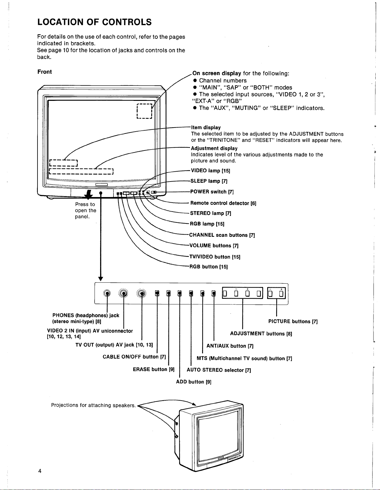
LOCATION OF CONTROLS
For details on the use of each control, refer to the pages
indicated in brackets.
See page 10 for the location of jacks and controls on the
back.
Front
r-- --,
L_____J
r--------- ---,
L_____________J
".---..
I
I i
i I
L___-,
On screen display for the following:
. Channel numbers
. "MAIN", "SAP" or "BOTH" modes
. The selected input sources, "VIDEO 1, 2 or 3",
"EXT-A" or "RGB"
. The "AUX", "MUTING" or "SLEEP" indicators.
Item display
The selected item to be adjusted by the ADJUSTMENT buttons
or the "TRINITONE" and "RESET" indicators will appear here.
Adjustment display
Indicates level of the various adjustments made to the
picture and sound.
VIDEO lamp 1151
SLEEP lamp 171
POWER switch 171
Remote control detector 161
STEREO lamp 171
RGB lamp 1151
CHANNEL scan buttons 171
VOLUME buttons 171
~..
PHONES (headphones) jack
(stereo mini.type) 181
VIDEO 2 IN (input) AV uniconnector
110,12,13,141
TV OUT (output) AV jack 110,131
CABLE ON/OFFbutton 171
Projections for attaching speakers.
(¡~
~
ERASE button 191
TVNIDEO button 1151
RGB button 1151
õ 0 0
PICTURE buttons 171
ADJUSTMENT buttons 181
ANT/AUX button 171
MTS (Multichannel TV sound) button 171
AUTO STEREO selector 171
ADD button 191
4
SET.U P
. i
I
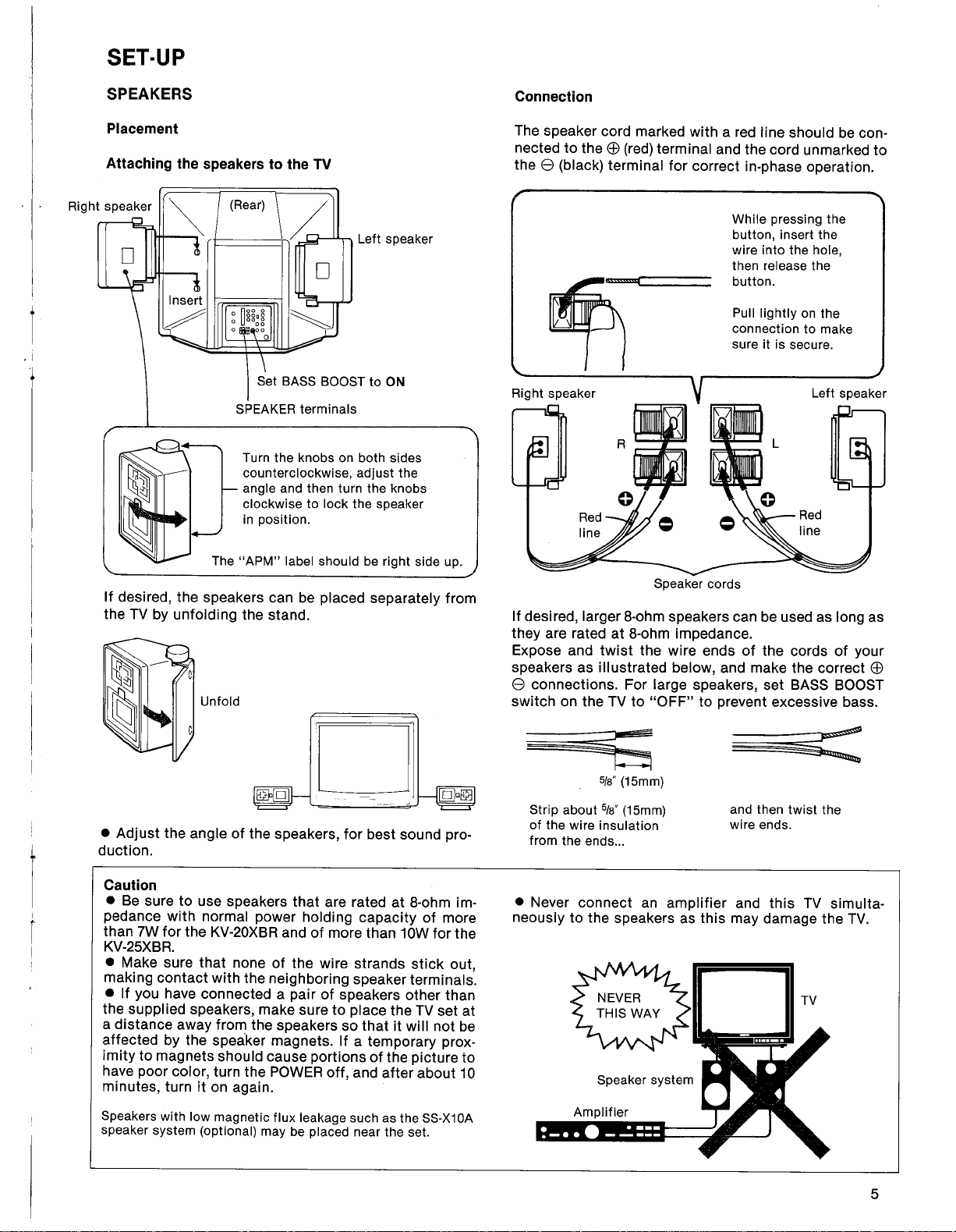
SPEAKERS
Placement
Attaching the speakers to the TV
Right speaker
SPEAKER terminals
Turn the knobs on both sides
counterclockwise, adjust the
angle and then turn the knobs
clockwise to lock the speaker
in position.
o
Left speaker
Connection
The speaker cord marked with a red line should be con-
nected to the EB (red) terminal and the cord unmarked to
the e (black) terminal for correct in-phase operation.
While pressing the
button, insert the
wire into the hole,
then release the
button.
Pull lightly on the
connection to make
sure it is secure.
~
Right speaker Left speaker
The "APM" label should be right side up.
If desired, the speakers can be placed separately from
the TV by unfolding the stand.
Unfold
If desired, larger 8-ohm speakers can be used as long as
they are rated at 8-ohm impedance.
Expose and twist the wire ends of the cords of your
speakers as illustrated below, and make the correct EB
e connections. For large speakers, set BASS BOOST
switch on the TV to "OFF" to prevent excessive bass.
~
CJ
Strip about 5/8" (15mm)
. Adjust the angle of the speakers, for best sound pro.
L
duction.
Caution
. Be sure to use speakers that are rated at 8-ohm im-
pedance with normal power holding capacity of more
than 7W for the KV-20XBR and of more than 10W for the
KV-25XBR.
. Make sure that none of the wire strands stick out,
making contact with the neighboring speaker terminals.
. If you have connected a pair of speakers other than
the supplied speakers, make sure to place the TV set at
a distance away from the speakers so that it will not be
affected by the speaker magnets. If a temporary prox-
imity to magnets should cause portions of the picture to
have poor color, turn the POWER off, and after about 10
minutes, turn it on again.
Speakers with low magnetic flux leakage such as the SS-X10A
speaker system (optional) may be placed near the set.
of the wire insulation
from the ends...
. Never connect an amplifier and this TV simulta-
neously to the speakers as this may damage the TV.
5/8" (15mm)
Speaker system
Amplifier
Speaker cords
~
and then twist the
wire ends.
TV
5
OPERATION
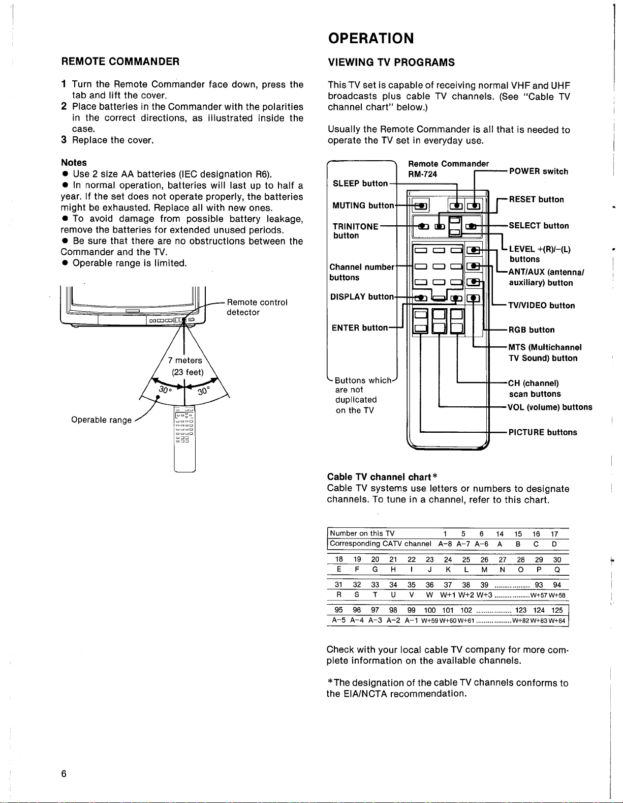
REMOTE COMMANDER
1 Turn the Remote Commander face down, press the
tab and lift the cover.
2 Place batteries in the Commander with the polarities
in the correct directions, as illustrated inside the
case.
3 Replace the cover.
Notes
. Use 2 size AA batteries (IEC designation R6).
. In normal operation, batteries will last up to half a
year. If the set does not operate properly, the batteries
might be exhausted. Replace all with new ones.
. To avoid damage from possible battery leakage,
remove the batteries for extended unused periods.
. Be sure that there are no obstructions between the
Commander and the TV.
. Operable range is limited.
Remote control
detector
VIEWING TV PROGRAMS
ThisTV set is capable of receiving normal VHF and UHF
broadcasts plus cable TV channels. (See "Cable TV
channel chart" below.)
Usually the Remote Commander is all that is needed to
operate the TV set in everyday use.
Remote Commander
RM.724
SLEEP button
MUTING button
TRINITONE
button
Channel number
buttons
DISPLAY button
ENTER button
POWER switch
RESET button
SELECT button
LEVEL +(R)/-(L)
buttons
ANT/AUX (antennal
auxilary) button
TVIVIDEO button
RGB button
MTS (Multichannel
TV Sound) button
~:J::
~::::
Buttons which
are not
duplicated
on the TV
CH (channel)
scan buttons
VOL (volume) buttons
PICTURE buttons
Cable TV channel chart *
Cable TV systems use letters or numbers to designate
channels. To tune in a channel, refer to this chart.
Number on this TV
Corresponding CATV channel
18 19
E F
31 32
R S T
20 21 22 23
G H I
33 34 35
U V
95 96 97 98 99 100 101 102 ......... ......... 123 124 125
A-5 A-4 A-3 A-2 A-1 W+59 W+60 W+61 ......... ......... W+82 W+83 W+84
Check with your local cable TV company for more com-
1 5
A-8 A-7 A-6
24 25 26
J K L M N
36 37 38 39 .................. 93 94
W W+1 W+2 W+3 ......... ......... W+57 W+58
6 14 15 16 17
B
A
27
C
28 29
0
p
D
30
Q
plete information on the available channels.
..
*The designation of the cable TV channels conforms to
the EIA/NCTA recommendation.
6
 Loading...