

Page 1
SONY.
TRINITRON. COLOR TV
OPERATING INSTRUCTIONS owner s record
4-482-387-41 (1)
Before operating the unit, piease read this manual thoroughly
and retain it for future reference.
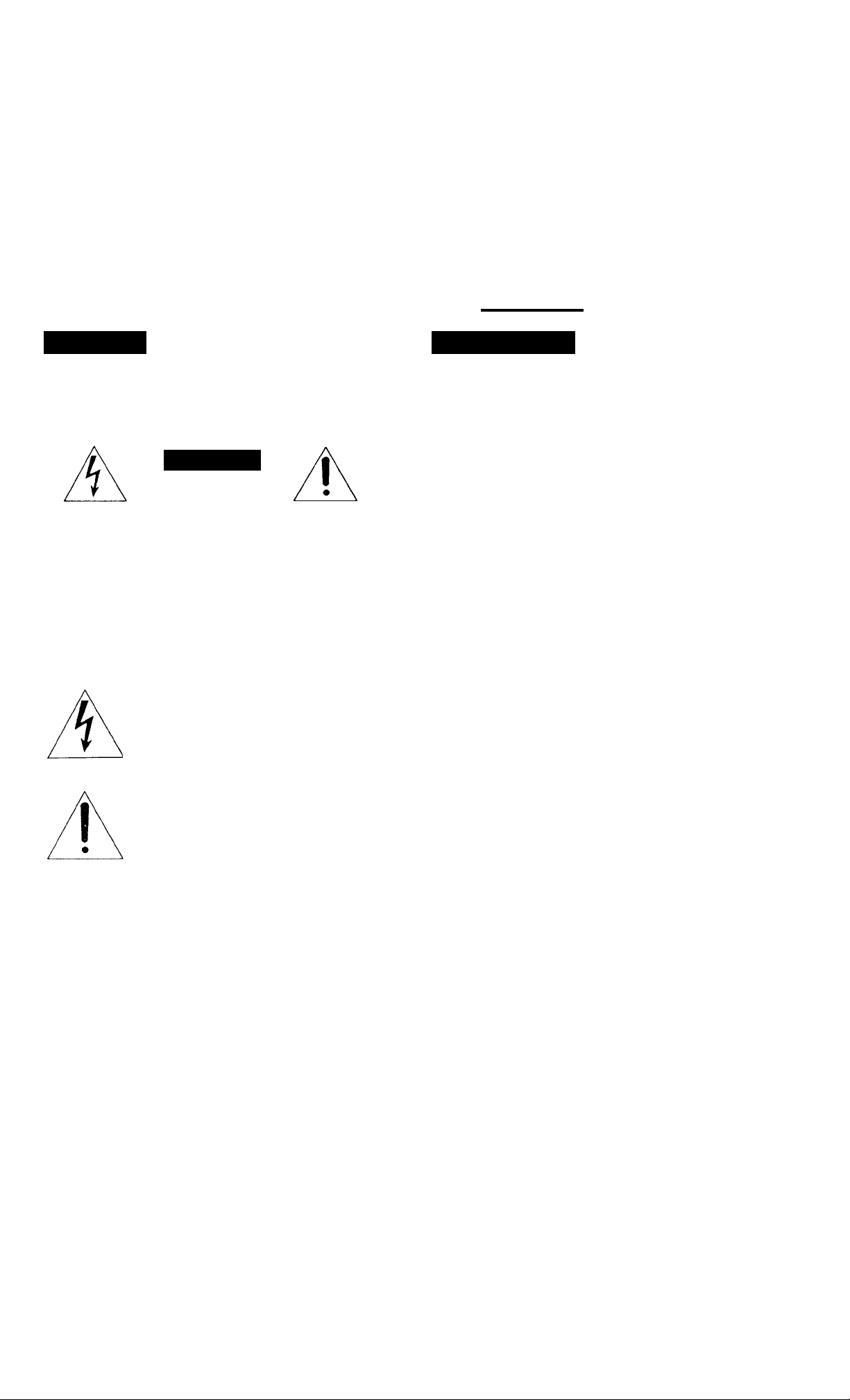
WARNING
To prevent fire or shock hazard, do not
expose the unit to rain or moisture.
CAUTION
RISK OF ELECTRIC SHOCK
00 NOT OPEN
CAUTION : TO REDUCE THE RISK OF ELECTRIC SHOCK,
DO NOT REMOVE COVER (OR BACK).
NO USER-SERVICEABLE PARTS INSIDE.
REFER SERVICING TO QUALIFIED SERVICE PERSONNEL.
The model and serial numbers are located on the rear. Record
these numbers in the spaces provided below. Refer to them
whenever you call upon your Sony dealer regarding this
product.
Model No,
Kl//5Tg^û
Serial No._
PRECAUTIONS
Safety
Operate the unit only on 120 V AC.
One blade of the plug is wider than the other for the
purpose of safety and will fit into the power outlet only
one way. If you are unable to insert the plug fully into
the outlet, contact your dealer.
Should any liquid or solid object fail into the cabinet,
unplug the unit and have it checked by qualified
personnel before operating it any further.
Unplug the unit from the wall outlet if it is not going to
be used for several days or more. To disconnect the
cord, pull it out by the plug. Never pull the cord itself.
Installation
To prevent internal heat build-up, do not block the
ventilation openings.
Do not install the unit in a hot or humid place or in a
place subject to excessive dust or mechanical vibration.
This symbol is intended to alert the user
to the presence of uninsulated
“dangerous voltage” within the product’s
enclosure that may be of sufficient
magnitude to constitute a risk of electric
shock to persons.
This symbol is intended to alert the user
to the presence of important operating
and maintenance (servicing) instructions
in the literature accompanying the
appliance.
CAUTION
TO PREVENT ELECTRIC SHOCK, DO NOT USE THIS
POLARIZED AC PLUG WITH AN EXTENSION CORD,
RECEPTACLE OR OTHER OUTLET UNLESS THE BLADES
CAN BE FULLY INSERTED TO PREVENT BLADE
EXPOSURE.
©1987 by Sony Corporation
Cleaning
Clean the unit with a slightly damp soft cloth. Use a mild
household detergent. Never use strong solvents such as
thinner or benzine as they might damage the finish of the
cabinet.
Repacking
Retain the original carton and packing materials for safe
transport of this unit in the future.
Use of this television receiver for other than private viewing
of programs broadcast on UHF or VHF or transmitted by
cable companies for the use of the general public may
require authorization from the broadcaster/cable company
and/or program owner.
Page 2
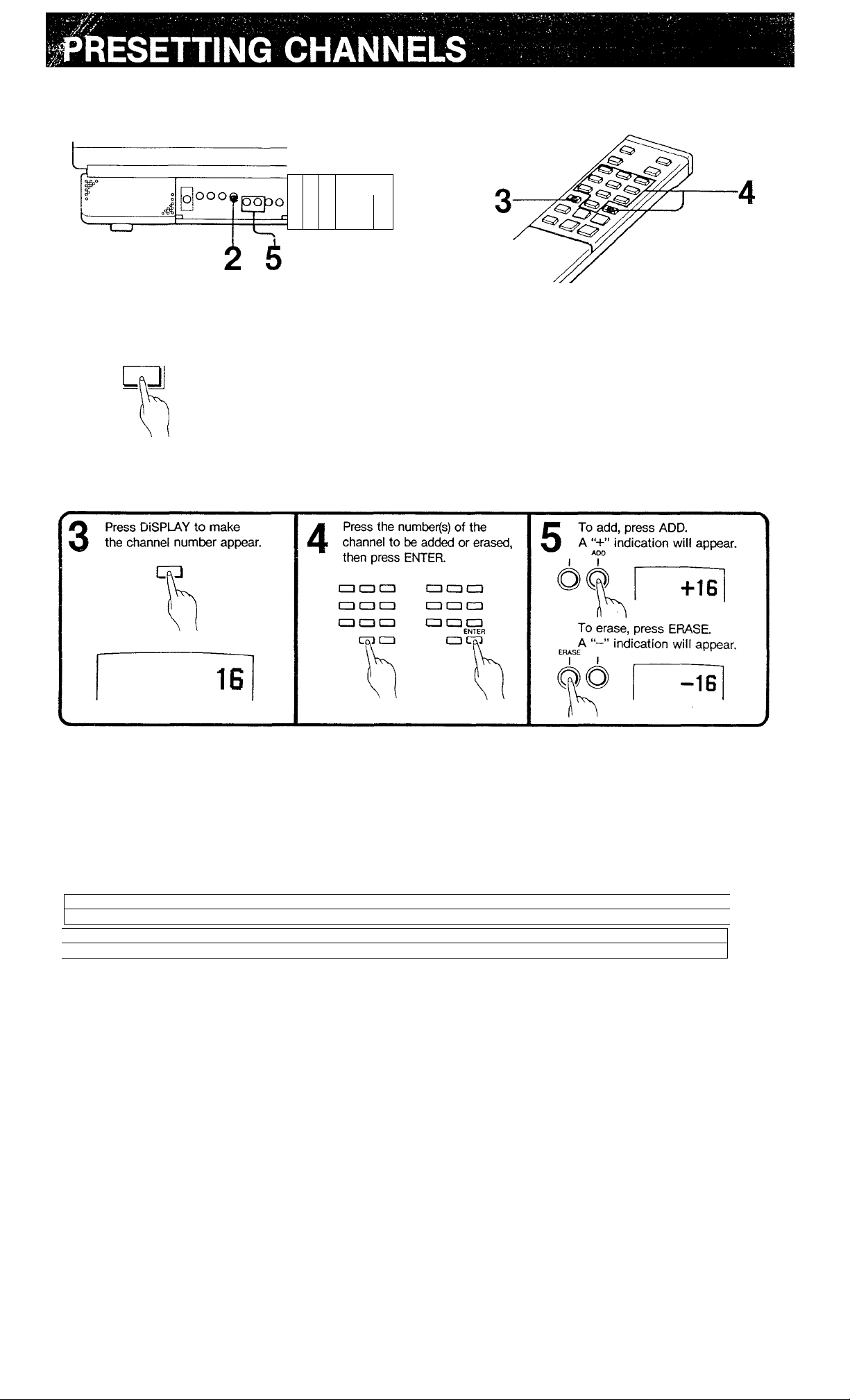
By adding and erasing channels, you can preset your TV
so that only the desired channels appear in sequence
when the CH “+” or is pressed.
□
o
o
ooo
"T
-----------
Receivable channels of your unit are:
VHP: 2-13 UHF: 14-69 CATV: 1-125
p
POWER
1
Press POWER
on the TV.
OFF ON
Repeat steps 4 and 5 for other channels to be added or
erased. To add erased channels again, repeat the steps in
adding.
Set the CABLE selector to:
ON for CATV channels
OFF for VHF/UHF channels
CABLE
Note
If you erase a VHF or UHF channel, the cable TV channel with
the same number will also be erased, and vice versa.
Cable TV systems use letters or numbers to designate
channels. To tune in a channel, refer to this chart.
Number on this TV
Corresponding CATV channel A-8 A-7 A-6 ABC
32 33
31
R S
*The designation of the cable TV channels conforms to the
EIA/NCTA recommendation.
T
35 36 37 38 39
34
V W W+1 W+2 W+3
U
1 5 6 14 15 16
...............
...........
........
93 94 95 96 97 98 99 100 101 102
.........
W+57W+58 A-5 A-4 A-3 A-2 A-1 W+59 W+60 W+61
Check with your local cable TV company for more
complete information on the available channels.
17 18 19 20 21
D E F G
Note
Pay cable TV systems use scrambled or encoded signals and
require special converters (decoders) in addition to the normal
cable connection.
22 23 24 25 26 27 28
H 1 J K L M N O P Q
........................
................
......... 123 124 125
.........
29
W+82 W+83 W+84
30
Page 3

I^GATION AND FUNCTION OF CONTROLS
Front
—
0
---------------
-----------------------------
4
^ L
—^ --------------------------- f=
—
FFl
LLiJ
--------------
---------------
0
RÏÏI
j
!
rn Bar display
Indicates level of volume and picture contrast.
[U Speaker
[3] Earphone jack (minijacl^
0 BRIGHT (brightness) control
Turn clockwise for more brightness or counterclockwise
for less.
fsl COLOR control
Turn clockwise for more color intensity or
counterclockwise for less.
0 HUE control
Turn clockwise to make the tones greenish or
counterclockwise to make them purplish.
0 CABLE selector
To view CATV programs, set this selector to ON.
0 ERASE button
Used for channel presetting. Press to erase channels.
0
ADD button
Used for channel presetting. Press to add channels.
0 POWER switch
Press to turn the unit on.
0 Remote control detector
Point the Remote Commander towards this detector.
0 SLEEP lamp
Lights up when the SLEEP button on the Remote
Commander is pressed.
0
On-screen display
Shows channel numbers, “MUTING”, and “SLEEP”
indications.
BATTERY INSERTION
■4
1 Open the lid.
Insert two size AA (R6)
batteries with correct
polarity.
-
0 PICTURE buttons
Press PICTURE “+” to increase picture contrast, or
to decrease it.
0 TVA/IDEO button
Press to view the picture from the connected VCR.
0 VOLUME buttons
Press VOL “+" to increase volume, or to decrease it.
0 CHANNEL scan buttons
Press “+” for higher-numbered channels and for
lower-numbered channels.
Notes
• In normal operation, batteries will last up to half a year. If
the unit does not operate properly, the batteries might be
exhausted. Replace all with new ones.
• To avoid damage from possible battery leakage, remove the
batteries for extended unused periods.
• Be sure that there are no obstructions between the
Commander and the TV.
• Operable range is limited.
• If a Remote Commander not recommended is used to
operate this TV, or if the supplied Remote Commander is
used to operate another TV, the TV may not operate
properly.
Page 4

Remote Commander RM-729
[T^ MUTING button
Press to mute the sound immediately.
The “MUTING” display will appear and remain on the
screen. Press it again or press VOLUME to restore
the sound.
[19]TVA^IDEO button**
DISPLAY button
Press to make the channel number appear on the
screen.
(21]PICTURE buttons**
[^VOLUME buttons* *
11^CH (channel) scan buttons* *
Press POWER on the TV.
1
Select the desired channel in one of the
following two ways.
O Press the number(s) of the channel. Then
0 To select channels already preset, press CFI
POWER
OFF ON
CABLE
press ENTER.
“+” for higher-numbered channels or for
lower numbered channels.
Set the CABLE selector to:
ON for CATV channels
OFF for VHF/UHF channels
m POWER switch
Once the unit is turned on with the POWER switch on
the TV, press to turn the unit off (standby mode). Press
again to turn it on.
SLEEP button
Press to have the unit turn off automatically after one
hour. The “SLEEP” display will appear on the screen a
few seconds and the SLEEP lamp on the TV will remain
lit for one hour.
To cancel the sleep timer, press again so that the
“SLEEP” display disappears, or turn off the TV.
[g§ Channel number buttons
Used to select channels.
[13 ENTER button
Used to select channels.
* *The functions of these buttons are duplicated on the TV.
^ Adjust VOLUME.
□
VOL
□
Adjust picture contrast.
a -r to increase
PICTURE
CD - to decrease
+ to increase
- to decrease
Page 5

ANTEN N A/CABLE CONNECTION
!lND0OR|g®||NA;;ADJ^
For VHF/UHF reception, use the supplied telescopic dipole
antenna.
to a wall outlet
If you cannot obtain satisfactory reception with the dipole
antenna, use an outdoor antenna.
Cable TV reception is only possible by connecting a cable
supplied by your local cable operator.
Adjust the length, direction and angle of both elements
symmetrically until the picture is clear.
1 Remove the indoor antenna from the antenna terminal
of the TV.
2 Prepare the antenna or cable end using the appropriate
connector, and connect the antenna or cable to the
antenna terminal of the TV. (See □ or 13 below.)
1 Check the cable type and attach the appropriate
connector to the antenna end.
2 Plug the connector into the VHF/UHF antenna terminal
on the rear of the unit.
*Most combination antennas are equipped with a signal
splitter. Take off the splitter and attach the proper connector.
Prepare the VHF antenna end using the appropriate
connector as illustrated in a
Attach an optional EAC66 U/V mixer to the TV antenna
terminal, and connect the cables to the U/V mixer.
Rear of TV
Note
When viewing CATV, connect the cable directly to the terminal.
If you use the U/V mixer, snow and noise may appear in the
pictures of the channels over 37 (W + 1).
Note to CATV system installer in the U.SVt.
This reminder is provided to call the CATV system installer’s
attention to Article 820-22 of the NEC that provides guidelines
for proper grounding and, in particular, specifies that the cable
ground shall be connected to the grounding system of the
building, as close to the point of cable entry as practical.
Page 6

VCR CONNECTION
With this connection, you don’t have to select channel 3 or
4 to view VCR playback.
Preparations
---------------------------------------------------------------
1 Turn on the TV.
2 Press the TV/VIDEO button so that the “VIDEO”
indication appears on the screen.
For operation, refer to the instruction manual furnished
with the VCR.
Television system
Channel coverage
American TV standards
VHF: channels 2-13
UHF; channels 14-69
Cable TV channels 1-125
Picture tube
Trinitron tube
13- inch picture measured diagonally
14- inch picture tube measured
diagonaiiy
9Cklegree deflection
Inputs video
IV p-p, 75 ohms unbalanced, sync,
negative
audio
408 mV rms (100% modulation, 47
kilohms)
Output
Power requirements
Power consumption
Earphone jack (minijack)
120 V AC, 60 Hz
97 W
Accessories supplied
VHF/UHF telescopic dipole antenna (1)
Antenna connector (1)
Remote Commander RM-729 with 2
size AA batteries
Optional accessories U/V mixer EAC-66
Connecting cables VMC-606M/607M
etc.
Design and specifications are subject to change without
notice.
SYMPTOM
Poor or no picture
(screen not lit)
No sound
No picture (screen
not lit), no sound
Snow and noise
only
Dotted lines
or stripes
Double
images
or
ghosts
CHECK AND ADJUST
Adjust PICTURE.
Adjust BRIGHT.
Re-orient antenna.
Check antenna/cable
connections.
Press VOLUME-f.
Release MUTING on the
Remote Commander.
Is POWER switched on?
Power in outlet?
Is it an active or the
correct channel?
Check the CABLE
selector setting.
Check antenna
connections.
This is often caused by
local interference (e.g.
cars, neon signs, hair
dryers etc.). Adjust
antenna for minimum
interference.
Reflections of TV waves
from nearby mountains
or buildings often cause
this problem. A highly
directional outdoor
antenna or a CATV cable
may improve the picture.
Sony Corporation Printed in U.S.A.
Try another channel. It could be station trouble.
If the problem still cannot be solved, contact your nearest
service facility.
 Loading...