

Sony KP-FS43M90, KP-FS53M90 Service Manual

SERVICE MANUAL
MODEL COMMANDER DEST. CHASSIS NO.
CHASSIS
MODEL COMMANDER DEST. CHASSIS NO.
AG-3X
PROJECTION TV
KP-FS43M90 RM-998 AUS SCC-P89X-A
KP-FS43M90 RM-998 GE SCC-P89X-A
KP-FS43M90 RM-998 HK SCC-P89X-A
KP-FS43M90 RM-998 ME SCC-P89X-A
RM-998
KP-FS53M90 RM-998 AUS SCC-P89X-A
KP-FS53M90 RM-998 GE SCC-P89X-A
KP-FS53M90 RM-998 HK SCC-P89X-A
KP-FS53M90 RM-998 ME SCC-P89X-A
KP-FS43M90/FS53M90
TV
VIDEO
DRC-MF
HD/DVD
123
456
7809
JUMP
PROG
OPTION RESET
A/B
PROG
INDEX
MENU
T
W
I
N
P
R
O
G
+
T
W
I
N
P
R
O
G
–
– 2 –
KP-FS43M90/FS53M90
RM-998 RM-998
CAUTION
SHORT CIRCUIT THE ANODE OF HTE PICTURE TUBE
AND THE ANODE CAP TO THE METAL CHASSIS, CRT
SHIELD, OR CARBON PAINTED ON THE CRT, AFTER
REMOVING THE ANODE.
SAFETY-RELATED COMPONENT WARNING!!
COMPONENTS IDENTIFIED BY SHADING AND MARK
! ON THE SCHEMATIC DIAGRAMS, EXPLODED
VIEWS AND IN THE PARTS LIST ARE CRITICAL TO
SAFE OPERATION. REPLACE THESE COMPONENTS
WITH SONY PARTS WHOSE PART NUMBERS APPEAR AS SHOWN IN THIS MANUAL OR IN SUPPLEMENTS PUBLISHED BY SONY.
SPECIFICATIONS
3 picture tubes, 3 lenses, horizontal inline system
7 inch high-brightnes monochorome tubes (6.3 raster size), with optical coupling
and liquid cooling system
High performance, large-diameter highbrid lens F1.0
53 inches 43 inches
B/G, I, D/K, M
PAL, PAL 60, SECAM, NTSC4.43, NTSC3.58
NICAM Stereo/Bilingual B/G, I;
A2 Stereo/Bilingual (German) B/G
VHF : E2 to E12 / UHF : E21 to E69 / CATV : S01 to
S03, S1 to S41
UHF : B21 to B68 / CATV : S01 to S03, S1 to S41
VHF : C1 to C12, R1 to R12 / UHF : C13 to C57, R21
to R60 / CATV : S01 to S03, S1 to S41, Z1 to Z39
VHF : A2 to A13 / UHF : A14 to A79/
CATV : A-8 to A-2, A to W+4, W+6 to W+84
75-ohm external terminal
12W + 12W (7% distortion)
Input: 4 Output: 1 Phono jacks; 1 Vp-p, 75 ohms
Input: 6 Output: 1 Phono jacks; 500 mVrms
Input: 2 Y: 1 Vp-p, 75 ohms,
unbalanced, sync negative
C: 0.286 Vp-p, 75 ohms
Input: 2 Phono jacks
Y: 1 Vp-p, 75 ohms, sync negative
P
B/CB
: 0.7 Vp-p, 75 ohms
P
R/CR
: 0.7 Vp-p, 75 ohms
Audio: 500 mVrms
Input: 1 Phono jacks
G: 0.7 Vp-p, 75 ohms
B: 0.7 Vp-p, 75 ohms
R: 0.7 Vp-p, 75 ohms
HD: 0.7 Vp-p, 75 ohms
VD: 0.7 Vp-p, 75 ohms
Output: 1 Phono jack; 500 mVrms
Output: 1 Stereo minijack
220 V AC, 50/60Hz
260 W
1140 × 1440 × 670 926 × 1255 × 534
85 66
Design and specifications are subject to change without notice.
KP-FS53M90
KP-FS43M90
Projection system
Picture tube
Projection lenses
Screen size
Television system
Color system
Stereo/Bilingual
system
Channel coverage
B/G
I
D/K
M
(Antenna)
Audio output (Speaker)
Number of terminal
(Video)
(Audio)
(S Video)
(Component
Video)
(G/B/R/HD/
VD Video)
(Headphones)
Power requirements
Power consumption (W)
Dimensions (w/h/d, mm)
Mass (kg)

– 3 –
KP-ER43M31/M61/M90/M91, ER53M31/M61/M90/M91
RM-961
1. SELF DIAGNOSIS FUNCTION
1-1. Diagnostic Test Indicators ................................. 5
1-2. Display of STANDBY/TIMER
Light Flash Count............................................... 6
1-3. Stopping the STANDBY/TIMER Flash ............ 6
1-4. Self-Diagnostic Screen Display ......................... 7
1-5. Handling of Self-Diagnostic
Screen Display.................................................... 7
1-6. Self-Diagnostic Circuit ...................................... 8
2. DISASSEMBLY
2-1. Rear Cover Removal ......................................... 9
2-2. Main Bracket Removal ..................................... 9
2-3. Service Position ................................................. 9
2-4. Front Panel Removal ......................................... 10
2-5. H1, H2 and H3 Boards Removal ...................... 11
2-6. Beznet and Mirror Cover Removal ................... 11
2-7. Main Bracket Removal ...................................... 12
2-8. G Board Removal............................................... 13
2-9. Connector Cover Removal................................. 13
2-10. J Board Removal ................................................ 14
2-11. A1, E, B4 and U2 Boards Removal ................... 14
2-12. A1, AD and B Boards Removal......................... 15
2-13. Picture Tube Removal ........................................ 15
2-14. High-Voltage Cable and Installation Removal.. 16
2-15. Mechaseal ........................................................... 16
3. SET-UP ADJUSTMENTS
3-1. Screen Voltage Adjustment
(Rough Alignment) ........................................... 17
3-2. Screen (G2) Adjustment .................................... 17
3-3. Focus Rough Adjustment .................................. 17
3-4. Deflection Yoke Tilt Adjustment ...................... 17
3-5. 2-Pole Magnet Adjustment ................................ 18
3-6. 4-Pole Magnet Adjustment ................................ 18
3-7. Green, Red and Blue Focus Adjustment
3-7-1. Green, Red and Blue Lens Focus
Adjustment .................................................... 18
3-7-2. Green, Red and Blue Electrical Focus
Adjustment .................................................... 18
4. SAFETY RELATED ADJUSTMENT
4-1. HV Regulation Adjustment ............................... 19
4-2. HV Hold-Down Adjustment ............................. 19
4-3. +B Max Voltage Confiration ............................ 19
4-4. +B OVP Confiration ........................................ 19
TABLE OF CONTENTS
5. ELECTRICAL ADJUSTMENTS
5-1. Adjustments with Commander
5-1-1. How to Select Each Mode ............................. 20
5-1-2. How to Enter Service Mode .......................... 21
5-1-3. Method of Cancellation
from Service Mode ........................................ 21
5-1-4. How to Adjustments ...................................... 21
5-1-5. How to Write the Data ................................... 21
5-1-6. Memory Write Confirmation Method ........... 21
5-2. Service List......................................................... 22
5-3. Picture Quality Adjustment
5-3-1. Preparation ..................................................... 46
5-3-2. NTSC Video Input ......................................... 47
5-3-3. NTSC RF Input .............................................. 47
5-3-4. PAL Video Input ............................................ 48
5-3-5. PAL RF Input ................................................. 48
5-4. Color Offset........................................................ 49
5-5. Registration Adjustment
5-5-1. Setup for Adjustment ..................................... 49
5-5-2. Method of Main Deflection Adjustment ....... 50
5-5-3. Operation Method
for Projector Engine (PJE) Mode .................. 50
5-5-4. Method of Projector Engine Adjustment
(Sub Deflection Adjustment)......................... 52
5-5-5. Deflection Adjustment ................................... 53
5-6. Auto Convergence Setting ................................. 58
5-7. White Balance Adjustment ................................ 58
5-8. Auto Convergence Error Code List ................... 59
Section Title PageSection Title Page

– 4 –
KP-ER43M31/M61/M90/M91, ER53M31/M61/M90/M91
RM-961
6. DIAGRAMS
6-1. Block Diagrams .................................................. 49
6-2. Frame Schematic Diagram................................. 62
6-3. Circuit Boards Location ..................................... 63
6-4. Schematic Diagrams........................................... 63
6-5. Printed Wiring Boards........................................ 97
6-6. Wave Forms ....................................................... 110
6-7. IC Block Diagrams............................................. 117
6-8. Semiconductors .................................................. 119
7. EXPLODED VIEWS
7-1. Screen and Cover Block (KP-ER43) ................ 122
7-2. Screen and Cover Block (KP-ER53) ................ 123
7-3. Cabinet and Panel Block (KP-ER43) ............... 124
7-4. Cabinet and Panel Block (KP-ER53) ............... 125
7-5. Main Bracket Block ........................................... 126
7-6. Picture Tube Block............................................. 127
8. ELECTRICAL PARTS LIST ............................ 128
Section Title Page
– 5 –
KP-FS43M90/FS53M90
RM-998RM-998
• Power does not come on.
• No power is supplied to the PJ.
• AC power supply is faulty.
• Power does not come on.
• Load on power line is shorted.
• Power does not come on.
• Vertical deflection pulse is
stopped.
• Vertical size is too small.
• Vertical deflection stopped.
• No raster is generated.
• CRT cathode current detection
reference pulse output is small.
• +135 V is too high.
• There is picture but speaker
does not release sound.
• Power is shut down shortly,
after this return back to normal.
• Detect Micro latch up.
SECTION 1
SELF DIAGNOSIS FUNCTION
The unit in this manual contain a self-diagnostic function. If an error occurs, the STANDBY/TIMER lamp will automatically begin to
flash.
The number of times the lamp flashes translates to a probable source of the problem. A definition of the STANDBY/TIMER lamp flash
indicators is listed in the instruction manual for the user's knowledge and reference. If an error symptom cannot be reproduced, the
remote commander can be used to review the failure occurrence data stored in memory to reveal past problems and how often these
problems occur.
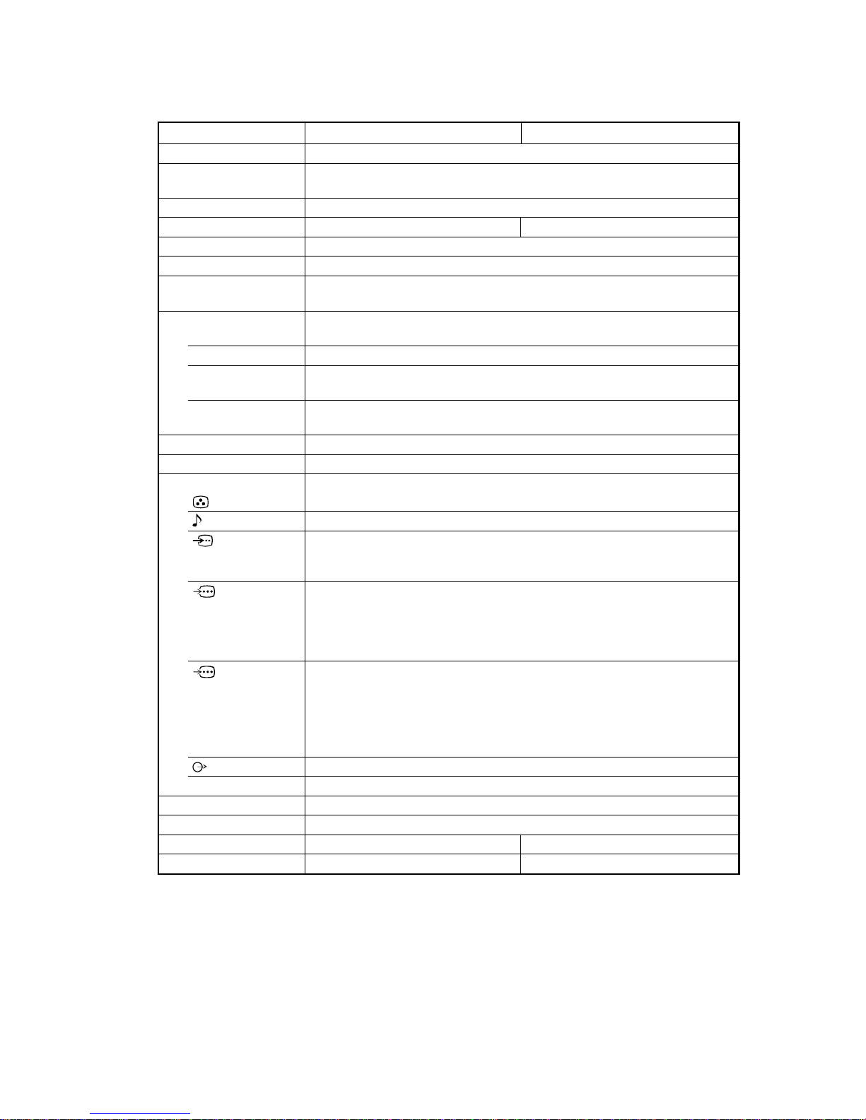
1-1. DIAGNOSTIC TEST INDICATORS
When an errors occurs, the STANDBY/TIMER lamp will flash a set number of times to indicate the possible cause of the problem. If
there is more than one error, the lamp will identify the first of the problem areas.
Result for all of the following diagnostic items are displayed on screen. No error has occurred if the screen displays a “0”.
002:000 or
002:001 ~ 255
003:000 or
003:001 ~ 255
004:000 or
004:001 ~ 255
005:000 or
005:001 ~ 255
006:000 or
006:001 ~ 255
007:000 or
007:001 ~ 255
101:000 or
101:001 ~ 255
No. of times
STANDBY/TIMER
lamp flashes
Detected Symptoms
Diagnostic
Item
Description
• Power does not
turn on
• +B overcurrent
(OCP)
• +B overvoltage
(OVP)
• Vertical deflection
failure
• White balance
failure
(no PICTURE)
• High Voltage
failure
• Audio Protection
• Micro reset
Self-diagnostic
display/
Diagnostic result
Probable Cause Location
Does not light
2 times
3 times
4 times
5 times
6 times
7 times
• Power cord is not plugged in.
• Fuse (F6701) is burned out.
(G board)
• H. OUT Q8024 is shorted.
• H. LIN Q8027 is shorted.
(D board)
• HV OUT Q8043 is shorted.
• PH6001 faulty.
• +19V is not supplied.
(G board)
• V. OUT IC8003 faulty.
(D board)
• G2 is improperly adjusted.
(Note 1)
• CRT problem.
• Video OUT IC9101 (CR
board), IC9201 (CG board),
IC9001 (CB board) are faulty.
• IC8306 (J board) and IC4300
(E board) are faulty.
• No connection E board to CR
board.
• IC6502 (G board) faulty.
• Power supply fails.
• IC1203,1204 (A board) faulty.
•Discharge CRT
(CR, CG, CB boards)
• Static discharge
• External noise
Note 1 : Refer to screen (G2) adjustment in section 4-2 of this manual.
– 6 –
KP-FS43M90/FS53M90
RM-998RM-998
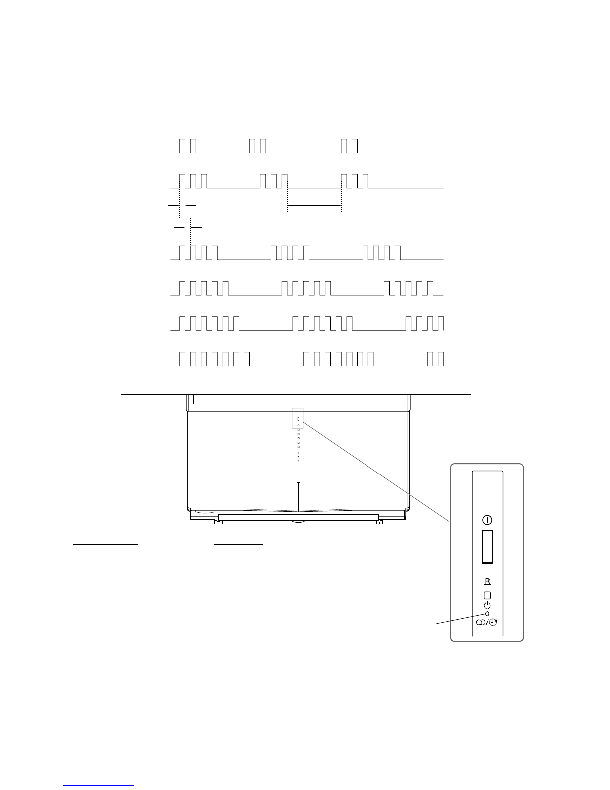
1-2. DISPLAY OF STANDBY/TIMER LIGHT FLASH COUNT
1-3. STOPPING THE STANDBY/TIMER FLASH
Turn off the power switch on the TV main unit or unplug the power cord from the outlet to stop the STANDBY/TIMER lamp from
flashing.
Diagnostic Item Flash Count *
+B overcurrent 2 times
+B overvoltage 3 times
V deflection stop 4 times
White balance failure 5 times
High voltage protector 6 times
Audio Protection 7 times
* One flash count is not used for self-diagnostic.
STANDBY/TIMER
lamp
Lamp ON
0.3 sec.
Lamp OFF
0.3 sec.
Lamp OFF
3 sec.
2 times
3 times
5 times
6 times
4 times
7 times

– 7 –
KP-FS43M90/FS53M90
RM-998RM-998
1-4. SELF-DIAGNOSTIC SCREEN DISPLAY
For errors with symptoms such as “power sometimes shuts off” or “screen sometimes goes out” that cannot be confirmed, it is possible
to bring up past occurrences of failure for confirmation on the screen:
[To Bring Up Screen Test]
In standby mode, press buttons on the remote commander sequentially in rapid succession as shown below:
5
(DIGIT 5) (VOLUME –) (POWER)ON SCREEN
DISPLAY
(
)
*
* : Note that this differs from entering the service mode (volume +)
Self-Diagnosis screen display
SELF DIAGNOSTIC
002:000
003:000
004:000
005:001
006:002
007:000
101:000
Numeral “0” means that no fault has been detected.
Numeral “1” means a fault has been detected.
Numeral “2” means two faults have been detected.
1-5. HANDLING OF SELF-DIAGNOSTIC SCREEN DISPLAY
Since the diagnostic results displayed on the screen are not automatically cleared, always check the self-diagnostic screen
during repairs. When you have completed the repairs, clear the result display to “0”.
Unless the result display is cleared to “0”, the self-diagnostic function will not be able to detect subsequent faults after completion of
the repairs.
[Clearing the result display]
To clear the result display to “0”, press button on the remote commander sequentially as shown below when the diagnostic screen is
being displayed.
[Quitting Self-diagnostic screen]
To quit the entire self-diagnostic screen, turn off the power switch on the remote commander or the main unit.
Press “8” button
(It will indicate “CLEAR” on the screen.)
Press “-” button
(The “CLEAR” display change to red color.)
,

– 8 –
KP-FS43M90/FS53M90
RM-998RM-998
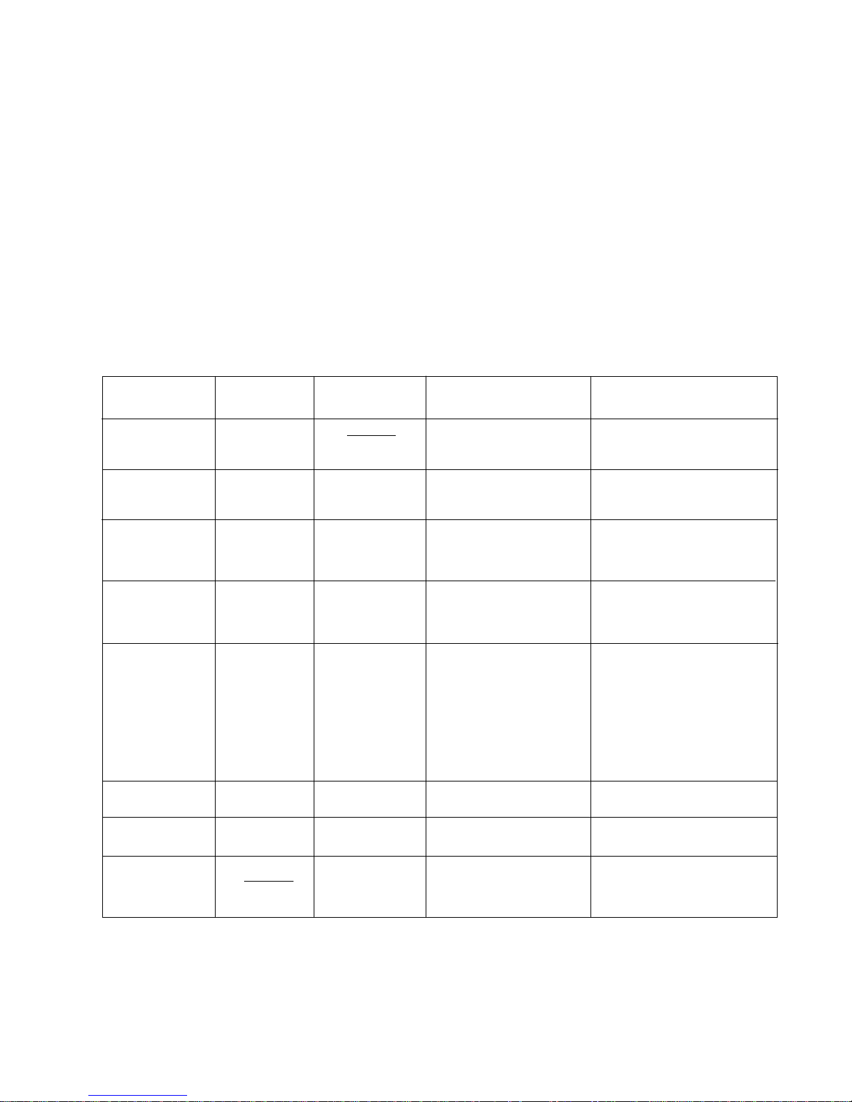
1-6. SELF-DIAGNOSTIC CIRCUIT
+B overcurrent (OCP) Occurs when an overcurrent on the +B (135 V) line is detected by Q6504.
If Q6504 go to ON, the voltage to pin 3 of IC001 go to UP. The unit will
automatically turn off.
+B overvoltage (OVP) Occurs when an overvoltage on the +B (135 V) line is detected by IC6502.
If IC6502 go to ON, then voltage to pin 6 of IC001 go to UP. The unit will
automatically turn off.
Vertical deflection failure Occurs when an absence of the vertical deflection pulse is detected by
Q8001 and D8001. Shut down the power supply.
White balance failure If the RGB levels do not balance or become low level within 5 seconds. This
error will be detected by IC4300.
TV will stay on, but there will be no picture.
High voltage protector of Horizontal Deflection Occurs when an overvoltage of horizontal pulse is detected by D8038 and
IC8006.
If the voltage of pin 1 of IC8006 goes to High, the voltage to pin 20 of
IC4300go to UP. The unit will automatically turn off.
Audio Protector If the Audio out lines become DC.This error will be detected by Q1211,
Q1209 and Q1210.
The unit will automatically turn off.
IC4300
Y/C JUNGLE
CXA2170Q CXP961048-003Q
24 IKINFrom CRT (IK)
From G board
From IC1203,1204
(A board)
To H1 board
57 XRAYFrom IC8005,8006
(D board)
56 V PROTFrom Q8001
(D board)
IC001
SYSTEM
IC003
MEMORY
5 OCP
OCP
8 OVP
OVP
LED1 22
SPPROT
100
H
V
SDA 52 13 SDA0 SDA1 SDA15 5
A boardE board
Q1209-1211
– 9 –
KP-FS43M90/FS53M90
RM-998 RM-998
SECTION 2
DISASSEMBLY
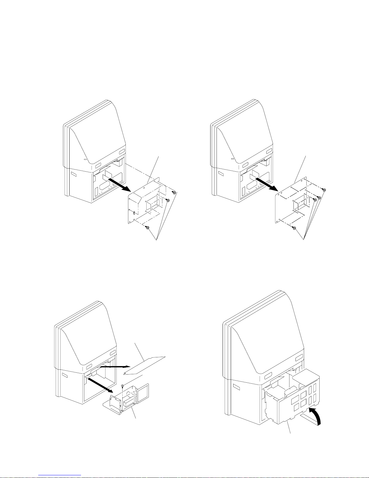
2-1. REAR COVER REMOVAL
(1) KP-FS43 (2) KP-FS53
2-2. MAIN BRACKET REMOVAL
1 Twelve screws
(BVTP 4X16)
2 Rear board
1 Ten screws
(Hexagon head)
2 Rear board
3 Main bracket section
1 Optical shield
2 Two screws
(tapping screw
hexagon head)
2-3. SERVICE POSITION
1 Main bracket section
– 10 –
KP-FS43M90/FS53M90
RM-998 RM-998
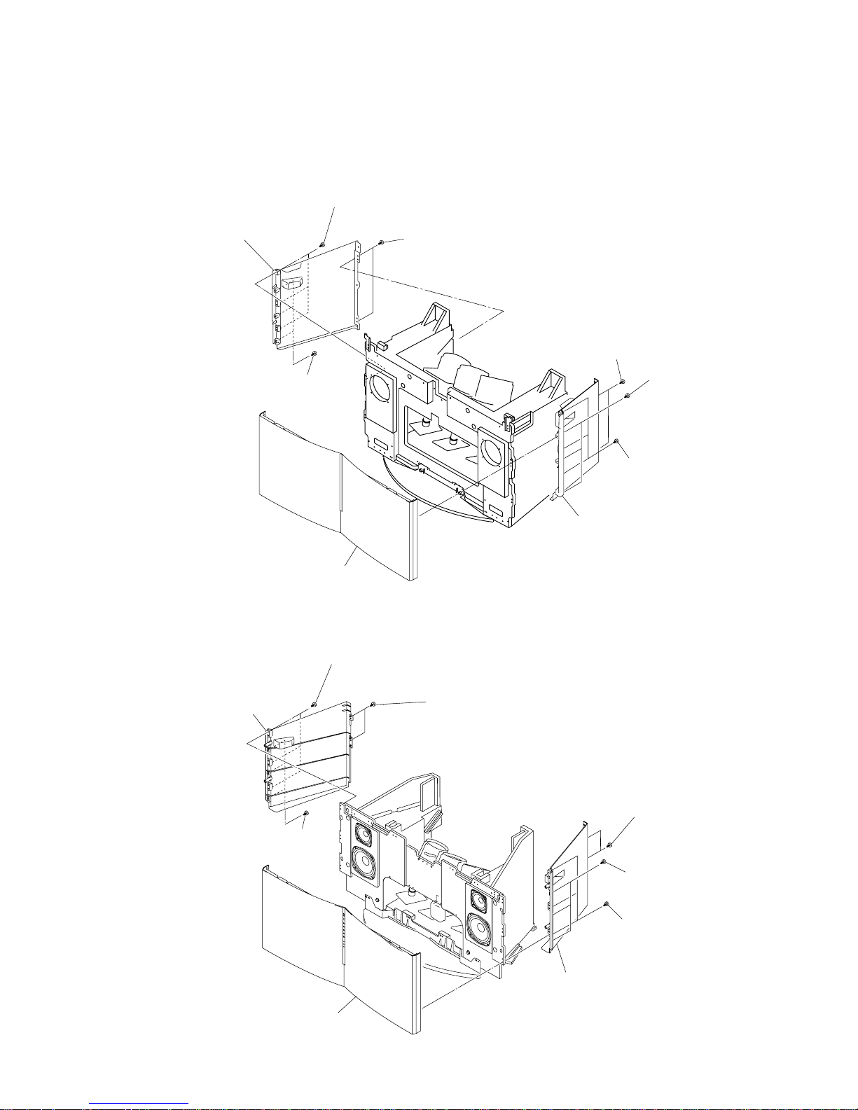
2-4. FRONT PANEL REMOVAL
(1) KP-FS43
(2) KP-FS53
1 Three screws
(BVTP 4x16)
1 Three screws
(BVTP 4x16)
3 Two screws
(BVTP 4x16)
3 Two screws
(tapping screw
hexagon head)
2 Three screws
(tapping screw
hexagon head)
2 Three screws
(tapping screw
hexagon head)
4 Side panel (43L) assy
5 Side panel (43R) assy
6 Front panel (43) assy
1 Three screws
(BVTP 4x16)
1 three screws
(BVTP 4x16)
3 Two screws
(tapping screw
hexagon head)
3 Two screws
(tapping screw
hexagon head)
2 Three screws
(tapping screw
hexagon head)
2 Three screws
(tapping screw
hexagon head)
4 Side panel (53L) assy
6 Front panel (53) assy
5 Side pane (53R) assy
– 11 –
KP-FS43M90/FS53M90
RM-998 RM-998
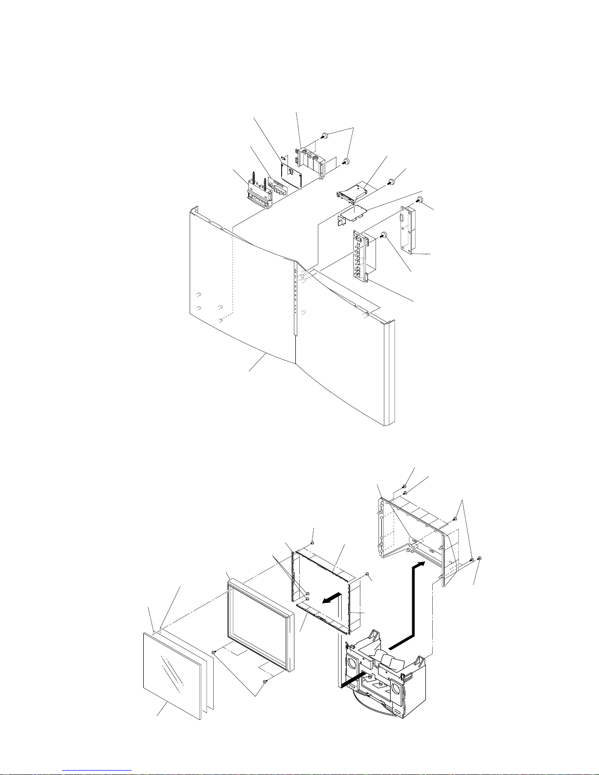
2-5. H1, H2 AND H3 BOARDS REMOVAL
2-6. BEZNET AND MIRROR COVER REMOVAL
1 Four screws
(BVTP 3x12)
6 Two screws
(BVTP 3x12)
4 Input terninal cover
2 Input terninal bracket
5 H3 board
3 Input terninal plate
9 Six screws
(BVTP 3x12)
0 H2 board
qa Four screws
(BVTP 3x12)
qs Control button
Front panel assy
7 H1 bracket
8 H1 board
2 Four screws
(BVTP 4X16)
2 Six screws
(BVTP 4X16)
1 Four screws
(Hexagon head)
2 Four screws
(BVTP 4X16)
0 Beznet assy
8 Screen
holder (V)
7 Screen holder (V)
6 Screen
holder (H)
9 Screen
holder (H)
qs Diffusion plate (F)
qd Diffusion plate (L)
qa Contrast screen
4 Four screws
(BVTP 4X12)
3 Mirror cover
5 Four screws (BVTP 3X12)
5 Four screws
(BVTP 3X12)
5 Ten screws (BVTP 3X12)
(1) KP-FS43

– 12 –
KP-FS43M90/FS53M90
RM-998 RM-998
2-7 MAIN BRACKET REMOVAL
(2) KP-FS53
2-6. BEZNET AND MIRROR COVER REMOVAL
2 Six screws
(BVTP 4X16)
1 Four screws
(Hexagon head)
2 Six screws
(BVTP 4X16)
2 Six screws
(BVTP 4X16 )
5 Four screws
(BVTP 3X12)
5 Four screws
(BVTP 3X12)
0 Beznet assy
8 Screen
holder (V)
7 Screen holder (V)
6 Screen
holder (H)
9 Screen
holder (H)
qs Diffusion plate (F)
qd Diffusion plate (L)
qa Contrast screen
4 Six screws
(Hexagon head)
3 Mirror cover
5 Six screws
(BVTP 3X12)
5 Ten (BVTP 3X12)
5 Four screws (BVTP 3X12)
2 Main bracket section
1 Two screws
(Tapping screw
hexagon head)
Pay particular attention to the wires
of each printed circuit boards when
puling out the mainbracket.
– 13 –
KP-FS43M90/FS53M90
RM-998 RM-998
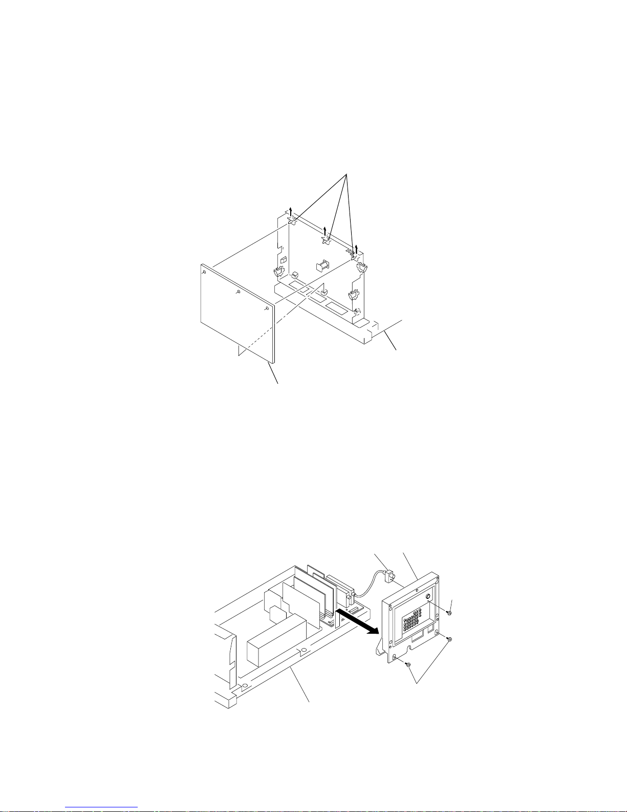
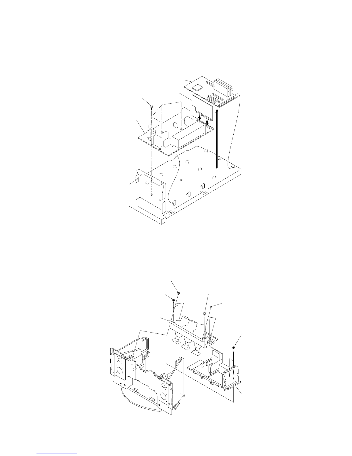
2-8. G BOARD REMOVAL
2-9. CONNECTOR COVER REMOVAL
3 Connector cover section
Main bracket section
1 Tow screws
(BVTP 4X16)
2 Screw
(PSW 2.6X6)
RF Connector
1 Three holder PWB
Main bracket section
2 G board
– 14 –
KP-FS43M90/FS53M90
RM-998 RM-998
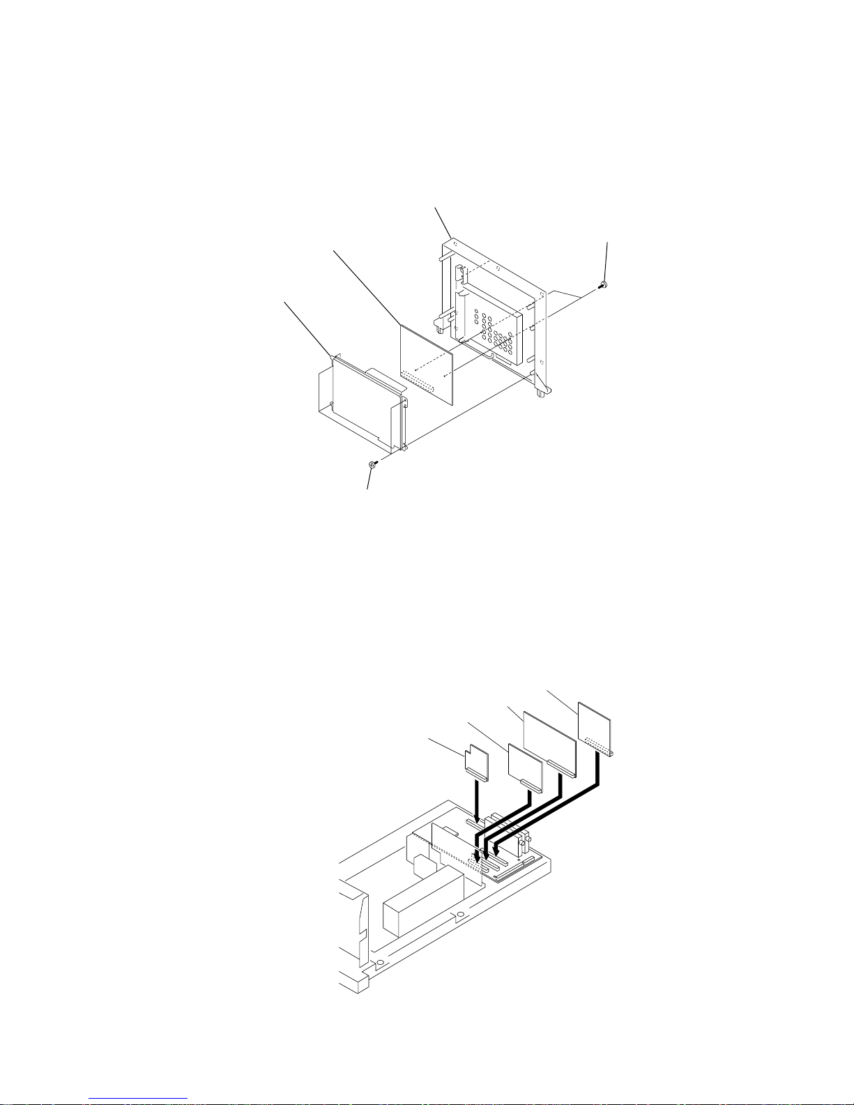
2-10. J BOARD REMOVAL
2-11. A1, E, B4 AND U2 B0ARDS REMOVAL
3 Tow screws
(BVTP 2.6X12)
1 Four screws
(BVTP 3X12)
5 Connector cover
4 J board
2 J board cover
1 A1 board
2 E board
3 B4 board
4 U2 board
– 15 –
KP-FS43M90/FS53M90
RM-998 RM-998
2-12. A, AD AND B BOARDS REMOVAL
2-13. PICTURE TUBE REMOVAL
1 A board
4 B board
3 Four screws
(BVTP 3X12)
2 AD board
5 Main bracket section
3 Picture tube block assy
2 Two screws
(Hexagon head)
4X20)
2 Two screws
(Hexagon head)
4X20)
4 Two screws
(Taping screw
hexagon head)
1 Two screws
(BVTP 4X16)
1 Two screws
(BVTP 4X16)

– 16 –
KP-FS43M90/FS53M90
RM-998 RM-998
2-14 HIGH-VOLTAGE CABLE
INSTALLATION AND REMOVAL
2-15. MECHASEAL
1 Four screws
(BVTP 4X16)
5 Four screws
(BVTP 4X16)
Removing the arrow-marked screw is strictly inhibited.
If removed, it may cause liquid spill.
2 CR board
3 Neck assy
4 Deflection yoke
6 Mechaseal assy (R)
7 Extension spring
(2) Installation
(1) Remover
1 Rubber cap
2 HV cable turn 90°
2 Rubber cap
1 HV cable
Hook
Gutter
– 17 –
KP-FS43M90, FS53M90
RM-998
RM-998
SECTION 3
SET-UP ADJUSTMENTS
3-1. SCREEN VOLTAGE ADJUSTMENT
(ROUGH ALIGNMENT)
1. Receive the Monoscope signal.
2. Set 50% BRIGHTNESS and minimum PICTURE.
3. Turn the red VR on the focus pack all the way to the left and
then gradually turn it to the right until the point where you
can see the retrace line.
4. Next gradually turn it to the left to the position where the
retrace line disappears.
Fig. 3-1
3-2. SCREEN (G2) ADJUSTMENT
1. Turn on the power of the set.
2. Select VIDEO1 mode without signals.
3. Supply DC 175 ±0.5 V from external power supply to
TP7103 (KR), TP7203 (KG) or TP7303 (KB) of CR board,
CG board and CB board.
3. Adjust red, green and blue screen voltage to until retrace
line disappears with screen VR on the focus pack.
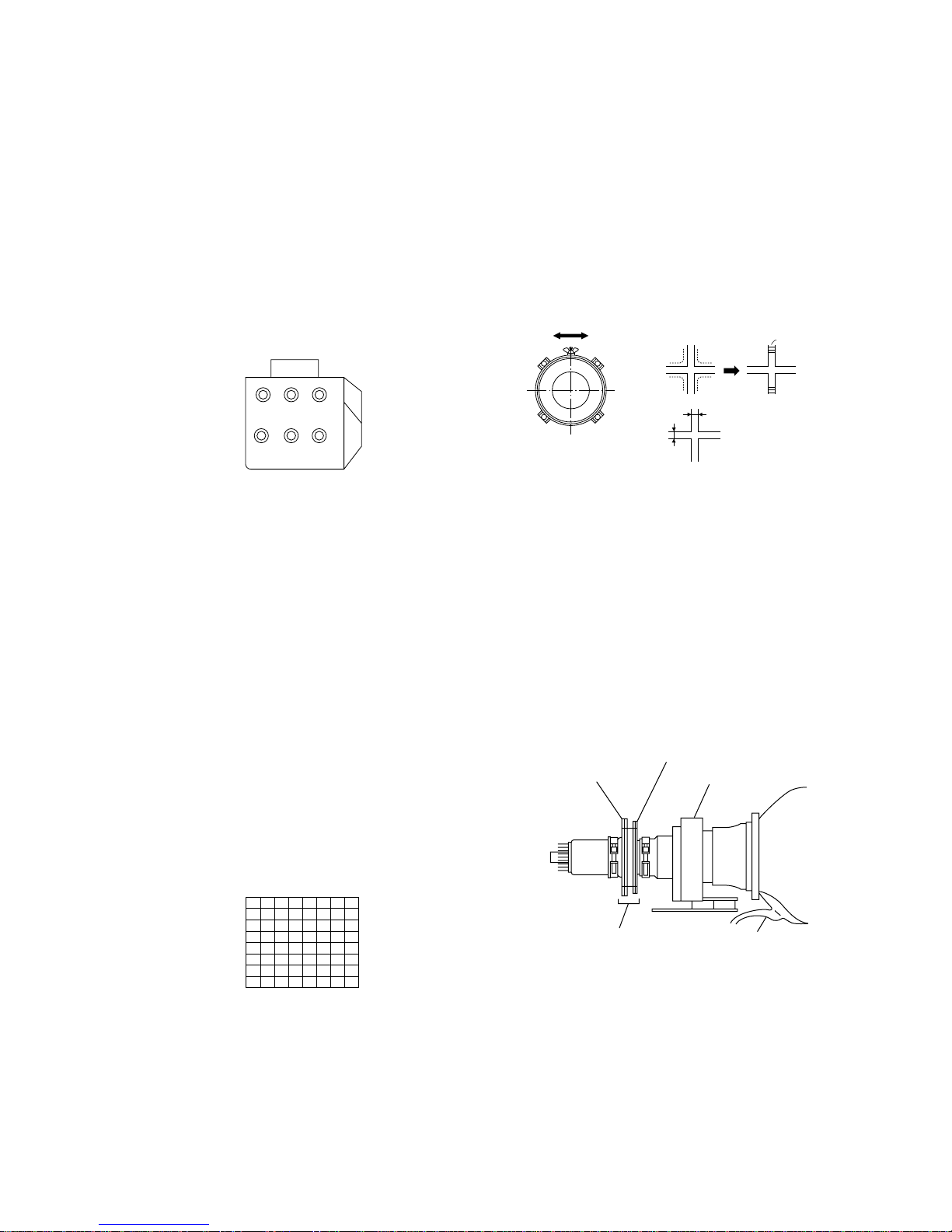
3-4. DEFLECTION YOKE TILT ADJUSTMENT
1. Receive the Monoscope signal.
2. Place the caps on the red and blue lens so that only the green
color.
3. Loosen the deflection yoke setscrew and align the tilt of the
Deflection yoke so that the bars at the center of the
monoscope pattern are horizontal.
4. After aligning the deflection yoke, fasten it securely to the
funnel-shaped portion (neck) of the CRT.
5. The tilt of the deflection yoke for red and blue is aligned the
same as was done for green.
Fig. 3-5
Neck Assy
Make sure deflection yoke is
touching CRT closely.
2-pole magnet
4-pole magnet
Deflection yoke
Anode cap
RG
SCREEN
B
RG
FOCUS
Focus Pack
B
Fig. 3-4
Lens
Fig. 3-3
Fig. 3-2
Test signal
Minimize both A and B.
A
B
Scanning line visible.
3-3. FOCUS ROUGH ADJUSTMENT
1. Loose the lens screw.
2. Set in the service mode. (Refer to SECTION 5.)
3. Place the caps on the red and blue lens so that only the green
color is shown.
4. Press “1” or “4” button on the commander and select
“PJE”, press “6” three times on the Commander to display
the test signal (crosshatch) on the screen.
5. Rotate the green lens and align to obtain the best lens focus
at the center area.
6. Rotate the green focus VR on the focus pack and align to
obtain the best electrical focus in the top right corner.
7. Perform the same alignment for red and blue lenses and electric focus.
8. Fix lens screw.
– 18 –
KP-FS43M90, FS53M90
RM-998
RM-998
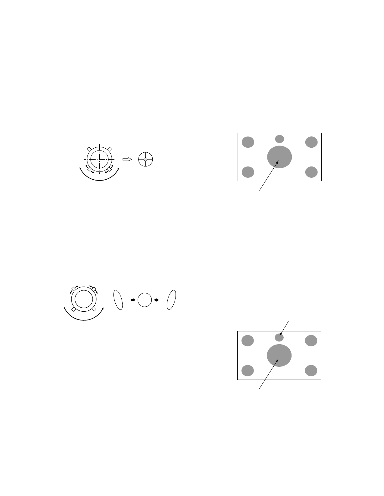
3-5. 2-POLE MAGNET ADJUSTMENT
1. Receive the Dot signal.
2. Place the caps on the red and blue lens so that only the green
color is shown.
3. Turn the green focus VR on the focus pack to the right and
set to over focus to enlarge the spot.
4. Now align the 2-Pole Magnet so that the enlarged spot is in
the center of the just focus spot.
(center of the dot doesn't move)
5. Align the green focus VR and set for just (precise) focus.
6. Perform the same alignment for red and blue.
Fig. 3-6
3-6. 4-POLE MAGNET ADJUSTMENT
1. Receive the Dot signal.
2. Place the caps on the red and blue lens so that only the green
color is shown.
3. Turn the green focus VR on the focus pack to the left and set
to under focus to enlarge the spot.
4. Now align the 4-Pole Magnet so that the enlarged spot becomes a perfect circle.
5. Perform the same alignment for red and blue.
Fig. 3-7
3-7. GREEN, RED AND BLUE FOCUS
ADJUSTMENT
3-7-1. Green, Red and Blue Lens Focus Adjustment
1. Receive the Monoscope signal.
2. Place the caps on the red and blue lens so that only the green
color is shown.
3. Rotate the green lens and adjust to obtain the best lens focus
at the center area.
4. Fix lens screw.
5. Repeat above process for red and blue.
3-7-2. Green, Red and Blue Electrical Focus
Adjustment
1. Receive the Monoscope signal.
2. Place the caps on the red and blue lens so that only the green
color is shown.
3. Rotate the green focus VR on the focus pack and adjust to
obtain the best electrical focus in the adjust point.
4. Repeat above process for red and blue.
5. Repeat adjustment items 3-3. FOCUS ROUGH ADJUSTMENT, 3-5. 2-POLE MAGNET ADJUSTMENT, 3-6. 4POLE MAGNET ADJUSTMENT and 3-7. GREEN, RED
AND BLUE FOCUS ADJUSTMENT, and adjust to obtain
the best focus.
Fig. 3-8
Adjust Point
Use the center dot
Use the center dot
OKNG NG
Adjust Point of Green and Red
Adjust Point of Blue
Fig. 3-9
 Loading...